master's thesis: implementation of extended motion...
TRANSCRIPT

Implementation of extended motioncapture support in Android smartphonesMaster of Science Thesis in the Master Degree ProgrammeSoftware Engineering & Technology
WILLIAM LOFALEXANDER WIDAR
Department of Computer Science & EngineeringChalmers University of TechnologyGothenburg, Sweden 2012Master’s Thesis 2012

The Author grants to Chalmers University of Technology and University of Gothen-burg the non-exclusive right to publish the Work electronically and in a non-commercialpurpose make it accessible on the Internet.The Author warrants that he/she is the author to the Work, and warrants that the Workdoes not contain text, pictures or other material that violates copyright law.
The Author shall, when transferring the rights of the Work to a third party (for examplea publisher or a company), acknowledge the third party about this agreement. If theAuthor has signed a copyright agreement with a third party regarding the Work, theAuthor warrants hereby that he/she has obtained any necessary permission from thisthird party to let Chalmers University of Technology and University of Gothenburg storethe Work electronically and make it accessible on the Internet.
Implementation of extended motion capture support in Android smart-phones
WILLIAM LOFALEXANDER WIDAR
c© WILLIAM LOF, JUNI 2012.c© ALEXANDER WIDAR, JUNI 2012.
Examiner: SVEN-ARNE ANDREASSON
CHALMERS UNIVERSITY OF TECHNOLOGYUniversity of GothenburgDepartment of Computer Science and EngineeringSE-412 96 GoteborgSwedenTelephone + 46 (0)31-772 1000
Cover:The Android robot juggling motion capture markers
Department of Computer Science and EngineeringGoteborg, Sweden May 2012

Abstract
This thesis is a study in smartphone applications on the Android platform that commu-nicates with a motion capture system in real-time. The thesis covers the work in portinga C library to Android Java with NDK in order to utilize already written motion capturesystem communication code. Three different Android applications were developed basedon this port; a remote control application, a viewfinder application and a virtual cameraapplication. For illustration, the OpenGL library is used and hence it is also covered.Comparisons between the iOS application ditos are made and interviews were conductedin order to determine how and when the applications are useful. Throughout the projectan agile like inhouse development process was utilized at the Swedish motion capturecompany Qualisys. At the end of this paper, some issues and suggestions on future workare brought to the surface.
Keywords: smartphone, android, motion capture, realtime communication
Sammanfattning
Denna rapport ar resultatet av en studie om smartphoneapplikationer som kommunicerarmed ett motion capture-system i realtid. Rapporten tacker arbetet med att porta ettC-bibliotek till Android Java med hjalp av NDK for att ta vara pa redan skriven kom-munikationskod. Tre olika Androidapplikationer blev utveckladade baserat pa dennaport, en fjarrkontrollsapplikation, en sokarapplikation samt en virtuell kameraapplika-tion. For illustration anvandes OpenGL-biblioteket och darmed tacks detta aven avrapporten. Jamforelser med iOS applikationsditos gors samt intervjuer genomfors foratt ta reda pa nar och hur applikationerna ar anvandbara. Genom hela projektet an-vandes en agil-liknande inhouse utveckliningsprocess hos det svenska motion captureforetaget Qualisys. I slutet av rapporten lyfts nagra problem till ytan samt forslag paframtida utveckling.


Contents
1 Introduction 11.1 Previous work . . . . . . . . . . . . . . . . . . . . . . . . . . . . . . . . . . 1
1.1.1 Viewfinder . . . . . . . . . . . . . . . . . . . . . . . . . . . . . . . 11.1.2 QTM Remote . . . . . . . . . . . . . . . . . . . . . . . . . . . . . . 2
1.2 Purpose . . . . . . . . . . . . . . . . . . . . . . . . . . . . . . . . . . . . . 21.3 Goals . . . . . . . . . . . . . . . . . . . . . . . . . . . . . . . . . . . . . . 31.4 Scope . . . . . . . . . . . . . . . . . . . . . . . . . . . . . . . . . . . . . . 3
2 Background 42.1 Motion Capture . . . . . . . . . . . . . . . . . . . . . . . . . . . . . . . . . 4
2.1.1 Purpose of motion capture . . . . . . . . . . . . . . . . . . . . . . 42.1.2 Motion capture basics . . . . . . . . . . . . . . . . . . . . . . . . . 4
2.2 Qualisys . . . . . . . . . . . . . . . . . . . . . . . . . . . . . . . . . . . . . 52.3 Android . . . . . . . . . . . . . . . . . . . . . . . . . . . . . . . . . . . . . 7
2.3.1 History . . . . . . . . . . . . . . . . . . . . . . . . . . . . . . . . . 82.3.2 Android development . . . . . . . . . . . . . . . . . . . . . . . . . 8
2.4 OpenGL . . . . . . . . . . . . . . . . . . . . . . . . . . . . . . . . . . . . . 92.4.1 Why OpenGL? . . . . . . . . . . . . . . . . . . . . . . . . . . . . . 92.4.2 OpenGL on Android . . . . . . . . . . . . . . . . . . . . . . . . . . 10
3 Method & Development Process 113.1 Literature Study . . . . . . . . . . . . . . . . . . . . . . . . . . . . . . . . 113.2 Development . . . . . . . . . . . . . . . . . . . . . . . . . . . . . . . . . . 11
3.2.1 Basic agile approach . . . . . . . . . . . . . . . . . . . . . . . . . . 123.2.2 Android SDK . . . . . . . . . . . . . . . . . . . . . . . . . . . . . . 123.2.3 Eclipse . . . . . . . . . . . . . . . . . . . . . . . . . . . . . . . . . . 13
3.3 Interviews . . . . . . . . . . . . . . . . . . . . . . . . . . . . . . . . . . . . 13
i

CONTENTS
4 Implementation & Result 154.1 Deliverables . . . . . . . . . . . . . . . . . . . . . . . . . . . . . . . . . . . 15
4.1.1 Internals . . . . . . . . . . . . . . . . . . . . . . . . . . . . . . . . . 154.1.2 QTM Remote control . . . . . . . . . . . . . . . . . . . . . . . . . 174.1.3 QTM Viewfinder . . . . . . . . . . . . . . . . . . . . . . . . . . . . 194.1.4 QVC . . . . . . . . . . . . . . . . . . . . . . . . . . . . . . . . . . . 22
4.2 Interviews . . . . . . . . . . . . . . . . . . . . . . . . . . . . . . . . . . . . 26
5 Discussion 275.1 Android adaptations of iOS applications . . . . . . . . . . . . . . . . . . . 275.2 Usefulness of the applications . . . . . . . . . . . . . . . . . . . . . . . . . 28
5.2.1 QTM Remote Control . . . . . . . . . . . . . . . . . . . . . . . . . 285.2.2 QTM Viewfinder . . . . . . . . . . . . . . . . . . . . . . . . . . . . 285.2.3 QVC . . . . . . . . . . . . . . . . . . . . . . . . . . . . . . . . . . . 28
5.3 Java and NDK . . . . . . . . . . . . . . . . . . . . . . . . . . . . . . . . . 295.4 Known issues and limitations . . . . . . . . . . . . . . . . . . . . . . . . . 295.5 Future work . . . . . . . . . . . . . . . . . . . . . . . . . . . . . . . . . . . 30
6 Conclusion 32
References 34
A Appendix: Interview Questions 35
ii

Abbreviations
6DOF 6 Degrees Of Freedom, defines a rigid body
ADB Android Debug Bridge
API Application Programming Interface
IDE Integrated Development Environment
JNI Java Native Interface
MIT Massachusetts Institute of Technology
NDK Native Development Kit
QTM Qualisys Track Manager
RT Real-Time
UDP User Datagram Protoco
TCP Transmission Control Protocol
IP Internet Protocol
VM Virtual Machine
WLAN Wireless Local Area Network
XML Extensible Markup Language


1 Introduction
This is a master thesis written in the Software Engineering and Technologymaster program at Chalmers University of Technology. It is performed in con-junction with the company Qualisys AB, which provides products and servicesrelated to optical motion capture. This thesis focuses on the implementation
and evaluation of a set of tools, implemented for the Android platform, for the company’ssystem. Some of the tools have been previously developed for the iOS platform and aremore or less directly translated into the Android platform, whereas one of the tools doesnot already exist and is designed from scratch.
1.1 Previous work
In 2010 a master thesis named “Implementation of motion capture support in smart-phones” was carried out at Qualisys. The goal of that thesis was to implement an APIfor the company’s Real-Time Protocol and use that to implement iOS applications fora viewfinder for seeing what the cameras of a motion capture system see and a virtualgoniometer. Another goal was to investigate cross-platform development of applicationsfor iOS and Android (Martinsson & Trost 2010).
1.1.1 Viewfinder
As the name suggest, the viewfinder application is meant to show what the cameras inthe company’s motion capture environment see. By streaming the information from aserver, the application shows in real-time what is in the cameras’ field of view. Thisis helpful when the cameras are to be mounted in a place that is hard to reach andthe camera picture can be viewed in a handheld device. There are three modes ofthe motion capture system that the Viewfinder can show. The user can also use theviewfinder application to change some system settings (Martinsson & Trost 2010).
1

1.2. PURPOSE CHAPTER 1. INTRODUCTION
Figure 1.1 The iOS Viewfinder
1.1.2 QTM Remote
QTM remote is an application that was developed at Qualisys by the same people whodid the previously mentioned master thesis. The remote application was, however, nota part of the thesis and is therefore a separate related work. The application makes itpossible for users of the Qualisys motion capture system, to trigger motion recordingremotely by their handheld device and marking events on the recorded time-line. It alsolets the user save the recordings to files on the computer and is also compatible with theso called batch capture, where saving happens automatically (Qualisys 2012).
Figure 1.2 The iOS QTM Remote
1.2 Purpose
The purpose of this thesis is:
• To extend functionality already found in the iOS platform to the Android platform
2

1.3. GOALS CHAPTER 1. INTRODUCTION
• To explore 3D functionality of the Qualisys system by implementing a virtualcamera
• To work in a realistic way with Qualisys as a customer
• To fulfill the goals specified in 1.3
The purpose also includes answering the following research questions:
• How will the portability of a handheld android device help in configuring, maneu-vering and maintaining a Qualisys motion capture system?
• Will the extension to 3D handheld functionality provide any advantages to the 2Dfunctionality?
• Are there limitations of a handheld android device when implemented in the Qual-isys motion capture environment?
1.3 Goals
The goals of this thesis are divided in two different phases. The first phase consistsof using the existing C library to develop the two previously iOS applications for theAndroid platform. The second phase will be an extension with a 3D implementationin the form of a so called virtual camera. Assessing the usefulness of the differentapplications is also a part of the goals.
1.4 Scope
The implementation will be the the most time-consuming part of the thesis and willinclude the development of the two existing iOS applications in Android as well as the3D implementation. An evaluation will be conducted after the implementation and willbe limited to the opinions of the employees at Qualisys since there will not be enoughtime to take the opinions of end users.
3

2 Background
Chapter two of this thesis covers background information on the different tech-nologies and concepts that was used during the project. This is informationthat is important to know beforehand in order to understand the results ofthe thesis. The basics of motion capture is covered as well as the company
Qualisys, where the thesis was housed, the Android platform and the graphics libraryOpenGL.
2.1 Motion Capture
Motion capture is the procedure of recording live motion into a digital 3D represen-tation. This is usually done by tracking a number of landmarks on a recorded objectand combining them into a viable digital presentation. The object of interest can beanything with a motion that is desirable to record. The landmarks should be the pointsthat best represent the object’s movement and links between rigid sections. When cap-turing, e.g. human motion, some obvious landmarks are the joints between body parts(Menache 2010).
2.1.1 Purpose of motion capture
Motion capture has a number of applications, analytic like in biomechanics where track-ing of motion is used e.g. as an aid in gait analysis to help in rehabilitation of injuredpeople (Cloete & Scheffer 2008) and industrial purposes where it can be used for e.g.measuring and evaluating the efficiency of industrial robots (Qualisys 2011b). There arealso real-time applications, such as tracking a head-mounted display in order to showthe proper information on the screen or as a tool in computer-aided surgery, where itcan allow for more precise placement of hip prosthetics or tracking of probes in breastbiopsies (Welch 2002).
2.1.2 Motion capture basics
The tracking of the previously mentioned landmarks are done by placing markers orsensors on them and collecting the information given by them. Whether it is sensoror markers that are used depends on what type of system it is and motion capture isusually categorized into the following types: outside-in, inside-out and inside-in.
4

2.2. QUALISYS CHAPTER 2. BACKGROUND
• In outside-in systems the sensors are external and placed around the measuredspace, collecting data from markers placed on the measured objects. One exampleof this is camera-based systems in which cameras receive information from reflectiveor light-emitting markers placed on an object.
• In contrast, inside-out systems have sensors placed on the object of interest andreceive data from external sources. An example of this is electromagnetic systems,where a electromagnetic field is generated over the area and sensors placed on theobject.
• Inside-in systems are systems in which both sources and sensors are placed onthe object. For example, in a system based on inertial sensing used in humanmotion capture, accelerometers and/or gyroscopes are placed on the subject assensors and the sources of data are the joints and movement of the subject itself(Menache 2010).
2.1.2.1 Optical System
Optical motion capture systems are usually outside-in system in which you mount cam-eras around the measured space and put markers on the subject. The markers can eitherreflect light hitting them, called passive markers, or actually emit light on their own,called active markers (Welch 2002). At Qualisys they mostly use passive markers. Thecameras measuring are emitting infrared light from an array of diodes around the lens.The emitted light is then reflected by the markers and thus recognized by the system.
2.2 Qualisys
Qualisys is a company focusing on motion capture services and products, which over theyears has become globally leading providers of these. Based in the port city Gothen-burg, Sweden, the company has been developing their products since 1989. Fields ofapplications where Qualisys is active are: sport science, psychology, gait analysis & re-habilitation, neurology, mri scanner rooms, marine applications, animation and virtualreality (Qualisys 2011a).
Figure 2.1 The Qualisys logotype
The main software of the Qualisys motion capture system is called QTM - QualisysTrack Manager. Through this software, the user is able to control, calibrate and edit
5

2.2. QUALISYS CHAPTER 2. BACKGROUND
measurements. The software gives the user visual feedback about what is going on in thesystem in real-time. (Qualisys, 2011b) The different kinds of data that can be accessedfrom the cameras with QTM are:
• Marker mode - shows white dots representing markers.
• Intensity mode - see what is interpreted as markers.
• Video mode - grayscale video.
Every mode is a 2D-representation of what each camera sees. With this 2D informa-tion, QTM calculates a 3D representation of the volume. From this, it can also recognizepreviously defined rigid bodys which are called 6DOF. 6DOF bodies are a set of markersthat are attached to the same object and therefore retain their relative position as thebody moves. Besides data regarding markers, QTM can also record analog input fromequipment such as pressure plates1, sound or video recordings that can be matched withthe measurements. (Qualisys 2008)
Figure 2.2 Qualisys Track Manager
The RT Protocol (Real-Time Protocol) is a part of QTM. The protocol allows for networkbased communication with the Qualisys motion capture system over TCP/IP or UDP/IP.Through various commands, different system settings can be set and streaming of datain real-time can be achieved. Examples of different kinds of information that can bestreamed in real-time are 2d-markers, 3D-markers, video, marker intensity and 6DOF(rigid bodies). (Nilsson 2012)
1A pressure plate records pressure, or weight.
6

2.3. ANDROID CHAPTER 2. BACKGROUND
There exists an API intended for communication with QTM through the RT Protocoland it is called QTMAPI - Qualiys Track Manager Application Programming Interface.The API was developed, in the programming lanuage C, 2010 as a part of the iPhoneapplication development (see 1.1). QTMAPI offers almost full functionality of version1.9 of the RT Protocol. (Martinsson & Trost 2010)
2.3 Android
Android is a platform primarily developed for use on mobile devices. It is maintainedby the Open Handset Alliance which consists of a number of hardware and electronicsmanufacturers, software companies and network operators, and is led by Google. Theplatform is open source under the GNU General Public License and Apache 2.0 license,which makes it available to anyone to download and make changes, but official customreleases must be approved by Google. The major releases of the platform are eachdesignated a name of a dessert and the latest version as of this moment is Ice CreamSandwich with the version number 4.0 (Helal, Bose & Li 2012).
Android has experienced a rapid growth during the last few years and gains more andmore of the market share (see figure below). January through October 2011, Androidaccounted for 53% of all smartphones sold in the U.S. (NDP 2011). Since Androidgets more and more widespread, developed applications for this platform reaches morecustomers. For a company that only provides their applications for the iOS platform,this is a strong motivation to develop them for Android as well.
Figure 2.3 Smartphone sales in the U.S. (BGR 2011)
7

2.3. ANDROID CHAPTER 2. BACKGROUND
2.3.1 History
In 1999 the company Android, Inc. was founded to develop a new mobile platform. In2005 it was acquired by Google. The development of the platform progressed and anumber of other companies joined in a partnership, which in 2007 resulted in the OpenHandset Alliance. The first phone running Android 1.0 came in 2008 and the platformhad a very rapid growth rate much due to the quick updates and the fact that a numberof partners launched their own devices, running Android, which gained popularity amongusers. The platform is also attractive to developers as most of it is open source and thismakes it modifiable for use in a large variety of devices ranging from mobile phones totablets and even entertainment systems in cars. The estimations of today say that thereare over 250 million devices in the world that run Android and it is still growing (Helalet al. 2012).
2.3.2 Android development
Android applications are developed using the programming language Java and the ap-plication framework of the Android Software Development Kit. However, Android doesnot completely support standard Java. This is mostly due to key differences in somestandard libraries, among them user interface libraries in particular. The applicationsare executed in Dalvik Virtual Machine which is optimized for use on mobile devicesand a minimal memory footprint. All applications are run in a separate VM and kernelprocess, which Dalvik has been written to handle well (Android 2012).
2.3.2.1 Native Development Kit
The Android Native Development Kit is a toolset created to allow developers to usenative code in Android applications. When an application is written in Java, the code iscompiled into bytecode which needs to be interpreted by a VM whereas native code runsdirectly on the processor without any need of interpretation. When native code is used,the compilation takes place in the development environment and not on the Androidplatform, as opposed to Java, where the Dalvik Just-In-Time compiler translates thebytecode into native code on the device. Even though it might sound as a performanceboost to use only native code, in reality switching from Java to native takes time. Also,the Dalvik compiler produces effective native code, which in many cases makes it atleast as good as developer written code. In short, the NDK provides a way to developapplications partly or fully in C/C++, which can be very useful if there is e.g. a pre-existing library in C/C++ that a developer needs to use in an Android application(Guihot 2012).
2.3.2.2 The need for a versatile application
Devices that run Android come in a lot of different shapes and sizes and with or withoutcertain hardware. The openness of the platform has made it possible for a lot of differentmanufacturers to produce their own Android device. Android is not only used in phones
8

2.4. OPENGL CHAPTER 2. BACKGROUND
but also in tablets and even in certain TVs etc. Although this diversity is good for theplatform as well as device manufacturers, it might pose a slight challenge for developers.An application should be usable by as many devices as possible in order to reach agreater audience, but that also means that the developer must design it that way. Inorder to support devices with different screen sizes and resolutions, a developer canprovide different layouts and graphical elements with different resolutions. Android willdecide at runtime which of the resources that are appropriate.
In addition to devices with different screen properties, some devices might not havethe required hardware for certain applications and then a developer should make surethat such devices should not be able to install the application. To provide an example;what good is a barcode scanner application that utilizes the camera on a device with nocamera? The software designer should declare what features and hardware his or herapplication uses and in that way, the application will not be shown in the Google PlayStore2 to people who have devices with insufficient resources (Android 2012).
2.4 OpenGL
OpenGL (originally Open Graphics Library) is a library for developing 2D and 3D graph-ics. It was introduced in 1992 and has since then gained a lot of popularity and beenadapted to many operating systems. The standard is used in many different contexts,where advanced graphics is used, like in the gaming industry. Since 2006 OpenGLhas been managed by a consortium named Khronos Group which was founded in 2000and consists of companies like NVIDIA, ATI Technologies and the original creator ofOpenGL, Silicon Graphics, Inc. (Hashimi, Komatineni & MacLean 2010).
2.4.1 Why OpenGL?
Android offers a set of graphic libraries that can be used to render your graphics on thescreen. They have advantages and disadvantages and are used in different situations:Graphics through canvases and drawables is the standard way of Android graphics. Thisis how all standard user interface components are drawn and is also mostly used whencreating a custom component. This can also be used to draw directly onto a canvaswhich is mostly the case in 2D games where all drawing and updating of graphics isdone “by hand”.
Canvas and drawables with hardware acceleration provides the same 2D graphicslibraries as above but as of Android 3.0 hardware acceleration is available for mostcomponents, raising its performance.
OpenGL can be used to render more advanced graphics using features such as 3D. InAndroid it is accessed either through the regular framework API or the NDK, developingnative OpenGL code. Using the framework causes some drop in performance comparedto native, but is still perfectly usable, although when developing applications with heavygraphics demand, the use of the native framework should be considered. The biggest
2Online portal for buying and downloading Android applications.
9

2.4. OPENGL CHAPTER 2. BACKGROUND
advantage is that OpenGL is well documented and accepted as a standard in manydifferent contexts (Android 2012).
Renderscript is a form of native code for android that provides high performance3D graphics rendering similar to NDK OpenGL, but also offers a powerful computationAPI. Renderscript code is compiled and cached at runtime on the device, which makesit possible to use on a variety of Android devices and thus highly portable. However,the main disadvantage of Renderscript is that it introduces completely new APIs whichare not as documented as OpenGL (Android 2012).
One of the end goals of this project is to render graphics in a 3D environment,consistent with reality. For this purpose, the use of canvases and drawables is not wellsuited. For 3D rendering both OpenGL and Renderscript qualify, but since OpenGL ismore of a standard and is more documented than Renderscript, it is the library of choicein this project.
2.4.2 OpenGL on Android
OpenGL ES is a version of OpenGL meant for embedded systems and is suitable formobile devices. It is a lightweight version of regular OpenGL with a lot of conveniencefunctions taken away. Android supports OpenGL ES 1.0 since Android version 1.0 andOpenGL ES 2.0 since Android version 2.2. OpenGL ES is closely related to standardOpenGL and also has a large supply of documentation (Android 2012).
10

3 Method & Development Process
Here the work methods that are used in the thesis in order to reach the goals aredescribed. How the information was gathered in the initial phases is describedand how the actual work was carried out. This covers literature study andhow the applications was developed as well as with which tools. Finally, it
also depicts how the information basis for the evaluation was collected.
3.1 Literature Study
In order to gather knowledge about the motion capture domain and to give a betterunderstanding of the reasons and background of the thesis a literature study was per-formed. It is a summary of a variety of published documents in the area relating to thissubject (Taylor 2008).
The gathering of information about the theory of motion capture and especiallyoptical motion capture, was conducted by studying scientific papers and articles. Like innormal literature study, the material studied was organized around the research questionsof the thesis and in line with the thesis’ purpose (Writing 2010). As for the specificknowledge of the Qualisys system, in-house documents and specifications were studiedand the staff were asked questions.
Documentation and guides on how to use the Android NDK were studied quiteextensively to gain knowledge on how to use the existing C library for the real-timeprotocol. First party material, such as Android development guides, as well as thirdparty documents, as e.g. developer blogs, to widen the comprehension for the subject.
As an aid in the graphical part of the development, many sources for documentationon OpenGL was used. Official, unofficial, first party and third party as well as askingexperienced co-workers, all possible sources of information were used to get a betterpicture of the problem at hand.
3.2 Development
The actual development of the Android application is described in this section. Bothdevelopment process and tools are discussed.
11

3.2. DEVELOPMENT CHAPTER 3. METHOD & DEVELOPMENT PROCESS
3.2.1 Basic agile approach
When developing the applications a simple agile approach was used with some of the basicvalues of agile processes. Two of the points in the agile manifesto were highlighted morethan the other two during the project, namely “customer collaboration over contractnegotiation” and “responding to change over following a plan”. These two points mixedwith the idea of a high degree of communication both in the team and with the customerwas a suitable combination since the project was carried out in house and the customer,which in this case was the supervisor at the company, was available at almost all times.This emphasis on communication and flexibility was realized through regular meetingswith the supervisor, where the team reported the progress and the supervisor had hissay in the development of the project (Cohen, Lindvall & Costa 2004).
A basic version of the agile notion of iterations was used throughout the thesis. Smallpackages of functionality ordered in logical steps were developed one at a time and slowlyled to the finished products.This also adds to the ability to respond to changes and senseof flexibility in the project (Cohen et al. 2004).
3.2.1.1 Requirements elicitation
The requirements for the applications that already were present for the iOS platformwere taken from the actual applications. Their design and behaviour were examinedand the functionality was divided in logical parts and continuously implemented for theAndroid applications.
However, the third application, the virtual camera, did not already exist and therequirements had to be taken from elsewhere. Meetings were held with the supervisorat the company and the basic requirements were established and informally stored.
3.2.1.2 Pair Programming
During the thesis, pair programming was heavily used. Nearly all programming werecarried out as a pair and that helped in increasing the understanding of the project asa whole. The team members were taking turns in being the programming part. It isargued that since pair programming is a kind of instant peer review, fewer defects areproduced. It is also argued that pair programming decreases the need of competence andexperience of the individuals since it provides a sort of mentoring between the partiesinvolved (Cohen et al. 2004).
3.2.2 Android SDK
The Android SDK is a compilation of the all the classes and components that are usedby the Android framework. The SDK is a necessity for developers to write Android ap-plications, since all the necessary tools are included. Not only components for the actualdeveloping is included, but also other vital tools like the Android Debug Bridge whichessentially handles communications between the development machine and Android de-vice (Android 2012). Another handy tool that is included in the SDK is the Android
12

3.3. INTERVIEWS CHAPTER 3. METHOD & DEVELOPMENT PROCESS
Emulator. The Emulator is a virtual Android device that runs on the developers com-puter. It is put to good use when testing an application during or after development,when testing without using a physical device is desired. However, the Emulator hassome limitations that makes it less than ideal for testing in several cases, e.g it does notsupport hardware sensors (Android 2012).
3.2.3 Eclipse
Eclipse is an open-source IDE, that was created in 2001 by IBM. Nowadays it is main-tained by the Eclipse Foundation, a non-profit organisation founded in 2004. The IDEis focused on providing tools for developing, debugging, testing and providing all othersorts of tools for maintaining software throughout its life-cycle (Eclipse 2012).
Eclipse was used as the development environment through the whole thesis, due toits versatility and the fact that there exists a plugin that facilitates Android development(see 3.2.3.1).
3.2.3.1 ADT
Android Development Tools is a plugin for Eclipse that presents the user with a setof tools for easier Android development. These tools enables the developer, amongother things, to edit XML-files both as text and as graphical form and to edit theuser interface graphically by dragging components to the right place. They also allowdevelopers to create Android projects in an easy way and run them directly from Eclipseon an Emulator or Android device. Tools for debugging and testing in Eclipse are alsoprovided (Android 2012).
3.2.3.2 C/C++ Development tools
During the development in the thesis, a portion of the work was done in C in order towrap the QTMAPI functions with the help of Android NDK to be used in Java. Forthe purpose of developing in C, the Eclpise plugin C/C++ Development Tools was used.C/C++ Development Tools offers functionality of a C/C++ IDE in the developmentplatform. It offers features such as syntax highlighting, code refactoring and generation,autocompletion and other useful tools when writing C code (Eclipse 2010).
3.3 Interviews
After the implementation was done, some interviews were conducted in order to assessthe usefulness of the applications and thereby helping to fulfill the purpose of the thesis.The questions in the interviews were designed to obtain an objective view on how theapplications contribute to the system in terms of installation and maintenance. Thequestions were also meant to provide a view on how the 2D and 3D implementationsdiffer. The interviewees were some people at Qualisys and, if possible, a customer oftheirs. The question about the QTM Remote and the Viewfinder can be answered based
13

3.3. INTERVIEWS CHAPTER 3. METHOD & DEVELOPMENT PROCESS
upon previous experience with the iOS versions, since they are almost identical. Thederived questions are found in Appendix A.
14

4 Implementation & Result
This chapter presents the results derived from the work in the thesis. First theresults from the actual development are presented which covers each applica-tion of the three. How the applications work is explained as well as how theyare engineered. The general internals of the applications and behaviour of the
wrapped c-library QTMAPI is also explained. Finally, the results from the interviewsconducted to assess the possible benefits of the Android applications are presented
4.1 Deliverables
In this section the resulting products are presented and the corresponding development.The three applications produced in the development are demonstrated and their innerworkings explained.
4.1.1 Internals
As stated before, NDK was needed in order to make use of the QTMAPI. NDK allowedfor communication between Java and C through void function calls, function calls withreturn value and also threaded callbacks.
As an example, when initiating communication and asking QTM for version, thisis done through calling a native integer method in Java. This method is then mappedto a corresponding C function. The C function makes some internal calculations andcommunication with QTM and returns the version number as an integer which is receivedin Java.
Another example is when streaming data. There, a frame handler thread is startedin C which is constantly calling a specified java method (callback) with arrays containingdata received, until it is told to stop.
In some cases QTMAPI was used without modification, however in most cases littleto extensive rewriting had to be done. There was need for an extra layer of functionsin C which was used to call the original function. This was done since data had to bealtered or converted before it was sent to Java.
15

4.1. DELIVERABLES CHAPTER 4. IMPLEMENTATION & RESULT
Figure 4.1 Diagram depicting the interaction between Android Java, QTMAPI andQTM
As seen in the previous figure, another library had to be included; libxml, since itis a dependency of QTMAPI. Libxml is an open source library, released under the MITlicense1, which have XML parsing and toolkit capabilities (xmlsoft 2009). This is usedsince most of the communication with QTM is XML based. Inside the Android.mk-file2
it had to be specified which parts of the libxml that were to be included and how it wasto be accessed. This created a hierarchy where libxml is included into the QTMAPIlibrary which in turn had to be included as a library in our wrapper layer in C.
1A permissive free software license2The JNI build file for NDK
16

4.1. DELIVERABLES CHAPTER 4. IMPLEMENTATION & RESULT
4.1.2 QTM Remote control
The remote application provides one basic feature and that is remote controlling thecaptures in QTM. This is done from the main screen of the application, where the useris presented with a start button. During the capture, a progress bar shows how muchtime that has elapsed. The user can also add events to the timeline with the “Add event”button. Events are visualized on the progress bar as green lines and they are used tomark points of interest in time. In between captures, the user can adjust the length ofcaptures with a seek bar.
However, if there is not an ongoing measurement in QTM when the applicationconnects to the server, the user can start a new one by pressing the “New” button.
When a capture is complete, the user will get the opportunity to save or discard therecording. A dialog enables the user to choose a name for the capture and then desiredaction.
By pressing the settings button on the main screen, the application will show asettings screen where the user can search for available hosts and choose which host toconnect to. From this screen, there is also an about screen available where the user canget basic help on getting started with the application.
The last feature of the remote application is called batch capture. This allows for theuser to save captures automatically without having to specify a filename. This makesfor fast recording with minimal downtime which comes in handy when making multiplerecordings - only two buttons have to be clicked when jumping between captures. Batchcapture has to be enabled in QTM.
Figure 4.2 QTM Remote on the Android platform
17

4.1. DELIVERABLES CHAPTER 4. IMPLEMENTATION & RESULT
4.1.2.1 Implementation
All communication with QTM in the application is done through the RT protocol byusing the QTMAPI with NDK. Important commands that are used in the applicationwhen interacting with QTM are connect, version, take control, new (measurement), start,trig and save. The version command is used to specify what version of the RT protocolshould be used. The take control command must be used to enable the application tochange settings via the protocol. Prior to the start command, the applications sendsthe setting “start on trigger” to QTM, which specifies that after the start command issent QTM should enter a waiting mode and start a capture when the trig command isreceived.
The discover command is also an important part of the functionality. It allows theapplication to discover QTM hosts in the immediate network. It works by sending aUDP packet to a pre-specified port and if an RT server is running, it will respond to thishandshake and send a packet back to verify its existence. The discover command sendsthese packets to a range of IP addresses in the same network as itself and then returnsa list of all host that answered within a certain timeout.
Figure 4.3 Flowchart illustrating the different states of the remote application
The application is event based and the different states of the application are depen-dent upon what events are received from QTM. Right after the connection procedure iscomplete, the application sends a “get last event” command to QTM and upon receivingthat, QTM resends the last event that was generated. This lets the application enter
18

4.1. DELIVERABLES CHAPTER 4. IMPLEMENTATION & RESULT
the right state right after connecting and when further events are received, change stateas appropriate.
Almost all graphical elements in the Remote application are defined using XML incontrast to using pictures. When developing the Android code, the graphical elementswere defined in separate XML files and then used in the layout XML when settingbackground etc. to UI components just like actual pictures would be used. This is asimple way to create uncomplicated graphics using simple shapes and gradients. Thesettings button on the main screen, the refresh button on the settings screen and theevent marker are the only components with non-standard styles that use pictures asresources instead of XML, since they are too complex for simple shapes.
4.1.3 QTM Viewfinder
The core features of the viewfinder application is to let the user see what the camerassee. It is to show in real-time on the Android device exactly what is in the camera’s fieldof view. This is helpful when mounting the cameras or adjusting their focus and frees theuser from the constraint of having to check on the computer whether the adjustmentsare right.
The connection procedure is, in contrast to the remote app, the first screen to facethe user when starting the application. The user can search for hosts on the network,choose one and connect to that host by pressing a connect button.
Like the Remote application, the Viewfinder will present the user with an option tostart a new measurement if there is not an active session.
When the application has successfully connected to the host, it goes into one ofthree modes. The modes are marker, marker intensity and video. In marker mode, theapplication shows everything that the camera interprets as markers and shows them asovals on a black background. The information about the ovals exact shapes also comesfrom the camera.
The marker intensity mode is a kind of video streaming, where the picture is shownas a heat map. Reflective surfaces are shown as hot red and non-reflective as cold blue.This mode helps the user to know what in the picture is interpreted as markers by thecameras, since hot red or orange surfaces will be markers and everything else will not.
Video mode shows, like it sounds, video from the camera without any alterations. Inthis mode it is easiest to see what the camera sees and what focus it has.
The application is easy to navigate and offers a set of simple touch gestures. Theuser can change which camera to view by swiping horizontally or by dragging a seekbarin a panel that is shown by pressing the camera button. In any mode the user can zoomin by double tapping the screen and zoom out by tapping with two fingers. Tappingwith three fingers completely resets the zoom. Zooming in and out can also be done bya pinch gesture. The modes are changed by pressing a button in the upper left corner.The modes are changed in a one way cycle and the button is changed accordingly. Bypressing the camera settings button, a panel is shown that contains seekbars for adjustingthe camera settings exposure time, flash time and marker threshold.
19

4.1. DELIVERABLES CHAPTER 4. IMPLEMENTATION & RESULT
In order to be able to change the camera settings and mode the application must,just like the remote, take remote control of the QTM host. If the command succeedsthe application gains master status of the RT interface and is free to do changes, butif does not the application goes into slave mode. Since slave mode allows no cameramode or settings changes, the settings panel is inactivated and the user can only usemarker mode. However if the current master of the RT interface or a QTM user on thehost changes camera mode, the slave application will also make the change. Anotherrestricted mode is the file mode. When QTM streams data from a file over the RTinterface, the viewfinder enters file mode. Since the streamed data is not obtained fromthe cameras in real-time, there is no possibility to change the camera settings or mode.
The application features a demo mode, which is accessible from the menu in theconnection screen. The demo mode is like the regular application, except that themarker information is stored within the application and is not streamed from a server.In the demo, only the marker mode is available since no image information is stored.Camera settings are for obvious reasons also not available.
A settings screen is available from the menu on the main screen. The user canchange settings such as what port to use when connecting to the server, size and colorsof markers and properties of the data streaming.
On the main screen a menu is accessible by pressing the menu button on devicesrunning Android 2.3 and older. On devices that run 3.0 or higher, the menu is accessedby pressing the overflow button on the action bar.
Figure 4.4 QTM Viewfinder on the Android platform
20

4.1. DELIVERABLES CHAPTER 4. IMPLEMENTATION & RESULT
4.1.3.1 Implementation
The discovery and connection procedure of the viewfinder is almost identical to the onein the remote application. This includes the version and take control commands. If thetake control command fails, it means that some other RT client is master or that thepassword is wrong and results in the application goes into slave mode.
Like the remote application, the viewfinder states are based on events sent from QTM.One of the events that can be sent is the event that indicates that QTM is streamingdata from a file and it is that event that triggers the file mode in application.
When application is ready to start the streaming it sends a “stream frames” com-mand to the server with arguments that specifies what kind of data to be streamed, thefrequency, whether or not to use UDP and also to what host. After that QTM starts tostream the chosen data, in this case 2D markers and video images. QTMAPI delivers themarker data in C in the form of an architecture of structs, containing information aboutthe markers the cameras see with their position and size. This information concerningthe camera the user is currently looking at is put in arrays and sent to Java where itis parsed and made into marker objects that are put in a global marker set. As for thevideo modes, it consists of a stream of images sent from QTM. They arrive in C as bytearrays, which are directly sent to Java, where they are decoded to bitmaps and deliveredto be drawn.
The drawing is made on an OpenGL surface which is placed in the camera screenof the application. The coordinates for the markers’ oval shapes are calculated whenthey are parsed from C by a simple loop using discrete steps of degrees and the sine andcosine functions. The drawing thread takes the marker information from the global setof markers asynchronously from the one that creates them. The drawing of the videomodes is done by taking the bitmap received by the parser and making it into a textureand drawing in across the screen. The delivering of bitmaps is also done asynchronouslyfrom the drawing and when a new bitmap has arrived, it is marked as new and thedrawing thread loads the new bitmap as the texture.
The demo mode is very similar to the streaming mode of the application, except thatthe streaming of markers is generated from a file stored in the application. The file wascreated by saving actual marker data, streamed from a QTM host, in a data structureand then saving that structure to a binary file. When the demo mode is launched, thestructure is loaded from the file and a thread simulates a repeated marker streaminguntil the user quits the demo.
When the user touches the screen of the device in the camera view, a listener monitorswhat kind of gesture is performed. A swipe is detected by comparing the points wherethe gesture begins and where it ends. If they are somewhat on the same line horizontallyand the gesture is performed quick enough, it is interpreted as a swipe either to the rightor to the left. A double tap is easily recognizable as two touch events with short delay inbetween. A tap with two or three fingers is recognized by measuring the time betweenthe first, second and third finger, making sure it is short enough. The time betweenthe first finger touching and the last finger leaving the screen must also be sufficientlyshort. Pinching is done by detecting when two fingers are touching the screen and then
21
4.1. DELIVERABLES CHAPTER 4. IMPLEMENTATION & RESULT
constantly measuring the distance between them and comparing that to the first valuemeasured. Consider this example; if the user puts two fingers on the screen with 25pixels between them and then moves them further away from each other. The nextmeasured value will be somewhat bigger than 25, say 30 pixels for simplicity. The ratiobetween them is 30/25 = 1.2, which is the scale used when zoom, i.e a zooming in actionis performed. If the user continues to move the fingers apart, the zoom factor will beeven greater.
The menu is implemented both as a traditional Android menu or as an action bar,depending on what version of Android the application runs on. From Android 3.0 andonward, Google decided to phase out the menu button and encourages developers to usethe action bar instead (Android 2012). When targeting a device with Android versiongreater or equal to 3.0, Android shows a traditional menu will be automatically shownas an overflow button in the action bar. When the application starts, it will at runtimeexamine what version of Android is used and if it is 2.3 or less the action bar will notbe shown since it is unwanted in these earlier versions. In practice this means that ona device with Android up until 2.3, the menu is accessed with the menu button and onhigher versions the action bar will be used to access the menu.
4.1.4 QVC
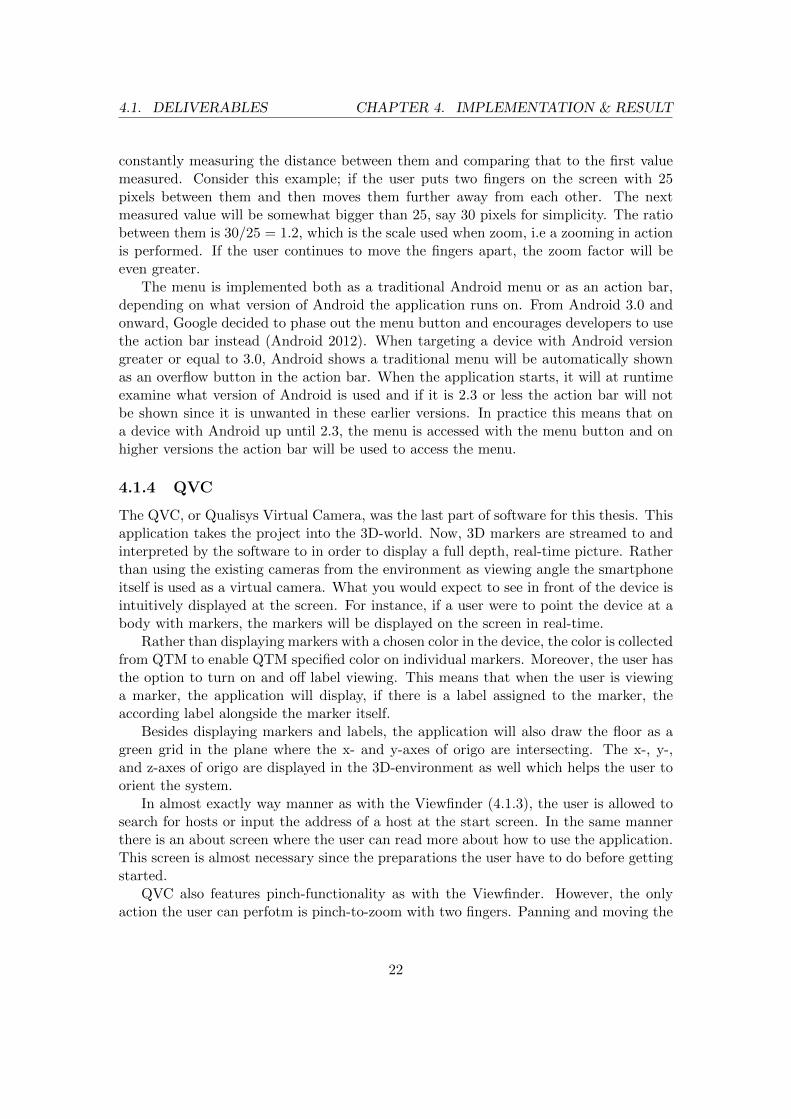
The QVC, or Qualisys Virtual Camera, was the last part of software for this thesis. Thisapplication takes the project into the 3D-world. Now, 3D markers are streamed to andinterpreted by the software to in order to display a full depth, real-time picture. Ratherthan using the existing cameras from the environment as viewing angle the smartphoneitself is used as a virtual camera. What you would expect to see in front of the device isintuitively displayed at the screen. For instance, if a user were to point the device at abody with markers, the markers will be displayed on the screen in real-time.
Rather than displaying markers with a chosen color in the device, the color is collectedfrom QTM to enable QTM specified color on individual markers. Moreover, the user hasthe option to turn on and off label viewing. This means that when the user is viewinga marker, the application will display, if there is a label assigned to the marker, theaccording label alongside the marker itself.
Besides displaying markers and labels, the application will also draw the floor as agreen grid in the plane where the x- and y-axes of origo are intersecting. The x-, y-,and z-axes of origo are displayed in the 3D-environment as well which helps the user toorient the system.
In almost exactly way manner as with the Viewfinder (4.1.3), the user is allowed tosearch for hosts or input the address of a host at the start screen. In the same mannerthere is an about screen where the user can read more about how to use the application.This screen is almost necessary since the preparations the user have to do before gettingstarted.
QVC also features pinch-functionality as with the Viewfinder. However, the onlyaction the user can perfotm is pinch-to-zoom with two fingers. Panning and moving the
22

4.1. DELIVERABLES CHAPTER 4. IMPLEMENTATION & RESULT
camera around is simply done by physically moving the device. The zoom feature isusable when you want a closer look of an object without having to move closer to it.
Figure 4.5 Screenshots of QVC in action
4.1.4.1 Implementation
The streaming of the markers works somewhat as in the viewfinder. The QTMAPI andit’s Java layer counterpart had to be rewritten just a bit. This was mainly to cover thenew aspects such as 3D-markers, colors and labels but we also had to create new functionsfor the rigid body (6DOF) streaming since support for this was not fully implementedin the QMAPI.
The largest difference in the data is that now each marker is streamed only once perframe, not once per frame and camera. Each frame that is streamed to the device containsinformation on each marker and its position in the system. Moreover, information aboutwhich markers have labels and if they have been assigned a special color has to befetched alongside the framestream. In the same manner the 6DOF information has tobe streamed separately.
The reason for streaming the information separately is because how the RT protocolis defined and how QTM act to commands. Although, this implementation doesn’t waitfor all information from a specific frame to arrive before drawing it, it simply draws whatis at hand at the moment. This may cause a latency issue when objects being drawnfrom different frames are intervened in one picture. However, this issue is not noticeable
23

4.1. DELIVERABLES CHAPTER 4. IMPLEMENTATION & RESULT
by the user since it should only be visible for a fraction of a second. If there are severelatency issues on the network the application will not work well anyhow.
Using the information streamed from QTM, the application draws a complete 3D-environment using OpenGL. Every item of the 3D-environment is measuring the samelength as in real life. The ground which is drawn as a green square net is actually drawnas 0.5m*0.5m squares, correlating to the real world. The x-, y- and z- axes are drawnwith a length of 1m. However, when the floor is only consisting of lines, the axes aredrawn with calculated coordinates which polygons are placed upon. This makes the axesstand out more and to make them distinguishable they are drawn in separate colors. Byeach axis the according letter (x, y or z) is also drawn for the users convenience.
Figure 4.6 Close-up of the x-axis
At the start of QVC, the coordinates of a sphere is calculated with the help oftrigonometric functions. With these coordinates, polygons and according normals arecalculated and stored for later use. This sphere is then what is used each time a markeris drawn. The normals are used in combination with a light source in order to createshading on the body of the sphere, giving the sphere 3D-look. With this, the specifiedcolor from QTM is added.
Figure 4.7 Close-up of a marker
For each marker label, a custom texture is drawn and stored with the label name.Using this for rendering later, allows us to just place the texture with the text on a
24

4.1. DELIVERABLES CHAPTER 4. IMPLEMENTATION & RESULT
flat object and position it alongside the according marker. In order for the label to bevisible from cameras position, a technique called billboarding is used. This means thatthe flat side of the object containing the text always have to face towards the camera.Knowing the position of the camera, each label and which way the camera is facing, thisis calculated accordingly and individually for each label.
Figure 4.8 Three markers with purple color and assigned labels
In order for the application to know where the smartphone that is to be used asvirtual camera is, the smartphone has to be defined as a rigid body in QTM. This isdone by fixating markers on the device itself. From a quick recording, the markers fixatedto the device can be selected and named - in this case ‘QVC’. Doing this will make thesystem identify the position and the angles of device. The device gets a center and x-, y-and z-axes. This rigid body is the last thing that has to be streamed to the application,and is called a 6DOF body. The information contained in a 6DOF body when streamedis the 3d-position of the body and a rotation matrix. The rotation matrix is used to turnthe camera accordingly with the device. Here, the z-axis of the 6DOF is identified as theangle the camera is looking, the y-axis points right from the perspective of the cameraand the x-axis indicates up. When this is applied the last thing to do is to position thecamera according to the 6DOF information.
Regarding the recommended placement of the markers on the rigid body (see Figure4.9), it is important to place the markers with some distance from the device. This is sothat the hand holding the device will not block the markers for the cameras that easily.Further, the markers should not be placed symmetrically and absolutely not in just oneplane. This is because placing markers symmetrically will allow for QTM to interpretthe axes of the body in several ways. For instance, imagine that the markers are placedin the same plane consisting of four markers forming a square. This could place the x-and y-axes at four different combinations with the z-axis able to point in two directionsorthogonal to the xy-plane. This makes for eight different possible interpretations of thebody’s coordinate system.
The reason for having four markers on the rigid body is that even if one marker iscompletely covered, the remaining three markers will still be enough for the cameras andQTM to recognize the position and angle of it. More markers placed on the body makes
25

4.2. INTERVIEWS CHAPTER 4. IMPLEMENTATION & RESULT
for a more stable recognition. However, for this purpose four markers are deemed to beenough.
Figure 4.9 A recommended configuration of a QVC rigid body with illustrated axes.
4.2 Interviews
The interviews showed that the remote application, like a normal external trigger isused to get closer to the measured subject. In some cases it is used to add events to thecapture timeline. The application highly resembles a normal external trigger (thoughwireless) in many aspects except one; response time. Since the regular external triggeruses an analog signal via a connected cord, its response time is more or less constant.In the case of the application, several factors like network lag and processing time maycause a variable response time.
According to the interviews, the Viewfinder is mostly helpful when mounting cam-eras. It is presented to customers as a side feature and showed when the systems areinstalled. Customers who use portable systems have greater use for the application thanother clients.
As for the QVC, the interviewees were more uncertain and speculated about it beingused when checking if markers are placed correctly. It may be presented to customersas a cool feature that shows the real-time capabilities of the system. A more specificpurpose may be found in the future and then the application may be used. Comparingthe QVC to the Viewfinder is hard since they are complementing each other. TheViewfinder is used while setting up a system and the QVC is used in an installed andcalibrated system. However there was one speculation about the QVC being helpful inthe event that real-time calculations of optimal camera placement is implemented. Thenyou might be able to use it to see in real-time where to move the cameras.
26

5 Discussion
In the discussion some different subjects regarding the helpfulness of the handheldapplications are assessed. Comparisons between the Android applications and theiriOS ditos are discussed and also some the known issues and limitations. Somedevelopment discussions are made with respect to NDK and finally the thoughts
on future work are presented.
5.1 Android adaptations of iOS applications
The Android platform and the iOS platform have some fundamental differences andtherefore the applications are bound to differ somewhat. In many cases, Android deviceshave (mostly in earlier version) a menu button, which is used to show a menu that cancontain additional alternatives and functionality than what is shown on the screen. InAndroid version 4.0 and forward this functionality is replaced by the action bar whichoffers similar functionality (Android 2012). In the Android apps, through either themenu or the action bar the menu alternatives are available, in contrast to the iOS appswhere the components often are placed directly on the screen. In general, the differentoperating systems have a certain feel about them and that is usually transferred totheir corresponding applications. In the development of the Android applications, theuser interfaces were created to be more suitable for the Android environment than theinterfaces in the iOS applications are. The menu adaptation is the most notable exampleof this.
In the viewfinder application the Android version features oval markers whereas theiOS one have only circles (even though the RT interface provides information about thediameter of the markers in both the x-axis and the y-axis). The Android applicationtakes both diameters into consideration and produces ovals but the iOS application usesonly one. In actuality this leads to a slight degradation of performance in the Androidapplication, since the coordinates for the oval shape has to be recalculated for everymarker in every frame, instead of scaling them in OpenGL. This performance issue isnot noticeable on the tested devices, but whether it would affect the performance inolder devices is not known. The advantage of using both diameters is that the markersin the application look like the markers in the 2D mode of QTM. This gives a highersense of conformity to the products.
The user interface of the remote iOS application does not consist of anything that
27
5.2. USEFULNESS OF THE APPLICATIONS CHAPTER 5. DISCUSSION
does not fit in the Android environment. Therefore the interface for the Android versionwas engineered to look more or less exactly like the iOS one. However since there is a bigvariety of different Android devices, the interface was constructed to fit many differentscreens.
In conclusion, the Android applications are made to be like the iOS applications andeven if there obviously is some differences in implementation, they use the same APIand offer the same functionality.
5.2 Usefulness of the applications
5.2.1 QTM Remote Control
The remote application contributes a lot in maneuvering a Qualisys system, when auser wants to be able to move around while controlling the capture and adding eventsto the timeline. The application provides even more freedom than a regular externaltrigger and do not restrict the user to the computer running QTM or by a crude cablelying around. Like the interviews suggest, the application can be inadequate if a certainresponse time is required, but otherwise it is less restricting. Another feature not presentin the regular trigger is the ability to name and save the captured data as files on thecomputer.
5.2.2 QTM Viewfinder
The Viewfinder’s contribution consists of the help it provides when configuring a system.This is the purpose for its creation and is also presented to the user as such. The userof the application is not bound to the computer to see where a camera points or howit is focused but can instead look at a device in their hand. When installing a systemfor a client, Qualisys employees utilize the Viewfinder to mount the cameras correctlyand configure their focus. By doing this, another feature of the system is shown to thecustomer and one can claim that this contributes to the sense of overall quality. Forcustomers that use portable systems which they move around a lot, the application canprove to be a smart feature that simplifies their work with installing the system. TheViewfinder is not a crucial part of the motion capture system, but it is a rather usefulone.
5.2.3 QVC
The usefulness of the QVC is much more uncertain than the two other applications.This is mainly due to the fact that the Viewfinder and remote applications have beenaround longer. Their advantages are already documented and they are already used inreal life situations. The QVC was developed as a kind of exploration project where the3D functionality of the real-time interface of QTM was to be used. Although the futurefor the QVC is unclear, the result of the interviews imply that it may be used whenplacing markers on a subject and making sure that they are in the right place. Another
28

5.3. JAVA AND NDK CHAPTER 5. DISCUSSION
speculation about the application’s future uses, involved configuration of the system byseeing in real-time where the cameras should be moved. To summarize, even though thefuture of the QVC is unknown it has potential for being used while maneuvering thesystem and there is also a slim chance that it can be used to configure the system.
When comparing the 2D functionality of the Viewfinder to the 3D functionality of theQVC, the first observation that comes to mind is that the applications does not reallyoverlap so the comparison itself is hard to make. The 2D functionality shows whatmarkers the different cameras see and however useful that may be when configuring thesystem, it does not really reveal any information about where the markers are placedin the 3D space. In turn, the 3D functionality does not say anything about what thedifferent cameras see. The extension to 3D presents a whole different set of features thanwhat is available in 2D. Even though one can claim that they are more exciting, onecannot say that they present any advantages.
5.3 Java and NDK
As mentioned before, an existing API in C was used during this thesis for all com-munication with QTM. The features and functions in the API, that are used by theapplications, were wrapped in Java using the NDK. The applications have some differ-ences when using the API and because of that, some differences in the wrapping exists.The main advantage with using the QTMAPI was that all the functionality of the RTprotocol was already present and usable. No work that focused on communication orlow level parsing of messages had to be done and focus was instead on the functionalityof the applications. The main disadvantage was the time it took to learn how to use theNDK in this environment and with the libraries needed.
To make a complete version of the API in Java would have been preferable, but thatwas not a part of this thesis. A complete and universal wrapping of the C library wouldhave been very time consuming and moderately complicated. Compared to wrapping thewhole C library, developing a pure Java API would have been more efficient but then themessage parsing and network communication would have been necessary. In summary,even though the NDK approach consumed a lot of time in the beginning of the thesis itmay have been more efficient than developing a pure Java API, since focus only lay onthe necessary features. Also, there is a high uncertainty regarding what problems mighthave arisen during development of the communication in a pure Java API.
5.4 Known issues and limitations
There are some issues that affect the performance of the applications and serve as lim-itations in the environment. In the Viewfinder and the QVC the data is streamed inreal-time from the server and this creates a problem that is out of the developers’ control,namely faulty network connection. If the applications are used on an unstable network,they may produce a very deficient performance. This can be highly frustrating for theuser and render the applications more or less unusable, however it is still up to the user
29

5.5. FUTURE WORK CHAPTER 5. DISCUSSION
to prevent it. Tests have concluded that a connection to a normal WLAN is usuallysufficient when running the applications, but sometimes high amounts of network trafficand insufficient range affects the performance. For the applications to perform at anabsolute maximum level, an ad-hoc WLAN is recommended.
Another limitation of the applications is that handheld devices tend to be small,especially phones. In order to make the applications bearable to use, all features mustbe easily accessible and have a good user interface. The challenge is to get all wantedfunctionality into the applications and still maintaining their usability. In the Qualisysmotion capture environment, there are a big variety of different features and functionsthat could be implemented for handheld devices so this limitation could easily be aproblem, but in the case of this thesis all wanted functionality was implemented withoutany difficulty.
An issue that might even be called a defect in the Viewfinder occurs when changingcamera modes. When the application was implemented, its behaviour was modeled afterthe iOS version. Because of this, when entering marker intensity or video mode all thecameras’ modes are changed. This was initially considered the correct behaviour sincethe iOS Viewfinder behaved the same way, but has since been deemed unwanted. Whenworking in with a system with many cameras, only one should change mode at a time.Since cameras only send marker information to QTM when in marker mode, changingfrom marker mode on all cameras would lead to no marker information whatsoever. Ina system with many cameras, losing marker information from one is not a terrible lossbut losing that information from all cameras is a problem. However this is usually onlya problem when multiple users of the system wants to do several things simultaneouslyand one uses the application.This problem cannot cause any serious harm since theapplication is not able to change camera mode during capture. Although, it can causea certain annoyance among the users.
5.5 Future work
As far as the remote control goes it is a remote application with all features that one couldimagine for that kind of adaptation. We do not think that there is so much developmentthat can be done in order to improve it; in its simplicity it fulfills its purpose.
As with the remote, there is not many useful features left to expand the Viewfinderwith. What was noticed during the course of this thesis was the issue with the afore-mentioned behaviour when changing camera mode. When the mode was to be changed,all cameras was told to change mode when in reality only the camera that is active onthe application is needed to be changed. Improving this feature would however implyupdating the iOS dito in order to maintain coherence.
The QVC has most potential in future work. Here there is a feature which wasexplored during the thesis but never fully completed, namely a augmented reality feature.This means using a real-time video stream from the camera on the device itself andmapping it against the 3D representation of the space. This make markers appear withlabels on actual bodies. Extending this feature further could be adding a 3D model on
30

5.5. FUTURE WORK CHAPTER 5. DISCUSSION
the image, mapped on the body with markers, making the model move in real-time. Thiscould be used for when recording movements in order to use them in games or movies,so that the user instantly gets feedback on what to expect from the recordings.
As mentioned before, the possibility of completely wrapping the QTMAPI into Javaexists. This would be preferred if there is another Java adaptation to develop in thefuture. Making the wrapper more general would allow for including the exact samelibrary in several applications, and to use it straight away. Today, features that wasnot used in the thesis are not represented in the Java QTMAPI counterpart and somefeatures have to be modified in order to work in other environments.
31

6 Conclusion
In this thesis, three Android applications for Qualisys motion capture systems weredeveloped using QTMAPI, a pre-existing C library. Two of the applications,Viewfinder and QTM Remote, already existed for the iOS platform. However,the third application, QVC, was completely new.
The viewfinder application and possibly the virtual camera can be used for configur-ing a system with the use of their real-time marker streaming capabilities, whereas theremote application is mainly used to maneuver the system by wirelessly controlling cap-tures. The virtual camera was developed as means to explore the 3D functionality of theQualisys real-time protocol and to evaluate possible advantages to the 2D functionalityof the Viewfinder. The QVC and the Viewfinder turned out to be very different appli-cations used in different contexts and therefore no advantages were identified. Howeverthe virtual camera introduces a new experience in the system and adds a new way todemonstrate its real-time capabilities. During the work with thesis, some limitations ofthe development were identified. The applications rely on the network performance togive an adequate experience and the full functionality of QTM would be to much tooimplement in an Android environment.
The future seems bright for the virtual camera, since it has big potential for furtherdevelopment in the form of augmented reality extensions. Perhaps even with real-timerendering of 3D models mapped to markers.
32

References
Android (2012), Android developers.URL: http://developer.android.com/ (2012-05-02)
BGR (2011), Apple and Google dominate smartphone space while others scramble.URL: http://www.bgr.com/2011/12/13/apple-and-google-dominate-smartphone-space-while-other-vendors-scramble/ (2012-05-24)
Cloete, T. & Scheffer, C. (2008), ‘Benchmarking of a full-body inertial motion capturesystem for clinical gait analysis’, Engineering in Medicine and Biology Society, 2008.EMBS 2008. 30th Annual International Conference of the IEEE; 20-25 Aug. 2008,Vancouver pp. 4579–4582.
Cohen, D., Lindvall, M. & Costa, P. (2004), ‘An introduction to agile methods’, InAdvances in Computers pp. 1–66. ed, Marvin Zelkowitz, Maryland Heights, MO:Elsevier, Academic Press.
Eclipse, C. (2010), C/C++ development tools.URL: http://market.eclipsesource.com/yoxos/node/org.eclipse.cdt.feature.group(2012-05-14)
Eclipse, F. (2012), About the eclipse foundation.URL: http://www.eclipse.org/org/ (2012-05-14)
Guihot, H. (2012), Pro Android apps performance optimization, [Electronic] Berkeley,CA: Apress.
Hashimi, S., Komatineni, S. & MacLean, D. (2010), Pro Android 2, [Electronic] NewYork: Springer-Verlag.
Helal, S., Bose, R. & Li, W. (2012), Mobile Platforms and Development Environments,[Electronic] Morgan and Claypool (Synthesis Lectures on Mobile and PervasiveComputing: 9).
33

REFERENCES
Martinsson, J. & Trost, R. (2010), Implementation of motion capture support in smart-phones, Master’s thesis, Chalmers University of Technology (Department of Com-puter Science and Engineering), Gothenburg.
Menache, A. (2010), Understanding Motion Capture for Computer Animation, Burling-ton, MA: Elsevier.
NDP, G. (2011), The NPD Group: For once-strong smartphone makers, 2011 was theyear of new beginnings.URL: https://www.npd.com/wps/portal/npd/us/news/pressreleases/pr 111213(2012-05-21)
Nilsson, L. (2012), QTM Real-time Server Protocol Documentation - v 1.10, Gothenburg:Qualisys AB.
Qualisys (2008), Qualisys Track Manager – QTM. Data acquisition software for motioncapture of any kind.
Qualisys (2011a), The art of motion capture.URL: http://www.qualisys.com/wp-content/uploads/2011/05/Qualisys companypresentation.pdf (2012-05-07)
Qualisys (2011b), Control systems.URL: http://www.qualisys.com/ (2012-04-11)
Qualisys (2012), Qtm remote.URL: http://itunes.apple.com/us/app/qtm-remote/id400683966 (2012-05-10)
Taylor, D. B. (2008), ‘A brief guide to writing a literature review’, Writing in the HealthSciences: a comprehensive guide 1(1).
Welch, G. (2002), ‘Motion tracking: no silver bullet, but a respectable arsenal’, ComputerGraphics and Applications, IEEE, 22(6), 24–38.
Writing, C. (2010), Literature reviews.URL: http://writingcenter.unc.edu/resources/handouts-demos/specific-writing-assignments/literature-reviews (2012-05-24)
xmlsoft (2009), The XML C parser and toolkit of gnome.URL: http://xmlsoft.org/ (2012-05-14)
34

A Appendix: Interview Questions
These are the questions asked during interviews with the Qualisys employees.
A.1 QTM Remote
• What is an external trigger normally used for?
• Is there any difference between the application and a normal external trigger?
• Is the remote an adequate replacement for a normal external trigger?
A.2 Viewfinder
• What does the viewfinder contribute to the motion capture system?
• How do you present the viewfinder to customers?
• How do customers usually use the application?
A.3 QVC
• In what ways can this application be useful to the system?
• Do you think that the application will be used in anyway in the future and how?
• What are your views on how the QVC differs from the Viewfinder and what pos-sibilities QVC may add compared to the Viewfinder?
35