masterlogic-200: specifications & technical data room instrumentation... · 1 masterlogic-200...
TRANSCRIPT

1 MasterLogic-200 Specifications and Technical Data
MasterLogic-200 Specifications and Technical Data
Release R200 Revision Date: May, 2010
Version 4.0
Release 200

Release R200 May, 2010 Version 4.0
2 MasterLogic-200 Specifications and Technical Data
Contents 1. INTRODUCTION ............................................................................................................. 4
1.1 OVERVIEW ................................................................................................................... 4 1.2 MASTERLOGIC-200 PLC SYSTEM ARCHITECTURE .......................................................... 5 1.3 GENERAL SPECIFICATIONS ............................................................................................ 7 1.4 CPU SUMMARY SPECIFICATIONS .................................................................................. 9 1.5 POWERFUL & VERSATILE CPU.................................................................................... 13 1.6 POWER SUPPLY MODULES (2MLI-CPUU) ................................................................... 32 1.7 POWER SUPPLY MODULES (2MLR-CPUH/#) ............................................................... 34 1.8 BASE OPTIONS (2MLI-CPUU) ..................................................................................... 35 1.9 BASE OPTIONS (2MLR-CPUH/#) ................................................................................ 38 1.10 I/O INTERFACE MODULES (2MLR-CPUH/#) ............................................................... 41
2. OPEN NETWORKS ........................................................................................................ 42 2.1 NETWORK SUMMARY SPECIFICATIONS ........................................................................ 42 2.2 FAST ETHERNET (FENET) ............................................................................................ 44 2.3 SERIAL COMMUNICATION (SNET) ................................................................................ 50 2.4 PROFIBUS-DP (PNET) .................................................................................................. 54
3. SOFTMASTER ............................................................................................................... 56 4. MODEL NUMBERS ....................................................................................................... 61
4.1 CPU MODULES ........................................................................................................... 61 4.2 I/O BASE, CABLES (2MLI-CPUU)................................................................................ 61 4.3 I/O BASE, I/O INTERFACE MODULES, CABLES (2MLR-CPUH) ....................................... 62 4.4 DIGITAL I/O MODULES ................................................................................................ 63 4.5 ANALOG I/O, HSC MODULES ...................................................................................... 65 4.6 COMMUNICATION MODULES ....................................................................................... 66 4.7 PROGRAMMING CABLES.............................................................................................. 66 4.8 SOFTWARE ENVIORNMENT .......................................................................................... 66 4.9 OTHERS...................................................................................................................... 67
Release R200 May, 2010 Version 4.0
3 MasterLogic-200 Specifications and Technical Data
Revision History
Revision Date Changes
1.0 September 2007 Initial Version
2.0 January, 2008 Included details on MasterLogic 200R
3.0 Sep, 2008 Updated MasterLogic 200R Specifications
4.0 May, 2010 Removed Experion PKS introduction, Included ML200R DC24V power supply , Removed Smart IO and Position Control Module
Legend for Change Column: A – Added D – Deleted M – Modified

Release R200 May, 2010 Version 4.0
4 MasterLogic-200 Specifications and Technical Data
1. Introduction 1.1 Overview
MasterLogic-200, Honeywell’s next generation Programmable Logic Controllers (PLC), adds power and robustness to logic-interlock-sequence batch control capabilities of Experion network. It is state of the art, compact yet powerful & versatile, cost-effective solution ideal for fast logic, sequential, and batch control applications
T The highlights of MasterLogic-200 PLC system are:
• Powerful & Versatile CPU (high speed / memory, IEC programming etc) • Compact footprint (Rack room, cabinet space saver, shipping costs
saver) • Modular options (power supply, range of I/O modules to suit your
configuration) • Flexibility in module assignment – any module can be installed in any
slot of any base without any restrictions. • Open networks (Fast Ethernet, UTP/Fiber-Optic, serial RS232C
/422/485) • Open protocols (Profibus-DP, MODBUS ASCII/RTU/TCP) • Peer-to-Peer networks (Dedicated Fast Ethernet on UTP/Fiber-optic) • Simulation Environment to test control strategies without hardware or
process connections. • Engineer-friendly software (Connection options, easy configuration &
trouble-shooting) • Diagnostics (System/Error Logs, system monitoring, network monitoring,
ping test, frame monitor) • Experion PKS & Experion HS Integration (PLC alarm/events, clock
synch, etc)

Release R200 May, 2010 Version 4.0
5 MasterLogic-200 Specifications and Technical Data
• Redundancy (CPU, Power, I/O network redundancy)
1.2 MasterLogic-200 PLC system architecture Redundancy options
MasterLogic-200 provides the control system designer with various redundancy architecture options that fits the requirement.
Fully Redundant system CPU Model: 2MLR-CPUH/# provides a fully redundant system:
• Redundant CPU • Redundant Power • Redundant I/O cable (ring topology with dual paths)
Non-redundant system For cost-effective applications, CPU Model: 2MLI-CPUU provides a fully non-redundant system:
• Non-redundant CPU • Non-redundant Power • Non-redundant I/O cable
Non-redundant CPU but Redundant Power and I/O cable A slight variation of the fully redundant architecture with only the master CPU of 2MLR-CPUH/# (excluding the standby CPU) offers the functionality of:
• Non-Redundant CPU • Redundant Power • Redundant I/O cable (ring topology with dual paths)

Release R200 May, 2010 Version 4.0
6 MasterLogic-200 Specifications and Technical Data

Release R200 May, 2010 Version 4.0
7 MasterLogic-200 Specifications and Technical Data
1.3 General Specifications
No. Item Specifications Related Standards
1 Ambient Temp. 0 ~ 55°C
2 Storage Temp. −25 ~ +70°C
3 Ambient humidity 5 ~ 95%RH (Non-condensing)
4 Storage humidity 5 ~ 95%RH (Non-condensing)
5 Vibration
Occasional vibration -
Frequency Acceleration Pulse width
Sweep Count
IEC61131-2
10 ≤ f <57Hz − 0.075mm
10 times each direction (X, Y and Z)
57 ≤ f ≤ 150Hz 9.8m/s2 − (1G) Continuous vibration
Frequency Acceleration Pulse width
10 ≤ f < 57Hz − 0.035mm
57 ≤ f ≤ 150Hz 4.9m/s2 − (0.5G)
6 Shocks
• Peak acceleration: 147m/s2
• Duration: 11ms (15G)
• Pulse wave type: Half-sine (3 times in each of X, Y and X directions)
IEC61131-2
7 Noise immunity
Square wave impulse noise ±1,500V
Electrostatic discharge Voltage: 4kV (Contact discharge)
IEC61131-2 IEC61000-4-2

Release R200 May, 2010 Version 4.0
8 MasterLogic-200 Specifications and Technical Data
Radiated electromagnetic field noise
27 ~ 500MHz, 10V/m
IEC61131-2, IEC61000-4-3
Fast transient /Burst noise
Classification Power supply
Digital/Analog Input/Output, Communication Interface
IEC61131-2 IEC61000-4-4
Voltage 2kV 1kV 8 Atmosphere Free from corrosive gases and excessive dust 9 Altitude Less than 2,000m
10 Pollution degree Less than 2
11 Cooling method Air-cooling
12 Agency Certifications
UL 508 Industrial Control Equipment 89/336/EEC, EMC Directive EN 50081-2, Emissions, Industrial EN 50082-2, Immunity, Industrial
Note: IEC (International Electrotechnical Commission) – An international civil community that promotes international cooperation for standardization of electric/ electro technology, publishes international standard and operates suitability assessment system related to the above. Pollution Degree – An index to indicate the pollution degree of used environment that determines the isolation performance of the device. For example, pollution degree 2 means the state to occur the pollution of non-electric conductivity generally, but the state to occur temporary electric conduction according to the formation of dew. Compliance to European Union Directives. This product has the CE mark and is approved for installation within the European Union and EEA regions. It has been designed and tested to meet the following directives: EMC Directive. This apparatus is tested to meet Council Directive 89/ 336/ EEC Electromagnetic Compatibility (EMC) using a technical construction file and the following standards, in whole or in part: • EN 50081- 2 EMC – Generic Emission Standard, Part 2 – Industrial Environment • EN 50082- 2 EMC – Generic Immunity Standard, Part 2 – Industrial Environment The product described in this document is intended for use in an industrial environment. Low Voltage Directive. This product is also designed to meet Council Directive 73/ 23/ EEC Low Voltage, by applying the safety requirements of EN 61131– 2 Programmable Controllers, Part 2 – Equipment Requirements and Tests.

Release R200 May, 2010 Version 4.0
9 MasterLogic-200 Specifications and Technical Data
1.4 CPU Summary Specifications
No. Item
Specifications Related
Standards 2MLI-CPUU Non-redundant
2MLR-CPUH/# Redundant or Non-
redundant
1 Program Execution methods Cyclic scan, Time-driven interrupts, Internal Memory interrupts
2 I/O control method Scan synchronous batch processing I/O (refresh method), Direct I/O method by program instruction
3 Program language Ladder Diagram, Sequential Function Chart, Structured Text, Instruction List (view only)
4 Number of instructions
Operator 18
Basic functions 136 + real number operation function
130 + real number operation function
Basic function block 43 41
Dedicated function block
Special function blocks, Process function blocks Dedicated communication function blocks (P2P)
5
Processing speed (Basic instruction)
LD 0.028µs/Step 0.042µs/Step MOV 0.084µs/Step 0.112µs/Step
Real number operation
±: 0.392µs (S), 0.924µs (D) ÷: 0.924µs (S), 2.254µs (D) x: 0.896µs (S), 2.240µs (D)
±: 0.602µs (S), 1.078µs (D) ÷: 1.106µs (S), 2.394µs (D) x: 1.134µs (S), 2.660µs (D)
S: Single real number D: Double real number
6 Program memory 7 MB
7 Max # I/O bases 8 (main + 7 extension) 31 8 Max # slots 96 372
9 Max base I/O
Using 64 ch DI/DO module 6,144 (64ch * 96 slots) 23,808 (64ch*372
slots) Using 32 ch DI/DO module 3,072 (32ch * 96 slots) 11,904 (32ch*372
slots)
10 Max I/O extension distance 15m (proprietary cable) 100m (UTP cable) 2km (Fiber-optic cable)
+open standards

Release R200 May, 2010 Version 4.0
10 MasterLogic-200 Specifications and Technical Data
11 Max Network / Remote I/O 128,000 128,000 Using network I/O
12 Flash Memory 16 MB
13 Data Memory Capacity
Symbolic Variable Area (A)
512 KB (Maximum, 256 KB retain settable)
Timer No point limit Time Range: 0.001 ~ 4,294,967.295 seconds (1,193hours)
Occupying 20 bytes of symbolic variable area per point
Counter No point limit Coefficient Range : -32,768 ~ +32,767
Occupying 8 bytes of symbolic variable area per point
Direct Variable
M 512 KB Fixed Area Variable
R 64 KB * 2
(%RW0~%RW32767) File Register (uses flash memory)
I
16 KB
(%IW0.0.0~%IW127.15.3)
Input Image Area
Q 16 KB (%QW0.0.0~%QW127.15.3)
Output Image Area
W 128 KB
(%WW0~%WW65535) File Register (uses flash memory)
Flag Variables
F 4 KB System Flag
K 18 KB (PID 256 loops) PID Flag
L 22 KB High Speed Link Flag
N 42 KB P2P Flag
U 32 KB Analog Refresh Flag as VAR_GLOBAL

Release R200 May, 2010 Version 4.0
11 MasterLogic-200 Specifications and Technical Data
14 Program Type Allocation
INIT task 1max Timer Interrupt tasks 32 max
Internal Device Interrupt tasks 32 max
Scan program Balance: 256 minus sum of above Total 256 max
15 CPU operation mode RUN, STOP, DEBUG 16 CPU restart mode Cold or warm restart
17 Self-diagnosis Watchdog timer, memory error, I/O error, battery error, power error, communication error etc.
18 Built-in Program port
RS-232C(1CH) Modbus slave supported via RS-232C port USB (1CH) @ 12MBPS
Note: Additional program connections via Ethernet & serial communication module (locate or remote)
19 Data storage method at power off Retain area configuration via Basic parameters
20 Current consumption (mA) 960 1173 (2MLR-CPUH/T) 1360 (2MLR-CPUH/F)
21 Weight (kg) 0.12 0.257 (2MLR-CPUH/T) 0.276 (2MLR-CPUH/F)
22
Redundancy Feature
Watchdog between CPUs NA Sync cable and Ring-type I/O Network
Data Backup NA 1Gbps Fiber Optic, max. 200m
Synchronization Method NA Configured in Redundancy parameter
Sync Cable Specification NA
62.5/125 Multi-mode Fiber LC type connector (Lucent Connector) Reture Loess : over 45db
Delay time for redundant NA Varies with data size

Release R200 May, 2010 Version 4.0
12 MasterLogic-200 Specifications and Technical Data
operation between CPUs - Default: 8.2ms / max. 80ms
Switchover Time NA 22ms
Operation delay during switchover NA
Max. time of delay time for redundant operation

Release R200 May, 2010 Version 4.0
13 MasterLogic-200 Specifications and Technical Data
1.5 Powerful & Versatile CPU
High Speed Facilitated by a powerful state of the art processor (NGP1000), MasterLogic-200 CPU provides high speed execution of program instructions and backplane/ communication data transfers. In addition, dedicated intelligent communication modules (Ethernet, Serial, Profibus etc) offer co-processing assistance to the main controller CPU.
High Memory High memory of MasterLogic-200 CPU combined with high speed & huge I/O capacity feature provides a robust platform for efficient performance in large applications. Summary specification for CPU Models: 2MLI-CPUU & 2MLR-CPUH/#
Memory Specification Memory size Remarks
Total Memory 25 MB
Built-in Flash Memory 16 MB For program & data backup
Program Memory (Incl. System Memory)
7 MB For program execution, upload, system parameters, history logs
Data Memory 2 MB Direct variables & Symbolic (named) variables
Free slot assignment
This is good news to engineers handling base/slot assignment. MasterLogic-200 poses no restriction whatsoever. Any module type i.e. digital I/O, analog I/O, HSC (pulse input), RTD, Thermocouple, and even communication modules (i.e. Ethernet, Serial, Profibus-DP, DeviceNet) can be freely assigned to any base/slot irrespective of base #, Slot #.

Release R200 May, 2010 Version 4.0
14 MasterLogic-200 Specifications and Technical Data
Without any restriction, any of the above modules (except for Ethernet module) can also be installed in remote I/O bases located far away (by using FO network of 2MLR-CPUH/#).
Large I/O capacity MasterLogic-200 accommodates a huge I/O capacity through base I/O and remote/network I/O capabilities. The I/O capacity details are tabulated as follows:
Model: 2MLI-CPUU (Non-redundant)
Model: 2MLI-CPUU Qty Remarks
Max # of bases 8 1 main base + 7 extension bases
Max # of slots 96 12 slots * 8 base = 96 slots
Base I/O 6,144 points
Using 64 ch DI/DO module
96 slots * 64 ch = 6,144 points
3,072 points
Using 32 ch DI/DO module
96 slots * 32 ch = 3,072 points
Network & Remote I/O (Max I/O memory)
128,000 points
Using network I/O
Model: 2MLR-CPUH/# (Non-redundant or Redundant)
Model: 2MLR-CPUH/# Qty Remarks
Max # of I/O bases 31 On either Ethernet or Fiber-optic networks
Max # of slots 372 12 slots * 31 base = 372 slots
Base I/O 23,808 points
Using 64 ch DI/DO module
372 slots * 64 ch = 23,808 points
11,904 points
Using 32 ch DI/DO module
372 slots * 32 ch = 11,904 points
Network I/O (Max I/O memory)
128,000 points
Using network I/O modules.

Release R200 May, 2010 Version 4.0
15 MasterLogic-200 Specifications and Technical Data
High Speed Synchronization
In redundant CPU systems, a dedicated high speed 1Gigabit fiber-optic link between primary and backup CPU ensures efficient synchronization of data and program memory areas. Upon failure of the primary CPU, the control switches over to the backup CPU bumplessly in less than 50 msec.
IEC 61131-3 Standard Programming Languages MasterLogic-200 PLCs do not restrict the control engineers with a solitary ladder programming (LD) language. Their work is made easier with a choice of IEC standard programming languages. Each of the IEC 61131-3 standard programming language is designed for a specific application.
Ladder (LD) MasterLogic-200 provides a friendly ladder (LD) programming editor, best suited for relay logic / interlocks with timers and counters. The same editor serves as online monitoring display for trouble-shooting situations.
Sequential Function Chart (SFC) However, ladder would be cumbersome for the engineer to build strategies for sequencing/batching applications with state/transition conditions. Sequential Function Chart (SFC) visual programming editor best suited for that purpose is provided.
Online Monitoring Contact On

Release R200 May, 2010 Version 4.0
16 MasterLogic-200 Specifications and Technical Data
Structured Text (ST) Likewise, so as to build a own library of user-defined function blocks or being accustomed to computer languages like BASIC, PASCAL etc, the engineer would be inclined to pick Structured Text (ST) language as the right choice.

Release R200 May, 2010 Version 4.0
17 MasterLogic-200 Specifications and Technical Data
Instruction List (IL – View only mode) A mnemonic assembly-type programming language (currently in view only mode) to assist to cross-verification of ladder program sequences.
Flexibility to mix & match MasterLogic-200 empowers the control engineer with flexibility to mix & match different languages in a single CPU with modular programs, each serving a specific requirement typical to industrial process control situations.
Programming Language Remarks
LD (Ladder) Relay logic / interlocks
SFC (Sequential Function Chart) State / Transition diagrams for sequential/batch applications
ST (Structured Text) BASIC, PASCAL like programming language
FB (Function Block) To be used / embedded in other programming languages e.g. LD, SFC, ST
IL (Instruction List) View only mode of LD instructions

Release R200 May, 2010 Version 4.0
18 MasterLogic-200 Specifications and Technical Data
Program Types & Modular Programs MasterLogic-200 allows modularizing the whole control strategy for the PLC into max. 256 easily manageable sub-programs, executed either cyclically once every scan in the order or interrupt driven based on timer or memory conditions.
Program Type Max # Task # When executed?
INIT Program 1 Executed once during PLC startup
Timer Interrupts 32 0~31 Executed when timer interval elapses (configurable @ 1msec resolution)
Device Interrupts 32 64~95 Executed when configured internal memory condition occurs
Scan Programs Balance Executed once every scan
Total 256 Note: Task ID 32~63 reserved for future use (I/O interrupt conditions)
Cold or Warm Restart Options MasterLogic-200 provides two CPU restart modes, cold or warm options to fit the restart circumstances.
Mode
Parameter Cold Restart Warm Restart
Default Initializing as ‘0’ Initializing as ‘0’
Retain Initializing as ‘0’ Maintaining the previous value
Initialization Initializing as a user-defined value
Initializing as a user-defined value
Retain and initialization
Initializing as a user-defined value Maintaining the previous value

Release R200 May, 2010 Version 4.0
19 MasterLogic-200 Specifications and Technical Data
IEC data types
The following are IEC standard data types supported by MasterLogic-200 programs in accessing direct & symbolic (named) variables. Variables can be defined as local (accessible only within the program) or global variables (accessible across all programs).
Data Category Data types supported
Bit BOOL
Byte BYTE
Word WORD, DWORD, LWORD
Integer SINT, INT, DINT, LINT
Unsigned Integer USINT, UINT, UDINT, ULINT
Real REAL (Single precision), LREAL (Double precision)
Date & Time TIME, DATE, TIME_OF_DAY, DATE_AND_TIME
Text Character STRING
Array ARRAY (3-dimensional arrays, max array size of 32767 elements)
User-defined data type STRUCT
Function Block instances FB_INST

Release R200 May, 2010 Version 4.0
20 MasterLogic-200 Specifications and Technical Data
Three-dimensional arrays Array variables are extremely useful to a programmer to store a series of related data items. For example, an array variable Tank_Level[0..9] can be used to store level values of a max of 10 similar tanks typically using “for loop” command.
Function Block & Instruction Library
Drastically reducing engineering time, a vast library of instructions & function blocks is pre-built and packaged with MasterLogic-200 system. Here is an overview of the function block library available for the control engineer.
Function Type Functions / Function Blocks
Input Contacts NC/NO Contact , ±Transition contacts +

Release R200 May, 2010 Version 4.0
21 MasterLogic-200 Specifications and Technical Data
Coils Coil/Negated coils, Set/Reset coils (latch), ±Transition sensing coils
+
Data type conversions
Bool_to_*, Byte_to_*, Word_to_*, Int*_to_*, UInt*_to*, Real*_to_*, Time_to_*, Date_to_*, String_to_*, BCD_to_*, *_to_BCD
Bit functions AND, OR, NOT, XOR, XNR, SHL, SHR, ROL, ROR etc.
ARRAY functions
Move, Rotate, Compare, Fill, Average, Shift etc.
Comparison Functions
GT, EQ, GE, LT, LE, NE
Timer On Delay, Off Delay, Pulse Timers…
Counter Count up, Count Down, Count Up/Down…
String Functions CONCAT, LEFT, RIGHT, MID, INSERT, DELETE, REPLACE...
Process Control Average, Delay, Limit, Rate, Summer, Totalizer, Analog_Selector, Function Generator, Lead Lag PID with auto tuning, Cascade control , Ratio Control, Alarm, Ramp
Stack Functions LIFO_***, FIFO_***…
Date & Time functions
Multiply, Subtract, Divide, Add functions on date and time variables
Mathematical functions
Exponential, Degree/Radian, ADD/MUL/DIV/SUB, ABS, MOD, Trignometric (SIN, COS, TAN…), SQRT, LOG…,
Select Functions Max, Min, Multiplex…
System Control Functions
SCON, DUTY, STOP, ESTOP, DIREC_IN/O, Watchdog reset, Master Clear, Semaphore etc.
+
Basic instructions in ladder program

Release R200 May, 2010 Version 4.0
22 MasterLogic-200 Specifications and Technical Data
Symbolic (Named) Variables with auto memory allocation A significant amount of data memory, as high as 512KB, is allocated for Symbolic variables in MasterLogic-200 CPU. This is equivalent to 50% of the total data memory, thus intensifying the utilization of auto memory allocation. The control engineers can simply building named variables circumventing the hassles of manual memory allocation and derive the convenience of letting the CPU automatically allocate memory according to the data types. This eliminates human lapses involved in duplicate assignment, unused memory etc.
Retention Memory Portions of data memory area provide (non-volatile) memory retention function.
• %R (File Register) memory area comprising 2 blocks of 64KB each serving always as non-volatile memory for the engineers. Data stored here will be retained even upon power failure to CPU and during cold or warm restart options. The data in this area can be cleared only by operating the CPU switch D.CLR for > 3 sec or upon battery failure
Release R200 May, 2010 Version 4.0
23 MasterLogic-200 Specifications and Technical Data
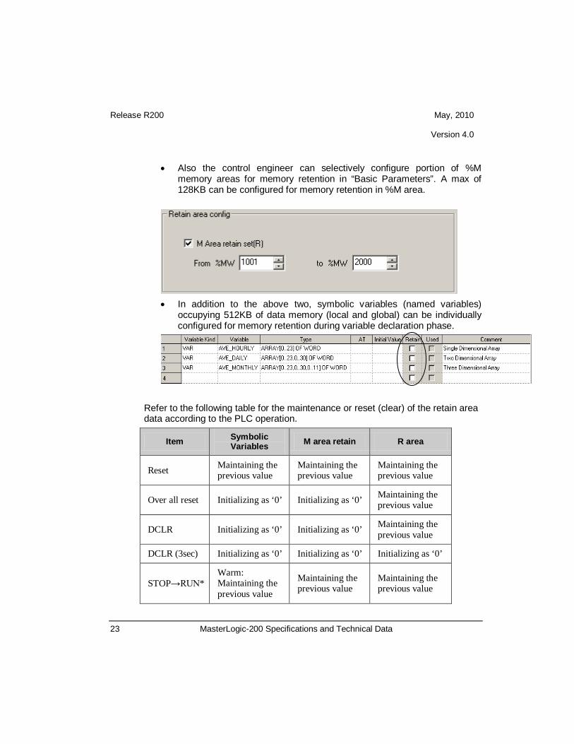
• Also the control engineer can selectively configure portion of %M memory areas for memory retention in “Basic Parameters”. A max of 128KB can be configured for memory retention in %M area.
• In addition to the above two, symbolic variables (named variables)
occupying 512KB of data memory (local and global) can be individually configured for memory retention during variable declaration phase.
Refer to the following table for the maintenance or reset (clear) of the retain area data according to the PLC operation.
Item Symbolic Variables M area retain R area
Reset Maintaining the previous value
Maintaining the previous value
Maintaining the previous value
Over all reset Initializing as ‘0’ Initializing as ‘0’ Maintaining the previous value
DCLR Initializing as ‘0’ Initializing as ‘0’ Maintaining the previous value
DCLR (3sec) Initializing as ‘0’ Initializing as ‘0’ Initializing as ‘0’
STOP→RUN* Warm: Maintaining the previous value
Maintaining the previous value
Maintaining the previous value

Release R200 May, 2010 Version 4.0
24 MasterLogic-200 Specifications and Technical Data
Cold: Initializing as ‘0’
* Cold Restart Mode if the program is downloaded
Please refer to Cold or Warm Restart Options section to know more about memory retention functions.
Online Maintenance Functions
Hot-swapping Any faulty I/O module can be swapped online with a new one without having to stop a running CPU. There are two methods:
o By operating a switch M.XCHG in CPU module (Available for 2MLI-CPUU only)
o By running a software wizard in SoftMaster
Online Editing Any part of the PLC program can be edited online when CPU is running & the new program can be downloaded to the CPU without having to stop the CPU. SoftMaster allows an intermediate step of downloading the modified program to CPU and monitor the outcome. The programmer can continue to make changes if required without quitting the

Release R200 May, 2010 Version 4.0
25 MasterLogic-200 Specifications and Technical Data
session.
Fault Mask Fault Mask enables program to continue uninterrupted even if a module error occurs. Fault Mask can be set for any base/slot module either by • SoftMaster software tool • Program instruction setting fault mask flag Only the faulty module stops operating while the overall system continues to operate due to Fault Mask settings. If there is no error in the module, CPU works normally with this setting.
Skip I/O Skip I/O setting for any base/slot module instructs the CPU to skip processing of specified I/O module(s). The input image (%I) area would not be refreshed for those modules and output image area will not be transferred to the actual module.
Force I/O This function enables the control engineer to force either ON or OFF values to digital input or output locations in I/O bit image areas.

Release R200 May, 2010 Version 4.0
26 MasterLogic-200 Specifications and Technical Data
Data Trouble-shooting Functions
Data Tracing This is one of unique features of MasterLogic PLC. Data tracing works at CPU level, quite different from the trend monitoring feature usually available at software level in many PLCs. Configure the trace parameters (trigger condition, trace variables, sampling size) and trouble-shoot the variables in trend graphic or tabular format.
Release R200 May, 2010 Version 4.0
27 MasterLogic-200 Specifications and Technical Data
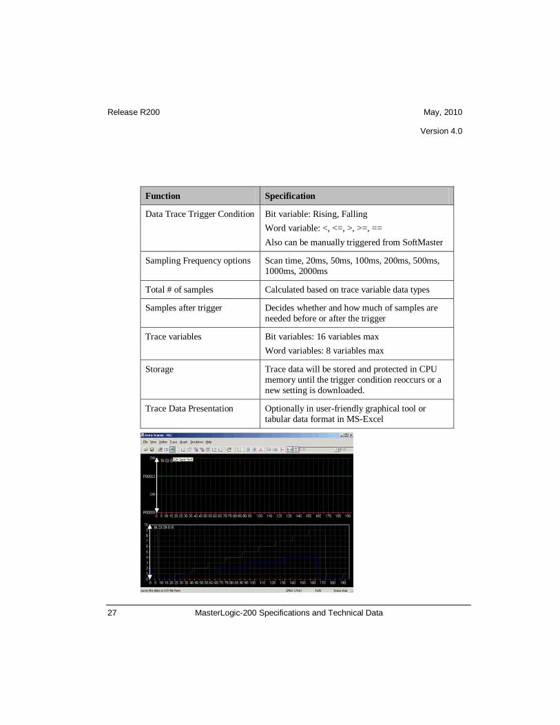
Function Specification
Data Trace Trigger Condition Bit variable: Rising, Falling Word variable: <, <=, >, >=, == Also can be manually triggered from SoftMaster
Sampling Frequency options Scan time, 20ms, 50ms, 100ms, 200ms, 500ms, 1000ms, 2000ms
Total # of samples Calculated based on trace variable data types
Samples after trigger Decides whether and how much of samples are needed before or after the trigger
Trace variables Bit variables: 16 variables max Word variables: 8 variables max
Storage Trace data will be stored and protected in CPU memory until the trigger condition reoccurs or a new setting is downloaded.
Trace Data Presentation Optionally in user-friendly graphical tool or tabular data format in MS-Excel

Release R200 May, 2010 Version 4.0
28 MasterLogic-200 Specifications and Technical Data
User-defined Custom Events Configure user-defined custom event settings and download to CPU for logging events in database. Trigger conditions can be any bit variable, direct or symbolic. Also 16 variables (bit, word, real data type) can be associated to the event whose current value will be captured when the event is triggered.

Release R200 May, 2010 Version 4.0
29 MasterLogic-200 Specifications and Technical Data
Function Specification
Max # of variables that can be configured for custom event trigger
10 variables
Associated variables Max 16 variables (bit, word, real data type) can be associated to the event for current value capture
Max buffer size for custom event capture in CPU
300 events
Variable type for event trigger Only bit variables
Trigger condition Rising, Falling, Transition options
Trigger Detection Speed Scan time (milli-sec time stamping)
Event category Information, Critical, Alarm
Applications Trouble-shooting, Limited SOE
RTC (Real-time Clock) MasterLogic-200 has a built-in clock (RTC) which runs on battery even in case of power failure. The RTC can be monitored & updated, if necessary, through:
o SoftMaster (manual command from GUI) o Experion PKS server (auto sync with server clock) o Programming instructions
All system events, custom events & errors logs are time stamped using RTC.

Release R200 May, 2010 Version 4.0
30 MasterLogic-200 Specifications and Technical Data
Debug Modes
MasterLogic-200 program can be optionally started in DEBUG mode for any specific trouble-shooting. Breakpoints can be either: • Manually set on / removed from any line of the program regardless of the
programming language used. • Set for trigger by internal memory variable or scan cycle count conditions PLC History - System alarm & events MasterLogic-200 CPU records four different types of system alarms & events occurring in PLC.
Event type Description Buffer Size in CPU
Error Log Any error occurring in system – error code, timestamp, error details
2048 events

Release R200 May, 2010 Version 4.0
31 MasterLogic-200 Specifications and Technical Data
System Log Operation history of key system events with timestamp
2048 events
Mode change Log CPU mode changes, RUN/STOP/DEBUG with timestamp
1024 events
Power shutdown Log Power ON/OFF, failure events with timestamp
1024 events
The event buffer in CPU is limited and FIFO cyclic. But all the above 4 types of PLC alarms & events can be archived in Experion and consolidated with Experion system alarms & events display. Please refer to MasterLogic-Experion Integration specification for further details.

Release R200 May, 2010 Version 4.0
32 MasterLogic-200 Specifications and Technical Data
1.6 Power Supply Modules (2MLI-CPUU) There are four power supply modules with different specifications to choose from, according to the site requirements e.g. flexible voltage input range, DC input power, output voltages and current rating. The below specifications are applicable for CPU model: 2MLI-CPUU
Item 2MLP-ACF1 2MLP-ACF2 2MLP-AC23 2MLP-DC42
Input
Rated input voltage AC 100V – AC 240V AC 200V – AC 240V DC 24V Input voltage range AC 85V ~ AC 264V AC 170V ~ AC 264V - Input frequency 50 / 60 Hz (47 ~ 63 Hz) - Inrush current 20 APeak or less 80APeak or less Efficiency 65% or more 60% or more Input fuse Built-in (user no change), UL standard (Slow Blow Type) Allowed instantaneous interruption
10 ms and shorter
Output1
Output voltage DC 5V (±2%) DC5V (±2%)
Output current 3.0A 6.0A 8.5A 6.0A
Over current protect 3.2A or more 6.6A or more 9.0A or more 6.6A or more
Over voltage protect 5.5V ~ 6.5V
Output2
Output voltage DC 24V (±10%)
- - Output current 0.6A Over current protect 0.7A or more Over voltage protect None
Relay Output
Application RUN contact
Rated switching voltage/current DC 24V, 0.5A
Minimum switching load DC 5V,1㎃

Release R200 May, 2010 Version 4.0
33 MasterLogic-200 Specifications and Technical Data
Battery Specifications
Item Specifications
Nominal voltage/current DC 3.0V / 1,800mAh
Warranty period 5 years (at ambient temperature)
Purpose Program and data backup, RTC operation when Power-OFF Specification Manganese dioxide lithium battery Outer dimension (mm) φ 17.0 X 33.5mm
Response time OFF→ON/ ON→OFF: 10㎳ or less/12㎳ or less
Life Mechanical life: 20 million and more times Electrical life: rated switching current: 100 thousand and more times
Voltage indicator Output voltage normal, LED ON
Cable specification 0.75 ~ 2mm
Compressed terminal
2
RAV 1.25 - 3.5, RAV 2 - 3.5
Weight 0.4kg 0.6kg 0.5kg

Release R200 May, 2010 Version 4.0
34 MasterLogic-200 Specifications and Technical Data
1.7 Power Supply Modules (2MLR-CPUH/#) There are four power supply modules with different specifications to choose from, according to the site requirements e.g. flexible voltage input range, DC input power, output voltages and current rating.
Item 2MLR-AC12 2MLR-AC22 2MLR-AC13 2MLR- AC23 2MLR-DC42
Input
Rated input voltage 110 VAC 220 VAC I10 VAC 220 VAC 24 VDC
Input voltage range 85V~132VAC 176V~264VAC 85V~132VAC 176V~264VAC 19.2 ~ 28.8 VDC
Input frequency 50 / 60 Hz (47 ~ 63 Hz) -
Max. input power 110 VA / 42 W 176 VA / 72 W -
Inrush current 20A peak and lower (within8 ㎳ ) 80A peak and lower
Efficiency 65% or higher
Input fuse Built in(not replaceable by a user) - AC power: 250V / 3.15A ( Time-lag Type ) UL approved
- DC power: 125V/10A (Time-lag type) UL approved
Allowed instantaneous interruption
Within 20 ㎳
Output
Output voltage 5VDC (±2%) Output current 5.5A 8.5A 7.5A Output power 27.5W @ 55℃ 46.75W @ 55℃ 37.5W @ 55℃ Over current protection 6.0 A ~ 13.0 A 9.3 A ~ 17.0 A 9.0 A~17.0 A
Relay Output
Purpose RUN contact (refer to 8.2) Rated switching voltage/current 24VDC, 0.5A
Min. switching load 5VDC, 1㎃
Response time Off→On/ On→Off: 10㎳ and lower/12㎳ and lower
Life Mechanical life: 20 million and more times, electrical life: rated switching current: 100 thousand and more times
Voltage status display LED On when output voltage is normal
Specification of cable 0.75 ~ 2 mm
Available clamped terminal
2
RAV1.25-3.5, RAV2-3.5 Dimension (W x H x D mm) 55 x 95 x 90 55 x 95 x 110
Weight 326g 382g 334g 384g 417g

Release R200 May, 2010 Version 4.0
35 MasterLogic-200 Specifications and Technical Data
Applied base and install position Power part of basic/extension base
Battery Specifications
Item Specifications
Nominal voltage/current DC 3.0V / 1,800mAh
Warranty period 5 years (at ambient temperature)
Purpose Program and data backup, RTC operation when Power-OFF Specification Manganese dioxide lithium battery
Outer dimension (mm) φ 17.0 X 33.5mm
1.8 Base options (2MLI-CPUU) There are four I/O base options to select from: 4 slot, 6 slot, 8 slot & 12 slot bases. The below specifications are applicable only for CPU model: 2MLI-CPUU
Main CPU base options
Expansion I/O base options
Model Item
2MLB-M12A 2MLB-M08A 2MLB-M06A 2MLB-M04A
No of Modules 12 modules 8 modules 6 modules 4 modules
Dimension (mm) 426 X 98 X 19 318 X 98 X 19 264 X 98 X 19 210 X 98 X 19
Weight (kg) 0.54 0.42 0.34 0.28

Release R200 May, 2010 Version 4.0
36 MasterLogic-200 Specifications and Technical Data
Model Item
2MLB-E12A 2MLB-E08A 2MLB-E06A 2MLB-E04A
No of Modules 12 modules 8 modules 6 modules 4 modules
Dimension (mm) 426 X 98 X 19 318 X 98 X 19 264 X 98 X 19 210 X 98 X 19
Weight (kg) 0.59 0.47 0.39 0.33
Expansion I/O cable options
Model Item
2MLC-E041
2MLC-E061
2MLC-E121
2MLC-E301
2MLC-E501
2MLC-E102
2MLC-E152
Length (m) 0.40 + 0.60 1.20 3.00 5.00 10.00 15.0
Weight (kg) 0.15 0.16 0.22 0.39 0.62 1.20 1.80 * The total cable length between the CPU and the farthest I/O expansion base should not exceed 15m.

Release R200 May, 2010 Version 4.0
37 MasterLogic-200 Specifications and Technical Data

Release R200 May, 2010 Version 4.0
38 MasterLogic-200 Specifications and Technical Data
1.9 Base Options (2MLR-CPUH/#)
The above diagram demonstrates co-existence of both local I/O base and remote I/O base (i.e. UTP and fiber-optic cables) in a single I/O network. Please note that only FEnet module can reside on CPU Base. FEnet module can not be installed on the Expansion base. In redundant system employing CPU model: 2MLR-CPUH/#, Local I/O bases can communicate with the CPU via Industrial Ethernet using UTP CAT5 cable traveling up to a max 100m distance.

Release R200 May, 2010 Version 4.0
39 MasterLogic-200 Specifications and Technical Data
Remote I/O bases as far as 2km can communicate with the CPU on fiber-optic networks available in both CPU as well I/O base communication slave modules.
Main CPU base options
Expansion I/O base options
Model Item
2MLR-E12P
No of Modules 12 modules
Dimension (mm) 481 X 98 X 19
Current Consumption (mA) 220
Weight 0.59
Model Item
2MLR-M06P
No of Modules 6 modules
Dimension (mm) 346 X 98 X 19
Current Consumption (mA) 211
Weight 0.34 kg

Release R200 May, 2010 Version 4.0
40 MasterLogic-200 Specifications and Technical Data

Release R200 May, 2010 Version 4.0
41 MasterLogic-200 Specifications and Technical Data
1.10 I/O Interface Modules (2MLR-CPUH/#)
Item Specification
Remarks 2MLR-DBSF 2MLR-DBST 2MLR-DBSH
Media Optical Electrical Mixed
Max. distance between Extension bases
Optical (2km) Electrical (100m)
Optical (2km)
Electrical (100m)
Cable Spec
62.5/125 Multi-mode Fiber LC type connector (Lucent Connector) Return Loss : over 45db
Loader connection Extension drive USB
Range of station no. 1 ~ 31 (other no. will generate an error ) No.0: not
available
Install position CPU parts(CPU0 connector) in extension base
Weight (g) 99 100 102

Release R200 May, 2010 Version 4.0
42 MasterLogic-200 Specifications and Technical Data
2. Open networks 2.1 Network Summary Specifications
A wide range of open networking capability makes adds versatility to MasterLogic-200 PLC’s scalable architecture. System engineers have an array of choices and features to design & construct a system architecture that is not just meeting the application but also renders high performance and bandwidth for future expansions.
Fast Ethernet Serial Comm Profibus-DP
FEnet Snet Pnet
Modules 2MLL-EFMT (T.P) 2MLL-EFMF (F.O)
2MLL-CH2A 2MLL-C22A 2MLL-C42A
2MLL-PMEA
Transmission Speed 100/10Mbps 300 ~ 11.5kbps
9.6k ~12Mbps
Physical Layer IEEE802.3U - 100baseTx (T.P), 100baseFx (Fiber-Optic - Multi Mode)
RS232C / RS422 / 485 RS485
Distance 100m (Switch/Node , UTP/STP) 2Km (Switch/Node , Fiber Optic)
Max 500m (RS422/485) Max 1.2Km
Max # of nodes 64 32 126 (32/segment)
Service / Protocol
HSL √ (Peer-to-Peer) - √
(Profibus-DP)
MLDP √ (Experion Interface) - -
Modbus slave √ (MODBUS TCP slave)
√
(MODBUS RTU/ASCII
slave)
-
P2P √ (MODBUS TCP master, User defined Protocol master)
√
(MODBUS RTU/ASCII master, User defined Protocol master)
-

Release R200 May, 2010 Version 4.0
43 MasterLogic-200 Specifications and Technical Data
SoftMaster I/F √ √
Configuration Software SoftMaster-NM SoftMaster-NM & Sycon
No of communication modules per CPU
Max 24 communication modules per CPU (Max 12 HSL services & 8 P2P services per CPU)
Network Diagnostics Auto-scan, Ping Test, Frame Monitor, Link Monitor, Loop back (as applicable)
HSL Service High Speed Link can be defined as a communication service that performs bi-directional data transfers between:
o Two or more MasterLogic-200 PLCs (Peer-to-Peer) o MasterLogic-200 and Profibus-DP devices (Pnet)
There can be a maximum of 12 HSL services per MasterLogic-200 CPU. Each HSL service can have a max of 128 blocks (either SEND or RECEIVE) and each block can handle of max of 200 words data size.
P2P Service (point to point) P2P service can be defined as a communication service that performs:
o MasterLogic acting as MODBUS master and third-party open devices as MODBUS slave (MODBUS RTU/ASCII master on serial or MODBUS TCP master on Ethernet)
o MasterLogic acting as User-Defined Communication master and third-party proprietary devices as slave (both serial and Ethernet TCP-IP)
There can be a maximum of 8 P2P services per MasterLogic-200 CPU. Each P2P service can have a max of 64 blocks (either READ or WRITE).

Release R200 May, 2010 Version 4.0
44 MasterLogic-200 Specifications and Technical Data
2.2 Fast Ethernet (FEnet)
Overview Open standard (IEEE802.3U) high speed Ethernet (FEnet) modules facilitate inter-connecting MasterLogic PLCs with either higher level computers or other peer PLCs on industrial Ethernet network. Network control uses industry standard Carrier Sense Multiple Access with Collision Detection (CSMA/CD) protocol. Two types of modules are available to choose depending on the distance and cabling philosophy.
o Twisted pair (UTP/STP-CAT5) media with RJ45 connector (100m) o Fiber-optic (x62.5/125um, Multi-mode) media with SC connector (2km)
They provide a variety of services / functions / protocols:
o Peer-to-Peer integration with other MasterLogic PLCs o Experion integration via special MasterLogic Dedicated Protocol (MLDP) o MODBUS TCP-IP master / slave protocols o SoftMaster Interface o User-defined Protocol for interfacing with third-party devices
Concurrent services The above services are based on TCP-IP & UDP-IP protocols and thus many of the above processes can be concurrent, i.e. running at the same time in a single FEnet module. For example, a single FEnet module can be used for a) peer-to-

Release R200 May, 2010 Version 4.0
45 MasterLogic-200 Specifications and Technical Data
peer integration with other PLCs, b) Experion integration c) MODBUS TCP-IP master protocol d) SoftMaster I/F all at the same time. However, performance could be limited depending on the load.
Specifications Fast Ethernet Modules 2MLL-EFMT 2MLL-EFMF
Ethernet Standard IEEE802.3U
Protocol TCP-IP, UDP-IP
Network Control Protocol (Access Method)
CSMA/CD
Software Firewall IP address settings in SoftMaster-NM
Public Network Access DNS server and Gateway IP address setting
Dynamic IP address for ADSL DHCP protocol
Highway Topology (Transmission Method)
Baseband
Transmission Speed 10/100 Mbps 100 Mbps
Physical Layer 100baseTx (T.P) 100baseFx (Fiber-Optic)
Media UTP/STP, CAT5 (RJ45 connector)
x62.5/125um, Multi-mode, SC connector
Transmission Distance 100m (Switch/Node , UTP/STP)
2Km (Switch/Node , Fiber Optic)
Max # of nodes 64
Service / Protocol
HSL √
(Peer-to-Peer High Speed Link with other MasterLogic PLCs)
HSL Send/Receive blocks 200 words / block, (Max. 128 blocks)
MLDP √
(Experion Interface – MasterLogic Dedicated Protocol)
Modbus TCP slave √
(MODBUS TCP slave protocol)
P2P √
(MODBUS TCP master, User defined Protocol master)
SoftMaster I/F √
Configuration Software SoftMaster-NM
LEDs RUN, I/F, HS, P2P, PADT, PC, ERR, TX, RX, 10/100
Network Diagnostics Auto-scan, Ping Test, Frame Monitor, Link Monitor
Current Consumption (mA) 410 630

Release R200 May, 2010 Version 4.0
46 MasterLogic-200 Specifications and Technical Data
Weight (g) 105 120
HSL Service - Peer-to-Peer network of MasterLogic-200 PLCs
High Speed Link (HSL) services in Fast Ethernet module (FEnet) ensures efficient and reliable peer-to-peer networking of MasterLogic-200 PLCs. In the above example, there are five PLCs (Station#1 ~ 5) configured for peer-to-peer network. Station#1 is configured with 2 “send” blocks which are broadcasted to rest of all the stations in the network. Only the station with “receive” blocks decides to accept or reject the broadcast packet based on parameters. Read and Write parameters define the memory areas & size of data transfer for each block. Thus the engineer can configure and get peer-to-peer function working within a few minutes by few clicks and keys. A max of 128 blocks can be configured in each HSL service and each block can handle of max of 200 words data size. Out of 128, a max of 64 blocks can be configured as “send” and the rest as “receive” blocks. A max of 64 MasterLogic

Release R200 May, 2010 Version 4.0
47 MasterLogic-200 Specifications and Technical Data
PLCs (stations) can be connected in a single network for peer-to-peer functionality.
MasterLogic Dedicated Protocol (MLDP) - Experion Integration The high speed Ethernet communication modules (FEnet) of MasterLogic-200 system can reside on FTE network providing a high-level interface with Experion PKS servers. MLDP (MasterLogic Dedicated Protocol) server embedded in these modules offer Experion servers, a special proprietary access on TCP-IP layer to various memory variables of the CPU. For more details on this interface, please refer to MasterLogic-Experion Integration section.
MODBUS TCP-IP Slave Protocol Instead of proprietary MLDP server
protocol as above, the FEnet module can be configured to serve open standard MODBUS TCP-IP slave protocol for allowing any third-party controllers / HMI / SCADA to communicate with MasterLogic PLCs.
MODBUS Settings (read / write addresses) can be configured as per requirements.
Function Code Description Modbus
Address Remarks Response size*
01 Output Contact Status Read (Read Coil Status)
0XXXX (bit-output)
Bit read 2000 coils
02 Input Contact Status Read (Read Input Status)
1XXXX (bit-input)
Bit read 2000 coils
03 Output Register Read (Read Holding Registers)
4XXXX (word-output)
Word Read 125 registers
04 Input Registers Read (Read Input Registers).
3XXXX (word-input)
Word Read 125 registers

Release R200 May, 2010 Version 4.0
48 MasterLogic-200 Specifications and Technical Data
05 Output Contact 1 Bit Write (Force Single Coil)
0XXXX (bit-output)
Bit write 1 coil
06 Output Register 1 Word Write (Preset Single Register)
4XXXX (word-output)
Word Write 1 register
15 Output Contact Continuous Write (Force Multiple Coils)
0XXXX (bit-output)
Bit Write 1600 coils
16 Output Register Continuous Write (Preset Multiple Register)
4XXXX (word-output)
Word Write 100 registers
SoftMaster I/F Service
Every FEnet module has a ready built-in service for SoftMaster using TCP-IP Port 2002. This service is automatic and can be in the background along with other services. Any SoftMaster application (programming software) can connect to the PLC via any of its FEnet module at any time
irrespective of other functions already being performed by the FEnet module.
P2P Service – MODBUS TCP-IP master The same FEnet module can act as MODBUS TCP-IP master communicating with other third-party MODBUS TCP-IP slave devices, controllers, RTUs etc. In this architecture, MasterLogic PLC would be the master initiating read/write commands with other MODBUS TCP slave devices using TCP-IP port 502.

Release R200 May, 2010 Version 4.0
49 MasterLogic-200 Specifications and Technical Data
P2P Service – User-Defined Protocol This is another unique feature in MasterLogic PLC. Some devices do not support open standard protocols such as MODBUS-TCP but only proprietary protocols providing access to special data areas / functions within the device. MasterLogic PLC engineers do not fret during such situations. The FEnet module allows configuring user-defined protocol using simple “Frame Editor” techniques to communicate with any third-party devices on special protocols. Using “SoftMaster-NM” utility, “Send” and “Receive” frames can be configured with following options:
o Header, Data and Tail sections o Numeric and String Constants o Data frame with Fixed size & varying size variables o Automatic BCC calculation o Hex or ASCII conversions o Transmitting frame controlled by user condition or system clock (100ms,
200ms, 1sec…) o Receiving frame & writing to memory variable area is automatic

Release R200 May, 2010 Version 4.0
50 MasterLogic-200 Specifications and Technical Data
2.3 Serial Communication (Snet)
Overview
Like Ethernet, Serial Communication (Snet) modules add versatility and openness to MasterLogic architecture. Open standard RS232C/ RS422 / RS485 modules facilitate communication of MasterLogic PLCs with a wide range of serial devices i.e. RTU, panels, weigh bridges, barcode readers, high level computers or even other PLCs. Three types of modules are available to choose depending on the distance and the partner device.
o Two ports of RS232C o Two ports of RS422/485 o One RS232C port and one RS422/485 port
They provide a variety of services / functions / protocols:
o MODBUS RTU/ASCII master / slave protocols o SoftMaster Interface o User-defined Protocol for interfacing with third-party devices

Release R200 May, 2010 Version 4.0
51 MasterLogic-200 Specifications and Technical Data
Specifications Serial Interface (Snet)
Modules 2MLL-C22A 2MLL-C42A 2MLL-CH2A
Interface Standard RS232C – 2 ch RS422/485 – 2 ch 1 ch – RS232C 1 ch – RS422/485
Modem connection with remote devices √ - √ (only on RS232C
port)
Communication Settings (SoftMaster-NM)
Start Bit 1
#Data Bits 7 or 8
Stop Bits 1 or 2
Parity Odd/Even/None
Baud rate Options: 300 / 600 / 1200 / 2400 / 4800 / 9600 / 19200 / 38400 / 57600 / 115200 bps
Synchronization Asynchronous
Transmission Distance 15m (extendable by modem / phone line) 500m max
RS232C - 15m (extendable by modem) RS422 - 500m max
Network Configuration 1:1 1:1, 1:N, N:M RS232C - 1:1 RS422 - 1:1, 1:N, N:M
Station No Setting Setting range : 0-31 (Max. station No. available : 32 stations)
Service / Protocol
Modbus RTU / ASCII slave √
P2P √
(MODBUS RTU/ASCII master, User defined Protocol master)
SoftMaster I/F √
Configuration Software SoftMaster-NM
LEDs RUN, I/F, TX, RX, ERR
Network Diagnostics Auto-scan, Frame Monitor, Link Monitor, Loop back
Current Consumption (mA) 310 300 310
Weight (g) 121 116 119

Release R200 May, 2010 Version 4.0
52 MasterLogic-200 Specifications and Technical Data
MODBUS RTU / ASCII Slave Protocol
The Snet module can be configured to serve open standard MODBUS RTU or ASCII slave protocol for allowing any third-party controllers / HMI / SCADA to communicate with MasterLogic PLCs. MODBUS Settings (read / write addresses) can be configured as per requirements.
SoftMaster I/F Service Every Snet module has a ready built-in service for SoftMaster software to connect to the PLC for program download / upload functions.
P2P Service – MODBUS RTU / ASCII master The same Snet module can act as MODBUS RTU / ASCII master communicating with other third-party MODBUS slave devices, controllers, RTUs etc. In this architecture, MasterLogic PLC would be the master initiating read/write commands with other MODBUS slave devices.

Release R200 May, 2010 Version 4.0
53 MasterLogic-200 Specifications and Technical Data
P2P Service – User-Defined Protocol This is another unique feature in MasterLogic PLC. Some serial devices do not support open standard protocols such as MODBUS but only proprietary protocols providing access to special data areas / functions within the device. Like the FEnet module, the Snet module allows configuring user-defined protocol using simple “Frame Editor” techniques to communicate with any third-party devices on special protocols. Using “SoftMaster-NM” utility, “Send” and “Receive” frames can be configured with following options:
o Header, Data and Tail sections o Numeric and String Constants o Data frame with Fixed size & varying size variables o Automatic BCC calculation o Hex or ASCII conversions o Transmitting frame controlled by user condition or system clock (100ms,
200ms, 1sec…) o Receiving frame & writing to memory variable area is automatic

Release R200 May, 2010 Version 4.0
54 MasterLogic-200 Specifications and Technical Data
2.4 Profibus-DP (Pnet) Overview
Pnet I/F module is one of the communication modules of MasterLogic-200 PLC system. It uses token ring topology to control the communication and configure the network. Pnet I/F module uses a shielded Twisted Pair Copper Cable to control the fieldbus This module has the following characteristics • Conforms to the international standard of EN 50170 • Supports Auto Baud Rate Detect • Supports Sync/Freeze mode • Maximum data input: 64 Bytes/Slave • Maximum data output: 64 Bytes/Slave • Maximum data size: 128 Bytes/Slave, 6 KB/Master • Communication speed: 9.6K, 19.2K, 93.7K, 187.5K, 500K, 1.5M, 3M, 6M,
12M
Specifications
Profibus-DP (Pnet)
Module Type Master
Network Type Profibus-DP
Standard EN50170/DIN19245
Interface RS-485 (Electric)
Transmission Route Bus type
Modulation Type NRZ

Release R200 May, 2010 Version 4.0
55 MasterLogic-200 Specifications and Technical Data
MAC Local Token Ring
Max. Distance & Transmission Speed
Distance (m) Transmission Speed (bps)
1,200 9.6K/19.2K/93.7K/187.5K
400 500K
200 1.5M
100 3M/6M/12M
Max. number of stations per Profibus network 126
Max. number of stations per segment 32 (including master & repeater)
Cable used Electric-twist shielded pair cable
Max. communication size 7 Kbytes
Max. size per slave 244 bytes
Max. number of Profibus-DP Master Modules per CPU
12
Configuration Tool SoftMaster-NM, SyCon
Current Consumption (mA) 550
Weight (g) 114

Release R200 May, 2010 Version 4.0
56 MasterLogic-200 Specifications and Technical Data
3. SoftMaster
Overview
SoftMaster is a software tool designed to program and debug MasterLogic 200. It provides integrated PLC programming environment.
Project Management
• Program multiple PLCs through a single window • One project file (.xgp) as central storage for complete PLC info • Compare project files to detect minor differences
Release R200 May, 2010 Version 4.0
57 MasterLogic-200 Specifications and Technical Data
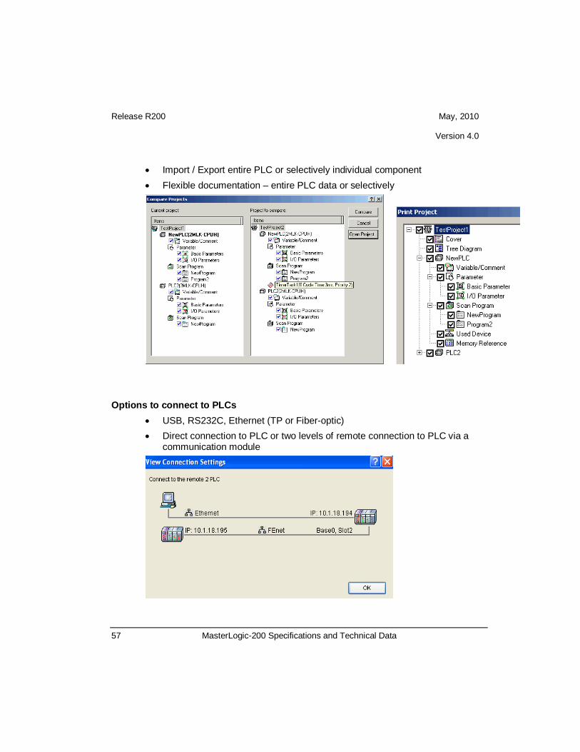
• Import / Export entire PLC or selectively individual component • Flexible documentation – entire PLC data or selectively
Options to connect to PLCs
• USB, RS232C, Ethernet (TP or Fiber-optic) • Direct connection to PLC or two levels of remote connection to PLC via a
communication module

Release R200 May, 2010 Version 4.0
58 MasterLogic-200 Specifications and Technical Data
User defined function blocks SoftMaster in association with MasterLogic-200 CPU allows the creation of password protected user defined function blocks. A user can build the custom logic & strategies in these function blocks using configurable input and output parameters & data types. These user defined function blocks can be password protected for security and copyright purposes
User defined data types SoftMaster allows the creation of user defined data types in addition to the standard IEC data types.
Monitoring When SoftMaster is in connected mode, it allows monitoring of the below functions: 1. Program Monitoring 2. Variable Monitoring 3. System Monitoring 4. Address Monitoring 5. Special Module Monitoring 6. Trend Monitoring 7. Data Traces
Debugging SoftMaster allows program debugging with advanced features like Step Over, Step Into, Step Out and Conditional Breakpoints.
Online SoftMaster provides the following features when it is connected with PLC: 1. Online Editing 2. Write programs to PLC 3. Read programs from PLC 4. Change Operation Mode (RUN/STOP/DEBUG) 5. Reset / Clear PLC

Release R200 May, 2010 Version 4.0
59 MasterLogic-200 Specifications and Technical Data
6. View PLC information / history / errors and warnings 7. Specify Flash Memory Setting 8. Forced I/O / Skip I/O Setting 9. Fault Mask Setting 10. Online Module Replacement
Simulation Simulation allows an engineer to programs without PLC, or debug program by using input condition setting or module simulation function. The following features are supported by the simulation environment: 1. Program simulation
The program written in LD/SFC/ST can be simulated. Online editing and debugging is supported by the simulation environment.
2. PLC online function
The program monitoring and online diagnostic functions (e.g. system monitoring / device monitoring) can be used during simulation.
3. Module simulation
Digital I/O module, A/D conversion module, D/A conversion module, High counter, Temperature control module can be simulated.
4. I/O input condition setting
Simulation environment supports setting device value or channel value of the I/O module as an input condition.

Release R200 May, 2010 Version 4.0
60 MasterLogic-200 Specifications and Technical Data
System Requirements
System Configuration Minimum
Processor 2.0 GHz Pentium IV or faster
RAM 128 MB
Video Resolution
1024 x 768
Hard Drive 10 GB
Operating System Windows XP/SP2, Windows Vista
External Interface RS232 Serial or USB

Release R200 May, 2010 Version 4.0
61 MasterLogic-200 Specifications and Technical Data
4. Model Numbers 4.1 CPU modules
Product Model Description Remarks
CPU Module
2MLI-CPUU High speed CPU module (Fully Non-redundant system) (Max. I/O point: 6,144 points)
2MLR-CPUH/T High speed CPU module (Fully Redundant system), Master, TP/CAT5 (Max. I/O point: 23,808 points)
2MLR-CPUH/F High speed CPU module (Fully Redundant system), Master, Fiber Optic (Max. I/O point: 23,808 points)
4.2 I/O base, cables (2MLI-CPUU)
Product Model Description Remarks
Main CPU Base (only for 2MLI-CPUU)
2MLB-M04A For 4 module installation
2MLB-M06A For 6 module installation
2MLB-M08A For 8 module installation
2MLB-M12A For 12 module installation
Expansion I/O Base (only for 2MLI-CPUU)
2MLB-E04A For 4 module installation
2MLB-E06A For 6 module installation
2MLB-E08A For 8 module installation
2MLB-E12A For 12 module installation

Release R200 May, 2010 Version 4.0
62 MasterLogic-200 Specifications and Technical Data
Product Model Description Remarks
Power module (only for 2MLI-CPUU)
2MLP-ACF1 AC 100V~240V input, DC 5V: 3A, DC 24V: 0.6A
2MLP-ACF2 AC 100V~240V input DC 5V: 6A
2MLP-AC23 AC 100V~240V input DC 5V: 8.5A
2MLP-DC42 DC 24V Input DC 5V: 6A
Expansion I/O cable (only for 2MLI-CPUU)
2MLC-E041 Length: 0.4m
Total extension distance should not exceed 15m
2MLC-E061 Length: 0.6m 2MLC-E121 Length: 1.2m 2MLC-E301 Length: 3.0m 2MLC-E501 Length: 5.0m 2MLC-E102 Length: 10.0m 2MLC-E152 Length: 15.0 m
4.3 I/O base, I/O interface modules, cables (2MLR-CPUH)
Product Model Description Remarks
Main CPU Base (for 2MLR-CPUH/T, 2MLR-CPUH/F)
2MLR-M06P CPU base for 6 module installation

Release R200 May, 2010 Version 4.0
63 MasterLogic-200 Specifications and Technical Data
Product Model Description Remarks
Expansion I/O Base (for 2MLR-CPUH/T, 2MLR-CPUH/F)
2MLR-E12P I/O Base for 12 module installation
Power module (for 2MLR-CPUH/T, 2MLR-CPUH/F)
2MLR-AC13 Power Module, 8.5A, Voltage (AC110V)
2MLR-AC23 Power Module, 8.5A, Voltage (AC220V)
2MLR-AC12 Power Module, 5.5A, Voltage (AC110V)
2MLR-AC22 Power Module, 5.5A, Voltage (AC220V)
2MLR-DC42 Power Module, 7.5A, Voltage (DC24V)
I/O interface modules (for 2MLR-CPUH/T, 2MLR-CPUH/F)
2MLR-DBSF I/O Interface Module, Fiber Optic
2MLR-DBST I/O Interface Module, TP/CAT5
2MLR-DBSH I/O Interface Module, Hybrid (Fiber Optic & TP/CAT5)
4.4 Digital I/O modules
Product Model Description Remarks
Digital Input Module
2MLI-D21A DC 24V Input, 8 point (Current source / sink input)
2MLI-D22A DC 24V Input, 16 point (Current source / sink input)
2MLI-D24A DC 24V Input, 32 point (Current source / sink input)

Release R200 May, 2010 Version 4.0
64 MasterLogic-200 Specifications and Technical Data
Product Model Description Remarks
2MLI-D28A DC 24V Input, 64 point (Current source / sink input)
2MLI-D22B DC 24V Input, 16 point (Current source input)
2MLI-D24B DC 24V Input, 32 point (Current source input)
2MLI-D28B DC 24V Input, 64 point (Current source input)
2MLI-A12A AC 110V input, 16 point 2MLI-A21A AC 220V input, 8 point
Digital Output Module
2MLQ-RY1A Relay output, 8 point (for 2A, single COM.)
2MLQ-RY2A Relay output, 16 point (for 2A)
2MLQ-RY2B Relay output, 16 point (for 2A), Varistor included
2MLQ-TR2A Transistor output, 16 point (for 0.5A, Sink output)
2MLQ-TR4A Transistor output, 32 point (for 0.1A, Sink output)
2MLQ-TR8A Transistor output, 64 point (for 0.1A, Sink output)
2MLQ-TR2B Transistor output 16 point (for 0.5A, Source output)
2MLQ-TR4B Transistor output 32 point (for 0.1A, Source output)
2MLQ-TR8B Transistor output 64 point (for 0.1A, Source output)
2MLQ-SS2A Triac output, 16 point (for 0.6A)

Release R200 May, 2010 Version 4.0
65 MasterLogic-200 Specifications and Technical Data
4.5 Analog I/O, HSC Modules
Product Model Description Remarks
Analog Input modules
2MLF-AV8A • Voltage Input: 8 channels • DC 1 ~ 5V / 0 ~ 5V / 0 ~ 10V / −10 ~ +10V
2MLF-AC8A • Current Input: 8 channels • DC 4 ~ 20mA / 0 ~ 20mA
2MLF-AD8A • Voltage/Current Input: 8 channels
2MLF-AD16A • Voltage/Current Input: 16 Channels
2MLF-AD4S • Voltage/Current Input: 4 channels • Isolation between channels
Analog Output modules
2MLF-DV4A • Voltage Output: 4 channels • DC 1 ~ 5V / 0 ~ 5V / 0 ~ 10V / −10 ~ +10V
2MLF-DC4A • Current Output: 4 channels • DC 4 ~ 20mA / 0 ~ 20mA
2MLF-DC4S Current Output: 4 channels, Isolation between channels
2MLF-DV8A • Voltage Output: 8 channels • DC 1 ~ 5V / 0 ~ 5V / 0 ~ 10V / −10 ~ +10V
2MLF-DC8A • Current Output:: 8 channels • DC 4 ~ 20mA / 0 ~ 20mA
Thermocouple Input Module
2MLF-TC4S Temperature (T/C) Input, 4 channels, Isolation between channels
RTD Input Module 2MLF-RD4A Temperature (RTD) Input, 4 channels
High speed Counter Module
2MLF-HO2A • Voltage Input type (Open Collector type) • 200 kHz, 2 channel
2MLF-HD2A • Differential Input type (Line Driver type) • 500 kHz, 2 channel

Release R200 May, 2010 Version 4.0
66 MasterLogic-200 Specifications and Technical Data
4.6 Communication Modules
Product Model Description Remarks
FEnet Module (Optical/ Electrical)
2MLL-EFMF • Fast Ethernet (multi-mode fiber-optic
media), Master • 100/10Mbps support
2MLL-EFMT • Fast Ethernet (CAT 5 media), Master • 100/10Mbps support
Snet Module
2MLL-C22A • Serial communication • RS-232C, 2 channels
2MLL-C42A • Serial communication • RS-422 (485), 2 channels
2MLL-CH2A • Serial communication • RS-232C 1 Channel / RS-422 (485) 1
Channel
Profibus-DP Module 2MLL-PMEA Profibus-DP Master Module
4.7 Programming Cables
Product Model Description Remarks
USB cable USB-301A Programming cable for USB port
4.8 Software Enviornment
Product Model Description Remarks

Release R200 May, 2010 Version 4.0
67 MasterLogic-200 Specifications and Technical Data
SoftMaster SSS-MLPT Programming tool for MasterLogic PLC
Experion PKS Interface Driver (Not required for Experion HS / LS)
SSS-MLDP Driver for integration with Experion PKS
4.9 Others
Product Model Description Remarks
Terminator 2MLT-TERA Must use for base expansion
Dummy module 2MLT-DMMA Dust protection module for unused slot

Release R200 May, 2010 Version 4.0
68 MasterLogic-200 Specifications and Technical Data
For More Information Learn more about Honeywell’s products/solutions visit our website www.honeywell.com/ps or contact your Honeywell account manager. Automation & Control Solutions Process Solutions Honeywell 2500 W. Union Hills Dr. Phoenix, AZ 85027 Tel: 877.466.3993 or 602.313.6665
00-00-000 May 2010 © 2010 Honeywell International Inc.
Experion, PlantScape, TotalPlant are U.S. registered trademarks of Honeywell International Inc. All other
products and brand names shown are trademarks of their respective owners.
While this information is presented in good faith and believed to be accurate, Honeywell disclaims the
implied warranties of merchantability and fitness for a particular purpose and makes no express warranties
except as may be stated in its written agreement with and for its customer. In no event is Honeywell liable
to anyone for any indirect, special or consequential damages. The information and specifications in this
document are subject to change without notice