mass flow meters for gases · datasheet t12 mass flow meters for gases measurement / control system...
TRANSCRIPT
Datasheet T12 Mass Flow Meters for Gases
Measurement / control system
Accuracy (incl. linearity) : ± 1% Rd plus ± 1% FS
(based on actual calibration)
Repeatability : < 0,2% FS typical
Turndown : 1 : 50 or 1 : 100 (see flow range table)
Operating pressure : 0…10 bar(g)
Pressure sensitivity : 0,3% Rd/bar typical at Air
Operating temperature : 0…50 oC
Temperature sensitivity : zero: < ± 0,1% FS/°C;
span: < ± 0,2% Rd/°C
Leak integrity (outboard) : < 2 x 10⁻⁹ mbar l/s He
Attitude sensitivity : max. error at 90° off horizontal 0,2%
at 1 bar, typical N2
Response time (sensor t63%) : 0,9 sec
Warm-up time : 30 min. for optimum accuracy
2 min. for accuracy ± 2% FS
Mechanical parts
Material (wetted parts) : SS316; other on request
Process connections : standard: none;
options: compression type or face seal male
Seals : standard: Viton®;
options: EPDM, FFKM (Kalrez®)
Ingress protection (housing) : IP65
Although all specifications in this datasheet are believed to be accurate, the right is
reserved to make changes without notice or obligation.
> Technical specifications
Model minimum maximum
T12 0,1…5 ln/min 0,5…50 ln/min
Intermediate ranges are available
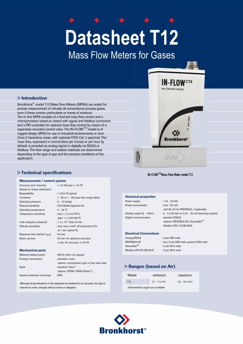
> Introduction
Bronkhorst® model T12 Mass Flow Meters (MFMs) are suited for precise measurement of virtually all conventional process gases, even if these contain particulates or traces of moisture. The in-line MFM consists of a thermal mass flow sensor and a microprocessor based pc-board with signal and fieldbus conversion and a PID controller for optional mass flow control by means of a separately mounted control valve. The IN-FLOWCTA model is of rugged design (IP65) for use in industrial environments or even Zone 2 hazardous areas, with optional ATEX Cat. 3 approval. The mass flow, expressed in normal liters per minute or per hour by default, is provided as analog signal or digitally via RS232 or fieldbus. The flow range and wetted materials are determined depending of the type of gas and the process conditions of the application.
> Ranges (based on Air)
Electrical properties
Power supply : +15…24 Vdc
Power consumption : max. 125 mA;
add 50 mA for PROFIBUS, if applicable
Analog output (0…100%) : 0…5 (10) Vdc or 0 (4)…20 mA (sourcing output)
Digital communication : standard RS232;
options: PROFIBUS DP, DeviceNetTM,
Modbus-RTU, FLOW-BUS
Electrical Connections
Analog/RS232 : 8-pin DIN male
PROFIBUS DP : bus: 5-pin DIN male; power:8-DIN male
DeviceNetTM : 5-pin M12 male
Modbus-RTU/FLOW-BUS : 5-pin M12 male
IN-FLOWCTA
Mass Flow Meter model T12

> Model number identification
> Thermal mass flow measuring principle IN-FLOWCTA Mass Flow Meters with inline sensor (no by-pass) consist of a straight flow channel, into which two stainless steel probes protrude; a heater probe and a temperature sensor probe. A constant temperature (ΔT) is created between the two probes and the energy required to maintain this ΔT is proportional to the mass flow rate. Based on this concept, mass flow can be measured with low pressure drop, mainly caused by the gas fittings and the mesh screens which are incorporated for flow conditioning (see figure below). Compared to traditional thermal MFMs and MFCs with by-pass, the construction of the direct measuring CTA principle (Constant Temperature Anemometry) is less sensitive to humidity and contamination. Functional scheme of the thermal mass flow sensor
Base 1 Meter
Communication (I/O) A RS232 + analog (n/c control) B RS232 + analog (n/o control) D RS232 + DeviceNet (n/c) E RS232 + DeviceNet (n/o) M RS232 + Modbus-RTU (n/c) N RS232 + Modbus-RTU (n/o) P RS232 + Profibus-DP (n/c) Q RS232 + Profibus-DP (n/o) R RS232 + FLOW-BUS (n/c)
S RS232 + FLOW-BUS (n/o)
T
Capacity (based on air) 2 low flow (LF) up to 50 ln/min
Internal seals V Viton® (factory standard) E EPDM
K Kalrez® (FFKM)
Connections (in/out) 0 None (factory standard) 2 ¼” OD compression type 3 6 mm OD compression type 4 12 mm OD compression type 5 ½” OD compression type
8 ¼” Face seal male
Supply voltage D + 15…24 Vdc
> State of the art digital design Todays IN-FLOWCTA series are equipped with a digital pc-board, offering high accuracy, excellent temperature stability and fast response. The basic digital pc-board contains all of the general functions needed for measurement and control. In addition to the standard RS232 output the instruments also offer analog I/O. Furthermore, an integrated interface board provides DeviceNetTM, PROFIBUS DP, Modbus-RTU or FLOW-BUS protocols.
Functional scheme of the digital PC-board
1 2 A
Analog output A 0…5 Vdc B 0…10 Vdc F 0…20 mA sourcing
G 4…20 mA sourcing
Pheater = Poffset + C.Ømn
Pheater = total heater power Poffset = heater power offset at zero flow C = constant Øm = mass flow n = dimensionless factor
N N N NN
The special mess screens make the instruments less sensitive to changes
of the inlet piping conditions

> Hook-up diagram for analog or RS232 communication
> Hook-up diagrams for fieldbus communication For the available fieldbus options we refer to the various hook-up diagrams as indicated below. If you are viewing this datasheet in digital format, you may use the hyperlink to each of the drawings. Otherwise please visit the download section on www.bronkhorst.com or contact our local representatives.
Doc. 9.16.054 Doc. 9.16.053
Doc. 9.16.052
Doc. 9.16.054
Doc. 9.16.051
Doc. 9.16.053
Doc. 9.16.065
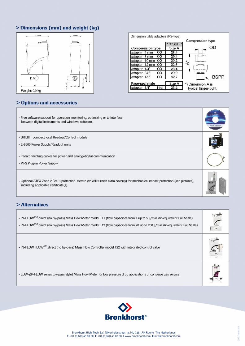
> Dimensions (mm) and weight (kg)
E.D
S.T
12.0
213.B
Dimension table adapters (RS-type)
> Options and accessories
- Free software support for operation, monitoring, optimizing or to interface between digital instruments and windows software.
- BRIGHT compact local Readout/Control module
- E-8000 Power Supply/Readout units
- Interconnecting cables for power and analog/digital communication
- PiPS Plug-in Power Supply
- Optional ATEX Zone 2 Cat. 3 protection. Hereto we will furnish extra cover(s) for mechanical impact protection (see pictures), including applicable certificate(s).
> Alternatives
- IN-FLOWCTA direct (no by-pass) Mass Flow Meter model T11 (flow capacities from 1 up to 5 ln/min Air-equivalent Full Scale)
- IN-FLOWCTA direct (no by-pass) Mass Flow Meter model T13 (flow capacities from 20 up to 200 ln/min Air-equivalent Full Scale)
- IN-FLOW FLOWCTA direct (no by-pass) Mass Flow Controller model T22 with integrated control valve
- LOW-∆P-FLOW series (by-pass style) Mass Flow Meter for low pressure drop applications or corrosive gas service
Weight: 0,9 kg
Bronkhorst High-Tech B.V. Nijverheidsstraat 1a, NL-7261 AK Ruurlo The Netherlands
T +31 (0)573 45 88 00 F +31 (0)573 45 88 08 I www.bronkhorst.com E [email protected]