marvac catalogue
DESCRIPTION
dTRANSCRIPT
Tank
Protection
Products

The effects of exceeding design pressure or vacuum limitsin unprotected storage tanks and facilities, can havecatastrophic effects on both plant and personnel.
Pressure/Vacuum valves should be used to protect anypressurised system from the effects of exceeding its designpressure limit.
A Pressure/Vacuum valve is designed to breathe out duringtank filling and breathe in while the tank is being emptied.
Liquid storage tanks containing harmful or dangerousvapours can be protected by the use of inert gas blankets.These blankets are controlled by self regulating tankblanketing valves.
Many tank systems require access for cleaning and forsampling, for this Manways and Gauge Hatches arerequired.
Marvac design and manufacture valves to ISO9001 indifferent configurations to suit a variety of applications.These valves are compliant with the European ATEX andPED directives when applicable.
The Marvac range of tank equipment comprises:
• Low Pressure Safety Valves
• Low Pressure Pilot Valves
• Vacuum Valves
• Combination Pressure/Vacuum Valves
• Emergency Vent/Manways
• Gauge Hatches
• Tank Blanketing Valves
All Marvac valves are available through ourglobal agent distribution network,supported by our own regional salesoffices around the world.
I n t r o d u c t i o n
CO
NT
EN
TS
2
S E C T I O N PAG E C O N T E N T S
Introduction 3 - 6 Introduction
7 - 10 How they work
11 - 18 Dimensions and weights
18 - 19 Accessories
20 Materials
Sizing 21 - 23 Determination of venting requirement - API 2000
24 Surface area calculation
25 Gas flow conversion
26 Tank blanketing valve sizing
27 API 2000 Formula
28 Coefficients
29 Useful vapour and gas data
Capacity 30 - 33 Air capacity tables
Terms, Definitions 34 Useful terms and definitionsand Conversions
35 Useful conversions
Transportation Protection 36 ‘Megaflo’ P/V Valve
36 ‘Tank-A-Vent’ Bursting Disc

IN
TR
OD
UC
TIO
N
3
Marvac manufacture an extensive range ofproducts to protect low pressure storage tanksand vessels.These products help to preventdamage to the tank and also prevent the tankscontents from escaping, ensuring the safety ofpersonnel and the surrounding environment.
Pressure/Vacuum valves are designed to limit the maximumpressure and vacuum that can exist in a tank.When a tankis being filled the gas (air, vapour, etc.) that filled the spaceabove the liquid is compressed and if this pressure was allowedto exceed the design pressure of the tank, then it would explode. Also, if the temperatureof the tank increases, then the effect of vaporisation and expansion would cause the pressure to rise. Conversely,emptying the tank, or a reduction in temperature, causes a vacuum to be created.
If the stored liquid is not volatile then the tank can be allowed to breathe through a free vent (fig 750).This iseffectively an orifice with a hood and screen to keep out rain and birds. However, if the liquid is volatile then a freevent will allow valuable product vapour to be emitted to the atmosphere.
Fitting a relief valve allows the pressure in the tank to be increased above atmospheric. Such an increase inpressure, increases the boiling point of the liquid, reducing the amount of vapour which would otherwise form.When the relief valve does lift it will predominantly discharge air rather than product vapour.
Pressure/Vacuum Relief ValvesThe Marvac range of pressure only, vacuum only and combined pressure and vacuum relief valves, can be weight,spring or pilot operated. These valves are extensively used to alleviate the problems caused by thermal effects andthe filling and emptying of storage tanks and vessels.
I N T R O D U C I N G T H E
M A R VA C R A N G E O F
TA N K P R O T E C T I O N
VA LV E S
VACUUM RELIEF RANGE (Typical diagrams)
PRESSURE RELIEF ATMOSPHERIC VENT RANGE (Typical diagrams)
Weight loaded
Weight loaded Pilot operated
Spring loaded Side mounted(Weight or Spring loaded)
Spring loaded
IN
TR
OD
UC
TIO
N
4
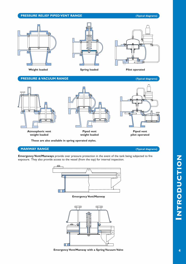
PRESSURE RELIEF PIPED VENT RANGE (Typical diagrams)
PRESSURE & VACUUM RANGE (Typical diagrams)
MANWAY RANGE (Typical diagrams)
Emergency Vent/Manways provide over pressure protection in the event of the tank being subjected to fireexposure. They also provide access to the vessel (from the top) for internal inspection.
Weight loaded
Atmospheric ventweight loaded
Piped ventweight loaded
Piped ventpilot operated
Spring loaded Pilot operated
These are also available in spring operated styles.
Emergency Vent/Manway
Emergency Vent/Manway with a Spring Vacuum Valve

IN
TR
OD
UC
TIO
N
5
GAUGE HATCH RANGE (Typical diagrams)
TRANSPORTATION VALVE (Typical diagram)
TANK BLANKETING RANGE (Typical diagram) FREE VENT (Typical diagram)
A Pressure/Vacuum orPressure only safetyrelief valve, to meet thestringent requirementsdemanded by the Road,Rail and Container Tankindustry.
Gauge Hatches allow access for productlevel measurement and sampling.
Foot operated
Lockable
Tank Blanketing Valves-Dedicated to provideinert or rich blanketingof storage tanks toreduce harmful fugitiveemissions and theevaporation of product.

IN
TR
OD
UC
TIO
N
6
* To avoid tank corrosion or stored fluid degradation due to the ingress of air (humidity).* To reduce the risk of explosion by diluting the oxygen in the tank with inert gas.* To protect the environment from gases being emitted directly to the atmosphere.* To protect the tank from imploding due to extreme vacuum conditions.
TANK BLANKETING SYSTEMS FIGURE 77A
PRODUCT CODING
GAS BLANKET SUPPLY LINE
GAS BLANKET2mbarg to 1000mbarg
STORED LIQUID
SENSELINE
TANK BLANKETINGSYSTEM
PRESSURE / VACUUMRELIEF VALVE
1.4 barg to 14 barg
TYPICAL EXAMPLETank blanketing valve, size 1", stainless steel body,ANSI 300 connection, 75% excess flow, viton gaskets, supply filter.
77A H X 2 4 V A F
TANKBLANKETINGVALVE
BODY SIZEF = 1/2"H = 1"J = 2"
CONNECTION RATING1 = 150#RF or PN 162 = 300#RF or PN 409 = THREADED
SEAT AND SEAL MATERIALV = VITON (Standard)B = BUNA-NC = CHEMRAZE = EPDMK = KALREZ(gasket over diaphragm is always PTFE)
CONNECTION STANDARD A = ANSIP = PNN = NPT
ACCESSORIESA = NONEF = SUPPLY FILTERP = INTEGRAL PRESSURE SENSINGI = BACK FLOW PREVENTOR
FLOW RESTRICTIONRestriction as a % of maximum flow
Valve SizeCode 0.5" 1.0" 2.0"
1 N/A 10% 20%2 N/A 25% 40%3 N/A 50% 60%4 N/A 75% 80%0 100% 100% 100%
MATERIALC = CARBON STEELX = 316 St. St.

HO
WT
HE
YW
OR
K
7
VACUUM RELIEF
PRESSURE RELIEF
COMBINED PRESSURE & VACUUM RELIEF
The operation of the Vacuum relief pallet and the Pressure relief are as explained above.
Fig.1 Valve closed.The downward acting force “A” (generated fromeither weights or a spring) provides the vacuum setpressure.This force is greater than the atmosphericforce “B” acting upward.When the tank is filling, force“C” is generated, which acts with force “A” keepingthe valve firmly closed.
Fig. 2 Valve open.When the tank is emptying, a vacuum force “C” isgenerated, which helps to lift the pallet by acting withforce “B” and against force “A”.This allows the tankto breathe air in.
Fig. 3 Valve closed.The downward acting force “A” (generated fromeither weights or a spring) provides the set pressure.This force is greater than the system operating force“B” acting upward.
Fig. 4 Valve open.When the system pressure force “B” increases toabove force “A”, the pallet lifts and the tank vapoursare released to the atmosphere. If such vapours arenot permitted to be vented to atmosphere, a pipedvent version is available.
Fig. 5 Tank emptying. Fig. 6 Tank filling.
Weight orSpring loaded
Pallet
Weight orSpring loaded
Pallet
VacuumRelief Pallet
PressureRelief Pallet

HO
WT
HE
YW
OR
K
8
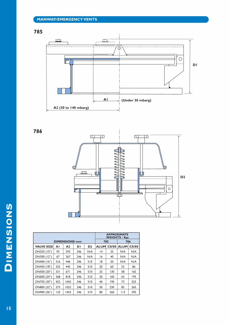
MANWAY/EMERGENCY VENTS
GAUGE HATCHES
Gauge hatches allow access forproduct level measurement andsampling.
There are two types:
Foot operated: where quickaccess is required.To be used onnon-pressure containing systems.
Lockable: for use on systems thatare subject to pressurisation.Thecover is held in place by the swingbolt, which has a hand wheel foreasy locking.
Manway/Emergency Vents
These items have two uses:The pallet is hinged and can be manually lifted out ofthe way allowing access to the tank for cleaning andinspection.
Secondly the pallet has weights which can becalculated to give a defined set pressure. In the eventof a fire the pallet will lift at a predeterminedpressure, thus supplying a large venting area.
By positioning the weights at different distances fromthe pivot point a wide variation in set pressures canbe achieved.
Manway/Emergency Vents
These items can also be supplied withvacuum valves.
High Set Pressures
Medium Set Pressures
Low Set Pressures
Weight
Weight
Weight
Pivot
HO
WT
HE
YW
OR
K
9
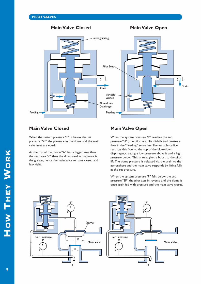
PILOT VALVES
Main Valve Closed
When the system pressure “P” is below the setpressure “SP”, the pressure in the dome and the mainvalve inlet are equal.
As the top of the piston “A” has a bigger area thanthe seat area “a”, then the downward acting force isthe greater, hence the main valve remains closed andleak tight.
Main Valve Open
When the system pressure “P” reaches the setpressure “SP”, the pilot seat lifts slightly and creates aflow in the “Feeding” sense line.The variable orificerestricts this flow to the top of the blow-downdiaphragm, creating a low pressure above it and a highpressure below. This in turn gives a boost to the pilotlift.The dome pressure is released via the drain to theatmosphere and the main valve responds by lifting fullyat the set pressure.
When the system pressure “P” falls below the setpressure “SP” the pilot acts in reverse and the dome isonce again fed with pressure and the main valve closes.
Main Valve Closed Main Valve Open
HO
WT
HE
YW
OR
K
10
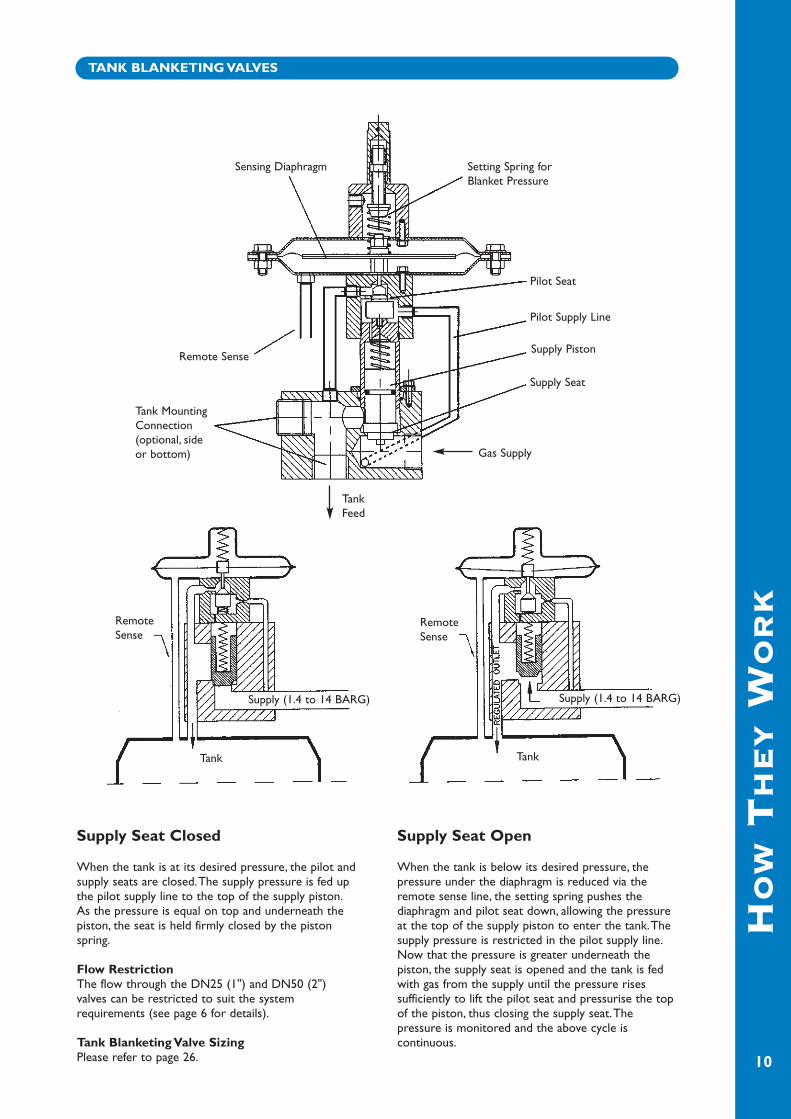
TANK BLANKETING VALVES
Supply Seat Closed
When the tank is at its desired pressure, the pilot andsupply seats are closed.The supply pressure is fed upthe pilot supply line to the top of the supply piston.As the pressure is equal on top and underneath thepiston, the seat is held firmly closed by the pistonspring.
Flow RestrictionThe flow through the DN25 (1") and DN50 (2")valves can be restricted to suit the systemrequirements (see page 6 for details).
Tank Blanketing Valve SizingPlease refer to page 26.
Supply Seat Open
When the tank is below its desired pressure, thepressure under the diaphragm is reduced via theremote sense line, the setting spring pushes thediaphragm and pilot seat down, allowing the pressureat the top of the supply piston to enter the tank.Thesupply pressure is restricted in the pilot supply line.Now that the pressure is greater underneath thepiston, the supply seat is opened and the tank is fedwith gas from the supply until the pressure risessufficiently to lift the pilot seat and pressurise the topof the piston, thus closing the supply seat.Thepressure is monitored and the above cycle iscontinuous.
Sensing Diaphragm
Remote Sense
TankFeed
Tank MountingConnection(optional, sideor bottom)
Tank Tank
Setting Spring forBlanket Pressure
Pilot Seat
Pilot Supply Line
Supply Piston
Supply Seat
Gas Supply
Supply (1.4 to 14 BARG)Supply (1.4 to 14 BARG)
RemoteSense
RemoteSense
DIM
EN
SIO
NS
11
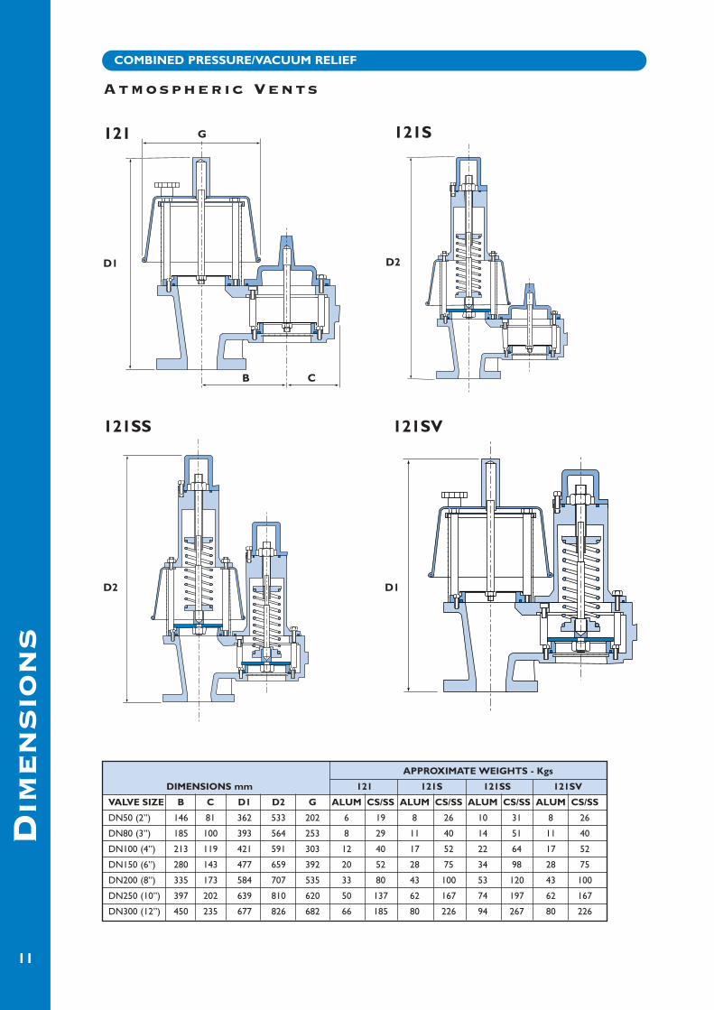
APPROXIMATE WEIGHTS - Kgs
DIMENSIONS mm 121 121S 121SS 121SV
VALVE SIZE B C D1 D2 G ALUM CS/SS ALUM CS/SS ALUM CS/SS ALUM CS/SS
DN50 (2”) 146 81 362 533 202 6 19 8 26 10 31 8 26
DN80 (3”) 185 100 393 564 253 8 29 11 40 14 51 11 40
DN100 (4”) 213 119 421 591 303 12 40 17 52 22 64 17 52
DN150 (6”) 280 143 477 659 392 20 52 28 75 34 98 28 75
DN200 (8”) 335 173 584 707 535 33 80 43 100 53 120 43 100
DN250 (10”) 397 202 639 810 620 50 137 62 167 74 197 62 167
DN300 (12”) 450 235 677 826 682 66 185 80 226 94 267 80 226
Atmospheric Vents
COMBINED PRESSURE/VACUUM RELIEF
121
121SS 121SV
121S
D1 D2
D2 D1
B C
G

APPROXIMATE WEIGHTS - Kgs
DIMENSIONS mm 121F 121FS 121FSS 121FSV
VALVE SIZE B C D1 D2 E F ALUM CS/SS ALUM CS/SS ALUM CS/SS ALUM CS/SS
DN50 (2”) 146 81 364 528 197 140 9 41 11 48 13 55 11 48
DN80 (3”) 185 100 424 571 238 180 12 60 16 70 20 80 16 70
DN100 (4”) 213 119 472 612 261 200 18 85 25 97 32 109 25 97
DN150 (6”) 280 143 517 670 310 242 32 113 40 125 48 137 40 125
DN200 (8”) 335 173 590 730 362 310 50 168 60 188 70 208 60 188
DN250 (10”) 397 202 650 831 400 358 76 250 88 280 100 310 88 280
DN300 (12”) 450 235 725 870 435 393 101 346 115 385 130 424 115 385
DIM
EN
SIO
NS
12
COMBINED PRESSURE/VACUUM RELIEF
Piped Vents
121F
121FSS 121FSV
121FS
D1 D2
D2 D1
B
E
F C
DIM
EN
SIO
NS
13
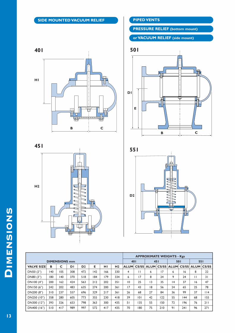
APPROXIMATE WEIGHTS - Kgs
DIMENSIONS mm 401 451 501 551
VALVE SIZE B C D1 D2 E H1 H2 ALUM CS/SS ALUM CS/SS ALUM CS/SS ALUM CS/SS
DN50 (2”) 140 105 308 472 142 166 330 4 11 6 17 6 16 8 22
DN80 (3”) 180 140 370 518 184 179 334 6 17 8 24 9 24 11 31
DN100 (4”) 200 162 424 563 212 202 351 10 25 13 35 14 37 16 47
DN150 (6”) 242 202 483 635 274 200 361 17 43 18 56 24 65 25 78
DN200 (8”) 310 237 557 696 329 217 361 26 68 27 84 36 99 37 114
DN250 (10”) 358 280 605 773 355 230 418 39 101 42 122 55 144 68 155
DN300 (12”) 393 326 653 798 363 300 435 51 135 55 150 72 196 76 211
DN400 (16”) 510 417 989 997 572 417 435 70 180 75 210 91 241 96 271
SIDE MOUNTED VACUUM RELIEF PIPED VENTS
PRESSURE RELIEF (bottom mount)
or VACUUM RELIEF (side mount)
401
451551
501
H1
D1
H2
D2
BB
E
CC
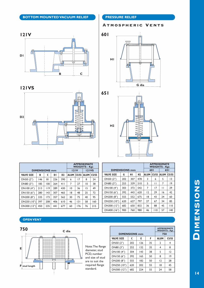
APPROXIMATEWEIGHTS - Kgs
DIMENSIONS mm 121V 121VS
VALVE SIZE B C D1 D2 ALUM CS/SS ALUM CS/SS
DN50 (2”) 146 81 226 390 6 17 8 24
DN80 (3”) 185 100 264 411 7 27 10 38
DN100 (4”) 213 119 289 430 10 36 15 49
DN150 (6”) 280 143 307 465 18 48 25 72
DN200 (8”) 335 173 357 562 30 75 40 95
DN250 (10”) 397 208 406 610 46 131 58 160
DN300 (12”) 450 235 441 677 60 176 76 215
APPROXIMATEWEIGHTS - Kgs
DIMENSIONS mm 601 651
VALVE SIZE G H1 H2 ALUM CS/SS ALUM CS/SS
DN50 (2”) 202 307 478 3 6 5 13
DN80 (3”) 253 339 510 5 11 7 19
DN100 (4”) 303 372 542 7 17 11 29
DN150 (6”) 392 443 620 12 29 16 42
DN200 (8”) 555 552 675 18 43 24 60
DN250 (10”) 620 627 797 27 67 34 85
DN300 (12”) 682 650 832 36 88 45 110
DN400 (16”) 900 760 980 46 110 57 140
APPROXIMATEWEIGHTS - Kgs
DIMENSIONS mm 750
VALVE SIZE C E F ALUM CS/SS
DN50 (2”) 202 126 35 2 4
DN80 (3”) 252 132 35 4 8
DN100 (4”) 304 143 38 5 12
DN150 (6”) 392 165 50 8 19
DN200 (8”) 555 182 50 12 28
DN250 (10”) 620 202 55 18 45
DN300 (12”) 682 224 55 24 58
DIM
EN
SIO
NS
14
BOTTOM MOUNTED VACUUM RELIEF PRESSURE RELIEF
Atmospheric Vents
OPEN VENT
121V
121VS651
750
601
D1H1
D2
H2
B C
G dia
E
F stud length
C dia
Note:The flangediameter, studPCD, numberand size of studare to suit therequired flangestandard.
DIM
EN
SIO
NS
15
APPROXIMATEWEIGHTS - Kgs
DIMENSIONS mm 785 786
VALVE SIZE A1 A2 D1 D2 ALUM CS/SS ALUM CS/SS
DN250 (10”) 93 293 246 N/A 14 35 N/A N/A
DN300 (12”) 67 367 246 N/A 16 40 N/A N/A
DN400 (16”) 316 446 246 510 18 50 N/A N/A
DN450 (18”) 325 445 246 510 20 60 53 86
DN500 (20”) 331 671 246 510 25 130 58 165
DN600 (24”) 368 818 246 510 30 160 63 195
DN750 (30”) 422 1042 246 510 40 190 73 225
DN800 (32”) 273 1022 246 510 50 230 83 265
DN900 (36”) 125 1455 246 510 80 260 113 295
MANWAY/EMERGENCY VENTS
785
786
D1
D2
A2 (30 to 140 mbarg)
(Under 30 mbarg)A1

APPROXIMATEWEIGHTS - Kgs
DIMENSIONS mm 920
VALVE SIZE A B C D1 D2 E ALUM CS/SS
2” x 3” 153 146 81 455 505 226 35 46
3” x 4” 193 185 100 527 580 252 50 70
4” x 6” 200 213 119 540 605 300 72 100
6” x 8” 245 280 143 585 655 340 100 140
8” x 10” 330 335 173 660 760 406 151 210
10” x 12” 410 397 202 780 885 456 254 354
12” x 16” 510 450 235 860 970 530 371 515
DIM
EN
SIO
NS
16
APPROXIMATEWEIGHTS - Kgs
DIMENSIONS mm 930
VALVE SIZE B C D1 D2 ALUM CS/SS
2” 100 275 376 416 7 20
3” 120 275 400 450 8 22
4” 150 305 420 485 10 27
6” 197 327 430 530 15 39
8” 250 366 488 588 23 58
10” 303 400 533 638 34 88
12” 361 491 665 775 42 105
APPROXIMATEWEIGHTS - Kgs
DIMENSIONS mm 910
VALVE SIZE A C D1 D2 E ALUM CS/SS
2” x 3” 153 275 305 355 76 15 26
3” x 4” 193 290 327 380 89 20 40
4” x 6” 200 308 318 385 118 32 50
6” x 8” 245 380 335 435 146 45 80
8” x 10” 330 410 365 465 171 71 130
10” x 12” 410 470 405 510 201 117 240
12” x 16” 510 500 472 580 242 186 330
PILOT OPERATED PRESSURE RELIEF - PIPED VENT
Diagram is a high pressure pilot valve (above 300mbarg).Low pressure pilot (below 300 mbarg) shown dotted.
Diagram is a high pressure pilot valve (above 300mbarg).Low pressure pilot (below 300 mbarg) shown dotted.
Diagram is a high pressure pilot valve (above 300mbarg).Low pressure pilot (below 300 mbarg) shown dotted.
PILOT OPERATED PRESSURE RELIEF - ATMOSPHERIC VENT
910
D1D2
C
E
A
920
D1
D2
CB
E
A
930
D1D2
CB
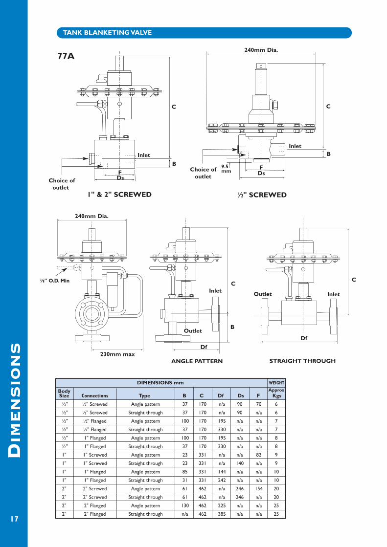
DIMENSIONS mm WEIGHT
BodySize Connections Type B C Df Ds F Kgs
1⁄2" 1⁄2" Screwed Angle pattern 37 170 n/a 90 70 61⁄2" 1⁄2" Screwed Straight through 37 170 n/a 90 n/a 61⁄2" 1⁄2" Flanged Angle pattern 100 170 195 n/a n/a 71⁄2" 1⁄2" Flanged Straight through 37 170 330 n/a n/a 71⁄2" 1" Flanged Angle pattern 100 170 195 n/a n/a 81⁄2" 1" Flanged Straight through 37 170 330 n/a n/a 8
1" 1" Screwed Angle pattern 23 331 n/a n/a 82 9
1" 1" Screwed Straight through 23 331 n/a 140 n/a 9
1" 1" Flanged Angle pattern 85 331 144 n/a n/a 10
1" 1" Flanged Straight through 31 331 242 n/a n/a 10
2" 2" Screwed Angle pattern 61 462 n/a 246 154 20
2" 2" Screwed Straight through 61 462 n/a 246 n/a 20
2" 2" Flanged Angle pattern 130 462 225 n/a n/a 25
2" 2" Flanged Straight through n/a 462 385 n/a n/a 25
DIM
EN
SIO
NS
17
TANK BLANKETING VALVE
77A
B
C
FDs
240mm Dia.
240mm Dia.
Choice ofoutlet
Choice ofoutlet
Inlet
1" & 2" SCREWED
B
9.5mm
C
C
FDs
Inlet
1⁄2" SCREWED
230mm max
3⁄8" O.D. Min
Df
Df
C
BOutlet
Outlet
ANGLE PATTERN STRAIGHT THROUGH
InletInlet
Approx
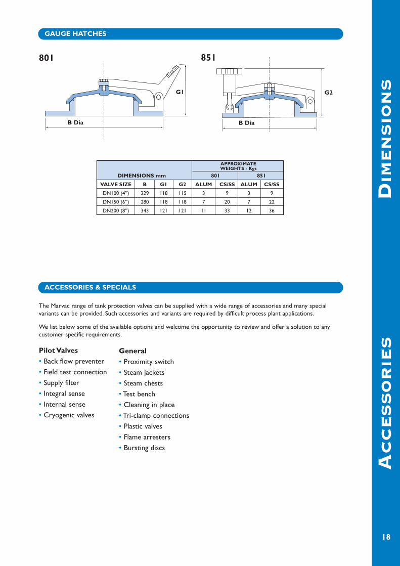
APPROXIMATEWEIGHTS - Kgs
DIMENSIONS mm 801 851
VALVE SIZE B G1 G2 ALUM CS/SS ALUM CS/SS
DN100 (4”) 229 118 115 3 9 3 9
DN150 (6”) 280 118 118 7 20 7 22
DN200 (8”) 343 121 121 11 33 12 36
DIM
EN
SIO
NS
AC
CE
SS
OR
IE
S
18
GAUGE HATCHES
ACCESSORIES & SPECIALS
801
G1
B Dia
851
G2
B Dia
The Marvac range of tank protection valves can be supplied with a wide range of accessories and many specialvariants can be provided. Such accessories and variants are required by difficult process plant applications.
We list below some of the available options and welcome the opportunity to review and offer a solution to anycustomer specific requirements.
Pilot Valves• Back flow preventer
• Field test connection
• Supply filter
• Integral sense
• Internal sense
• Cryogenic valves
General• Proximity switch
• Steam jackets
• Steam chests
• Test bench
• Cleaning in place
• Tri-clamp connections
• Plastic valves
• Flame arresters
• Bursting discs

AC
CE
SS
OR
IE
S
19
Flame Arrester
Steam Jacket
Tri-Clamp
Back Flow Preventer Field Test Connector
Supply Filter
Proximity Switch
Valve Range
121 ✓ ✓ ✓ ✓ ✓ X X X X ✓ ✓ ✓ ✓ ✓
401/451 ✓ ✓ ✓ ✓ ✓ X X X X ✓ ✓ ✓ ✓ ✓
501/551 ✓ ✓ ✓ ✓ ✓ X X X X ✓ ✓ ✓ ✓ ✓
601/651 ✓ ✓ ✓ ✓ ✓ X X X X ✓ ✓ ✓ ✓ ✓
750 ✓ ✓ X ✓ X X X X X n/a n/a X X X
785/786 X X X X X ✓ ✓ ✓ X ✓ ✓ X X ✓
910 ✓ ✓ ✓ ✓ ✓ X X X ✓ X ✓ X X ✓
920 ✓ ✓ ✓ ✓ ✓ X X X ✓ X ✓ X X ✓
930 ✓ ✓ ✓ ✓ ✓ X X X ✓ X ✓ X X ✓
801/851 ✓ ✓ X ✓ X X X X X X ✓ ✓ ✓ ✓
77A X ✓ X ✓ X X X X X X ✓ X X X
O11 X X X ✓ ✓ X X X X X ✓ X X X
MA
TE
RIA
LS
20
Alu
min
ium
Car
bon
stee
l
Low
Tem
p.C
S
Sta
inle
ss s
teel
Hig
h G
r.A
lloys
Fabr
icat
ed C
S
Fabr
icat
ed S
S
Fabr
icat
ed A
lum
Cry
ogen
ic
Met
al s
eat
So
ft s
eat
Poly
pro
pyle
ne
PV
DF
Hal
ar C
oat
ed
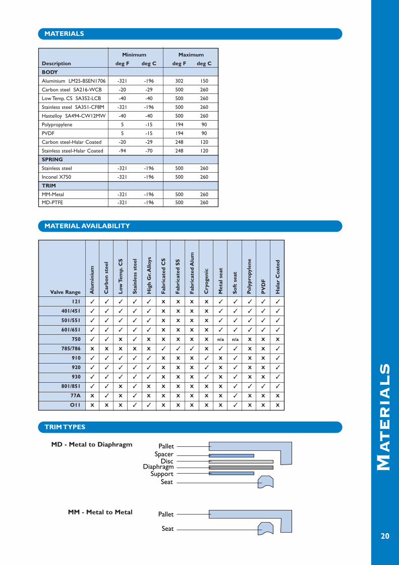
MD - Metal to Diaphragm
MM - Metal to Metal
MATERIALS
MATERIAL AVAILABILITY
TRIM TYPES
Minimum Maximum
Description deg F deg C deg F deg C
BODY
Aluminium LM25-BSEN1706 -321 -196 302 150
Carbon steel SA216-WCB -20 -29 500 260
Low Temp. CS SA352-LCB -40 -40 500 260
Stainless steel SA351-CF8M -321 -196 500 260
Hastelloy SA494-CW12MW -40 -40 500 260
Polypropylene 5 -15 194 90
PVDF 5 -15 194 90
Carbon steel-Halar Coated -20 -29 248 120
Stainless steel-Halar Coated -94 -70 248 120
SPRING
Stainless steel -321 -196 500 260
Inconel X750 -321 -196 500 260
TRIM
MM-Metal -321 -196 500 260
MD-PTFE -321 -196 500 260

IMPERIAL
Tank capacity (Physical) In-Breathing
Barrels US Gallons SCFH Air
60 2,500 60
100 4,200 100
500 21,000 500
1,000 42,000 1,000
2,000 84,000 2,000
3,000 126,000 3,000
4,000 168,000 4,000
5,000 210,000 5,000
10,000 420,000 10,000
15,000 630,000 15,000
20,000 840,000 20,000
25,000 1,050,000 24,000
30,000 1,260,000 28,000
35,000 1,470,000 31,000
40,000 1,680,000 34,000
45,000 1,890,000 37,000
50,000 2,100,000 40,000
60,000 2,520,000 44,000
70,000 2,940,000 48,000
80,000 3,360,000 52,000
90,000 3,780,000 56,000
100,000 4,200,000 60,000
120,000 5,040,000 68,000
140,000 5,880,000 75,000
160,000 6,720,000 82,000
180,000 7,560,000 90,000
SIZ
IN
G
21
METRIC
Tank capacity (Physical) In-Breathing
Cubic metres Litres Nm3/h Air
10 10,000 1.69
20 20,000 3.37
100 100,000 16.90
200 200,000 33.70
300 300,000 50.60
500 500,000 84.30
700 700,000 118
1,000 1,000,000 169
1,500 1,500,000 253
2,000 2,000,000 337
3,000 3,000,000 506
3,180 3,180,000 536
4,000 4,000,000 647
5,000 5,000,000 787
6,000 6,000,000 896
7,000 7,000,000 1,003
8,000 8,000,000 1,077
9,000 9,000,000 1,136
10,000 10,000,000 1,210
12,000 12,000,000 1,345
14,000 14,000,000 1,480
16,000 16,000,000 1,615
18,000 18,000,000 1,745
20,000 20,000,000 1,877
25,000 25,000,000 2,179
30,000 30,000,000 2,495
Determination of Equivalent Air Venting
Requirements to API 2000
The following scenarios should be considered when determining the venting requirements of atmospheric or low pressurestorage tanks.
1/ Tank In-Breathing - VACUUM RELIEF:The total requirement is the sum of the following two scenarios.A/ The resultant air flow in to the tank due to the out-flow of liquid during emptying.B/ Thermal in-breathing due to the atmospheric cooling effect (contracting or condensing) on the vapour within thetank.
2/ Tank Out-Breathing - PRESSURE RELIEF:The total requirement is the sum of the following three scenarios.A/ The resultant air flow out of the tank due to the in-flow of liquid during filling.B/ Thermal out-breathing due to the atmospheric heating effect (expansion) on the vapour within the tank.C/ The maximum flow from the tank blanketing valve, should it fail open.
3/ Out-Breathing due to External Fire - PRESSURE RELIEF
When a tank can be subjected to an external fire source, the venting requirement can exceed the requirements outlinedabove.
1/ Tank In-Breathing - VACUUM RELIEF:
A/ Liquid emptying:IMPERIAL - For each Barrel/hr (42 USGPH) of liquid being emptied, an in-breathing rate of 5.6 SCFH of air is required.METRIC - For each M3/h (1000 l/h) of liquid being emptied, an in-breathing rate of 0.94 Nm3/h of air is required.B/ Thermal contraction:Read the in-breathing rate from the tables below.It is important to realise that the Tank Capacity stated is the physical capacity (volume) and not the emptying rate.

SIZ
IN
G
22
IMPERIAL
Out-breathing
*Flash>=100°F *Flash<100°FTank capacity (Physical) Boiling>=300°F Boiling<300°F
Barrels US Gallons SCFH Air SCFH Air
60 2,500 40 60
100 4,200 60 100
500 21,000 300 500
1,000 42,000 600 1,000
2,000 84,000 1,200 2,000
3,000 126,000 1,800 3,000
4,000 168,000 2,400 4,000
5,000 210,000 3,000 5,000
10,000 420,000 6,000 10,000
15,000 630,000 9,000 15,000
20,000 840,000 12,000 20,000
25,000 1,050,000 15,000 24,000
30,000 1,260,000 17,000 28,000
35,000 1,470,000 19,000 31,000
40,000 1,680,000 21,000 34,000
45,000 1,890,000 23,000 37,000
50,000 2,100,000 24,000 40,000
60,000 2,520,000 27,000 44,000
70,000 2,940,000 29,000 48,000
80,000 3,360,000 31,000 52,000
90,000 3,780,000 34,000 56,000
100,000 4,200,000 36,000 60,000
120,000 5,040,000 41,000 68,000
140,000 5,880,000 45,000 75,000
160,000 6,720,000 50,000 82,000
180,000 7,560,000 54,000 90,000
METRIC
Out-breathing
*Flash>=37.80°C *Flash<37.80°CTank capacity (Physical) Boiling>=148.90°C Boiling<148.90°C
Cubic metres Litres Nm3/h Air Nm3/h Air
10 10,000 1.01 1.69
20 20,000 2.02 3.37
100 100,000 10.10 16.90
200 200,000 20.20 33.70
300 300,000 30.30 50.60
500 500,000 50.60 84.30
700 700,000 70.80 118
1,000 1,000,000 101 169
1,500 1,500,000 152 253
2,000 2,000,000 202 337
3,000 3,000,000 303 506
3,180 3,180,000 388 536
4,000 4,000,000 472 647
5,000 5,000,000 537 787
6,000 6,000,000 602 896
7,000 7,000,000 646 1,003
8,000 8,000,000 682 1,077
9,000 9,000,000 726 1,136
10,000 10,000,000 807 1,210
12,000 12,000,000 888 1,345
14,000 14,000,000 969 1,480
16,000 16,000,000 1,047 1,615
18,000 18,000,000 1,126 1,745
20,000 20,000,000 1,307 1,877
25,000 25,000,000 1,378 2,179
30,000 30,000,000 1,497 2,495
*NOTE:When the data is available for both the “FLASH POINT” and the “BOILING POINT” usethe “FLASH POINT”, otherwise you may use whichever is available.
2/ Tank Out-Breathing - PRESSURE RELIEF
A/ Liquid filling:For liquids with a *Flash Point above 100 ºF (37.80 ºC) or a *Boiling Point above 300 ºF (148.90 ºC)IMPERIAL - For each Barrel/hr (42 USGPH) of liquid being filled, an out-breathing rate of 6 SCFH of air is required.METRIC - For each M3/h (1000 l/h) of liquid being filled, an out-breathing rate of 1.01 Nm3/h of air is required.
For liquids with a *Flash Point below 100 ºF (37.80 ºC) or a *Boiling Point below 300 ºF (148.90 ºC)IMPERIAL - For each Barrel/hr (42 USGPH) of liquid being filled, an out-breathing rate of 12 SCFH of air is required.METRIC - For each M3/h (1000 l/h) of liquid being filled, an out-breathing rate of 2.02 Nm3/h of air is required.
B/ Thermal expansion:Read the Out-breathing rate from the tables below.It is important to realise that the tank capacity stated is the physical capacity (volume) and not the emptying rate.
C/ Tank Blanketing ValveRefer to page 26 for the capacity supplied from the Tank Blanketing Valve.

IMPERIAL - Heat input from fire exposure
Wetted surface Designarea pressure Heat input
Square Feet Psig BTU/hr
<200 <=15 Q=20,000A
>=200 and <1000 <=15 Q=199,300A^0.566
>=1000 and <2800 <=15 Q=963,400A^0.338
>=2800 >1 and <=15 Q=21,000A^0.82
>=2800 <=1 Q=14,090,000
SIZ
IN
G
23
METRIC - Heat input from fire exposure
Wetted surface Designarea pressure Heat input
Square Metres Barg Watts
<18.6 <=1.034 Q=63,150A
>=18.6 and <93 <=1.034 Q=224,200A^0.566
>=93 and <260 <=1.034 Q=630,400A^0.338
>=260 >0.07 and <=1.034 Q=43,200A^0.82
>=260 <=0.07 Q=4,129,700
3/ Out-Breathing due to External Fire - PRESSURE RELIEF:
For tanks subjected to an external fire source, the venting requirement can be determined as follows:
Imperial Units: Metric Units:
Where: Imperial Units Metric UnitsVR = Air Venting Requirement. SCFH Air Nm3/h Air
A = Wetted surface area of Tank (see page 24). Square Feet Square metres
Q = Heat input from fire exposure (see below). BTU/h Watts
F = Environmental factor (if unknown use 1). No Units No UnitsThis should be provided by thecustomer, or if more information isknown about the location, insulation,etc. then refer to tables in API 2000.
L = Latent heat of vaporisation of the BTU/lb J/Kgstored liquid. (1BTU/lb = 2327J/Kg).
T = Temperature of relieving vapour. Degrees Rankin ( R) Degrees Kelvin (K)Normally assumed to be the boilingpoint of the stored fluid at therelieving pressure.
M = Molecular weight of the relieving vapour. No Units No Units

SIZ
IN
G
24
Sphere: API 2000 states, the wetted area is equal to 55%of the total surface area or the surface area to a height of 30feet (9.14 metres) above ground, whichever is the greater.
Total surface area = ¶ D2
Total surface area = ¶ (DL + D2/2) (Flat Ends)
Total surface area = ¶ (DL + D2/2) (Flat Ends)
Horizontal: API 2000 states, the wetted area is equal to75% of the total surface area or the surface area to a height of30 feet (9.14 metres) above ground, whichever is the greater.
Vertical: API 2000 states, the wetted area is equal to 100% ofthe total surface area or the surface area to a height of 30 feet(9.14 metres) above ground, whichever is the greater.
WETTED SURFACE AREA CALCULATION
NOTES: ¶ = 3.1416Deduct the area of one end for a vertical tank on the ground.

SIZ
IN
G
25
SG Correction Factor
Gas SG Gas SGSG Factor SG Factor
0.20 0.447 1.10 1.049
0.30 0.548 1.20 1.095
0.40 0.632 1.30 1.140
0.50 0.707 1.40 1.183
0.60 0.775 1.50 1.225
0.65 0.806 1.60 1.265
0.70 0.837 1.70 1.304
0.75 0.866 1.80 1.342
0.80 0.894 1.90 1.378
0.85 0.922 2.00 1.414
0.90 0.949 2.50 1.581
0.95 0.975 3.00 1.732
1.00 1.000 3.50 1.871
1.05 1.025 4.00 2.000
Temperature Correction Factor
Temp Temp Temp Temp Temp Temp Temp Temp Tempdeg F deg C Factor deg F deg C Factor deg F deg C Factor
5 -15 1.0575 70 21 0.991 220 93 0.893
10 -12 1.0518 80 27 0.981 220 104 0.875
15 -9 1.0463 90 32 0.972 240 116 0.862
20 -7 1.0408 100 38 0.964 260 127 0.85
25 -4 1.0355 110 43 0.955 280 138 0.838
30 -1 1.0302 120 49 0.947 300 149 0.827
35 2 1.0249 130 54 0.939 320 160 0.817
40 4 1.0198 140 60 0.931 340 171 0.806
45 7 1.0147 150 66 0.923 360 182 0.796
50 10 1.0098 160 71 0.916 380 193 0.787
55 13 1.0048 170 77 0.908 400 204 0.778
60 16 1.0000 180 82 0.901 420 216 0.769
Mass Gas Flow
When the given flow is in Mass units use this procedure:
Gas Flow kg/h x 22.414Free Gas Flow Rate (Nm3/h) =
Gas Molecular Weight
Free Air Flow Rate (Nm3/h) = Free Gas Nm3/h x MW GasMW Air
Determination of Equivalent Air Venting
Requirements from a Given Gas Flow
The following formula can be used to convert a given gas flow to the equivalent Air flow.
Volumetric Gas Flow
When the given flow is in Volumetric units use this procedure:
Free Gas Flow Rate x SG Correction FactorFree Air Flow Rate =
Temperature Correction Factor
Where the flow rates are in either SCFH or Nm3/h (do not mix).

AIR
NITROGEN1/2" unit 1" unit 2" unit
SupplyLine Max. Nitrogen Max. Nitrogen Max. Nitrogen
Pressure Rated Capacity Rated Capacity Rated Capacity
Barg Nm3/h Kg/h Nm3/h Kg/h Nm3/h Kg/h
1.4 10 13 388 501 1560 1949
2 16 20 453 566 1964 2454
3 22 27 603 754 2616 3269
4 27 35 753 942 3267 4083
5 33 41 904 1130 3919 4897
6 39 49 1054 1318 4571 5712
7 45 56 1204 1506 5222 6526
8 50 63 1355 1693 5874 7340
9 56 70 1505 1881 6526 8155
10 61 76 1655 2069 7177 8969
11 67 83 1806 2257 7829 9783
12 72 90 1956 2445 8481 10598
13 78 97 2106 2633 9133 11412
14 83 107 2230 2790 9654 12063
1/2" unit 1" unit 2"
SupplyLine Max.Air Rated Max.Air Rated Max.Air Rated
Pressure Capacity Capacity Capacity
Barg Nm3/h Kg/h Nm3/h Kg/h Nm3/h Kg/h
1.4 10 13 375 485 1533 1984
2 16 20 445 576 1930 2498
3 22 28 593 767 2570 3327
4 27 35 740 959 3211 4156
5 33 42 888 1150 3851 4984
6 38 49 1036 1341 4492 5813
7 44 57 1183 1532 5132 6642
8 49 64 1331 1723 5773 7471
9 55 71 1479 1915 6413 8300
10 60 78 1627 2106 7053 9129
11 66 85 1774 2297 7694 9957
12 71 92 1922 2488 8334 10786
13 77 99 2070 2679 8975 11615
14 80 105 2190 2840 9487 12278
SIZ
IN
G
26
To correctly size and select a Tank Blanketing Valve, firstly determine the “in-breathing” flow rate of the protectedtank or vessel.
From the tables shown below, using the “Supply Line” pressure and the required “in-breathing” flow rate, select aTank Blanketing Valve which gives a rated capacity greater than the required flow.
Note: The 1” unit can have its flow restricted to 10%, 25%, 50% or 75% of the maximum flow show, thus matchingthe two flows more accurately.The 2.0" unit can be restricted to 20%, 40%, 60% or 80%. However the 0.5" unitcannot be restricted.
TANK BLANKETING VALVE SIZING
Note: When the 0.5" valve is internal sensed the flow is only 25% of the above.

SIZ
IN
G
27
Once the required Air venting rates have been determined from the preceding pages or been given by thecustomer, the following calculation should be conducted to determine the required valve discharge area. Once thisarea has been determined, select the first standard valve flow area above this.
Metric Units:
Imperial Units:
Where: Imperial Units Metric Units
VR = Air Venting Requirements SCFH Air Nm3/h Air
A = Required flow area of valve in2 cm2
Kd = Coefficient of discharge (see page 28)
P1 = Inlet flowing pressure Psig Barg(Set + Over Pressure – Inlet Pressure Loss)††
P2 = Outlet Pressure Psig Barg(Back Pressure)
K = Ratio of Specific Heats Air = 1.4 Air = 1.4
T = Temperature at valve inlet 520 deg R 273 deg K
M = Molecular weight Air = 28.97 Air = 28.97
Z = Compressibility factor Air = 1.0 Air = 1.0
At = Atmospheric pressure 14.7 Psi 1.0138 Bar
F = Over Pressure factor (see page 28)(Use 1 for pilot valves)
API 2000 - VALVE SIZING (AIR)
†† The Inlet Pressure Loss is due to factors such as difficult Inlet Piping, Flame Arresters etc. and must be less thanthe Over Pressure.

PRESSURE VACUUM
Valve Over Pressure Factor - F Over Pressure Factor - FType Kd 10% 20% 30% 40% 50% =>100% Kd 10% 20% 30% 40% 50% =>100%
121 0.957 0.4629 0.5841 0.6688 0.7356 0.7931 1.0000 0.536 0.4142 0.5205 0.6175 0.7071 0.7929 1.0000
121S 0.474 0.3418 0.4831 0.5781 0.6371 0.6983 1.0000 0.536 0.4142 0.5205 0.6175 0.7071 0.7929 1.0000
121SV 0.957 0.4629 0.5841 0.6688 0.7356 0.7931 1.0000 0.320 0.3375 0.4781 0.5719 0.6281 0.7000 1.0000
121SS 0.474 0.3375 0.4781 0.5719 0.6281 0.7000 1.0000 0.320 0.3375 0.4781 0.5719 0.6281 0.7000 1.0000
121V N/A N/A N/A N/A N/A N/A N/A 0.536 0.4142 0.5205 0.6175 0.7071 0.7929 1.0000
121VS N/A N/A N/A N/A N/A N/A N/A 0.320 0.3375 0.4781 0.5719 0.6281 0.7000 1.0000
121F 0.515 0.3689 0.4641 0.5709 0.6757 0.7922 1.0000 0.536 0.4142 0.5205 0.6175 0.7071 0.7929 1.0000
121FS 0.339 0.3215 0.4543 0.5487 0.6195 0.6962 1.0000 0.536 0.4142 0.5205 0.6175 0.7071 0.7929 1.0000
121FSV 0.515 0.3689 0.4641 0.5709 0.6757 0.7922 1.0000 0.320 0.3375 0.4781 0.5719 0.6281 0.7000 1.0000
121FSS 0.339 0.3215 0.4543 0.5487 0.6195 0.6962 1.0000 0.320 0.3375 0.4781 0.5719 0.6281 0.7000 1.0000
401 N/A N/A N/A N/A N/A N/A N/A 0.529 0.4291 0.5406 0.6333 0.7164 0.7921 1.0000
451 N/A N/A N/A N/A N/A N/A N/A 0.320 0.3375 0.4781 0.5719 0.6281 0.7000 1.0000
501 0.515 0.3689 0.4641 0.5709 0.6757 0.7922 1.0000 0.515 0.3689 0.4641 0.5709 0.6757 0.7922 1.0000
551 0.339 0.3215 0.4543 0.5487 0.6195 0.6962 1.0000 0.339 0.3215 0.4543 0.5487 0.6195 0.6962 1.0000
601 0.957 0.4629 0.5841 0.6688 0.7356 0.7931 1.0000 N/A N/A N/A N/A N/A N/A N/A
651 0.474 0.3418 0.4831 0.5781 0.6371 0.6983 1.0000 N/A N/A N/A N/A N/A N/A N/A
785 0.462 1,0000 1.0000 1.0000 1.0000 1.0000 1.0000 N/A N/A N/A N/A N/A N/A N/A
786 0.462 1,0000 1.0000 1.0000 1.0000 1.0000 1.0000 0.474 0.3418 0.4831 0.5781 0.6371 0.6983 1.0000
SIZ
IN
G
28
Flow Areas
Valve FlowInlet Area
Inch cm2
2 20.27
3 45.61
4 81.08
6 182.44
8 324.33
10 506.77
12 729.75
16 1297.34
18 1641.95
20 2027.09
24 2919.01
30 4560.96
32 5189.36
36 6567.78
PILOT SET RANGE
SetPressure mbarg
Min 10
Max 1000
P2/P1 (abs) Kd (910) Kd (920)
1.00 0.666 0.659
0.98 0.671 0.663
0.96 0.675 0.668
0.94 0.680 0.673
0.92 0.686 0.678
0.90 0.691 0.683
0.88 0.696 0.689
0.86 0.702 0.694
0.84 0.708 0.700
0.82 0.714 0.706
0.80 0.720 0.712
0.78 0.726 0.719
0.76 0.733 0.725
0.74 0.740 0.732
0.72 0.747 0.739
0.70 0.754 0.747
0.68 0.762 0.755
0.66 0.770 0.762
0.64 0.778 0.771
0.62 0.787 0.780
0.60 0.796 0.789
0.58 0.805 0.798
0.56 0.815 0.808
0.54 0.826 0.818
0.52 0.837 0.829
0.52 0.848 0.841
P1 (mbarg) Kd (930)
10 0.794
20 0.812
30 0.823
40 0.831
50 0.837
60 0.842
70 0.846
80 0.850
90 0.853
100 0.856
150 0.868
200 0.876
250 0.882
300 0.888
350 0.892
400 0.896
450 0.900
500 0.903
550 0.906
600 0.908
650 0.911
700 0.913
750 0.915
800 0.917
850 0.919
900 0.921
950 0.922
1000 0.924
COEFFICIENTS
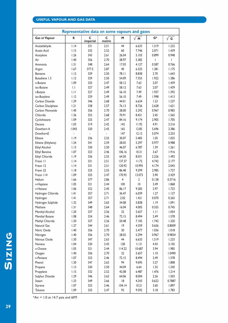
USEFUL VAPOUR AND GAS DATA
SIZ
IN
G
29
Representative data on some vapours and gasesGas or Vapour K C C M M G* G
imperial metricAcetaldehyde 1.14 331 2.51 44 6.633 1.519 1.232Acetic Acid 1.15 332 2.52 60 7.746 2.071 1.439Acetylene 1.26 343 2.61 26.04 5.103 0.899 0.948Air 1.40 356 2.70 28.97 5.382 1 1Ammonia 1.31 348 2.64 17.03 4.127 0.587 0.766Argon 1.67 377.5 2.87 40 6.325 1.381 1.175Benzene 1.12 329 2.50 78.11 8.838 2.70 1.643Butadiene 1.3 1.12 329 2.50 54.09 7.355 1.922 1.386n-Butane 1.09 325 2.47 58.12 7.63 2.07 1.439iso-Butane 1.1 327 2.49 58.12 7.63 2.07 1.439i-Butane 1.11 327 2.49 56.10 7.49 1.937 1.392iso-Butylene 1.12 329 2.49 56.10 7.49 1.998 1.413Carbon Dioxide 1.29 346 2.68 44.01 6.634 1.53 1.237Carbon Disulphate 1.21 338 2.57 76.13 8.726 2.628 1.621Carbon Monoxide 1.40 356 2.70 28.00 5.292 0.967 0.983Chloride 1.36 353 2.68 70.91 8.421 2.45 1.565Cyclohexane 1.09 325 2.47 84.16 9.174 2.905 1.705Decane 1.03 319 2.42 142 11.92 4.91 2.216Dowthern A 1.043 320 2.43 165 12.85 5.696 2.386DowthernE - - - 147 12.12 5.074 2.253Ethane 1.19 336 2.55 30.07 5.483 1.05 1.025Ethene (Ethylene) 1.24 341 2.59 28.05 5.297 0.977 0.988Ethyl Alcohol 1.13 330 2.50 46.07 6.787 1.59 1.261Ethyl Benzine 1.07 323 2.46 106.16 10.31 3.67 1.916Ethyl Chloride 1.19 336 2.55 64.50 8.031 2.226 1.492Freon 11 1.14 331 2.51 137.37 11.72 4.742 2.177Freon 12 1.14 331 2.51 120.92 10.995 4.174 2.043Freon 22 1.18 325 2.55 86.48 9.299 2.985 1.727Freon 114 1.09 325 2.47 170.93 13.073 5.90 2.429Helium 1.66 377 2.86 4 2 0.138 0.3716n-Heptane 1.05 321 2.44 100 10 3.49 1.868n-Hexane 1.06 322 2.45 86.17 9.283 2.97 1.723Hydrogen Chloride 1.41 357 2.71 36.47 6.039 1.27 1.127Hydrogen 1.41 357 2.71 2.02 1.421 0.070 0.265Hydrogen Sulphide 1.32 349 2.65 34.08 5.838 1.19 1.091Methane 1.31 348 2.64 16.04 4.005 0.555 0.745Menthyl Alcohol 1.20 337 2.56 32 5.657 1.11 1.054Menthyl Butane 1.08 324 2.46 72.15 8.494 2.49 1.578Methyl Chloride 1.20 337 2.56 50.48 7.105 1.742 1.320Natural Gas 1.27 344 2.61 19 4.359 0.656 0.8009Nitric Oxide 1.40 356 2.70 30 5.477 1.036 1.018Nitrogen 1.40 356 2.70 28.02 5.294 0.967 0.9834Nitrous Oxide 1.30 347 2.63 44 6.633 1.519 1.233Nonane 1.04 320 2.43 128 11.31 4.43 2.105n-Octane 1.05 321 2.44 114.22 10.687 3.94 1.985Oxygen 1.40 356 2.70 32 5.657 1.10 1.0490n-Pentane 1.07 323 2.46 72.15 8.494 2.49 1.578Phenol 1.30 347 2.63 94 9.695 3.27 1.808Propane 1.13 330 2.50 44.09 6.64 1.55 1.245Propylene 1.15 332 2.52 42.08 6.487 1.476 1.214Sulphur Dioxide 1.29 346 2.63 64.06 8.004 2.26 1.503Steam 1.33 349 2.66 18 4.243 0.622 0.7887Styrene 1.07 323 2.46 104.14 10.21 3.60 1.897Toluene 1.09 325 2.47 92 9.592 3.18 1.783
*Air = 1.0 at 14.7 psia and 600F.

CA
PA
CIT
Y
30
DN50 (2") DN80 (3") DN100 (4") DN150 (6") DN200 (8") DN250 (10") DN300 (12")
Set Press. Set Press. Set Press. Set Press. Set Press. Set Press. Set Press.
Min. Max. Min. Max. Min. Max. Min. Max. Min. Max. Min. Max. Min. Max.
2.5 70 2.5 70 2.5 70 2.5 70 2.5 70 2.5 70 2.5 70
70 800 70 800 70 800 70 800 70 800 70 800 70 800
2.5 70 2.5 70 2.5 70 2.5 70 2.5 70 2.5 70 2.5 70
70 3500 70 3500 70 3500 70 3000 70 2500 70 2000 70 2000
Over Press. Over Press. Over Press. Over Press. Over Press. Over Press. Over Press.
20% 40% 20% 40% 20% 40% 20% 40% 20% 40% 20% 40% 20% 40%
2.5 44 64 99 145 175 257 394 578 702 1029 1096 1608 1578 2316
5 62 91 140 205 248 364 557 817 992 1455 1550 2274 2232 3275
10 88 129 197 289 351 514 787 1155 1403 2058 2192 3215 3156 4630
20 124 182 279 409 496 727 1113 1633 1983 2909 3098 4545 4461 6545
30 152 223 341 501 607 890 1363 1999 2427 3561 3793 5564 5462 8012
40 175 257 394 378 700 1027 1573 2307 2802 4110 4378 6421 6304 9247
50 196 287 440 646 783 1148 1758 2578 3131 4592 4892 7176 7045 10333
60 214 314 482 707 857 1257 1925 2823 3428 5028 5357 7857 7714 11314
70 231 339 521 763 925 1357 2078 3048 3702 5428 5784 8482 8328 12214
70 127 180 285 405 507 720 1140 1616 2030 2879 3172 4498 4567 6478
80 136 192 305 433 542 769 1218 1727 2169 3076 3389 4807 4881 6921
90 144 204 323 459 575 815 1291 1831 2300 3261 3593 5096 5174 7338
100 151 215 341 483 606 859 1360 1929 2423 3436 3786 5369 5452 7731
200 213 302 480 680 853 1209 1916 2715 3412 4835 5332 7555 7678 10879
400 299 423 673 952 1196 1693 2687 3802 4786 6773 7478 10583 10769 15240
600 363 514 818 1156 1454 2055 3265 4615 5815 8220 9086 12844 13084 18496
800 416 588 937 1323 1666 2353 3741 5283 6664 9410 10413 14704 14994 21173
2.5 88 119 198 269 351 478 789 1073 1406 1912 2196 2987 3163 4302
5 124 169 280 380 497 676 1116 1518 1988 2704 3106 4224 4472 6083
10 176 239 395 538 703 956 1578 2106 2810 3822 4391 5973 6323 8601
20 248 338 559 760 993 1351 2230 3033 3973 5403 6207 8442 8938 12157
30 304 413 684 930 1216 1653 2730 3713 4863 6614 7599 10335 10943 14882
40 351 477 789 1074 1403 1908 3151 4286 5613 7634 8771 11928 12630 17176
50 392 533 882 1200 1568 2133 3522 4789 6273 8530 9802 13329 14115 19194
60 429 584 966 1313 1717 2335 3856 5244 6869 9340 10733 14594 15456 21015
70 464 630 1043 1418 1854 2521 4164 5661 7416 10083 11588 15755 16687 22688
70 190 270 427 608 760 1081 1706 2428 3038 4326 4707 6759 6836 9733
80 203 289 457 650 812 1155 1823 2595 3247 4622 5073 7222 7305 10399
90 215 306 484 689 860 1225 1932 2751 3442 4900 5378 7656 7745 11025
100 227 323 510 726 907 1291 2036 2898 3627 5162 5667 8066 8160 11615
200 319 454 718 1022 1277 1816 2867 4079 5107 7265 7980 11352 11492 16346
400 448 636 1007 1431 1791 2544 4022 5713 7163 10176 11193 15901 16118 22897
600 544 772 1224 1737 2176 3088 4886 6934 8704 12351 13600 19298 19584 27789
800 623 884 1403 1988 2494 3535 5600 7938 9974 14139 15585 22092 22443 31813
1000 692 980 1557 2205 2768 3920 6215 8802 11071 15679 17299 24499 24910 35279
2000 948 1338 2133 3011 3792 5352 8532 12019 15168 21409 23701 33452 34129 48171
2500 1046 1474 2353 3317 4182 5896 9392 13240 16730 23584 N/A N/A N/A N/A
3000 1131 1593 2546 3585 4525 6373 10162 14311 N/A N/A N/A N/A N/A N/A
3500 1208 1700 2718 3825 4832 6799 N/A N/A N/A N/A N/A N/A N/A N/A
121/121S/121SV/121SS/121V/121VS – ATMOSPHERIC VENTSSETTING
mbarg
Vac.Wt.Vac. Spr.Press.WtPress. Spr.
mbarg
VA
CU
UM
SE
TW
EIG
HT
LO
AD
ED
VA
CU
UM
SE
TS
PR
ING
LO
AD
ED
PR
ES
SU
RE
SE
TS
PR
ING
LO
AD
ED
PR
ES
SU
RE
SE
TW
EIG
HT
LO
AD
ED
Maximum setting limitations:- Aluminium 1000 mbarg/Plastic 200 mbarg.
AIR CAPACITY TABLES – NM3/h
CA
PA
CIT
Y
31
DN50 (2") DN80 (3") DN100 (4") DN150 (6") DN200 (8") DN250 (10") DN300 (12")
Set Press. Set Press. Set Press. Set Press. Set Press. Set Press. Set Press.
Min. Max. Min. Max. Min. Max. Min. Max. Min. Max. Min. Max. Min. Max.
2.5 70 2.5 70 2.5 70 2.5 70 2.5 70 2.5 70 2.5 70
70 800 70 800 70 800 70 800 70 800 70 800 70 800
2.5 70 2.5 70 2.5 70 2.5 70 2.5 70 2.5 70 2.5 70
70 3500 70 3500 70 3500 70 3000 70 2500 70 2000 70 2000
Over Press. Over Press. Over Press. Over Press. Over Press. Over Press. Over Press.
20% 40% 20% 40% 20% 40% 20% 40% 20% 40% 20% 40% 20% 40%
2.5 44 64 99 145 175 257 394 578 702 1029 1096 1608 1578 2316
5 62 91 140 205 248 364 557 817 992 1455 1550 2274 2232 3275
10 88 129 197 289 351 514 787 1155 1403 2058 2192 3215 3156 4630
20 124 182 279 409 496 727 1113 1633 1983 2909 3098 4545 4461 6545
30 152 223 341 501 607 890 1363 1999 2427 3561 3793 5564 5462 8012
40 175 257 394 378 700 1027 1573 2307 2802 4110 4378 6421 6304 9247
50 196 287 440 646 783 1148 1758 2578 3131 4592 4892 7176 7045 10333
60 214 314 482 707 857 1257 1925 2823 3428 5028 5357 7857 7714 11314
70 231 339 521 763 925 1357 2078 3048 3702 5428 5784 8482 8328 12214
70 127 180 285 405 507 720 1140 1616 2030 2879 3172 4498 4567 6478
80 136 192 305 433 542 769 1218 1727 2169 3076 3389 4807 4881 6921
90 144 204 323 459 575 815 1291 1831 2300 3261 3593 5096 5174 7338
100 151 215 341 483 606 859 1360 1929 2423 3436 3786 5369 5452 7731
200 213 302 480 680 853 1209 1916 2715 3412 4835 5332 7555 7678 10879
400 299 423 673 952 1196 1693 2687 3802 4786 6773 7478 10583 10769 15240
600 363 514 818 1156 1454 2055 3265 4615 5815 8220 9086 12844 13084 18496
800 416 588 937 1323 1666 2353 3741 5283 6664 9410 10413 14704 14994 21173
2.5 38 59 85 133 150 236 337 531 601 945 939 1477 1352 2127
5 53 84 120 188 212 334 477 750 850 1336 1328 2088 1912 3007
10 75 118 169 266 300 472 675 1061 1202 1890 1877 2952 2703 4271
20 106 167 239 376 425 668 954 1499 1698 2671 2654 4173 3822 6010
30 130 204 292 460 520 817 1167 1836 2079 3270 3249 5109 4679 7356
40 150 236 338 531 600 943 1347 2118 2400 3773 3750 5896 5400 8490
50 168 264 377 593 671 1054 1506 2367 2682 4217 4191 6599 6035 9488
60 184 289 413 649 734 1154 1649 2592 2937 4617 4589 7214 6608 10388
70 198 312 446 701 793 1246 1780 2798 3171 4984 4954 7788 7134 11215
70 128 188 287 423 511 752 1147 1689 2043 3008 3192 4700 4597 6768
80 136 201 307 452 546 803 1226 1804 2183 3214 3411 5022 4912 7231
90 145 213 326 479 579 852 1299 1913 2315 3407 3617 5324 5208 7666
100 152 224 343 505 610 897 1369 2015 2439 3590 3811 5609 5488 8077
200 215 316 483 710 859 1263 1928 2836 3435 5052 5367 7893 7728 11367
400 301 442 677 995 1204 1769 2704 3973 4817 7076 7527 11057 10839 15922
600 366 537 823 1208 1463 2147 3286 4821 5853 8588 9146 13419 13170 19324
800 419 614 943 1383 1677 2458 3766 5520 6708 9832 10481 15362 15092 22122
1000 465 681 1047 1533 1861 2726 4180 6121 7445 10903 11633 17036 16752 24532
2000 638 930 1434 2094 2550 3722 5727 8358 10201 14887 15939 23261 22952 33496
2500 703 1025 1582 2306 2813 4100 6316 9207 11251 16400 N/A N/A N/A N/A
3000 761 1108 1712 2493 3043 4431 6834 9951 N/A N/A N/A N/A N/A N/A
3500 812 1182 1828 2660 3250 4728 N/A N/A N/A N/A N/A N/A N/A N/A
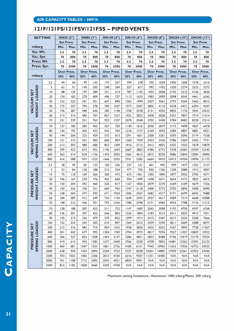
121F/121FS/121FSV/121FSS – PIPED VENTS
SETTING
mbarg
Vac.Wt.Vac. Spr.Press.WtPress. Spr.
mbarg
VA
CU
UM
SE
TW
EIG
HT
LO
AD
ED
VA
CU
UM
SE
TS
PR
ING
LO
AD
ED
PR
ES
SU
RE
SE
TS
PR
ING
LO
AD
ED
PR
ES
SU
RE
SE
TW
EIG
HT
LO
AD
ED
Maximum setting limitations:- Aluminium 1000 mbarg/Plastic 200 mbarg.
AIR CAPACITY TABLES – NM3/h

CA
PA
CIT
Y
32
DN50 (2") DN80 (3") DN100 (4") DN150 (6") DN200 (8") DN250 (10") DN300 (12") DN400 (16")
Set Press. Set Press. Set Press. Set Press. Set Press. Set Press. Set Press. Set Press.
Min. Max. Min. Max. Min. Max. Min. Max. Min. Max. Min. Max. Min. Max. Min. Max.
2.5 70 2.5 70 2.5 70 2.5 70 2.5 70 2.5 70 2.5 70 2.5 70
70 800 70 800 70 800 70 800 70 800 70 800 70 800 70 800
Over Press. Over Press. Over Press. Over Press. Over Press. Over Press. Over Press. Over Press.
20% 40% 20% 40% 20% 40% 20% 40% 20% 40% 20% 40% 20% 40% 20% 40%
2.5 45 64 101 145 180 257 404 578 719 1029 1124 1608 1618 2316 2877 41175 64 91 143 205 254 364 571 817 1017 1455 1589 2274 2288 3275 4068 5822
10 90 129 202 289 359 514 807 1155 1438 2058 2247 3215 3235 4630 5751 823120 127 182 286 409 508 727 1141 1633 2032 2909 3176 4545 4573 6545 8130 1163530 156 223 350 501 622 890 1397 1999 2488 3561 3888 5564 5599 8012 9953 1424340 179 257 404 578 718 1027 1612 2307 2872 4110 4487 6421 6462 9247 11488 1643950 201 287 451 646 802 1148 1802 2578 3210 4592 5015 7176 7222 10333 12838 1837060 220 314 494 707 879 1257 1973 2823 3514 5028 5491 7857 7907 11314 14058 2011370 237 339 534 763 949 1357 2130 3048 3794 5428 5929 8482 8537 12214 15178 21714
70 127 180 285 405 507 720 1140 1616 2030 2879 3172 4498 4567 6478 8120 1151680 136 192 305 433 542 769 1218 1727 2169 3076 3389 4807 4881 6921 8676 1230590 144 204 323 459 575 815 1291 1831 2300 3261 3593 5096 5174 7338 9199 13045
100 151 215 341 483 606 859 1360 1929 2423 3436 3786 5369 5452 7731 9692 13744200 213 302 480 680 853 1209 1916 2715 3412 4835 5332 7555 7678 10879 13649 19341400 299 423 673 952 1196 1693 2687 3802 4786 6773 7478 10583 10769 15240 19144 27093600 363 514 818 1156 1454 2055 3265 4615 5815 8220 9086 12844 13084 18496 23261 32881800 416 588 937 1323 1666 2353 3741 5283 6664 9410 10413 14704 14994 21173 26657 37642
401/451 – SIDE MOUNTED VACUUM VALVES
501/551 – BOTTOM MOUNTED LOW PRESSURESAFETY or SIDE MOUNTED VACUUM VALVES
SETTING
mbarg
401 Wt.451 Spr.
mbarg
401
–VA
CU
UM
SE
TW
EIG
HT
LO
AD
ED
451
– V
AC
UU
M S
ET
SP
RIN
G L
OA
DE
D
DN50 (2") DN80 (3") DN100 (4") DN150 (6") DN200 (8") DN250 (10") DN300 (12") DN400 (16")
Set Press. Set Press. Set Press. Set Press. Set Press. Set Press. Set Press. Set Press.
Min. Max. Min. Max. Min. Max. Min. Max. Min. Max. Min. Max. Min. Max. Min. Max.
2.5 70 2.5 70 2.5 70 2.5 70 2.5 70 2.5 70 2.5 70 2.5 70
2.5 70 2.5 70 2.5 70 2.5 70 2.5 70 2.5 70 2.5 70 2.5 70
70 3500 70 2800 70 2100 70 2100 70 2100 70 2000 70 2000 70 1500
70 800 70 800 70 800 70 800 70 800 70 800 70 800 70 800
Over Press. Over Press. Over Press. Over Press. Over Press. Over Press. Over Press. Over Press.
20% 40% 20% 40% 20% 40% 20% 40% 20% 40% 20% 40% 20% 40% 20% 40%
2.5 38 59 85 133 150 236 337 531 601 945 939 1477 1352 2127 2404 37805 53 84 120 188 212 334 477 750 850 1336 1328 2088 1912 3007 3399 5346
10 75 118 169 266 300 472 675 1061 1202 1890 1877 2952 2703 4271 4806 755820 106 167 239 376 425 668 954 1499 1698 2671 2654 4173 3822 6010 6794 1068430 130 204 292 460 520 817 1167 1836 2079 3270 3249 5109 4679 7356 8317 1307840 150 236 338 531 600 943 1347 2118 2400 3773 3750 5896 5400 8490 9600 1509450 168 264 377 593 671 1054 1506 2367 2682 4217 4191 6599 6035 9488 10729 1686760 184 289 413 649 734 1154 1649 2592 2937 4617 4589 7214 6608 10388 11748 1846870 198 312 446 701 793 1246 1780 2798 3171 4984 4954 7788 7134 11215 12683 19938
70 128 188 287 423 511 752 1147 1689 2043 3008 3192 4700 4597 6768 8173 1203180 136 201 307 452 546 803 1226 1804 2183 3214 3411 5022 4912 7231 8733 1285690 145 213 326 479 579 852 1299 1913 2315 3407 3617 5324 5208 7666 9259 13629
100 152 224 343 505 610 897 1369 2015 2439 3590 3811 5609 5488 8077 9756 14359200 215 316 483 710 859 1263 1928 2836 3435 5052 5367 7893 7728 11367 13739 20207400 301 442 677 995 1204 1769 2704 3973 4817 7076 7527 11057 10839 15922 19270 28306600 366 537 823 1208 1463 2147 3286 4821 5853 8588 9146 13419 13170 19324 23413 34353800 419 614 943 1383 1677 2458 3766 5520 6708 9832 10481 15362 15092 22122 26831 39327
1000 465 681 1047 1533 1861 2726 4180 6121 7445 10903 11633 17036 16752 24532 29781 436122000 638 930 1434 2094 2550 3722 5727 8358 10201 14887 15939 23261 22952 33496 N/A N/A2100 651 950 1466 2139 2606 3802 5863 8555 10423 15208 N/A N/A N/A N/A N/A N/A2800 739 1076 1662 2421 N/A N/A N/A N/A N/A N/A N/A N/A N/A N/A N/A N/A3500 812 1182 N/A N/A N/A N/A N/A N/A N/A N/A N/A N/A N/A N/A N/A N/A
SETTING
mbarg
501 Wt. Press.501 Wt.Vac.551 Spr. Press.551 Spr.Vac.
mbarg
501
– S
ET
TIN
GW
EIG
HT
LO
AD
ED
551
– S
ET
TIN
GS
PR
ING
LO
AD
ED
Maximum setting limitations:Aluminium 1000 mbarg/Plastic 200 mbarg.
Maximum setting limitations:Plastic 200 mbarg.
AIR CAPACITY TABLES – NM3/h

CA
PA
CIT
Y
33
DN50 (2") DN80 (3") DN100 (4") DN150 (6") DN200 (8") DN250 (10") DN300 (12") DN400 (16")
Set Press. Set Press. Set Press. Set Press. Set Press. Set Press. Set Press. Set Press.
Min. Max. Min. Max. Min. Max. Min. Max. Min. Max. Min. Max. Min. Max. Min. Max.
2.5 70 2.5 70 2.5 70 2.5 70 2.5 70 2.5 70 2.5 70 2.5 70
70 3500 70 2800 70 2100 70 2100 70 2100 70 2000 70 2000 70 1500
Over Press. Over Press. Over Press. Over Press. Over Press. Over Press. Over Press. Over Press.
20% 40% 20% 40% 20% 40% 20% 40% 20% 40% 20% 40% 20% 40% 20% 40%
2.5 88 119 198 269 351 478 789 1073 1406 1912 2196 2987 3163 4302 5622 76485 124 169 280 380 497 676 1116 1518 1988 2704 3106 4224 4472 6083 7950 10814
10 176 239 395 538 703 956 1578 2106 2810 3822 4391 5973 6323 8601 11241 1529020 248 338 559 760 993 1351 2230 3033 3973 5403 6207 8442 8938 12157 15891 2161330 304 413 684 930 1216 1653 2730 3713 4863 6614 7599 10335 10943 14882 19454 2645740 351 477 789 1074 1403 1908 3151 4286 5613 7634 8771 11928 12630 17176 22454 3053550 392 533 882 1200 1568 2133 3522 4789 6273 8530 9802 13329 14115 19194 25093 3412260 429 584 966 1313 1717 2335 3856 5244 6869 9340 10733 14594 15456 21015 27477 3736170 464 630 1043 1418 1854 2521 4164 5661 7416 10083 11588 15755 16687 22688 29666 40334
70 190 270 427 608 760 1081 1709 2433 3038 4326 4747 6759 6836 9733 12153 1730280 203 289 457 650 812 1155 1823 2595 3247 4622 5073 7222 7305 10399 7305 1848890 215 306 484 689 860 1225 1932 2751 3442 4900 5378 7656 7745 11025 7745 19600
100 227 323 510 726 907 1291 2036 2898 3627 5162 5667 8066 8160 11615 14507 20650200 319 454 718 1022 1277 1816 2867 4079 5107 7265 7980 11352 11492 16346 20430 29060400 448 636 1007 1431 1791 2544 4022 5713 7163 10176 11193 15901 16118 22897 28654 40707600 544 772 1224 1737 2176 3088 4886 6934 8704 12351 13600 19298 19584 27789 34816 49403800 623 884 1403 1988 2494 3535 5600 7938 9974 14139 15585 22092 22443 31813 39898 56557
1000 692 980 1557 2205 2768 3920 6215 8802 11071 15679 17299 24499 24910 35279 44285 627182000 948 1338 2133 3011 3792 5352 8532 12019 15168 21409 23701 33452 34129 48171 N/A N/A2100 969 1367 2180 3076 3875 5467 8719 12302 15499 21870 N/A N/A N/A N/A N/A N/A2800 1098 1547 2471 3481 N/A N/A N/A N/A N/A N/A N/A N/A N/A N/A N/A N/A3500 1208 1700 N/A N/A N/A N/A N/A N/A N/A N/A N/A N/A N/A N/A N/A N/A
601/651 – LOW PRESSURE SAFETY VALVES ATMOSPHERIC VENTS
785/786 – EMERGENCY VENTS
SETTING
mbarg
601 Wt.651 Spr.SETTINGmbarg
601
– P
RE
SS
UR
E S
ET
WE
IGH
T L
OA
DE
D65
1 –
PR
ES
SU
RE
SE
TS
PR
ING
LO
AD
ED
DN250 (10") DN300 (12") DN400 (16") DN450 (18") DN200 (20") DN600 (24") DN750 (30") DN800 (32") DN900 (36")
Over Press. Over Press. Over Press. Over Press. Over Press. Over Press. Over Press. Over Press. Over Press.
20% 40% 20% 40% 20% 40% 20% 40% 20% 40% 20% 40% 20% 40% 20% 40% 20% 40%
2.5 N/A N/A N/A N/A N/A N/A 576 820 576 820 576 820 576 820 576 820 576 82010 N/A N/A N/A N/A N/A N/A 1151 1640 1151 1640 1151 1640 1151 1640 1151 1640 1151 164020 N/A N/A N/A N/A N/A N/A 1627 2318 1627 2318 1627 2318 1627 2318 1627 2318 1627 231830 N/A N/A N/A N/A N/A N/A 1992 2837 1992 2837 1992 2837 1992 2837 1992 2837 1992 283740 N/A N/A N/A N/A N/A N/A 2300 3275 2300 3275 2300 3275 2300 3275 2300 3275 2300 3275
250 N/A N/A N/A N/A N/A N/A 5698 8103 5698 8103 5698 8103 5698 8103 5698 8103 5698 8103
4.5 2435 2630 3506 3787 6234 6733 7890 8521 9740 10520 14026 15149 21915 23670 24935 26932 31558 3408510 3629 3920 5226 5644 9290 10034 11758 12699 14516 15678 20904 22577 32662 35276 37162 40137 47033 5079820 5130 5540 7387 7978 13133 14183 16622 17951 20521 22162 29550 31913 46171 49864 52533 56734 66487 7180440 7249 7828 10438 11272 18557 20039 23487 25361 28996 31310 41754 45087 65241 70448 74229 80154 93947 10144560 8871 9577 12774 13791 22709 24518 28741 31031 35482 38309 51095 55165 79835 86196 90835 98072 114963 12412280 10234 11048 14737 15909 26200 28283 33159 35796 40937 44192 58949 63636 92108 99432 104789 113131 132635 143182
100 11432 12340 16463 17769 29267 31590 37041 39981 45730 49359 65851 71077 102893 111058 117069 126360 148165 159924120 12513 13504 18019 19446 32034 34571 40543 43754 50052 54017 72075 77785 112618 121539 128134 138284 162170 175015140 13504 14572 19446 20984 34571 37304 43754 47213 54017 58288 77785 83934 121159 131148 138284 149217 175015 188852
SETTINGmbarg
786
VA
CU
UM
SPR
ING
LO
AD
PR
ESS
UR
E S
ET
WE
IGH
T L
OA
DE
D
SETTINGS
Weight Loaded Spring LoadedPressure Vacuum
Min mbarg Max mbarg Min mbarg Max mbarg
4.5 140 2.5 250
NOTE:The 786 vacuum capacity is based on a nominalDN200 (8") vacuum valve, which is fitted to allsizes DN450 (18") and above.
AIR CAPACITY TABLES – NM3/h
Maximum setting limitations: Aluminium 1000 mbarg/Plastic 200 mbarg.
Maximum setting limitations: Plastic 200 mbarg.

TE
RM
SA
ND
DE
FIN
IT
IO
NS
34
For the purpose of this catalogue the following Termsand Definitions have been applied from API2000.
Accumulation:The pressure increase in a tank over its maximumallowable working pressure when the vent valve isrelieving (expressed in pressure units or percentageof the maximum allowable working pressure).Maximum allowable accumulations are typicallyestablished by applicable codes for operating and firecontingencies.
Barrel:A liquid unit of measure equal to 42 US gallons(0.159 cubic metres).
BTU:British Thermal Unit, a unit of heat that will increasethe temperature of one pound of water one degreeFahrenheit.
Emergency venting:The venting required when an abnormal condition,such as ruptured internal heating coils or an externalfire, exists either inside or outside of a tank.
Normal venting:The venting required because of operationalrequirements or atmospheric changes.
Overpressure:The pressure increase at the valve inlet above the setpressure, when the valve is relieving, expressed as apercentage of the set pressure. It is the same asaccumulation when the valve is set at the maximumallowable working pressure and the inlet piping lossesare zero.
Petroleum:Crude oil.
Petroleum products:Hydrocarbon materials or other products derivedfrom crude oil.
PV valve:A weight-loaded, pilot-operated or spring-loadedvalve, used to relieve excess pressure and/or vacuumthat has developed in a tank.
Rated relieving capacity:The flow capacity of a relief device expressed interms of air flow at standard conditions (SCFH orNm3/h) at a designated pressure or vacuum.
Relief device:Any device used to relieve excess pressure and/orvacuum that has developed in a tank.
Relieving pressure:The pressure at the inlet of a relief device when it isflowing at the required relieving capacity.
Required flow capacity:The flow capacity of a relief device required toprevent excessive pressure or vacuum in a tank underthe most severe operating or emergency conditions.
SCFH:Standard cubic feet of air or gas per hour (same asfree air or free gas) at a temperature of 600 F(15.60 C) and a pressure of 14.7 pounds per squareinch absolute (1.014 bar absolute).
Nm3/h:Normal cubic meters of air or gas per hour at atemperature of 00 C and pressure of 1.014 bar.
Set pressure:The gauge pressure at the device inlet at which therelief device is set to start opening under serviceconditions (measurable lift begins).
Thermal inbreathing:The movement of air or blanketing gas into a tankwhen vapours in the tank contract or condense as aresult of weather changes (e.g. a decrease inatmospheric temperature).
Thermal outbreathing:The movement of vapours out of a tank whenvapours in the tank expand and liquid in the tankvapourises as a result of weather changes (e.g. anincrease in atmospheric temperature).
Wetted area:The surface area of a tank exposed to liquid on theinterior and heat from a fire on the exterior.
TERMS AND DEFINITIONS

US
EF
UL
CO
NV
ER
SIO
NS
35
REQUIRED UNITS
Ft/sec Ft/min M/sec M/min Km/hr
Ft/sec 60 0.3048 18.288 1.09728
Ft/min 0.01667 0.00508 0.3048 0.01829
M/sec 3.28084 196.85 60 3.6
M/min 0.05468 3.28084 0.016670 0.06
Km/hr 0.91134 5.468E+01 0.27777 16.6667
REQUIRED UNITS
mm inch inchmbarg barg psig water water Mercury kpag kg/cm2g oz/in2g
mbarg 0.001 0.0145 10.21 0.4019 0.02961 0.1 0.00102 0.232
barg 1000 14.5 10207 401.9 29.61 100 1.0197 232.1
psig 68.95 0.0689 703.8 27.71 2.042 6.895 0.0703 16
mm water 0.098 0.0001 0.001421 0.0394 0.0029 0.0098 0.0001 0.0227
inch water 2.488 0.0025 0.03609 25.4 0.0737 0.2488 0.0025 0.5775
inch Mercury 33.77 0.0338 0.4898 344.7 13.57 3.377 0.0344 7.836
kpag 10 0.01 0.145 102.1 4.019 0.2961 0.0102 2.321
kg/cm2g 980.7 0.9807 14.22 10010 394.1 29.04 98.07 227.6
oz/in2g 4.309 0.0043 0.0625 43.99 1.732 0.1276 0.4309 0.0044
PRESSUREG
IVE
N U
NIT
S
REQUIRED UNITS
ft3 Litres M3 US gal. Barrel
ft3 28.317 0.02832 7.4805 0.1781
Litres 0.0351 0.001 0.26417 0.00629
M3 35.3147 1000 264.172 6.28981
US gal. 0.13368 3.78451 0.003785 0.00283
Barrel 5.61458 158.9873 0.15899 42
VOLUME
GIV
EN
UN
ITS
REQUIRED UNITS
in2 ft2 Sq Yards m2 mm2
in2 0.006944 0.0007716 0.00064516 645.6
ft2 144 0.11111 0.0929 92900
Sq Yards 1296 9 0.83613 836100
m2 1550 10.764 1.196000 1xE+06
mm2 0.00155 1.076E-05 1.196xE-06 1xE-06
AREA
GIV
EN
UN
ITS
VELOCITY
GIV
EN
UN
ITS
REQUIRED UNITS
Ounces Pounds Kgs Tonnes Grams
Ounces 0.0625 0.02835 2.835xE-05 28.3495
Pounds 16 0.45359 4.536xE-04 453.59
Kgs 35.274 2.2046 0.001 1000
Tonnes 35274 2204.623 1000.000000 1xE+06
Grams 0.03527 2.205E-03 0.00100 1xE-06
MASS
GIV
EN
UN
ITS
REQUIRED UNITS
Inches Feet Yards mm Metres
Inches 0.83333 0.02777 25.4 0.0254
Feet 12 0.33333 304.800000 0.3048
Yards 36 3 914.4 0.9144
mm 0.03937 0.00328 0.001936 0.001
Metres 39.37 3.2808 1.0936 1000
LENGTH
GIV
EN
UN
ITS
USEFUL CONVERSIONS
Required Units=
Given Unitsx
Chart Factor

TR
AN
SP
OR
TA
TIO
NP
RO
TE
CT
IO
N
36
DischargeSet Pressure Capacity
IMCO Ref. Barg m3/h AIR
IMCO1-4 4.40 11696
IMCO1-3 3.71 10156
IMCO2 2.17 9266
3.31 6722
The Marvac - Megaflo fig 011Is a Pressure/Vacuum or Pressure only safety reliefvalve, designed to be compact yet achieve highdischarge capacities.These two stringentrequirements are demanded by Road, Rail andContainer Tank manufacturers to minimise size andweight, yet maximise protection.
The valves are manufactured in 316 stainless steeland can be electrochemically polished for use inhygienic applications. Seal materials are FEPencapsulated “O” rings ensuring compatibility withhighly corrosive media.A flame gauze can be fittedfor use on flammable processes. Seal life is maximisedby having a metal back-up seat, which gives continuedprotection in the event of seal failure.
The Marvac “MEGAFLO” Valve
The Marston “TANK-A-VENT” Bursting Disc
Materials: Body 316ssInternals 316ssSeals FEP/PTFE
Size: 21/2"
Connections: Screwed BSPFlanged available
Standard Vacuum Setting = 0.203 Barg
The Marston “TANK-A-VENT”Bursting Disc is specificallydesigned for the protection ofsafety valves on road and railtankers.
- Suitable for Gas or Liquidapplications.
- Non fragmentational.- Simple one piece installation.- Available with support forvacuum operation.
- No holder required.- Wide range of materialoptions available.
92m
m m
ax

37

P r o d u c t R a n g e
GAUGE HATCH
PRESSURE VACUUM
PLASTIC PRESSURE VACUUM
TANK BLANKETING
PILOT OPERATED
MANWAY/EMERGENCY VENT TRANSPORTATION VALVE
P l e a s e c o m p l e t e t h e f o l l ow i n g
Name:
Position:
Company:
Address:
Post Code:
Tel No:
Fax No:
Email:
Bailey Birkett Sales DivisionSharp Street,Worsley Manchester, UKM28 3NATel: +44 (0)161 703 1888Fax: +44 (0)161 703 1985 / 8451Email: [email protected] site: www.baileybirkett.com
Simply photocopy andfax to us for moreinformation on. . .
P l e a s e t i c k b o xw h e r e a p p r o p r i a t e
F a x b a c k t o u s o n
Fax: +44 (0)161 703 1985
Bailey Safety Relief Valves
Marston Bursting Discs & Explosion Vent Panels
Amal Flame Arresters
Birkett API/ASME Spring & Pilot SRV’s
Bailey Pressure Reducing Valves
L O C A L AG E N T
Assistance:
Our experienced and fully trained team of Technical Sales Engineers
and agents are available to give advice and assistance on the sizing
and selection of the Marvac Product Range.
This service is available to you by calling your local agent or our
Marvac Technical Sales Department, who will be happy to help.
Details of our worldwide network of distributors and regional
offices are available on our website.
MVPR0204 Registered Office:Victoria Road, Leeds, LS11 5UG, UK.