marley-cooling tower
DESCRIPTION
Cooling Tower NCF TS 09TRANSCRIPT

/ Marley NC® Fiberglass Cooling Tower /Engineering Data & Specifications

NC Fiberglass Cooling Tower / Engineering Data: Contents 2
Engineering Data
Sound Control 4Water Quality 5Schematics 6Piping Connections 10Support 16Freeze Prevention 18
Specifications / Base
Base 19Thermal Performance 19Performance Warranty 19Design Loading 20Construction 20Mechanical Equipment 21Fill, Louvers and Drift Eliminators 22Hot Water Distribution System 23Casing, Fan Deck and Fan Guard 23Access 23Collection Basin 24Scope of Work 24
Specifications / Options
Stainless Steel Structure 25
Convenience and Safety OptionsGuardrail and Ladder 25Ladder Extension 25Ladder Safety Cage 25Additional Ladder 26Access Door Ladder 26Ladder Safety Gate 26Plenum Walkway 26Interior Mechanical Equipment Access Platform 26
Miscellaneous OptionsSound Control 27Quiet Fan 27Single Hot Water Inlet 270.40mm PVC Fill 28Fan Cylinder Extension 28

NC Fiberglass Cooling Tower / 3
NC Fiberglass towers are fiberglass with steel sub-structure, field-erected, crossflow cooling towers,
designed to serve air conditioning and refrigeration systems as well as light to medium industrial process loads on clean water. The Marley NC Fiberglass cooling tower has been design specifically for sound control and tonnage density and incorporates field-proven, industrial-quality components.
The specifications portion of this publication not only relates the language to use in describing an appropriate NC Fiberglass cooling tower—but also defines why certain items and features are important enough to specify and to insist upon compliance by all bidders. The left hand column of pages 18 thru 28 provides appropriate text for the various specification paragraphs, whereas the right hand column comments on the meaning of the subject matter and explains its value.
Pages 18 thru 28 indicate those paragraphs which will result in the purchase of a basic cooling tower—one that accomplishes the specified thermal performance, but which will lack many operation—and maintenance-enhancing accessories and features that are usually desired by those persons who are responsible for the operation of the system. It will also incorporate those standard materials which testing and experience has proven to provide acceptable longevity in normal operating conditions.
Pages 25 thru 28 provide paragraphs intended to add those features, components and materials that will customize the cooling tower to meet the user‘s requirements.
NC Fiberglass Cooling Tower / Engineering Data: Sound Control 4
The NC—Quiet by Design
The NC is the result of extensive design studies focused on cooling tower sound control. These studies were complicated by the fact that the cooling tower market is typically driven by one of two powerful, yet often conflicting requirements. The most common is for a cooling tower that provides the required heat rejection capacity with a high level of reliability at low cost. Sound control, while important, is not the primary consideration for this application.
The other requirement, which is becoming ever more important in our crowded, fast-paced society, is driven by conditions that demand the lowest practical sound level. Energy efficiency, reliability, and ease of maintenance, while still extremely important, are not the highest priorities
In the first case, sound is important, while in the second case it is extremely important. To best satisfy these two competing market requirements we created choices through key mechanical equipment selections, to control sound. The result is more options than any other cooling tower on the market today.
The result is a line of towers capable of meeting all but the most restrictive noise limitations—and that will react favorably to natural attenuation. Where the tower has been sized to operate within an enclosure, the enclosure itself will have a damping effect on sound. Sound also declines with distance—by about 6 dBA each time the distance doubles.
All standard NC cooling towers are equipped with low sound fans. This in combination with zero-splash crossflow film-fill results in a line of towers capable of meeting most noise limitations. Where noise at a critical point is likely to exceed an acceptable limit, several other options are available—listed below in ascending order of cost impact:
• The Marley "Quiet Package" includes the affordable Quiet Fan mechanical option, optimized to achieve the lowest possible sound levels while maintaining efficiency.
Enclosures
Occasionally, cooling towers are located inside architectural enclosures for aesthetic reasons. Although NC Class towers adapt well to enclosures, the designer must realize the potential impact of a poorly arranged enclosure on the tower’s performance and operation. The designer must take care to provide generous air inlet paths, and the tower’s fan cylinder discharge height should not be lower than the elevation of the top of the enclosure. Marley Technical Report #H-004 “External Influences on Cooling Tower Performance” is available at spxcooling.com or from your Marley sales representative.
As suggested in the aforementioned Technical Report, it may also be advisable to specify a design wet-bulb temperature 1⁄2°C higher than normal to compensate for potential recirculation initiated by the enclosure. You’ll benefit from discussing your project with your Marley sales representative.

NC Fiberglass Cooling Tower / Engineering Data: Water Quality 5
CAUTIONThe cooling tower must be located at such distance and direction to avoid the possibility of contaminated discharge air being drawn into building fresh air intake ducts. The purchaser should obtain the services of a Licensed Professional Engineer or Registered Architect to certify that the location of the cooling tower is in compliance with applicable air pollution, fire and clean air codes.
System Cleanliness
Cooling towers are very effective air washers. Atmospheric dust able to pass through the relatively small louver openings will enter the circulating water system. Increased concentrations can intensify system maintenance by clogging screens and strainers—and smaller particulates can coat system heat transfer surfaces. In areas of low flow velocity—such as the cold water basin—sedimentary deposits can provide a breeding ground for bacteria.
In areas prone to dust and sedimentation, you should consider installing some means for keeping the cold water basin clean. Typical devices include side stream filters and a variety of filtration media.
Water Treatment
To control the buildup of dissolved solids resulting from water evaporation, as well as airborne impurities and biological contaminants including Legionella, an effective consistent water treatment program is required. Simple blowdown may be adequate to control corrosion and scale, but biological contamination can only be controlled with biocides.
An acceptable water treatment program must be compatible with the variety of materials incorporated in a cooling tower—ideally the pH of the circulating water should fall between 6.5 and 8.0. Batch feeding of chemicals directly into the cooling tower is not a good practice since localized damage to the tower is possible. Specific startup instructions and additional water quality recommendations can be found in the NC User Manual which accompanies the tower and also is available from your local Marley sales representative. For complete water treatment recommendations, consult a competent, qualified water treatment supplier.
Typical Applications
The NC tower is an excellent choice for normal applications requiring cold water for the dissipation of heat. This includes condenser water cooling for air conditioning, refrigeration, and thermal storage systems, as well as their utilization for free-cooling in all of those systems. The NC can also be used in the cooling of jacket water for engines and air compressors, and are widely applied to dissipate waste heat in a variety of industrial, power and manufacturing processes.
Choosing the stainless steel sub-structure option, the NC can be confidently applied in unusually corrosive processes and operating environments. However, no single product line can answer all problems, and selective judgement should be exercised in the following situations
Applications Requiring Alternative Cooling Tower Selections
Certain types of applications are incompatible with any cooling tower with film fill—whether NC or a competitive tower of similar manufacture. Film fill is subject to distortion in high water temperatures, and the narrow passages are easily clogged by turbid or debris-laden water. Some of the applications, which call for alternative tower designs are:
• Water temperatures exceeding 52°C—adversely affects the service life and performance of normal PVC fill. Higher temperature fill materials are available.
• Ethylene glycol content—can plug fill passages as slime and algae accumulate to feed on the available organic materials.
• Fatty acid content—found in processes such as soap and detergent manufacturing and some food processing—fatty acids pose a serious threat for plugging fill passages.
• Particulate carry over—often found in steel mills and cement plants—can both cause fill plugging, and can build up to potentially damaging levels on tower structure.
• Pulp carry over—typical of the paper industry and food processing where vacuum pumps or barometric condensers are used. Causes fill plugging which may be intensified by algae.
Alternative Selections
In addition to the NC, SPX Cooling Technologies offers a full scope of products in various designs and capacities to meet the special demands of specific applications.
spxcooling.com—visit us on the web for a complete list of products, services, publications and to find your nearest sales representative.
NC Fiberglass Cooling Tower / Engineering Data: Schematic 6
HINSTALLED
HEIGHT
W
HINGED ACCESSDOOR
A MIN
MIN89
CL CL
L
PLAN
SIDE ELEVATION AIR INLET ELEVATION
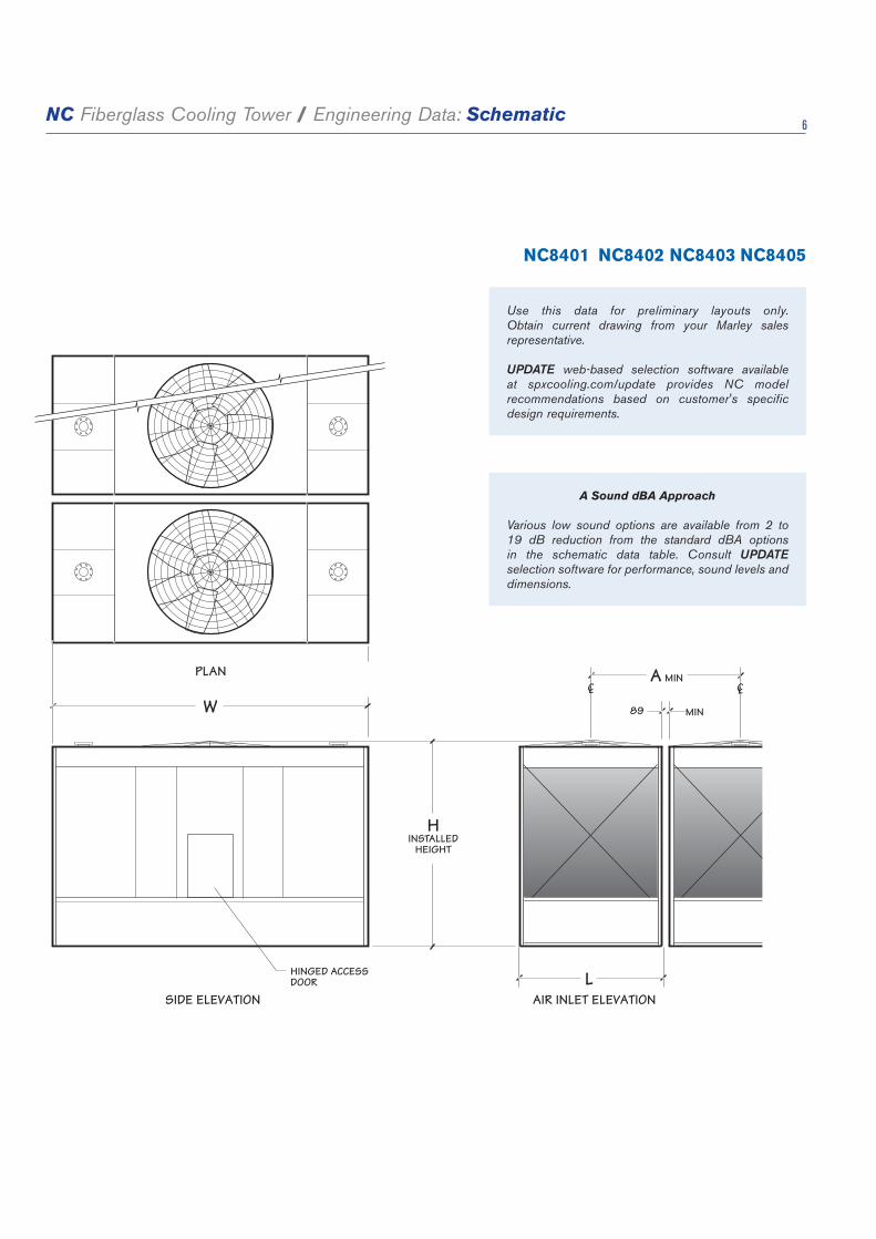
NC8401 NC8402 NC8403 NC8405
Use this data for preliminary layouts only. Obtain current drawing from your Marley sales representative.
UPDATE web-based selection software available at spxcooling.com/update provides NC model recommendations based on customer's specific design requirements.
A Sound dBA Approach
Various low sound options are available from 2 to 19 dB reduction from the standard dBA options in the schematic data table. Consult UPDATE selection software for performance, sound levels and dimensions.

NC Fiberglass Cooling Tower / Engineering Data: Schematic Data 7
NOTE1 Use this bulletin for preliminary layouts only. Obtain current
drawings from your Marley sales representative. All table data is per cell.
2 Last numeral of model number indicates number of cells. Change as appropriate for your selection.
3 Nominal cooling capacity based upon 37°C HW, 32°C CW, 28°C WB. The UPDATE web-based selection software provides NC model recommendations based on specific design requirements.
4 Standard overflow is a 4" dia. standpipe in the collection basin floor. The standpipe removes for flush-out and draining. See page 14 for side overflow option.
5 Outlet sizes vary according to flow and arrangement. See pages 14 and 15 for outlet sizes and details.
6 Makeup water connection may be 1" or 2" dia., depending upon tower heat load, water pressure and desired connections. See page 11 for additional information.
NC8401 NC8402 NC8403 NC8405
Model note 2
Nominal Capacity
m3/hr note 3
Motor kW
dBA 1.5m from
air inlet face
Design Operating
Weight kg
Dimensions
L W H A
NC8401G-1 83 1.5 63
3547 1988 3912 3105 2077
NC8401H-1 96 2.2 65
NC8401K-1 114 3.7 71
NC8401M-1 130 5.5 73
NC8401N-1 143 7.5 76
NC8401P-1 162 11 78
NC8402G-1 107 1.5 64
4449 2559 4318 3124 2648
NC8402H-1 121 2.2 65
NC8402K-1 143 3.7 68
NC8402M-1 167 5.5 74
NC8402N-1 186 7.5 76
NC8402P-1 209 11 79
NC8402Q-1 226 15 81
NC8403K-1 173 3.7 68
6861 2559 5537 3638 2648
NC8403M-1 198 5.5 72
NC8403N-1 224 7.5 76
NC8403P-1 254 11 79
NC8403Q-1 278 15 80
NC8403R-1 298 18.5 81
NC8403S-1 314 22 84
NC8403T-1 344 30 85
NC8405N-1 269 7.5 74
8067 3016 6071 3651 3105
NC8405P-1 306 11 76
NC8405Q-1 334 15 78
NC8405R-1 360 18.5 81
NC8405S-1 383 22 84
NC8405T-1 417 30 87

NC Fiberglass Cooling Tower / Engineering Data: Schematic 8
W
3651INSTALLED
HEIGHT
5023INSTALLED
HEIGHT
HINGED ACCESSDOOR
A MIN
MIN
CL CL
L
VELOCITY RECOVERYCYLINDER INCREASES MODEL PERFORMANCE. REFER TO DATA TABLE AND UPDATE FORADDITIONAL INFORMATION.FAN GUARD NOT REQUIRED.
PLAN
SIDE ELEVATION AIR INLET ELEVATION
89
NC8407 NC8409
Use this data for preliminary layouts only. Obtain current drawing from your Marley sales representative.
UPDATE web-based selection software available at spxcooling.com/update provides NC model recommendations based on customer's specific design requirements.

NC Fiberglass Cooling Tower / Engineering Data: Schematic Data 9
A Sound dBA Approach
Various low sound options are available from 2 to 19 dB reduction from the standard dBA options in the schematic data table. Consult UPDATE selection software for performance, sound levels and dimensions.
Model note 2
Nominal Capacity
m3/hr note 3
Nominal Capacity w/VR Cylinder
m3/hr note 3
Motor kW
dBA 1.5m from
air inlet face
Design Operating
Weight kg
Dimensions
L W A
NC8407M-1 275 286 5.5 66
10648 3626 6401 3715
NC8407N-1 302 313 7.5 69
NC8407P-1 347 363 11 70
NC8407Q-1 380 397 20 72
NC8407R-1 414 431 15 77
NC8407S-1 438 455 22 79
NC8407T-1 479 496 30 82
NC8407U-1 510 529 37 83
NC8407V-1 538 559 45 84
NC8409P-1 395 406 11 65
12611 4235 6833 4324
NC8409Q-1 429 442 15 67
NC8409R-1 475 487 18.5 75
NC8409S-1 499 515 22 79
NC8409T-1 549 563 30 79
NC8409U-1 583 599 37 81
NC8409V-1 615 631 45 83
NC8407 NC8409
NOTE1 Use this bulletin for preliminary layouts only. Obtain current
drawings from your Marley sales representative. All table data is per cell.
2 Last numeral of model number indicates number of cells. Change as appropriate for your selection.
3 Nominal cooling capacity based upon 37°C HW, 32°C CW, 28°C WB. The UPDATE web-based selection software provides NC model recommendations based on specific design requirements.
4 Standard overflow is a 4" dia. standpipe in the collection basin floor. The standpipe removes for flush-out and draining. See page 14 for side overflow option.
5 Outlet sizes vary according to flow and arrangement. See pages 14 and 15 for outlet sizes and details.
6 Makeup water connection may be 1" or 2" dia., depending upon tower heat load, water pressure and desired connections. See page 11 for additional information.

NC Fiberglass Cooling Tower / Engineering Data: Inlet Connections 10
Tired of having to design your piping and tower layout to accommodate the standards of cooling tower manufacturers? Marley’s multiple variety of piping systems accommodates your design intentions to make your layout of the NC both expedient and economical.
• Single or dual hot water inlet connections • Bottom inlet or top inlet connections • Side or bottom cold water outlet connections • A variety of makeup, overflow and drain options
For the single inlet connection all piping to the distribution basins is part of the tower package. Installation and design costs are reduced and the need for extra piping and supports are eliminated. The single bottom inlet connection is perfect for multicell applications—keeping all the inlet piping below the tower.
Unless otherwise specified, single-cell towers normally have a cased-face outlet appropriate for the design water flow rate—see pages 14 and 15. This usually assures the lowest possible installed tower elevation.
Outlet piping can be kept below the cold water basin level by choosing either a depressed sump or a bottom outlet connection in lieu of the cased-face outlet. Both outlet designs conform to standard class 125 ANSI pipe flange specifications. Easily removable debris screens are optional on bottom outlets and are standard on all other outlet arrangements. Depressed sumps are made of FRP.
Multicell towers, intended to operate together as a common unit, are joined by FRP flumes between the collection basins. These flumes equalize the operating water level between basins and also provide a flow passage from cells not equipped with outlets or makeup valves, often eliminating the need to specify an outlet and makeup valve for each cell on a multicell installation. Select the number of outlets required to maintain a maximum flow of 311 m3/hr through each flume for NC8401 through NC8405 models and 500 m3/hr for NC8407 through NC8409 models. Flow values are for cased-face outlets or bottom-outlets without trash screen. Refer to table on page 15 to obtain flow values for sumps and bottom outlets with trash screens.
If each cell is to be equipped with an outlet, cased-face outlets can be used on end cells of multicell towers, but not on interior cells. For direct outlet from each cell on installations of three or more cells, use either the depressed sump or bottom outlet on interior cells.

NC Fiberglass Cooling Tower / Engineering Data: Inlet Connections 11
The best choice for a tower used with a remote or indoor storage tank—see page 18—or on a concrete cold water basin is usually a bottom outlet.
A cased-face outlet equipped tower can be installed on a flat concrete slab if a side drain and overflow are also specified—see page 14. Consult your Marley sales representative for complete information.
Makeup
The amount of water constantly evaporated from a cooling tower varies directly with the heat load applied. In addition to evaporation, water is normally lost to the blowdown (bleed-off) necessary to maintain dissolved solids concentration at an acceptable level in the circulating water system.
The NC is equipped with one or more float-operated, mechanical makeup valves to automatically replenish this lost water. The tables on this page, calculated for a concentration of 3 times normal, indicate the rate of water loss—and the size of valve(s) required. If your installation’s cold water basin will drain by gravity to a remote storage tank—or if you plan a separate means of controlling makeup water—a price reduction is available for deleting the Marley valve(s).
In most instances cooling towers will see the highest water usage at design heat load. Off design conditions (99% of the time) water usage will be less. For a better understanding of how much water your application will use throughout the year, consult our water usage calculator at:
spxcooling.com/watercalc
If too much water is still being consumed consult your Marley sales representative for water saving alternatives.
NOTEIf circulating water is to be maintained at 2 concentrations instead of 3, multiply table m3/hr values by 1.36 before sizing makeup valve.
NOTE• Ifmakeupwaterpressureexceeds345kPa,usepressure
reducer ahead of valve.• Forflowrequirementsexceedingtheabovelimitations,use
multiples of the same size valve.
Makeup Water Flow Required – m3/hr to Maintain Three (3) Concentrations
Tower m3/hrCooling “Range” (hot water minus cold water)
3°C 6°C 8°C 12°C 17°C 24°C
45 .5 .7 .9 1 2 2
91 .7 1 2 2 3 5
136 .9 2 3 3 5 7
182 1 2 3 5 7 9
227 2 3 4 6 9 11
341 2 4 7 9 13 17
454 3 6 9 11 17 23
681 4 9 13 17 26 34
908 6 11 17 23 34 45
1135 7 14 21 28 43 57
1362 9 17 26 34 51 68
1816 11 23 34 45 68 91
Makeup Valve Flow Capacities – m3/hrPressure at Valve Inlet
while flowing–kPa1" Diameter Valve 2" Diameter Valve
69 13 20
138 18 27
207 21 33
276 24 36
345 27 38
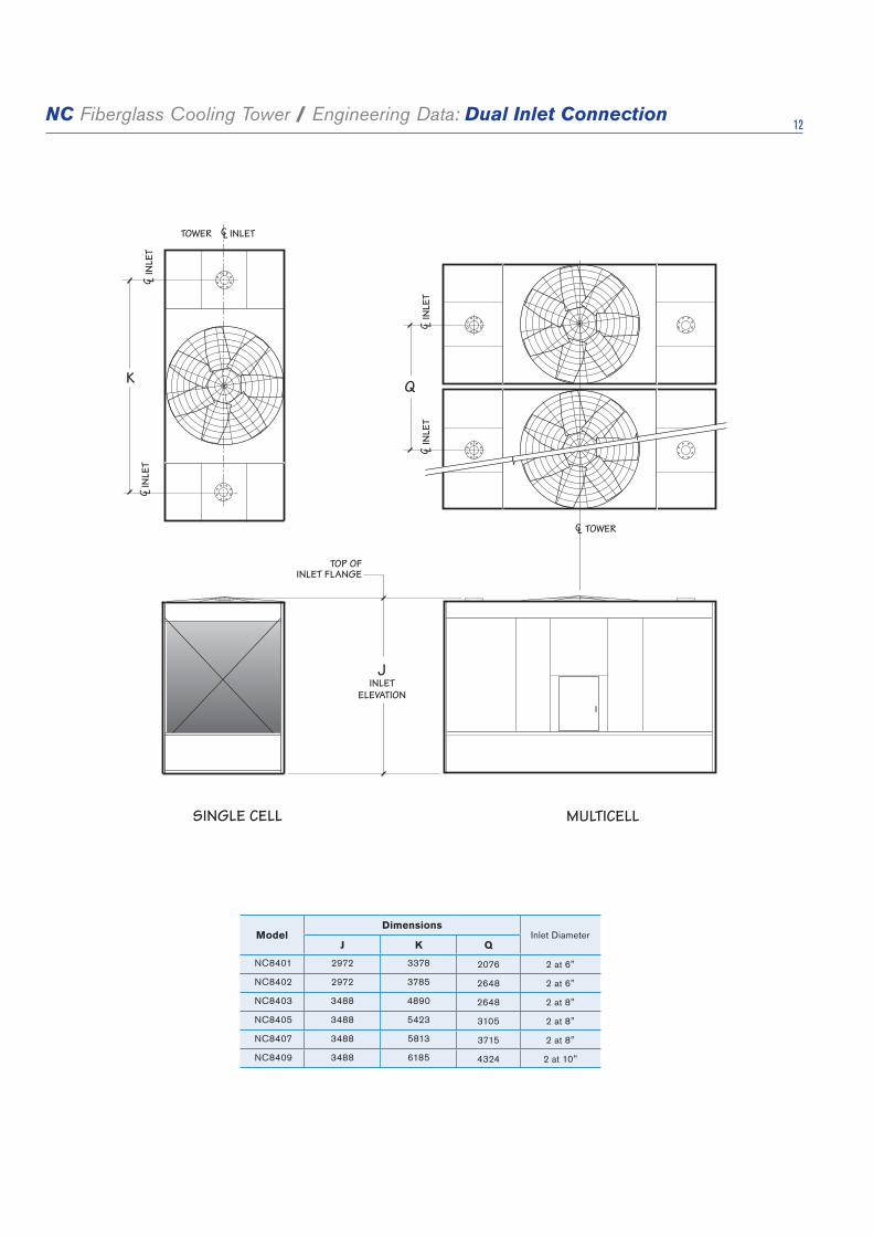
NC Fiberglass Cooling Tower / Engineering Data: Dual Inlet Connection 12
SINGLE CELL MULTICELL
K
CLTOWER INLET
C LIN
LET
C LIN
LET
Q
C LIN
LET
C LIN
LET
JINLET
ELEVATION
CL TOWER
TOP OFINLET FLANGE
ModelDimensions
Inlet DiameterJ K Q
NC8401 2972 3378 2076 2 at 6"
NC8402 2972 3785 2648 2 at 6"
NC8403 3488 4890 2648 2 at 8"
NC8405 3488 5423 3105 2 at 8"
NC8407 3488 5813 3715 2 at 8"
NC8409 3488 6185 4324 2 at 10"

NC Fiberglass Cooling Tower / Engineering Data: Single Inlet Connection 13
D E
CLC L
TOWER
CLTOWERCLINLETCLINLET
TOW
ER C
ELL
FACE OFBOTTOM INLETCONNECTION
TOP OFSUPPORT
SINGLE BOTTOMINLET NOTE 5
SINGLE BOTTOMINLET NOTE 5
162
Model Inlet DiameterD E
NC8401 na na 6"
NC8402 714 610 8"
NC8403 716 737 8"
NC8405 805 921 10"
NC8407 879 1270 10"
NC8409 886 1422 10"
NOTE1 Use this bulletin for preliminary layouts only. Obtain current
drawings from your Marley sales representative.2 All external piping loads, including weight, thrust and lateral loads
of riser and horizontal piping plus the weight of water in the internal riser must be supported independent of the tower. Internal riser adds additional vertical operating loads to external piping at the bottom inlet flange.
3 All piping and supports beyond the inlet connection—and their design—are by others.
4 Allow adequate clearance for entry to tower access doors and safe use of optional ladder. Refer to appropriate Marley drawings.
5 The bottom inlet connects at the tower collection basin floor. Refer to appropriate Marley drawings.
6 Contact your Marley sales representative for the required pump head for single-inlet applications.
7. Weight of internal piping must be added to tower weights. Contact your Marley sales representative for combined tower weight information.
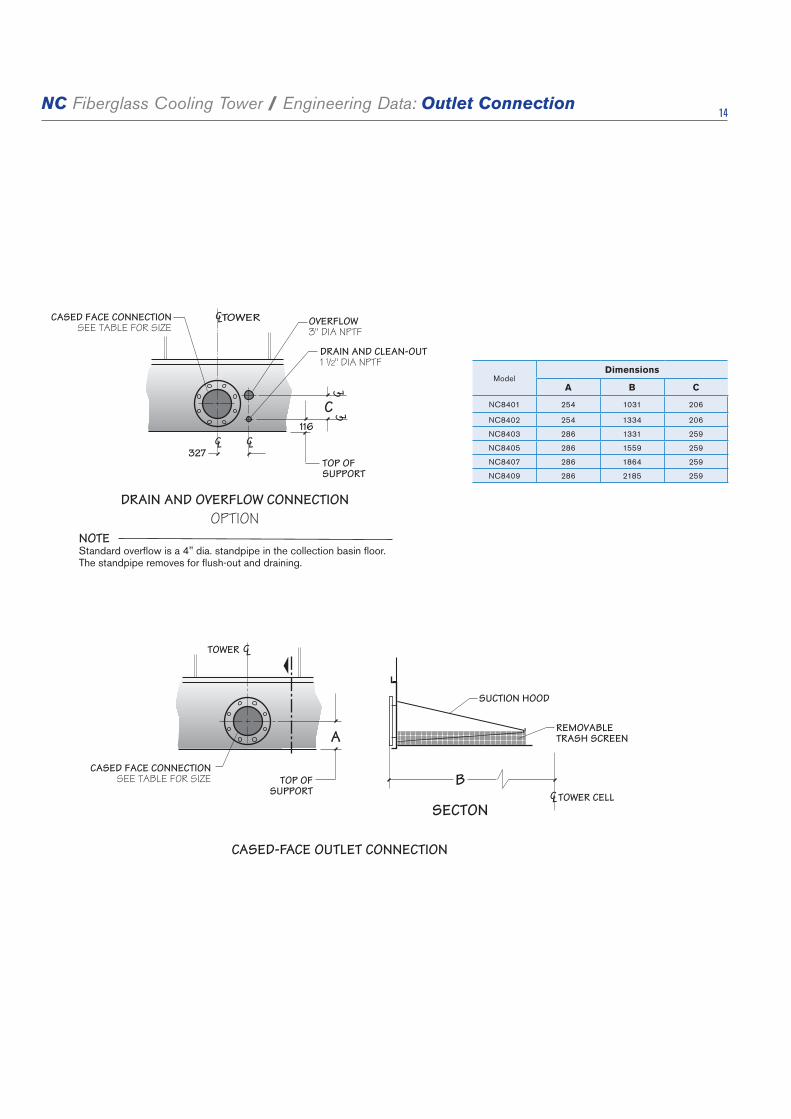
NC Fiberglass Cooling Tower / Engineering Data: Outlet Connection 14
116
327
CLTOWER
CL
OVERFLOW3" DIA NPTF
DRAIN AND CLEAN-OUT1 1/2" DIA NPTF
TOP OFSUPPORT
CL
C LC L
CASED FACE CONNECTIONSEE TABLE FOR SIZE
C
DRAIN AND OVERFLOW CONNECTIONOPTION
CL
CASED FACE CONNECTIONSEE TABLE FOR SIZE TOP OF
SUPPORT
A
TOWER
CLTOWER CELLB
SECTON
SUCTION HOOD
REMOVABLETRASH SCREEN
CASED-FACE OUTLET CONNECTION
NOTEStandard overflow is a 4" dia. standpipe in the collection basin floor. The standpipe removes for flush-out and draining.
ModelDimensions
A B C
NC8401 254 1031 206
NC8402 254 1334 206
NC8403 286 1331 259
NC8405 286 1559 259
NC8407 286 1864 259
NC8409 286 2185 259
DEPRESSED SIDE-OUTLET SUMP CONNECTION

NC Fiberglass Cooling Tower / Engineering Data: Outlet Connection 15
CLSUMP
CLTOWERCELL
SECTION
BOTTOM OFCOLLECTIONBASIN FLOOR TOP OF
SUPPORT
REMOVABLETRASH SCREEN
518
721MIN CLEARANCE
352
803
730
C LO
UTLE
T
35
SUMP OUTLETSEE TABLEFOR SIZE
DEPRESSED SIDE-OUTLET SUMP CONNECTION
BOTTOM OUTLET CONNECTION
TOWER COLLECTIONBASIN FLOOR
OUTLETSEE TABLE FOR SIZE
SECTION
REMOVABLETRASH SCREEN
NOTE BOTTOM OUTLET IS ALSO AVAILABLE WITHOUTTRASH SCREEN
35
TOP OFSUPPORT
BOTTOMOF BASINFLOOR
NOTE• Flowratemaybelimitedbythemaximumflowforunitsize.• Forgravity-flowsituations(astoanindoortank),usebottomoutletordepressedsideoutletsump.Cased-faceoutletisnot
recommended for gravity flow.• Flowlimitsaretheoutletcapacitiesperoutletbasedonthedesignoperatingwaterlevel—216mmabovethetopofsupporton
models NC8401 through NC8405—241mm on NC8407 thru NC8409.
Maximum Flow Per Outlet Diameter m3/hr
Outlet Type Flow Type ModelOutlet Diameter
4" 6" 8" 10" 12" 14" 16" 18" 20" 24"
Bottompump flow w/ anti-vortex plate or gravity
flow w/ or w/o anti-vortex plate
NC8401 thru NC8405 35.6 80.6 143 225.5 320.9 392.7 519 569.9 754.5 912.8
NC8407 thru NC8409 37.9 86.3 152.8 241 342.9 419.7 554.6 718.6 869.7 1112
pump flow w/o anti-vortex plate NC8401 thru NC8409 16.1 36.8 65.2 102.8 146.2 179 236.7 306.4 380.7 552.6
Sumppump flow w/ anti-vortex plate or gravity
flow w/ or w/o anti-vortex plate
NC8401 thru NC8405 204.4 362.3 571.2 812.6 973
NC8407 thru NC8409 204.4 362.3 571.2 812.6 994.6
pump flow w/o anti-vortex plate NC8401 thru NC8409 143 253.5 400 568.9 696.1
Cased-Face Outlet
pump flow onlyNC8401 thru NC8405 204.4 362.3 571.2 812.6
NC8407 thru NC8409 204.4 362.3 571.2 812.6 994.6

NC Fiberglass Cooling Tower / Engineering Data: Support 16C E
C LA
NCH
OR
BOLT
C LC L
AN
CHO
RBO
LTA
NCH
OR
BOLT
C LA
NCH
OR
BOLT
W O
VERA
LL W
IDTH
OF
BASI
N
DCL ANCHOR
BOLTCLANCHOR
BOLT
OVERALL OF BASIN
28 28
A
L
HOLES FOR16mm ANCHORBOLTS 8 REQD
TOWER COLLECTIONBASIN
57
57
SUPPORTING STEELSINGLE CELL
Model
Dimensions Design Operating
Weight/Cellkg
Maximum Design Operating Load
at Anchorkg
W L C D E
NC8401 3912 1988 3798 1932 1104 3547 602
NC8402 4318 2559 4202 2503 1104 4449 739
NC8403 5537 2559 5423 2503 1104 6861 1069
NC8405 6071 3016 5957 2960 1138 8067 1077
NC8407 6401 3626 6287 3570 1202 10648 1429
NC8409 6833 4235 6719 4179 1202 12611 1668
NC Models with Velocity Recovery Cylinder
NC8407 6401 3626 6287 3575 1202 10813 1430
NC8409 6833 4235 6719 4185 1202 12907 1707
1 Use this bulletin for preliminary layouts only. Obtain current drawings from your Marley sales representative for final design.
2 Purchaser to provide tower support complete with holes and anchor bolts. Do not use studs! Anchor points must be framed flush and level at top.
3 Design operating weight occurs with collection basin full to overflow level. Actual operating weight varies with flow and piping scheme.
4 Wind reactions can be calculated by multiplying by p, which is the wind pressure in psf. Seismic reactions can be calculated by design g. Wind loads are additive to operating loads.
NOTE5 Tower may be placed on a flat concrete slab. Side outlet and optional
side drain and overflow must be specified. See pages 14 and 15 and consult your Marley sales representative.
6. Dimensions between anchor bolts may vary depending on the number of cells and options. Dimensions shown are for a standard single cell arrangement. Obtain current drawings from your Marley sales representative for final dimension.
NORMALGAUGE
28
SUPPORTBY OTHERS
TOWERCOLLECTIONBASIN
3
SECTION A

NC Fiberglass Cooling Tower / Engineering Data: Support 17
CONCRETE PIER SUPPORTSINGLE CELL
Model
Dimensions Design Operating
Weight/Cellkg
Maximum Design Operating Load
at Anchorkg
W L C D E
NC8401 3912 1988 3798 1932 1104 3547 602
NC8402 4318 2559 4202 2503 1104 4449 739
NC8403 5537 2559 5423 2503 1104 6861 1069
NC8405 6071 3016 5957 2960 1138 8067 1077
NC8407 6401 3626 6287 3570 1202 10648 1429
NC8409 6833 4235 6719 4179 1202 12611 1668
NC Models with Velocity Recovery Cylinder
NC8407 6401 3626 6287 3575 1202 10813 1430
NC8409 6833 4235 6719 4185 1202 12907 1707
1 Use this bulletin for preliminary layouts only. Obtain current drawings from your Marley sales representative for final design.
2 Tower may be supported from piers at each anchor bolt location, as a support alternative. Piers should be level. Adequate clearance for piping and maintenance must be provided.
3 Design operating weight occurs with collection basin full to overflow level. Actual operating weight varies with flow and piping scheme.
4 Wind reactions can be calculated by multiplying by p, which is the wind pressure in psf. Seismic reactions can be calculated by design g. Wind loads are additive to operating loads.
NOTE5 Tower may be placed on a flat concrete slab. Side outlet and optional
side drain and overflow must be specified. See pages 14 and 15 and consult your Marley sales representative.
6. Dimensions between anchor bolts may vary depending on the number of cells and options. Dimensions shown are for a standard single cell arrangement. Obtain current drawings from your Marley sales representative for final dimension.
7 Pier height is decided by the main outlet pipe diameter and installation elevation.
VIEW B
C EC L
AN
CHO
RBO
LTC L
C LA
NCH
OR
BOLT
AN
CHO
RBO
LTC L
AN
CHO
RBO
LT
W O
VERA
LL W
IDTH
OF
BASI
N
DCL ANCHOR
BOLTCLANCHOR
BOLT
OVERALL OF BASIN
28 28
B
L
HOLES FOR16mm ANCHORBOLTS 8 REQD
TOWER COLLECTIONBASIN
57
150
150
57
HEIGHT

NC Fiberglass Cooling Tower / Engineering Data: Freeze Prevention 18
When the ambient air temperature falls below 0°C, the water in a cooling tower can freeze. Marley Technical Report #H-003 “Operating Cooling Towers in Freezing Weather” describes how to prevent freezing during operation. Available at spxcooling.com or ask your Marley sales representative for a copy.
During shutdown, water collects in the cold water basin and may freeze solid. You can prevent freezing by adding heat to the water left in the tower—or, you can drain the tower and all exposed pipework at shutdown.
Indoor Storage Tank
With this type of system, water flows from an indoor tank, through the load system, and back to the tower, where it is cooled. The cooled water flows by gravity from the tower to the tank located in a heated space. At shutdown, all exposed water drains into the tank, where it is safe from freezing.
The table on page 23 lists typical drain-down capacities for all NC tower models. Although we do not produce tanks, many of our representatives offer tanks supplied by reputable manufacturers.
The amount of water needed to successfully operate the system depends on the tower size and flow and on the volume of water contained in the piping system to and from the tower. You must select a tank large enough to contain those combined volumes—plus a level sufficient to maintain a flooded suction on your pump. Control makeup water according to the level where the tank stabilizes during operation.
NOTEVolumes shown are maximums for the flow ranges indicated. Actual volumes will usually be less. Contact your Marley sales representative for more specific information.
NC Drain-Down Capacity
ModelRange of Tower
Design m3/hr
Drain Down
Maximum LitersModel
Range of Tower
Design GPM
Drain Down
Maximum Liters
NC8401
30-64 1404
NC8405
77-184 3668
66-102 1522 186-279 3941
104-141 1594 282-366 4240
143-177 1673 368-461 4440
179-209 1730 463-570 4584
NC8402
42-86 1923
NC8407
93-227 4997
89-134 2033 229-341 5390
136-182 2150 343-454 5652
184-229 2233 457-568 5837
209-273 2294 570-690 6110
NC8403
65-700 3070
NC8409
109-273 6333
710-159 3320 275-409 6696
236-316 3501 411-545 7105
318-386 3634 547-681 7230
388-480 3819 684-810 7544

Specifications Specification Value
Marley / NC Fiberglass Cooling Tower / Specifications: Base 19
1.0 Base:
1.1 Provide an induced draft, crossflow type, factory assembled, film fill, industrial duty, fiberglass and galvanized steel cooling tower situated as shown on the plans. The limiting overall dimensions of the tower shall be _____ wide, _____ long, and _____ high. Total operating kW of all fans shall not exceed ____ kW, consisting of ___ @ _____ kW motor(s). Tower shall be similar and equal in all respects to Marley Model ____________.
2.0 Thermal Performance and Efficiency:
2.1 The tower shall be capable of cooling _____ m3/hr of water from ____ °C to _____ °C at a design entering air wet-bulb temperature of _____ °C, and its thermal rating shall be Certified by the Cooling Technology Institute.
2.2 The tower shall be capable of a mini-mum _____ m3/hr per kW efficiency per ASHRAE Standard 90.1 and China Efficiency standards.
3.0 Performance Warranty:
3.1 CTI Certification notwithstanding, the cooling tower manufacturer shall guaran-tee that the tower supplied will meet the specified performance conditions when the tower is installed according to plan. If, because of a suspected thermal perfor-mance deficiency, the owner chooses to conduct an on-site thermal performance test under the supervision of a qualified, disinterested third party in accordance with CTI or ASME standards during the first year of operation; and if the tower fails to perform within the limits of test tolerance; then the cooling tower manu-facturer will pay for the cost of the test and will make such corrections as are appropriate and agreeable to the owner to compensate for the performance defi-ciency.
■ Your specification base establishes the type, configuration, base material and physical limitations of the cooling tower to be quoted. During the planning and layout stages of your project, you will have focused your attention on a cool-ing tower selection that fits your space allotment, and whose power usage is acceptable. Limitations on physical size and total operating kilowatts avoid the introduction of unforeseen operational and site-related influences. Specifying the number of cells and the maximum fan kW/cell will work to your advantage. The benefit of crossflow towers is that they are inherently easy to operate, access and maintain. Compared to counterflow towers, crossflow towers have a spacious plenum between banks of fill for easy access to all of the tower’s inter-nal components, plus the water distribution system is adjacent to the fan deck and can be maintained during operation.
■ CTI Certification means that the tower has been tested under operating conditions and found to perform as rated by the manufac-turer under those circumstances. It assures the buyer that the tower is not intentionally or inadvertently undersized by the manufac-turer.
■ The minimum efficiency per ASHRAE Standard 90.1 for induced draft open cooling towers applied to comfort cooling is 8.68 m3/hr per kW @ 35/29.5/23.9. There are no efficiency requirements for non-comfort cooling applications. If you want greater efficiency you can require it by specifying a higher ASHRAE Standard 90.1 m3/hr per kW. Each model's ASHRAE Standard 90.1 rating can be viewed in our online sizing and selection software at spxcooling.com/update.
■ CTI certification alone is not sufficient to assure you that the tower will perform satisfactorily in your situation. Certification is established under relatively con-trolled conditions, and towers seldom operate under such ideal circumstances. They are affected by nearby structures, machinery, enclosures, effluent from other towers, etc. Responsible and knowledgeable bidders will take such site-specific effects into consideration in selecting the tower—but the specifier must insist by the written specification that the designer/manufacturer guarantee this “real world” performance. Any reluctance on the part of the bidder should cause you some concern.

Specifications Specification Value
Marley / NC Fiberglass Cooling Tower / Specifications: Base 20
4.0 Design Loading:
4.1 The tower structure, anchorage and all its components shall be designed by licensed structural engineers per the International Building Code to withstand a wind load of 146.5 kg/m2 psf, as well as a .3g seismic load. The fan deck and hot water basin covers shall be designed for 2.4kPa live load or a 91kg concentrated load. Guardrails, where specified, shall be capable of withstanding a 890N concen-trated live load in any direction, and shall be designed in accordance with OSHA guidelines. Conforms to ISO 14122 Aprt 3 standards 45 kgf.
5.0 Construction:
5.1 Except where otherwise specified, all components of the cooling tower shall be fabricated of fiberglass and heavy-gauge steel, protected against corrosion by Z600 galvanizing or hot dip galvazizing. The tower shall be capable of withstand-ing water having a pH of 6.5 to 8.0; a chloride content (NaCl) up to 300 mg/L; a sulfate content (SO4) up to 250 mg/L; a calcium content (CaCO3) up to 500 mg/L; silica (SiO2) up to 150 mg/L; and design hot water temperatures up to 52°C. The circulating water shall contain no oil, grease, fatty acids or organic sol-vents.
5.2 The specifications, as written, are intend-ed to indicate those materials that will be capable of withstanding the above water quality in continuing service, as well as the loads described in paragraph 4.1. They are to be regarded as minimum requirements. Where component materi-als peculiar to individual tower designs are not specified, the manufacturers shall take the above water quality and load carrying capabilities into account in the selection of their materials of manufac-ture.
■ It is important to understand the distinction between structure and anchor-age. Specifying that only the anchorage meet these requirements means the tower can become non-functional, even fall down, yet remain attached to the foundation. Specifying structure will require the tower to remain operational. The indicated design values are the minimums allowed under accepted design standards. They give you assurance that the tower can be operated in a normal cooling tower environment. Most NC models will withstand significantly higher wind and seismic loads. If your geographic location dictates higher wind load or seismic load values, please make the appropriate changes, after discussion with your Marley sales representative. Some countries and states, like Florida, require structure and anchorage to meet a given loading. Check with your local officials. 146.5 kg/m2 windload, .3g seismic load—applicable for most applications but consult the local code official for actual requirements. 2.4kPa live load, 890N concentrated load—ensures the tower can be safely accessed for routine maintenance when a guardrail is installed as well ensuring the end user complies with government safety laws.
■ In the history of cooling towers, no other coating for carbon steel has exhibited the success and longevity of galvanization in exposure to the normal cooling tower water quality defined at left. No paints, electrostatically-applied coatings or rubberized compounds, however exotic they may be, can approach galvaniza-tion's history of success. Except for those unusual operating situations where the circulating water may be so laden with suspended solids, algae, fatty acids, product fibers, active organisms reflected in BOD, and the like that plugging of the fill is a probability, reasonable attention to the construction materials and/or their coatings is all that is normally required. If extended longevity of the tower is required—or unusually harsh operating conditions are expected—consider specifying stainless steel as either the base construction material, or the material utilized for specific components of your choice. See Stainless Steel Options on page 25.
Specifications Specification Value
Marley / NC Fiberglass Cooling Tower / Specifications: Base 21
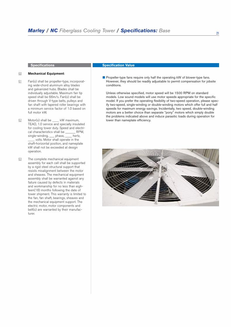
6.0 Mechanical Equipment: 6.1 Fan(s) shall be propeller-type, incorporat-
ing wide-chord aluminum alloy blades and galvanized hubs. Blades shall be individually adjustable. Maximum fan tip speed shall be 66m/s. Fan(s) shall be driven through V-type belts, pulleys and fan shaft with tapered roller bearings with a minimum service factor of 1.0 based on full motor kW.
6.2 Motor(s) shall be ____ kW maximum, TEAO, 1.0 service and specially insulated for cooling tower duty. Speed and electri-cal characteristics shall be ______ RPM, single-winding, ___ phase, ____ hertz, ____ volts. Motor shall operate in the shaft-horizontal position, and nameplate kW shall not be exceeded at design operation.
6.3 The complete mechanical equipment assembly for each cell shall be supported by a rigid steel structural support that resists misalignment between the motor and sheaves. The mechanical equipment assembly shall be warranted against any failure caused by defects in materials and workmanship for no less than eigh-teen(18) months following the date of tower shipment. This warranty is limited to the fan, fan shaft, bearings, sheaves and the mechanical equipment support. The electric motor, motor components and belt(s) are warranted by their manufac-turer.
■ Propeller-type fans require only half the operating kW of blower-type fans. However, they should be readily adjustable to permit compensation for jobsite conditions. Unless otherwise specified, motor speed will be 1500 RPM on standard models. Low sound models will use motor speeds appropriate for the specific model. If you prefer the operating flexibility of two-speed operation, please spec-ify two-speed, single-winding or double-winding motors which offer full and half speeds for maximum energy savings. Incidentally, two speed, double-winding motors are a better choice than separate “pony” motors which simply double the problems indicated above and induce parasitic loads during operation for lower than nameplate efficiency.

Specifications Specification Value
Marley / NC Fiberglass Cooling Tower / Specifications: Base 22
7.0 Fill, Louvers and Drift Eliminators:
7.1 Fill shall be film type, thermoformed of 0.32mm thick PVC, with louvers formed as part of each fill sheet. Fill shall be suspended from hot dip galvanized struc-tural tubing supported from the tower structure, and shall be elevated above the floor of the cold water basin to facilitate cleaning. Air inlet faces of the tower shall be free of water splash-out. Fill shall be capable of withstanding a hot water tem-perature of 52°C.
7.2 Drift eliminators shall be PVC, triple-pass, and shall limit drift losses to 0.005% or less of the design water flow rate.
■ Louvers integral with the fill keep the flowing water within the confines of the fill. The separate external louvers used by others permit water to escape the fill and form ice or produce an unsightly situation adjacent to the tower and waste water. If you plan to use your tower in the wintertime, particularly for free cool-ing, integral louvers will put your operating concerns to rest. Integral louvers offer the best available technology for winter operation and water conservation. Fill options are available for hot water temperatures up to 60°C.
■ Drift rate varies with design water loading and air rate, as well as drift eliminator depth and number of directional changes. A drift rate of 0.001% is readily available on many standard models. If a lower rate is required, please discuss with your Marley sales rep-resentative. Keep in mind…
•Driftfortowerswiththree-pass high effi-ciency eliminators constitute a small per-centage of water usage.
•Unlikethermalperformance,driftratesarenot certified and field drift tests are cost prohibitive for most applications.
•Driftratesbelow0.001aredifficulttomeasureinthe field.
•Certainwatertreatmentchemicalscanimpactthedriftrate.
LOUVERS
DRIFT ELIMINATOR
FILL

Specifications Specification Value
Marley / NC Fiberglass Cooling Tower / Specifications: Base 23
8.0 Hot Water Distribution System:
8.1 Two open basins (one above each bank of fill) shall receive hot water piped to each cell of the tower. Each basin shall be equipped with removable, fiberglass covers capable of withstanding the loads described in paragraph 4.1. The water distribution system shall be accessible and maintainable during tower fan and water operation.
8.2 Each basin shall include at least one cast-iron inlet flange for customer piping connection. Removable, interchangeable polypropylene nozzles installed in the floor of these basins shall provide full coverage of the fill by gravity flow.
9.0 Casing, Fan Deck and Fan Guard:
9.1 The casing and fan deck shall be FRP with steel sub-structure, and shall be capable of withstanding the loads described in paragraph 4.1. The top of the fan cylinder shall be equipped with a conical, non-sagging, removable fan guard, fabricated of welded 8mm and 7 gauge rods, and hot dip galvanized after fabrication. Fan cylinders 1.5m in height and over shall not be required to have a fan guard.
10.0 Access:
10.1 A large fiberglass, rectangular access door shall be located on the cased faces for entry into the cold water basin. Doors shall provide access to the fan plenum area to facilitate inspection and allow maintenance to the fan drive system.
■ Gravity-flow distribution basins are a feature of crossflow type towers, result-ing in operating pump heads of 3 to 6 meters less than that encountered in counterflow towers with pressurized spray systems. Also, these basins are located where they can be easily inspected—even maintained—while the tower is in operation. Some manufacturers require shutting down the tower to clean the distribution system. Can you afford to do that?
■ The access doors on NC8401 and NC8402 towers are 77cm wide by 84cm high. On NC8403 thru NC849 the access doors are 122cm high. Small access doors are prohibitive and dis-courage maintenance, which in turn can impact your operation. Specifying the size of the door will cause some bidders to take exception, alerting you to a potential maintenance headache.

Specifications Specification Value
Marley / NC Fiberglass Cooling Tower / Specifications: Base 24
11.0 Cold Water Collection Basin:
11.1 The collection basin shall be fiberglass supported by a Z600 heavy mill galva-nized or hot dip galvanized structure and shall include the number and type of outlet connections required to accom-modate the out-flow piping system shown on the plans. Outlet connections shall be equipped with debris screens. A fac-tory installed, float operated, mechani-cal make-up valve shall be included. An overflow and drain connection shall be provided in each cell of the cooling tower. The basin floor shall slope toward the drain to allow complete flush out of debris and silt which may accumulate. Towers of more than one cell shall include steel flumes for flow and equalization between cells. The basin shall be accessible and maintainable while water is circulating.
12.0 Scope of Work:
12.1 The cooling tower manufacturer shall be responsible for the design, fabrication, and delivery of materials to the project site and for the erection of the tower over supports provided by others. Unless otherwise specified, all supply and return piping, pumps, controls and electrical wiring will be outside the cooling tower manufacturer's scope of work.
■ The NC tower design offers cased-face outlets, side-outlet sumps and bot-tom outlets to accommodate a significant variety of piping schemes. Unless so specified, the tower you may be asked to approve may only be available with one type of outlet connection, requiring you to redesign your piping layout.
■ Please be clear in your specifications and inquiry documents regarding the full scope of work expected. That will help assure that your bid comparisons will be made on as equal a basis as possible—and will help to avoid any misunder-standings during the execution and implementation of the contracts.

Specifications Specification Value
Marley / NC Fiberglass Cooling Tower / Specifications: Options 25
Stainless Steel
4.1 Replace paragraph 5.1 with the follow-ing: Except where otherwise specified, all components of the cooling tower shall be fabricated of fiberglass and heavy-gauge, series 300 stainless steel. The tower shall be capable of withstanding water having a chloride content (NaCl) up to 750 mg/L; a sulfate content (SO4) up to 1200 mg/L; a calcium content (CaCO3) up to 800 mg/; silica (SiO2) up to 150 mg/L; and design operating ranges up to 10°C. The circulating water shall contain no oil, grease, fatty acids, or organic sol-vents.
Convenience and Safety Options
Guardrail and Ladder:
9.3 Add the following paragraph in the Access section: The top of the tower shall be equipped with a sturdy guardrail, complete with kneerail and toeboard, designed according to ISO 14122 Part 3 standards. Posts, toprails and kneerails shall be 40mm x 25mm rectangular tub-ing. The guardrail assembly shall be hot dipped galvanized and capable of with-standing a 45 kgf concentrated live load in any direction. Posts shall be spaced on centers of 159cm or less. A 46cm wide HDG ladder shall be permanently attached to the endwall casing of the tower, rising from the base of the tower to the top of the guardrail.
Ladder Extension:
10.2 Add the following to the end of the above paragraph: Provide a ladder extension for connection to the foot of the ladder attached to the tower cas-ing. This extension shall be long enough to rise from the roof /grade level to the base of the tower. The installing contractor shall be responsible for cutting the ladder to length; attaching it to the foot of the tower ladder; and anchoring it at its base.
Ladder Safety Cage:
9.3 Add the following paragraph in the Access section: A heavy gauge galva-nized steel safety cage shall surround the ladder, extending from a point approxi-mately 2150mm above the foot of the ladder to the top of the handrail.
■ For pure resistance to corrosion—coupled with the capability to meet stringent fire and building codes—there is no substitute for fiberglass and stainless steel. No paints or electostatically-applied coatings, however exotic they may be, can match stainless steel's ability to withstand adverse operating conditions.
■ The NC cooling tower has been designed to minimize the need for maintenance personnel to get on top of the tower to perform maintenance and inspections. For the comfort and safety of your operating personnel, we recommend that you specify a ladder and guardrail—and that you require it of all bidders! If you prefer a stainless steel guardrail and ladder, replace HDG with S300 stainless steel in the specification.
■ Many towers are installed such that the base of the tower is 61cm or more above the roof or grade level. This makes it difficult to get up to the foot of the attached ladder. The ladder extension alleviates this problem. Marley ladder extensions are available in standard 1.5m and 3.3m lengths.
■ To meet ISO guidelines, towers whose fan decks are 6m or more above roof or grade, and which are equipped with ladders, should have safety cages sur-rounding the ladders, but with approximately 2m clear headroom.
Specifications Specification Value
Marley / NC Fiberglass Cooling Tower / Specifications: Options 26
Additional Ladder
9.2 Replace the following paragraph in the Access section: An HDG ladders shall be permanently attached to each endwall of the tower, rising from the base of the tower to fandeck.
Access Door Ladder
9.2 Replace the following paragraph in the Access section: An HDG ladders shall be permanently attached from the access door to the base of the tower..
Ladder Safety Gate:
10.3 Add the following paragraph in the Access section: A welded galvanized steel, self-closing gate shall be provided at the guardrail level of the ladder.
Plenum Walkway
10.2 Add the following paragraph in the Access section: Provide a factory-installed, walkway extending from one endwall access door to the other endwall. This walkway shall be supported by a steel framework, and the top of the walk-way shall be at or above the cold water overflow level. Walkway and framework to be equivalent material to tower basin structure.
Interior Mechanical Equipment Access Platform
10.2 Add the following paragraph in the Access section: A factory-installed, elevated platform convenient to the care and maintenance of the tower's mechani-cal equipment shall be provided. Walkway and framework to be equivalent material to tower sub-structure.
■ If you prefer a stainless steel ladder, replace HDG with S300 stainless steel in the specification.
■ Ladder extensions are also available with this option. If you prefer a stainless steel ladder, replace HDG with S300 stainless steel in the specification.
■ A galvanized self-closing gate located at the guardrail level of the fan deck. Stainless steel is available with the stainless guardrail option.
■ Provides an elevated walkway within the tower plenum.
■ Provides an elevated walkway within the tower plenum to access the mechani-cal equipment.

Specifications Specification Value
Marley / NC Fiberglass Cooling Tower / Specifications: Options 27
Miscellaneous Options
Sound Control
1.2 Add the following paragraph under Base: The cooling tower shall be quiet operation, and shall produce an overall level of sound not higher than _______ dB(A) measured at _______ m from the locations in the table below. All low noise options and combinations shall be CTI Certified for thermal performance.
Quiet Fan
6.1 Fan(s) shall be propeller-type, incorporat-
ing a minimum of eight wide-chord alu-minum alloy blades and galvanized hubs. Blades shall be individually adjustable. Fan(s) shall be driven through a V-type belts, pulleys, and tapered roller bearings.
Single Hot Water Inlet Connection per Cell:
8.2 Replace this paragraph with the fol-lowing: Each cell of the tower shall include a single hot water inlet connec-tion located below the cold water collec-tion basin. An internal system of piping shall deliver water equally to the distribu-tion basins without the need for balancing valves. This internal piping system shall require no scheduled maintenance, and shall be located such that it does not interfere with normal maintenance access.
Location 63 125 250 500 1000
Discharge
Air Inlet
Cased Face
Location 2000 4000 8000 Overall dB(A)
Discharge
Air Inlet
Cased Face
■ Sound produced by a standard NC Cooling Tower operating in an unobstructed environment will meet all but the most restrictive noise limitations—and will react favorably to natural attenuation. Where the cooling tower has been sized to operate within an enclosure, the enclosure itself will have a damping effect on sound.Soundalsodeclineswithdistance—byabout5or6dB(A)eachtimethedistance doubles. Where noise at a critical point is likely to exceed an accept-able limit, you have several options—listed below in ascending order of cost impact: •Whereonlyaslightreductioninnoisewillsatisfy—andthesourceofconcernis in a particular direction—merely turning the cooling tower may be the answer. Less sound emanates from the cased face of the cooling tower than does from the air intake face. •Inmanycases,noiseconcernsarelimitedtonighttime,whenambientnoiselevels are lower and neighbors are trying to sleep. You can usually resolve these situations by using two-speed motors—operating the fans at reduced speed without cycling “after hours”. The natural nighttime reduction in wet-bulb temperature makes this a very feasible solution in most areas of the world, but the need to avoid cycling may cause the cold water temperature to vary signifi-cantly.
■ The Marley "Quiet Package" includes the affordable Quiet Fan mechanical option, optimized to achieve the lowest possible sound levels while maintaining efficiency.
■ Tip Speed—unlike thermal performance, no certification program exists for sound. While Marley conducts actual sound tests on all its configurations there are only a few ways for the client to ensure they get a quiet tower. •Oneistoconductafieldsoundtestafterinstallation.On-sitetestingafterinstallation can however be inaccurate depending on the environment. •Specifyingfanbladetipspeedisonewaytophysicallyforcethetowerselec-tion to be quiet. Tip speed is easily checked by multiplying the fan rpm by the fancircumferenceatthebladetip(π fandia).Over61m/sisconsideredhighbymost people. 51-61 is considered typical and expected. 41-51 would be con-sidered low noise. Below 41 is difficult to hear above the water noise.
■ This option reduces what might otherwise be a complex hot water piping lay-outtoasimple,singleconnectionpercell.Italsoavoidsanunsightly(perhapsunsafe)mazeofpipeexposedabovethetopdeckofthetower. Bottom inlet piping lends itself to close-spaced, multicell installations and to those situations where it is appropriate to keep all pipework below the level of the tower.
Specifications Specification Value
Marley / NC Fiberglass Cooling Tower / Specifications: Options 28
The internal piping must extend to the tower exterior. Removable, interchange-able polypropylene nozzles installed in the floor of these basins shall provide full coverage of the fill by gravity flow.
0.38mm PVC Fill: 6.1 Replace the following paragraph in the
Fill and Eliminator Section: Fill shall be film type, thermoformed of 0.38 mm thick PVC, with louvers and drift elimina-tors formed as part of each fill sheet. Fill shall be suspended from hot dip galva-nized structural tubing supported from the tower structure, and shall be elevated above the floor of the cold-water basin to facilitate cleaning. Air inlet faces of the tower shall be free of water splash out.
Fan Cylinder Extension: 8.1 Add the following paragraph in the
Casing, Fan Deck and Fan Guard sec-tion: A fiberglass fan cylinder extension shall be provided to elevate the discharge to a height of____________above the existing fan cylinder.
■ Raises the hot water temperature limit to 52°C. Also offers greater UV stability.
■ Extensions may be considered necessary in order to elevate the discharge beyond the bounds of an enclosure. Fan cylinders extensions are available in 1m increments.


UNIT 505, BLOCK BPHILEO DAMANSARA 2NO. 15 JALAN 16/11OFF JALAN DAMANSARA46350 PETALING JAYA, MALAYSIA60 3 7947 [email protected]
In the interest of technological progress, all products are subject to design and/or material change without notice. ©2009 SPX Cooling Technologiessea_NCF-TS-09