marley sigma steel cooling tower engineering data and
TRANSCRIPT
Sigma SteelCOOLI NG TOWE R
E NG I N E E R I NG DATA
AN D S PECI FICATION S

Engineering Data
Schematic 6Support 7Concrete Basin 8Piping 9Environmental 10Energy Management 11
Specifications / Base
Base 12Thermal Performance 13Construction 14Fan Deck and Fan Cylinder 15Mechanical Equipment 15Fill, Louvers and Drift Eliminators 17Hot Water Distribution System 18Casing 18Access 18Cold Water Collection Basin 19Scope of Work 19
Specifications / Options
Control OptionsControl System 20Basin Heater 21Fan Motor Variable Speed Drive 21Marley Premium VFD System 22Vibration Limit Switch 24
Convenience and Safety OptionsStairway 24Plenum Walkway 24Ladder Extension 24Ladder Safety Cage 25Oil Level Sight Glass 25
Miscellaneous OptionsSteel Cold Water Basin 25Hot Water Basin Covers 25Air Inlet Screens 26Low Noise Tower 26Service Life-Relate Customization 27
Sigma Steel — Contents 3

accomplish the specified thermal performance—but which will include normal operation- and maintenance-enhancing accessories and features. It will also incorporate those standard materials which testing and experience has proven to provide best results in normal operating condi-tions.
Pages 20 thru 27 provide some paragraphs intended to add those features, components, and materials that will customize the tower to meet the user's requirements. Space does not permit definition and explanation of all of the possible options that can be applied to the Sigma Steel. SPX Cooling Technologies realizes that you, the purchaser, must be happy with the tower's characteris-tics, and we are prepared to provide—or provide for—any reasonable enhancement that you are willing to define and purchase.
Your needs will become part of the continuing betterment of this Marley product line.
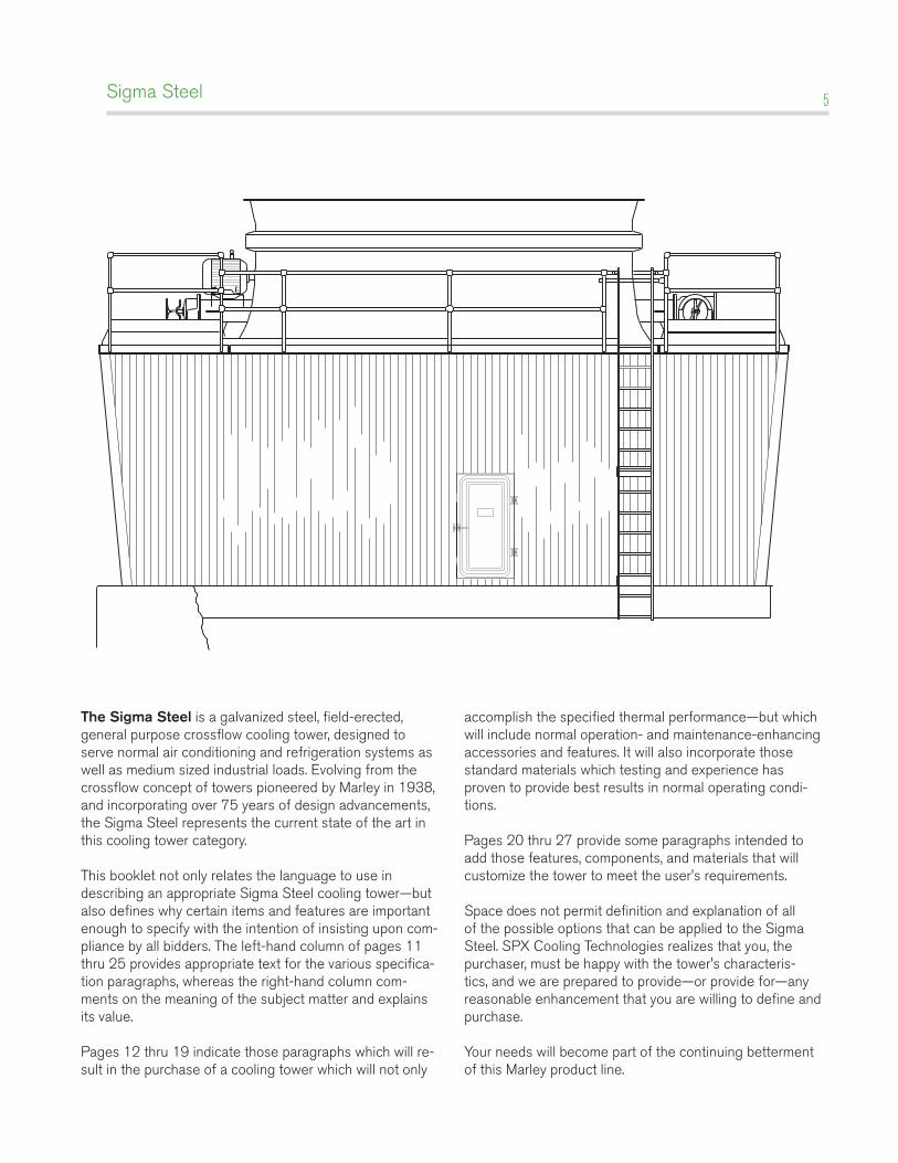
The Sigma Steel is a galvanized steel, field-erected, general purpose crossflow cooling tower, designed to serve normal air conditioning and refrigeration systems as well as medium sized industrial loads. Evolving from the crossflow concept of towers pioneered by Marley in 1938, and incorporating over 75 years of design advancements, the Sigma Steel represents the current state of the art in this cooling tower category. This booklet not only relates the language to use in describing an appropriate Sigma Steel cooling tower—but also defines why certain items and features are important enough to specify with the intention of insisting upon com-pliance by all bidders. The left-hand column of pages 11 thru 25 provides appropriate text for the various specifica-tion paragraphs, whereas the right-hand column com-ments on the meaning of the subject matter and explains its value.
Pages 12 thru 19 indicate those paragraphs which will re-sult in the purchase of a cooling tower which will not only
Sigma Steel 5
Sigma Steel — Engineering Data: Schematic 6
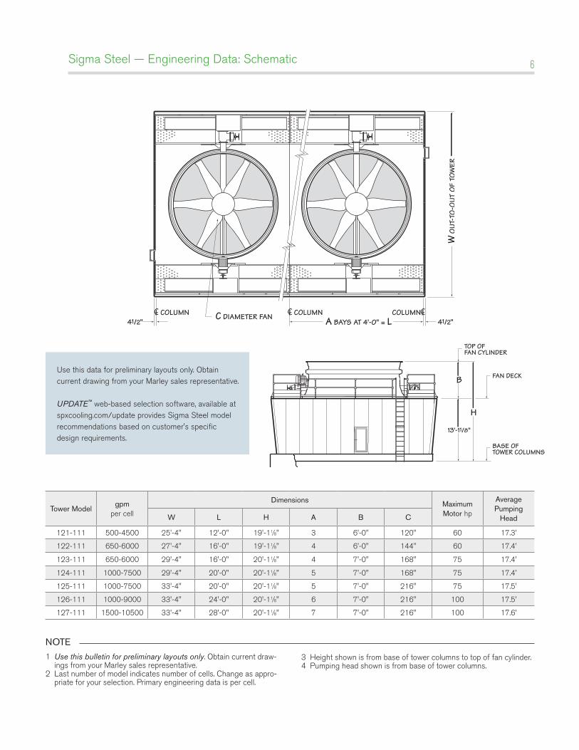
A BAYS AT 4'-0" = LC DIAMETER FAN41/2" 41/2"
COLUMNCOLUMN CLCLCOLUMNCL
W O
UT-T
O-O
UT O
F TO
WER
NOTE
1 Use this bulletin for preliminary layouts only. Obtain current draw-ings from your Marley sales representative.
2 Last number of model indicates number of cells. Change as appro-priate for your selection. Primary engineering data is per cell.
3 Height shown is from base of tower columns to top of fan cylinder.4 Pumping head shown is from base of tower columns.
H
B
TOP OFFAN CYLINDER
BASE OFTOWER COLUMNS
FAN DECK
13'-11/8"
Tower Modelgpm
per cell
Dimensions Maximum Motor hp
Average Pumping
HeadW L H A B C
121-111 500-4500 25'-4" 12'-0" 19'-11⁄8" 3 6'-0" 120" 60 17.3'
122-111 650-6000 27'-4" 16'-0" 19'-11⁄8" 4 6'-0" 144" 60 17.4'
123-111 650-6000 29'-4" 16'-0" 20'-11⁄8" 4 7'-0" 168" 75 17.4'
124-111 1000-7500 29'-4" 20'-0" 20'-11⁄8" 5 7'-0" 168" 75 17.4'
125-111 1000-7500 33'-4" 20'-0" 20'-11⁄8" 5 7'-0" 216" 75 17.5'
126-111 1000-9000 33'-4" 24'-0" 20'-11⁄8" 6 7'-0" 216" 100 17.5'
127-111 1500-10500 33'-4" 28'-0" 20'-11⁄8" 7 7'-0" 216" 100 17.6'
Use this data for preliminary layouts only. Obtain current drawing from your Marley sales representative.
UPDATE™ web-based selection software, available at spxcooling.com/update provides Sigma Steel model recommendations based on customer's specific design requirements.

Sigma Steel — Engineering Data: Support 7
Plan
A SPACES AT 4'-0" = L6"
W O
VERA
LL O
F BA
SIN
SUMP
OVERFLOW
AIR INLET FACE
AIR INLET FACE
CAS
ED E
NDW
ALL
FA
CE
CAS
ED E
NDW
ALL
FA
CE
PRIMARY SUPPORTBEAM
INTERMEDIATEBEAM
NOTE
1 Use this bulletin for preliminary layouts only. Obtain current draw-ings from your Marley sales representative.
2 Steel beams must include 7⁄8" dia. holes to accept anchor bolts provided with tower. Other contractors or purchaser must design and erect supporting steel.
3 Maintain at least 2'-0" of clear space at tower endwalls for construction purposes. Air inlet faces must have unobstructed air supply. If obstructions exist nearby, consult your Marley sales representative.
4 Operating weight is wet weight of tower and steel basin, including 6" of water in the cold water basin.
5 View shown is typical single cell beam arrangement.
1'-6"
6"
RECOMMENDED OPERATING WATER LEVEL
Section
TowerModel
Dimensions Operating Weight lb
A W L Single Fan Cell Each Cell Add
121-111 3 23'-8" 12'-0" 37670 33150
122-111 4 25'-8" 16'-0" 49875 45105
123-111 4 27'-8" 16'-0" 50320 45230
124-111 5 27'-8" 20'-0" 60290 55200
125-111 5 31'-8" 20'-0" 67150 61220
126-111 6 31'-8" 24'-0" 77960 72115
127-111 7 31'-8" 28'-0" 88850 83590
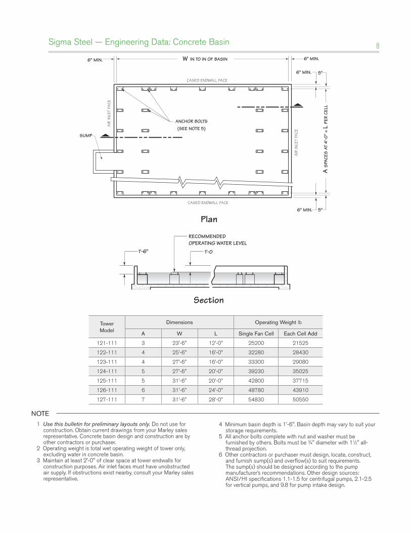
Sigma Steel — Engineering Data: Concrete Basin 8
Plan
6" MIN. 5"
6" MIN. 5"
ANCHOR BOLTS(SEE NOTE 5)
6" MIN. 6" MIN.
A S
PACE
S AT
4'-0
" = L
PER
CEL
L
CASED ENDWALL FACE
CASED ENDWALL FACE
AIR
INLE
T FA
CE
AIR
INLE
T FA
CE
SUMP
W IN TO IN OF BASIN
NOTE
1 Use this bulletin for preliminary layouts only. Do not use for construction. Obtain current drawings from your Marley sales representative. Concrete basin design and construction are by other contractors or purchaser.
2 Operating weight is total wet operating weight of tower only, excluding water in concrete basin.
3 Maintain at least 2'-0" of clear space at tower endwalls for construction purposes. Air inlet faces must have unobstructed air supply. If obstructions exist nearby, consult your Marley sales representative.
4 Minimum basin depth is 1'-6". Basin depth may vary to suit your storage requirements.
5 All anchor bolts complete with nut and washer must be furnished by others. Bolts must be 3⁄4" diameter with 11⁄2" all-thread projection.
6 Other contractors or purchaser must design, locate, construct, and furnish sump(s) and overflow(s) to suit requirements. The sump(s) should be designed according to the pump manufacturer’s recommendations. Other design sources: ANSI/HI specifications 1.1-1.5 for centrifugal pumps, 2.1-2.5 for vertical pumps, and 9.8 for pump intake design.
1'-6" 1'-0
RECOMMENDED OPERATING WATER LEVEL
Section
TowerModel
Dimensions Operating Weight lb
A W L Single Fan Cell Each Cell Add
121-111 3 23'-6" 12'-0" 25200 21525
122-111 4 25'-6" 16'-0" 32280 28430
123-111 4 27'-6" 16'-0" 33300 29080
124-111 5 27'-6" 20'-0" 39230 35025
125-111 5 31'-6" 20'-0" 42800 37715
126-111 6 31'-6" 24'-0" 48780 43910
127-111 7 31'-6" 28'-0" 54830 50550
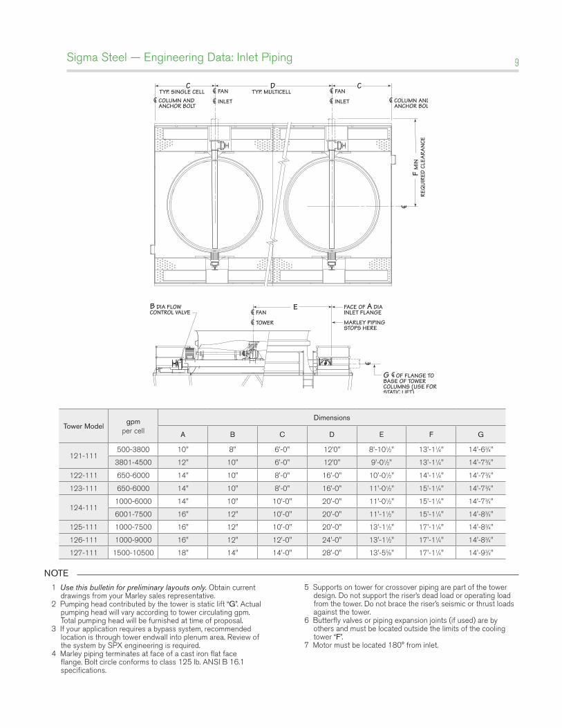
Sigma Steel — Engineering Data: Inlet Piping 9
C C
COLUMN ANDANCHOR BOLT
TYP. SINGLE CELLD
TYP. MULTICELLCL COLUMN AND
ANCHOR BOLTCL
FANCL
INLETCL INLETCL
FANCL
F M
INRE
QUI
RED
CLEA
RAN
CE
C L
E
G C OF FLANGE TOBASE OF TOWERCOLUMNS (USE FORSTATIC LIFT)
FANFACE OF A DIAINLET FLANGE
MARLEY PIPINGSTOPS HERE
B DIA FLOWCONTROL VALVE CL
LC L
TOWERCL
NOTE
1 Use this bulletin for preliminary layouts only. Obtain current drawings from your Marley sales representative.
2 Pumping head contributed by the tower is static lift “G”. Actual pumping head will vary according to tower circulating gpm. Total pumping head will be furnished at time of proposal.
3 If your application requires a bypass system, recommended location is through tower endwall into plenum area. Review of the system by SPX engineering is required.
4 Marley piping terminates at face of a cast iron flat face flange. Bolt circle conforms to class 125 lb. ANSI B 16.1 specifications.
5 Supports on tower for crossover piping are part of the tower design. Do not support the riser’s dead load or operating load from the tower. Do not brace the riser’s seismic or thrust loads against the tower.
6 Butterfly valves or piping expansion joints (if used) are by others and must be located outside the limits of the cooling tower “F”.
7 Motor must be located 180° from inlet.
Tower Modelgpm
per cell
Dimensions
A B C D E F G
121-111500-3800 10" 8" 6'-0" 12'0" 8'-101⁄2" 13'-11⁄4" 14'-63⁄4"
3801-4500 12" 10" 6'-0" 12'0" 9'-01⁄2" 13'-11⁄4" 14'-73⁄4"
122-111 650-6000 14" 10" 8'-0" 16'-0" 10'-01⁄2" 14'-11⁄4" 14'-73⁄4"
123-111 650-6000 14" 10" 8'-0" 16'-0" 11'-01⁄2" 15'-11⁄4" 14'-73⁄4"
124-1111000-6000 14" 10" 10'-0" 20'-0" 11'-01⁄2" 15'-11⁄4" 14'-73⁄4"
6001-7500 16" 12" 10'-0" 20'-0" 11'-11⁄2" 15'-11⁄4" 14'-83⁄4"
125-111 1000-7500 16" 12" 10'-0" 20'-0" 13'-11⁄2" 17'-11⁄4" 14'-83⁄4"
126-111 1000-9000 16" 12" 12'-0" 24'-0" 13'-11⁄2" 17'-11⁄4" 14'-83⁄4"
127-111 1500-10500 18" 14" 14'-0" 28'-0" 13'-55⁄8" 17'-11⁄4" 14'-93⁄4"
Sigma Steel — Engineering Data: Freeze Prevention 10
Sound ConTrol
Sound produced by a Sigma Steel tower operating in an unob-structed environment will meet all but the most restrictive noise limitations—and will react favorably to natural attenuation. Where the tower has been sized to operate within an enclosure, the enclosure itself will have a damping effect on sound. Sound also declines with distance—by about 5 dBA each time the distance doubles. Where noise at a critical point is likely to exceed an acceptable limit, several options are available—listed below in ascending order of cost impact:
• In many cases, noise concerns are limited to nighttime, when ambient noise levels are lower and neighbors are try-ing to sleep. You can usually resolve these situations by us-ing two-speed motors in either 1800/900 or 1800/1200 RPM configuration—operating the fans at reduced speed without cycling “after hours”. The natural nighttime reduc-tion in wet-bulb temperature makes this a very feasible solution in most areas of the world, but the need to avoid cycling may cause the cold water temperature to vary significantly.
• The Marley Variable Frequency Drive automatically mini-mizes the tower’s noise level during periods of reduced load and/or reduced ambient temperature without sacrificing the system’s ability to maintain a constant cold water tem-perature. This is a relatively inexpensive solution, and can pay for itself quickly in reduced energy costs.
• Where noise is a concern at all times—for example, near a hospital—the best solution is to oversize the tower so it can operate continuously at reduced (1200 or 900 RPM) mo-tor speed. Typical sound reductions are 7 dBA at 2/3 fan speed or 10 dBA at half fan speed.
• Extreme cases may require inlet and discharge sound attenuator sections—however, the static pressure loss imposed by attenuators may necessitate an increase in tower size. This is the least desirable approach because of the significant cost impact—and because of the obstruction to normal maintenance procedures.
Your Marley sales representative will help you meet your sound requirements.
EnCloSurES
Occasionally, cooling towers are located inside architectural enclosures for aesthetic reasons. Although Sigma towers adapt well to enclosures, the designer must realize the potential impact of a poorly arranged enclosure on the tower’s performance and operation. The designer must take care to provide generous air inlet paths, and the tower’s fan cylinder discharge height should not be lower than the elevation of the top of the enclosure. Obtain a copy of Marley Technical Report #H-004, “External Influences on Cooling Tower Performance” from your Marley sales represen-tative or on the web at spxcooling.com.
As suggested in the aforementioned Technical Report, it may also be advisable to specify a design wet-bulb temperature 1°F higher than normal to compensate for potential recirculation initi-ated by the enclosure. You’ll benefit from discussing your project with your Marley sales representative.
KEEping iT ClEan
Cooling towers are very effective air washers. Atmospheric dust able to pass through the relatively small louver openings will enter the circulating water system. Increased concentrations can intensify system maintenance by clogging screens and strainers—and smaller particulates can coat system heat transfer surfaces. In areas of low flow velocity—such as the cold water basin—sedi-mentary deposits can provide a breeding ground for bacteria.
In areas prone to dust and sedimentation, you should consider installing some means for keeping the cold water basin clean. Typical devices include side stream filters and a variety of filtration media.
WaTEr TrEaTmEnT
Contaminants including Legionella, an effective consistent water treatment program is required. Controlling blowdown may be adequate in mitigating the potential of corrosion and scale, but biological contamination can only be controlled with biocides.
An acceptable water treatment program must be compatible with the variety of materials incorporated in a cooling tower—ide-ally the pH of the circulating water should fall between 6.5 and 8.0. Batch feeding of chemicals directly into the cooling tower is not a good practice since localized damage to the tower is possible. Specific startup instructions and additional water qual-ity recommendations can be found in the Sigma User Manual which accompanies the tower and also is available from your local Marley sales representative. For complete water treatment recommendations and services, contact your local Marley sales representative.
C a u T i o n
The cooling tower must be located at such distance
and direction to avoid the possibility of contaminated
discharge air being drawn into building fresh air
intake ducts. The purchaser should obtain the
services of a Licensed Professional Engineer or
Registered Architect to certify that the location of
the fluid cooler is in compliance with applicable air
pollution, fire and clean air codes.
Sigma Steel — Engineering Data: Energy Management 11
Cooling towers are usually selected to produce a specific cold water temperature at the higher summertime wet-bulb tem-peratures. During the remainder of the year, the cooling tower is capable of producing much colder water. Unless your system will benefit from the coldest possible water temperature, you should consider controlling cold water temperatures to higher levels. You’ll also save energy by using such control. For greater insight on cold water temperature control, please read “Cooling Tower Energy and its Management”, Technical Report #H-001, available from your Marley sales representative or on the web at spxcooling.com.
Always control leaving water temperature by manipulating the quantity of air that the fan moves through the tower. Varying the quantity of water flow is not normally recommended and can be harmful in freezing weather. You can alternately start and stop single-speed motors to maintain water temperatures within an acceptable range. However, exceeding a total acceleration time of 30 seconds per hour can overheat the motor, causing the insula-tion to fail. Limiting the number of motor starts, on the other hand, can produce significant variations in the temperature of the water delivered to the process.
Increased flexibility can simplify your operating procedures and save you money in the long run, both on operation and on mainte-nance. Here are two of the more popular options.
TWo-SpEEd moTorS
Two-speed motors improve operating flexibility by increasing the number of potential operating modes. Users in northern cli-mates will find that the tower can carry winter loads at half-speed; reducing fan power requirements by 85+% during that time. Two-speed motors also help to control icing during wintertime op-eration. See Marley Technical Report #H-003, “Operating Cooling Towers During Freezing Weather”, available from your Marley sales representative or on the web at spxcooling.com.
Normally, two-speed motors are provided in 1800/900 RPM, single winding configuration, which is the least expensive two-speed option. They are also available in other combinations includ-ing the more expensive double winding.
VariablE SpEEd Fan driVE
Frequency modulation devices work well on induced draft, pro-peller fan cooling towers such as the Sigma Steel cooling tower. However, their design must include the capability to lock out any critical fan speeds and the very low fan speed ranges.
Marley VFD drive systems are designed to combine absolute temperature control with ideal energy management. The cool-ing tower user selects a cold water temperature and the drive system will vary the fan speed to maintain that temperature. Precise temperature control is accomplished with far less stress to the mechanical equipment components. The improved energy management provides fast payback. Indeed, many utilities offer generous rebates for users having installed VFD drives.
Specifications Specification Value
Sigma Steel — Specifications: Base 12
1.0 base:
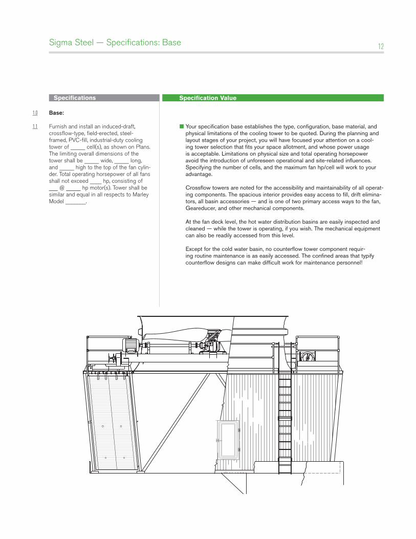
1.1 Furnish and install an induced-draft, crossflow-type, field-erected, steel-framed, PVC-fill, industrial-duty cooling tower of _____ cell(s), as shown on Plans. The limiting overall dimensions of the tower shall be _____ wide, _____ long, and _____ high to the top of the fan cylin-der. Total operating horsepower of all fans shall not exceed ____ hp, consisting of ___ @ _____ hp motor(s). Tower shall be similar and equal in all respects to Marley Model _______.
■ Your specification base establishes the type, configuration, base material, and physical limitations of the cooling tower to be quoted. During the planning and layout stages of your project, you will have focused your attention on a cool-ing tower selection that fits your space allotment, and whose power usage is acceptable. Limitations on physical size and total operating horsepower avoid the introduction of unforeseen operational and site-related influences. Specifying the number of cells, and the maximum fan hp/cell will work to your advantage. Crossflow towers are noted for the accessibility and maintainability of all operat-ing components. The spacious interior provides easy access to fill, drift elimina-tors, all basin accessories — and is one of two primary access ways to the fan, Geareducer, and other mechanical components. At the fan deck level, the hot water distribution basins are easily inspected and cleaned — while the tower is operating, if you wish. The mechanical equipment can also be readily accessed from this level. Except for the cold water basin, no counterflow tower component requir-ing routine maintenance is as easily accessed. The confined areas that typify counterflow designs can make difficult work for maintenance personnel!
Specifications Specification Value
Sigma Steel — Specifications: Base 13
2.0 Thermal performance:
2.1 The tower shall be capable of cooling _____ gpm of water from ____ °F to _____ °F at a design entering air wet-bulb temperature of _____ °F. The cooling tower manufacturer shall guarantee that the tower supplied will meet the specified performance conditions when the tower is installed according to plans.
2.2 The purchaser will arrange for an on-site thermal performance test, to be conduct-ed in the presence of the manufacturer and owner, and under the supervision of a qualified, disinterested third party in accordance with CTI (Cooling Technology Institute) ATC-105 standards during the first full year of operation. If the tower fails to perform within the limits of test tolerance, then the cooling tower manu-facturer will install additional cells and/or make such corrections as are agreeable to the owner and shall pay for the cost of a retest. If the tower still fails to per-form as specified, then the manufacturer shall make such reimbursements as are appropriate and agreeable to the owner to compensate for the performance defi-ciency.
■ Your reason for purchasing a cooling tower is to obtain a continuing flow of cooled water as defined in the first paragraph at left. If the tower that you pur-chase is incapable of performing as specified, then you will not have received full value for your money. Bear in mind that the size—and cost—of a cooling tower varies directly with its true thermal capability. This paragraph is intended to protect you against either intentional or inadvertent under sizing of the tower by the manufacturer. Judging the level of performance of a cooling tower on critical processes is never easy, and the potential risk of a non-performing cooling tower usually causes the requirement for a mandatory acceptance test to be very desirable. Your contract with the successful bidder should establish the acceptable rem-edies for missed performance, which might include: • The addition of one or more cells of tower, as necessary, to bring the cool-
ing tower to the specified level of performance. This is usually limited to the scope of work as defined in the specs, which means that you (the owner) will have to pay for the additional basin, wiring, starters, piping, etc.
• The reimbursement of a portion of the total contract price equal to the percent-age deficiency in performance.
Under no circumstances should you allow the manufacturer to re-pitch the fans to increase motor brake horsepower above that shown in the proposal. That cre-ates additional operating costs that will continue for the life of the tower—and imposes no penalty on the manufacturer.
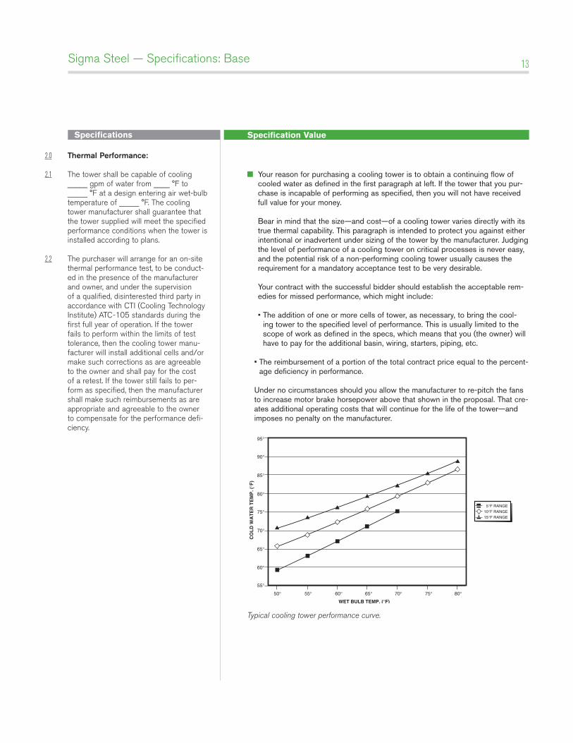
Typical cooling tower performance curve.
55°
50° 55° 60° 65° 70° 75° 80°
5°F RANGE10°F RANGE15°F RANGE
60°
65°
70°
75°
CO
LD
WA
TE
R T
EM
P. (
°F)
WET BULB TEMP. (°F)
80°
85°
90°
95°
Specifications Specification Value
Sigma Steel — Specifications: Base 14
3.0 Construction:
3.1 The tower shall be capable of withstand-ing water having a pH of 6.5 to 8.0; a chloride content (NaCl) up to 300 ppm; a sulfate content (SO4) up to 250 ppm; a calcium content (CaCO3) up to 500 ppm; silica (SiO2) up to 150 ppm; and design hot water temperatures up to 120°F. The circulating water shall contain no oil, grease, fatty acids, or organic solvents.
3.2 The structural framework of the tower, as well as all basins and decking, shall be of heavy gauge cold-formed steel and/or mill shapes, hot-dip galvanized after fabrication to a deposition of at least 2.25 ounces of zinc per square foot.
3.3 Column lines shall be on no greater than 4'-0" longitudinal centers, and the base of all columns shall be firmly anchored. Basic design criteria shall be 30 psf wind load and 5% g seismic load. Framing joints shall be made with 1/2" diameter and larger Series 300 stainless steel machine bolts, nuts and washers.
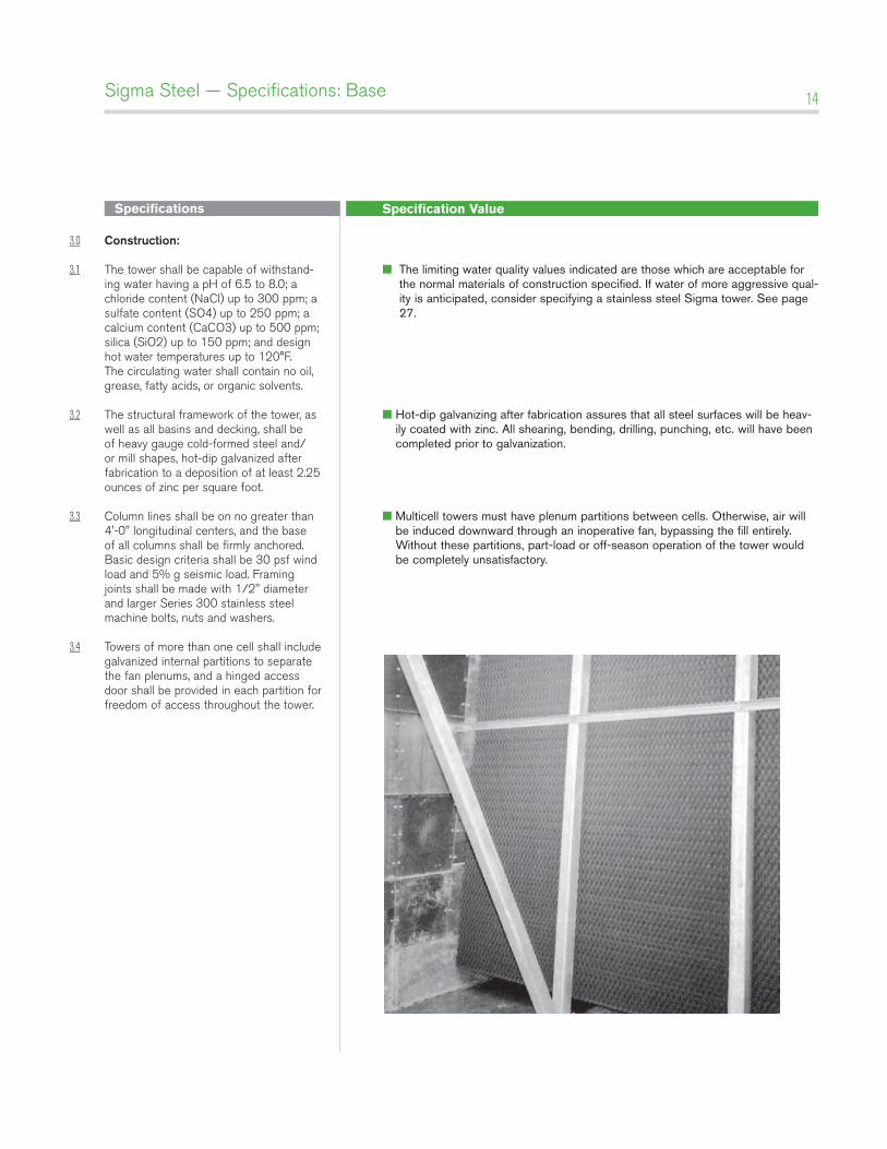
3.4 Towers of more than one cell shall include galvanized internal partitions to separate the fan plenums, and a hinged access door shall be provided in each partition for freedom of access throughout the tower.
■ The limiting water quality values indicated are those which are acceptable for the normal materials of construction specified. If water of more aggressive qual-ity is anticipated, consider specifying a stainless steel Sigma tower. See page 27.
■ Hot-dip galvanizing after fabrication assures that all steel surfaces will be heav-ily coated with zinc. All shearing, bending, drilling, punching, etc. will have been completed prior to galvanization.
■ Multicell towers must have plenum partitions between cells. Otherwise, air will be induced downward through an inoperative fan, bypassing the fill entirely. Without these partitions, part-load or off-season operation of the tower would be completely unsatisfactory.
Specifications Specification Value
Sigma Steel — Specifications: Base 15
4.0 Fan deck and Fan Cylinder:
4.1 The fan deck shall act as a working plat-form for maintenance personnel. It shall be fabricated of no less than 12 gauge steel, and shall be designed for a uniform live load of 60 psf.
4.2 Fan cylinders shall be molded FRP. They shall be through-bolted to the fan deck structure to provide a consistently stable operating shroud for the fan.
5.0 mechanical Equipment:
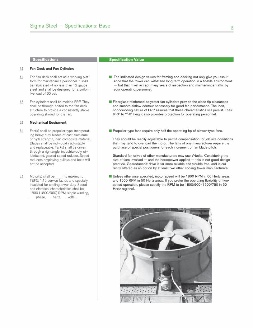
5.1 Fan(s) shall be propeller-type, incorporat-ing heavy duty blades of cast aluminum or high strength, inert composite material. Blades shall be individually adjustable and replaceable. Fan(s) shall be driven through a rightangle, industrial-duty, oil-lubricated, geared speed reducer. Speed reducers employing pulleys and belts will not be accepted.
5.2 Motor(s) shall be ____ hp maximum, TEFC, 1.15 service factor, and specially insulated for cooling tower duty. Speed and electrical characteristics shall be 1800 (1800/900) RPM, single winding, ___ phase, ___ hertz, ___ volts.
■ The indicated design values for framing and decking not only give you assur-ance that the tower can withstand long term operation in a hostile environment — but that it will accept many years of inspection and maintenance traffic by your operating personnel.
■ Fiberglass-reinforced polyester fan cylinders provide the close tip clearances and smooth airflow contour necessary for good fan performance. The inert, noncorroding nature of FRP assures that these characteristics will persist. Their 6'-0" to 7'-0" height also provides protection for operating personnel.
■ Propeller-type fans require only half the operating hp of blower-type fans. They should be readily adjustable to permit compensation for job site conditions that may tend to overload the motor. The fans of one manufacturer require the purchase of special positioners for each increment of fan blade pitch. Standard fan drives of other manufacturers may use V-belts. Considering the size of fans involved — and the horsepower applied — this is not good design practice. Geareducer® drive is far more reliable and trouble free, and is cur-rently offered as an option by at least two other cooling tower manufacturers.
■ Unless otherwise specified, motor speed will be 1800 RPM in 60 Hertz areas and 1500 RPM in 50 Hertz areas. If you prefer the operating flexibility of two-speed operation, please specify the RPM to be 1800/900 (1500/750 in 50 Hertz regions).
Specifications Specification Value
Sigma Steel — Specifications: Base 16
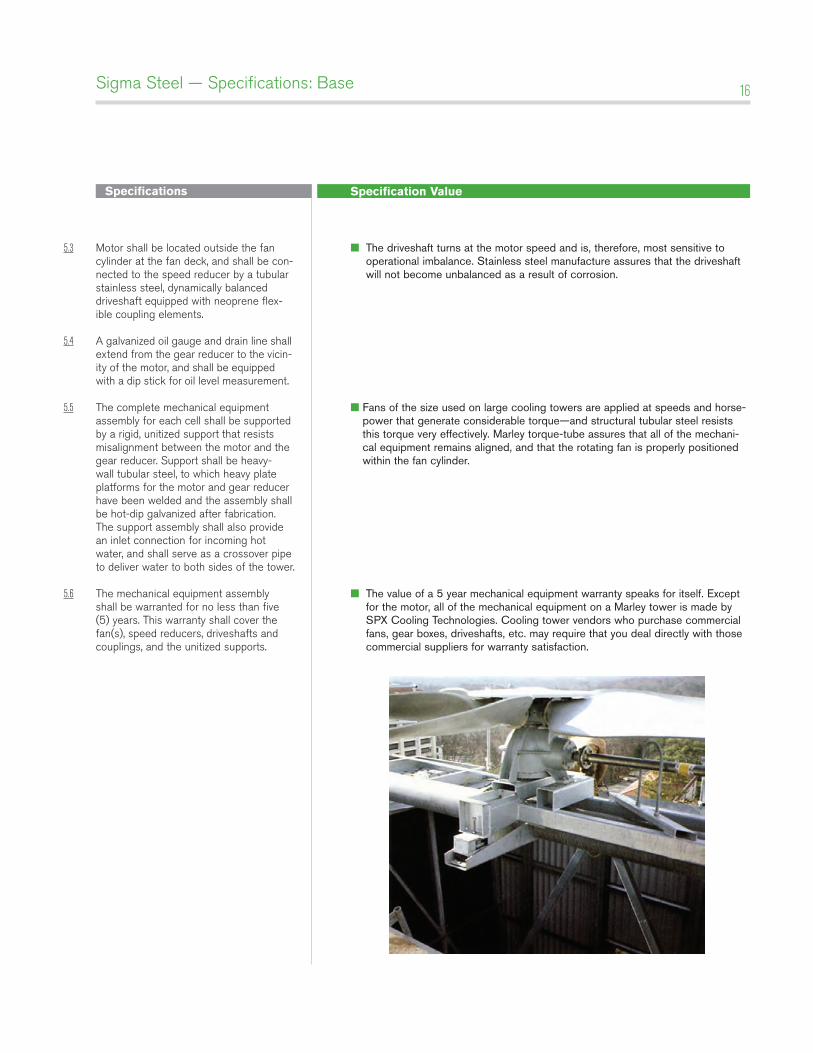
5.3 Motor shall be located outside the fan cylinder at the fan deck, and shall be con-nected to the speed reducer by a tubular stainless steel, dynamically balanced driveshaft equipped with neoprene flex-ible coupling elements.
5.4 A galvanized oil gauge and drain line shall extend from the gear reducer to the vicin-ity of the motor, and shall be equipped with a dip stick for oil level measurement.
5.5 The complete mechanical equipment
assembly for each cell shall be supported by a rigid, unitized support that resists misalignment between the motor and the gear reducer. Support shall be heavy-wall tubular steel, to which heavy plate platforms for the motor and gear reducer have been welded and the assembly shall be hot-dip galvanized after fabrication. The support assembly shall also provide an inlet connection for incoming hot water, and shall serve as a crossover pipe to deliver water to both sides of the tower.
5.6 The mechanical equipment assembly shall be warranted for no less than five (5) years. This warranty shall cover the fan(s), speed reducers, driveshafts and couplings, and the unitized supports.
■ The driveshaft turns at the motor speed and is, therefore, most sensitive to operational imbalance. Stainless steel manufacture assures that the driveshaft will not become unbalanced as a result of corrosion.
■ Fans of the size used on large cooling towers are applied at speeds and horse-power that generate considerable torque—and structural tubular steel resists this torque very effectively. Marley torque-tube assures that all of the mechani-cal equipment remains aligned, and that the rotating fan is properly positioned within the fan cylinder.
■ The value of a 5 year mechanical equipment warranty speaks for itself. Except for the motor, all of the mechanical equipment on a Marley tower is made by SPX Cooling Technologies. Cooling tower vendors who purchase commercial fans, gear boxes, driveshafts, etc. may require that you deal directly with those commercial suppliers for warranty satisfaction.
Specifications Specification Value
Sigma Steel — Specifications: Base 17
6.0 Fill, louvers and drift Eliminators:
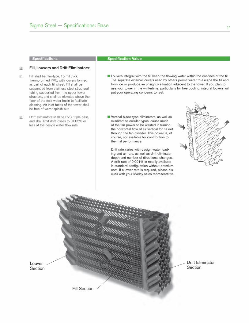
6.1 Fill shall be film-type, 15 mil thick, thermoformed PVC, with louvers formed as part of each fill sheet. Fill shall be suspended from stainless steel structural tubing supported from the upper tower structure, and shall be elevated above the floor of the cold water basin to facilitate cleaning. Air inlet faces of the tower shall be free of water splash-out.
6.2 Drift eliminators shall be PVC, triple-pass, and shall limit drift losses to 0.005% or less of the design water flow rate.
■ Louvers integral with the fill keep the flowing water within the confines of the fill. The separate external louvers used by others permit water to escape the fill and form ice or produce an unsightly situation adjacent to the tower. If you plan to use your tower in the wintertime, particularly for free cooling, integral louvers will put your operating concerns to rest.
��■ Vertical blade-type eliminators, as well as misdirected cellular types, cause much of the fan power to be wasted in turning the horizontal flow of air vertical for its exit through the fan cylinder. This power is, of course, not available for contribution to thermal performance. Drift rate varies with design water load-ing and air rate, as well as drift eliminator depth and number of directional changes. A drift rate of 0.001% is readily available in standard configuration without premium cost. If a lower rate is required, please dis-cuss with your Marley sales representative.
LouverSection
Drift EliminatorSection
Fill Section
Specifications Specification Value
Sigma Steel — Specifications: Base 18
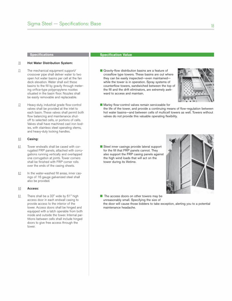
7.0 Hot Water distribution System:
7.1 The mechanical equipment support/crossover pipe shall deliver water to two open hot water basins per cell at the fan deck elevation. Water shall exit these basins to the fill by gravity through meter-ing orifice-type polypropylene nozzles situated in the basin floor. Nozzles shall be easily removable and replaceable.
7.2 Heavy-duty, industrial grade flow-control valves shall be provided at the inlet to each basin. These valves shall permit both flow balancing and maintenance shut-off to selected cells, or portions of cells. Valves shall have machined cast iron bod-ies, with stainless steel operating stems, and heavy-duty locking handles.
8.0 Casing:
8.1 Tower endwalls shall be cased with cor-rugated FRP panels, attached with corru-gations running vertically and overlapped one corrugation at joints. Tower corners shall be finished with FRP corner rolls over the ends of the casing sheets.
8.2 In the water-washed fill areas, inner cas-ings of 16 gauge galvanized steel shall also be provided.
9.0 access:
9.1 There shall be a 33" wide by 61" high access door in each endwall casing to provide access to the interior of the tower. Access doors shall be hinged and equipped with a latch operable from both inside and outside the tower. Internal par-titions between cells shall include hinged doors to give free access through the tower.
■ Gravity-flow distribution basins are a feature of crossflow type towers. These basins are out where they can be easily inspected—even maintained—while the tower is in operation. Spray systems of counterflow towers, sandwiched between the top of the fill and the drift eliminators, are extremely awk-ward to access and maintain.
��■ Marley flow-control valves remain serviceable for the life of the tower, and provide a continuing means of flow-regulation between hot water basins—and between cells of multicell towers as well. Towers without valves do not provide this valuable operating flexibility.
��■ Steel inner casings provide lateral support for the fill that FRP panels cannot. They also support the FRP casing panels against the high wind loads that will act on the tower during its lifetime.
■ The access doors on other towers may be unreasonably small. Specifying the size of the door will cause those bidders to take exception, alerting you to a potential maintenance headache.
Specifications Specification Value
Sigma Steel — Specifications: Base 19
9.2 The top of the tower shall be equipped with a sturdy 42" high guardrail system, complete with top rails, intermediate rails and toeboards, conforming to OSHA standards. Guardrails and posts shall con-sist of 1.66" OD x 15 gauge galvanized structural tubing. Posts shall be spaced on centers of 8'-0" or less.
9.3 One endwall of the tower shall be equipped with a 20" wide aluminum verti-cal ladder, through-bolted to the endwall structure. Ladder shall rise from the cold water basin level to the top of the fan deck guardrail, and shall be designed and installed in conformance with OSHA stan-dards.
10.0 Cold Water Collection basin:
10.1 The cold water collection basin shall be of poured-in-place concrete, provided under the General Contractor's scope of work. The concrete basin design shall be based upon certified loads and dimensions pro-vided by the cooling tower manufacturer
11.0 Scope of Work:
11.1 The cooling tower manufacturer shall be responsible for the design, fabrication, and delivery of materials to the project site, and for the erection of the tower over supports provided by others. Unless otherwise specified, all external piping, pumps, controls, and electrical wiring will be outside the cooling tower manufac-turer's scope of work.
■ Good maintenance practice requires periodic access to the top of the tower to inspect the distribution basins, as well as the structural integrity of the fan deck, fan cylinder, and fan — especially the fan blade securing hardware. There are no induced-draft cooling tower designs that are immune to this need!
■ For the comfort and safety of your operating personnel, the Sigma Steel tower includes a lad-der and guardrail of the quality and design indicated — and we strongly recommend that you require it of all bidders! Portable ladders and other "make-do" access means are inappropri-ate for equipment of this size and complexity.
■� This basic specification assumes that the tower will be erected over a concrete basin at grade level. If the tower is to be installed on an elevated supporting platform, the steel cold water collection basin indicated on page 25 should be included in the specifications.
■ Please be clear in your specifications and inquiry documents regarding the full scope of work expected. That will help assure that your bid comparisons will be made on as equal a basis as possible—and will help to avoid any misunderstandings during the execution and implementation of the contract.
Specifications Specification Value
Sigma Steel — Specifications: Options 20
Control Options
Control System:
5.7: Add the following paragraph in the Mechanical Equipment section: Each cell of the cooling tower shall be equipped with a UL listed control system in a NEMA 3R or 4X outdoor enclosure capa-ble of controlling single-speed or two-speed motors as required, and designed specifically for cooling tower applications. The panel shall include a main fused dis-connect with an external operating han-dle, lockable in the off position for safety. Across-the-line magnetic starters or solid state soft-start starters as required shall be controlled with a thermostatic or solid state temperature controller. Door mount-ed selector switches shall be provided to enable automatic or manual control and wired for 120VAC control. Control circuit to be wired out to terminal blocks for field connection to a remote vibration switch and for access to extra 120VAC 50VA control power, overload trip alarms and remote temperature control devices. The temperature controller shall be adjustable for the required cold water temperature. If a thermostatic controller is used it shall be mounted on the side of the tower with the temperature sensing bulb installed in the cold water basin using a suspension mounting bracket. If a solid state tem-perature controller is used the controller will be door mounted on the control panel. The temperature controller will display two temperatures, one for outgoing water and the other for set point. Water tem-perature input shall be obtained using a three-wire RTD with dry well in the outlet water piping and wired back to the solid state temperature controller in the control panel.
■ If it is your opinion that the control system for the cooling tower should be part of the tower manufacturer’s responsibility, we are in wholehearted agreement with you. Who better to determine the most efficient mode and manner of a tower’s operation—and to apply a system most compatible with it—than the designer and manufacturer of the cooling tower?
Specifications Specification Value
Sigma Steel — Specifications: Options 21
basin Heaters:
10.2 Add the following paragraph in the Cold Water Basin section: Provide a system of electric immersion heaters and con-trols for each cell of the tower to prevent freezing of water in the collection basin during periods of shutdown. The system shall consist of one or more stainless steel electric immersion heaters installed in the basin. A NEMA 4 enclosure shall house a magnetic contactor to energize heaters; a transformer to provide 24 volt control circuit power; and a solid state cir-cuit board for temperature and low water cutoff. A control probe shall be located in the basin to monitor water level and tem-perature. The system shall be capable of maintaining 40°F water temperature at an ambient air temperature of __ °F.
Fan motor Variable Speed drive:
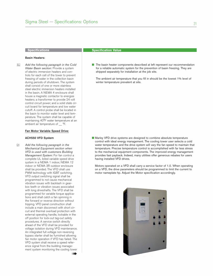
aCH550 VFd System
6.4 Add the following paragraph in the Mechanical Equipment section when VFD is used with customers Building Management System: For fan control a complete UL listed variable speed drive system in a NEMA 1 indoor, NEMA 12 indoor or NEMA 3R outdoor enclosure shall be provided. The VFD shall use PWM technology with IGBT switching. VFD output switching signal shall be programmed to not cause mechanical vibration issues with backlash in gear-box teeth or vibration issues associated with long driveshafts. The VFD shall be programmed for variable torque applica-tions and shall catch a fan spinning in the forward or reverse direction without tripping. VFD panel construction shall include a main disconnect with short cir-cuit and thermal overload protection with external operating handle, lockable in the off position for lock-out tag-out safety procedures. A service switch directly ahead of the VFD shall be provided for voltage isolation during VFD maintenance. An integrated full voltage non-reversing bypass starter shall be furnished allowing fan motor operation if VFD has failed. The VFD system shall receive a speed refer-ence signal from the building manage-ment system monitoring the cooling tower
■ The basin heater components described at left represent our recommendation for a reliable automatic system for the prevention of basin freezing. They are shipped separately for installation at the job site. The ambient air temperature that you fill in should be the lowest 1% level of winter temperature prevalent at site.
■ Marley VFD drive systems are designed to combine absolute temperature control with ideal energy management. The cooling tower user selects a cold water temperature and the drive system will vary the fan speed to maintain that temperature. Precise temperature control is accomplished with far less stress to the mechanical equipment components. The improved energy management provides fast payback. Indeed, many utilities offer generous rebates for users having installed VFD drives. Motors operated on a VFD shall carry a service factor of 1.0. When operating on a VFD, the drive parameters should be programmed to limit the current to motor nameplate hp. Adjust the Motor specification accordingly.
➠
Specifications Specification Value
Sigma Steel — Specifications: Options 22
cold-water temperature. As an option to receiving the speed reference signal from a building management system, the drive must have the capability to receive a 4-20 mA temperature signal from an RTD transmitter. When using an RTD for temperature monitoring and speed control the VFD shall have an internal PI regula-tor to modulate fan speed maintaining set point temperature. The drive’s panel shall display the set-point temperature and cold-water temperature on two separate lines. The bypass shall include a complete electromechanical magnetic bypass cir-cuit with the capability to isolate the VFD when in the bypass mode. Transfer to the bypass mode shall be manual in the event of VFD failure. Once the motor is trans-ferred to the bypass circuit the fan motor will run at constant full speed. Operator controls shall be mounted on the front of the enclosure and shall consist of Start and Stop control, Bypass/VFD selec-tion, Auto/Manual selections and manual speed control. To prevent heating prob-lems in the fan motor the VFD system shall de energize the motor once 25% motor speed is reached and cooling is no longer required. The manufacturer shall supply VFD start-up assistance by a certi-fied technician.
marley premium VFd System
6.4 Add the following paragraph in the Mechanical Equipment section when VFD is used as a stand alone system: For fan control a complete UL listed vari-able speed drive system in a NEMA 12 indoor or NEMA 3R outdoor enclosure shall be provided. The VFD shall use PWM technology with IGBT switching. VFD output switching signal shall be programmed as not to cause mechanical vibration issues with back lash in gear-box teeth or vibration issues associated with long drive shafts. VFD shall be pro-grammed for variable torque application. The VFD shall catch a fan spinning in the forward or reverse direction without trip-ping. VFD panel construction shall include a main disconnect with short circuit and thermal overload protection with external operating handle, lockable in the off posi-tion for lock-out tag-out safety proce-dures. A service switch directly ahead of the VFD shall be provided for voltage iso-
Specifications Specification Value
Sigma Steel — Specifications: Options 23
lation during VFD maintenance. An inte-grated full voltage non-reversing bypass starter shall be furnished allowing fan motor operation if VFD has failed. In the event of a system fault the VFD program logic shall evaluate type of fault determin-ing if safe to automatically transfer fan motor to the bypass starter. Automatic bypass with an earth ground condition shall not be allowed. Once in bypass mode the internal controls will continue to monitor cold water temperature and cycle the fan motor on and off maintain-ing cold-water set point temperature. The drive system shall be designed and oper-ated as a stand-alone system without the need for a BMS system. Operator con-trols shall be mounted on the front of the enclosure and shall consist of Start and Stop control, Bypass/VFD selector switch, Auto/Manual selector switch, Manual speed control, and solid-state tempera-ture controller. An emergency bypass starter selector switch internal to the panel allowing the fan motor to be run at full speed shall be furnished. The system shall include a solid state PI temperature controller to adjust frequency output of the drive in response to the tower cold-water temperature. A four-wire RTD with dry well shall be furnished with the VFD and field installed into the cold-water dis-charge pipe. The temperature of the cold-water and set point shall be displayed on the door of the control panel. The bypass starter shall be integrated into the same enclosure as the VFD including complete circuitry to isolate the VFD when in the bypass mode. To prevent heating prob-lems in the fan motor the VFD system shall de-energize the motor once 25% motor speed is reached and cooling is no longer required. The VFD shall include deicing logic and manual control with the ability to reverse fan rotation includ-ing auto canceling with adjustable time. Speed in deice mode shall not exceed 50% motor speed. The manufacturer shall supply VFD start-up assistance by a certi-fied technician.
Specifications Specification Value
Sigma Steel — Specifications: Options 24
Vibration limit Switch:
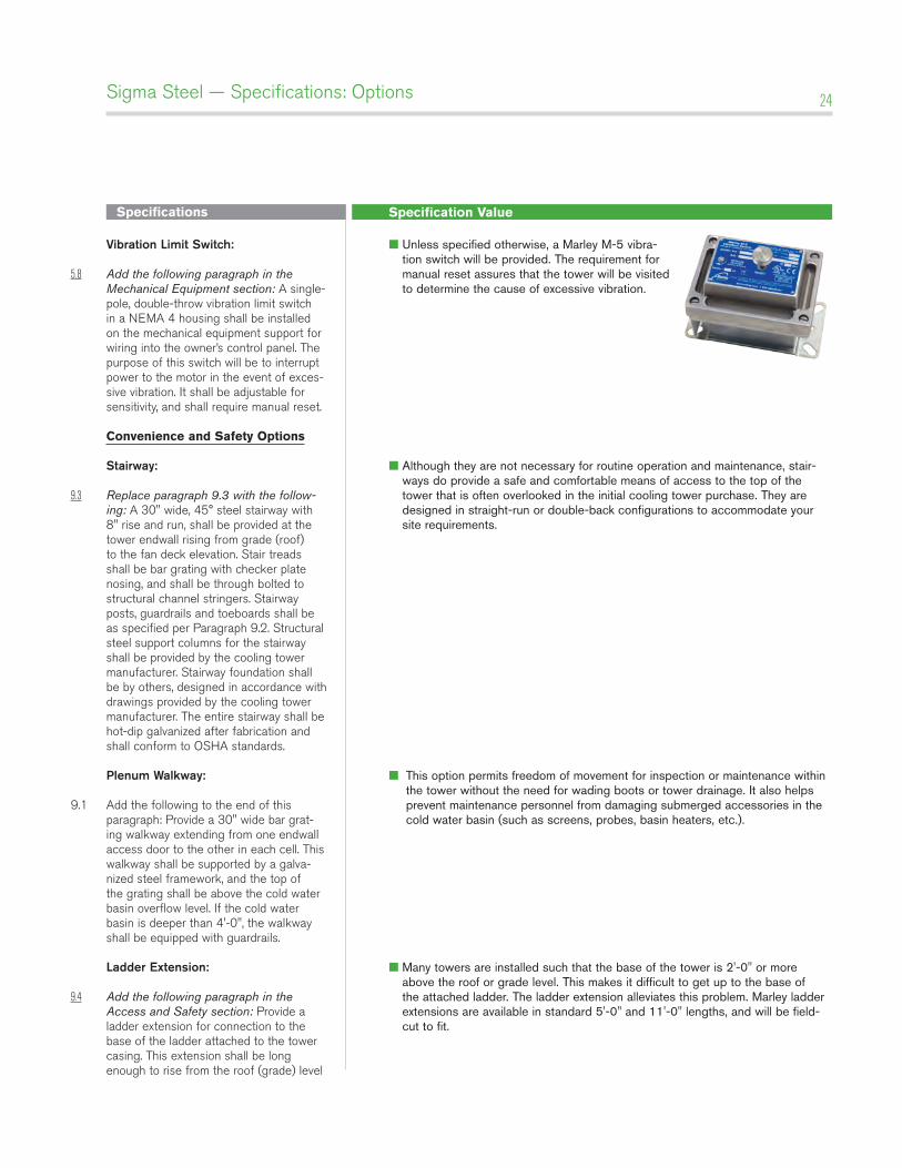
5.8 Add the following paragraph in the Mechanical Equipment section: A single-pole, double-throw vibration limit switch in a NEMA 4 housing shall be installed on the mechanical equipment support for wiring into the owner’s control panel. The purpose of this switch will be to interrupt power to the motor in the event of exces-sive vibration. It shall be adjustable for sensitivity, and shall require manual reset.
Convenience and Safety Options
Stairway:
9.3 Replace paragraph 9.3 with the follow-ing: A 30" wide, 45° steel stairway with 8" rise and run, shall be provided at the tower endwall rising from grade (roof) to the fan deck elevation. Stair treads shall be bar grating with checker plate nosing, and shall be through bolted to structural channel stringers. Stairway posts, guardrails and toeboards shall be as specified per Paragraph 9.2. Structural steel support columns for the stairway shall be provided by the cooling tower manufacturer. Stairway foundation shall be by others, designed in accordance with drawings provided by the cooling tower manufacturer. The entire stairway shall be hot-dip galvanized after fabrication and shall conform to OSHA standards.
plenum Walkway:
9.1 Add the following to the end of this paragraph: Provide a 30" wide bar grat-ing walkway extending from one endwall access door to the other in each cell. This walkway shall be supported by a galva-nized steel framework, and the top of the grating shall be above the cold water basin overflow level. If the cold water basin is deeper than 4'-0", the walkway shall be equipped with guardrails.
ladder Extension:
9.4 Add the following paragraph in the Access and Safety section: Provide a ladder extension for connection to the base of the ladder attached to the tower casing. This extension shall be long enough to rise from the roof (grade) level
■ Unless specified otherwise, a Marley M-5 vibra-tion switch will be provided. The requirement for manual reset assures that the tower will be visited to determine the cause of excessive vibration.
■ Although they are not necessary for routine operation and maintenance, stair-ways do provide a safe and comfortable means of access to the top of the tower that is often overlooked in the initial cooling tower purchase. They are designed in straight-run or double-back configurations to accommodate your site requirements.
■ This option permits freedom of movement for inspection or maintenance within the tower without the need for wading boots or tower drainage. It also helps prevent maintenance personnel from damaging submerged accessories in the cold water basin (such as screens, probes, basin heaters, etc.).
■ Many towers are installed such that the base of the tower is 2'-0" or more above the roof or grade level. This makes it difficult to get up to the base of the attached ladder. The ladder extension alleviates this problem. Marley ladder extensions are available in standard 5'-0" and 11'-0" lengths, and will be field-cut to fit.
Specifications Specification Value
Sigma Steel — Specifications: Options 25
to the base of the tower. Anchorage and lateral bracing of the ladder extension shall be by others.
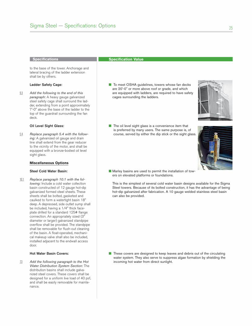
ladder Safety Cage:
9.3 Add the following to the end of this paragraph: A heavy gauge galvanized steel safety cage shall surround the lad-der, extending from a point approximately 7'-0" above the base of the ladder to the top of the guardrail surrounding the fan deck.
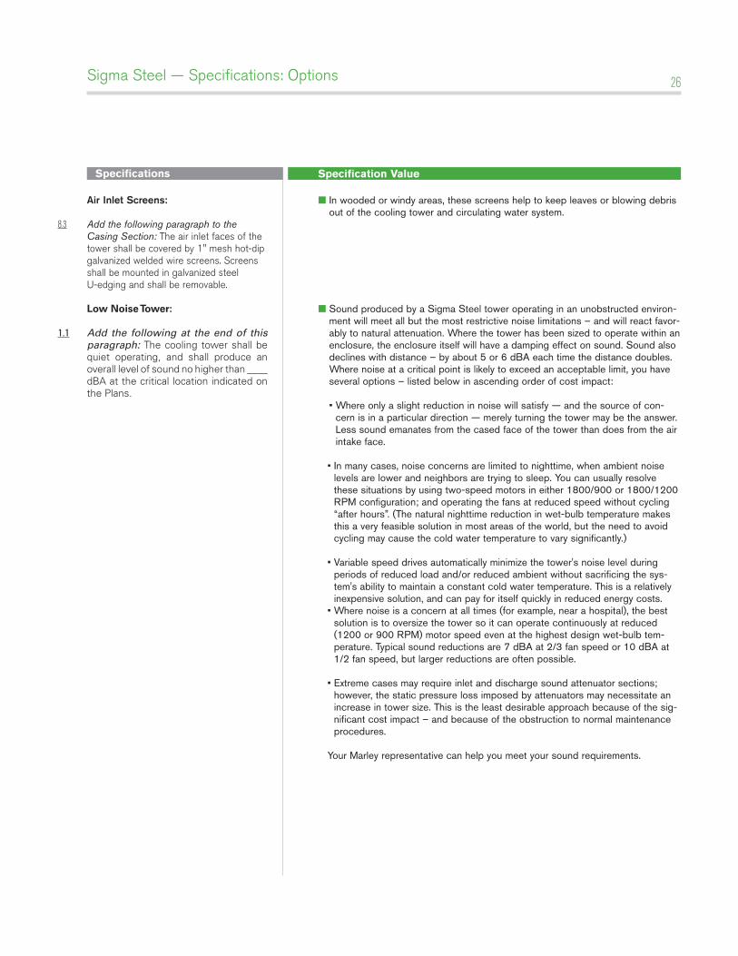
oil level Sight glass:
5.4 Replace paragraph 5.4 with the follow-ing: A galvanized oil gauge and drain line shall extend from the gear reducer to the vicinity of the motor, and shall be equipped with a bronze-bodied oil level sight glass.
Miscellaneous Options
Steel Cold Water basin:
10.1 Replace paragraph 10.1 with the fol-lowing: Include a cold water collection basin constructed of 12 gauge hot-dip galvanized formed steel sheets. These sheets shall be bolted, gasketed and caulked to form a watertight basin 18" deep. A depressed, side outlet sump shall be included, having a 1/4" thick face-plate drilled for a standard 125# flange connection. An appropriately sized (3" diameter or larger) galvanized standpipe overflow shall be provided. The standpipe shall be removable for flush-out cleaning of the basin. A float-operated, mechani-cal makeup valve shall also be included, installed adjacent to the endwall access door.
Hot Water basin Covers: 7.3 Add the following paragraph to the Hot
Water Distribution System Section: The distribution basins shall include galva-nized steel covers. These covers shall be designed for a uniform live load of 40 psf, and shall be easily removable for mainte-nance.
■ To meet OSHA guidelines, towers whose fan decks are 20'-0" or more above roof or grade, and which are equipped with ladders, are required to have safety cages surrounding the ladders.
■ The oil level sight glass is a convenience item that is preferred by many users. The same purpose is, of course, served by either the dip stick or the sight glass.
■ Marley basins are used to permit the installation of tow-ers on elevated platforms or foundations. This is the simplest of several cold water basin designs available for the Sigma Steel towers. Because of its bolted construction, it has the advantage of being hot-dip galvanized after fabrication. A 10 gauge welded stainless steel basin can also be provided.
■ These covers are designed to keep leaves and debris out of the circulating water system. They also serve to suppress algae formation by shielding the incoming hot water from direct sunlight.
Specifications Specification Value
Sigma Steel — Specifications: Options 26
air inlet Screens: 8.3 Add the following paragraph to the
Casing Section: The air inlet faces of the tower shall be covered by 1" mesh hot-dip galvanized welded wire screens. Screens shall be mounted in galvanized steel U-edging and shall be removable.
Low Noise Tower:
1.1 Add the following at the end of this paragraph: The cooling tower shall be quiet operating, and shall produce an overall level of sound no higher than ____ dBA at the critical location indicated on the Plans.
■ In wooded or windy areas, these screens help to keep leaves or blowing debris out of the cooling tower and circulating water system.
■ Sound produced by a Sigma Steel tower operating in an unobstructed environ-ment will meet all but the most restrictive noise limitations – and will react favor-ably to natural attenuation. Where the tower has been sized to operate within an enclosure, the enclosure itself will have a damping effect on sound. Sound also declines with distance – by about 5 or 6 dBA each time the distance doubles. Where noise at a critical point is likely to exceed an acceptable limit, you have several options – listed below in ascending order of cost impact: • Where only a slight reduction in noise will satisfy — and the source of con-
cern is in a particular direction — merely turning the tower may be the answer. Less sound emanates from the cased face of the tower than does from the air intake face.
• In many cases, noise concerns are limited to nighttime, when ambient noise levels are lower and neighbors are trying to sleep. You can usually resolve these situations by using two-speed motors in either 1800/900 or 1800/1200 RPM configuration; and operating the fans at reduced speed without cycling “after hours”. (The natural nighttime reduction in wet-bulb temperature makes this a very feasible solution in most areas of the world, but the need to avoid cycling may cause the cold water temperature to vary significantly.)
• Variable speed drives automatically minimize the tower's noise level during periods of reduced load and/or reduced ambient without sacrificing the sys-tem's ability to maintain a constant cold water temperature. This is a relatively inexpensive solution, and can pay for itself quickly in reduced energy costs.
• Where noise is a concern at all times (for example, near a hospital), the best solution is to oversize the tower so it can operate continuously at reduced (1200 or 900 RPM) motor speed even at the highest design wet-bulb tem-perature. Typical sound reductions are 7 dBA at 2/3 fan speed or 10 dBA at 1/2 fan speed, but larger reductions are often possible.
• Extreme cases may require inlet and discharge sound attenuator sections; however, the static pressure loss imposed by attenuators may necessitate an increase in tower size. This is the least desirable approach because of the sig-nificant cost impact – and because of the obstruction to normal maintenance procedures.
Your Marley representative can help you meet your sound requirements.
Specifications Specification Value
Sigma Steel — Specifications: Options 27
Service life-related Customization: ■ Some adverse water conditions, unsatisfactory air quality, and/or processes that produce corrosive contaminants, may dictate the use of stainless steel for mate-rials of construction in the tower. Refer to our Stainless Steel Sigma Series, in which the use of stainless steel has been maximized. Except for valve bodies and Geareducer, every steel com-ponent of that product line is manufactured of stainless steel. If your project has a need for the extended service life that premium materials will offer, please obtain a copy of "Marley Sigma Stainless Steel Cooling Tower Specifications" from your local Marley sales representative, and extract from it those paragraphs that make sense for you.
Sigma Steel cooling tower
E NG I N E E R I NG DATA AN D
S PECI FICATION S
S PX COOLI NG TECH NOLOG I E S, I NC.
7401 WEST 129 STREET
OVERLAND PARK, KANSAS 66213 USA
P: 913 664 7400
F: 913 664 7439
spxcooling.com
In the interest of technological progress, all products are subject to design and/or material change without notice
ISSUED 06/2013 SSIG-TS-13
COPYRIGHT © 2013 SPX Corporation