market for kr iron - minnesota legislature
TRANSCRIPT

JOHN E. BRYNILDSON, P.E. CONSULTANT
April 11, 1986
Mr. Ron Visness Manager Material Development DNR-Minerals 500 Lafayette Road St. Paul, Minnesota 55146
Dear Mr. Visness:
~~ Brynildson and
.______~-+-' Associates
1489 WEST low A AVENUE
ST. PAUL, MINNESOTA55108 612-641-0676
I am submitting this report entitled "The Current and Future Status of the ADI Industry as a Potential Market for KR Iron". I have described some of the history of ADI's development, current applications, process controls necessary to product it, and some future possibilities. Producers, heat treaters, and ancillary technical people were interviewed about their role in ADI and what their projections for the future were.
I also surveyed them about the desirability of KR Iron as a possible low manganese charge material and plotted demand curves from that data. Demand curves based on selling price are included.
The last part of the report is a brief account of the 2nd ADI Conference in Ann Arbor, Michigan, which I attended in March, 1986. The complete proceeding will be published shortly and will be available for your reviewal.
Thank you for the opportunity to work on such an exciting project. If I can be of any service again please call me.
Sincerely yours,
0 ~ £. £P.-- .d t7 /} rf ~J~E. John E. Brynildson, P.E.
Consultant's Report prepared r993~he Natural Resources Dept 0 Contract Total $8,ooo period 3/7-4/~-
METALLURGICAL SERVICES. PROCESS EVALUATION. MATERIAL SELECTION. FAILURE ANALYSIS • TECHNICAL TRAINING
This document is made available electronically by the Minnesota Legislative Reference Library as part of an ongoing digital archiving project. http://www.leg.state.mn.us/lrl/lrl.asp (Funding for document digitization was provided, in part, by a grant from the Minnesota Historical & Cultural Heritage Program.)

TABLE OF CONTENTS
THE CURRENT AND FUTURE STATUS OF THE ADI INDUSTRY
AS A POTENTIAL MARKET FOR KR IRON
PART I: Section A: ADI Industry: Past, Present, Future
Section B: ADI In-Plant Production Requirements
Section C: Present and Potential Applications of ADI
Section D: Advantages and Possible Disadvantages of ADI vs. Competing Materials
Section E: Potential ADI Market Growth
Section F: The Suitability of KR Iron for Producing ADI
PART II: KR Iron and ADI Survey Results
PART III: Report on 2nd ADI Conference
METALLURGICAL SERVICES• PROCESS EVALUATION• MATERIAL SELECTION• FAILURE ANALYSlS •TECHNICAL TRAINING

THE CURRENT AND FUTURE STATUS OF THE ADI INDUSTRY
AS A POTENTIAL MARKET FOR KR IRON
Prepared By
John E. Brynildson, P.E. Consultant
For Minnesota
Department Of Natural Resources Minerals Division
April 11, 1986
METALLURGICAL SERVICES• PROCESS EVALUATION• MATERIAL SELECTION• FAILURE ANALYSIS• TECHNICAL TRAINING

PART I - Section A
ADI INDUSTRY, PAST, PRESENT, FUTURE
The earliest practical development of Austempered Ductile Iron (ADI) was done in the 1950s. The
International Harvester Company began a search for an alternative material to cast steel track shoes.
This was done under a contract with the U.S. Army. By 1955, International Harvester had
formulated an austempering process to produce ADI track shoes weighing almost 60 pounds. This
early development lost its support and it wasn't until 1976 when General Motors announced large
scale use of ADI in its ring and pinion gears used in the differentials of their rear wheel driven
passenger vehicles. This drew widespread interest to ADI which lead to other applications such as
large gears, rail car wheels, and crankshafts.
Greater impetus was given to the growth of ADI by involvement of companies like
Kymmene-Stroember of Finland, Metallgesellschaft Ag of West Germany, Amax Corporation of
the United States, and others. Companies with potential applications began serious evaluation of
ADI; companies such as Caterpillar Tractor Co., Deere & Company, Ford Motor Company, J.I.
Case, Chrysler Corporation, and others. Once the necessary criteria was established for producing
the base iron in the foundry,. the next hurdle was finding heat treaters with the expertise and
capabilities of performing the austempering treatment. Many, if not all, heat treaters have
austempered steel for many years. Problems arose when the same methods and attitudes were
applied to ductile iron. The process is quite similar but the products of transformation are totally
different. When steel is austempered, the austenite transforms to ferrite and carbides. When
ductile iron is austempered, the high silicon and high carbon cause the austenite to transform to
acicular ferrite and carbon rich austenite which is stable at room temperature. This transformation
is the first stage of two possible stages. If left at the austempering temperature for two short a time
complete Stage I transformation may not occur. Therefore some martensite could form which
would reduce the impact and fracture toughness properties of the ADI. If left too long, the Stage I
transformation products of acicular ferrite and carbon rich austenite will begin to transform to ferrite
and carbides which have an embrittling effect. This condition in tum leads to poor fatigue life and
low fracture toughness. It was due to this special behavior of ADI that many otherwise very
competent heat treaters could not perform successfully.
Presently nine heat treating facilities austemper ADI. One is in Norristown, PA, one is in Livonia,
MI, one is in Elk Grove Village, IL, one in Philadelphia, PA, one in Meadville, PA, one in St.
Louis, MO, one is in Wichita, KS, and two are in Minneapolis, MN. The heat treat facility in
Norristown, PA uses hot oil as the austempering bath while the rest use salt. There are at least
twenty foundries in the United States which are producing ADI base iron on a production or
experimental basis with more interest developing every day. Ongoing research programs such as
Professor Rundman's at Michigan Technological University in Houghton, Professor Carl Loper's
METALLURGICAL SERVICES• PROCESS EVALUATION• MATERIAL SELECTION• FAILURE ANALYSIS• TECHNICAL TRAINING

ADI Industry, Past, Present, Future Page2
at the University of Wisconsin- Madison, the ASME-Gear Research Institute's three-year study and
many "grass roots" R&D programs are revealing more positive aspects of ADI continually.
Once the foundries who want to produce ADI accept the more restrictive chemistry and processing
conditions there will be a very rapid growth of ADI base iron capabilities. The major bottleneck in
the near future could be not having the heat treat capacity to perform the austempering. There is
sufficient capacity at this time ( 40000 tons per year heat treating capacity by some experts
estimates, with 16000 tons to be produced in the foundries during 1986.) It is predicted that 1987
will see 32000 tons of ADI produced which is still within the capacity available. However, after
1987 there could be a shortfall in capacity unless more austempering furnaces are installed. There
is presently research going on which may alleviate part of the potential problem of limited heat treat
facilities. An alloyed ductile iron Ni-Mo-Cu (Nickel-Molybdenum-Copper) could be subjected to
controlled cooling during shakeout to approximate the condition experienced during austempering.
Energy could be saved because this procedure would occur during the cooling down from
solidification. This is still very experimental and would be a solution only for those ADI castings
which did not require machining beforehand.
There is another consideration in sourcing ADI castings; the capabilities of the machining facilities
near the heat treater are important. Due to the work-hardening characteristics of the carbon rich
austenite phase in ADl's microstructure, castings are difficult to machine after the austempering
treatment. Some producers and users of ADI have reported minimal machining problems with
single point tooling (such as a lathe) but multiple cutter tooling such as end or facing mills and
boring and reaming tools cause this work hardening which prohibits machining ease. It naturally
causes dimensional problems also. So for future growth to continue in the application and use of
ADI, close coordination between the user, the foundry, the machining facility and the heat treater
must be further nurtured. With cooperation this problem may be overcome in the future.
A tentative specification for the production of ADI has been submitted to the appropriate committees
of the American Society for Testing and Materials (ASTM) for reviewal. When a specification is in
place growth will accelerate. It will then be easier for the user, foundry, machine shop, and heat
treater to establish procedures and guidelines.
There was a concern raised at the first International Symposium of ADI held in April, 1984 that the
process requirements for the foundry and heat treater would be too stringent. The consensus from
the second International Symposium on ADI held in March, 1986 was that ADI base iron is being
produced and there are heat treaters who can austemper it. There is no doubt as more applications
are uncovered and specifications are established the projected growth could appear conservative.
METALLURGICAL SERVICES• PROCESS EVALUATION• MATERIAL SELECTION• FAILURE ANALYSIS• TECHNICAL TRAINING

PART I - Section B IN-PLANT PRODUCTION REQUffiEMENTS
In order to produce acceptable ADI there needs to be strict adherence to process controls. Two
processors must follow proper procedures: the foundry and the heat treater. It is necessary to
explain the heat treatment of ADI and the base iron requirements in order to understand the process
and material controls needed in the foundry operation.
Austempering consists of heating a ductile iron casting to an appropriate austentizing temperature
(1550°F - 1650°F) followed by a rapid quench into a medium (oil or molten salt) which is
maintained at a temperature in the bainitic transformation range (475°F - 725°F). It is then held in
the austempering bath for a time long enough for transformation to occur. The transformation
which takes place during the austempering of ductile iron is unlike that which occurs during
austempering of steel. In steel, the austenite which has formed at 1650°F undergoes a
transformation in the austempering bath. The austenite phase transforms to ferrite and fine carbides
to form bainite. The products of transformation in ADI are different.
The austenite phase of ADI heat treatment transforms to acicular ferrite and carbon rich austenite
which is stable at room temperature. This is known as Stage I transformation. If left in for too
short a time some of the austenite would transform to martensite instead. If left at the austempering
temperature too long, a transformation known as Stage II will occur. The carbon rich austenite will
transform to ferrite and carbides in the grain boundaries. Both conditions are detrimental to the
properties of ADI: impact strength, fracture toughness and fatigue life are lowered considerably. In
order to achieve maximum properties, there needs to be a homogeneous carbon level in solution
and Stage I transformation must be complete while Stage II is prevented. These are conditions
which good foundry process control and procedures can avoid.
Process controls needed to make ADI base iron are not unlike those needed to make a regular high
quality ductile iron. High quality charge material, good melting practice, proper alloying and
treatment technique, good inoculation practice and correct pouring practice are all needed to make
acceptable ADI. In order to achieve homogeneous carbon solution, a low manganese level is
required. Manganese affects carbon solubility because of segregation at grain boundaries. This in
tum can lead to inhomogeneous carbon solution which will adversely affect fatigue properties. The
foremost experts in ADI technology advocate a maximum manganese level of .30% while
encouraging achievement of an even lower level.
Another foundry practice which requires close control and monitoring is nodule count. This, as the
name implies is the number of graphite nodules per unit volume. Because microstructural analyses
is done by polishing the surface of the iron and viewing it under a metallurgical microscope, we
commonly talk about nodule count as number per unit area. A number which experiments are
METALLURGICAL SERVICES• PROCESS EVALUATION• MATERIAL SELECTION• FAILURE ANALYSIS• TECHNICAL TRAINING

ADI In-Plant Requirements Page2
proving to be valid is 150 per mm2 and higher. A higher nodule count can also help overcome
some of the adverse affects of manganese above .30%. High nodule counts are achieved by
inoculation practices either post-treatment or in mold. Caution must be used with inoculating for
high nodule counts as the shrinkage tendency of the iron is generally increased as inoculation is
increased.
Assurance of complete Stage I transformation while delaying the start of Stage II transformation is
aided by alloying with molybdenum and nickel. Addition of (.25% - .30%) Mo and (1.00% -
1.50%) nickel have been found to be very effective in opening the "process time window" of the
austempering treatment. Care is needed to add the molybdenum, usually in the form of
ferromolybdenum, at a high enough temperature to assure complete solubility. Segregation of
manganese could promote some untransformed austenite which could convert to martensite in
service, causing premature failures.
Magnesium and Cerium are the elements which cause the graphite nodules to form in ductile iron.
Care must be taken to add enough during the nodularizing treatment to form and maintain
nodularity while solidifying but not so much it promotes excessive dross (magnesium oxides)
which can cause surface porosity which promotes poor wear performance of ADI.
The foundry practice will need to be established which will ensure castings will have either an all
ferritic or all pearlite microstructure as-cast. This will result in uniform dimensional changes after
austempering. This is vital as the castings will most likely be machined before austempering.
A brief review of requirements for successful production of ADI: first in the foundry. Aim for a
low manganese level which can be achieved with low manganese charge materials. Add enough
alloy to allow austempering to be done without Stage II transformation products. Control nodule
count so 150/mm2 or higher is maintained. Regulate magnesium level to achieve nodularity but
restrict dross formation. Next in the heat treat operation, be sure the austentizing temperature is
maintained to ±10°F and the soak time is sufficient for a fully austenetic structure to form. Make
sure the transfer from the austenizing bath to the austempering bath is rapid enough to prevent
transformation from austenite to pearlite. After choosing the appropriate austempering temperature,
make sure the parts are maintained within ±10°F of this temperature. After the part is in the
austempering bath observe the time faithfully to ensure consistent, repeatable results.
Metallographic techniques are being developed so the heat treater's quality control presonnel can
interpret ADI microstructure properly. Standard reference micrographs need to be made so
austempering cycles can be monitored for effectiveness. In-house impact testing of unnotched
charpy bars will also be instituted as the ADI industry becomes more fully developed.
(For futher details refer to Appendix A.)
METALLURGICAL SERVICES• PROCESS EVALUATION• MATERIAL SELECTION• FAILURE ANALYSIS• TECHNICAL TRAINING

PART I - Section C PRESENT AND POTENTIAL APPLICATIONS OF ADI
There had been a great emphasis on converting many carburized and hardened steel gears to ADI.
This is still going on but at a slower pace than earlier predicted. Conversions of steel gears to ADI
will continue on into the future. One type of application which is growing is torque and torsion
related components such as crankshafts. This is a result of exhaustive tests by companies such as
Ford Motors and Chrysler Corporation demonstrating the outstanding fatigue properties of ADI
compared to forged steel components. In many of these tests ADI proved superior to forged steel
in endurance limits and fatigue life. A leading automotive materials engineer stated that he predicts
all engines in automotive vehicles built worldwide will have ADI crankshafts in 5-10 years.
Much work has been done in agricultural and mining applications. Thre is a growing minimum
tillage technology in agriculture which is utilizing more digging equipment which must possess
good wear resistance and toughness. ADI has proven to be the answer to this demand. This is
definitely a growing segment of the ADI market. The mining industry has applications which are
expanding~ Rock crusher rolls and segments, ball mill liner segments, protective covers subjected
to severe impact are just some of the growing markets there.
Research results will become available soon which demonstrate the enhanced stress corrosion
resistance of ADI. This has great possibilities in the production and transportation of energy.
Dr. Muhl berger of Metallgesellschaft stated at the 2nd ADI Conference that all applications are open
and that ADI can be machined and drilled after austempering, contrary to popular opinion. This
would surely accelerate the discovery of new applications even more.
METALLURGICAL SERVICES• PROCESS EVALUATION• MATERIAL SELECTION• FAILURE ANALYSIS• TECHNICAL TRAINING

PART I- Section D
ADVANTAGES AND POSSIBLE DISADVANTAGES
OF ADI VS. COMPETING MATERIALS
Aus tempered Ductile Iron (ADI) has a number of advantages over other engineering materials. One
of the key advantages is a 30-35% cost reduction due to less complex production requirement.
Tooling costs for castings are generally much less than that for forgings. An ADI casting can result
in as much as 25-30% reduction in weight and in most cases maintain properties equivalent to a
steel forging. ADI has excellent resistance to lubricated and unlubricated wear, superior contact
fatigue resistance, and better damping properties than steel for noise reduction. This makes it a
very excellent alternative to steel in gearing applications.
The endurance limit and fatigue life of ADI has been found to be in most cases equal to or superior
to steel forgings which are quench and tempered. This makes it ideal for crankshafts and other
applications requiring high torsional strength. When subjected to impact type of wear, ADI has
outperformed Hadfield manganese steel and high chromium white iron. This opens up many uses
in the mining and construction industry.
Compared. to standard ductile (nodular) iron ADI exhibits high tensile and yield strength while
maintaining good ductility (elongation). The impact strength and fracture toughness are usually
much higher than standard ductile iron and match those of steel in many applications.
One of the disadvantages of ADI is the apparent need to machine the casting before austempering.
This need arises from the fact that the ADI microstructures will work harden during some
machining operations. If the foundry process control is adequate the casting will have a consistent
ferritic or pearlite microstructure. This will result in a predictable uniform dimensional change after
austempering. If the microstructure is mixed, i.e. partially pearlitic and partially ferri.tic the
resulting dimensional changes will be erratic thereby causing out of spec parts. With more
machining research, this problem, I'm sure, will be overcome.
The unnotched impact strength of ADI is very high but the notched strength is somewhat lower
than carburized case hardened steel. It is quite critical that no surf ace inclusions or porosity be
allowed to occur. With better foundry pouring practice, this is being remedied also.
Over all the advantages of ADI over other engineering materials far outweigh the disadvantages.
METALLURGICAL SERVICES• PROCESS EVALUATION• MATERIAL SELECTION• FAILURE ANALYSIS• TECHNICAL TRAINING
PART I · Section E POTENTIAL ADI MARKET GROWTH
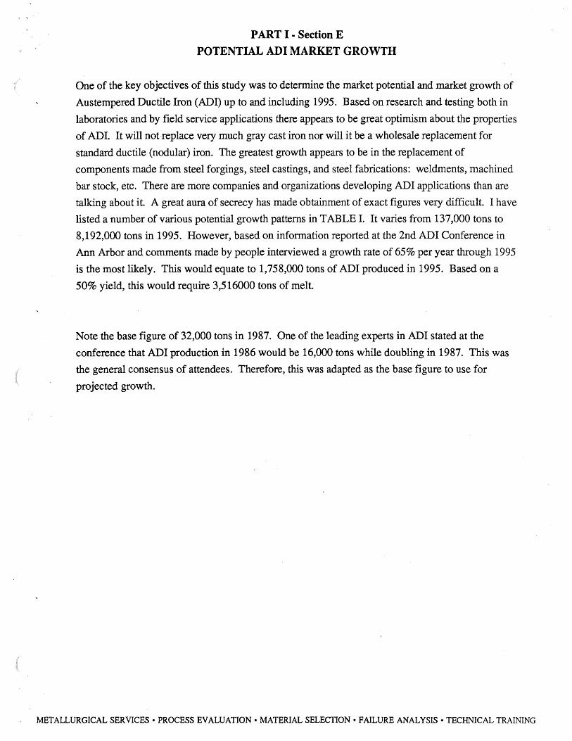
One of the key objectives of this study was to determine the market potential and market growth of
Austempered Ductile Iron (ADI) up to and including 1995. Based on research and testing both in
laboratories and by field service applications there appears to be great optimism about the properties
of ADI. It will not·replace very much gray cast iron nor will it be a wholesale replacement for
standard ductile (nodular) iron. The greatest growth appears to be in the replacement of
components made from steel forgings, steel castings, and steel fabrications: weldments, machined
bar stock, etc. There are more companies and organizations developing ADI applications than are
talking about it. A great aura of secrecy has made obtainment of exact figures very difficult. I have
listed a number of various potential growth patterns in TABLE I. It varies from 13 7 ,000 tons to
8,192,000 tons in 1995. However, based on information reported at the 2nd ADI Conference in
Ann Arbor and comments made by people interviewed a growth rate of 65% per year through 1995
is the most likely. This would equate to 1,758,000 tons of ADI produced in 1995. Based on a
50% yield, this would require 3,516000 tons of melt.
Note the base figure of 32,000 tons in 1987. One of the leading experts in ADI stated at the
conference that ADI production in 1986 would be 16,000 tons while doubling in 1987. This was
the general consensus of attendees. Therefore, this was adapted as the base figure to use for
projected growth.
METALLURGICAL SERVICES• PROCESS EVALUATION• MATERIAL SELECTION• FAILURE ANALYSIS• TECHNICAL TRAINING

1987 1988 1989 1990 1991 1992 1993 1994 1995
1987 1988 1989 1990 1991 1992 1993 1994 1995
TABLE I
POSSIBLE ADI GROWTH RATES
20% 30% 40% 50%
32000 32000 32000 32000 38400 41600 44800 48000 46080 54080 62720 72000 55296 70304 87808 108000 66355 91395 122931 162000 79626 118813 172103 243000 95551 154458 240945 364500
114661 200795 337323 546750 137594 261033 472252 820125
65% 70% 80% 90%
32000 32000 32000 32000 52800 54400 57600 60800 87120 92480 103680 115520
143748 157216 186624 219488 237184 267267 335923 417027 391355 454354 604661 792351 645733 722402 1088391 1505468
1065461 1313083 1959104 2860389 1758010 2232242 3526387 .5434740
"Stratecasts as of April 1986" Forecasts 100000 Tons 1990
200000 Tons 1992
*All figures are net tons.
60%
32000 51200 81920
131072 209715 335544 536870 858993
1374389
100%
32000 64000
128000 256000 512000
1024000 2048000 4096000 8192000
METALLURGICAL SERVICES• PROCESS EVALUATION• MATERIAL SELECTION• FAILURE ANALYSIS• TECHNICAL TRAINING

-< CD c '""
-o <.O ()) Ch
-<.O cg <.O
-CD CD ~
-U) U) (JI
Prof ected Demand U1 0 0 0 ..... 0 CD 0 O>
(annual tons)
..... (J1 N CD CD O> m
CD > Q ~ C/J ........ (b a.. t; 0 ~ :J
O') ~ (Jl > ~ z G1 ~ -, 0 :E n ('"+-
:::,-~
;o ~ Q ,...+ < (1)
~
METALLURGICAL SERVICES• PROCESS EVALUATION• MATERIAL SELECTION• FAILURE ANALYSIS• TECHNICAL TRAINING

1 .,
PART I- Section F
THE SUITABILITY OF KR IRON FOR PRODUCING ADI
Charge materials used for producing ADI have the same requirement as those used to produce other
cast irons. They must have a composition of such a nature that they can be melted economically
while maintaining proper iron chemistry.
In most, if not all, ductile iron foundries the most predominant charge material is the returns from
the casting process: downsprue, gates, runner bars, risers, and any scrap casting which may
occur. The amount of returns available for remelt depends on the casting yield. The casting yield
is calculated by dividing the weight of castings produced by the total weight of iron poured into the
mold. A figure used quite commonly throughout industry, and verified in the survey, is 50%
yield. This obviously means 50-55% of the charge could consist of returns. This leaves 45-50%
to be made up of other materials. For gray iron and some ductile, this can consist entirely of steel
scrap. Steel scrap is low in carbon and silicon but unless it is a premium grade of deep drawing
steel (.25 - .30%) the manganese level is about .60 - .90%. For gray iron and pearlite ductile, this
is no problem, but a ferrite grade of ductile cannot tolerate it. As ADI has been found even more
sensitive to manganese over .30%, the high steel charge would not do. The bath would need to be
diluted with a low manganese source of iron units. Some possible sources of these iron units are
low manganese steel, sorelmental, direct reduced iron pellets or briquettes, and KR iron.
Low manganese steel is an item which is not readily available to all producers. Certain captive
automotive foundries utilize it as it is internal scrap. However, it usually requires more energy to
melt plus a need for carbon and silicon additions must be made. Direct reduced iron (DRI) is low
in residuals but usually creates an unmanageable slag condition during the melt. Sorelmetal works
extremely well as it low in manganese and silicon but it is on expensive charge material. KR iron is
almost as attractive as Sorelmetal in regards to chemistry. The silicon is higher and the manganese
is somewhat higher than soremetal. The silicon in Sorelmetal is .07%. While KR iron has a .80%.
The manganese in soremetal is .01 % while KR iron has a .15%. If Sorelmetal was used to dilute
the manganese level in the bath a maximum amount of 25 % of the charge weight would need to be
Sorelmetal. If KR iron was used there would be a need for 35 % of the charge weight to be KR
iron. See calculations on the next page:
METALLURGICAL SERVICES• PROCESS EVALUATION• MATERIAL SELECTION• FAILURE ANALYSIS• TECHNICAL TRAINING

PART I- Section F, continued
THE SUITABILITY OF KR IRON FOR PRODUCING ADI
Sorelmetal Mn
RETURNS 500 lbs. X .30% = 1.5 lbs.
STEEL SCRAP 250 lbs. X .60% = 1.5 lbs.
Sorelmetal 250 lbs. X .01 % = IQ2~ lbs1
1000 3.025 lbs. .302%Mn
KR IRON RETURNS 500 lbs. X .30% = 1.50
STEEL SCRAP 150 lbs. X .60% = .90
KR IRON 350 lbs. X .15% = .ui25. .1000 2.925 lbs . .2925%Mn
One can see that KR iron will not be as an effective diluent as Sorelmetal but it is still very suitable
as a charge material for ADI. There also needs to be some research done as to the physical shape
the KR iron pig would take. This would affect charging and melting operations. A 30 to 40 pound
pig seems to be the optimum size. That will ease handling plus it is easier to trim the charge while
weighing it up.
Overall KR iron seems to be a very attractive charge material for ADI and other ductile iron.
METALLURGICAL SERVICES• PROCESS EVALUATION• MATERIAL SELECTION• FAILURE ANALYSIS• TECHNICAL TRAINING

PART II
The potential demand for KR iron appears to be quite favorable.
Twenty-three persons from foundries, heat treating companies, and related technology suppliers
were interviewed. All the foundries interviewed produced ductile iron and a few of them also
produced gray iron. Everyone producing ductile iron had experimented with ADI and plan on
producing it as user demand in~reases.
The foundry people interviewed were either present plant metallurgists or foundry managers who
had been chief metallurgists. They were all very knowledgeable about the actual charge mixes
being used in their melt departments.
Invariably the charge material common to all the foundries was foundry returns (- 50% of the
charge.) Only two used pig iron in their gray iron whole at least half used pig iron in their ductile.
The material used in almost all cases was Sorelmetal. The balance of the charge material ranged
from steel busheling and burnings to specially prepared shredded deep drawing grade steel which is
low in manganese. The primary reason more pig iron wasn't used in ductile iron was the cost
factor. The steel scrap being purchased ranges from $70 - $105 per ton. The average price for
Sorelmetal FOB Q.I.T.'s plant in Canada is approximately $185. After transportation costs are
added, a price of $210 - $220 per ton is likely.
The chemistry of the KR iron was described to the interviewees and most found it attractive as a
source of low manganese. Three people expressed concern about the silicon (Si) level being over
.50%. Their particular method of making ductile iron n~essitates a low silicon content in the base
iron. They felt they could work around it however. KR iron is not a trade-off with Sorelmetal
when looking at just manganese but some concerns were expressed about trace elements of
chromium, vanadium, and titanium in Sorelrnetal which might adversely affect ADI properties.
This remains to be proven as a valid fear but it is definitely a possibility.
(The material seems to be attractive at a price between $125 and $150 per ton. Even at $150, it
appears as if a market exists for all the annual output of a facility on the Iron Range by 1995.)
METALLURGICAL SERVICES• PROCESS EVALUATION• MATERIAL SELECTION• FAILURE ANALYSIS• TECHNICAL TRAINING

Part II Page2
Developing demand curves for gray iron and ductile iron was relatively straight forward. The
demand curves for the ADI market was projected based on comments of the interviewees about
how strongly they endorsed the low manganese prerequisite for production of ADI. As Sorelmetal
is one of the only _low manganese charge materials available, the pricing was based against thpse
figures.
Some of the present foundries using "home" shredded automotive scrap may be in the market in the
mid-90's as a movement is underway to convert more auto body sheet metal to high impact
thermoplastics. This could cut the shredded auto scrap supply considerably. This will have to be
followed closely.
METALLURGICAL SERVICES• PROCESS EVALUATION• MATERIAL SELECTION• FAILURE ANALYSIS• TECHNICAL TRAINING

PERSONS INTERVIEWED FOR ADI AND KR SURVEY
Alan Holtz - Metallurgist Am cast Meadville, PA (814) 724-2600
Brent McComb - Manager of Metallurgy Archer Creek Plant · Lynchburg Foundry Lynchburg, VA (804) 528-8711
Robert Bigge - Foundry Metallurgist Briggs & Stratton Milwaukee, WI (414) 771-4210
Dale Kretschmer - Technical Director Brillion Iron Works Brillion, WI (414) 756-2121
Jay J anowak - Mgr. Foundry Mktg Dvlpmnt Climax Molybdenum Division Amax Arlington Heights, IL (312) 392-71 ()()
CJ. "Jim" Peterson - Technical Director Columbus Foundry Columbus, GA (404) 323-5221 Ext. 225
Robert Mathews - Metallurgist Dana Corporation New Castle, IN (317) 529-1560
Richard Kryzanek - Manager Metallurgy John Deere Foundry Deere & Company East Moline, IL (309) 752-6858
Bernardo Morgensteren - Casting Manager Ford Castings Division Ford Motor Company Detroit, MI (313) 594-1473
Bela Kovacs - Materials Engineer Ford Motor Company Detroit, MI (313) 592-2535
Lee Edwards - Chief Metallurgist Central Foundry Division General Motors Company Saginaw, MI (517) 776-4865
Al Alagarsamy - Corporate Technical Director Grecie Foundry Reedsburg, WI (608) 524-6424
James Paternoster - Technical Director Hayes Albion Albion, MI (517) 629-2141
William Minor - Marketing Manager J & A Steel Treating Elk Grove Village, IL (312) 437-1980
Forest Barnhart - Chief Metallurgist Kingsbury Castings Inc. LaPorte, IN (219) 393-3122
Roland Reutz - Metallurgist Kohler Company Kohler, WI (414) 457-4441 Ext. 7566
Joseph Lincoln - Consultant Lincoln Associates Milford, MI (313) 685-7 464
Fred Preston - Plant Metallurgist Lufkin Industries Lufkin, TX (713) 634-2211
Al Bielke - Foundry Manager Murray Foundry Wausau, WI (715) 845-3155
P. Halasya "Paul'' Mani - Technical Director Wagner Castings Co. Decatur, IL (217) 428-7791
Peter Haakanson - Metallurgist Wells Manufacturing Skokie, IL (312) 966-5050 Ext. 255
William Powell - Manager of Melt & Metallurgy Waupaca Foundry Waupaca, WI (715) 258-8511
Dr. Carl Loper, Jr. - Prof. of Metallurgy Eng'g. Metallurgical Engineering Department College of Engineering · University of Wisconsin - Madison (608) 262-2562
METALLURGICAL SERVICES• PROCESS EVALUATION• MATERIAL SELECTION• FAILURE ANALYSIS• TECHNICAL TRAINING

KR IRON MARKET SURVEY INTERVIEW FORM
1. What is your annual tonnage of production?
Ductile Gray ________ _
2. What is your annual capacity? Ductile ________ _
3. What is your average casting yield?
Ductile % Gray %
4. What are you main sources of iron units in 'your melt charge?
Returns % Pig Iron %
Steel Scrap %
5. If you do use pig iron, what type(s) do you use?
7. Do you now produce ADI? D Yes If yes, how much? ____________ _
8. If not now, do you plan to produce it in the future? 0Yes
Prospective tonnage? ___________ _
9. If you now produce it or intend to, would you purposely keep manganese level low?
0Yes 0No What level? ______________ _
10. Would you use any special charge material to maintain low manganese?
0Yes 0No What material? _____________ _
11. Would a low manganese pig iron similar to soremetal be an option if price was right?
0Yes 0No '
METALLURGICAL SERVICES• PROCESS EVALUATION• MATERIAL SELECTION• FAILURE ANALYSIS• TECHNICAL TRAINING

12. (KR) Do you know about KR iron?
0Yes D No
, 13. KR chemistry 4.22% C .80-1.00% Si .017% s
.019% p
.145%Mn
14. Would this be an attractive charge material at:
$200/ton $175/ton _____ _
$150/ton _____ _ $125/ton
15. How much would you buy at:
D $200/ton D $175/ton
D $150/ton D $125/ton
16. Would you use KR in conjunction with other charge material?
0Yes D No
METALLURGICAL SERVICES• PROCESS EVALUATION• MATERIAL SELECTION• FAILURE ANALYSIS• TECHNICAL TRAINING
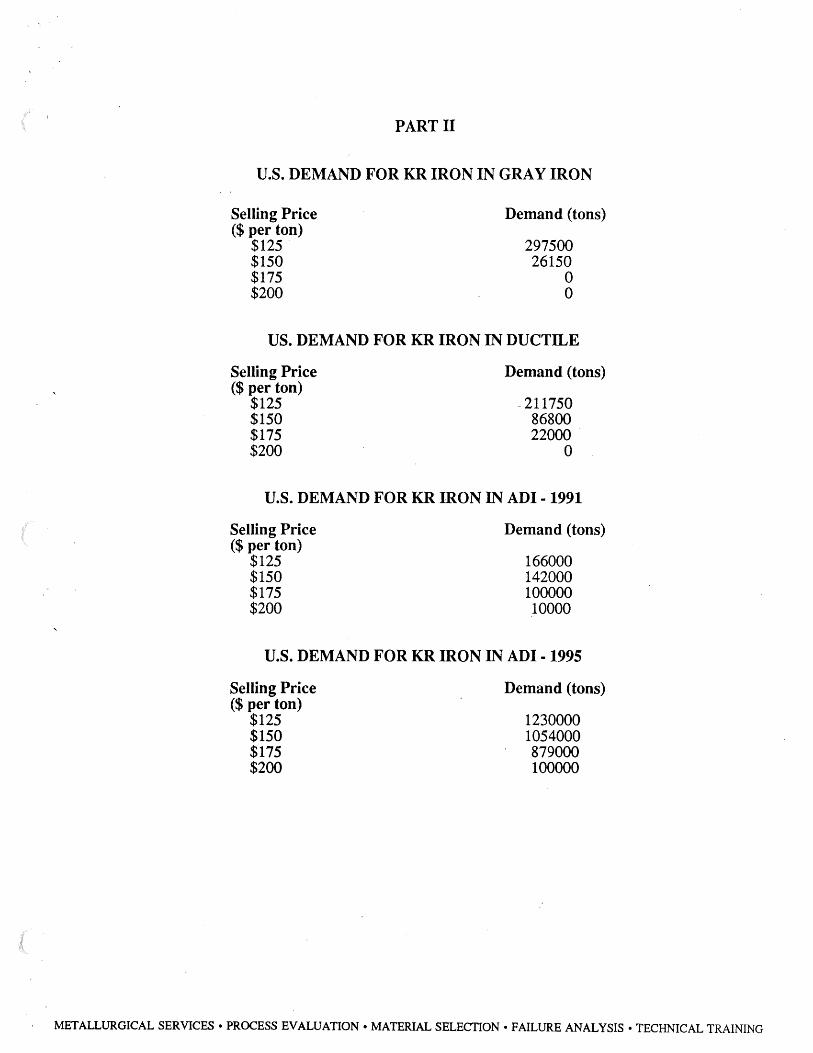
PARTII
U.S. DEMAND FOR KR IRON IN GRAY IRON
Selling Price ($per ton)
$125 $150 $175 $200
Demand (tons)
297500 26150
0 0
US. DEMAND FOR KR IRON IN DUCTILE
Selling Price ($per ton)
$125 $150 $175 $200
Demand (tons)
~ 211750 86800 22000 .
0
U.S. DEMAND FOR KR IRON IN ADI - 1991
Selling Price ($per ton)
$125 $150 $175 $200
Demand (tons)
166000 142000 100000 10000
U.S. DEMAND FOR KR IRON IN ADI - 1995
Selling Price ($per ton)
$125 $150 $175 $200
Demand (tons)
1230000 1054000 879000 100000
METALLURGICAL SERVICES• PROCESS EVALUATION• MATERIAL SELECTION• FAILURE ANALYSIS• TECHNICAL TRAINING

PART II
POTENTIAL KR IRON USAGE IN ADI AT VARIOUS PERCENTAGES
KR IRON AS PERCENT OF CHARGE Tons Castings Tons Melt 35% 30% 25%
1986 16000 32000 11200 9600 8000 1987 32000 64000 22400 19200 16000 1988 52800 105600 36960 31680 26400 1989 87120 174240 60984 52272 43560 1990 143748 287496 100623 86248 71875 1991 237184 474368 166028 142310 118590 1992 391353 782706 273947 234810 195675 1993 645733 1291466 452013 387440 322865 1994 1065461 2130922 745822 639275 532730 1995 1758010 3516020 1230607 1054800 879000
METALLURGICAL SERVICES• PROCESS EVALUATION• MATERIAL SELECTION• FAILURE ANALYSIS• TECHNICAL TRAINING

U> CD
-· ::s co .,, :!. 0 a>
,..-.. ~
"O CD , .. 0 ::s ..........
.-. N 0
.-. ~ 0
(7)
0
-00 0
t--J 0 0
0
Protected Demand (annual tons) -(JI 0 0 0 0 0 0 0 0 0
-CJ'1 0 0 0 0
t\.) 0 0 0 0 0
~ (JI 0 0 0 0
METALLURGICAL SERVICES• PROCESS EVALUATION• MATERIAL SELECTION• FAILURE ANALYSIS• TECHNICAL TRAINING

Proiected Demand (annual ions) "-> ~ ~ ~ "->
(J'I a (J'I 0 gm 0 a 0 0 0 0 0 0 0 0 0 0 0 0
0 0 a 0 0 o~ -I\) tcj 0
~ > z t::'
- ~ ~ 0
U) ~ CD
:J ~ co ~ ,., I ,
~ -· ~ () (]) en 0 ,.-..,. 0 ~ z '"O
CD ,...... , z ..... 0
~ :::J ..__,, c::: CX>
0 n ~ ~
t'-4 tzj
~
~ tr-J 0 0 0 z
METALLURGICAL SERVICES• PROCESS EVALUATION• MATERIAL SELECTION• FAILURE ANALYSIS• TECHNICAL TRAINING

Proiected Demand (annual tons)
-. ~
(/) (I)
-· ::s <O
-0 :::!. (') (]) 0)
,-..... 0
~
"'t:J m , .... 0 ::J ......... -00
0
METALLURGICAL SERVICES• PROCESS EVALUATION• MATERIAL SELECTION• FAILURE ANALYSIS• TECHNICAL TRAINING

CJ) CD
-· :J . co -0 .., -· 0 a> ~
~
-0 t'D ..., ..... 0 :J ._,
Profected Demand (annual tons) U1 0
8 -: ~c _o o ~ m~ N-+-~~~~~~--1...~~~~~~~~~~~~~----
0
-..... 0
_.. 0) 0
-00 0
to-.> 0 0
METALLURGICAL SERVICES• PROCESS EVALUATION• MATERIAL SELECTION• FAILURE ANALYSIS• TECHNICAL TRAINING

PART III
The 2nd INTERNATIONAL CONFERENCE on
AUSTEMPERED DUCTILE moN
The conference was held on March 17-19, 1986 at the University of Michigan in Ann Arbor,
Michigan. The primary sponsors were: ASME - Gear Research Institute ASME - Design Division Amax, Inc.
The Co-Sponsors were: American Foundrymen's Society American Gear Manufacturers Association American Society for Metals British Cast Iron Research Association Ductile Iron Society (USA) German Foundrymen's Association Iron Castings Society (USA) Japan Ductile Cast Iron Association Society of Automotive Engineers University of Michigan
This 2-1/2 day conference was attended by 285-300 persons from worldwide, all with keen interest
in ADI. The speakers at the conference were from the United States, West Germany, France,
England, Finland, Sweden, Switzerland, and Japan. The general consensus seemed that the
United States ADI technology was the furthest along the path of anyone. Good work has been
done in England, West Germany, and Japan but overall progress has been the greatest in the U.S.
There were a few key points of criteria established at this conference which will affect successful
production of ADI. First, the maximum austenitizing temperature which had been specified as high
as 1700°F was recommended to be no higher than l 600°F. Th.ere could be a few exceptions to this
but the range of 1550-1600°F appears to be the norm to use. Higher temperatures caused too much
carbon to go into solution in the austenite which resulted in retained austenite in the matrix along
with acicular ferrite and carbon rich stable austenite. This retained as untransformed austenite could
transform to martensite and cause embrittlement of the ADI.
The second key point which seemed to have consensus was the maintenance of a maximum
manganese level of .30%. Higher levels of Mn appear to cause uneven solubility of carbon leading
to erratic fatigue and fracture toughness properties of the ADI. This lower manganese requirement
is no doubt going to require a greater source of low manganese iron units as the production of ADI
increases.
The third point was the expression of desirability of a high nodule count. A nodule count of
150/mm2 or higher was endorsed. This helps ensure better fatigue and wear properties as well as
fracture toughness.
METALLURGICAL SERVICES• PROCESS EVALUATION• MATERIAL SELECTION• FAILURE ANALYSIS• TECHNICAL TRAINING

2nd International Conference Page2
There were many examples of applications already converted to ADI from steel forgings, steel
fabrications, steel castings, ductile iron castings, and even some gray iron castings. The main
material being replaced will probably be steel forgings which are either Quench and tempered or
carburize case hardened. No one fully addressed the question of machining before or after
austempering which needs of further dialogue. This is an area of great concern due to potential
uneven dimensional changes after the austempering.
Overall the outlook for the future of ADI was declared extremely healthy and there is a definite
growing market.
METALLURGICAL SERVICES• PROCESS EVALUATION• MATERIAL SELECTION• FAILURE ANALYSIS• TECHNICAL TRAINING
APPENDIX A
(These guidelines ~ere presented at the 2nd International Conference on Austempered Ductile Iron.
specific chemistries and heat treating temperatures have already been changed by consensus although
the enclosed could still be adopted by ASI'M and other standards societies.)
GUIDELINES FOR AUSTEMPERED DUCTILE IRON
PREFACE
These guidelines are intended to serve as an aid to producers and heat treaters which will enable them
to confidently make products that consistently meet the standards of reliability demanded by casting
users. It is expected that these guidelines will be used by the various national and international
organizations, responsible for standardization, to prepare realistic standard specifications for
austempered ductile iron.
METALLURGICAL SERVICES• PROCESS EVALUATION• MATERIAL SELECTION• FAILURE ANALYSIS• TECHNICAL TRAINING
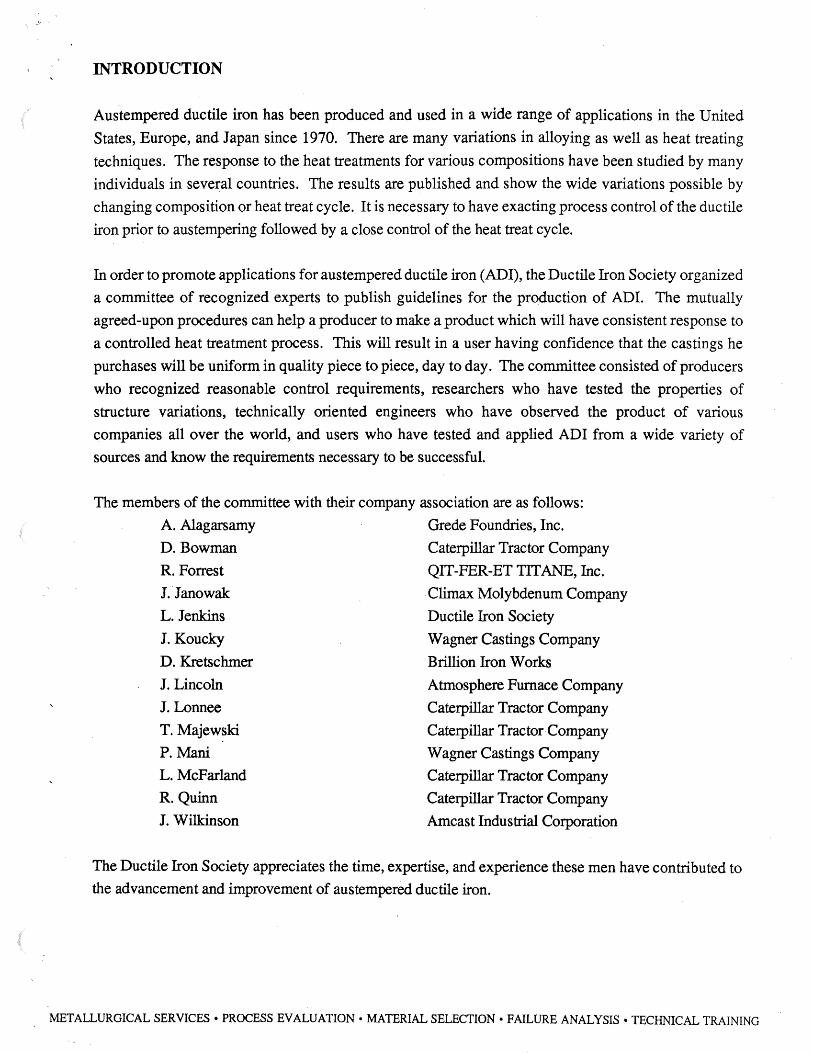
INTRODUCTION
Aus.tempered ductile iron has been produced and used in a wide range of applications in the United
States, Europe, and Japan since 1970. There are many variations in alloying as well as heat treating
techniques. The response to the heat treatments for various compositions have been studied by many
individuals in seve~al countries. The results are published and show the wide variations possible by
changing composition or heat treat cycle. It is necessary to have exacting process control of the ductile
iron prior to austempering followed by a close control of the heat treat cycle.
In order to promote applications for austempered ductile iron (ADI), the Ductile Iron Society organized
a committee of recognized experts to publish guidelines for the production of ADI. The mutually
agreed-upon procedures can help a producer to make a product which will have consistent response to
a controlled heat treatment process. This will result in a user having confidence that the castings he
purchases will be uniform in quality piece to piece, day to day. The committee consisted of producers
who recognized reasonable control requirements, researchers who have tested the properties of
structure variations, technically oriented engineers who have observed the product of various
companies all over the world, and users who have tested and applied ADI from a wide variety of
sources and know the requirements necessary to be successful.
The members of the committee with their company association are as follows:
A. Alagarsamy Grede Foundries, Inc.
D. Bowman Caterpillar Tractor Company
R. Forrest QIT-FER-ET TITANE, Inc.
J. Janowak Climax Molybdenum Company
L. Jenkins Ductile Iron Society
J. Koucky Wagner Castings Company
D. Kretschmer
J. Lincoln
J. Lonnee
T. Majewski
P. Mani
L. McFarland
R. Quinn
J. Wilkinson
Brillion Iron Works
Atmosphere Furnace Company
Caterpillar Tractor Company
Caterpillar Tractor·Company
Wagner Castings Company
Caterpillar Tractor Company
Caterpillar Tractor Company
Amcast Industrial Corporation
The Ductile Iron Society appreciates the time, expertise, and experience these men have contributed to
the advancement and improvement of austempered ductile iron.
METALLURGICAL SERVICES• PROCESS EVALUATION• MATERIAL SELECTION• FAILURE ANALYSIS• TECHNICAL TRAINING

SECTION I
PRODUCTION CONTROL OF IRON FOR AUSTEMPERING
Segregation Statement: Segregation is a major concern in the achievement of consistent mechanical properties.
Composition, nodule count, and section size, influence the level of segregation. Segregation
particularly interferes in obtaining toughness and short austempering time. In general, high
nodule count and controlled alloy levels; (Mn, Mo, Ni, Cu, P, Cr, Si) are preferred. As
section size increases, molybdenum is increased and manganese, chromium, and phosphorus
are generally reduced.
The key requirement is to have a narrow composition range to ensure consistent heat treat response.
The target composition range shall be agreed upon between the user and producer and shall be held
within the operating range.
Chemical Analysis:
NOTES:
Element Carbon 1
Silicon 1
Manganese 2 Phosphorus 3
Copper
Nickel
Molybdenum
Chromium
Titanium
Magnesium 4 Others 5
Element Range 3.2 - 3.8
2.5 - 3.0
.35Max.
.03Max.
LOO Max.
3.00Max.
.50Max.
.07Max.
.04Max.
.06Max.
1. Carbon and Silicon should be controlled to minimize porosity.
Operating Range ±.20
± .15
±.05
±.10 ±.10 ±.05
2. For a higher manganese content, a minimum nodule count must be agreed upon between
producer and user.
3. For any phosphorus in excess of .03 maximum, agreement should be reached between casting
user and the producer because of toughness consideration.
4. Maintain lower magnesium level which will produce satisfactory nodularity.
5. Tin, antimony and arsenic - the amount allowable will be agreed upon between casting
producer and user.
METALLURGICAL SERVICES• PROCESS EVALUATION• MATERIAL SELECTION• FAILURE ANALYSIS• TECHNICAL TRAINING

SECTION II
MICROSTRUCTURE OF IRON PRIOR TO AUSTEMPERING AS1M A 536 and AFS "Foundrymen's Guide to Ductile Iron Microstructures" are two recommended
references for base ductile iron.
A. Nodularity Graphite configuration shall be 80% minimum spheroidal conforming to ASTM A24 7, Type I
and Type II at 100 X magnification.
B. Nodule Distribution: Uniform nodule distribution preferred. Method of illustration to be developed.
C. Nodule Count: Sufficient to minimize segregation. Specific numbers may be agreed upon by casting producer
and user.
D. Carbides: Goal is to have no carbides. Specific amount to be decided by agreement between casting
producer and user.
E. Porosity: Goal is to have no porosity. Specific amount to be decided by agreement between casting
producer or heat treater and user.
F. Percent Pearlite: Pearlite-ferrite as-cast ratio to be established by agreement between casting producer or heat
treater and user.
G. Inclusions and Matrix Cleanliness: Goal is to have minimum inclusions in the matrix.
H. Segregation: Goal is to have no segregation which contributes to "white etching structure" distribution after
austempering.
METALLURGICAL SERVICES• PROCESS EVALUATION• MATERIAL SELECTION• FAILURE ANALYSIS• TECHNICAL TRAINING

SECTION Ill
AUSTEMPERING HEAT TREATMENT
A. Pre-Austempering Heat Treatment: 1. Ferritizing heat treatment may be done on castings provided the maximum temperature
used for ferritizing does not exceed the austenitizing temperature for subsequent
austempering.
2. Castings shall not be quenched_ and tempered prior to austempering.
B. Austenitizing Temperature: Austenitizing temperature to be maintained within± 10°F. The specific austenitizing
temperature is a function of:
1. Composition.
2. Starting microstructure.
3. Final mechanical properties desired.
Range for austenitizing temperature is 1500°F - 1700°F. Actual austenitizing temperature to be
agreed between casting producer or heat treater and user.
C. Austenitizing Time: Range 30 minutes - 2 hours at temperature.
Austenitizing time to be maintained within ± 5 minutes.
D. Furnace Atmosphere: Controlled atmosphere desired to prevent scale, decarburization, and surface carburuzation.
E. Time to Transfer the Castings to Quench: Depends on composition and section size and must be determined for each use and closely
controlled to insure unif onnity lot to lot
F. Austempering Temperature: Range 450°F. - 750°F. This temperature to be controlled within the range of ±10°F.
G. Time at Austempering: 30 minutes - 2-1/2 hours at temperature.
No more than ±10% variation in austempering time permitted once the desired time is
established.
Specific austempering time to be established for each composition and to be agreed upon
between casting producer and user.
METALLURGICAL SERVICES• PROCESS EVALUATION• MATERIAL SELECTION• FAILURE ANALYSIS• TECHNICAL TRAINING

SECTION Ill, continued
NOTE: Excessive austempering time will reduce mechanical properties.
H. Post Cooling: Castings, other.than gears, shall be cooled so as to avoid martensite formation.
I. Post Austempering Heat Treatment: Once the castings have been austempered, no tempering will be permitted.
J. Re-Austenitizing: Reheat treatment of austempered ductile iron castings may reduce properties, therefore, it may
only be done as agreed upon between casting producer or heat treater and user.
SECTION IV
MICROSTRUCTURE AFfER HEAT TREATMENT
A. The final microstructure of austempered ductile iron must be agreed upon between casting
producer or heat treater and user.
B. The microstructure shall be free of "white etching structure" when etched with 2% Nital and
viewed at 50 X magnification. illustrations to be developed.
C. Photomicrographs of acceptable and non-acceptable structures must be generated between
casting producer or heat treater and user.
D. Since metallographic techniques for austempered ductile iron are more critical than normal
ductile iron, caution should be taken m interpreting structures.
E. The preferred microstructure of austempered ductile iron is a matrix containing bainitic ferrite
and carbon enriched austenite.
F. Decarburization Restricted as follows on the surface:
1. No decarburization allowed on machine surfaces.
2. M.A.D. (Maximum Affected Depth in mm on unmachined surfaces equals 0.5 + (.02 times
the maximum section thickness in mm.)
3. No surface carburization permitted.
METALLURGICAL SERVICES• PROCESS EVALUATION• MATERIAL SELECTION• FAILURE ANALYSIS• TECHNICAL TRAINING

SECTION V
MECHANICAL PROPERTIES (MINIMUM)l
Yield Strength Brinell Hardness 3 Impact Energy2 Grade Tensile Strength (.2% Offset) Elongation
N/MM2 Nn..1M2 Ft.
Ksi Ksi B.I.D. B.H.D. lbs. Joules 1 125 860 80 550 10 3.40-3.70 269-321 75 105
2 150 1035 100 690 7 3.20-3.50 302-363 65 90
3 175 1205 120 830 4 2.90-3.20 363-444 45 65
4 200 1380 140 965 2 2.80-3.10 388-477 30 40
The mechanical properties are for test bars machined from 1 inch Y-blocks in accordance with ASTM
A-536.
1. In accordance with A.S.T.M. E-8.·
2. Unnotched Charpy (A.S.T.M. E-23) at 22C± 7C.
Four specimens tested, lowest value discarded, then average the remaining three. The average
must meet the minimum requirement
Frequency of the impact test to be by agreement between casting producer or heat treater and
user.
3. Hardness does not assure indicated properties.
REFERENCES:
A.F.S. Foundrymen's Guide to Ductile Iron Microstructures.
A.S.T.M. A247
A.S.T.M. A536-84
A.S.T.M. E-8
A.S.T.M. E-23
METALLURGICAL SERVICES• PROCESS EVALUATION• MATERIAL SELECTION• FAILURE ANALYSIS• TECHNICAL TRAINING
