march 2013 1 / 19 - rbtec lpu 304... · ip-ironclad-march 2013 2 / 19 ... connect the contact...
TRANSCRIPT

March 2013 1 / 19

RBtec IRONCLAD Product Information
IP-IRONCLAD-March 2013 2 / 19
GENERAL The Ironclad line sensor cable is a passive electronic intrusion detector system. The system is ideal for outdoor protection and can be easily installed on fences, on a concertina razor coil on a roofs and solid walls or for indoor use to protect vaults, strong rooms etc. The Ironclad sesore is an armour cable based on vibration sensor cable based on audio frequency (AF) miniature sensor cable, known as microphonic technology, featuring digital signal processing (DSP) and dual zone signal processing unit. The Ironclad offers a solution for intrusion detection by the analysis of typical vibration patterns made by a forced entry attempt. The system can recognize motion caused by an attempt to pass through the fence and disregard signals caused by weather conditions, preventing nuisance alarms. This is an easy-to-install and easy to adjust system, it will provide the end user an economic and highly secure perimeter protection system, with a very high probability of intruder detection and relatively low rate of false alarms. The Ironclad can be permanently or temporarily installed. It is designed to interface with a conventional intruder alarm system or to be integrated with RBtec’s When the RBtec INTRUDALERT Control Interface Unit (IA-6500) and software is used as the primary operator interface, it gives the system the ability to monitor and control the performance of the entire system. Standard accessories that can be added are a PC computer and a monitor to display a customized site map. With this configuration the system is compatible with all types of security sensors for outdoor or indoor use and can be easily interfaced for integration and control of complementary systems, such as Access Control systems and CCTV systems, installed at key points to provide real time assessment capability.

RBtec IRONCLAD Product Information
IP-IRONCLAD-March 2013 3 / 19
Principle of Operation The signal processor receives and analyzes the signals generated by the Ironclad sensor cable and detects minute vibrations in the fence. The sensor has independent adjustments and thresholds for each type of intrusion and the processor identifies, by type whether a cut intrusion or climb intrusion has occurred.
System Advantage The Ironclad Sensor Line Cable has a life expectancy of 10 years, is easy to install and non obstructive to the eye. This cable is attached directly to the fence with cable ties. The sensor is totally passive and has different ranges of sensitivity that will allow adapting it to any specific application. The zone starts at the electronic processor (Analyzer) and ends at the MCT- End Line protection module.

RBtec IRONCLAD Product Information
IP-IRONCLAD-March 2013 4 / 19
The IRONCLAD system includes several main components: Ironclad Sensor Line Cable - The Ironclad Sensor cable is attached to the desired-to-protect structure (fence/wall), converting the whole structure into a gigantic vibration of high fidelity, which will detect any kind of intrusion. The electric output of this cable is a highly accurate reproduction of all sounds, generated by the fence/wall. LPU-304 An electronic processor that continuously monitors the cable signal output and detects any attempt to penetrate the perimeter. The analyzer is designed to ignore signals generated by rain, wind or birds. It utilizes highly advanced microprocessor technology in a microprocessor and is installed inside an IP65 rated weatherproof box. The analyzer scans the integrity of the sensor line, thus monitoring the terminal that has been integrated to the cable. If the cable is cut, damaged or interfered in any way, the analyzer will immediately detect it, and activate a warning signal. The LPU-304 is design to control up to two zones of 305m (1000Ft) with relay outputs. The analyzer is equipped with 4 inputs for external devices and 4 Solid States Relay. Meteorological unit can be connected for Weather Compensation Unit.
Electronic kit with LPU-304
Analyzer module

RBtec IRONCLAD Product Information
IP-IRONCLAD-March 2013 5 / 19
End Of Line Resistor module (MCT) The End of Line Resistor is connected at the end of the zone to complete the circuit. It can also be used as an extension unit when the zone extends more than 305m(1000Ft.). NOTE: For single and dual zone kits, MCT modules are built-in at the sensor cable ends.
METEOROLOGICAL UNIT (OPTIONAL)
In medium to large fenced perimeter protection systems, movement resulting from strong winds, rain and hail can cause a sensor to trigger a false or nuisance alarm.
The VX-25 weather compensating unit is specially built to automatically compensate system’s sensitivity for changing climatic conditions. Wind velocity measured by a 3–cup- anemometer is translated into analog DC voltage and rain/hail conditions are measured by 3 concave plates and are translated into digital pulses. These signals are converted into “pseudo alarm” and are fed into the transponder card, temporarily creating new threshold and adjusting system’s sensitivity to a new “zero” state. Only true alarms will now trigger the system and all other weather related alarms are eliminated.
Rain sensor: The rain sensor discs and shock sensors are vibration sensing units whose function is to detect the vibrations caused by rain or hail drops. These vibrations are translated into electronic signals and transmitted to the field Transponder card(SPU-2004). Wind sensor: A 3 cup manometer is mounted at the top of the center post holding the rain sensor discs. This wind vain manometer produces a voltage frequency, which change with the changes in wind speed. This frequency is converted to electronic signals and transmitted to the Control card. The weather Interface Unit is a conversion circuit, which transforms the AC frequency sent by the wind manometer on the Weather Compensation Unit to a DC analog voltage relative to the wind speed
MCT-X/MCT-R Extension Unit / End of Line Resistor

RBtec IRONCLAD Product Information
IP-IRONCLAD-March 2013 6 / 19
Specifications: Measures wind speed up to 100 mph.
Power consumption 12 VDC 5mA
Response time 0.5 seconds

RBtec IRONCLAD Product Information
IP-IRONCLAD-March 2013 7 / 19
Configuration Options The Ironclad is available in three configurations:
A complete installation kit for a single zone system.
A complete installation kit for a dual zone system.
Multi-zone system configuration by multiplying kits above.
All the above system configurations can be stand-alone or can be integrated with RBtec’s Command & Control system and software package. The standard length of each zone can be up to 1,000’ (305m) of sensor line cable.
The installation kits include all the materials necessary for installation. Individual zone length is determined by the physical borders of each zone. The sensor line cable will be supplied in carton roll dispensers of 1,000’ (305m) and will be cut to the correct length at the time of installation.
Single Zone Configuration
The basic Ironclad is a single zone system. The kit contains a single zone LPU-304 Analyzer unit with a single dry contact output, one carton roll of sensor cable 1,000’ (305m), one MCT End-of-Line Termination Module which is built-in the sensor cable and a package of 610 cable ties.
RBtec IRONCLAD Product Information
IP-IRONCLAD-March 2013 8 / 19
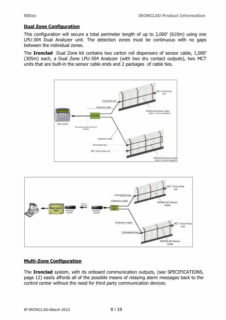
Dual Zone Configuration
This configuration will secure a total perimeter length of up to 2,000’ (610m) using one LPU-304 Dual Analyzer unit. The detection zones must be continuous with no gaps between the individual zones.
The Ironclad Dual Zone kit contains two carton roll dispensers of sensor cable, 1,000’ (305m) each, a Dual Zone LPU-304 Analyzer (with two dry contact outputs), two MCT units that are built-in the sensor cable ends and 2 packages of cable ties.
Multi-Zone Configuration The Ironclad system, with its onboard communication outputs, (see SPECIFICATIONS, page 12) easily affords all of the possible means of relaying alarm messages back to the control center without the need for third party communication devices.
RBtec IRONCLAD Product Information
IP-IRONCLAD-March 2013 9 / 19
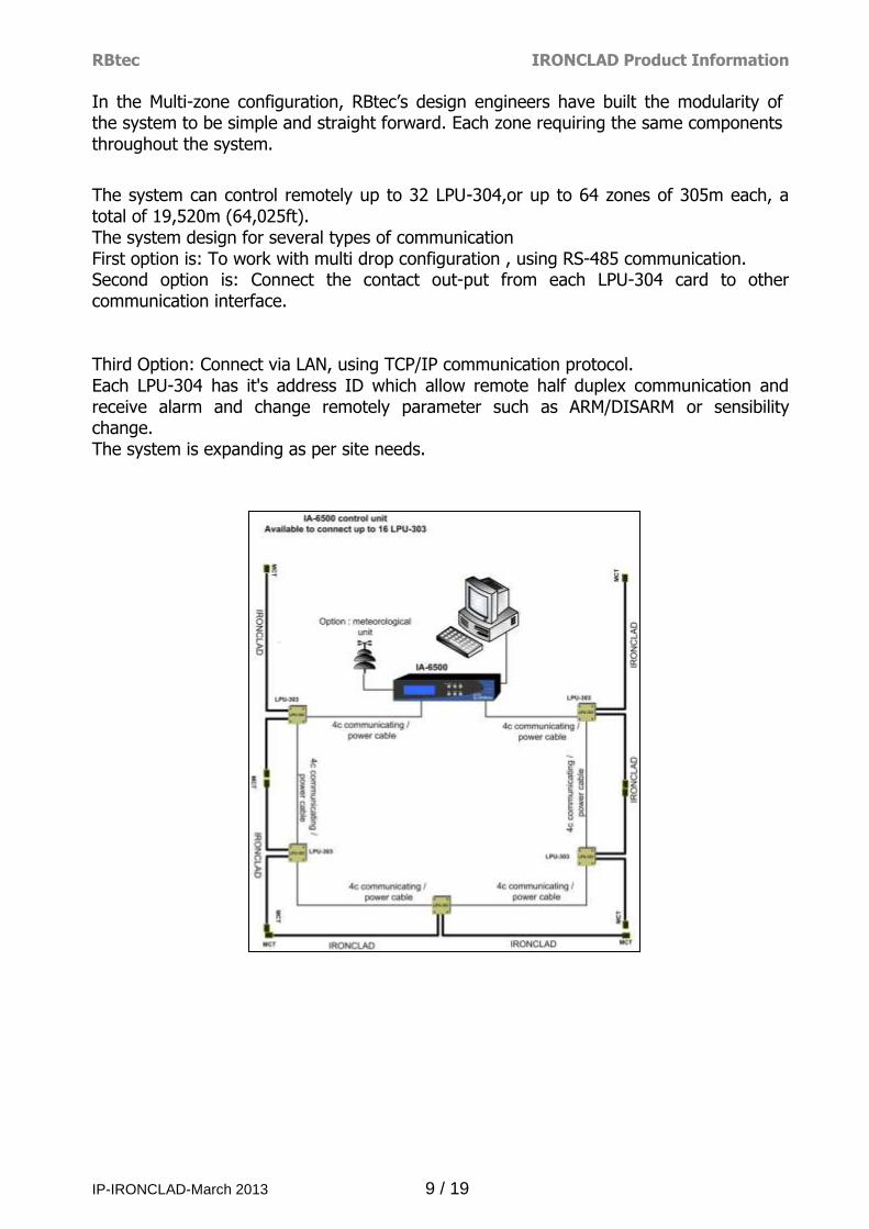
In the Multi-zone configuration, RBtec’s design engineers have built the modularity of the system to be simple and straight forward. Each zone requiring the same components throughout the system.
The system can control remotely up to 32 LPU-304,or up to 64 zones of 305m each, a total of 19,520m (64,025ft). The system design for several types of communication First option is: To work with multi drop configuration , using RS-485 communication. Second option is: Connect the contact out-put from each LPU-304 card to other communication interface. Third Option: Connect via LAN, using TCP/IP communication protocol. Each LPU-304 has it's address ID which allow remote half duplex communication and receive alarm and change remotely parameter such as ARM/DISARM or sensibility change. The system is expanding as per site needs.

RBtec IRONCLAD Product Information
IP-IRONCLAD-March 2013 10 / 19
Specifications:
LPU-304 Operating Power Requirements:
12 – 15VDC 40mA @ 12VDC
Lightening Protection: Gas Discharge Devices on all Inputs/Outputs & Communication line.
Alarm Outputs Intrusion and Line monitoring output for each zone. Dry contact relays with N.O. and N.C. contacts rated 1A @ 12VDC. Alarm output via Ethernet TCP/IP.
Alarm output via RS-485 Protocol. 4 alarm outputs SSR type corolating to aditional 4 inputs of sensors
Alarm Indicators Power Status LED.
Alarm Relay Status LED. Tamper Indication LED.
Connector: F type Coax connection Sensor Cable Inputs for each zone.
Enclosure: NEMA 4, IP-65 9.5 x 7.5 x 2.75” (24 x 19.5 x 7.0cm) Weight: 2.2 lbs (1Kg)
IRONCLAD Transducer Sensor Cable & Accessories: Maximum length/zone: 1000’ (305m). UV resistant 2 conductor coaxial cable. Diameter: 0.189” (4.8mm) Color: Silver
UV resistant cable ties (610 per Zone) Life expectancy 10 years field operation Weight 229.3 pound/mile (65 Kg/Km) Armored
MCT End Of Line Resistor card
Outdoor weatherproof Enclosure Box ultrasonic welded to the detection sensor line.
Life expectancy 10 years field operation
Environment: Operating Temperature: - 40° to 158°F (-40° to 70°C) Relative Humidity up to 98% non-condensing.
Options RS485: Intrudalert 5500 Protocol VX-25: Weather Compensation Unit

RBtec IRONCLAD Product Information
IP-IRONCLAD-March 2013 11 / 19
CONTROL ROOM COMPONENTS (OPTIONAL) Monitoring and control of the INTRUDALERT system is based on RBtec's VIDALERT control software or by the IA6500 Control Interface Unit. The control station located in the control room or a guard booth provides the operator the option to control, monitor, save and display all the security events within his area, manually or automatically.
IA -6500 Control Interface Unit The IA-6500 interface unit is designed to receive signals from the field transponder and the smart processing unit SPU-2004 and retransmit the processed data into the system’s central computer.
The IA-6500 contains the Central Control Card, a Back-Up Control Card, a Lightning Protection Card and a Power Supply.
Additional IA-6500 Control Interface Units may easily be added for larger perimeters using additional hardware to interface between several IA-6500 Control Interface Units and the Central Computer.
For larger perimeters, additional IA-6500 interface units can be added.
The IA-6500 interface unit has fully automatic backup capability in case of the PC or other hardware failure. In the event of PC hardware or software failure, the IA-6500 automatically takes command continuing the system’s operation without interruption.
Fully automated, the IA-6500 includes two internal control units, a full backup software program, an active LCD display panel and a rechargeable backup battery, all mounted on a standard 19” rack for easy access and installation.
A 15VDC power supply is installed in the unit serving both the IA-6500 and the smart processing unit SPU-2004 in the field.
Although inactive during normal system operation, the IA-6500 is always connected to the system in an ‘ON-GUARD’ mode. When PC failure occurs, the IA-6500 automatically takes control and continuous system operation is maintained through its on-board control panel.

RBtec IRONCLAD Product Information
IP-IRONCLAD-March 2013 12 / 19
Control Display Features
Key Function
Menu/Enter Move between menu options and confirm selections.
ESC Go to previous screen, cancel selections and move out of program to alarm screen.
UP Change values up
DOWN Change values down
ACK Acknowledge alarms and silent annunciator
DEL Delete alarm after acknowledge
VIDALERT software configuration
The VIDALERT system software is designed to operate under the Microsoft Windows operating system and uses the full power of Windows graphic capabilities.
The VIDALERT software program controls the complete VIDALERT system, enabling control and management via a single keyboard and monitor.
The PC monitor displays the present status of the entire perimeter in real time. The main screen displays a color graphic map of the secured site, clearly showing the perimeter zones in different colors. When an alarm is triggered the relevant zone will start blinking in red and an audible alarm will sound. From the main screen, the operator may use different keys to move through the system’s functions such as: Changing of zone sensitivities.

RBtec IRONCLAD Product Information
IP-IRONCLAD-March 2013 13 / 19
Changing of ‘Arm/Disarm’ status. Changing of the system ‘Time/Date’. Password enrollment for access authorization to system controls. Data bank access. Immediate help on current screen, quick help panel.
VIDALERT Software Program VIDALERT unique sensing and intrusion detection capabilities are enhanced by a PC based, active color graphic site map display, a series of screen display keyboard controlled function keys and a variety of communication and response capabilities to form a complete perimeter protection system.
Alarms are presented on the active color graphic site map as a flashing zone and announced by pre-recorded synthesized computer voice or a beeping sound. In addition, it can activate electronically integrated systems such as CCTV and auxiliary response equipment such as sirens, floodlights and automatic gates and barriers for the identification and capture of intruders.
From the perimeter map, the user has a complete overview of the entire protected site status including system ‘Arm/Disarm’ status.
A standard PC computer may be used with the system.
Data displayed on the screen (but not limited to):
Graphic site maps. Event screens. Status change screens. Sensitivity change screens. Historical data screens.
Hard copy and printout control. Built-in help screens. Voice announcement controls. Special customers’ tailored screens.
RBtec IRONCLAD Product Information
IP-IRONCLAD-March 2013 14 / 19
Alarms & Commands The Central Control is normally maintained in "monitoring" status. When an alarm is received, the system monitor indicates "alarm" status and the affected zones of the perimeter are immediately shown. Alarms are visually displayed and audibly announced by a ‘voice recording’ or beep, enhancing security personnel reaction. All alarm commands and events are recorded and stored for analysis and hard copy report printing.
The Control Interface Unit monitors and controls all alarm zones, as well as additional devices such as lighting, CCTV, horns, sirens and other physical response auxiliary devices. These devices are controlled and activated through the Smart Processor Units (SPU-2004).
Eight relay outputs per transponder are available for linking the Control Interface Unit with remote devices.
Alarm Communications, Analysis And Response VIDALERT’s unique sensing and intrusion detection capabilities are enhanced by a PC based, customizable ‘Active Color, Graphic Site Map Display’, a series of screens display keyboard controlled functions and a variety of communication and response capabilities, to structure an all inclusive perimeter defense system.
Alarms are presented on the Active Color Graphic Site Map, as a "flashing" zone and announced by pre-recorded, synthesized computer voice or a beeping sound.
Signals can then be transmitted to mobile units or to remote stations through RF radio, cable, or telephone /cellular communications.
In addition, activation of electronically integrated systems and response equipment such as; CCTV, sirens, floodlights, automatic gates and barriers can be initiated in order to locate, identify and capture would-be intruders.
Main Screen - Site Map From the perimeter map the user has a complete overview of the entire perimetric zone status, including the Alarm Status (whether there is an alarm or not) and Zone Arm Status.
Security Software VIDALERT’s Custom-Site Graphics, human interface engineering was developed with the end user in mind.
Customized software provides an Active Color Graphic Site Map Display of the actual site with overlaid perimeter zones on the system's monitor. 'Zoom-In' view Info Screens, for critical areas located close to an alerted zone; enhance the use of the Graphic Site display.
Keyboard operated, screen displayed function keys, including "Help", enable complete and user friendly system controls by security personnel at the control center.
The software program includes flashing instructions, clear and simple icons and one step movements from window to window (keyboard/mouse).

RBtec IRONCLAD Product Information
IP-IRONCLAD-March 2013 15 / 19
Although assignment of function keys are customized to meet the specific requirements of each specific installation, RBtec's more than 20 years of extensive field experience has developed a standard set of pre-programmed function key assignments to provide an optimal configuration applicable to most installations.
Central Computer & Monitor The system is running on server client configuration. The server is manage, monitor receives stores and displays alarm messages from the IA-6500 to enable complete visual & audio perimeter monitoring and response by security personnel. The clients are operating stations
Equipped with customized Active Color Graphics Site Map Display capabilities through fully customized software, the computer's monitor displays actual site graphic maps, including perimeter layout, zone locations, buildings, floor layout, rooms, and other site facilities as needed, depending on site resolution required by the customer.
All alarm signals received from VIDALERT Sensors (or other sensors interfaced with the system) are processed, displayed on the Active Graphic Site Map Display Monitor and audibly annunciated through a synthesized computer voice.
Data displayed on the screen includes (but is not limited to): graphic site maps, events, status change, sensitivity change, historical data base, hard copy printout controls, built-in help and voice announcement controls.

RBtec IRONCLAD Product Information
IP-IRONCLAD-March 2013 16 / 19
CONFIDENTIAL SITE QUESTIONNAIRE
PURPOSE
The purpose of this confidential site questionnaire is to enable our initial evaluation of specific site compatibility for the installation of our INTRUDALERT system. It is very important that all data is completed at the highest degree of accuracy, so that a realistic proposal which will meet your operational requirements can be prepared. Estimated quotation will be based on knowledge acquired from site questionnaire/client. RBtec reserves the right to amend future quotations based on actual information. Our questionnaire covers details concerning several major areas of concern when INTRUDALERT is installed:
A. A General Security Profile B. Physical Dimensions. C. Current perimeter protection fence details. D. Topographic & natural environment conditions. E. Current equipment installation F. Electrical environment. G. Operational access & off site activities. H. Roads, Trains, Bridges etc. I. General comments. All information provided herein will be kept in strictest confidence.
A. A General Security Profile
1. Facility general description (Type, purpose, etc.)
___________________________________________________________________
___________________________________________________________________
___________________________________________________________________ 2. Threat scenario: (Please check appropriate item)
__Vandalism. __Theft __Espionage __Personal __Terrorism
__Other____________________________________________________________
_
3. Expected Intruder sophistication: __Casual __Experienced __Professional
4. Response type: __Lights/Sirens __Guard on Duty __Private
Police __Employee on premises __Company radio car __Public Police
__Special tactics __Other
5. Facility secured time periods: __24 Hours __16 Hours __8 hours __Day
__Night
Comments:_____________________

RBtec IRONCLAD Product Information
IP-IRONCLAD-March 2013 17 / 19
B. Physical Dimensions.
Protected area: Total perimeter length_______________________
C. Current perimeter protection fence details.
Perimeter fencing: __Diamond Chain Link fence __Welded mesh fence
__Barbed wire __Stainless steel
__Plastic coated __Galvanized
__Razor tape concertina
__Other: (Please detail)_____________________________________
Fence physical characteristics:
__ Fence height___________________________________________
__Type of fence
poles:______________________________________ __Distance between
fence poles:______________________________
Note: Please use additional drawings or pages for additional fence details.
(Heights, pole types, distances between poles, etc.)
Fence upper sections: __Straight __3 Barbes __Razor type
__Barbed wire __Concertina Coil
Fence condition: __New __Old __Good __Poor
__Loose __Damaged __None
Additional comments:______________________________________________________
Note: Fence wire strength should be at least 45 Kgs/mm hardened, with thickness of at
least 3mm 0.
Do access points for digger or slitter exist along the fence? __YES __NO
Additional Physical fence protection: __Barbes __Razor Ribbon
__Multiple fencing __Concertina coil
Gates: Number of gates_______ Gate width: #1___ #2___ #3____ #4____
Types: Wing (Number)______ Sliding (Number)_____ Other_______
D. Topographic & natural environment conditions.
Terrain: __Hilly __Flat __Steep slopes __Rivers/Streams

RBtec IRONCLAD Product Information
IP-IRONCLAD-March 2013 18 / 19
__Obstructions __Landscaping
__Other_________________________
Surface: Ground structure: __Soft __Rocky __Sand __Gravel
__Other______________________________________
Ground cover - Asphalt: Existing __To be laid: Thickness required:
Ground cover - Cement: Existing __To be laid: Thickness required:
Combination -Existing or required:__________________________________
(Please note on layout grid).
Climate & normal local weather conditions:
__High winds __Blowing debris __Hail __Sea spray\Salt air
___Frequent electrical storms (Lightning) __Desert heat __Extreme cold
__Wide temperature variations ___Other___________________________.
External nuisance elements: __Flying birds __Flying debris
__Vandals __Domestic animals __Gophers, other small animals, rats, mice
etc.
E. Equipment installation
Item Present Future Distance from sensor line
Sprinklers
Water
Gas
Compressor(s)
Vibration equipment
Other
F. Electrical environment
RF Interference: __Unknown __None __Known:
(Please describe so that filters for RFI rejection can be pre-installed)
________________________________________________________________________
________________________________________________________________________
G. Operation access & Off site activities.
Normal conditions when system is armed: __Quiet __Some activity
__Heavy traffic __Aircraft __Nearby running power equipment
__Other_____________________________
Access required when system is armed: __YES __NO
Specify zones:______________

RBtec IRONCLAD Product Information
IP-IRONCLAD-March 2013 19 / 19
Activities outside the property:
NORTH SIDE:
SOUTH SIDE:
EAST SIDE:
WEST SIDE:
H. Roads, Bridges, Trains, etc.
From nearest
freeway
From nearest
road
From nearest railway
tracks
Distance:
Railway track type:
Main Spur Other
I. General comments.
Are photos of the site available: ___YES __NO
Additional comments:
J. Contact Information/Misc Site Info. Company Name:____________________________________
Name:____________________________________________
Address:__________________________________________ _________________________________________________
Phone:_________________________
Fax:___________________________
Email:__________________________
Site Location (Name/address):________________________ _________________________________________________
_________________________________________________
_________________________________________________
Date:_________________________ IRONCLAD / MICALERT / VIDALERT And INTRUDALERT are trademarks of RBtec