march 2012 / bulletin 10-10-8 type r valves · bulletin 10-10-8 — page 3 t 40 50f 60 70 80 0 0 0...
TRANSCRIPT

Type R ValvesThermostatic Expansion Valves
March 2012 / BULLETIN 10-10-8
BULLETIN 10-10-8 — Page 1
⚠WARNING – USER RESPONSIBILITYFailure or improper selection or improper use of the products described herein or related items can cause death, personal injury and property damage.
This document and other information from Parker Hannifin Corporation, its subsidiaries and authorized distributors provide product or system options for further investigation by users having technical expertise.
The user, through its own analysis and testing, is solely responsible for making the final selection of the system and components and assuring that all performance, endurance, maintenance, safety and warning requirements of the application are met. The user must analyze all aspects of the application, follow applicable industry standards, and follow the information concerning the product in the current product catalog and in any other materials provided from Parker or its subsidiaries or authorized distributors.
To the extent that Parker or its subsidiaries or authorized distributors provide component or system options based upon data or specifications provided by the user, the user is responsible for determining that such data and specifications are suitable and sufficient for all applications and reasonably foreseeable uses of the components or systems.
OFFER OF SALE
The items described in this document are hereby offered for sale by Parker Hannifin Corporation, its subsidiaries or its authorized distributors. This offer and its acceptance are gov-erned by the provisions stated in the detailed “Offer of Sale” available at www.parker.com.
FOR USE ON REFRIGERATION and/or AIR CONDITIONING SYSTEMS ONLYBulletin 10-10-8, March 2012 supersedes Bulletin 10-10-8 dated January 2011 and all prior publications.
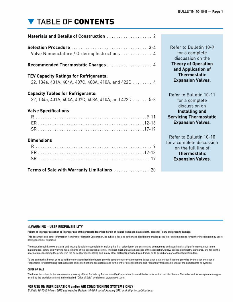
Materials and Details of Construction . . . . . . . . . . . . . . . . . . . 2
Selection Procedure . . . . . . . . . . . . . . . . . . . . . . . . . . . . . . . . .3-4 Valve Nomenclature / Ordering Instructions . . . . . . . . . . . . . 4
Recommended Thermostatic Charges . . . . . . . . . . . . . . . . . . . 4
TEV Capacity Ratings for Refrigerants: 22, 134a, 401A, 404A, 407C, 408A, 410A, and 422D . . . . . . . . 4
Capacity Tables for Refrigerants: 22, 134a, 401A, 404A, 407C, 408A, 410A, and 422D . . . . . . .5-8
Valve Specifications R . . . . . . . . . . . . . . . . . . . . . . . . . . . . . . . . . . . . . . . . . . . . . . .9-11 ER . . . . . . . . . . . . . . . . . . . . . . . . . . . . . . . . . . . . . . . . . . . . .12-16 SR . . . . . . . . . . . . . . . . . . . . . . . . . . . . . . . . . . . . . . . . . . . . .17-19
Dimensions R . . . . . . . . . . . . . . . . . . . . . . . . . . . . . . . . . . . . . . . . . . . . . . . . . 9 ER . . . . . . . . . . . . . . . . . . . . . . . . . . . . . . . . . . . . . . . . . . . . .12-13 SR . . . . . . . . . . . . . . . . . . . . . . . . . . . . . . . . . . . . . . . . . . . . . . . 17
Terms of Sale with Warranty Limitations . . . . . . . . . . . . . . . 20
▼ TABLE OF CONTENTS
Refer to Bulletin 10-9for a complete
discussion on theTheory of Operation and Application of
ThermostaticExpansion Valves .
Refer to Bulletin 10-11for a completediscussion onInstalling and
Servicing ThermostaticExpansion Valves .
Refer to Bulletin 10-10 for a complete discussion
on the full line of Thermostatic
Expansion Valves .

Page 2 — BULLETIN 10-10-8
The Sporlan Type R Valve family features balanced port design, an external adjustment assembly and the replaceable element assembly. The Type R with extended copper connec-tions has recently been expanded to include three conventional body styles, the R, ER, and SR plus new fractional capacity versions.
The ER with extended copper connections provides excep-tional control in both flow directions making the ER an excellent choice for bi-flow heat pump applications. The ER also features the 60 x 50 mesh stainless steel wire cloth inlet strainer as a standard feature; the 100 mesh inlet strainer is an optional feature available for 5/8” ODF and larger fitting combinations.
The Type ER is available in two body sizes. The small body provides capacities up to 8 tons R-22 and R-410A, up to 5 tons R-134a, and up to 6 tons R-404A. Large body ER valves extend capacities to 12 tons R-22 and 15 tons R-410A.
The Sporlan Type R, with SAE flare connections, and the Type SR with the removable strainer assembly share the same balanced port construction as the ER. The R is complete with the 100 mesh inlet strainer as an integral part of the fitting while the SR has a 100 mesh removable strainer that can be cleaned or replaced while the valve remains soldered to the system tubing. These valves are ideally suited for small to large capacity refrigeration applications that could oper-ate over widely varying operating conditions for refrigerants including R-22, R-134a, R-404A, and R-410A.
Type R valves may be applied in bi-directional applications.
Outlet Connections3/8 SAE, 1/2” SAE, 3/8” ODF, 1/2” ODF, 5/8” ODF, 7/8” ODF, 1-1/8” ODF
Mating Distributors (See Bulletin 20-10)D260, D262, 1620, 1622, 1112, 1113, 1115, 1116, 1603, 1605, 1606, 1608, 1650(R), 1651(R), 1653(R), 1655(R)
Flare Connections Extended Solder ConnectionsExtended Solder Connections with
Forged Inlet and Replaceable Strainer
TYPE ERODF(Internally Equalized)
TYPE EREODF(Externally Equalized)
TYPE RSAE(Internally Equalized)
TYPE RESAE(Externally Equalized)
TYPE SREODF(Externally Equalized)
TYPE SRODF(Internally Equalized)
▼ TYPE R, ER, SR
VALVETYPE BODY SEAT PIN PIN
CARRIER PUSHROD(S) TYPE OF JOINTS CONNECTIONS INLET
STRAINER
R Machined Brass Bar Brass Stainless
Steel Brass StainlessSteel
Knife Edgeto Metal
SAE Flare FittingsSilver Soldered to Body Removable
StrainerScreen
ER Machined Brass Bar Brass Stainless
Steel Brass StainlessSteel
Knife Edgeto Metal
ODF Copper FittingsSilver Soldered to Body
SR Machined Brass Bar Brass Stainless
Steel Brass StainlessSteel
Knife Edgeto Metal
Extended Copper FittingsSilver Soldered to Body
InsertStrainer
MATERIALS & DETAILS OF CONSTRUCTION

BULLETIN 10-10-8 — Page 3
REFRIGERANTLIQUID TEMPERATURE ENTERING TEV °F40 50 60 70 80 90 100 110 120 130 140CORRECTION FACTOR, CF LIQUID TEMPERATURE
410A 1.39 1.31 1.23 1.17 1.12 1.06 1.00 0.94 0.88 0.82 0.76
EVAPORATOR TEMPERATURE
°F
PRESSURE DROP ACROSS TEV (psi)
80 120 160 200 240 280 320 360
CORRECTION FACTOR, CF PRESSURE DROP
40° 0.71 0.87 1.00 1.12 1.22 1.32 1.41 1.50
20° & 0° 0.63 0.77 0.89 1.00 1.10 1.18 1.26 1.34
▼AIR CONDITIONING and HEAT PUMP APPLICATIO
THERMOSTATIC EXPANSION VALVE
CAPACITIES for REFRIGERANTS - TONS
VALVE TYPES
NOMINAL CAPACITY
REFRIGERANT410A
RECOMMENDED THERMOSTATIC CHARGE
ZCP 200, ZGA
EVAPORATOR TEMPERATURE °F
40° 20° 0°
ER 1/3 0.51 0.56 0.49
ER 1/2 0.73 0.79 0.71
ER 1 1.19 1.30 1.16
ER 1 1/2 2.08 2.27 2.03
ER 2 2.73 2.99 2.67
ER 3 3.80 4.16 3.72
ER 4 4.99 5.46 4.88
▼ SELECTION PROCEDURE
The following procedure should be used when selecting a Sporlan TEV:1. Determine the liquid temperature of the refrigerant
entering the valve. The TEV capacity tables on pages 5-8 are based on a liquid
temperature of 100°F (38°C) for R-22, R-134a, R-401A, R-404A, R-407C, R-408A, R-409A, R-410A, and R-422D. For other liquid temperatures, apply the correction factor given in the tables for each refrigerant. For example see Table B.
2. Determine pressure drop across valve. The pressure drop correction factors are based on standard
liquid temperature and pressure drop. The standard pres-sure drop is dependent on the evaporator temperature. To determine the pressure drop, subtract the saturated pressure equivalent to evaporator temperature from the condensing pressure. The condensing pressure used in this calculation should be the minimum operating condensing pressure of the system. From this value, subtract all other pressure losses to obtain the net pressure drop across the valve. Use this value to determine the pressure drop correction factor. For example see Table C. Be sure to consider all of the fol-lowing possible sources of pressure drop:
1. Friction losses through refrigeration lines including the evaporator and condenser.
2. Pressure drop across liquid line accessories such as a solenoid valve and filter-drier.
3. Static pressure loss (gain) due to the vertical lift (drop) of the liquid line.
4. Pressure drop across a refrigerant distributor if used. Refer to Bulletin 20-10 for information on refrigerant distributors.3. Select valve from the capacity tables. Select a valve based on the design evaporating temperature.
If possible, the valve capacity should be equal or slightly exceed the design rating of the system. Be sure to apply the appropriate correction factors for liquid temperature and pressure drop. Once the desired valve capacity has been located, determine the nominal capacity of the valve from the table’s second column. On multiple evaporator systems, select each valve on the basis of individual evaporator capacity. For example see Table A.
4. Determine if an external equalizer is required. The amount of pressure drop between the valve outlet and
bulb location will determine if an external equalizer is required. Refer to Bulletin 10-9 for further information on this subject.
5. Select body type. Select the body type according to the style connections
desired. For complete specifications on each TEV type including nominal ratings, refer to pages 9-19.
6. Select the Sporlan Selective Thermostatic Charge. Select the charge according to the design evaporating tem-
perature from the Table on page 4. Refer to Bulletin 10-9 for a complete discussion of the available Sporlan Selective Thermostatic Charges.
Selection Example – Refrigerant 410A Application: air conditioning Design evaporator temperature 40°F 5°C Design condenser temperature 100°F 38°C Refrigerant liquid temperature 90°F 30°C Design system capacity 2 ton 7 kW Available pressure drop across TEV: Condensing pressure - psig / bar 317 22.00 Evaporating pressure - psig / bar 119 8.36 198 13.64
Liquid line and accessories loss - psi / bar – 8 0.58 Distributor and tubes loss - psi / bar Q – 30 2.06 160 11.00
Refrigerant liquid correction factor 1.06 1.15 Pressure drop correction factor 1.00 1.00
Use the following formula to calculate TEV capacity: TEV Capacity = TEV rating x CF liquid temperature x CF pressure drop
ERZE-2 has valve capacity of: 2.73 (9.38) x 1.06 (1.15) x 1.00 (1.00) = 2.89 tons (10.8 kW) at 40°F (30°C) evaporating temperature, 160 psi (11 bar) pressure drop and 90°F (30°C) liquid temperature.
Thermostatic charge (from table on page 4): ZGA W
Selection: ERZE-2-GA 3/8” x 1/2” x 1/4” ODF - 5’ Q An externally equalized valve must be used on evapo-
rators employing a refrigerant distributor due to the pressure drop created by the distributor. In addition, an externally equalized valve should always be used with air conditioning thermostatic charges to reduce the possibil-ity of thermostatic charge migration.
W Please note that the refrigerant charge designation in the thermostatic charge (“Z” in this case) is dropped when it is incorporated into the valve model designation.
Table B
Liquid Temperature
Table C
TEV Pressure Drop
Table A
Design EvaporatingTemperature
The valve capacity should equal or slightly exceed the tonnage rating of the system. (For com-plete R-410A capacity tables, see page 8.)

Page 4 — BULLETIN 10-10-8
▼ SELECTION PROCEDURE
VALVE NOmENCLATURE ExAmPLE / ORDERING INSTRUCTIONS
ER Z E – 2 – GA 3/8” ODFSOLDER x 1/2” ODF
SOLDER x 1/4” ODFSOLDER - 5’
Valve TypeR, ER, SRInternally Equalized
RE, ERE, SREExternally Equalized
Sporlan Code – RefrigerantElement Label Color Code
“E” specifies external
equalizer. Omission of
letter “E” indicates valve with
internal equalizer.
e.g. ERV-1-C
Nominal Capacity in Tons
Ther
mos
tatic
Cha
rge
Inlet Connection
Size and Style
Outlet Connection
Size and Style
External Equalizer
Connection
Size and Style
Capillary Tubing Length
Inches, Feet or Meters
F = R-12 YellowE = R-13 BlueV = R-22 GreenG = R-23 BlueM = R-124 BlueJ = R-134a BlueX = R-401A PinkL = R-402A SandS = R-404A Orange
V = R-407A GreenN = R-407C Lt. BrownS = R-408A PurpleF = R-409A YellowZ = R-410A RoseV = R-422D GreenR = R-502 PurpleW = R-503 BlueP = R-507 TealW = R-508B Blue
RECOmmENDED THERmOSTATIC CHARGES*
APPLICATIONREFRIGERANT ACTUAL
THERMOSTATIC CHARGES
12,409A
22, 422D,407A 410A 134a 401A 404A,
408A 407C 502 507
Air Conditioning
FCP60 – – JCP60 XCP60 – – – – JCP60– VCP100 – – – – NCP100 – – VCP100– – ZCP180 – – – – – – ZCP180– VGA – – – – NGA – – VGA– – – – – – – RCP115 – SCP115– – ZGA – – – – – – ZGA
Commercial Refrigeration 50°F to -10°F
10°C to -23.3°C
FC – – JC XC – – – – JC– VC – – – – NC – – VC– – – – – SC – RC – SC– – – – – – – – PC PC
Low Temperature Refrigeration0°F to -40°F
-17.8°C to -40°C
FZ – – – – – – – – JZFZP – – – – – – – – JZP
– VZ – – – – – – – VZ– VZP40 – – – – – – – VZP40– – – – – SZ – RZ PZ SZ– – – – – SZP – RZP PZP SZP
*APPLICATION FACTORS:1. The Type ZP charges have essentially the same characteristics as the Type Z charge with one exception: they produce a pressure limit Maximum Operating Pressure (MOP). ZP charges are not
intended as replacements for Z charges. Each should be selected for its own unique purpose.2. All air conditioning and heat pump charges are intended for use with externally equalized valves.3. If in doubt as to which charge to use, review the section on thermostatic charges in Bulletin 10-9 or contact Sporlan Division of Parker, Washington, Missouri with complete system data.4. For dual temperature applications, use the “C” charge.5. The “C” charge may be used on applications down to -30°F on R-22, R-404A and R-507.
SPORLAN SELECTIVE CHARGES ENGINEERED for PEAK PERFORMANCE for EACH SPECIFIC APPLICATION
▼ TEV CAPACITY RATINGSTEV capacity ratings for R-22, R-134a, R-401A, R-404A, R-407C, R-408A, R-410A, and R-422D are based on vapor free 100°F (37.8°C) liquid refrigerant entering the expan-sion valve, a maximum opening superheat of 7°F (4K), and a standard factory air test superheat setting. A discussion of the relationship between valve capacities and superheat settings can be found in Bulletin 10-9.
The ratings for evaporator temperatures 40°F, 20°F, -10°F, -40°F (5°C, -5°C, -20°C, -40°C) in the capacity tables are in accordance with ANSI/ARI Standard Number 750. TEVs are tested in accordance with ANSI/ASHRAE 17.
For TEV capacity ratings at operating conditions not shown in the following tables, contact Sporlan Division of Parker.

BULLETIN 10-10-8 — Page 5
▼ CAPACITIES
AIR CONDITIONING / HEAT PUMP and COMMERCIAL REFRIGERATION APPLICATIONS
22, 422D, 407C
VALVE TYPES
NOMINAL CAPACITY
(Ton)
REFRIGERANT22 422DQ 407C
RECOMMENDED THERMOSTATIC CHARGEVC, VCP100, VGA VZ, VZP40 VC, VCP100, VGA VZ, VZP40 NC, NCP100, NGA
EVAPORATOR TEMPERATURE °F40° 20° 0° -10° -20° -40° 40° 20° 0° -10° -20° -40° 40° 20° 0°
R-ER-SR 1/3 0.43 0.47 0.41 0.34 0.30 0.22 0.31 0.33 0.28 0.22 0.20 0.14 0.39 0.42 0.37R-ER-SR 1/2 0.61 0.67 0.60 0.55 0.49 0.37 0.44 0.46 0.40 0.33 0.29 0.21 0.56 0.60 0.53R-ER-SR 1 1.00 1.09 0.97 0.86 0.77 0.57 0.71 0.76 0.66 0.53 0.47 0.34 0.91 0.98 0.86
R-ER 1-1/2 1.75 1.91 1.71 1.22 1.09 0.81 1.25 1.32 1.15 0.93 0.82 0.59 1.59 1.71 1.51R-ER-SR 2 2.30 2.51 2.24 1.60 1.43 1.07 1.64 1.74 1.51 1.22 1.07 0.77 2.09 2.25 1.99R-ER-SR 3 3.21 3.49 3.12 2.30 2.06 1.53 2.28 2.42 2.10 1.70 1.49 1.08 2.91 3.13 2.77
R-ER 4 4.21 4.58 4.09 3.00 2.69 2.00 2.99 3.17 2.75 2.23 1.96 1.41 3.81 4.11 3.63R-ER-SR 5 5.01 5.45 4.87 3.43 3.07 2.29 3.56 3.78 3.27 2.65 2.33 1.68 4.54 4.89 4.32
R-ER 6 6.01 6.54 5.28 3.80 3.18 2.34 4.28 4.53 3.54 2.87 2.53 1.82 5.45 5.87 4.68ER 8 8.01 8.73 7.80 4.40 3.68 2.71 5.70 6.04 5.24 4.24 3.73 2.69 7.26 7.83 6.92ER 10 10.4 11.4 10.2 – – – 7.44 7.88 6.83 – – – 9.47 10.2 9.02ER 12 12.1 13.2 11.8 – – – 8.62 9.14 7.92 – – – 11.0 11.8 10.5
VALVE TYPES
VALVESIZE
NOMINAL CAPACITY
(kW)
REFRIGERANT22 422DQ 407C
RECOMMENDED THERMOSTATIC CHARGEVC, VCP100, VGA VZ, VZP40 VC, VCP100, VGA VZ, VZP40 NC, NCP100, NGA
EVAPORATOR TEMPERATURE °C10° 5° -5° -15° -20° -30° -40° 10° 5° -5° -15° -20° -30° -40° 10° 5° -5° -15° -20°
R-ER-SR 1/3 1.2 1.16 1.15 1.12 1.01 0.87 0.63 0.45 0.74 0.72 0.79 0.69 0.66 0.45 0.34 1.04 1.02 1.14 1.01 0.97R-ER-SR 1/2 1.75 1.99 1.96 1.92 1.73 1.50 1.08 0.77 1.27 1.24 1.36 1.18 1.12 0.78 0.58 1.78 1.75 1.95 1.73 1.66R-ER-SR 1 3.5 3.31 3.28 3.20 2.94 2.63 1.99 1.42 2.12 2.07 2.26 2.00 1.97 1.44 1.07 2.97 2.92 3.25 2.93 2.91
R-ER 1-1/2 5.3 5.80 5.74 5.61 5.14 4.29 2.83 2.01 3.71 3.62 3.96 3.51 3.22 2.04 1.52 5.21 5.12 5.69 5.13 4.75R-ER-SR 2 7 7.62 7.54 7.37 6.75 5.64 3.71 2.64 4.87 4.75 5.20 4.61 4.23 2.67 2.00 6.84 6.72 7.48 6.74 6.24R-ER-SR 3 11 10.6 10.5 10.3 9.40 7.92 5.33 3.80 6.78 6.61 7.24 6.42 5.94 3.84 2.87 9.52 9.35 10.4 9.38 8.77
R-ER 4 14 13.9 13.8 13.5 12.3 10.4 6.95 4.95 8.89 8.68 9.50 8.42 7.78 5.01 3.74 12.5 12.3 13.7 12.3 11.5R-ER-SR 5 18 16.6 16.4 16.0 14.7 12.2 7.95 5.66 10.6 10.3 11.3 10.0 9.15 5.73 4.28 14.9 14.6 16.3 14.7 13.5
R-ER 6 21 19.9 19.7 19.2 16.4 13.3 8.21 5.79 12.7 12.4 13.6 11.2 10.0 2.92 4.38 17.8 17.5 19.5 16.3 14.7ER 8 28 26.5 26.2 25.6 23.5 18.3 9.51 6.70 16.9 16.5 18.1 16.0 13.8 6.86 4.63 23.8 23.4 26.0 23.4 20.3ER 10 35 34.5 34.2 33.4 30.6 17.7 – – 22.1 21.5 23.6 20.9 13.3 – – 31.0 30.5 33.9 30.6 19.6ER 12 42 40.1 39.7 28.8 35.5 20.6 – – 25.6 25.0 27.4 24.3 15.4 – – 36.0 35.4 39.3 35.5 22.8
REFRIGERANTLIQUID TEMPERATURE ENTERING TEV °F
0° 10° 20° 30° 40° 50° 60° 70° 80° 90° 100° 110° 120° 130° 140°CORRECTION FACTOR, CF LIQUID TEMPERATURE
22 1.56 1.51 1.45 1.40 1.34 1.29 1.23 1.17 1.12 1.06 1.00 0.94 0.88 0.82 0.76422D 1.99 1.90 1.80 1.70 1.60 1.50 1.41 1.31 1.20 1.10 1.00 0.90 0.79 0.68 0.57407C 1.69 1.62 1.55 1.49 1.42 1.35 1.28 1.21 1.14 1.07 1.00 0.93 0.85 0.77 0.69
REFRIGERANTLIQUID TEMPERATURE ENTERING TEV °C
-10°C 0° 10° 20° 30° 50° 60°CORRECTION FACTOR, CF LIQUID TEMPERATURE
22 1.52 1.42 1.32 1.21 1.11 0.89 0.87422D 1.86 1.68 1.50 1.33 1.14 0.77 0.57407C 1.73 1.59 1.45 1.30 1.15 0.84 0.67
EVAPORATOR TEMPERATURE
°F
PRESSURE DROP ACROSS TEV (psi)30 50 75 100 125 150 175 200 225 250 275 300
CORRECTION FACTOR, CF PRESSURE DROP40° 0.55 0.71 0.87 1.00 1.12 1.22 1.32 1.41 1.50 1.58 1.66 1.73
20° & 0° 0.49 0.63 0.77 0.89 1.00 1.10 1.18 1.26 1.34 1.41 1.48 1.55-10° & -20° 0.45 0.58 0.71 0.82 0.91 1.00 1.08 1.15 1.22 1.29 1.35 1.41
-40° 0.41 0.53 0.65 0.76 0.85 0.93 1.00 1.07 1.13 1.20 1.25 1.31
EVAPORATOR TEMPERATURE
°C
PRESSURE DROP ACROSS TEV (bar)2 4 6 8 10 12 14 16
CORRECTION FACTOR, CF PRESSURE DROP5° & 10° 0.58 0.82 1.00 1.15 1.29 1.41 1.53 1.63
-5° & -15° 0.50 0.71 0.87 1.00 1.12 1.22 1.32 1.41-20° & -30° 0.45 0.63 0.77 0.89 1.00 1.11 1.18 1.26
-40° 0.41 0.58 0.71 0.82 0.91 1.00 1.08 1.15
These factors include corrections for liquid refrigerant density and net refrigerating effect and are based on an evaporator temperature of 0°F. However, they may be used for any evaporator temperature from -40°F to 40°F since the variation in the actual factors across this range is insignificant.
These factors include corrections for liquid refrigerant density and net refriger-ating effect and are based on an evaporator temperature of -17.8°C. However, they may be used for any evaporator temperature from -40°C to 10°C since the variation in the actual factors across this range is insignificant.
TEV Capacity = TEV Rating x CF Liquid Temperature x CF Pressure Drop — Example: Actual capacity of a nominal 2 ton R-22 Type R valve at 20°F evaporator, 100 psi pressure drop across the TEV, and 90°F liquid temperature entering the TEV = 2.51 (from rating chart) x 1.06 (CF liquid temperature) x 0.89 (CF pressure drop) = 2.37 tons.
TEV Capacity = TEV Rating x CF Liquid Temperature x CF Pressure Drop — Example: Actual capacity of a nominal 7 kW R-22 Type R valve at -5°C evaporator, 6 bar pressure drop across the TEV, and 30°C liquid temperature entering the TEV = 7.37 (from rating chart) x 1.11 (CF liquid temperature) x 0.71 (CF pressure drop) = 5.81 kW.
Q R-422D can be used in a system with R-22 valves, but the TEV capacity will be reduced. Please verify valve capacity will handle system load.
Q R-422D can be used in a system with R-22 valves, but the TEV capacity will be reduced. Please verify valve capacity will handle system load.
TONS ■ psi ■ °F
kW ■ bar ■ °C

AIR CONDITIONING / HEAT PUMP and COMMERCIAL REFRIGERATION APPLICATIONS
VALVE TYPES
NOMINAL CAPACITY
(Tons)
REFRIGERANT134a 401A 409A
RECOMMENDED THERMOSTATIC CHARGEJC, JCP60 XC, XCP60 FC, FCP60
EVAPORATOR TEMPERATURE °F40° 20° 0° 40° 20° 0° 40° 20° 0°
ER-SR 1/6 0.31 0.35 0.30 0.33 0.36 0.31 0.31 0.36 0.31R-ER-SR 1/4 0.44 0.49 0.43 0.46 0.51 0.45 0.44 0.50 0.44R-ER-SR 1/2 0.72 0.80 0.70 0.75 0.84 0.74 0.72 0.82 0.73R-ER-SR 1 1.27 1.40 1.23 1.32 1.47 1.30 1.27 1.44 1.27R-ER-SR 1-1/2 1.67 1.84 1.61 1.73 1.93 1.71 1.67 1.89 1.67R-ER-SR 2 2.32 2.56 2.24 2.41 2.68 2.37 2.32 2.63 2.32R-ER-SR 3 3.62 4.00 3.50 3.77 4.19 3.71 3.62 4.10 3.63
ER 4 4.35 4.80 3.79 4.52 5.03 4.01 4.35 4.92 3.93ER 5 5.79 6.39 5.60 6.02 6.71 5.93 5.80 6.56 5.80
VALVE TYPES
VALVESIZE
NOMINAL CAPACITY
(kW)
REFRIGERANT134a 401A 409A
RECOMMENDED THERMOSTATIC CHARGEJC, JCP60 XC, XCP60 FC, FCP60
EVAPORATOR TEMPERATURE °C10° 5° -5° -15° 10° 5° -5° -15° 10° 5° -5° -15°
ER-SR 1/6 0.6 0.86 0.85 1.00 0.95 0.93 0.91 1.08 1.04 0.87 0.85 1.04 1.01R-ER-SR 1/4 0.9 1.48 1.45 1.70 1.63 1.59 1.56 1.84 1.78 1.49 1.46 1.80 1.73R-ER-SR 1/2 1.8 2.49 2.44 2.86 2.57 2.67 2.62 3.10 2.81 2.50 2.45 2.90 2.62R-ER-SR 1 3.5 4.35 4.27 5.01 4.50 4.66 4.59 5.42 2.83 4.37 4.29 5.07 4.58R-ER-SR 1-1/2 5.3 5.72 5.61 6.58 5.91 6.13 6.03 7.12 6.47 5.74 5.64 6.66 6.02R-ER-SR 2 7 7.96 7.80 9.16 8.23 8.53 8.39 9.91 8.99 7.99 7.85 9.27 8.37R-ER-SR 3 8.8 10.4 10.2 12.0 10.8 11.2 11.0 13.1 11.8 10.5 10.3 12.2 11.0
ER 4 11 12.4 12.2 14.3 12.9 13.3 13.1 15.5 14.1 12.5 12.3 14.5 13.1ER 5 14 14.9 14.6 17.2 14.3 16.0 15.7 18.6 15.7 15.0 14.7 17.4 14.6
These factors include corrections for liquid refrigerant density and net refrigerating effect and are based on an evaporator temperature of 0°F. However, they may be used for any evaporator temperature from 0°F to 40°F since the variation in the actual factors across this range is insignificant.
These factors include corrections for liquid refrigerant density and net refriger-ating effect and are based on an evaporator temperature of -17.8°C. However, they may be used for any evaporator temperature from -15°C to 10°C since the variation in the actual factors across this range is insignificant.
TEV Capacity = TEV Rating x CF Liquid Temperature x CF Pressure Drop — Example: Actual capacity of a nominal 2 ton R-134a Type R valve at 20°F evaporator, 60 psi pressure drop across the TEV, and 60°F liquid temperature entering the TEV = 2.56 (from rating chart) x 1.36 (CF liquid temperature) x 0.87 (CF pressure drop) = 3.03 tons.
TEV Capacity = TEV Rating x CF Liquid Temperature x CF Pressure Drop — Example: Actual capacity of a nominal 7 kW R-134a Type R valve at -5°C evaporator, 4 bar pressure drop across the TEV, and 10°C liquid temperature entering the TEV = 9.16 (from rating chart) x 1.39 (CF liquid temperature) x 0.82 (CF pressure drop) = 10.4 kW.
REFRIGERANTLIQUID TEMPERATURE ENTERING TEV °F
0° 10° 20° 30° 40° 50° 60° 70° 80° 90° 100° 110° 120° 130° 140°CORRECTION FACTOR, CF LIQUID TEMPERATURE
134a 1.70 1.63 1.56 1.49 1.42 1.36 1.29 1.21 1.14 1.07 1.00 0.93 0.85 0.78 0.71401A 1.60 1.54 1.48 1.43 1.36 1.31 1.25 1.19 1.13 1.06 1.00 0.94 0.87 0.80 0.74409A 1.55 1.50 1.45 1.39 1.34 1.28 1.23 1.17 1.12 1.06 1.00 0.94 0.88 0.82 0.76
REFRIGERANTLIQUID TEMPERATURE ENTERING TEV °C
-10° 0° 10° 20° 30° 40° 50° 60°CORRECTION FACTOR, CF LIQUID TEMPERATURE
134a 1.64 1.52 1.39 1.26 1.13 1.00 0.87 0.73401A 1.52 1.42 1.31 1.20 1.09 0.98 0.86 0.74409A 1.51 1.41 1.31 1.21 1.11 1.00 0.89 0.78
EVAPORATOR TEMPERATURE
°F
PRESSURE DROP ACROSS TEV (psi)20 40 60 80 100 120 140 160CORRECTION FACTOR, CF PRESSURE DROP
40° 0.58 0.82 1.00 1.15 1.29 1.41 1.53 1.6320° & 0° 0.50 0.71 0.87 1.00 1.12 1.22 1.32 1.41
EVAPORATOR TEMPERATURE
°C
PRESSURE DROP ACROSS TEV (bar)2 4 6 8 10 12
CORRECTION FACTOR, CF PRESSURE DROP5° & 10° 0.71 1.00 1.22 1.41 1.58 1.73
-5° & -15° 0.58 0.82 1.00 1.15 1.29 1.41
134a, 401A, 409A▼ CAPACITIES
TONS ■ psi ■ °F
kW ■ bar ■ °C
Page 6 — BULLETIN 10-10-8

BULLETIN 10-10-8 — Page 7
AIR CONDITIONING / HEAT PUMP and COMMERCIAL REFRIGERATION APPLICATIONS
▼ CAPACITIES
TONS ■ psi ■ °F
kW ■ bar ■ °C
404A, 408A
These factors include corrections for liquid refrigerant density and net refrigerating effect and are based on an evaporator temperature of 0°F. However, they may be used for any evaporator temperature from -40°F to 40°F since the variation in the actual factors across this range is insignificant.
These factors include corrections for liquid refrigerant density and net refriger-ating effect and are based on an evaporator temperature of -17.8°C. However, they may be used for any evaporator temperature from -40°C to 5°C since the variation in the actual factors across this range is insignificant.
TEV Capacity = TEV Rating x CF Liquid Temperature x CF Pressure Drop — Example: Actual capacity of a nominal 2 ton R-404A Type R valve at -20°F evaporator, 125 psi pressure drop across the TEV, and 60°F liquid temperature entering the TEV = 2.06 (from rating chart) x 1.43 (CF liquid temperature) x 0.91(CF pressure drop) = 2.68 tons.
TEV Capacity = TEV Rating x CF Liquid Temperature x CF Pressure Drop — Example: Actual capacity of a nominal 7 kW R-404A Type R valve at -30°C evaporator, 8 bar pressure drop across the TEV, and 20°C liquid temperature entering the TEV = 3.87 (from rating chart) x 1.37 (CF liquid temperature) x 0.89 (CF pressure drop) = 4.72 kW.
VALVE TYPES
NOMINAL CAPACITY
(Tons)
REFRIGERANT404A 408A
RECOMMENDED THERMOSTATIC CHARGESC, SCP115 SZ, SZP SC, SCP115 SZ, SZP
EVAPORATOR TEMPERATURE °F40° 20° 0° -10° -20° -40° 40° 20° 0° -10° -20° -40°
ER-SR 1/6 0.27 0.29 0.25 0.34 0.30 0.22 0.35 0.38 0.33 0.27 0.24 0.17R-ER-SR 1/4 0.39 0.41 0.36 0.55 0.49 0.37 0.50 0.54 0.48 0.43 0.39 0.28R-ER-SR 1/2 0.63 0.67 0.58 0.86 0.77 0.57 0.81 0.88 0.78 0.68 0.60 0.44R-ER-SR 1 1.10 1.17 1.02 1.22 1.09 0.81 1.42 1.54 1.36 0.96 0.86 0.63R-ER-SR 1-1/2 1.45 1.54 1.33 1.60 1.43 1.07 1.87 2.02 1.78 1.26 1.13 0.83R-ER-SR 2 2.02 2.14 1.86 2.30 2.06 1.53 2.60 2.81 2.48 1.82 1.62 1.19R-ER-SR 3 2.65 2.81 2.44 3.00 2.69 2.00 3.42 3.69 3.26 2.37 2.11 1.55
ER 4 3.78 4.01 3.14 3.80 3.18 2.34 4.88 5.27 4.20 3.00 2.50 1.81ER 6 5.04 5.35 4.64 4.40 3.68 2.71 6.51 7.02 6.20 3.48 2.89 2.10
VALVE TYPES
VALVESIZE
NOMINAL CAPACITY
(kW)
REFRIGERANT404A 408A
RECOMMENDED THERMOSTATIC CHARGESC, SCP115 SZ, SZP SC, SCP115 SZ, SZP
EVAPORATOR TEMPERATURE °C5° -5° -15° -20° -30° -40° 5° -5° -15° -20° -30° -40°
ER-SR 1/6 0.6 0.71 0.78 0.74 0.80 0.66 0.57 0.91 1.02 0.99 1.08 0.91 0.8R-ER-SR 1/4 0.9 1.21 1.34 1.27 1.35 1.07 0.85 1.57 1.75 1.69 1.81 1.47 1.18R-ER-SR 1/2 1.8 1.88 2.07 1.85 1.88 1.45 1.09 2.43 2.71 2.46 2.52 1.99 1.53R-ER-SR 1 3.5 3.57 3.94 3.51 3.23 2.06 1.55 4.61 5.15 4.67 4.33 2.82 2.17R-ER-SR 1-1/2 5.3 4.70 5.18 4.61 4.23 2.68 2.01 6.06 6.77 6.14 5.68 3.67 2.82R-ER-SR 2 7 6.52 7.18 6.40 5.94 3.87 2.91 8.40 9.39 8.51 7.98 5.30 4.08R-ER-SR 3 11 8.58 9.45 8.42 7.81 5.06 3.80 11.1 12.4 11.2 10.5 6.93 5.33
ER 4 14 12.3 13.5 11.2 10.1 6.06 4.51 15.8 17.7 14.9 13.5 8.30 6.32ER 6 21 16.3 18.0 16.0 13.8 6.92 5.15 21.1 23.5 21.3 18.5 9.48 7.22
REFRIGERANTLIQUID TEMPERATURE ENTERING TEV °F
0° 10° 20° 30° 40° 50° 60° 70° 80° 90° 100° 110° 120° 130° 140°CORRECTION FACTOR, CF LIQUID TEMPERATURE
404A 2.04 1.94 1.84 1.74 1.64 1.54 1.43 1.33 1.22 1.11 1.00 0.89 0.77 0.65 0.53408A 1.66 1.60 1.54 1.47 1.40 1.34 1.27 1.21 1.14 1.07 1.00 0.93 0.86 0.79 0.71
REFRIGERANTLIQUID TEMPERATURE ENTERING TEV °C
-10° 0° 10° 20° 30° 40° 50° 60°CORRECTION FACTOR, CF LIQUID TEMPERATURE
404A 1.89 1.72 1.56 1.37 1.19 1.00 0.79 0.56408A 1.58 1.46 1.34 1.22 1.10 0.97 0.85 0.71
EVAPORATOR TEMPERATURE
°F
PRESSURE DROP ACROSS TEV (psi)30 50 75 100 125 150 175 200 225 250 275
CORRECTION FACTOR, CF PRESSURE DROP40° 0.55 0.71 0.87 1.00 1.12 1.22 1.32 1.41 1.50 1.58 1.66
20° & 0° 0.49 0.63 0.77 0.89 1.00 1.10 1.18 1.26 1.34 1.41 1.48-10° & -20° 0.45 0.58 0.71 0.82 0.91 1.00 1.08 1.15 1.22 1.29 1.35
-40° 0.41 0.53 0.65 0.76 0.85 0.93 1.00 1.07 1.13 1.20 1.25
EVAPORATOR TEMPERATURE
°C
PRESSURE DROP ACROSS TEV (bar)2 4 6 8 10 12 14 16
CORRECTION FACTOR, CF PRESSURE DROP5° 0.58 0.82 1.00 1.15 1.29 1.41 1.53 1.63
-5° & -15° 0.50 0.71 0.87 1.00 1.12 1.22 1.32 1.41-20° & -30° 0.45 0.63 0.77 0.89 1.00 1.10 1.18 1.26
-40° 0.41 0.58 0.71 0.82 0.91 1.00 1.08 1.15

Page 8 — BULLETIN 10-10-8
VALVE TYPES
NOMINAL CAPACITY
(Tons)
REFRIGERANT410A
RECOMMENDED THERMOSTATIC CHARGEZCP180, ZGA
EVAPORATOR TEMPERATURE °F40° 20° 0°
ER 1 1.19 1.30 1.16ER 1-1/2 2.08 2.27 2.03ER 2 2.73 2.99 2.67ER 3 3.80 4.16 3.72ER 4 4.99 5.46 4.88ER 5 5.94 6.50 5.81ER 6 7.13 7.79 6.29ER 8 9.50 10.4 9.29ER 12-1/2 12.4 13.5 12.1ER 15 14.4 15.7 14.1
VALVE TYPES
VALVESIZE
NOMINAL CAPACITY
(kW)
REFRIGERANT410A
RECOMMENDED THERMOSTATIC CHARGEZCP180, ZGA
EVAPORATOR TEMPERATURE °C10° 5° -5° -15°
ER 1 3.5 4.12 4.08 4.50 4.12ER 1-1/2 5.3 7.21 7.14 7.88 7.21ER 2 7 9.47 9.38 10.4 9.48ER 3 11 13.2 13.1 14.4 13.2ER 4 14 17.3 17.1 18.9 17.3ER 5 18 20.6 20.4 22.5 20.6ER 6 21 24.7 24.5 27.0 23.0ER 8 28 33.0 32.6 36.0 33.0ER 10 44 43.0 42.5 46.9 43.0ER 15 53 49.8 49.4 54.4 49.9
These factors include corrections for liquid refrigerant density and net refriger-ating effect and are based on an evaporator temperature of 0°F. However, they may be used for any evaporator temperature from 0°F to 40°F since the varia-tion in the actual factors across this range is insignificant.
These factors include corrections for liquid refrigerant density and net refriger-ating effect and are based on an evaporator temperature of -17.8°C. However, they may be used for any evaporator temperature from -15°C to 10°C since the variation in the actual factors across this range is insignificant.
TEV Capacity = TEV Rating x CF Liquid Temperature x CF Pressure Drop — Example: Actual capacity of a nominal 2 ton R-410A Type R valve at 20°F evapo-rator, 160 psi pressure drop across the TEV, and 90°F liquid temperature enter-ing the TEV = 2.99 (from rating chart) x 1.06 (CF liquid temperature) x 0.89 (CF pressure drop) = 2.82 tons.
TEV Capacity = TEV Rating x CF Liquid Temperature x CF Pressure Drop — Example: Actual capacity of a nominal 7 kW R-410A Type R valve at -5°C evapo-rator, 11 bar pressure drop across the TEV, and 30°C liquid temperature entering the TEV = 10.4 (from rating chart) x 1.15 (CF liquid temperature) x 0.89 (CF pres-sure drop) = 10.6 kW.
REFRIGERANTLIQUID TEMPERATURE ENTERING TEV °F
40 50 60 70 80 90 100 110 120 130 140CORRECTION FACTOR, CF LIQUID TEMPERATURE
410A 1.39 1.31 1.23 1.17 1.12 1.06 1.00 0.94 0.88 0.82 0.76
REFRIGERANTLIQUID TEMPERATURE ENTERING TEV °C
20° 30° 40° 50° 60°CORRECTION FACTOR, CF LIQUID TEMPERATURE
410A 1.30 1.15 1.00 0.84 0.65
EVAPORATOR TEMPERATURE
°F
PRESSURE DROP ACROSS TEV (psi)80 120 160 200 240 280 320 360
CORRECTION FACTOR, CF PRESSURE DROP40° 0.71 0.87 1.00 1.12 1.22 1.32 1.41 1.50
20° & 0° 0.63 0.77 0.89 1.00 1.10 1.18 1.26 1.34
EVAPORATOR TEMPERATURE
°C
PRESSURE DROP ACROSS TEV (bar)8 11 14 17 20
CORRECTION FACTOR, CF PRESSURE DROP5° & 10° 0.85 1.00 1.13 1.24 1.35
-5° & -15° 0.76 0.89 1.00 1.10 1.20
410A
AIR CONDITIONING / HEAT PUMP
▼ CAPACITIES
TONS ■ psi ■ °F
kW ■ bar ■ °C

BULLETIN 10-10-8 — Page 9
▼ TYPE R For Refrigerants 22, 134a, 404A, 507SAE Flare Connections
FEATURES• Small brass body• Replaceable thermostatic element with gray epoxy coating• SAE Flare connections in a variety of common sizes• 100 mesh inlet strainer integral to fitting• Available in single lot or case quantities• Option for 15% bleed port
(Other bleed port rates available with OEM version only)
Outlet Connections - SAE3/8”, 1/2”
Mating Distributors (See Bulletin 20-10)1603, 1605, 1606, 1608, 1650(R)
SPECIFICATIONS• Operating Temperature Range: -40°F (-40°C) through 50°F (10°C)• Maximum Ambient Temperature: 140°F (60°C)• Maximum Rated Pressure (UL): 450 psig (31 bar)• Maximum Low Side Test Pressure: 450 psig (31 bar)• Agency Certifications: UL Recognized under file SA5410.
Covered under CE and the PED (Pressure Equipment Directive)
For complete details of construction, see page 2.
Type R
REFRIGERANTTHERMOSTATIC CHARGE
C Z GA P TYPE,ZP SERIES
12, 134a 190°F88°C
250°F121°C – 250°F
121°C
22, 407C 160°F71°C
185°F85°C
250°F121°C
250°F121°C
404A, 502, 507 150°F66°C
170°F77°C – 250°F
121°C
MAXIMUM DEHYDRATION and BULB TEMPERATURE
DImENSIONS - TYPE RE with NUMBER 43 ELEMENT
1.94”49.3 mm
A B
3.53”89.7 mm
2.17”55.1 mm
1.83”46.5 mm
C
1/4 SAE Inlet Strainer - P/N 3008-0003/8 SAE Inlet Strainer - P/N 1538-000
60°
1.54”39.1 mm
External 1/4 SAEEqualizer Fitting
Top View CONNECTIONS
FITTING SIZEInches
Inches mm
A B C A B CInlet Outlet
1/4 3/8 1.09 1.63 1.13 27.7 41.4 28.7
3/8 1/2 1.27 1.82 0.71 38.1 46.2 18.0
BULB SIZES
REFR
IGER
AN
T
STA
ND
ARD
CHA
RGE BULB
DIMENSION
REPL
ACE
MEN
T
PART NUMBER
CAPILLARYTUBE LENGTH
Inches mm 30”760 mm
60”1500 mm
R-404AR-408AR-502
C
0.50 ODx
3.00
12.7 ODx
76.2
KT-43-SC 179943 180204
R-402AR-507 C KT-43-PC 180288 180338
R-402AR-404AR-408AR-502R-507
Z KT-43-SZ 180228 180318
ZP KT-43-SZP 180230 180060
R-22R-407CR-422D
C KT-43-VC 180269 180319
R-134aR-401AR-409A
C KT-43-JC 180314 180310
Type RE
Page 10 — BULLETIN 10-10-8
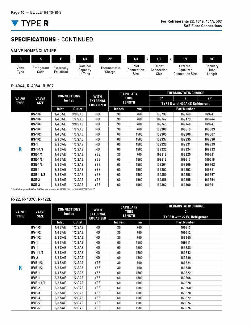
▼ TYPE R For Refrigerants 22, 134a, 404A, 507SAE Flare Connections
VALVE NOMENCLATURE
R S E – 1/4 – ZP – 1/4 x 1/2 x 1/4 – 30”
ValveType
Refrigerant Code
Externally Equalized
Nominal Capacityin Tons
Thermostatic Charge
InletConnection
Size
OutletConnection
Size
ExternalEqualizer
Connection Size
CapillaryTube
Length
VALVETYPE
VALVESIZE
CONNECTIONS Inches
WITHEXTERNAL EQUALIZER
CAPILLARYTUBE
LENGTH
THERMOSTATIC CHARGE
C* Z ZP
TYPE R with 404A (S) RefrigerantInlet Outlet Inches mm Part Number
R
RS-1/6 1/4 SAE 3/8 SAE NO 30 760 169739 169740 169741RS-1/6 1/4 SAE 1/2 SAE NO 30 760 169742 169473 169744RS-1/4 1/4 SAE 3/8 SAE NO 30 760 169745 169746 169747RS-1/4 1/4 SAE 1/2 SAE NO 30 760 169308 169310 169309RS-1/2 1/4 SAE 1/2 SAE NO 60 1500 169305 169306 169307RS-1/2 3/8 SAE 1/2 SAE NO 60 1500 169337 169335 169336RS-1 3/8 SAE 1/2 SAE NO 60 1500 169330 169331 169329RS-1-1/2 3/8 SAE 1/2 SAE NO 60 1500 169332 169334 169333RSE-1/4 1/4 SAE 1/2 SAE YES 30 760 169319 169320 169321RSE-1/2 1/4 SAE 1/2 SAE YES 60 1500 169318 169317 169316RSE-1/2 3/8 SAE 1/2 SAE YES 60 1500 169364 169365 169363RSE-1 3/8 SAE 1/2 SAE YES 60 1500 169352 169353 169351RSE-1-1/2 3/8 SAE 1/2 SAE YES 60 1500 169359 169358 169357RSE-2 3/8 SAE 1/2 SAE YES 60 1500 169356 169355 169354RSE-3 3/8 SAE 1/2 SAE YES 60 1500 169362 169360 169361
R-404A, R-408A, R-507
VALVETYPE
VALVESIZE
CONNECTIONS Inches
WITHEXTERNAL EQUALIZER
CAPILLARYTUBE
LENGTH
THERMOSTATIC CHARGE
C
TYPE R with 22 (V) RefrigerantInlet Outlet Inches mm Part Number
R
RV-1/3 1/4 SAE 1/2 SAE NO 30 760 169313RV-1/2 1/4 SAE 1/2 SAE NO 30 760 169312RV-1/2 3/8 SAE 1/2 SAE NO 30 760 169345RV-1 1/4 SAE 1/2 SAE NO 60 1500 169311RV-1 3/8 SAE 1/2 SAE NO 60 1500 169338RV-1-1/2 3/8 SAE 1/2 SAE NO 60 1500 169342RV-2 3/8 SAE 1/2 SAE NO 60 1500 169340RVE-1/3 1/4 SAE 1/2 SAE YES 30 760 169324RVE-1/2 3/8 SAE 1/2 SAE YES 30 760 169380RVE-1 1/4 SAE 1/2 SAE YES 60 1500 169322RVE-1 3/8 SAE 1/2 SAE YES 60 1500 169366RVE-1-1/2 3/8 SAE 1/2 SAE YES 60 1500 169378RVE-2 3/8 SAE 1/2 SAE YES 60 1500 169368RVE-3 3/8 SAE 1/2 SAE YES 60 1500 169370RVE-4 3/8 SAE 1/2 SAE YES 60 1500 169372RVE-5 3/8 SAE 1/2 SAE YES 60 1500 169374RVE-6 3/8 SAE 1/2 SAE YES 60 1500 169376
R-22, R-407C, R-422D
SPECIFICATIONS - CONTINUED
* For C charge on R-507 or R-402A, use element kit 180288 (30”) or 180338 (60”) KT-43-PC.

BULLETIN 10-10-8 — Page 11
▼ TYPE R
SPECIFICATIONS - CONTINUED
VALVETYPE
VALVESIZE
CONNECTIONSInches
WITHEXTERNAL EQUALIZER
CAPILLARYTUBE
LENGTH
THERMOSTATIC CHARGE
C
TYPE R with 134a (J) Refrigerant
Inlet Outlet Inches mm Part Number
R
RJ-1/6 1/4 SAE 3/8 ODF NO 30 760 169737RJ-1/6 1/4 SAE 1/2 ODF NO 30 760 169738RJ-1/4 1/4 SAE 3/8 SAE NO 30 760 169298RJ-1/4 1/4 SAE 1/2 SAE NO 30 760 169302RJ-1/4 3/8 SAE 1/2 SAE NO 30 760 169328RJ-1/2 1/4 SAE 3/8 SAE NO 60 1500 169297RJ-1/2 1/4 SAE 1/2 SAE NO 60 1500 169299RJ-1/2 3/8 SAE 1/2 SAE NO 60 1500 169327RJ-1 3/8 SAE 1/2 SAE NO 60 1500 169325RJ-1-1/2 3/8 SAE 1/2 SAE NO 60 1500 169326RJ-1-1/2 1/4 SAE 1/2 SAE YES 30 760 169315RJE-1/2 1/4 SAE 1/2 SAE YES 60 1500 169314RJE-1/2 3/8 SAE 1/2 SAE YES 60 1500 169350RJE-1 3/8 SAE 1/2 SAE YES 60 1500 169346RJE-1-1/2 3/8 SAE 1/2 SAE YES 60 1500 169349RJE-2 3/8 SAE 1/2 SAE YES 60 1500 166347RJE-3 3/8 SAE 1/2 SAE YES 60 1500 169348
R-134a, R-401A, R-409A
For Refrigerants 22, 134a, 404A, 507SAE Flare Connections

FEATURES• Small brass body• Replaceable thermostatic element with gray epoxy coating• Internally and externally equalized versions available• Two body sizes:
Small - For capacities less than 8 tons R-22, 6 tons R-404A, 5 tons R-134a and 8 tons R-410A Large - For capacities 10 to12 tons R-22, 12-1/2 to15 tons R-410A
• ODF connections in a variety of common sizes• Inlet strainer available• Available in single lot or case quantities• Option for 15% bleed port
(Other bleed port rates available with OEM version only)
Outlet Connections - ODF3/8”, 1/2”, 5/8”, 7/8”, 1-1/8”
Mating Distributors (See Bulletin 20-10)D260, D262, 1620, 1622, 1112, 1113, 1115, 1116, 1651(R), 1653(R), 1655(R)
▼ TYPE ER For Refrigerants 22, 134a, 404A, 410A, 507ODF Solder Connections
Type ER
REFRIGERANTTHERMOSTATIC CHARGE
C Z GA P TYPE,ZP SERIES
12, 134a 190°F88°C
250°F121°C – 250°F
121°C
22, 407C 160°F71°C
185°F85°C
250°F121°C
250°F121°C
404A, 502, 507 150°F66°C
170°F77°C – 250°F
121°C
410A – – 250°F*121°C*
250°F*121°C*
MAXIMUM DEHYDRATION and BULB TEMPERATURE
DImENSIONS - TYPE ERE (SMALL BODY) with NUMBER 43 and 45 ELEMENT
Type ERE
3.53”89.7 mm
1.94”49.3 mm
A B
2.17”55.1 mm 1.83”
46.5 mm
C
E
D
Cap Tube 60”
F
1/4 ODF Insert Strainer - P/N 1543-0023/8 ODF Insert Strainer - P/N 1524-000
CONNECTIONS
FITTING SIZEInches
Inches mm
A B C D E F A B C D E FInlet Outlet1/4 3/8 1.69 2.42 0.31 0.31 .253/.256 .377/.381 42.9 61.5 7.87 7.87 6.43/6.50 9.58/9.683/8 1/2 2.42 2.51 0.31 0.40 .377/.381 .502/.506 61.5 63.8 7.90 10.2 9.58/9.68 12.8/12.9
1/2 5/8 2.35 2.51 0.40 0.50 .502/.506 .627/.632 59.7 63.8 10.2 12.7 12.8/12.9 15.9/16.17/8 2.41 0.78 .877/.882 61.2 19.8 22.3/22.4
5/8 2.35 0.50 .627/.632 59.7 12.7 15.9/16.11-1/8 2.41 0.91 1.128/1.135 61.2 23.1 28.7
.253/.256”6.43/6.50 mm
Diameter1.94”49.3 mm
0.31”7.9 mm
1.81”50.0 mm
30°Top View
* Bulb temperature can not exceed 160°F (71°C).
Page 12 — BULLETIN 10-10-8
SPECIFICATIONS• Operating Temperature Range: -40°F (-40°C) through 50°F (10°C)• Maximum Ambient Temperature: 140°F (60°C)• Maximum Rated Pressure (UL): 450 psig (31 bar)
700 psig (48.3 bar) for R-410A Only• Maximum Low Side Test Pressure: 450 psig (31 bar)
700 psig (48.3 bar) for R-410A Only• Agency Certifications: UL Recognized under file SA5410.
Covered under CE and the PED (Pressure Equipment Directive)
For complete details of construction, see page 2.

BULLETIN 10-10-8 — Page 13
▼ TYPE ER
SPECIFICATIONS - CONTINUED
DImENSIONS - TYPE ERE (LARGE BODY) with NUMBER 45-5 ELEMENT
C
Cap Tube 60”
D
1.94”49.3 mm
1.83”46.5 mm
F
A B
2.30”58.4 mm
E3.79”
96.3 mm
CONNECTIONS
.253/.256”6.43/6.50 mm
Diameter1.94”49.3 mm
1.90“48.3 mm
0.31“7.9 mm
30°
Top View
FITTING SIZEInches
Inches mm
A B C D E F A B C D E FInlet Outlet
5/87/8
2.48 2.51 0.500.78
.627/.632.877/.882
63.0 63.8 12.719.8
15.9/16.122.3/22.4
1-1/8 0.91 1.128/1.135 23.1 28.7/28.8
For Refrigerants 22, 134a, 404A, 410A, 507ODF Solder Connections
BULB SIZES
REFR
IGER
AN
T
STA
ND
ARD
CHA
RGE BULB
DIMENSIONREPLACEMENT
PART NUMBER
CAPILLARYTUBE LENGTH
Inches mm 30”760 mm
60”1500 mm
R-404AR-408AR-502
C
0.50 OD x 3.00 12.7 OD x 76.2
KT-43-SC 179943 180204
R-402AR-507 C KT-43-PC 180288 180338
R-402AR-404AR-408AR-502R-507
Z KT-43-SZ 180228 180318
ZP KT-43-SZP 180230 180060
R-22R-407CR-422D
C KT-43-VC 180269 180319CP100 KT-43-VCP100 180270 180272
GA 0.75 OD x 2.00 19.5 OD x 50.8 KT-43-VGA 180284 180276
R-134aR-401AR-409A
C0.50 OD x 3.00 12.7 OD x 76.2
KT-43-JC 180314 180310
CP60 KT-43-JCP60 180206 180312
R-410AZGA 0.75 OD x 2.00 19.5 OD x 50.8
KT-45-ZGA 181209 181212KT-45-5-ZGA — 180298
ZCP180 0.50 OD x 3.00 12.7 OD x 76.2KT-45-ZCP180 181355 181213KT-45-5-ZCP180 — 181216

Page 14 — BULLETIN 10-10-8
▼ TYPE ER
SPECIFICATIONS - CONTINUED
VALVE NOMENCLATURE
ER Z E – 1 – GA – 3/8 x 1/2 x 1/4 – 60”
ValveType
Refrigerant Code
Externally Equalized
Nominal Capacityin Tons
Thermostatic Charge
InletConnection
Size
OutletConnection
Size
ExternalEqualizer
Connection Size
CapillaryTube
Length
For Refrigerants 22, 134a, 404A, 410A, 507ODF Solder Connections
VALVETYPE
VALVESIZE
CONNECTIONSInches STRAINER
INCLUDED
WITHEXTERNAL EQUALIZER
CAPILLARYTUBE
LENGTH
THERMOSTATIC CHARGE
C CP100 GA
TYPE R with 22 (V) RefrigerantInlet Outlet Inches mm Part Number
ER
ERV-1/3 1/4 ODF 3/8 ODF YES NO 30 760 169159 — —ERV-1/3 1/4 ODF 1/2 ODF YES NO 30 760 169173 — —ERV-1/3 3/8 ODF 1/2 ODF YES NO 30 760 169209 — —ERV-1/2 1/4 ODF 3/8 ODF YES NO 30 760 169158 — —ERV-1/2 1/4 ODF 1/2 ODF YES NO 30 760 169172 — —ERV-1/2 3/8 ODF 1/2 ODF YES NO 30 760 169208 — —ERV-1 3/8 ODF 1/2 ODF YES NO 60 1500 169206 — —ERV-2 3/8 ODF 1/2 ODF YES NO 60 1500 169207 — —ERVE-1/3 1/4 ODF 1/2 ODF YES YES 30 760 169187 — —ERVE-1/2 1/4 ODF 1/2 ODF YES YES 30 760 169186 — —ERVE-1/2 3/8 ODF 1/2 ODF YES YES 30 760 169246 — —ERVE-1 1/4 ODF 1/2 ODF YES YES 60 1500 169185 — —ERVE-1 3/8 ODF 1/2 ODF YES YES 60 1500 169230 168796 168798ERVE-1-1/2 3/8 ODF 1/2 ODF YES YES 60 1500 169243 168742 168743ERVE-2 3/8 ODF 1/2 ODF YES YES 60 1500 169231 168744 168745ERVE-3 3/8 ODF 1/2 ODF YES YES 60 1500 169234 168746 168748ERVE-3 1/2 ODF 5/8 ODF NO YES 60 1500 169265 168747 168749ERVE-4 3/8 ODF 1/2 ODF YES YES 60 1500 169238 168750 168753ERVE-4 1/2 ODF 5/8 ODF NO YES 60 1500 169268 168751 168754ERVE-4 1/2 ODF 7/8 ODF NO YES 60 1500 169282 168752 168755ERVE-5 3/8 ODF 1/2 ODF YES YES 60 1500 169241 168756 168759ERVE-5 1/2 ODF 5/8 ODF NO YES 60 1500 169271 168757 168760ERVE-5 1/2 ODF 7/8 ODF NO YES 60 1500 169283 168758 168761ERVE-6 1/2 ODF 5/8 ODF NO YES 60 1500 169274 168762 168766ERVE-6 1/2 ODF 7/8 ODF NO YES 60 1500 169284 168763 168767ERVE-6 5/8 ODF 7/8 ODF NO YES 60 1500 169293 168764 168768ERVE-8 1/2 ODF 7/8 ODF NO YES 60 1500 — 168769 168772ERVE-8 5/8 ODF 7/8 ODF NO YES 60 1500 169294 168770 168773ERVE-8 5/8 ODF 1-1/8 ODF NO YES 60 1500 — 168771 168774ERVE-10 5/8 ODF 7/8 ODF NO YES 60 1500 169295 168775 168777ERVE-10 5/8 ODF 1-1/8 ODF NO YES 60 1500 — 168776 168778ERVE-12 5/8 ODF 7/8 ODF NO YES 60 1500 169296 168779 168781ERVE-12 5/8 ODF 1-1/8 ODF NO YES 60 1500 — 168780 168782
R-22, R-407C, R-422D

BULLETIN 10-10-8 — Page 15
▼ TYPE ER For Refrigerants 22, 134a, 404A, 410A, 507ODF Solder Connections
SPECIFICATIONS - CONTINUED
VALVETYPE
VALVESIZE
CONNECTIONSInches STRAINER
INCLUDED
WITHEXTERNAL EQUALIZER
CAPILLARYTUBE
LENGTH
THERMOSTATIC CHARGE
C* Z ZP
TYPE R with 404A (S) RefrigerantInlet Outlet Inches mm Part Number
ER
ERS-1/6 1/4 ODF 3/8 ODF YES NO 30 760 169155 169156 169157ERS-1/6 1/4 ODF 1/2 ODF YES NO 30 760 169169 169170 169171ERS-1/6 3/8 ODF 1/2 ODF YES NO 30 760 169203 169204 169205ERS-1/4 1/4 ODF 3/8 ODF YES NO 30 760 169152 169153 169154ERS-1/4 1/4 ODF 1/2 ODF YES NO 30 760 169166 169167 169168ERS-1/4 3/8 ODF 1/2 ODF YES NO 30 760 169200 169201 169202ERS-1/2 1/4 ODF 3/8 ODF YES NO 60 1500 169149 169150 169151ERS-1/2 1/4 ODF 1/2 ODF YES NO 60 1500 169163 169165 169164ERS-1/2 3/8 ODF 1/2 ODF YES NO 60 1500 169198 169197 169199ERS-1 3/8 ODF 1/2 ODF YES NO 60 1500 169191 169192 169193ERS-1-1/2 3/8 ODF 1/2 ODF YES NO 60 1500 169195 169196 169194ERSE-1/6 1/4 ODF 1/2 ODF YES YES 30 760 169184 — —ERSE-1/4 1/4 ODF 1/2 ODF YES YES 30 760 169181 169183 169182ERSE-1/2 1/4 ODF 1/2 ODF YES YES 60 1500 169178 169180 169179ERSE-1/2 3/8 ODF 1/2 ODF YES YES 60 1500 169228 169229 169227ERSE-1 1/4 ODF 1/2 ODF YES YES 60 1500 169177 169176 —ERSE-1 3/8 ODF 1/2 ODF YES YES 60 1500 169216 169217 169215ERSE-1-1/2 3/8 ODF 1/2 ODF YES YES 60 1500 169224 169223 169222ERSE-2 3/8 ODF 1/2 ODF YES YES 60 1500 169219 169220 169218ERSE-3 3/8 ODF 1/2 ODF YES YES 60 1500 169226 169221 169225ERSE-3 1/2 ODF 5/8 ODF NO YES 60 1500 169260 169261 169262ERSE-4 1/2 ODF 7/8 ODF NO YES 60 1500 169278 169280 169279ERSE-6 5/8 ODF 7/8 ODF NO YES 60 1500 169287 169288 169289
R-404A, R-408A, R-507
* For C charge on R-507 or R-402A, use element kit 180288 (30”) or 180338 (60”) KT-43-PC.

For Refrigerants 22, 134a, 404A, 410A, 507ODF Solder Connections▼ TYPE ER
SPECIFICATIONS - CONTINUED
R-410A
VALVETYPE
VALVESIZE
CONNECTIONSInches STRAINER
INCLUDED
WITHEXTERNAL EQUALIZER
CAPILLARYTUBE
LENGTH
THERMOSTATIC CHARGE
CP180 GA
TYPE R with 410A (Z) Refrigerant
Inlet Outlet Inches mm Part Number
ER
ERZE-1 3/8 ODF 1/2 ODF YES YES 60 1500 168878 168790ERZE-1-1/2 3/8 ODF 1/2 ODF YES YES 60 1500 168783 168784ERZE-2 3/8 ODF 1/2 ODF YES YES 60 1500 168737 168786ERZE-3 3/8 ODF 1/2 ODF YES YES 60 1500 168787 168788ERZE-4 3/8 ODF 1/2 ODF YES YES 60 1500 168789 168718ERZE-5 3/8 ODF 1/2 ODF YES YES 60 1500 168791 168792ERZE-6 1/2 ODF 5/8 ODF NO YES 60 1500 168793 168794ERZE-8 1/2 ODF 7/8 ODF NO YES 60 1500 168795 168797ERZE-8 5/8 ODF 7/8 ODF NO YES 60 1500 168736 168719ERZE-12-1/2 5/8 ODF 7/8 ODF NO YES 60 1500 168799 168801ERZE-12-1/2 5/8 ODF 1-1/8 ODF NO YES 60 1500 168800 168802ERZE-15 5/8 ODF 7/8 ODF NO YES 60 1500 168803 168720ERZE-15 5/8 ODF 1-1/8 ODF NO YES 60 1500 168804 168807
VALVETYPE
VALVESIZE
CONNECTIONSInches STRAINER
INCLUDED
WITHEXTERNAL EQUALIZER
CAPILLARYTUBE
LENGTH
THERMOSTATIC CHARGE
C CP60
TYPE R with 134a (J) Refrigerant
Inlet Outlet Inches mm Part Number
ER
ERJ-1/6 1/4 ODF 1/2 ODF YES NO 30 760 169162 —ERJ-1/4 1/4 ODF 3/8 ODF YES NO 30 760 169147 —ERJ-1/4 1/4 ODF 1/2 ODF YES NO 30 760 169161 —ERJ-1/2 1/4 ODF 3/8 ODF YES NO 60 1500 169146 —ERJ-1/2 1/4 ODF 1/2 ODF YES NO 60 1500 169160 —ERJ-1/2 3/8 ODF 1/2 ODF YES NO 60 1500 169190 —ERJ-1 3/8 ODF 1/2 ODF YES NO 60 1500 169188 —ERJ-1-1/2 3/8 ODF 1/2 ODF YES NO 60 1500 169189 —ERJE-1/4 3/8 ODF 1/2 ODF YES YES 30 760 169175 —ERJE-1/2 1/4 ODF 1/2 ODF YES YES 60 1500 169174 —ERJE-1/2 3/8 ODF 1/2 ODF YES YES 60 1500 169214 —ERJE-1 3/8 ODF 1/2 ODF YES YES 60 1500 169210 —ERJE-1-1/2 3/8 ODF 1/2 ODF YES YES 60 1500 169213 —ERJE-2 3/8 ODF 1/2 ODF YES YES 60 1500 169211 —ERJE-2 1/2 ODF 5/8 ODF NO YES 60 1500 — 169257ERJE-3 3/8 ODF 1/2 ODF YES YES 60 1500 169212 —ERJE-3 1/2 ODF 5/8 ODF NO YES 60 1500 — 169258ERJE-4 1/2 ODF 5/8 ODF NO YES 60 1500 — 169259ERJE-4 1/2 ODF 7/8 ODF NO YES 60 1500 — 169277ERJE-5 5/8 ODF 7/8 ODF NO YES 60 1500 — 169285
R-134a, R-401A, R-409A
Page 16 — BULLETIN 10-10-8

BULLETIN 10-10-8 — Page 17
▼ TYPE SR For Refrigerants 22, 134a, 404A, 507 ODF Solder Connections
FEATURES• Small brass body• Replaceable thermostatic element with gray epoxy coating• Externally adjustable• Balanced port construction• Internally and externally equalized versions available• Available with extended ODF fittings• 100 mesh removable strainer, can be cleaned or replaced without
removing the valve from the system• Available in single lot or case quantities• Option for 15% bleed port
(Other bleed port rates available with OEM version only)
Outlet Connections - ODF1/2”
Mating Distributors (See Bulletin 20-10)D260, D262
SPECIFICATIONS• Operating Temperature Range: -40°F (-40°C) through 50°F (10°C)• Maximum Ambient Temperature: 140°F (60°C)• Maximum Rated Pressure (UL): 450 psig (31 bar)• Maximum Low Side Test Pressure: 450 psig (31 bar)• Agency Certifications: UL Recognized under file SA5410.
Covered under CE and the PED (Pressure Equipment Directive)
For complete details of construction, see page 2.
REFRIGERANTTHERMOSTATIC CHARGE
C Z P TYPE,ZP SERIES
12, 134a 190°F88°C
250°F121°C
250°F121°C
22, 407C 160°F71°C
185°F85°C
250°F121°C
404A, 502, 507 150°F66°C
170°F77°C
250°F121°C
MAXIMUM DEHYDRATION and BULB TEMPERATURE
DImENSIONS - TYPE SRE with NUMBER 43 ELEMENT
Type SRE
1.94”49.3 mm
1.31”33.3 mm
2.51”63.8 mm
3.53”89.7 mm
2.17”55.1 mm 1.83”
46.5 mm
Removable Strainer - P/N 3427-000
.31
.48
.40
Top View
1.87”47 mm
60°
Type SR
BULB SIZES
REFR
IGER
AN
T
STA
ND
ARD
CHA
RGE
BULBDIMENSION
REPL
ACE
MEN
T
PART NUMBER
Inches mm
CAPILLARYTUBE LENGTH30”
760 mm60”
1500 mmR-404AR-408AR-502
C
0.50 ODx
3.00
12.7x
76.2
KT-43-SC 179943 180204
R-402AR-507 C KT-43-PC 180288 180338
R-402AR-404AR-408AR-502R-507
Z KT-43-SZ 180228 180318
ZP KT-43-SZP 180230 180060
R-22R-407CR-422D
C KT-43-VC 180269 180319
R-134aR-401AR-409A
C KT-43-JC 180314 180310

SPECIFICATIONS - CONTINUED
VALVE NOMENCLATURE
SR S E – 1/6 – ZP – 3/8 x 1/2 x 1/4 – 30”
ValveType
Refrigerant Code
Externally Equalized
Nominal Capacityin Tons
Thermostatic Charge
InletConnection
Size
OutletConnection
Size
ExternalEqualizer
Connection Size
CapillaryTube
Length
VALVETYPE
VALVESIZE
CONNECTIONSInches
WITHEXTERNAL EQUALIZER
CAPILLARYTUBE
LENGTH
THERMOSTATIC CHARGE
C
TYPE R with 22 (V) RefrigerantInlet Outlet Inches mm Part Number
SR
SRV-1/3 3/8 ODF 1/2 ODF NO 60 1500 169405SRV-1/2 3/8 ODF 1/2 ODF NO 60 1500 169404SRV-1 3/8 ODF 1/2 ODF NO 60 1500 169402SRV-2 3/8 ODF 1/2 ODF NO 60 1500 169403SRVE-1/3 3/8 ODF 1/2 ODF YES 30 760 169446SRVE-1/2 3/8 ODF 1/2 ODF YES 30 760 169445SRVE-1 3/8 ODF 1/2 ODF YES 60 1500 169435SRVE-2 3/8 ODF 1/2 ODF YES 60 1500 169438SRVE-3 3/8 ODF 1/2 ODF YES 60 1500 169441SRVE-5 3/8 ODF 1/2 ODF YES 60 1500 169444
R-22, R-407C, R-422D
For Refrigerants 22, 134a, 404A, 507 ODF Solder Connections▼ TYPE SR
VALVETYPE
VALVESIZE
CONNECTIONSInches
WITHEXTERNAL EQUALIZER
CAPILLARYTUBE
LENGTH
THERMOSTATIC CHARGE
C* Z ZP
TYPE R with 404 (S) RefrigerantInlet Outlet Inches mm Part Number
SR
SRS-1-1/2 3/8 ODF 1/2 ODF NO 60 1500 169390 169391 169392SRSE-1/6 3/8 ODF 1/2 ODF YES 30 760 169432 169433 169434SRSE-1/4 3/8 ODF 1/2 ODF YES 30 760 169429 169431 169430SRSE-1/2 3/8 ODF 1/2 ODF YES 60 1500 169426 169427 169428SRSE-1 3/8 ODF 1/2 ODF YES 60 1500 169413 169415 169414SRSE-1-1/2 3/8 ODF 1/2 ODF YES 60 1500 169423 169424 169425SRSE-2 3/8 ODF 1/2 ODF YES 60 1500 169417 169419 169418SRSE-3 3/8 ODF 1/2 ODF YES 60 1500 169420 169422 169421
R-404A, R-408A, R-507
* For C charge on R-507 or R-402A, use element kit 180288 (30”) or 180338 (60”) KT-43-PC.
Page 18 — BULLETIN 10-10-8

BULLETIN 10-10-8 — Page 19
▼ TYPE SR
SPECIFICATIONS - CONTINUED
VALVETYPE
VALVESIZE
CONNECTIONSInches
WITHEXTERNAL EQUALIZER
CAPILLARYTUBE
LENGTH
THERMOSTATIC CHARGE
C
TYPE R with 134a (J) Refrigerant
Inlet Outlet Inches mm Part Number
SR
SRJ-1/6 3/8 ODF 1/2 ODF NO 30 760 169386SRJ-1/4 3/8 ODF 1/2 ODF NO 30 760 169385SRJ-1/2 3/8 ODF 1/2 ODF NO 60 1500 169384SRJ-1 3/8 ODF 1/2 ODF NO 60 1500 169383SRJ-1-1/2 3/8 ODF 1/2 ODF NO 60 1500 169382SRJE-1/6 3/8 ODF 1/2 ODF YES 30 760 169410SRJE-1/4 3/8 ODF 1/2 ODF YES 30 760 169411SRJE-1 3/8 ODF 1/2 ODF YES 60 1500 169412SRJE-1/2 3/8 ODF 1/2 ODF YES 60 1500 169408SRJE-1-1/2 3/8 ODF 1/2 ODF YES 60 1500 169409SRJE-2 3/8 ODF 1/2 ODF YES 60 1500 169406SRJE-3 3/8 ODF 1/2 ODF YES 60 1500 169407
R-134a, R-401A, R-409A
For Refrigerants 22, 134a, 404A, 507 ODF Solder Connections

Page 20 — BULLETIN 10-10-8
OFFER OF SALE
The items described in this document and other documents and descriptions provided by Parker Hannifin Corporation, its subsidiaries and its authorized distributors (“Seller”) are hereby offered for sale at prices to be established by Seller. This offer and its acceptance by any customer (“Buyer”) shall be governed by all of the following Terms and Conditions. Buyer’s order for any item described in its document, when communicated to Seller verbally, or in writing, shall constitute acceptance of this offer. All goods or work described will be referred to as “Products”.
1. Terms and Conditions. Seller’s willingness to offer Products, or accept an order for Products, to or from Buyer is expressly conditioned on Buyer’s as-sent to these Terms and Conditions and to the terms and conditions found on-line at www.parker.com/saleterms/. Seller objects to any contrary or additional term or condition of Buyer’s order or any other docu-ment issued by Buyer.2. Price Adjustments; Payments. Prices stated on the reverse side or preceding pages of this document are valid for 30 days. After 30 days, Seller may change prices to reflect any increase in its costs resulting from state, federal or local legislation, price increases from its suppliers, or any change in the rate, charge, or classification of any carrier. The prices stated on the reverse or preceding pages of this document do not include any sales, use, or other taxes unless so stated specifically. Unless otherwise specified by Seller, all prices are F.O.B. Seller’s facility, and pay-ment is due 30 days from the date of invoice. After 30 days, Buyer shall pay interest on any unpaid invoices at the rate of 1.5% per month or the maximum allow-able rate under applicable law.3. Delivery Dates; Title and Risk; Shipment. All delivery dates are approximate and Seller shall not be responsible for any damages resulting from any delay. Regardless of the manner of shipment, title to any products and risk of loss or damage shall pass to Buyer upon tender to the carrier at Seller’s facility (i.e., when it’s on the truck, it’s yours). Unless otherwise stated, Seller may exercise its judgment in choosing the carrier and means of delivery. No deferment of shipment at Buyers’ request beyond the respec-tive dates indicated will be made except on terms that will indemnify, defend and hold Seller harmless against all loss and additional expense. Buyer shall be responsible for any additional shipping charges incurred by Seller due to Buyer’s changes in shipping, product specifications or in accordance with Section 13, herein.4. Warranty. Seller warrants that the Products sold hereunder shall be free from defects in material or workmanship for a period of twelve months from the date of delivery to Buyer or 2,000 hours of normal use, whichever occurs first. This warranty is made only to Buyer and does not extend to anyone to whom Products are sold after purchased from Seller. The prices charged for Seller’s products are based upon the exclusive limited warranty stated above, and upon the following disclaimer: DISCLAIMER OF WARRANTY: THIS WARRANTY COMPRISES THE SOLE AND ENTIRE WARRANTY PERTAINING TO PRODUCTS PROVIDED HEREUNDER. SELLER DISCLAIMS ALL OTHER WARRANTIES, EXPRESS AND IMPLIED, INCLUDING MERCHANTABILITY AND FITNESS FOR A PARTICULAR PURPOSE.5. Claims; Commencement of Actions. Buyer shall promptly inspect all Products upon delivery. No claims for shortages will be allowed unless reported to the Seller within 10 days of delivery. No other claims against Seller will be allowed unless asserted in writing within 60 days after delivery or, in the case of an alleged breach of warranty, within 30 days after the date within the warranty period on which the de-fect is or should have been discovered by Buyer. Any action based upon breach of this agreement or upon any other claim arising out of this sale (other than an action by Seller for any amount due to Seller from Buyer) must be commenced within thirteen months from the date of tender of delivery by Seller or, for a cause of action based upon an alleged breach of war-ranty, within thirteen months from the date within the warranty period on which the defect is or should have been discovered by Buyer.6. LIMITATION OF LIABILITY. UPON NOTIFICA-TION, SELLER WILL, AT ITS OPTION, REPAIR OR RE-PLACE A DEFECTIVE PRODUCT, OR REFUND THE PURCHASE PRICE. IN NO EVENT SHALL SELLER BE LIABLE TO BUYER FOR ANY SPECIAL, INDI-RECT, INCIDENTAL OR CONSEQUENTIAL DAM-AGES ARISING OUT OF, OR AS THE RESULT OF, THE SALE, DELIVERY, NON-DELIVERY, SERVIC-ING, USE OR LOSS OF USE OF THE PRODUCTS OR ANY PART THEREOF, OR FOR ANY CHARGES OR EXPENSES OF ANY NATURE INCURRED WITHOUT SELLER’S WRITTEN CONSENT, EVEN
IF SELLER HAS BEEN NEGLIGENT, WHETHER IN CONTRACT, TORT OR OTHER LEGAL THEORY. IN NO EVENT SHALL SELLER’S LIABILITY UNDER ANY CLAIM MADE BY BUYER EXCEED THE PUR-CHASE PRICE OF THE PRODUCTS.7. Contingencies. Seller shall not be liable for any default or delay in performance if caused by circum-stances beyond the reasonable control of Seller.8. User Responsibility. The user, through its own analysis and testing, is solely responsible for making the final selection of the system and Product and as-suring that all performance, endurance, maintenance, safety and warning requirements of the application are met. The user must analyze all aspects of the application and follow applicable industry standards and Product information. If Seller provides Product or system options, the user is responsible for determin-ing that such data and specifications are suitable and sufficient for all applications and reasonably foresee-able uses of the Products or systems.9. Loss to Buyer’s Property. Any designs, tools, patterns, materials, drawings, confidential information or equipment furnished by Buyer or any other items which become Buyer’s property, may be considered obsolete and may be destroyed by Seller after two consecutive years have elapsed without Buyer plac-ing an order for the items which are manufactured using such property. Seller shall not be responsible for any loss or damage to such property while it is in Seller’s possession or control.10. Special Tooling. A tooling charge may be imposed for any special tooling, including without limitation, dies, fixtures, molds and patterns, acquired to manufacture Products. Such special tooling shall be and remain Seller’s property notwithstanding pay-ment of any charges by Buyer. In no event will Buyer acquire any interest in apparatus belonging to Seller which is utilized in the manufacture of the Products, even if such apparatus has been specially converted or adapted for such manufacture and notwithstanding any charges paid by Buyer. Unless otherwise agreed, Seller shall have the right to alter, discard or otherwise dispose of any special tooling or other property in its sole discretion at any time.11. Buyer’s Obligation; Rights of Seller. To secure payment of all sums due or otherwise, Seller shall retain a security interest in the goods delivered and this agreement shall be deemed a Security Agree-ment under the Uniform Commercial Code. Buyer authorizes Seller as its attorney to execute and file on Buyer’s behalf all documents Seller deems necessary to perfect its security interest. Seller shall have a se-curity interest in, and lien upon, any property of Buyer in Seller’s possession as security for the payment of any amounts owed to Seller by Buyer.12. Improper use and Indemnity. Buyer shall indemnify, defend, and hold Seller harmless from any claim, liability, damages, lawsuits, and costs (including attorney fees), whether for personal injury, property damage, patent, trademark or copyright in-fringement or any other claim, brought by or incurred by Buyer, Buyer’s employees, or any other person, arising out of: (a) improper selection, improper ap-plication or other misuse of Products purchased by Buyer from Seller; (b) any act or omission, negligent or otherwise, of Buyer; (c) Seller’s use of patterns, plans, drawings, or specifications furnished by Buyer to manufacture Product; or (d) Buyer’s failure to comply with these terms and conditions. Seller shall not indemnify Buyer under any circumstance except as otherwise provided.13. Cancellations and Changes. Orders shall not be subject to cancellation or change by Buyer for any reason, except with Seller’s written consent and upon terms that will indemnify, defend and hold Seller harmless against all direct, incidental and conse-quential loss or damage. Seller may change product features, specifications, designs and availability with notice to Buyer.14. Limitation on Assignment. Buyer may not assign its rights or obligations under this agreement without the prior written consent of Seller.15. Entire Agreement. This agreement contains the entire agreement between the Buyer and Seller and constitutes the final, complete and exclusive expression of the terms of the agreement. All prior
or contemporaneous written or oral agreements or negotiations with respect to the subject matter are herein merged. 16. Waiver and Severability. Failure to enforce any provision of this agreement will not waive that provi-sion nor will any such failure prejudice Seller’s right to enforce that provision in the future. Invalidation of any provision of this agreement by legislation or other rule of law shall not invalidate any other provision herein. The remaining provisions of this agreement will remain in full force and effect.17. Termination. This agreement may be terminated by Seller for any reason and at any time by giving Buyer thirty (30) days written notice of termination. In addition, Seller may by written notice immediately terminate this agreement for the following: (a) Buyer commits a breach of any provision of this agreement (b) the appointment of a trustee, receiver or custodian for all or any part of Buyer’s property (c) the filing of a petition for relief in bankruptcy of the other Party on its own behalf, or by a third party (d) an assignment for the benefit of creditors, or (e) the dissolution or liquidation of the Buyer.18. Governing Law. This agreement and the sale and delivery of all Products hereunder shall be deemed to have taken place in and shall be governed and construed in accordance with the laws of the State of Ohio, as applicable to contracts executed and wholly performed therein and without regard to conflicts of laws principles. Buyer irrevocably agrees and consents to the exclusive jurisdiction and venue of the courts of Cuyahoga County, Ohio with respect to any dispute, controversy or claim arising out of or relating to this agreement. Disputes between the parties shall not be settled by arbitration unless, after a dispute has arisen, both parties expressly agree in writing to arbitrate the dispute. 19. Indemnity for Infringement of Intellectual Property Rights. Seller shall have no liability for infringement of any patents, trademarks, copyrights, trade dress, trade secrets or similar rights except as provided in this Section. Seller will defend and indem-nify Buyer against allegations of infringement of U.S. patents, U.S. trademarks, copyrights, trade dress and trade secrets (“Intellectual Property Rights”). Seller will defend at its expense and will pay the cost of any settlement or damages awarded in an action brought against Buyer based on an allegation that a Product sold pursuant to this Agreement infringes the Intellec-tual Property Rights of a third party. Seller’s obliga-tion to defend and indemnify Buyer is contingent on Buyer notifying Seller within ten (10) days after Buyer becomes aware of such allegations of infringement, and Seller having sole control over the defense of any allegations or actions including all negotiations for settlement or compromise. If a Product is subject to a claim that it infringes the Intellectual Property Rights of a third party, Seller may, at its sole expense and option, procure for Buyer the right to continue using the Product, replace or modify the Product so as to make it noninfringing, or offer to accept return of the Product and return the purchase price less a reason-able allowance for depreciation. Notwithstanding the foregoing, Seller shall have no liability for claims of infringement based on information provided by Buyer, or directed to Products delivered hereunder for which the designs are specified in whole or part by Buyer, or infringements resulting from the modification, combination or use in a system of any Product sold hereunder. The foregoing provisions of this Section shall constitute Seller’s sole and exclusive liability and Buyer’s sole and exclusive remedy for infringement of Intellectual Property Rights.20. Taxes. Unless otherwise indicated, all prices and charges are exclusive of excise, sales, use, property, occupational or like taxes which may be imposed by any taxing authority upon the manufacture, sale or delivery of Products.21. Equal Opportunity Clause. For the perfor-mance of government contracts and where dollar value of the Products exceed $10,000, the equal employment opportunity clauses in Executive Order 11246, VEVRAA, and 41 C.F.R. §§ 60-1.4(a), 60-741.5(a), and 60-250.4, are hereby incorporated.

32012 / Bulletin 10-10-8© 2012 Parker Hannifin Corporation
Parker Hannifin CorporationSporlan Division206 Lange Drive, Washington, MO 63090 USA phone 636 239 1111 fax 636 239 9130 www.sporlan.com