manufacturing technology 1
TRANSCRIPT

ME 361Manufacturing SciencesJ.Ramkumar
Topics coveredTopics covered
• General introductionGeneral introduction
• Classification of machining process
hi i i h i l d l• Machining with single‐edge tools
• Types of cutting
• Types of chip

Introduction• Manufacturing process to produce
– Specified shape– Material properties
• ProcessChange in configuration and physical properties– Change in configuration and physical properties
• Following type of operations– Constant mass operationsp
• Casting, rolling, extrusion, wire drawing, forging, etc– Material addition operations – Bottom up approach
• Bolting rivetting keying welding rapid prototyping etc• Bolting, rivetting , keying, welding, rapid prototyping, etc– Material removal operations (surplus materials removed) – Top down approach
M hi i fi i hi t• Machining, finishing, etc

Basics of Machining processBasics of Machining process
• Relative motion obtained by combining rotatory and translatory movements of either the tool or workpiece or both
• Shape is obtained by relative motion ofShape is obtained by relative motion of – Shape of the tool– Path it traverses
• Tool path is parallel to the axis cylindrical surface both internal• Tool path is parallel to the axis – cylindrical surface both internal and external
• Tool/workpiece is reciprocated – flat surface – Shaping (tool reciprocates and workpiece feed) and planing (vice versa)
– Other examples• Milling – Surface and end milling• drilling

Basics of Machining process
• Generatix
g p
Ge e at– Lines generated by cutting motion
• Directrix– Lines from feed motion
• How is a taper made ?• Methods of generating surfaces
– Tracing method – direct tracing of the generatrices Eg: shaping, planing
– Generation – surface produced is the envelop of the generatrices – milling etcgeneratrices milling, etc
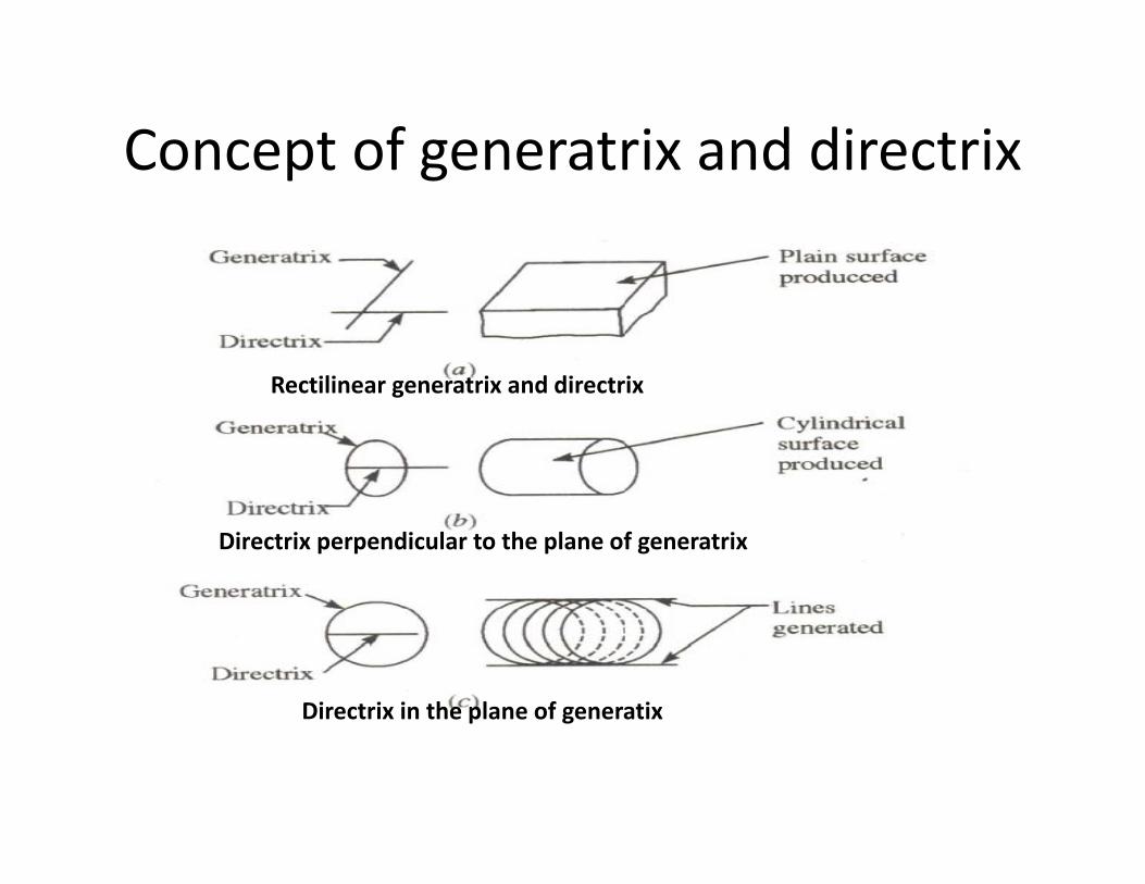
Concept of generatrix and directrixConcept of generatrix and directrix
Rectilinear generatrix and directrixRectilinear generatrix and directrix
Directrix perpendicular to the plane of generatrix
Directrix in the plane of generatixp g

Generation of Various SurfacesGeneration of Various Surfaces
1:

Classification of Machining ProcessClassification of Machining Process
• Surplus material removed in the form of chip• Difference between tool and machine‐tool?
– Machine tool relative motionMachine tool relative motion• Primary – Power• Secondary ‐ feed
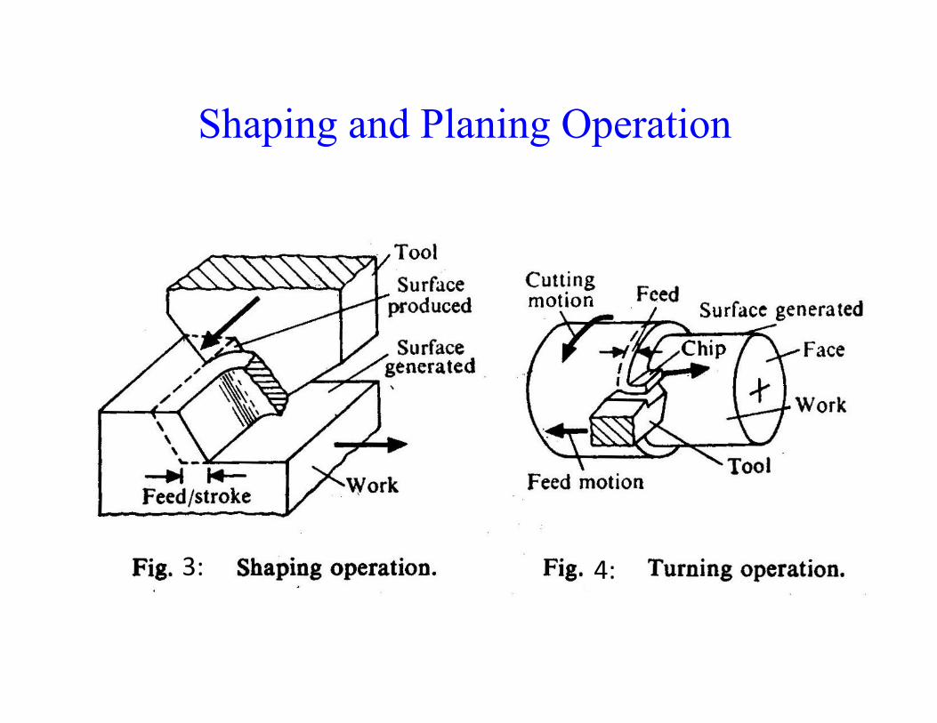
Shaping and Planing OperationShaping and Planing Operation
3: 4:

Turning Operationg p
5:

Milling and Grinding OperationMilling and Grinding Operation
6:

Simulation of Actual Machining Processes
7:
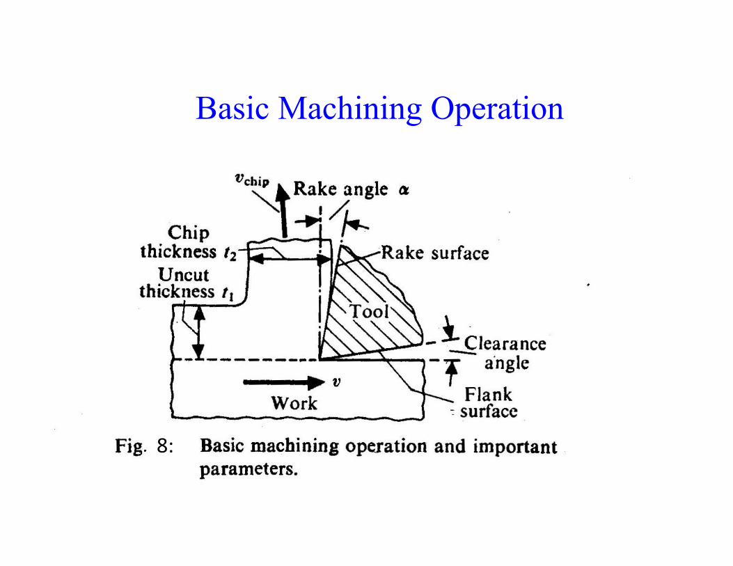
Basic Machining OperationBasic Machining Operation
8:

Machining with Single‐edge toolsMachining with Single edge tools
• Simple toolSimple tool– Principal cutting edge
Auxiliary cutting edge– Auxiliary cutting edge
• Important angles in a wedge shape tool– Rake angle – tool face with a plane normal to cutting velocity vector and the machined surface
Fl k l fl k f d hi d f– Flank angle – flank face and machined surface
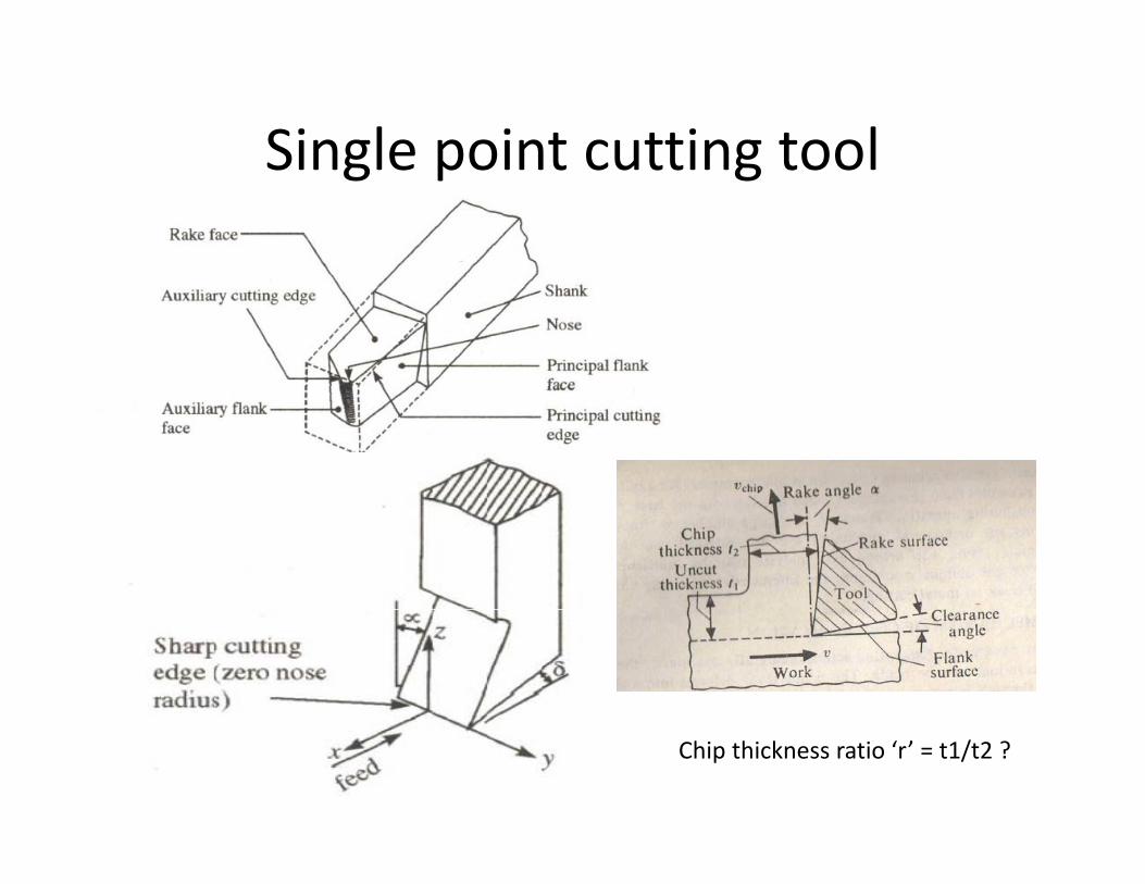
Single point cutting toolSingle point cutting tool
Chip thickness ratio ‘r’ = t1/t2 ?

Types of cuttingTypes of cutting
Wedge shape tool – constrained to relative motion of the workpeice to form a chip.
Orthogonal cutting where i 0 and cutting edge is perpendicular to cutting velocityOrthogonal cutting – where i = 0 and cutting edge is perpendicular to cutting velocityOblique cutting – 3D cutting and i is inclinde
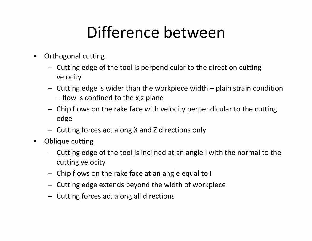
Difference between• Orthogonal cutting
– Cutting edge of the tool is perpendicular to the direction cutting l itvelocity
– Cutting edge is wider than the workpiece width – plain strain condition – flow is confined to the x,z plane
– Chip flows on the rake face with velocity perpendicular to the cutting edge
– Cutting forces act along X and Z directions only
• Oblique cutting
– Cutting edge of the tool is inclined at an angle I with the normal to the cutting velocity
– Chip flows on the rake face at an angle equal to I
– Cutting edge extends beyond the width of workpiece
– Cutting forces act along all directions– Cutting forces act along all directions

Types of chips• Depending upon the work material , cutting conditions, three basic types
•Relative motion between tool and workpiece –compression at cutting edge – plastic state.•Plastic flow on rake surface
• Continuous chip
Plastic flow on rake surface•Shearing action of the work material
• Continuous chip
• Continuous chip with built‐up edge
• Discontinuous chipDiscontinuous chip

Types of chipsTypes of chips• Continuous chip with Built‐up edge
U d t i diti t t d t t l– Under certain conditions temperature and pressure at tool chip interface is high –
– sliding – rupture(strain hardening and thermal softening) from the chip takes placefrom the chip takes place
– High resistance at tool‐chip interface – protecting layer removedAffi it f ldi– Affinity for welding
– Starting growing – build – up edge– Growth is high – unstable – Move along the chip– Move with the machined surface– Forms only at critical speedForms only at critical speed

Types of chipsTypes of chips
Continuous chip,
Continuous chip with built‐up‐edge
Discontinuous chip

Formation of chip and its factorsFormation of chip and its factors

Type of chipsType of chips•speed ‐ recrystalization temperature
• Above recrystal temp – strain‐hardening i l dis neglected• Low recrystal temp – strain hardening is high• Same – BUE is formed

Influence of cutting speed and hRoughness
• Region 1 – Ra is poor discontinuous chip asRegion 1 Ra is poor, discontinuous chip, as speed increases Ra improves from discontinuous to semi discontinuousdiscontinuous to semi discontinuous
• Region 2 – BUE is formed and continuous till recrystalization temperaturerecrystalization temperature
• Region 3 ‐ Continuous chips with out BUE so d Rgood Ra

Tool Geometry• Cutting process is influenced by the inclination of the cutting edgeCutting process is influenced by the inclination of the cutting edge
and orientation of rake and flank face.
• Orientation define we need reference plane and axes.
I k f i li i• Important – rake face inclination
Rake angle can be measured in
• A plane normal to the cutting edge and perpendicular to the plane A plane normal to the cutting edge and perpendicular to the planecontaining cutting edge – OABC
• A plane parallel to the cutting velocity vector and perpendicular to the plane containing the cutting edge ODEFthe plane containing the cutting edge – ODEF
• A plane containing the cutting velocity and chip velocity – ODGH as shown in fig

Single edge cutting toolSingle edge cutting tool
• In oblique cutting, three different values of rake q g,angle is obtained
• They are normal rake, velocity rake and effective rakerake.
• More cutting edges are involved the cutting tool becomes very complexbecomes very complex
• Different system are followed– ASA/Co‐ordinate system– Continental/Orthogonal system ‐ German– Maximum rake system/BritishNormal rake system/International– Normal rake system/International

Reference planes
Reference planes in orthogonal system(1) Longitudinal (2) transfer feed directionsReference planes in co‐ordinate system ( ) g ( )
Third plane is in the direction of theThird plane is in the direction of the Max slope of the rake face
Reference planes in normal rake systems(1) Longitudinal (2) Transverse feed directions
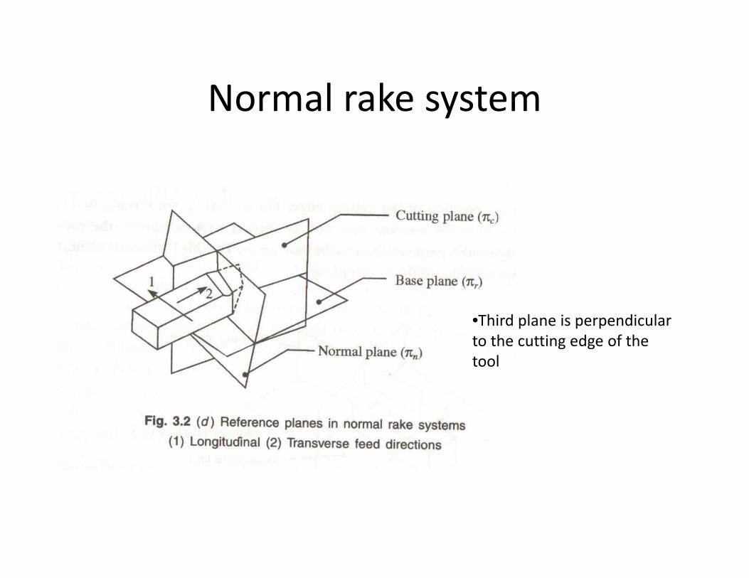
Normal rake systemNormal rake system
•Third plane is perpendicularThird plane is perpendicular to the cutting edge of the tool

System of axesSystem of axes
• These are not the cartesianco‐ordinate axes but traces of thereference plane.
• The auxiliary cutting edge and• The auxiliary cutting edge and auxiliary flank angles are also shown

ASA/Co‐ordinate system

Singlegdnt tod specification in Continental system (ORS)

Single‐point tool specification in British system (MRS)

Single‐point tool specification in International system (NRS)

Single‐point tool specification in American continental t (MRS)system (MRS)

Different nomenclature systemsDifferent nomenclature systems

Selection of tool anglesSelection of tool angles• With zero inclination chip flows parallel to the work surface –
chip disposal problemp p p
• With inclination angle – chip flows – Cutting force, power and Ra is good
• Large – small rake angle
• Flank angle
• End Cutting edge angles provided clear the cutting edge• End Cutting‐edge angles – provided clear the cutting edge from the machined surface and reduce tool chatter. Too large an angle, weak tool and affect heat conduction.
• Side cutting edge affects tool life


Geometry of helical milling cutter

Geometry of twist drill

Features of Orthogonal Chip FormationFeatures of Orthogonal Chip Formation
12:

=
= r (4.1)
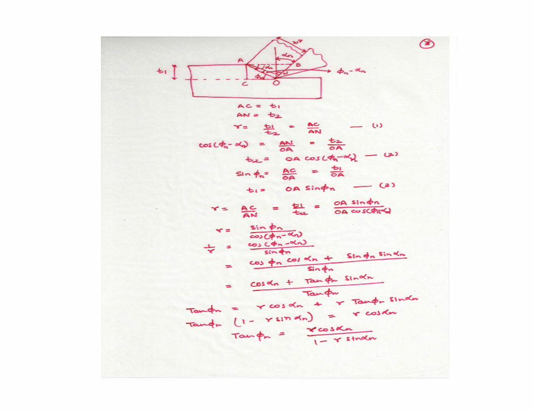
r = Cutting Ratio
(4.2)

(4.3)
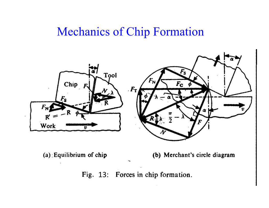
Mechanics of Chip Formation
13:

Express Fc in Fs and FnFt in Fn and FsF in Fc and FtN in Fc and FtFs in Fc and FtFs in Fc and FtFn in Fc and FtR in F and anglesFc in R and friction and rake anglesFt i R d f i ti d k lFt in R and friction and rake angles

(4.4)
(4 5)(4.5)
(4.6a)
(4.6b)
(4.7a)
(4.7b)
(4.8a)
(4.8b)
( )(4.9)
(4.10a)( )
(4.10b)

(4.11)
(4.12)
(4.13)
(4.14)


will be minimum when the denominator is maximum. Differentiating thedenominator with respect to and equating it to zerodenominator with respect to and equating it to zero.
= 0
(4.15)
Using equation (4.15) in equation (4.13), we get
(4 16)(4.16)
can be expressed as In reality shear stress is not completely independent of normal stress
(4.17)
During machining, σ is given by
p
Where σ = normal stress acting on the shear planeshear plane

So, the shear stress can be expressed as
From the circle diagram (Fig. 13 b), we can writeFrom the circle diagram (Fig. 13 b), we can write
Using this in the expression for and writing in terms of , we get

Using equation (4.9) and (4.10 a) along with the foregoing equation, we obtain
(4.18)
Now, applying the principle of minimum energy consumption, we finally get
(4.19)
Where and is constant for the work material. is sometimescalled the machining constant.
It is clear α increases φ increases and μ increases φ decreasesAs the cutting speed increases, μ decerases and so Fc too

Effect of Cutting Parameters on Chip Formation
15:

During an orthogonal machining operation on mild steel, the results obtained areuncut thickness = 0.25 mm, chip thickness = 0.75 mm, w = 2.5 mm, rake angle is zero and C i f 950 N d h f 475 NCutting force = 950 N and thrust force = 475 N.
Determine the co‐efficient of frictionDetermine the ultimate shear stress of the work material

Determination of co‐efficient of friction
•The distribution of shear and normal•The distribution of shear and normal stress on the rake face is not uniform.
• Tip to C, normal stress is high so sticking friction is high• C to D, curling – sliding friction• When normal force is small, F is proportional to normal load. Independent of apparent area Elastic –Independent of apparent area. Elastic plastic region.• When normal force is high, plastic deformation at sliding interface so f i i f i i d d f lfriction force is independent of normal load

Strain rate calculation :
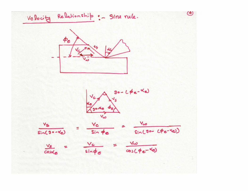
•Strain rate = ((delta S)/(delta y))*(1/(delta t))• Strain rate can be expressed in shear velocity• Strain rate can be expressed in shear velocity•Need for velocity diagram

Measurement of Shear angle
• Direct Method• Indirect Method
Step 1 : determine r ; ltb = (ltb) of chip we calculate tcStep 2 : AB = t/sin (φ) = tc/cos (φ‐α) we get φStep 2 : AB = t/sin (φ) = tc/cos (φ‐α) we get φ
Alternative methodWeight of the chip = ρlctcbc = ρltb
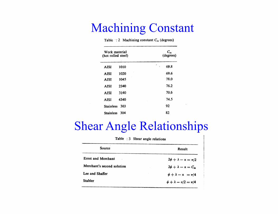
Machining Constant: 2: 2
Shear Angle Relationships: 3

(4.20)Power Consumption
(4.21 a)Specific Energy
(4.21 b): 4
(4.22)
= Uncut thickness, mmQ = Volume rate of material
removalremoval

Mechanics of oblique cutting
When cutting edge inclined by I, then following rake angle comes into existence
1. Normal rake angle2. Velocity rake angle3. Effective rake angle
Because of this two shear angle1. Normal shear angle – angle from shear plane to plane containing the newly formed work
surface measured in a plane normal to cutting edge2 Eff ti h l l i d i th l t i i th tti l it d2. Effective shear angle – angle is measured in the plane containing the cutting velocity and
chip velocity vector

Relationship between different rake angles and inclination


Heat Generation and Cutting Tool Temperature
16: 16
Total rate of heat generation (4 23)Total rate of heat generation
= Rate of heat generation in primary zone
(4.23)
= Rate of heat generation in secondary zone

(4.24)
From relations (4.24) and (4.25),
(4.25)
When a material particle moves across the primary deformation zone, the temperature rise is given byrise is given by
(4.26)
Where= Fraction of primary heat which goes to the workpiece
= Density of the material= Density of the material
= Specific heat of the material
= Uncut thickness width of cut respectively Uncut thickness, width of cut respectively

It has been found that is a function of the shear angle and a nondimensional quantity
(4.27)
= Thermal conductivity of the material= Thermal conductivity of the material
For a wide range of work materials and machining conditions
(4.28)
The maximum temperature rise when the material particle passes through thesecondary deformation zone along the rake face of the tool can be approximatelysecondary deformation zone along the rake face of the tool can be approximatelyexpressed as
(4.29a)
Where is the length of contact between the tool and the chipThe corresponding average temperature rise
(4.29b)
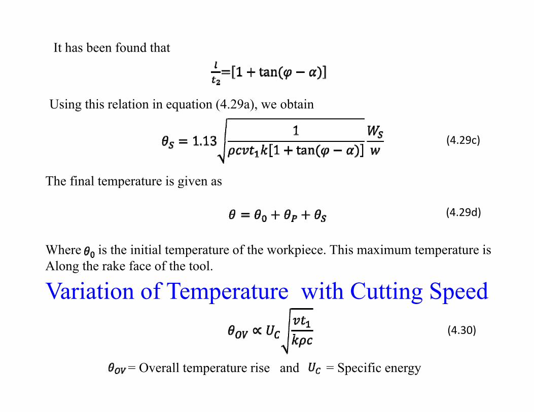
It has been found that
Using this relation in equation (4.29a), we obtain
(4.29c)
The final temperature is given asThe final temperature is given as
(4.29d)
Where is the initial temperature of the workpiece. This maximum temperature isAlong the rake face of the tool.
V i i f T i h C i S dVariation of Temperature with Cutting Speed(4.30)
= Overall temperature rise and = Specific energy

Cutting Parameters: Workpiece Material – SAE B 1113 SteelTool – K2S WCRake Angle - 200
Uncut thickness – 0.06 mm
The overall interface temperature rise is Proportional to the square root of the Cutting speed
: 17

Failure of Cutting Tool and Tool Wear
• Plastic deformation of the tool due to high temperature and large stress• Mechanical breakage of the tool due to large force and insufficient strength
and toughnessand toughness• Blunting of the cutting edge of the tool through a process of gradual wear
: 18
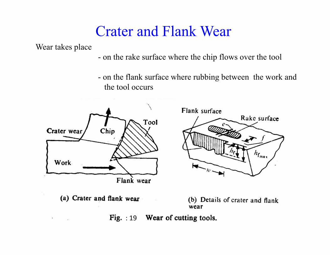
Crater and Flank WearWear takes placeWear takes place
- on the rake surface where the chip flows over the tool
- on the flank surface where rubbing between the work andon the flank surface where rubbing between the work andthe tool occurs
: 19

Tool Wear various mechanism
Adhesion Wear : Surface mating ‐ welding of tool and workpiece materialSmall wear particles – attritious wearLarge wear particles – galling
Abrasion wear : surface asperities plough a series of groovesBasic condition – particles must be harder than the surface.This wear rate through this is process depends on hardness, elastic propertiesAnd the geometry of the mating surfaces.
Diffusion : Two surfaces in close contact, atom from one transfer to other by diffusionDiffusion : Two surfaces in close contact, atom from one transfer to other by diffusionChanges the physical properties like hardness, toughness, etc.Diffusion rate is temperature dependent so depends on sliding rateAmount of material transfer is time of contact and inverse of sliding speed

Growth of Tool WearFlank Wear – Abrasion and adhesionCrater Wear - Diffusion
Break in wear – sharp cutting edge is quickly broken, wear rate high, contact starts from zero and normal pressure is high to cause sub‐surface plastic flow.
: 20

Cutting Tool MaterialsCondition of Hardness Ratio (Proposed by T.N. Loladze)Co d o o a d ess a o ( oposed by .N. o ad e)
(4.31)
: 5

Variables affecting tool life• Cutting conditions• tool geometry• tool material • work material • cutting fluid• cutting fluid
Properties of tool materialProperties of tool material1. Hot hardness2. Toughness3. Thermal conductivity and specific heat should be high4. Co‐efficient of friction between the workpiece and tool
Tool list1. Carbon tool steel2. High Speed steel3. Cemented carbide – WC‐Co with other ingradients like TaC, TiC, etc4. Ceramic oxide5 Ceramic Non oxide5. Ceramic Non oxide6. Coatings – Single and multi layer7. Diamond
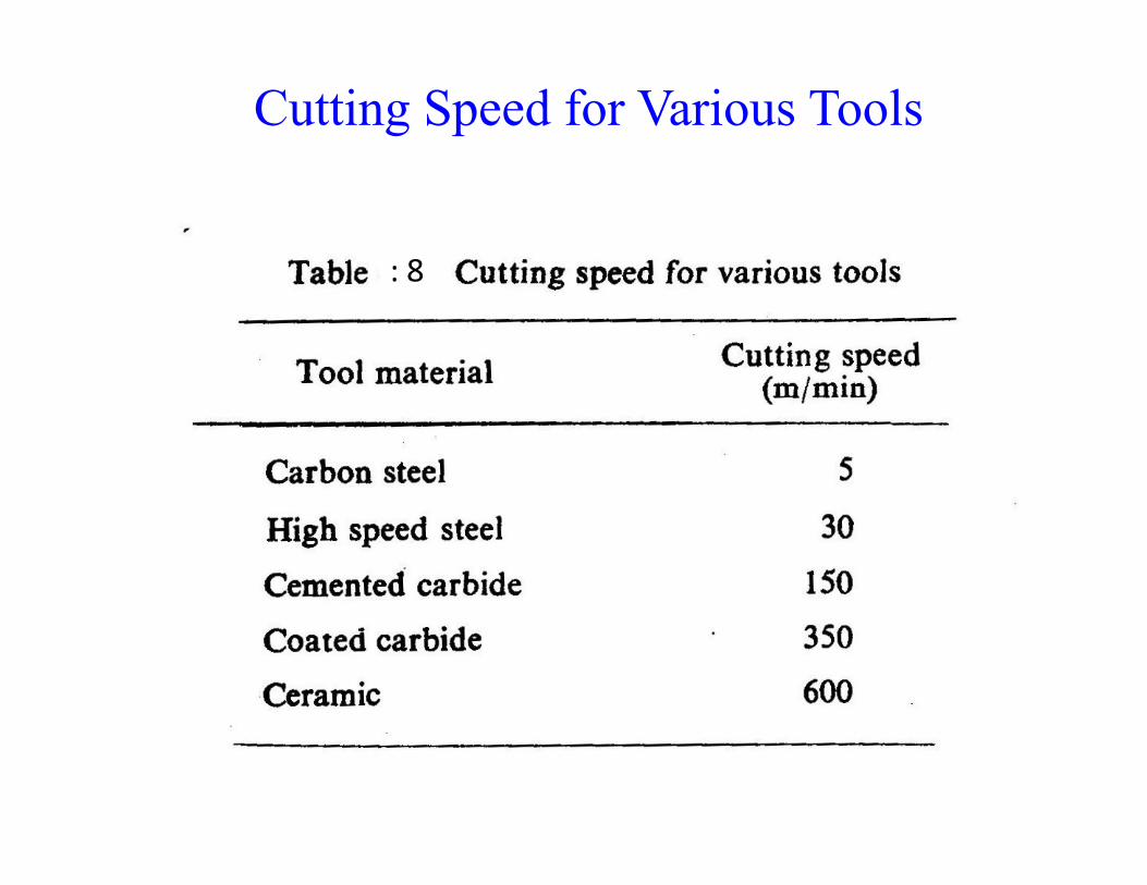
Cutting Speed for Various Tools
: 8: 8

Tool life and machinabilityTool life and machinability
Machinability – ease for machiningMajor for criteria • Machining forces and power consumptionS f fi i h• Surface finish
• Tool Life – flank wear 0.3 mm or flank wear max 0.6 mm
• Velocity has a direct influence on flank wear• VTn= C
C d d l / l d i• n,C= depends on tool, w/p, tool geometry and cutting condition
• T = C’/(V1/nf1/md1/o )/( )

Dependence of Tool Life on Tool Geometry
: 24

Cutting fluids
Ways in which cutting fluid affects machiningC li d f hi t l k b• Cooling down of chip-tool-work zone be
carrying away generated heat•Reducing the coefficient of friction a chip-tool interface•Reducing thermal distortion caused by temperature gradient •Washing of chip•Protecting from corrosion•Protecting from corrosion

Ideal cutting fluidIdeal cutting fluid
• Large specific heat and thermal conductivityLarge specific heat and thermal conductivity• Low viscosity and small molecular size• Suitable reactive constituent• Suitable reactive constituent• Nonpoisonous I i• Inexpensive
Types of cutting fluids• Water based• Mineral oil
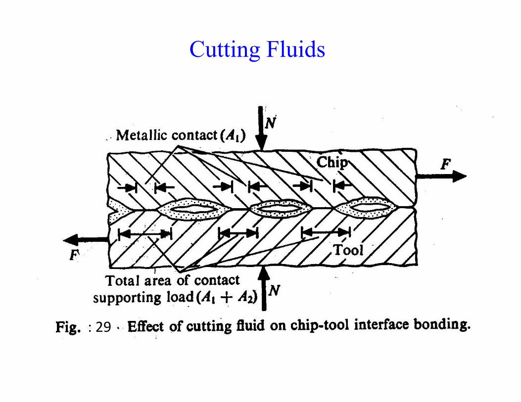
Cutting Fluids
: 29: 29

Change in per cent Heat Distribution with Speed
Fig.: 30 Role of Cutting Speed
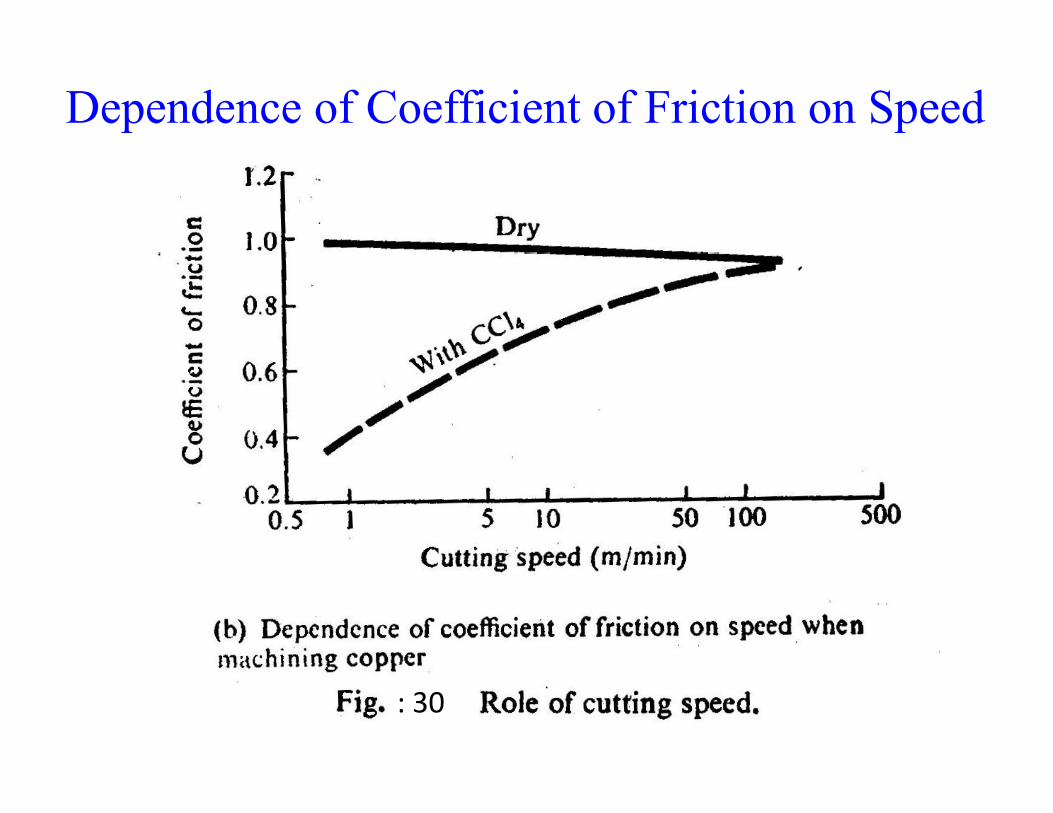
Dependence of Coefficient of Friction on Speed
: 30

Effect of Cutting Environment
: 31: 31