manufacturing process mait - mait4us -...
TRANSCRIPT

Manufacturing Process MAIT
ByByByBy---- RAMAKANT RANARAMAKANT RANARAMAKANT RANARAMAKANT RANA
Metal Casting
Introduction: The metal casting industry plays a key role in all the major sectors of our economy. There are castings in
cars trucks, aircraft, factories, schools, and homes some metal cast parts.
Metal Casting is one of the oldest materials shaping methods known. Casting means pouring molten
metal into a mold with a cavity of the shape to be made, and allowing it to solidify. When solidified, the
desired metal object is taken out from the mold by either breaking the mold or taking the mold apart.
The solidified object is called the casting.
The mold, into which the metal is poured, is made of some heat resisting material. Sand is most often
used as it resists the high temperature of the molten metal.
Permanent molds of metal can also be used to cast products.
Figure: Metal Cast parts
Advantages:
1. Molten material can flow into very small sections so that intricate shapes can be made by this
process.
2. It is possible to cast practically any material that is ferrous or non-ferrous.
3. As the metal can be placed exactly where it is required, large saving in weight can be achieved.
4. The necessary tools required for casting molds are very simple and inexpensive. As a result, for
production of a small lot, it is the ideal process.
5. There are certain parts made from metals and alloys that can only be processed this way.
6. Size and weight of the product is not a limitation for the casting process.
Limitations:
1. Dimensional accuracy and surface finish of the castings made by sand casting processes are a
limitation to this technique.
2. The metal casting process is a labor intensive process.
Manufacturing Process MAIT
ByByByBy---- RAMAKANT RANARAMAKANT RANARAMAKANT RANARAMAKANT RANA
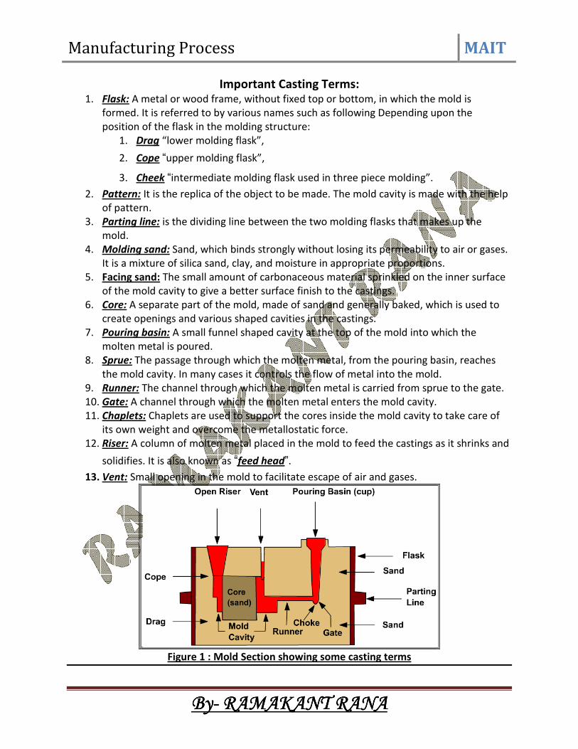
Important Casting Terms:
1. Flask: A metal or wood frame, without fixed top or bottom, in which the mold is
formed. It is referred to by various names such as following Depending upon the
position of the flask in the molding structure:
1. Drag “lower molding flask”,
2. Cope “upper molding flask”,
3. Cheek “intermediate molding flask used in three piece molding”.
2. Pattern: It is the replica of the object to be made. The mold cavity is made with the help
of pattern.
3. Parting line: is the dividing line between the two molding flasks that makes up the
mold.
4. Molding sand: Sand, which binds strongly without losing its permeability to air or gases.
It is a mixture of silica sand, clay, and moisture in appropriate proportions.
5. Facing sand: The small amount of carbonaceous material sprinkled on the inner surface
of the mold cavity to give a better surface finish to the castings.
6. Core: A separate part of the mold, made of sand and generally baked, which is used to
create openings and various shaped cavities in the castings.
7. Pouring basin: A small funnel shaped cavity at the top of the mold into which the
molten metal is poured.
8. Sprue: The passage through which the molten metal, from the pouring basin, reaches
the mold cavity. In many cases it controls the flow of metal into the mold.
9. Runner: The channel through which the molten metal is carried from sprue to the gate.
10. Gate: A channel through which the molten metal enters the mold cavity.
11. Chaplets: Chaplets are used to support the cores inside the mold cavity to take care of
its own weight and overcome the metallostatic force.
12. Riser: A column of molten metal placed in the mold to feed the castings as it shrinks and
solidifies. It is also known as “feed head”. 13. Vent: Small opening in the mold to facilitate escape of air and gases.
Figure 1 : Mold Section showing some casting terms
Manufacturing Process MAIT
ByByByBy---- RAMAKANT RANARAMAKANT RANARAMAKANT RANARAMAKANT RANA
Steps in Making Sand Castings:
1. Patternmaking
2. Core making
3. Molding
4. Melting and pouring
5. Cleaning
Pattern making:
The pattern is a physical model of the casting used to make the mold. The mold is made by
packing some readily formed aggregate material, such as molding sand, around the pattern.
When the pattern is withdrawn, its imprint provides the mold cavity, which is ultimately filled
with metal to become the casting. If the casting is to be hollow, as in the case of pipe fittings,
additional patterns, referred to as cores, are used to form these cavities.
Core making:
Cores are forms, usually made of sand, which are placed into a mold cavity to form the interior
surfaces of castings. Thus the void space between the core and mold-cavity surface is what
eventually becomes the casting.
Molding:
Molding consists of all operations necessary to prepare a mold for receiving molten metal.
Molding usually involves placing a molding aggregate around a pattern held with a supporting
frame, withdrawing the pattern to leave the mold cavity, setting the cores in the mold cavity
and finishing and closing the mold.
Melting and Pouring:
The preparation of molten metal for casting is referred to simply as melting. Melting is usually
done in a specifically designated area of the foundry, and the molten metal is transferred to the
pouring area where the molds are filled.
Cleaning: Cleaning refers to all operations necessary to the removal of sand, scale, and excess
metal from the casting. Burned-on sand and scale are removed to improved the surface
appearance of the casting. Excess metal, in the form of fins, wires, parting line fins, and gates, is
removed. Inspection of the casting for defects and general quality is performed.
Pattern: (see figure 2)
The pattern is the principal tool during the casting process. It is the replica of the object to be
made by the casting process, with some modifications. The main modifications are the addition
of pattern allowances, and the provision of core prints. If the casting is to be hollow, additional
patterns called cores are used to create these cavities in the finished product.
The quality of the casting produced depends upon the material of the pattern, its design, and
construction.
Functions of the Pattern
1. A pattern prepares a mold cavity for the purpose of making a casting.
2. A pattern may contain projections known as core prints if the casting requires a core
and need to be made hollow.

Manufacturing Process MAIT
ByByByBy---- RAMAKANT RANARAMAKANT RANARAMAKANT RANARAMAKANT RANA
3. Runner, gates, and risers used for feeding molten metal in the mold cavity may form a
part of the pattern.
4. Patterns properly made and having finished and smooth surfaces reduce casting
defects.
5. A properly constructed pattern minimizes the overall cost of the castings.
Pattern Material:
Patterns may be constructed from the following materials. Each material has its own
advantages, limitations, and field of application. Some materials used for making patterns are:
wood, metals and alloys, plastic, plaster of Paris, plastic and rubbers, wax, and resins. To be
suitable for use, the pattern material should be:
1. Easily worked, shaped and joined
2. Light in weight
3. Strong, hard and durable
4. Resistant to wear and abrasion
5. Resistant to corrosion, and to chemical reactions
6. Dimensionally stable and unaffected by variations in temperature and humidity
7. Available at low cost
The usual pattern materials are wood, metal, and plastics.
The most commonly used pattern material is wood, since it is readily available and of low
weight. Also, it can be easily shaped and is relatively cheap.
The main disadvantage of wood is its absorption of moisture, which can cause distortion and
dimensional changes. Hence, proper seasoning and upkeep of wood is almost a pre-requisite
for large-scale use of wood as a pattern material.
Figure 2: A typical pattern attached with gating and risering system

Manufacturing Process MAIT
ByByByBy---- RAMAKANT RANARAMAKANT RANARAMAKANT RANARAMAKANT RANA
Pattern Allowances: Pattern allowance is a vital feature as it affects the dimensional characteristics of the casting.
Thus, when the pattern is produced, certain allowances must be given on the sizes specified in
the finished component drawing so that a casting with the particular specification can be made.
The selection of correct allowances greatly helps to reduce machining costs and avoid
rejections.
The allowances usually considered on patterns and core boxes are as follows:
1. Shrinkage or contraction allowance
2. Draft or taper allowance
3. Machining or finish allowance
4. Distortion or camber allowance
5. Rapping allowance
Shrinkage or Contraction Allowance:
All most all cast metals shrink or contract volumetrically on cooling. The metal shrinkage is of
two types:
i. Liquid Shrinkage: it refers to the reduction in volume when the metal changes from
liquid state to solid state at the solidus temperature. To account for this
shrinkage; riser, which feed the liquid metal to the casting, are provided in the mold.
ii. Solid Shrinkage: it refers to the reduction in volume caused when metal loses
temperature in solid state. To account for this, shrinkage allowance is provided on the
patterns.
The rate of contraction with temperature is dependent on the material.
To compensate the solid shrinkage, a shrink rule must be used in laying out the measurements
for the pattern.
The various rate of contraction of various materials are given in following figure.
Table 1: Rate of Contraction of Various Metals
Material Dimension Shrinkage allowance
(inch/ft)
Grey Cast Iron Up to 2 feet
2 feet to 4 feet
over 4 feet
0.125
0.105
0.083
Cast Steel Up to 2 feet
2 feet to 6 feet
over 6 feet
0.251
0.191
0.155
Aluminum Up to 4 feet
4 feet to 6 feet
over 6 feet
0.155
0.143
0.125
Magnesium Up to 4 feet
Over 4 feet
0.173
0.155
Manufacturing Process MAIT
ByByByBy---- RAMAKANT RANARAMAKANT RANARAMAKANT RANARAMAKANT RANA
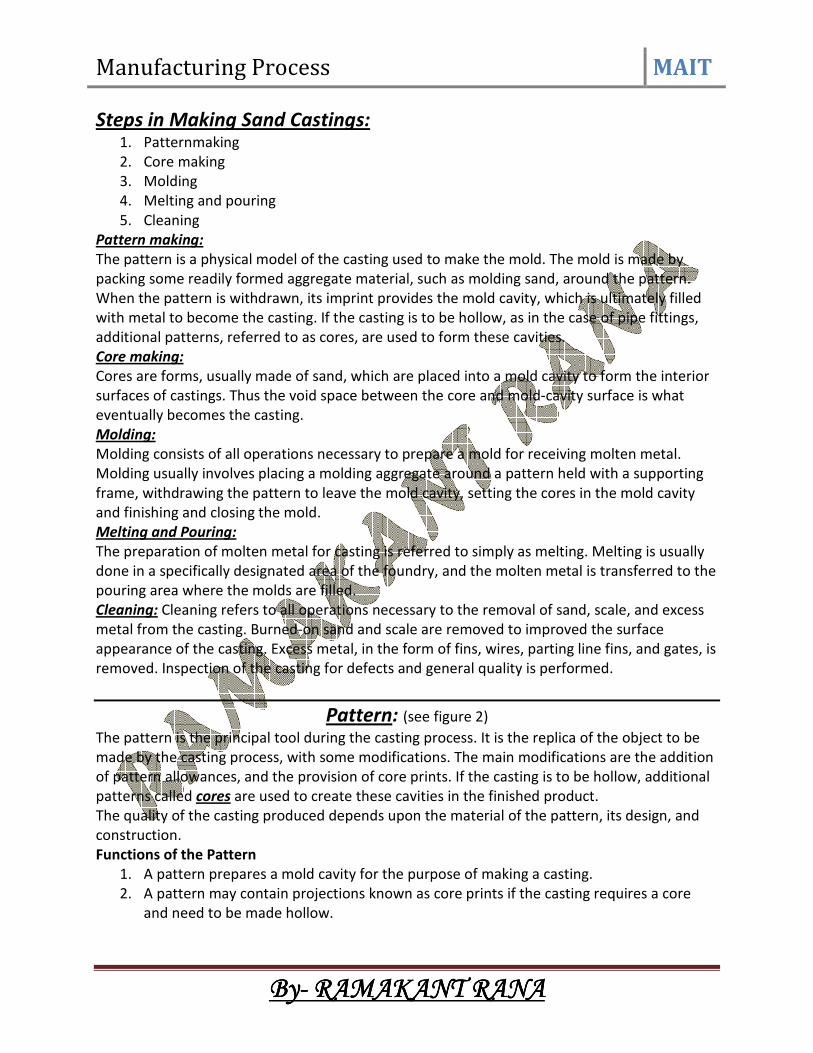
Draft or Taper Allowance: (see animation no.2)
Draft means the taper provided by the pattern maker on all vertical surfaces of the pattern so
that it can be removed from the sand without tearing away the sides of the sand mold and
without excessive rapping by the molder.
Animation no.2 or figure no. 3 (a) shows a pattern having no draft allowance being removed
from the pattern. In this case, till the pattern is completely lifted out, its sides will remain in
contact with the walls of the mold, thus tending to break it.
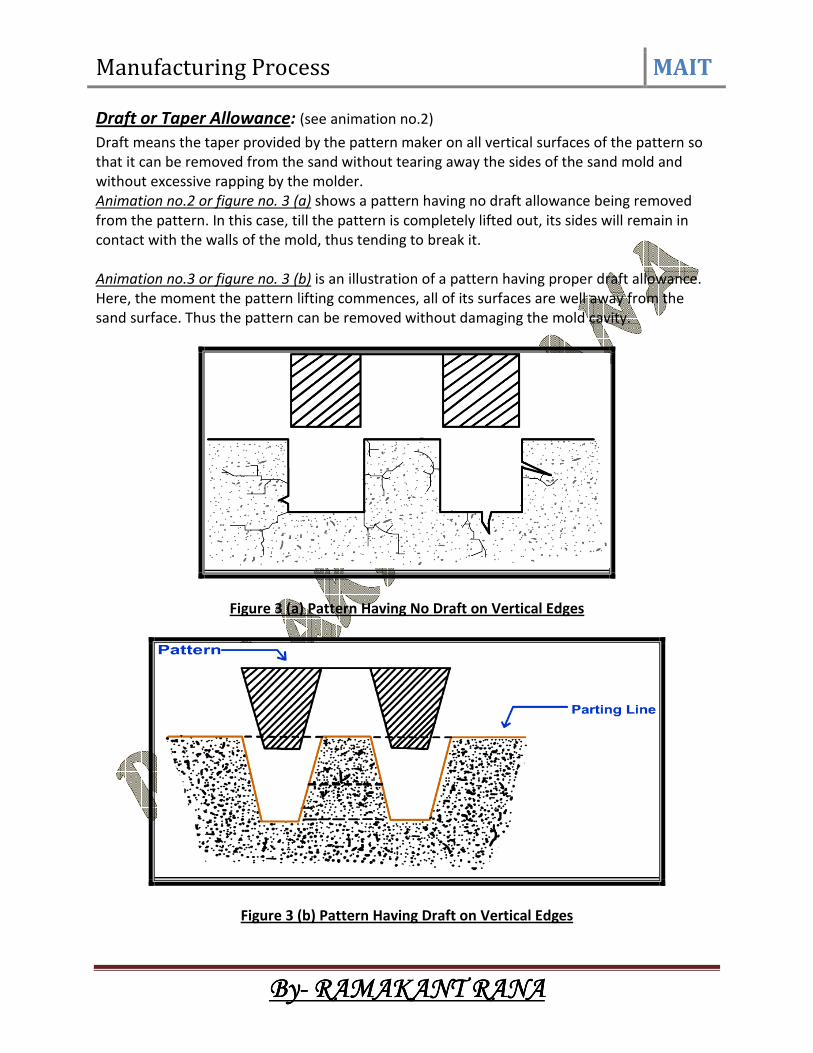
Animation no.3 or figure no. 3 (b) is an illustration of a pattern having proper draft allowance.
Here, the moment the pattern lifting commences, all of its surfaces are well away from the
sand surface. Thus the pattern can be removed without damaging the mold cavity.
Figure 3 (a) Pattern Having No Draft on Vertical Edges
Figure 3 (b) Pattern Having Draft on Vertical Edges

Manufacturing Process MAIT
ByByByBy---- RAMAKANT RANARAMAKANT RANARAMAKANT RANARAMAKANT RANA
Draft allowance varies with the complexity of the sand job.
In general, inner details of the pattern require higher draft than outer surfaces.
The amount of draft depends upon the length of the vertical side of the pattern to be extracted;
the intricacy of the pattern; the method of molding; and pattern material.
Table 2 : Draft Allowances of Various Metals
Pattern material Height of the given
surface (inch)
Draft angle
(External surface)
Draft angle
(Internal surface)
Wood 1
1 to 2
2 to 4
4 to 8
8 to 32
3.00
1.50
1.00
0.75
0.50
3.00
2.50
1.50
1.00
1.00
Metal and plastic 1
1 to 2
2 to 4
4 to 8
8 to 32
1.50
1.00
0.75
0.50
0.50
3.00
2.00
1.00
1.00
0.75
Machining or Finish Allowance:
The finish and accuracy achieved in sand casting are generally poor and therefore when the
casting is functionally required to be of good surface finish or dimensionally accurate, it is
generally achieved by subsequent machining.
Machining or finish allowances are therefore added in the pattern dimension.
The amount of machining allowance to be provided for is affected by the method of molding
and casting used viz. hand molding or machine molding, sand casting or metal mold casting.
The amount of machining allowance is also affected by the size and shape of the casting; the
casting orientation; the metal; and the degree of accuracy and finish required.
The machining allowances recommended for different metal is given in following table no3.
Table 3: Machining Allowances of Various Metals
Metal Dimension (inch) Allowance (inch)
Cast iron Up to 12
12 to 20
20 to 40
0.12
0.20
0.25
Cast steel Up to 6
6 to 20
20 to 40
0.12
0.25
0.30
Non ferrous Up to 8
8 to 12
12 to 40
0.09
0.12
0.16

Manufacturing Process MAIT
ByByByBy---- RAMAKANT RANARAMAKANT RANARAMAKANT RANARAMAKANT RANA
Distortion or Camber Allowance:
Sometimes castings get distorted, during solidification, due to their typical shape. For example,
if the casting has the form of the letter U, V, T, or L etc.
It will tend to contract at the closed end causing the vertical legs to look slightly inclined. This
can be prevented by making the legs of the U, V, T, or L shaped pattern converge slightly
(inward) so that the casting after distortion will have its sides vertical.
The distortion in casting may occur due to internal stresses. These internal stresses are caused
on account of unequal cooling of different section of the casting and hindered contraction.
Measure taken to prevent the distortion in casting include:
i. Modification of casting design
ii. Providing sufficient machining allowance to cover the distortion affect
iii. Providing suitable allowance on the pattern, called camber or distortion allowance
(inverse reflection)
Figure 4: Distortions in Casting
Rapping Allowance:
Before the withdrawal from the sand mold, the pattern is rapped all around the vertical faces to
enlarge the mold cavity slightly, which facilitate its removal. Since it enlarges the final casting
made, it is desirable that the original pattern dimension should be reduced to account for this
increase.
There is no sure way of quantifying this allowance, since it is highly dependent on the foundry
personnel practice involved.
It is a negative allowance and is to be applied only to those dimensions that are parallel to the
parting plane.
Core and Core Prints:
Castings are often required to have holes, recesses, etc. of various sizes and shapes.

Manufacturing Process MAIT
ByByByBy---- RAMAKANT RANARAMAKANT RANARAMAKANT RANARAMAKANT RANA
These impressions can be obtained by using cores. So where coring is required, provision
should be made to support the core inside the mold cavity. Core prints are used to serve this
purpose.
The core print is an added projection on the pattern and it forms a seat in the mold on which
the sand core rests during pouring of the mold. The core print must be of adequate size and
shape so that it can support the weight of the core during the casting operation.
Depending upon the requirement a core can be placed horizontal, vertical and can be hanged
inside the mold cavity. A typical job, its pattern and the mold cavity with core and core print is
shown in following figure no 5.
Figure 5: A Typical Job, its Pattern, and the Mold Cavity

Manufacturing Process MAIT
ByByByBy---- RAMAKANT RANARAMAKANT RANARAMAKANT RANARAMAKANT RANA
Types of Pattern:
Patterns are of various types, each satisfying certain casting requirements.
1. Single piece pattern
2. Split or two piece pattern
3. Match plate pattern
Single Piece Pattern:
The one piece or single pattern is the most inexpensive of all types of patterns.
This type of pattern is used only in cases where the job is very simple and does not create any
withdrawal problems. It is also used for application in very small-scale production or in
prototype development.
This type of pattern is expected to be entirely in the drag and one of the surface is expected to
be flat which is used as the parting plane.
A gating system is made in the mold by cutting sand with the help of sand tools. If no such flat
surface exists, the molding becomes complicated.
A typical one-piece pattern is shown in following figure 6.
Figure 6: A Typical One Piece Pattern
Split or Two Piece Pattern:
It is most widely used type of pattern for intricate castings.
It is split along the parting surface, the position of which is determined by the shape of the
casting.
One half of the pattern is molded in drag and the other half in cope.
The two halves of the pattern must be aligned properly by making use of the dowel pins, which
are fitted, to the cope half of the pattern.
These dowel pins match with the precisely made holes in the drag half of the pattern. A typical
split pattern of a cast iron wheel is shown in following figure.

Manufacturing Process MAIT
ByByByBy---- RAMAKANT RANARAMAKANT RANARAMAKANT RANARAMAKANT RANA
Figure 7 (a): The Details of a Cast Iron Wheel
Figure 7 (b): The Split Piece or Two Piece Pattern of a Cast Iron Wheel

Manufacturing Process MAIT
ByByByBy---- RAMAKANT RANARAMAKANT RANARAMAKANT RANARAMAKANT RANA
Classification of casting Processes: Casting processes can be classified into following FOUR categories:
1. Conventional Molding Processes
a. Green Sand Molding
b. Dry Sand Molding
c. Flask less Molding
2. Chemical Sand Molding Processes
a. Shell Molding
b. Sodium Silicate Molding
c. No-Bake Molding
3. Permanent Mold Processes
a. Gravity Die casting
b. Low and High Pressure Die Casting
4. Special Casting Processes
a. Lost Wax
b. Ceramics Shell Molding
c. Evaporative Pattern Casting
d. Vacuum Sealed Molding
e. Centrifugal Casting
Green Sand Molding:
Green sand is the most diversified molding method used in metal casting operations.
The process utilizes a mold made of compressed or compacted moist sand.
The term "green" denotes the presence of moisture in the molding sand.
The mold material consists of silica sand mixed with a suitable bonding agent (usually clay) and
moisture.
Advantages:
1. Most metals can be cast by this method.
2. Pattern costs and material costs are relatively low.
3. No Limitation with respect to size of casting and type of metal or alloy used
Disadvantages:
1. Surface Finish of the castings obtained by this process is not good and
2. Machining is often required to achieve the finished product.
Sand Mold Making Procedure:
The procedure for making mold of a cast iron wheel is:
• The first step in making mold is to place the pattern on the molding board.
• The drag is placed on the board.
• Dry facing sand is sprinkled over the board and pattern to provide a non sticky layer.
• Molding sand is then riddled in to cover the pattern with the fingers; then the drag is
completely filled.
• The sand is then firmly packed in the drag by means of hand rammers. The ramming
must be proper i.e. it must neither be too hard or soft.

Manufacturing Process MAIT
ByByByBy---- RAMAKANT RANARAMAKANT RANARAMAKANT RANARAMAKANT RANA
• After the ramming is over, the excess sand is leveled off with a straight bar known as a
strike rod.
• With the help of vent rod, vent holes are made in the drag to the full depth of the flask
as well as to the pattern to facilitate the removal of gases during pouring and
solidification.
• The finished drag flask is now rolled over to the bottom board exposing the pattern.
• Cope half of the pattern is then placed over the drag pattern with the help of locating
pins. The cope flask on the drag is located aligning again with the help of pins.
• The dry parting sand is sprinkled all over the drag and on the pattern.
• A sprue pin for making the sprue passage is located at a small distance from the pattern.
In addition, riser pin, if required is placed at an appropriate place.
• The operation of filling, ramming and venting of the cope proceed in the same manner
as performed in the drag.
• The sprue and riser pins are removed first and a pouring basin is scooped out at the top
to pour the liquid metal.
• Then pattern from the cope and drag is removed and facing sand in the form of paste is
applied all over the mold cavity and runners which would give the finished casting a
good surface finish.
• The mold is now assembled. The mold now is ready for pouring (see following figures
and animation no 4.
Figure 8 (a)
Figure 8 (b)

Manufacturing Process MAIT
ByByByBy---- RAMAKANT RANARAMAKANT RANARAMAKANT RANARAMAKANT RANA
Figure (c)
Figure (a, b, c): Sand Mold Making Procedure
Molding Material and Properties: A large variety of molding materials is used in foundries for manufacturing molds and cores.
They include molding sand, system sand or backing sand, facing sand, parting sand, and core
sand.
The choice of molding materials is based on their processing properties. The properties that are
generally required in molding materials are:
Refractoriness:
It is the ability of the molding material to resist the temperature of the liquid metal to be
poured so that it does not get fused with the metal.
The refractoriness of the silica sand is highest.
Permeability:
During pouring and subsequent solidification of a casting, a large amount of gases and steam is
generated. These gases are those that have been absorbed by the metal during melting, air
absorbed from the atmosphere, and the steam generated by the molding and core sand.
If these gases are not allowed to escape from the mold, they would be entrapped inside the
casting and cause casting defects.
To overcome this problem the molding material must be porous.
Green Strength:
The molding sand that contains moisture is termed as green sand.
The green sand particles must have the ability to cling to each other to impart sufficient
strength to the mold.
The green sand must have enough strength so that the constructed mold retains its shape.
Dry Strength:

Manufacturing Process MAIT
ByByByBy---- RAMAKANT RANARAMAKANT RANARAMAKANT RANARAMAKANT RANA
When the molten metal is poured in the mold, the sand around the mold cavity is quickly
converted into dry sand as the moisture in the sand evaporates due to the heat of the molten
metal.
At this stage the molding sand must posses the sufficient strength to retain the exact shape of
the mold cavity and at the same time it must be able to withstand the metallostatic pressure of
the liquid material.
Hot Strength:
As soon as the moisture is eliminated, the sand would reach at a high temperature when the
metal in the mold is still in liquid state.
The strength of the sand that is required to hold the shape of the cavity is called hot strength.
Collapsibility:
The molding sand should also have collapsibility so that during the contraction of the solidified
casting it does not provide any resistance, which may result in cracks in the castings.
Besides these specific properties the molding material should be cheap, reusable and should
have good thermal conductivity.
Molding Sand Composition:
The main ingredients of any molding sand are:
• Base sand,
• Binder, and
• Moisture
Base Sand:
Silica sand is most commonly used base sand.
Other base sands that are also used for making mold are zircon sand, Chromite sand, and
olivine sand.
Silica sand is cheapest among all types of base sand and it is easily available.
Binder:
Binders are of many types such as:
1. Clay binders,
2. Organic binders and
3. Inorganic binders
Clay binders are most commonly used binding agents mixed with the molding sands to provide
the strength.
The most popular clay types are: Kaolinite or fire clay (Al2O3 2 SiO2 2 H2O) and Bentonite
(Al2O3 4 SiO2 nH2O) Of the two the Bentonite can absorb more water which increases its
bonding power.
Moisture:
Clay acquires its bonding action only in the presence of the required amount of moisture.

Manufacturing Process MAIT
ByByByBy---- RAMAKANT RANARAMAKANT RANARAMAKANT RANARAMAKANT RANA
When water is added to clay, it penetrates the mixture and forms a microfilm, which coats the
surface of each flake of the clay.
The amount of water used should be properly controlled.
This is because a part of the water, which coats the surface of the clay flakes, helps in bonding,
while the remainder helps in improving the plasticity.
A typical composition of molding sand is shown following.
Table 4: A Typical Composition of Molding Sand
Molding Sand Constituent Weight Percent
Silica sand 92
Clay (Sodium Bentonite) 8
Water 4
Dry Sand Molding:
When it is desired that the gas forming materials are lowered in the molds, air-dried molds are
sometimes preferred to green sand molds. Two types of drying of molds are often required.
1. Skin drying and
2. Complete mold drying.
In skin drying a firm mold face is produced. Shakeout of the mold is almost as good as that
obtained with green sand molding. The most common method of drying the refractory mold
coating uses hot air, gas or oil flame.
Shell Molding Process:
It is a process in which, the sand mixed with a thermosetting resin is allowed to come in contact
with a heated pattern plate (200oC), this causes a skin (Shell) of about 3.5 mm of sand/plastic
mixture to adhere to the pattern.. Then the shell is removed from the pattern. The cope and
drag shells are kept in a flask with necessary backup material and the molten metal is poured
into the mold.
This process can produce complex parts with good surface finish 1.25 µm to 3.75 µm, and
dimensional tolerance of 0.5 %.

Manufacturing Process MAIT
ByByByBy---- RAMAKANT RANARAMAKANT RANARAMAKANT RANARAMAKANT RANA
A good surface finish and good size tolerance reduce the need for machining.
The process overall is quite cost effective due to reduced machining and cleanup costs.
The materials that can be used with this process are cast irons, and aluminum and copper
alloys.
Permanent Mold Process:
In all the processes, a mold need to be prepared for each of the casting produced.
For large-scale production, making a mold, for every casting to be produced, may be difficult
and expensive.
Therefore, a permanent mold, called the die is made from which a large number of castings can
be produced, the molds are usually made of cast iron or steel, although graphite, copper and
aluminum have also been used as mold materials.
The process in which we use a die to make the castings is called permanent mold casting or
gravity die casting.
Some time in die-casting we inject the molten metal with a high pressure. When we apply
pressure in injecting the metal it is called pressure die casting process.
Advantages:
• Permanent Molding produces a sound dense casting with superior mechanical
properties.
• The castings produced are quite uniform in shape have a higher degree of dimensional
accuracy than castings produced in sand
• The permanent mold process is also capable of producing a consistent quality of finish
on castings
Disadvantages:
• The cost of tooling is usually higher than for sand castings
• The process is generally limited to the production of small castings of simple exterior
design, although complex castings such as aluminum engine blocks and heads are now
commonplace.
Centrifugal Casting:
In this process, the mold is rotated rapidly about its central axis as the metal is poured into it.
Because of the centrifugal force, a continuous pressure will be acting on the metal as it
solidifies.
This process is normally used for the making of hollow pipes, tubes, hollow bushes, etc., which
are axisymmetric with a concentric hole. Since the metal is always pushed outward because of
the centrifugal force, no core needs to be used for making the concentric hole.
The mold can be rotated about a vertical, horizontal or an inclined axis or about its horizontal
and vertical axes simultaneously.

Manufacturing Process MAIT
ByByByBy---- RAMAKANT RANARAMAKANT RANARAMAKANT RANARAMAKANT RANA
The length and outside diameter are fixed by the mold cavity dimensions while the inside
diameter is determined by the amount of molten metal poured into the mold.
Alternatively, see animations no 5 & 6.
Advantages:
• Formation of hollow interiors in cylinders without cores
• Less material required for gate
• Fine grained structure at the outer surface of the casting free of gas and shrinkage
cavities and porosity
Disadvantages:
• More segregation of alloy component during pouring under the forces of rotation
• Contamination of internal surface of castings with non-metallic inclusions
• Inaccurate internal diameter

Manufacturing Process MAIT
ByByByBy---- RAMAKANT RANARAMAKANT RANARAMAKANT RANARAMAKANT RANA
Investment Casting Process: (see following figure or animation no 7)
1) The root of the investment casting process, comes from the “lost wax” method dates
back to at least the fourth millennium B.C.
2) The artists and sculptors of ancient Egypt used the investment casting process to create
intricately detailed jewelry, pectorals and idols.
3) The investment casting process also called lost wax process begins with the production
of wax replicas or patterns of the desired shape of the castings.
4) A pattern is needed for every casting to be produced. The patterns are prepared by
injecting wax or polystyrene in a metal dies.
5) A number of patterns are attached to a central wax sprue to form a assembly.
6) The mold is prepared by surrounding the pattern with refractory slurry that can set at
room temperature.
7) The mold is then heated so that pattern melts and flows out, leaving a clean cavity
behind.
8) The mould is further hardened by heating and the molten metal is poured while it is still
hot.
9) When the casting is solidified, the mold is broken and the casting taken out.
The basic steps of the investment casting process are:
1. Production of heat-disposable wax, plastic, or polystyrene patterns
2. Assembly of these patterns onto a gating system
3. “Investing” or covering the pattern assembly with refractory slurry
4. Melting the pattern assembly to remove the pattern material
Manufacturing Process MAIT
ByByByBy---- RAMAKANT RANARAMAKANT RANARAMAKANT RANARAMAKANT RANA
5. Firing the mold to remove the last traces of the pattern material
6. Pouring
7. Knockout, cutoff and finishing.
Advantages:
• Formation of hollow interiors in cylinders without cores
• Less material required for gate
• Fine grained structure at the outer surface of the casting free of gas and shrinkage
cavities and porosity
Disadvantages:
• More segregation of alloy component during pouring under the forces of rotation
• Contamination of internal surface of castings with non-metallic inclusions
• Inaccurate internal diameter

Manufacturing Process MAIT
ByByByBy---- RAMAKANT RANARAMAKANT RANARAMAKANT RANARAMAKANT RANA
Melting Practices:
Melting is an equally important parameter for obtaining a quality castings. A number of
furnaces can be used for melting the metal, to be used, to make a metal casting.
The choice of furnace depends on the type of metal to be melted.
Some of the furnaces used in metal casting are as following:
• Crucible furnaces
• Cupola
• Induction furnace
• Reverberatory furnace
Crucible Furnace:
Crucible furnaces are small capacity typically used for small melting applications. Crucible
furnace is suitable for the batch type foundries where the metal requirement is intermittent.
The metal is placed in a crucible which is made of clay and graphite. The energy is applied
indirectly to the metal by heating the crucible by coke, oil or gas. The heating of crucible is done
by coke, oil or gas.
Coke-Fired Furnace:
• Primarily used for non-ferrous metals
• Furnace is of a cylindrical shape
• Also known as pit furnace
• Preparation involves: first to make a deep bed of coke in the furnace
• Burn the coke till it attains the state of maximum combustion
• Insert the crucible in the coke bed
• Remove the crucible when the melt reaches to desired temperature
Figure 13: Coke Fired Crucible Furnace

Manufacturing Process MAIT
ByByByBy---- RAMAKANT RANARAMAKANT RANARAMAKANT RANARAMAKANT RANA
Oil-Fired Furnace:
• Primarily used for non-ferrous metals
• Furnace is of a cylindrical shape
• Advantages include: no wastage of fuel
• Less contamination of the metal
• Absorption of water vapor is least as the metal melts inside the closed metallic furnace
Cupola:
Cupola furnaces are tall, cylindrical furnaces used to melt iron and ferrous alloys in foundry
operations.
Alternating layers of metal and ferrous alloys, coke, and limestone are fed into the furnace from
the top.
A schematic diagram of a cupola is shown in following figure.
This diagram of a cupola illustrates the furnace's cylindrical shaft lined with refractory and the
alternating layers of coke and metal scrap.
The molten metal flows out of a spout at the bottom of the cupola.
Figure: Schematic of a Cupola
Description of Cupola:
• The cupola consists of a vertical cylindrical steel sheet and lined inside with acid
refractory bricks. The lining is generally thicker in the lower portion of the cupola as the
temperature are higher than in upper portion.

Manufacturing Process MAIT
ByByByBy---- RAMAKANT RANARAMAKANT RANARAMAKANT RANARAMAKANT RANA
• There is a charging door through which coke, pig iron, steel scrap and flux is charged
• The blast is blown through the tuyeres. These tuyeres are arranged in one or more row
around the periphery of cupola.
• Hot gases which ascends from the bottom (combustion zone) preheats the iron in the
preheating zone
• Cupolas are provided with a drop bottom door through which debris, consisting of coke,
slag etc. can be discharged at the end of the melt
• A slag hole is provided to remove the slag from the melt.
• Through the tap hole molten metal is poured into the ladle.
• At the top conical cap called the spark arrest is provided to prevent the spark emerging
to outside.
Operation of Cupola:
The cupola is charged with wood at the bottom.
On the top of the wood a bed of coke is built.
Alternating layers of metal and ferrous alloys, coke, and limestone are fed into the furnace from
the top.
The purpose of adding flux is to eliminate the impurities and to protect the metal from
oxidation.
Air blast is opened for the complete combustion of coke.
When sufficient metal has been melted that slag hole is first opened to remove the slag.
Tap hole is then opened to collect the metal in the ladle.
Reverberatory furnace:
A furnace or kiln in which the material under treatment is heated indirectly by means of a flame
deflected downward from the roof.
Reverberatory furnaces are used in copper, tin, and nickel production, in the production of
certain concretes and cements, and in aluminum.
Reverberatory furnaces heat the metal to melting temperatures with direct-fired wall-mounted
burners.
The primary mode of heat transfer is through radiation from the refractory brick walls to the
metal, but convective heat transfer also provides additional heating from the burner to the
metal.
The advantages provided by reverberatory melters is the high volume processing rate, and low
operating and maintenance costs.
The disadvantages of the reverberatory melters are :
1) The high metal oxidation rates,
2) Low efficiencies, and
3) Large floor space is required.
A schematic of Reverberatory furnace is shown in following figure.

Manufacturing Process MAIT
ByByByBy---- RAMAKANT RANARAMAKANT RANARAMAKANT RANARAMAKANT RANA
Figure: Schematic of a Reverberatory Furnace
Induction furnace:
Induction heating is a heating method. This method occurs when an electrically conductive
material is placed in a varying magnetic field.
Induction heating is a rapid form of heating in which a current is induced directly into the part
being heated.
Induction heating is a non-contact form of heating.
The heating system in an induction furnace includes:
1. Induction heating power supply,
2. Induction heating coil,
3. Water-cooling source, which cools the coil and several internal components inside the
power supply.
The induction heating power supply sends alternating current through the induction coil, which
generates a magnetic field.
Induction furnaces work on the principle of a transformer.
An alternative electromagnetic field induces eddy currents in the metal which converts the
electric energy to heat without any physical contact between the induction coil and the work
piece.
A schematic diagram of induction furnace is shown in following figure.

Manufacturing Process MAIT
ByByByBy---- RAMAKANT RANARAMAKANT RANARAMAKANT RANARAMAKANT RANA
Figure: Schematic of a Induction Furnace
The furnace contains a crucible surrounded by a water cooled copper coil.
The coil is called primary coil to which a high frequency current is supplied.
By induction secondary currents, called eddy currents are produced in the crucible.
High temperature can be obtained by this method.
Induction furnaces are of two types:
1) Cored furnace and
2) Coreless furnace.
Cored furnaces are used almost exclusively as holding furnaces. In cored furnace the
electromagnetic field heats the metal between two coils.
Coreless furnaces heat the metal via an external primary coil.
Advantages of Induction Furnace:
• Induction heating is a clean form of heating
• High rate of melting or high melting efficiency
• Alloyed steels can be melted without any loss of alloying elements
• Controllable and localized heating
Disadvantages of Induction Furnace:
• High capital cost of the equipment
• High operating cost

Manufacturing Process MAIT
ByByByBy---- RAMAKANT RANARAMAKANT RANARAMAKANT RANARAMAKANT RANA
Gating System: The assembly of channels which facilitates the molten metal to enter into the mold cavity is
called the gating system.
The gating system refers to all passage ways through which molten metal passes to enter into
the mold cavity.
The nomenclature of gating system depends upon the function of different channels which they
perform.
• Down gates or sprue
• Cross gates or runners
• Ingates or gates
The metal flows down from the pouring basin or pouring cup into the down gate or sprue and
passes through the cross gate or channels and ingates or gates before entering into the mold
cavity.
Figure 17: Schematic of Gating System
Goals of Gating System:
The goals for the gating system are
• To minimize turbulence to avoid trapping gasses into the mold
• To get enough metal into the mold cavity before the metal starts to solidify
• To avoid shrinkage
• Establish the best possible temperature gradient in the solidifying casting so that the
shrinkage if occurs must be in the gating system not in the required cast part.
• Incorporates a system for trapping the non-metallic inclusions
Hydraulic Principles used in the Gating System:
Reynolds’s Number:
Nature of flow in the gating system can be established by calculating Reynold's number

Manufacturing Process MAIT
ByByByBy---- RAMAKANT RANARAMAKANT RANARAMAKANT RANARAMAKANT RANA
RN = Reynold's number
V = Mean Velocity of flow
D = Diameter of tubular flow
µ = Kinematics Viscosity = Dynamic viscosity / Density
ρ = Fluid density
When the Reynolds’s number is less than 2000 stream line flow results and when the number is
more than 2000 turbulent flow prevails.
As far as possible the turbulent flow must be avoided in the sand mold as because of the
turbulence sand particles gets dislodged from the mold or the gating system and may enter into
the mould cavity leading to the production of defective casting.
Excess turbulence causes:
• Inclusion of dross or slag
• Air aspiration into the mold
• Erosion of the mold walls
Bernoulli's Equation:
h = height of liquid
P = Static Pressure
V = metal velocity
G = Acceleration due to gravity
ρ = Fluid density
Turbulence can be avoided by incorporating small changes in the design of gating system.
The sharp changes in the flow should be avoided to smooth changes.
The gating system must be designed in such a way that the system always runs full with the
liquid metal.
The most important things to remember in designing runners and gates are to avoid sharp
corners.
Any changes in direction or cross sectional area should make use of rounded corners.
To avoid the aspiration the tapered sprues are designed in the gating systems.
A sprue tapered to a smaller size at its bottom will create a choke which will help keep the
sprue full of molten metal.
Types of Gating Systems:
The gating systems are of two types:
• Pressurized gating system
• Un-pressurized gating system

Manufacturing Process MAIT
ByByByBy---- RAMAKANT RANARAMAKANT RANARAMAKANT RANARAMAKANT RANA
Pressurized Gating System:
• The total cross sectional area decreases towards the mold cavity
• Back pressure is maintained by the restrictions in the metal flow
• Flow of liquid (volume) is almost equal from all gates
• Back pressure helps in reducing the aspiration as the sprue always runs full
• Because of the restrictions the metal flows at high velocity leading to more turbulence
and chances of mold erosion
Un-Pressurized Gating System:
• The total cross sectional area increases towards the mold cavity
• Restriction only at the bottom of sprue
• Flow of liquid (volume) is different from all gates
• aspiration in the gating system as the system never runs full
• Less turbulence
Functions of Risers:
• Provide extra metal to compensate for the volumetric shrinkage
• Allow mold gases to escape
• Provide extra metal pressure on the solidifying mold to reproduce mold details more
exact
Design Requirements of Risers:
1. Riser size: For a sound casting riser must be last to freeze.
The ratio of (volume / surface area)2 of the riser must be greater than that of the
casting.
However, when this condition does not meet the metal in the riser can be kept in liquid
state by heating it externally or using exothermic materials in the risers.
2. Riser placement: the spacing of risers in the casting must be considered by effectively
calculating the feeding distance of the risers.
3. Riser shape: cylindrical risers are recommended for most of the castings as spherical
risers, although considers as best, are difficult to cast.
To increase volume/surface area ratio the bottom of the riser can be shaped as
hemisphere.

Manufacturing Process MAIT
ByByByBy---- RAMAKANT RANARAMAKANT RANARAMAKANT RANARAMAKANT RANA
Casting Defects: The following are the major defects, which are likely to occur in sand castings
• Gas defects
• Shrinkage cavities
• Molding material defects
• Pouring metal defects
• Mold shift
Gas Defects: A condition existing in a casting caused by the trapping of gas in the molten metal or by mold
gases evolved during the pouring of the casting.
The defects in this category can be classified into blowholes and pinhole porosity.
Blowholes are spherical or elongated cavities present in the casting on the surface or inside the
casting.
Pinhole porosity occurs due to the dissolution of hydrogen gas, which gets entrapped during
heating of molten metal.
Causes
The lower gas-passing tendency of the mold, which may be due to lower venting, lower
permeability of the mold or improper design of the casting.
The lower permeability is caused by finer grain size of the sand, high percentage of clay in mold
mixture, and excessive moisture present in the mold.
• Metal contains gas
• Mold is too hot
• Poor mold burnout
Shrinkage Cavities: These are caused by liquid shrinkage occurring during the solidification of the casting.
To compensate for this, proper feeding of liquid metal is required.
For this reason risers are placed at the appropriate places in the mold.
Sprues may be too thin, too long or not attached in the proper location, causing shrinkage
cavities.
It is recommended to use thick sprues to avoid shrinkage cavities.
Molding Material Defects: The defects in this category are cuts and washes, metal penetration, fusion, and swell.
Cut and washes: These appear as rough spots and areas of excess metal, and are caused by erosion of molding
sand by the flowing metal.
This is caused by the molding sand not having enough strength and the molten metal flowing at
high velocity.
Manufacturing Process MAIT
ByByByBy---- RAMAKANT RANARAMAKANT RANARAMAKANT RANARAMAKANT RANA
The former can be taken care of by the proper choice of molding sand and the latter can be
overcome by the proper design of the gating system.
Metal penetration: When molten metal enters into the gaps between sand grains, the result is a rough casting
surface.
This occurs because the sand is coarse or no mold wash was applied on the surface of the mold.
The coarser the sand grains more the metal penetration.
Fusion: This is caused by the fusion of the sand grains with the molten metal, giving a brittle, glassy
appearance on the casting surface.
The main reason for this is that the clay or the sand particles are of lower refractoriness or that
the pouring temperature is too high.
Swell: Under the influence of metallostatic forces, the mold wall may move back causing a swell in the
dimension of the casting.
A proper ramming of the mold will correct this defect.
Inclusions: Particles of slag, refractory materials, sand or deoxidation products are trapped in the casting
during pouring solidification.
The provision of choke in the gating system and the pouring basin at the top of the mold can
prevent this defect.
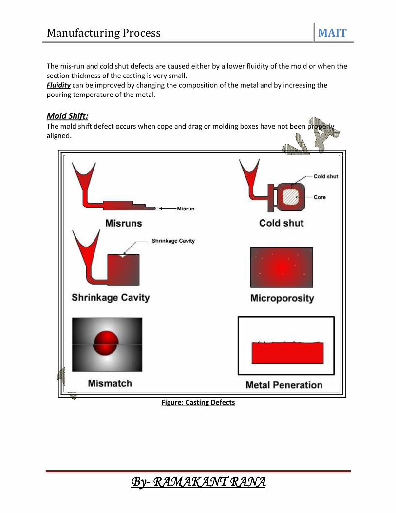
Pouring Metal Defects: The likely defects in this category are
• Mis-runs and
• Cold shuts.
A mis-run is caused when the metal is unable to fill the mold cavity completely and thus leaves
unfilled cavities. A mis-run results when the metal is too cold to flow to the extremities of the
mold cavity before freezing. Long, thin sections are subject to this defect and should be avoided
in casting design.
A cold shut is caused when two streams while meeting in the mold cavity, do not fuse together
properly thus forming a discontinuity in the casting. When the molten metal is poured into the
mold cavity through more-than-one gate, multiple liquid fronts will have to flow together and
become one solid.
If the flowing metal fronts are too cool, they may not flow together, but will leave a seam in the
part. Such a seam is called a cold shut, and can be prevented by assuring sufficient superheat in
the poured metal and thick enough walls in the casting design.
Manufacturing Process MAIT
ByByByBy---- RAMAKANT RANARAMAKANT RANARAMAKANT RANARAMAKANT RANA
The mis-run and cold shut defects are caused either by a lower fluidity of the mold or when the
section thickness of the casting is very small.
Fluidity can be improved by changing the composition of the metal and by increasing the
pouring temperature of the metal.
Mold Shift: The mold shift defect occurs when cope and drag or molding boxes have not been properly
aligned.
Figure: Casting Defects