manual - descargas.futurasmus-knxgroup.org€¦ · language components ... (eibzeitmaster1.code +...
TRANSCRIPT
Arcus-EDS GmbH
Manual
ArcSuite 2.1.2
MicroVis MicroVis II MicroFM
Version: 21.05.2006
Manual Arcsuite_2.1.2
- 2 -
Index
INTRODUCTION ........................................................................................................ 4
Abstracts .............................................................................................................................................................. 4
1. ArcSuite....................................................................................................................................................... 4
1.1. Installation ............................................................................................................................................. 4
1.2. Recommendations for the use of Arcsuite ................................................................................... 5
1.3. Modules .................................................................................................................................................. 6
1.4. System .................................................................................................................................................... 6
1.5. Settings .................................................................................................................................................. 7 1.5.1. Settings............................................................................................................................................................... 7 1.5.2. Changing database .......................................................................................................................................... 7
2. THE MICROFM MODULE................................................................................... 8
2.1. Introduction ........................................................................................................................................... 8
2.2. System Information ............................................................................................................................. 8
2.3. Control element .................................................................................................................................... 8
2.4. DCF-77-Receiver .................................................................................................................................. 9 2.4.1. Frequency Search ............................................................................................................................................ 9 2.4.2. Receiving the Time Signal ............................................................................................................................. 9 2.4.3. Programming..................................................................................................................................................... 9 2.4.4. Code example.................................................................................................................................................. 10
2.5. Program module................................................................................................................................. 12
2.6. Programming ...................................................................................................................................... 12 2.6.1. Projects............................................................................................................................................................. 12 2.6.2. Connection....................................................................................................................................................... 12 2.6.3. EIB Settings ..................................................................................................................................................... 13 2.6.3.1. Import and edit EIB- objects................................................................................................................... 13 2.6.3.2. Manual processing/handling EIB- Objects ......................................................................................... 14 2.6.3.3. Physical Address ...................................................................................................................................... 14 2.6.4. Command Interface........................................................................................................................................ 15 2.6.5. Language Components ................................................................................................................................ 15 2.6.6. Example ............................................................................................................................................................ 28 2.6.7. Preprocessor ................................................................................................................................................... 31
3. MICROVIS MODULE ........................................................................................ 32
3.1. Introduction ......................................................................................................................................... 32
3.2. System Information ........................................................................................................................... 32
3.3. Project Administration...................................................................................................................... 32 3.3.1. New Project...................................................................................................................................................... 32 3.3.2. Open Project.................................................................................................................................................... 33 3.3.3. Delete Project .................................................................................................................................................. 33 3.3.4. Save Project..................................................................................................................................................... 33 3.3.5. Save Project As............................................................................................................................................... 33
Manual Arcsuite_2.1.2
- 3 -
3.3.6. Project Properties .......................................................................................................................................... 33 3.3.7. Export Project ................................................................................................................................................. 33
3.4. Current Project ................................................................................................................................... 34 3.4.1. Preview ............................................................................................................................................................. 34 3.4.2. Project Size ...................................................................................................................................................... 34 3.4.3. Transmission................................................................................................................................................... 34 3.4.4. Physical Address ........................................................................................................................................... 34 3.4.5. Print ................................................................................................................................................................... 35 3.4.6. EIB-Settings ..................................................................................................................................................... 36 3.4.6.1. Import and Editation of EIB- Objects ................................................................................................... 36 3.4.6.2. Manual handling of EIB- Objects........................................................................................................... 37
3.5. Page Architecture and Navigation................................................................................................. 37 3.5.1. Navigation ........................................................................................................................................................ 37 3.5.2. System page .................................................................................................................................................... 38 3.5.3. Alarm Functions ............................................................................................................................................. 39 3.5.4. Focus order...................................................................................................................................................... 39
3.6. Elements for Page Layout ............................................................................................................... 40 3.6.1. Properties of the Elements .......................................................................................................................... 40 3.6.2. Static Elements ............................................................................................................................................... 42
3.6.2.1. Static Rectangle ................................................................................................................................... 42 3.6.2.2. Static Text field..................................................................................................................................... 42 3.6.2.3. Static image........................................................................................................................................... 43 3.6.2.4. Showing System Time ........................................................................................................................ 43 3.6.2.5. Showing System Date......................................................................................................................... 43
3.6.3. System Elements............................................................................................................................................ 44 3.6.3.1. System time........................................................................................................................................... 44 3.6.3.2. System date........................................................................................................................................... 45 3.6.3.3. Standby Timeout:................................................................................................................................. 45 3.6.3.4. Programming the Physical Address ............................................................................................... 45 3.6.3.5. Contrast and Brightness.................................................................................................................... 45
3.6.4. EIB/KNX Elements.......................................................................................................................................... 47 3.6.4.1. Switches and Buttons......................................................................................................................... 48 3.6.4.2. Dimmer ................................................................................................................................................... 48 3.6.4.3. Values ..................................................................................................................................................... 49 3.6.4.4. Lists of Pictures and Values ............................................................................................................. 49 3.6.4.5. Lists of Caption and Values .............................................................................................................. 49 3.6.4.6. Room temperature-thermostat (RTR) ............................................................................................. 50 3.6.4.7. Value Bars ............................................................................................................................................. 51
3.6.5. MicroVis II Functions..................................................................................................................................... 52 3.6.5.1. Selection ................................................................................................................................................ 52 3.6.5.2. User functions ...................................................................................................................................... 52 3.6.5.3. Timer ....................................................................................................................................................... 53 3.6.5.4. Security PIN........................................................................................................................................... 54 3.6.5.5. Scene Management ............................................................................................................................. 54
3.7. Services and Suggestions............................................................................................................... 55
4. PROJECT EXAMPLES..................................................................................... 56 4.1. Example4-mvis................................................................................................................................................ 56 4.2. Example1-mvis2 ............................................................................................................................................. 56 4.3. Example2-mvis2 ............................................................................................................................................. 57
5. PRODUCTS ...................................................................................................... 60 5.1. Funktionsmodul MicroFM-Modul ............................................................................................................. 60 5.2. LCD-Color-Display MicroVis .................................................................................................................... 60 5.3. LCD-Colour - Display MicroVis II............................................................................................................. 62
6. Fitting......................................................................................................................................................... 63
6.1. Fitting FM-Modul ................................................................................................................................ 63 6.1.1. Opening of the FM-Modul............................................................................................................................. 63 6.1.2. Plastic Foil........................................................................................................................................................ 63

Manual Arcsuite_2.1.2
- 4 -
6.2. Fitting MicroVis .................................................................................................................................. 64 6.2.1. Supporting Frame .......................................................................................................................................... 64 6.2.2. USB- und EIB- Connection........................................................................................................................... 64
Introduction
Welcome to Software Suite Help. On these pages you will get instructions on how to carry out your ideas with ARC- Suite step by step. The most important points are illustrated directly with simple examples, so you only have to follow the described actions. If you still have further questions visit our website (www.arcus-eds.de). We regularly offer free updates (documents& programs) to make the work easier for you.
Abstracts
This document contains information such as data, illustrations, values and others that are subject to change without prior notice. Additional information is available under www.arcus-eds.de.
We reserve the right to make technical changes!
All product- descriptions used in this documentation are registered trademarks of the respective companies. No parts of this document may be copied or transmitted without the explicit permission of Arcus-EDS GmbH, irrespective of purpose or way.
All rights reserved! © by Arcus-EDS GmbH
1. ArcSuite
The ArcSuite is a base module for all Java© based Arcus-EDS GmbH modules.
1.1. Installation
- Download the newly packed setup “arcsuite_2_1_2.zip” for our ArcSuite from our homepage www.arcus-eds.de. Open the file “setup.exe.” under “Arcsuite2.1.2” on the CD delivered with your package.
- Unzip the file “arcsuite_2_1_2”.zip - Start the Setup.exe by double-clicking - ArcSuite requires approx. 17 Mb of disc drive capacity - You will be asked to choose a language (English or German) while the file is being unzipped. - Follow the setup-assistant - If the Java-platform on your computer is not up to date, you will be requested to install a new
platform from the internet or from the CD included in your package.

Manual Arcsuite_2.1.2
- 5 -
When the installation is complete, open ArcSuite under Programs.
- You can now connect your MicroVis or FM-module to the USB-port through the mini-USB cable delivered with your package.
- After the initial connection the computer will tell you that “new hardware was found”. - Follow the assistant. - When the option “connection to windows update” appears, choose the option “no, not this
time”. - When the subsequent window opens choose “install automatically” - A window opens stating “the software for the equipment e.g. MicroVis 1 was installed”. - You can now download your products.
1.2. Recommendations for the use of Arcsuite
- If you have more than one window at a time open on your computer, it can happen that a sub window of ArcSuite, for instance “setting” is not visible on your monitor anymore. To get to this window press ALT key + TAB key on the side of the Java symbol.
- It may also happen sometimes, that you cannot access your display. To get a defined re-set modus you have to carry out the following activities.
1. Disconnect EIB-Bus 2. Unplug the USB cable 3. Plug in the USB cable again while holding the button 4. Transfer your programm as usual 5. Unplug the USB cable again
After this procedure you can use the MicroVIS display as usual.

Manual Arcsuite_2.1.2
- 6 -
1.3. Modules
Modules are Java© based Programs from Arcus-EDS GmbH to run in the ArcSuite
At the time we provide the following modules:
Help online help for all modules
Module an overview of the installed ArcSuite modules
MicroVis to build the interactive graphic user interface
MicroFM to program the MicroFM device in FORTH
MV2 Logic for the interactive programming of the logic part within MicroVis II
Font Editor create your own MicroVis Fonts
System module displays the used system resources on the PC
MicroVis II creates and programs the MicroVis II interface
Start the system module by pressing the button “show system administrator”
.
1.4. System
Start the system module by clicking the button “show system overview”.
This system module shows you the important software properties of your computer configuration that can be helpful in clearing up questions regarding support.

Manual Arcsuite_2.1.2
- 7 -
1.5. Settings
Define the general settings in the ArcSuite.
1.5.1. Settings
Here you can change the menu drive and the help file. Enter on the line either the abbreviation “en” or “de”.
The database engine used here is the databank administrator of your ETS. If a connection to your databank is not possible, your ETS–installation may be unusual and the path to your databank program may have to be adapted.
The standard path for your databank is “C:/program/ETS3/eib.db
The usable database engine is usually under “C:/programs/shared files/EIBA sc/eagle/SybaseRT8/Win32/rteng8.exe”. If you are using ETS2 you should apply this engine (Rteng8) anyway, if you are not getting any function.
1.5.2. Changing database
In this dialogue you can locate the ETS-Database which should be used for the import of group addresses in your projects .
Manual Arcsuite_2.1.2
- 8 -
2. The MicroFM Module 2.1. Introduction
This document contains information such as data, illustrations, measurements and others which are subject to change without prior notice. Additional information is available at http://www.arcus-eds.de
We reserve the right to make technical change!
All product- descriptions used in this documentation are registered trademarks of the respective companies. No parts of this document may be copied or transmitted without the explicit permission of Arcus-EDS GmbH, irrespective of the purpose or the way.
All rights reserved!
© by Arcus-EDS GmbH
2.2. System Information
This device is a product for the System InstaBus- -EIB/KNX. For understanding the InstaBus-EIB/KNX- System, specialised, in-depth knowledge is essential. The functions of the device are software-dependant. For detailed information about which software can be loaded and which function-capacity is then available, as well as information about the software itself, look at the software-details of the manufacturer. The system is operated with the software- tool “ArcSuite” and is available for downloading at http://arcus-eds.com. The communication between your PC and MicroFM is carried out by a USB- interface of your PC.
The device operates with a real- time operating- system FreeRTOS (www.freertos.org).
2.3. Control element
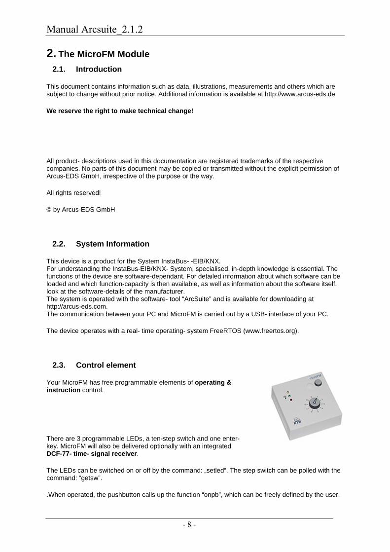
Your MicroFM has free programmable elements of operating & instruction control.
There are 3 programmable LEDs, a ten-step switch and one enter- key. MicroFM will also be delivered optionally with an integrated DCF-77- time- signal receiver.
The LEDs can be switched on or off by the command: „setled“. The step switch can be polled with the command: “getsw”.
.When operated, the pushbutton calls up the function “onpb”, which can be freely defined by the user.
Manual Arcsuite_2.1.2
- 9 -
2.4. DCF-77-Receiver
The integrated DCF-77 time-signal receiver is directed by a program in FORTH code. The code gives you the values for sunrise and sundown over an astronomical clock. In the standard package this code is pre-programmed (eibzeitmaster1.code + eib.tbl).You can also download the code from our homepage (dcf_uhr.zip) onto your computer
2.4.1. Frequency Search
When switching on the receiver, the green LED blinks every second, unless it has been rewritten with another value. This takes place independently of the programming.
The blinking light shows that the DCF-77 signal is being received. After one minute of constant blinking, the controller adjusts to the time received. The blinking then stops and turns into a permanent light. If a dysfunction is received while searching (in the blinking phase), the process will start anew.
2.4.2. Receiving the Time Signal
The reception is dependant on several factors, which may change in the course of the day. These are e.g. machines or other electronic devices in the proximity of the DCF-77 Receiver, weather conditions (sun, rain), nearby radio communication, etc…. However, because the receiver has a built-in clock, an irregular reception is sufficient. If however, reception is very poor or non-existent alltogether, the clock will not be set. The building or its alignment are among the factors determining this. The antenna of the DCF-77 is fitted in the MicroFM module. It should always be positioned in a right angle to the transmitter of the Mainflingen station (Frankfurt on Main). No metal objects, e.g. racks in leightweight construction material, or reinforcements in steel beton buildings should, if possible, be near the receiver. Position the receiver as closely as possible to an opening in the building. It is possible that you will have to search for a location where you can receive the signal. The blinking light indicates that it is being received.
2.4.3. Programming
Through FORTH code the commands „systime“ and „sysdate“ give you access to the received timecode. You can feed this data into your EIB-Net through a short program. “syst” and “sysd” also feed back the information “daylight saving time” in Bit number 24 and “synchronized” in Bit number 25. Beforehand you have to initialize and transfer the required group adresses on the MicroFM module. In our examples these are: Bustime EIB Typ Time send Group address ZB 9/0/0 Busdate EIB Typ Date Send Group address ZB 9/0/1 sonnenunt (sundown) EIB Typ Time Send Group address ZB 9/0/2 sonnenauf (sunrise) EIB Typ Time Send Group address ZB 9/0/3 Please note, the declarations in FORTH are case-insensitive . Transfer the address-table to the MicroFM-Modul and start anew. Afterwards you can transfer the application into the MicroFM-Module and save it with “fsave”. Now you can automatically receive the time and let the time of sunrise and sundown be calculated. To import the Code "eibzeitmaster1.code" into your project, import it with "Import Text".
Manual Arcsuite_2.1.2
- 10 -
2.4.4. Code example
eibzeitmaster1.code : tagnr ( -- Tagnr ) 1 pick 10 + 13 / 3 roll 3 roll 2 + 3055 * 100 / 2 pick 2 * - 91 - + 1 3 roll 4 mod 3 + 4 / - rot * + ; : declination sysd ddate tagnr float 79.35 f- 0.0172 f* sin 0.40954 f* ; : zeitgl sysd ddate tagnr float 2dup 0.033430 f* 0.5474 f+ sin 0.1752 f* 2swap 0.018234 f* 0.1939 f- sin 0.134 f* f+ ; ( PI als constante ) 1.0 atan 4.0 f* 2const pi ( geographische Breite ) 52.5 ( Berlin ) pi f* 180.0 f/ 2const G_Breite ( geographische Länge ) 13.4 ( Berlin ) 15.0 2swap f- 4.0 f* 60.0 f/ 2const L_comp ( Compensation der Länge ) ( Definition Sonnenaufgang/untergang ) -0.0145 sin 2const s_aufunt ( -50 Bogenminuten unterm horizont) : zeitdiff declination 2dup sin G_Breite sin f* s_aufunt 2swap f- 2swap cos G_Breite cos f* f/ acos 12.0 f* pi f/ ; ( Sommerzeit / Winterzeit ) : wochentag ( T M J -- WT ) dup 4 / + swap 1+ 13 * 5 / + + -2 + 7 mod 1+ ; : sommerzeit sysd -24 shift 1 and ; : Sonnenaufgang 12.0 zeitdiff f- zeitgl f+ L_comp f+ sommerzeit 0<> if 1.0 f+ then 2dup fix -rot 60.0 f* fix 60 mod ; : Sonnenuntergang 12.0

Manual Arcsuite_2.1.2
- 11 -
zeitdiff f+ zeitgl f+ L_comp f+ sommerzeit 0<> if 1.0 f+ then 2dup fix -rot 60.0 f* fix 60 mod ; : updtime syst eib.Buszeit eibset sysd eib.Busdatum eibset 3 tstart ; : setdatetime eib.Buszeit eibtx eib.Busdatum eibtx 0 sonnenuntergang 0 ctime eib.sonnenunt eibset 0 sonnenaufgang 0 ctime eib.sonnenauf eibset eib.sonnenunt eibtx eib.sonnenauf eibtx ; : checksync syst -25 shift 0 <> ; : syncloop checksync if 1 tstart 3 tstart setdatetime 0 0 setled else 0 tstart then ; : newsync syst 0x1FFFFFF and setsyst 1 0 setled 2 tstart ; : oninit 0 ['] syncloop 100 tinit 1 ['] syncloop 6000 tinit 2 ['] newsync 360000 tinit 3 ['] updtime 20 tinit 0 tstart newsync ;
Manual Arcsuite_2.1.2
- 12 -
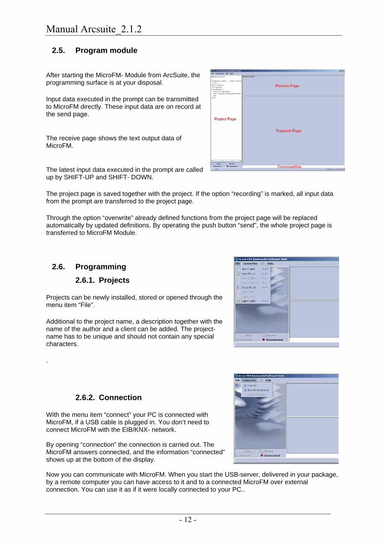
2.5. Program module
After starting the MicroFM- Module from ArcSuite, the programming surface is at your disposal.
Input data executed in the prompt can be transmitted to MicroFM directly. These input data are on record at the send page.
The receive page shows the text output data of MicroFM.
The latest input data executed in the prompt are called up by SHIFT-UP and SHIFT- DOWN.
The project page is saved together with the project. If the option “recording” is marked, all input data from the prompt are transferred to the project page.
Through the option “overwrite” already defined functions from the project page will be replaced automatically by updated definitions. By operating the push button “send”, the whole project page is transferred to MicroFM Module.
2.6. Programming 2.6.1. Projects
Projects can be newly installed, stored or opened through the menu item “File”.
Additional to the project name, a description together with the name of the author and a client can be added. The project- name has to be unique and should not contain any special characters.
.
2.6.2. Connection
With the menu item “connect” your PC is connected with MicroFM, if a USB cable is plugged in. You don’t need to connect MicroFM with the EIB/KNX- network. By opening “connection” the connection is carried out. The MicroFM answers connected, and the information “connected” shows up at the bottom of the display. Now you can communicate with MicroFM. When you start the USB-server, delivered in your package, by a remote computer you can have access to it and to a connected MicroFM over external connection. You can use it as if it were locally connected to your PC..

Manual Arcsuite_2.1.2
- 13 -
2.6.3. EIB Settings
Here you need specialised knowledge about the European Installation Bus. Ask your system- integrator or your EIB service-provider.
2.6.3.1. Import and edit EIB- objects
64 EIB group-addresses can be used. The import of group- addresses is carried out by direct selection from the ETS3 database. Each address- point can also be entered manually and processed separately. If you are working with ArcSuite parallel to ETS, start ArcSuite before ETS.
to create a new EIB-object
to edit an EIB-object
to clear a single EIB-object
to clear the whole EIB-table (EIB.tbl)
to import EIB-Objects from the ETS and to create a new EIB.tbl
To import EIB-objects the path to the EIB-database and the EIB- databank-engine has to be set. (See 1.1 Introduction/Settings)
Caution! When imports are made with this function, all EIB-objects in the EIB-list of the ArcSuite project are deleted.
Choose your EIB project from the ETS. To attach single data points from the ETS, click on “confirm” or “skip” if you want to import each data point separately. To attach the whole list, choose “all”. Please note that the number of group addresses that appear in the list does not exceed the maximum.
importing filtered EIB- Objects
The procedure for importing EIB-objects is similar to that described above. Here you can attach data points to your already existent list, without deleting extant data points. Please note that the number of group addresses that appear in the list does not exceed the maximum. To add new data points, you have to clear up memory space on the list through manually entering delete.
You can choose between several filters.
The selective data- import can be carried out by pressing the button: „Add EIB- objects filtered" out of the ETS over the primary-, secondary- or sub- groups or with the full text search contains object- name.
Input text contents under „object name contains“. Click „ignore case“ if you want to ignore capital lettering. The filter function also takes into account substrings within the object names.

Manual Arcsuite_2.1.2
- 14 -
2.6.3.2. Manual processing/handling EIB- Objects
Polling at start: When the system is started, the data point is scanned. For this the communications- and receiver-flag has to be set.
Send: The elements that are connected with this object can output data to the Bus. The communications flag has to be set .
Receive: The elements that are connected with this object can output data to the Bus. The communications flag has to be set.
Communication: Communication has to be permitted to send or receive. These settings can viewed or changed by double-clicking on the entry of the overview.
2.6.3.3. Physical Address
Under the menu level “Physical Address” you can enter the address of the MicroFM. This address is unique in the EIB/KNX-system. On the “Transmit” level the carried out settings are transferred to the MicroFM. Before you can access the objects, the MicroFM has to be restarted once. (Command “reset” in the command line).

Manual Arcsuite_2.1.2
- 15 -
2.6.4. Command Interface
Enter the commands to your MicroFM into the prompt (command line) line-wise. The answer of the MicroFM appears on the receiving- page. The programming of MicroFM is processed in FORTH- dialect. You can get further information about FORTH, the syntax and about the stack- and heap- use from literature reference (bibliography) and/or the internet. Using this language for MicroFM you have the advantage of its compact, fast code and self-compiling attributes. Functions programmed and commands entered are executed by multitasking. As there exists only one common stack, every function processed in the background has to take care of an empty stack. A short summary of the functions available you will find in the chapter: language- components.
We wish you a lot of fun with your MicroFM
Your Arcus-EDS developing team
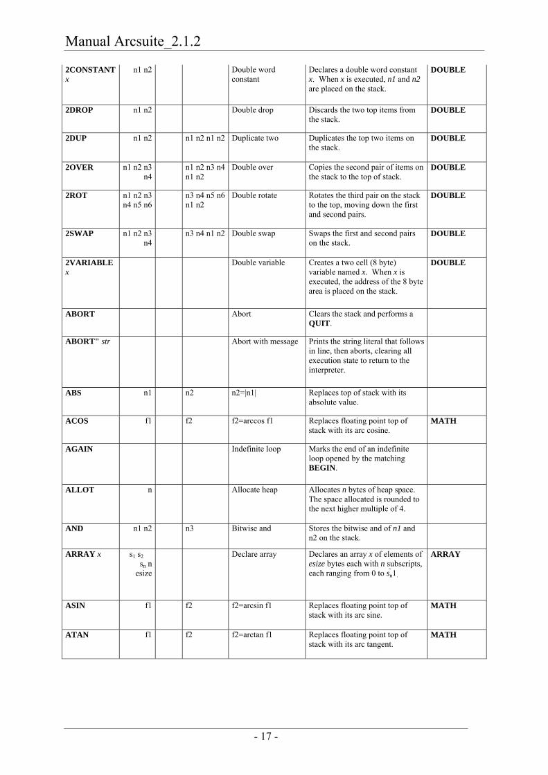
2.6.5. Language Components
All floating- point figures are operated by 8 byte (double). You need 2 stack- or heap- positions for storing. The integer- variables are resolved into 4 bytes. + n1 n2 � n3 n3 = n1 + n2 Adds n1 and n2 and leaves sum on
stack.
- n1 n2 � n3 n3 = n1 n2 Subtracts n2 from n1 and leaves difference on stack.
* n1 n2 � n3 n3 = n1 � n2 Multiplies n1 and n2 and leaves product on stack.
/ n1 n2 � n3 n3 = n1 � n2 Divides n1 by n2 and leaves quotient on stack.
' word � caddr Obtain compilation address
Places the compilation address of the following word on the stack.
, n � Store in heap Reserves four bytes of heap space, initializing it to n.
. n � Print top of stack Prints the number on the top of the stack.
CONIO
.( str � Print constant string Immediately prints the string that follows in the input stream.
CONIO
.S � Print stack Prints entire contents of stack. CONIO
." str � Print immediate string
Prints the string literal that follows in line.
CONIO
: w � Begin definition Begins compilation of a word named w.
; � End definition Ends compilation of word.
< n1 n2 � flag Less than Returns 1 if n1<n2, 0 otherwise.

Manual Arcsuite_2.1.2
- 16 -
<= n1 n2 � flag Less than or equal Returns 1 if n1�n2, 0 otherwise.
<> n1 n2 � flag Not equal Returns 1 if n1�n2, 0 otherwise.
= n1 n2 � flag Equal Returns 1 if n1=n2, 0 otherwise.
> n1 n2 � flag Greater Returns 1 if n1>n2, 0 otherwise.
>= n1 n2 � flag Greater than or equal Returns 1 if n1�n2, 0 otherwise.
? addr � Print indirect Prints the value at the address at the top of the stack.
CONIO
! n addr � Store into address Stores the value n into the address addr.
+! n addr � Add indirect Adds n to the word at address addr.
@ addr � n Load Loads the value at addr and leaves it at the top of the stack.
[ � Set interpretive state Within a compilation, returns to the interpretive state.
['] word � caddr Push next word Places the compile address of the following word in a definition onto the stack.
] � End interpretive state
Restore compile state after temporary interpretive state.
0< n1 � flag Less than zero Returns 1 if n1 less than zero, 0 otherwise.
SHORTCUTC
0<> n1 � flag Nonzero Returns 1 if n1 is nonzero, 0 otherwise.
SHORTCUTC
0= n1 � flag Equal to zero Returns 1 if n1 is zero, 0 otherwise.
SHORTCUTC
0> n1 � flag Greater than zero Returns 1 if n1 greater than zero, 0 otherwise.
SHORTCUTC
1+ n1 � n2 Add one Adds one to top of stack. SHORTCUTA
1- n1 � n2 Subtract one Subtracts one from top of stack. SHORTCUTA
2+ n1 � n2 Add two Adds two to top of stack. SHORTCUTA
2- n1 � n2 Subtract two Subtracts two from top of stack. SHORTCUTA
2* n1 � n2 Times two Multiplies the top of stack by two. SHORTCUTA
2/ n1 � n2 Divide by two Divides top of stack by two. SHORTCUTA
2! n1 n2 addr
� Store two words Stores the two words n1 and n2 at addresses addr and addr+4.
DOUBLE
2@ addr � n1 n2 Load two words Places the two words starting at addr on the top of the stack
DOUBLE
Manual Arcsuite_2.1.2
- 17 -
2CONSTANT x
n1 n2 � Double word constant
Declares a double word constant x. When x is executed, n1 and n2 are placed on the stack.
DOUBLE
2DROP n1 n2 � Double drop Discards the two top items from the stack.
DOUBLE
2DUP n1 n2 � n1 n2 n1 n2 Duplicate two Duplicates the top two items on the stack.
DOUBLE
2OVER n1 n2 n3 n4
� n1 n2 n3 n4 n1 n2
Double over Copies the second pair of items on the stack to the top of stack.
DOUBLE
2ROT n1 n2 n3 n4 n5 n6
� n3 n4 n5 n6 n1 n2
Double rotate Rotates the third pair on the stack to the top, moving down the first and second pairs.
DOUBLE
2SWAP n1 n2 n3 n4
� n3 n4 n1 n2 Double swap Swaps the first and second pairs on the stack.
DOUBLE
2VARIABLE x
� Double variable Creates a two cell (8 byte) variable named x. When x is executed, the address of the 8 byte area is placed on the stack.
DOUBLE
ABORT � Abort Clears the stack and performs a QUIT.
ABORT" str � Abort with message Prints the string literal that follows in line, then aborts, clearing all execution state to return to the interpreter.
ABS n1 � n2 n2=|n1| Replaces top of stack with its absolute value.
ACOS f1 � f2 f2=arccos f1 Replaces floating point top of stack with its arc cosine.
MATH
AGAIN � Indefinite loop Marks the end of an indefinite loop opened by the matching BEGIN.
ALLOT n � Allocate heap Allocates n bytes of heap space. The space allocated is rounded to the next higher multiple of 4.
AND n1 n2 � n3 Bitwise and Stores the bitwise and of n1 and n2 on the stack.
ARRAY x s1 s2 � sn n
esize
� Declare array Declares an array x of elements of esize bytes each with n subscripts, each ranging from 0 to sn1.
ARRAY
ASIN f1 � f2 f2=arcsin f1 Replaces floating point top of stack with its arc sine.
MATH
ATAN f1 � f2 f2=arctan f1 Replaces floating point top of stack with its arc tangent.
MATH

Manual Arcsuite_2.1.2
- 18 -
ATAN2 f1 f2 � f3 f3=arctan f1/ f2 Replaces the two floating point numbers on the top of the stack with the arc tangent of their quotient, properly handling zero denominators.
MATH
BEGIN � Begin loop Begins an indefinite loop. The end of the loop is marked by the matching AGAIN, REPEAT, or UNTIL.
>BODY cfa � pfa Body address Given the compile address of a word, return its body (parameter) address.
BRANCH � Branch Jump to the address that follows in line.
?BRANCH flag � Conditional branch If the top of stack is zero, jump to the address which follows in line. Otherwise skip the address and continue execution.
C! n addr � Store byte The 8 bit value n is stored in the byte at address addr.
C@ addr � n Load byte The byte at address addr is placed on the top of the stack.
C, n � Compile byte The 8 bit value n is stored in the next free byte of the heap and the heap pointer is incremented by one.
C= � Align heap The heap allocation pointer is adjusted to the next four byte boundary. This must be done following a sequence of C, operations.
CLEAR � Clear stack All items on the stack are discarded.
COMPARE s1 s2 � n Compare strings The two strings whose addresses are given by s1 and s2 are compared. If s1 is less than s2, 1 is returned; if s1 is greater than s2, 1 is returned. If s1 and s2 are equal, 0 is returned.
STRING
CONST x n � Declare constant Declares a constant named x. When x is executed, the value n will be left on the stack.
COS f1 � f2 Cosine The floating point value on the top of the stack is replaced by its cosine.
MATH
CR � Carriage return The standard output stream is advanced to the first character of the next line.
CONIO

Manual Arcsuite_2.1.2
- 19 -
CREATE � Create object Create an object, given the name which appears next in the input stream, with a default action of pushing the parameter field address of the object when executed. No storage is allocated; normally the parameter field will be allocated and initialised by the defining word code that follows the CREATE.
DEPTH � n Stack depth Returns the number of items on the stack before DEPTH was executed.
DO limit n � Definite loop Executes the loop from the following word to the matching LOOP or +LOOP until n increments past the boundary between limit1 and limit. Note that the loop is always executed at least once (see ?DO for an alternative to this).
?DO limit n � Conditional loop If n equals limit, skip immediately to the matching LOOP or +LOOP. Otherwise, enter the loop, which is thenceFORTH treated as a normal DO loop.
DOES> � Run-time action Sets the run-time action of a word created by the last CREATE to the code that follows. When the word is executed, its body address is pushed on the stack, then the code that follows the DOES> will be executed.
DROP n � Discard top of stack Discards the value at the top of the stack.
DUP n � n n Duplicate Duplicates the value at the top of the stack.
?DUP n � 0 / n n Conditional duplicate
If top of stack is nonzero, duplicate it. Otherwise leave zero on top of stack.
ELSE � Else Used in an IF—ELSE—THEN sequence, delimits the code to be executed if the if-condition was false.
EXECUTE addr � Execute word Executes the word with compile address addr.

Manual Arcsuite_2.1.2
- 20 -
EXIT � Exit definition Exit from the current definition immediately. Note that EXIT cannot be used within a DO—LOOP; use LEAVE instead.
EXP f1 � f2 f2=ef1 The floating point value on the top of the stack is replaced by its natural antilogarithm.
MATH
F+ f1 f2 � f3 f3=f1+f2 The two floating point values on the top of the stack are added and their sum is placed on the top of the stack.
REAL
F- f1 f2 � f3 f3=f1f2 The floating point value f2 is subtracted from the floating point value f1 and the result is placed on the top of the stack.
REAL
F* f1 f2 � f3 f3=f1�f2 The two floating point values on the top of the stack are multiplied and their product is placed on the top of the stack.
REAL
F/ f1 f2 � f3 f3=f1�f2 The floating point value f1 is divided by the floating point value f2 and the quotient is placed on the top of the stack.
REAL
F. f � Print floating point The floating point value on the top of the stack is printed.
REAL
F< f1 f2 � flag Floating less than The top of stack is set to 1 if f1 is less than f2 and 0 otherwise.
REAL
F<= f1 f2 � flag Floating less than or equal
The top of stack is set to 1 if f1 is less than or equal to f2 and 0 otherwise.
REAL
F<> f1 f2 � flag Floating not equal The top of stack is set to 1 if f1 is not equal to f2 and 0 otherwise.
REAL
F= f1 f2 � flag Floating equal The top of stack is set to 1 if f1 is equal to f2 and 0 otherwise.
REAL
F> f1 f2 � flag Floating greater than The top of stack is set to 1 if f1 is greater than f2 and 0 otherwise.
REAL
F>= f1 f2 � flag Floating greater than or equal
The top of stack is set to 1 if f1 is greater than or equal to f2 and 0 otherwise.
REAL
FABS f1 � f2 f2=|f1| Replaces floating point top of stack with its absolute value.

Manual Arcsuite_2.1.2
- 21 -
FIND s � word flag Look up word The word with name given by the string s is looked up in the dictionary. If a definition if not found, word will be left as the address of the string and flag will be set to zero. If the word is present in the dictionary, its compilation address is placed on the stack, followed by a flag that is 1 if the word is marked for immediate execution and 1 otherwise.
DEFFIELDS
FIX f � n Floating to integer The floating point number on the top of the stack is replaced by the integer obtained by truncating its fractional part.
REAL
(FLIT) � f Push floating point literal
Pushes the floating point literal that follows in line onto the top of the stack.
REAL
FLOAT n � f Integer to floating The integer value on the top of the stack is replaced by the equivalent floating point value.
REAL
FMAX f1 f2 � f3 Floating point maximum
The greater of the two floating point values on the top of the stack is placed on the top of the stack.
FLOAT
FMIN f1 f2 � f3 Floating point minimum
The lesser of the two floating point values on the top of the stack is placed on the top of the stack.
FLOAT
FNEGATE f1 � f2 f2 = f1 The negative of the floating point value on the top of the stack replaces the floating point value there.
FLOAT
FORGET w � Forget word The most recent definition of word w is deleted, along with all words declared more recently than the named word.
HERE � addr Heap address The current heap allocation address is placed on the top of the stack.
I � n Inner loop index The index of the innermost DO—LOOP is placed on the stack.
IF flag � Conditional statement
If flag is nonzero, the following statements are executed. Otherwise, execution resumes after the matching ELSE clause, if any, or after the matching THEN.

Manual Arcsuite_2.1.2
- 22 -
IMMEDIATE � Mark immediate The most recently defined word is marked for immediate execution; it will be executed even if entered in compile state.
J � n Outer loop index The loop index of the next to innermost DO—LOOP is placed on the stack.
LEAVE � Exit DO—LOOP The innermost DO—LOOP is immediately exited. Execution resumes after the LOOP statement marking the end of the loop.
(LIT) � n Push literal Pushes the integer literal that follows in line onto the top of the stack.
LOG f1 � f2 f2=ln f1 The floating point value on the top of the stack is replaced by its natural logarithm.
MATH
LOOP � Increment loop index
Adds one to the index of the active loop. If the limit is reached, the loop is exited. Otherwise, another iteration is begun.
+LOOP n � Add to loop index Adds n to the index of the active loop. If the limit is reached, the loop is exited. Otherwise, another iteration is begun.
MAX n1 n2 � n3 Maximum The greater of n1 and n2 is left on the top of the stack.
MEMSTAT � Print memory status The current and maximum memory usage so far are printed on standard output. The sizes allocated for the stack, return stack, and heap are edited, as well as the percentage in use.
MEMSTAT
MIN n1 n2 � n3 Minimum The lesser of n1 and n2 is left on the top of the stack.
MOD n1 n2 � n3 Modulus (remainder)
The remainder when n1 is divided by n2 is left on the top of the stack.
/MOD n1 n2 � n3 n4 n3 = n1 mod n2, n4 = n1 � n2
Divides n1 by n2 and leaves quotient on top of stack, remainder as next on stack.
NEGATE n1 � n2 n2= n1 Negates the value on the top of the stack.
(NEST) � Invoke word Pushes the instruction pointer onto the return stack and sets the instruction pointer to the next word in line.

Manual Arcsuite_2.1.2
- 23 -
NOT n1 � n2 Logical not Inverts the bits in the value on the top of the stack. This performs logical negation for truth values of 1 (True) and 0 (False).
OR n1 n2 � n3 Bitwise or Stores the bitwise or of n1 and n2 on the stack.
OVER n1 n2 � n1 n2 n1 Duplicate second item
The second item on the stack is copied to the top.
PICK � n2 n1 n0 index
� � n0 nindex Pick item from stack The indexth stack item is copied to the top of the stack. The top of stack has index 0, the second item index 1, and so on.
POW f1 f2 � f3 f3=f1f2 The second floating point value on the stack is taken to the power of the top floating point stack value and the result is left on the top of the stack.
MATH
QUIT � Quit execution The return stack is cleared and control is returned to the interpreter. The stack is not disturbed.
>R n � To return stack Removes the top item from the stack and pushes it onto the return stack.
R> � n From return stack The top value is removed from the return stack and pushed onto the stack.
R@ � n Fetch return stack The top value on the return stack is pushed onto the stack. The value is not removed from the return stack.
REPEAT � Close BEGIN—WHILE—REPEAT loop
Another iteration of the current BEGIN—WHILE—REPEAT loop having been completed, execution continues after the matching BEGIN.
ROLL � n2 n1 n0 index
� � n0 nindex Rotate indexth item to top
The stack item selected by index, with 0 designating the top of stack, 1 the second item, and so on, is moved to the top of the stack. The intervening stack items are moved down one item.
ROT n1 n2 n3 � n2 n3 n1 Rotate 3 items The third item on the stack is placed on the top of the stack and the second and first items are moved down.
-ROT n1 n2 n3 � n3 n1 n2 Reverse rotate Moves the top of stack to the third item, moving the third and second items up.

Manual Arcsuite_2.1.2
- 24 -
S! s1 s2 � Store string The string at address s1 is copied into the string at s2.
STRING
S+ s1 s2 � String concatenate The string at address s1 is concatenated to the string at address s2.
STRING
SHIFT n1 n2 � n3 Shift n1 by n2 bits The value n1 is logically shifted the number of bits specified by n2, left if n2 is positive and right if n2 is negative. Zero bits are shifted into vacated bits.
SIN f1 � f2 Sine The floating point value on the top of the stack is replaced by its sine.
MATH
SQRT f1 � f2 f2 = sqrt f1 The floating point value on the top of the stack is replaced by its square root.
MATH
STATE � addr System state variable The address of the system state variable is pushed on the stack. The state is zero if interpreting, nonzero if compiling.
STRCAT s1 s2 � String concatenate The string at address s1 is concatenated to the string at address s2.
STRING
STRCHAR s1 s2 � String character search
The string at address s1 is searched for the first occurrence of the first character of string s2. If that character appears nowhere in s1, 0 is returned. Otherwise, the address of the first occurrence in s1 is left on the top of the stack.
STRING
STRCMP s1 s2 � n String compare The string at address s1 is compared to the string at address s2. If s1 is less than s2, 1 is returned. If s1 and s2 are equal, 0 is returned. If s1 is greater than s2, 1 is returned.
STRING
STRCPY s1 s2 � Store string The string at address s1 is copied into the string at s2.
STRING
STRING x size � Declare string Declares a string named x of a maximum of size 1 characters.
STRING
STRINT s1 � s2 n String to integer Scans an integer from s1. The integer scanned is placed on the top of the stack and the address of the character that terminated the scan is stored as the next item on the stack.
STRING

Manual Arcsuite_2.1.2
- 25 -
STRLEN s � n String length The length of string s is placed on the top of the stack.
STRING
(STRLIT) � s String literal Pushes the address of the string literal that follows in line onto the stack.
STRING
STRREAL s1 � s2 f String to real Scans a floating point number from s1. The floating point number scanned is placed on the top of the stack and the address of the character that terminated the scan is stored as the next item on the stack.
STRING
SWAP n1 n2 � n2 n1 Swap top two items The top two stack items are interchanged.
TAN f1 � f2 Tangent The floating point value on the top of the stack is replaced by its tangent.
MATH
THEN � End if Used in an IF—ELSE—THEN sequence, marks the end of the conditional statement.
TRACE n � Trace mode If n is nonzero, trace mode is enabled. If n is zero, trace mode is turned off.
TRACE
TYPE s � Print string The string at address s is printed on standard output.
CONIO
UNTIL flag � End BEGIN—UNTIL loop
If flag is zero, the loop continues execution at the word following the matching BEGIN. If flag is nonzero, the loop is exited and the word following the UNTIL is executed.
VAR x � Declare variable A variable named x is declared and its value is set to zero. When x is executed, its address will be placed on the stack. Four bytes are reserved on the heap for the variable's value.
WALKBACK n � Walkback mode If n is nonzero, a walkback trace through active words will be performed whenever an error occurs during execution. If n is zero, the walkback is suppressed.
WALKBACK
WHILE flag � Decide BEGIN�WHILE—REPEAT loop
If flag is nonzero, execution continues after the WHILE. If flag is zero, the loop is exited and execution resumed after the REPEAT that marks the end of the loop.

Manual Arcsuite_2.1.2
- 26 -
WORDS � List words defined Defined words are listed, from the most recently defined to the first defined. If the system supports keystroke trapping, pressing any key will pause the display of defined words; pressing carriage return will abort the listing—any other key resumes it. On other systems, only the 20 most recently defined words are listed.
CONIO
XOR n1 n2 � n3 Bitwise exclusive or Stores the bitwise exclusive or of n1 and n2 on the stack.
(XDO) limit n � Execute loop At runtime, enters a loop that will step until n increments and becomes equal to limit.
(X?DO) limit n � Execute conditional loop
At runtime, tests if n equals limit. If so, skips until the matching LOOP or +LOOP. Otherwise, enters the loop.
(XLOOP) � Increment loop index
At runtime, adds one to the index of the active loop and exits if equal to the limit. Otherwise returns to the matching DO or ?DO.
(+XLOOP) incr � Add to loop index At runtime, increments the loop index by the top of stack. If the loop is not done, begins the next iteration.
SYST � Time Get Systemtime Returns the actual System Time TIME
SETSYST TIME � Set Systemtime Sets the Systemtime TIME
DTIME TIME � WD,H,M,S Decode Time Splits the 32-Bit Timevalue into 4 values: Weekday, Hour, Minute, Second
TIME
CTIME WD H M S
� TIME Code Time Concantenates the values for Weekday, Hour, Minute, Second to one 32-Bit Time-value
TIME
SYSD � Date Get Systemdate Returns the actual System Date DATE
SETSYSD DATE � Set Systendate Sets the Systemdate DATE
DDATE DATE � J M D Decode Date Splits the 32-Bit Datevalue into 3 values: Jear Month and Day
DATE
CDATE J M D � Date Code Date Concantenates the values for year Month and Day to one 32-Bit Date-value
DATE

Manual Arcsuite_2.1.2
- 27 -
TICKS � Ticks Get Systemticks Get the Number of Milliseconds the device is running
SYSTEM
TINIT Nr Function Timeout
� Init Timer Init Timer Nr ( 0 to 15) with timeout and let it execute the function after timeout. Timeout is set in 1/100 second intervalls
TIMER
TSTART Nr � Start Timer Starts the Timer Nr (0 to 15) TIMER
TSTOP Nr � Flag Stop Timer Stops the Timer, Flag is 0 if timer was running, -1 otherwise
TIMER
TCONT NR � Rest Continue Timer Timer is restarted without reset, this function returns the rest amount of time, even if the timer was not stopped before
TIMER
SIGNAL Function � Execute Function asynchron
Send a signal to the system, that the function should be executed
SYSTEM
FSAVE � Save Heap Saves all functions and data defined in the heap into nonvolatile memory , so that the heap is present on the next startup
SYSTEM
FERASE � Clear NVM Clears the nonvolatile memory SYSTEM
SELF � Addr Return Runtime-address
The address of the running Function is pushed on the stack. Used inside a create does> statement, you get the functions adress in the create statement
SYSTEM
FLOAT2DBL 4-Byte-Float
� 8-Byte-Double
Convert Float to Double
EIB-CONVERT
DBL2FLOAT 8-Byte-Double
� 4-Byte-Float
Convert Double to Float
EIB-CONVERT
RESET � Reset System Systemreset and restart SYSTEM
STARTEIB � Activate EIB functions EIB
STOPEIB � Stop EIB functions EIB
EIBGET Objnr � Value Get EIB Value Get the value from object and push it on the stack.
EIB
EIBSET Value, Objnr
� Set EIB value Set the object to value EIB
EIBPOLL OBJNR � Poll EIB value Requests the value from the Bus EIB
EINTX Objnr � Send value Initiates a send of the objects value
EIB
EIS2INT Value � Value Convert 2-Byte- float value to integer
Multiplies the 2-byte float with 100 and makes it integer
EIB-CONVERT
Manual Arcsuite_2.1.2
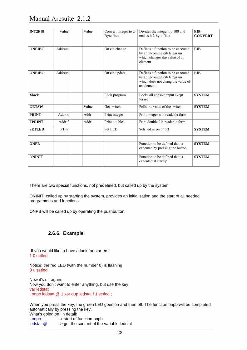
- 28 -
INT2EIS Value � Value Convert Integer to 2-Byte float
Divides the integer by 100 and makes it 2-byte-float
EIB-CONVERT
ONEIBC Address � On eib change Defines a function to be executed by an incoming eib telegram which changes the value of an element
EIB
ONEIBC Address � On eib update Defines a function to be executed by an incoming eib telegram which does not chang the value of an element
EIB
Xlock � Lock program Locks all console input exept ferase
SYSTEM
GETSW � Value Get switch Polls the value of the switch SYSTEM
PRINT Addr n � Addr Print integer Print integer n in readable form
FPRINT Addr f � Addr Print double Print double f in readable form
SETLED 0/1 nr � Set LED Sets led nr on or off SYSTEM
ONPB Function to be defined that is
executed by pressing the button SYSTEM
ONINIT Function to be defined that is executed at startup
SYSTEM
There are two special functions, not predefined, but called up by the system.
ONINIT, called up by starting the system, provides an initialisation and the start of all needed programmes and functions.
ONPB will be called up by operating the pushbutton.
2.6.6. Example
If you would like to have a look for starters: 1 0 setled Notice: the red LED (with the number 0) is flashing 0 0 setled Now it’s off again. Now you don’t want to enter anything, but use the key: var ledstat : onpb ledstat @ 1 xor dup ledstat ! 1 setled ; When you press the key, the green LED goes on and then off. The function onpb will be completed automatically by pressing the key. What’s going on, in detail: : onpb -> start of function onpb ledstat @ -> get the content of the variable ledstat

Manual Arcsuite_2.1.2
- 29 -
1 xor -> exclusive or with 1, the value switches from 0 to 1 dup -> the obtained value is duplicated on the stack. ledstat ! -> the value will be written to the address of ledstat 1 setled -> the duplicated value will be written on led 1 as well (green) ; -> end of definition Now let’s forget the whole thing!! forget ledstat Now let’s switch on/ off the LED governed by the rotary -switch : onpb getsw dup 1 and 0= if 0 else 1 then 0 setled dup 2 and 0= if 0 else 1 then 1 setled 4 and 0= if 0 else 1 then 2 setled ; getsw gets the switch-setting, binary represented by the LEDs, when you press the key. forget onpb deletes all again. Now we try to work with a timer: : ledon 1 0 setled ; : ledoff 0 0 setled ; 0 ' ledoff 100 tinit : onpb ledon 0 tstart ; Operating the pushbutton, the LED goes on for a second. We can recognise the first and second line as functions switching on and off the red LED. In the third line a timer will be initialised (number 0 out of 0 to15) which carries out “ledoff) after 100/100 seconds. (The term “ledoff” gets the runtime-address). In the FORTH line the function onpb switches on the LED and starts the timer (number 0). If the timeout should be governed by the rotary-switch e.g. it is possible to declare the timer as runtime. : onpb ledon 0 ['] ledoff getsw 100 * tinit 0 tstart ; Now the rotary-switch determines the number of seconds. Notice the change (`’) ledoff with which the runtime- address can be determined in functions to functions. Enough about the operating control: forget ledon You bought the device because of the EIB- interface. Now construct a 1 bit group-object of your choice under EIB- settings ( best is a lightthat you can see from where you are). Name it testobj without setting the flags (You don’t want to receive this object, and it should not answer any recalls from the Bus). Transfer your new group- table to the device and carry out a reset. (enter:“ reset”). With the new connection working, the term „connected“ shows up once more. By now your MicroFM should be connected to the EIB/KNX- Bus. : on0 1 eib.testobj eibset eib.testobj eibtx ; on0 Your have switched on your light (lamp). : off0 0 eib.testobj eibset eib.testobj eibtx ; off0 Now it’s off again. EIBset sets the internal group- object and EIBTX sends the information to the Bus.

Manual Arcsuite_2.1.2
- 30 -
To send is one thing, to receive another. Again add a 1 bit group- object (this time a pushbutton) under EIB-settings. Name it pushbutton 1 and set the receive-flag (we watch our flags by our MicroFM) Now again transmit and reset. var ledstat : toggle ledstat @ 1 xor dup ledstat ! 0 setled ; You recognise an acquaintance: the red LED will be switched (turned, shifted). : eibin eib.Taster1 = if toggle then ; ' eibin dup oneibc oneibu You defined a function, which tests if the stack-value at the top corresponds with the object-number of your pushbutton- signals. If this is the case, the LED will be turned and you have passed on the function-address of this function to the call parameter oneibc and oneibu. The function will then be registered for incoming EIB-telegrams (both at changed values and at value-update). When a telegram is coming in, the object-number is written on the stack and the function eibin is carried out. Now everything just needs to be activated. starteib Now you can switch on/off the LED with your pushbutton. stopeib stopeib stops the reception again. If you want everything to function and start up again immediately after a reset, you have to define the start-function oninit. : oninit ['] eibin dup oneibc oneibu starteib ; Until now all is stored in RAM, but has to be transferred to the persistent memory (ROM). fsave Now take a look at the memory capacity: memstat The following output appears: Stack: Curr: 0 Items: 100 0 % Return stack: Curr: 0 Items: 100 0 % Heap: Curr: 49 Items: 2176 2 % Flash: Curr: 192 Items: 8192 2 % 2% of the memory is already used. After a reboot all appears as it was programmed before, and your LED-switch functions without your assistance. With ferase you can delete the persistent memory again. The device starts automatically anew. If you would like to protect the device against unauthorised access, type in xlock, then you have still have console-output, but no command input except ferase. If you make a mistake in the programming and you have no further access because the device says shuts down directly after the start, you can start the device by pressing down the pushbutton. Now delete the bad program with ferase and begin anew.

Manual Arcsuite_2.1.2
- 31 -
2.6.7. Preprocessor
Pre-processor Each text, sent from the project- page, runs through a pre- processor, which recognises the following commands, not passed on to the MicroFM.
#define xx yyy, Any xx occurring later on will be replaced with yyy.
#include filename The file`s filename will be read. The file is searched in relation to the folder microfm/includes.
#........Any line, beginning with #, will be aborted.

Manual Arcsuite_2.1.2
- 32 -
3. MicroVis Module 3.1. Introduction
This document contains information such as data, illustrations, values and others that are subject to change without prior notice. Additional information is available under www.arcus-eds.de.
We reserve the right to make technical changes!
All product- descriptions used in this documentation are registered trademarks of the respective companies. No parts of this document may be copied or transmitted without the explicit permission of Arcus-EDS GmbH, irrespective of purpose or way.
All rights reserved! © by Arcus-EDS GmbH
3.2. System Information
This device is a product for the InstaBus- EIB/KNX- System. Detailed knowledge in depth of the InstaBus- EIB/KNX- System is essential. The functions of the device are software- dependant. For detailed information about which software can be downloaded and which function capacity is then available as well as information about the software itself, have a look at the software details of the manufacturer. It is operated with the software tool „ARC Suite“ and is ready for downloading under http://www.arcus-eds.de
This device works with a real- time operating system FreeRTOS (www.freertos.org).
3.3. Project Administration
In the menu item “file” you find the tools for the project- administration
3.3.1. New Project
A new project demands a unique name and contains further optional instructions.
Under its project- name the project can later be selected or deleted. The entry of the author’s and client’s name or a description is optional. The instruction for the start page enables you to enter the selected background colour as well as the use of a blueprint, which can be selected from any of your blueprints.
If you do not have any blueprints, choose the indication: ”empty” displays.
The settings can be changed under project details at any time.

Manual Arcsuite_2.1.2
- 33 -
3.3.2. Open Project
An option dialog shows up to open your projects.
The projects are displayed under the project name you have chosen.
3.3.3. Delete Project
Displays an option dialog to delete your projects
The projects are displayed under the project name you have chosen
3.3.4. Save Project
Saves the active project with all changes you have made. To transport your projects from one computer to another or to another version of ArcSuite choose the option “export” or “import”.
3.3.5. Save Project As
Saves the active project with all the changes you have made under another name.
3.3.6. Project Properties
Here you can display settings you have made carrying out your project, and change them if necessary.
3.3.7. Export Project
The current project can be packed together in an export- file under a chosen name. You can export it e.g. to another PC or save the current version for the purpose of documentation.
3.3.8. Import Project
An earlier exported project can be imported under a chosen name.
Manual Arcsuite_2.1.2
- 34 -
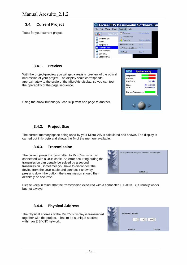
3.4. Current Project
Tools for your current project
3.4.1. Preview
With the project-preview you will get a realistic preview of the optical impression of your project. The display scale corresponds approximately to the scale of the MicroVis-display, so you can test the operability of the page sequence.
Using the arrow buttons you can skip from one page to another.
3.4.2. Project Size
The current memory space being used by your Micro VIS is calculated and shown. The display is carried out in k- byte and shows the % of the memory available.
3.4.3. Transmission
The current project is transmitted to MicroVis, which is connected with a USB-cable. An error occurring during the transmission can usually be solved by a second transmission. Sometimes you have to disconnect the device from the USB-cable and connect it anew by pressing down the button; the transmission should then definitely be accurate.
Please keep in mind, that the transmission executed with a connected EIB/KNX Bus usually works, but not always!
3.4.4. Physical Address
The physical address of the MicroVis display is transmitted together with the project. It has to be a unique address within an EIB/KNX network.

Manual Arcsuite_2.1.2
- 35 -
3.4.5. Print
After selecting and installing your printer you can install information and pages ready for printing on your document as well as the page set-up.
Project information is the information you have declared developing the project.
All pages are marked by default and therefore printed.
Pages, which should not be printed, can be taken out.
Up to 4 pages can be printed on one document page; the set up can be selected. All sides are marked per default and therefore are printed.
Manual Arcsuite_2.1.2
- 36 -
3.4.6. EIB-Settings
To go on you need special knowledge about the European Installation- Bus. You can ask your system- integrator or your EIB- service provider.
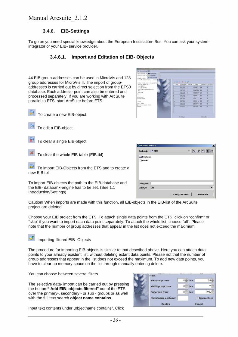
3.4.6.1. Import and Editation of EIB- Objects
44 EIB group-addresses can be used in MicroVis and 128 group addresses for MicroVis II. The import of group- addresses is carried out by direct selection from the ETS3 database. Each address- point can also be entered and processed separately. If you are working with ArcSuite parallel to ETS, start ArcSuite before ETS.
To create a new EIB-object
To edit a EIB-object
To clear a single EIB-object
To clear the whole EIB-table (EIB.tbl)
To import EIB-Objects from the ETS and to create a new EIB.tbl
To import EIB-objects the path to the EIB-database and the EIB- databank-engine has to be set. (See 1.1 Introduction/Settings)
Caution! When imports are made with this function, all EIB-objects in the EIB-list of the ArcSuite project are deleted.
Choose your EIB project from the ETS. To attach single data points from the ETS, click on “confirm” or “skip” if you want to import each data point separately. To attach the whole list, choose “all”. Please note that the number of group addresses that appear in the list does not exceed the maximum.
Importing filtered EIB- Objects
The procedure for importing EIB-objects is similar to that described above. Here you can attach data points to your already existent list, without deleting extant data points. Please not that the number of group addresses that appear in the list does not exceed the maximum. To add new data points, you have to clear up memory space on the list through manually entering delete.
You can choose between several filters.
The selective data- import can be carried out by pressing the button:“ Add EIB- objects filtered" out of the ETS over the primary-, secondary - or sub - groups or as well with the full text search object name contains.
Input text contents under „objectname contains“. Click
Manual Arcsuite_2.1.2
- 37 -
„ignore case“if you want to ignore capital lettering. The filter function also takes into account substrings within the object names.
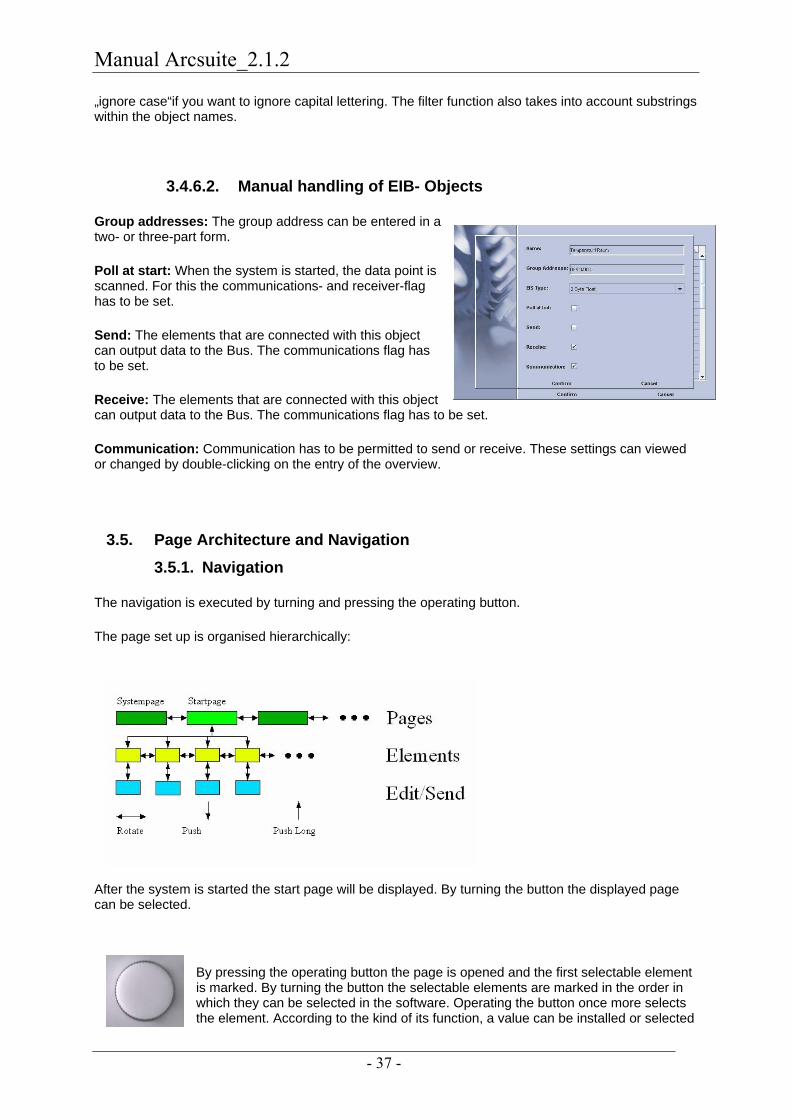
3.4.6.2. Manual handling of EIB- Objects
Group addresses: The group address can be entered in a two- or three-part form.
Poll at start: When the system is started, the data point is scanned. For this the communications- and receiver-flag has to be set.
Send: The elements that are connected with this object can output data to the Bus. The communications flag has to be set.
Receive: The elements that are connected with this object can output data to the Bus. The communications flag has to be set.
Communication: Communication has to be permitted to send or receive. These settings can viewed or changed by double-clicking on the entry of the overview.
3.5. Page Architecture and Navigation 3.5.1. Navigation
The navigation is executed by turning and pressing the operating button.
The page set up is organised hierarchically:
After the system is started the start page will be displayed. By turning the button the displayed page can be selected.
By pressing the operating button the page is opened and the first selectable element is marked. By turning the button the selectable elements are marked in the order in which they can be selected in the software. Operating the button once more selects the element. According to the kind of its function, a value can be installed or selected
Manual Arcsuite_2.1.2
- 38 -
and a telegram can be sent to the Bus.
By pressing the operating button for 2 seconds the level is abandoned and the user reaches one level up.
With the Firmware- version 1.5 and later versions, a page- change can also be initiated by operating a special element.
Complex menu conducts can be realised with this as well. Go to “static text field” – elements, for page design.
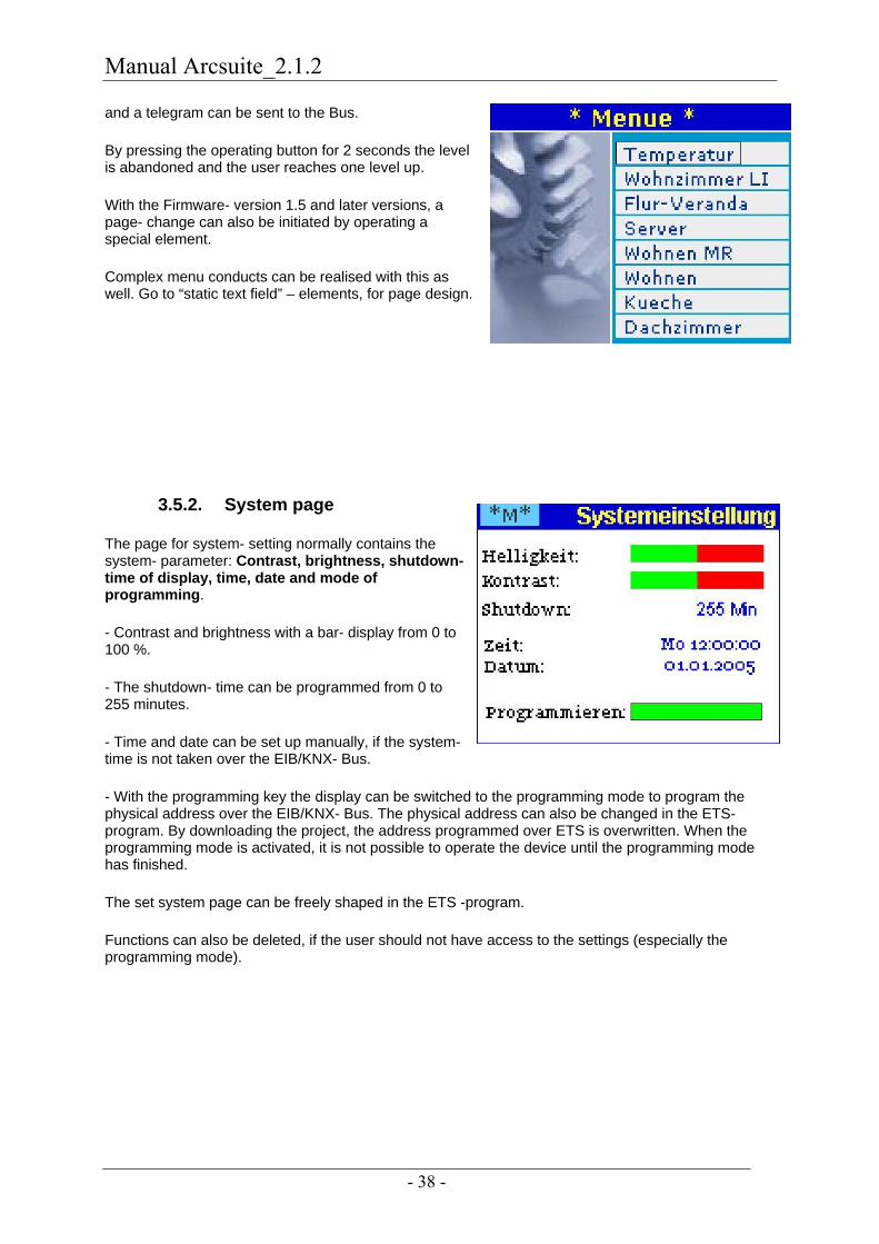
3.5.2. System page
The page for system- setting normally contains the system- parameter: Contrast, brightness, shutdown- time of display, time, date and mode of programming.
- Contrast and brightness with a bar- display from 0 to 100 %.
- The shutdown- time can be programmed from 0 to 255 minutes.
- Time and date can be set up manually, if the system- time is not taken over the EIB/KNX- Bus.
- With the programming key the display can be switched to the programming mode to program the physical address over the EIB/KNX- Bus. The physical address can also be changed in the ETS- program. By downloading the project, the address programmed over ETS is overwritten. When the programming mode is activated, it is not possible to operate the device until the programming mode has finished.
The set system page can be freely shaped in the ETS -program.
Functions can also be deleted, if the user should not have access to the settings (especially the programming mode).
Manual Arcsuite_2.1.2
- 39 -
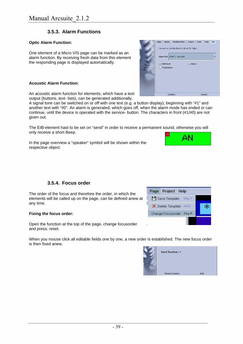
3.5.3. Alarm Functions
Optic Alarm Function:
One element of a Micro VIS page can be marked as an alarm function. By receiving fresh data from this element the responding page is displayed automatically.
Acoustic Alarm Function:
An acoustic alarm function for elements, which have a text output (buttons, text- lists), can be generated additionally. A signal tone can be switched on or off with one text (e.g. a button display), beginning with “#1” and another text with “#0”. An alarm is generated, which goes off, when the alarm mode has ended or can continue, until the device is operated with the service- button. The characters in front (#1/#0) are not given out.
The EIB-element hast to be set on “send” in order to receive a permanent sound; otherwise you will only receive a short Beep.
In the page overview a “speaker” symbol will be shown within the respective object.
3.5.4. Focus order
The order of the focus and therefore the order, in which the elements will be called up on the page, can be defined anew at any time.
Fixing the focus order:
Open the function at the top of the page, change focusorder and press: reset.
When you mouse click all editable fields one by one, a new order is established. The new focus order is then fixed anew.

Manual Arcsuite_2.1.2
- 40 -
Order control:
Clicking on the page with the right side of the mouse opens a pull down menu.
Click: Statistics.
In the statistic the focus sequence is shown and can be changed. It is helpful if you have given your object a name before.
3.6. Elements for Page Layout
Each page is composed of elements. Simple elements, system- elements and EIB/KNX- elements are distinguished. Elements are inserted by selecting the corresponding element in the option “elements” and positioned as you like with the mouse. A dialogue about the details of the respective element pops up automatically. Please notice, that a valid EIB- object has always to be assigned to the EIB/KNX- elements, otherwise the program refuses to save the element.
3.6.1. Properties of the Elements
Some elements have special qualities, which are listed in detail below the elements. Commonly used qualities are shown as details below; they can be set up in the displayed dialogue.
Name:
The name is used for a clear presentation within the different dialogues, but is not required for the transmitted project.
Colours:
The colours for foreground (font) and background can be determined through the colour dialogue. At the button-display the background colour shows the value 0 and the foreground colour the value 1. Colours are determined by a colour option dialogue. Some elements can be drawn transparently: only the foreground will be drawn, e.g. for solid texts over pictures or images.

Manual Arcsuite_2.1.2
- 41 -
Choose colours:
The colours can be chosen from a HSB- or RGB-register.
Position and dimension:
Position and dimension of the element can be determined with the mouse or through the dialogue.
Character set:
By elements with fonts the used character set can be selected.
The installed character sets could be used, but character sets of one’s own could also be produced with Font Editor. Using as few character sets as possible is recommended, as this saves memory space.
Big script fonts need a lot of internal memory, therefore big fonts can also be produced with a zoom of smaller character sets. The respective outlines are not as smooth as the original big character sets. Attention: If the object-size is designed smaller than the current font size, or is placed outside the display screen, it could happen that the field is not shown in its entirety or not shown at all.
In many elements the organisation of the texts can be adjusted. You can choose: left aligned, centre or right aligned. This is especially important for an optimal appearance of varying texts and decimal number displays.

Manual Arcsuite_2.1.2
- 42 -
Dialogue window EIB:
Under the dialogue window “EIB” the data point for this element can be selected, if it is an EIB/KNX- element. The settings for Send options, Push-button-options and Alarm options are optional.
Here choosing the alarm option means that you can define the page to display the reception of the EIB- elements in the foregound.
3.6.2. Static Elements
Static elements are typically used for the optical page design or for marking and short explanations.
3.6.2.1. Static Rectangle
Static rectangles are square coloured elements used for an optical page design. They can be freely positioned and their size freely chosen.
3.6.2.2. Static Text field
As many static texts as you want can be positioned on one page. Position, font- and background- colour as well as character- sets can be chosen freely.
Texts, not selectable by an operating button, can be turned transparent, so that images underneath are not disturbed by a background text.
Focus:
„Allow focus“makes it possible to make your choice with the operating button. This function can be used, to get a focus for turning pages. In detail: If only switching badges with keyboard function are shown on the page, you aren’t offered the option of leaving the page by means of keeping the button pressed longer. For easier navigation on the pages, we recommend first setting up a text button as a first focus
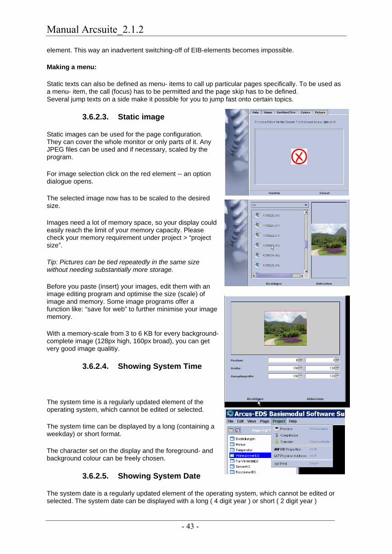
Manual Arcsuite_2.1.2
- 43 -
element. This way an inadvertent switching-off of EIB-elements becomes impossible.
Making a menu:
Static texts can also be defined as menu- items to call up particular pages specifically. To be used as a menu- item, the call (focus) has to be permitted and the page skip has to be defined. Several jump texts on a side make it possible for you to jump fast onto certain topics.
3.6.2.3. Static image
Static images can be used for the page configuration. They can cover the whole monitor or only parts of it. Any JPEG files can be used and if necessary, scaled by the program.
For image selection click on the red element -- an option dialogue opens.
The selected image now has to be scaled to the desired size.
Images need a lot of memory space, so your display could easily reach the limit of your memory capacity. Please check your memory requirement under project > “project size”.
Tip: Pictures can be tied repeatedly in the same size without needing substantially more storage.
Before you paste (insert) your images, edit them with an image editing program and optimise the size (scale) of image and memory. Some image programs offer a function like: “save for web” to further minimise your image memory.
With a memory-scale from 3 to 6 KB for every background- complete image (128px high, 160px broad), you can get very good image qualitiy.
3.6.2.4. Showing System Time
The system time is a regularly updated element of the operating system, which cannot be edited or selected.
The system time can be displayed by a long (containing a weekday) or short format.
The character set on the display and the foreground- and background colour can be freely chosen.
3.6.2.5. Showing System Date
The system date is a regularly updated element of the operating system, which cannot be edited or selected. The system date can be displayed with a long ( 4 digit year ) or short ( 2 digit year )

Manual Arcsuite_2.1.2
- 44 -
format. The character set to display as well as the foreground colour and background colour can be freely chosen.
3.6.3. System Elements
System- elements are elements for setting system details. Typically they are summarised on one page, the system- page. None of the elements may be available, often some are useless, or the user- access is not desirable.
A typical system page:
3.6.3.1. System time
The system time is an element updated constantly in the operating process. Time and date can be adjusted manually if you don't fetch the system time over the EIB/KNX Bus.
The system- time can be displayed by a long (containing a weekday) or short format. The character- set to display can be chosen freely.

Manual Arcsuite_2.1.2
- 45 -
3.6.3.2. System date
The system- date is a regularly updated element of the operating system, which cannot be edited or selected. The system- time can be displayed with a long (containing a weekday) or short format. The system- date can be displayed with a 4- or 2 digit date. The character- set to display can be freely chosen.
3.6.3.3. Standby Timeout:
With the system- element „time standby“ you can adjust the time, after which the monitor and the background light of an inactive appliance should be switched off. The value can vary from 1 to 255 minutes. Character- set, colours, adjustment and position can be set.
3.6.3.4. Programming the Physical Address
To program the physical address with a dummy- application of ETS, the Micro VIS- display has to be switched to the programming- modus with the operating button “programming physical address”. By operating the programming- element, the LCD display at the ETS is in the programming- modus. It cannot be operated any more, all functions are stopped. The physical address is also transmitted with the USB download (look at „actual/ current project”), an existing ETS- programming will be overwritten and has to be repeated. At the menu- item “physical address” the appropriate address has to be installed. The physical address will be transmitted anew with each USB download.
3.6.3.5. Contrast and Brightness
With these elements the user has the possibility to adapt brightness and contrast of the display to his requirement. Foreground and background colours of the element-details define the colours of the left and right side of the bar- display.

Manual Arcsuite_2.1.2
- 46 -

Manual Arcsuite_2.1.2
- 47 -
3.6.4. EIB/KNX Elements
EIB/KNX- elements are elements for display and setting of values in the EIB/KNX- Bus system. These elements offer the appropriate group- address by choice.
The field “editing / sending “has to be activated, if the element should be selectable on the page and a value can be sent to the Bus. If the field “alarm- function” is active, the page of this element is called up at value- change automatically. The field “pushbutton- function” enables operating buttons to send a 1 by pressing the field, a 0 by releasing the field.

Manual Arcsuite_2.1.2
- 48 -
3.6.4.1. Switches and Buttons
Operating- and pushbutton- areas can be distinguished in the object- setting through the field “pushbutton- function”.
Operating- buttons change their value from 0 to 1 by each operation.
Pushbuttons send a 1 when pressed and a 0 by release
.
The function “long pressing” is deactivated at the pushbutton. For detail: If you exclusively work with push-button functions on the side, you should put a static text with focus on the side to leave by "pushing for a long time".
Depending on the operating state the colour of the element changes between fore - and background- colour. The text-setting “font always black” or the setting “font in a complementary colour” can be selected. Complementary colour refers to the fore- and background colours.
3.6.4.2. Dimmer
Dimmer elements can only be connected with a 4 bit dimmer object. By selecting an object, text and colours can change in accordance with the settings. Turning the rotary- switch initiates sending the dimmer value directly, left >dimmer down, right< dimmer up.

Manual Arcsuite_2.1.2
- 49 -
3.6.4.3. Values
Value text elements show values of a data-point in clear (e.g.”25.40° C”).
Details of the value elements are character set, alignment, position, colours and units. The unit is attached at the number- value and aligned with it.
The orientation of value displays can be left- adjusted, centred or right- adjusted to show changing display lengths optimally. The effect of a different text length on the optical impression can be tested through changing the length in the pop up menu between “long value” and “short value”.
3.6.4.4. Lists of Pictures and Values
An image list is an allocation list between images and object values. The object values are of threshold- value character. In the following case the first image is shown from 10.00, the second from 20.00 and so on.
If a list contains only one element, the appropriate value is sent immediately when operated (no choice available). This can be used for single telegrams (send by pressing “1”). If a list contains two elements, it is converted (switched) directly, when operated.
Image lists can only be used for objects with a 2 byte data capacity.
3.6.4.5. Lists of Caption and Values
A text list is an allocation list between text and object values. The object values have a threshold value character. In the following case the text “sub 0” will be displayed from -40. 00, the text “cold“from 0. 00 and so on.
If a list contains only one element, the value will be sent immediately (no choice).
Text lists can be used only for objects with up to 2 byte data capacity.

Manual Arcsuite_2.1.2
- 50 -
3.6.4.6. Room temperature-thermostat (RTR)
The room temperature thermostat (controller) represents the state of RTR symbolically. The following symbols are integrated:
- Present, absent
- Night standby, frost/ heat prevention
- Heating- or cooling service
- Alarm- and block function
General controller, 1 byte
Bit 0: 1: comfort- service active
Bit 1: 1: standby- service active
Bit 2: 1: night- service active
Bit 3: 1: frost/heat- service active
Bit 4: 1: thermostat blocked
Bit 5: 1: heating; 0: cooling
Bit 6: 1: thermostat not active
Bit 7: 1: frost- alarm

Manual Arcsuite_2.1.2
- 51 -
3.6.4.7. Value Bars
Value- Bars are horizontal and vertical.
Value bars are displays and buttons with selectable colours and minimum- maximum details.
If the value- bar has a send function you can choose: sending by confirmation (only once) or by rotation. Detail: Direct dimming hereby becomes possible through a byte value.
The indication: step-number shows how many rotation steps are located between the minimum and maximum value. The encoder can be tuned to the habits of the customer with the desired precision.

Manual Arcsuite_2.1.2
- 52 -
3.6.5. MicroVis II Functions
MicroVis2-Logic Module: Online Documentation The MicroVIS2-Logic is an extension to the MicroVis. All elements and functions available in MicroVis are available in MicroVIS2-Logic as well.
Additional Elements and Extensions:
- Up to 128 Group addresses - 128KByte Memory for pages, images and fonts. - Freely programmable due to integration of the logic elements of the MicroFM Module with up
to 48KByte of memory for code and data. - User functions, timers, security PIN as well as scene management are additionally available
elements.
3.6.5.1. Selection
Use choice to access MicroVis II elements. Please use the right mouse key only to make changes in the properties. This prevents an inadvertent displacement of the objects.
3.6.5.2. User functions
Introduction
A User function is a virtual element that is programmed by the user in the programming language FORTH and that can be placed anywhere on any page in a project.
Under the name you’ve given to this element there is a function created in the FORTH-logic module. With this function you can design your own programs interactively, assume the EIB-Bus input and operating button, as well as having the results shown on your display.
Set parameters like position, colour and character set are available in this function.
Without corresponding programming this element is not visible and has no function.
Additional information about the program can be obtained from Arcus-EDS on demand.
Sequence
First read the help file for the MicroFM module. All functions are explained there in detail.
Generate or import a FORTH code with the ArcSuite-tool MV2Logic (obtainable on the main page of ArcSuite) and send it to the connected and ready-to-receive MicroVis II through the USB-connection.
Open your project, which you have already created in MicroVis II, in MV2Logic (e.g.: “diagram”).
Import the desired code by text (e.g.:”diagram code”) or write it directly into the send window.
Through connect/connection make a connection to the attached USB cable.
Write “ferase” directly into the entry line, and confirm by pressing enter. Now The Logic memory is deleted. Generate a new connection.

Manual Arcsuite_2.1.2
- 53 -
Click send to download the code. Then type in “fsave” and confirm by pressing enter. Now generate a new connection.
Place a user function in the desired size on the page of your MicroVis II. Under properties you can name the user function after the name of the used code. After a complete reset (EIB and USB connection have to disconnected) the function is visible on your display.
Label
With the name that you enter here, you can generate a data structure that you can access at a later time.
E.g.: You have labelled the FORTH code “diagram” and sent it to your MicroVis II through the FM II module. To call up this FORTH-program, you have to put in the name “diagram” under labels.
3.6.5.3. Timer
Timers are elements that can automatically do some actions like sending data to the Bus or recalling scenes at user definable times.
The preset time can be changed on the device, and the timer can be activated or deactivated by the user. The user can also change the timer through the display. If necessary this function can be protected against unauthorised access through a password. (See safety pin 3.6.5.4)
- Character set
The size of the timer shown on your display can be chosen in character set.
- Format
Here you can choose between a long and short format.
Short format: the timer is a day timer and only evaluates the daytime.
Long format: The timer is a week timer and also evaluates weekdays.
- EIB
Choose the data object to be sent, e.g. the lamp that is to be switched on or off.
- Activating the Timer
Enter the action that is to be carried out after the timecyle has expired. You can send data points or recall scenes.

Manual Arcsuite_2.1.2
- 54 -
- Selection field
Sending the data field: An assigned value is sent to the chosen EIB object in the EIB folder.
Scene “label”: If you have configured a scene to your project the name with which you have labelled it will appear in the chosen scene.
Active: Here the timer is activated. This can also be done on the display of the user. Activate the display timer on the square point.
Weekday and time: Enter the default-value here. This can be changed by the user on the display. You can activate the time of day directly and the weekday through underlining.
Value to be sent: A value corresponding to the EIB-object can be selected here.
3.6.5.4. Security PIN
The use of a security pin enables the user to protect certain objects on a page through a password. The password protection is focus oriented, i.e. all objects in the focus sequence standing behind the safety pin are protected through a password. If a page is to be protected in its entirety, the pin focus has to be entered at the beginning. If only an object on the page is to be protected, enter the password at the end of the page. The user has to enter the correct pin code on the display, and activates it by pressing it.
- Pin:
The default value is „12345“and can be given out with ArcSuite.
3.6.5.5. Scene Management
Define, recall or save scenes with this element. The data points to be used are selected in scene definitions, furthermore the values that are used in the scene after a project download are shown. These can be given out anew in operation through “save scene”. Use “scene recall” if the scene is to be used more than once in your project. Scenes are referenced through their label.

Manual Arcsuite_2.1.2
- 55 -
- Text:
Here you can enter the text that appears on the button for the allocated scene. The text is not visible in the case of a picture object.
- Picture:
The function “recall scene x” and “save scene x” can be allocated as a picture to the button function.
- Data points:
Choose the type of scene element. The data points and the values of the scene definition to be sent are set here. The values can be overwritten with the function “save scene”.
- Selection field:
Scene definition with recall: here you can choose EIB-objects that you want to recall or save from a moment of the scene. Assume the allocated values during the project download as default values. These can be changed by the user.
3.7. Services and Suggestions
Send your suggestions and wishes to: [email protected]
Services: If you are interested in our services for the realisation of an actual project, we are happy to make you an offer.
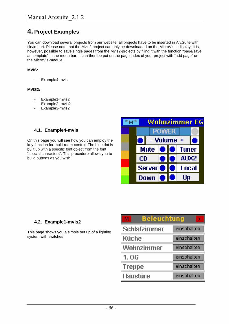
Manual Arcsuite_2.1.2
- 56 -
4. Project Examples
You can download several projects from our website: all projects have to be inserted in ArcSuite with file/import. Please note that the Mvis2 project can only be downloaded on the MicroVis II display. It is, however, possible to save single pages from the Mvis2-projects by filing it with the function “page/save as template” in the menu bar. It can then be put on the page index of your project with “add page” on the MicroVis-module.
MVIS:
- Example4-mvis
MVIS2:
- Example1-mvis2 - Example2 -mvis2 - Example3-mvis2
4.1. Example4-mvis
On this page you will see how you can employ the key function for multi-room-control. The blue dot is built up with a specific font object from the font “special characters”. This procedure allows you to build buttons as you wish.
4.2. Example1-mvis2
This page shows you a simple set up of a lighting system with switches
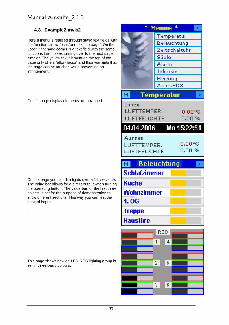
Manual Arcsuite_2.1.2
- 57 -
4.3. Example2-mvis2
Here a menu is realised through static text fields with the function „allow focus“and “skip to page”. On the upper right hand corner is a text field with the same functions that makes turning over to the next page simpler. The yellow text element on the top of the page only offers “allow focus” and thus warrants that the page can be touched while preventing an infringement.
On this page display elements are arranged.
On this page you can dim lights over a 1-byte value. The value bar allows for a direct output when turning the operating button. The value bar for the first three objects is set for the purpose of demonstration to show different sections. This way you can test the desired haptic.
.
This page shows how an LED-RGB lighting group is set in three basic colours.
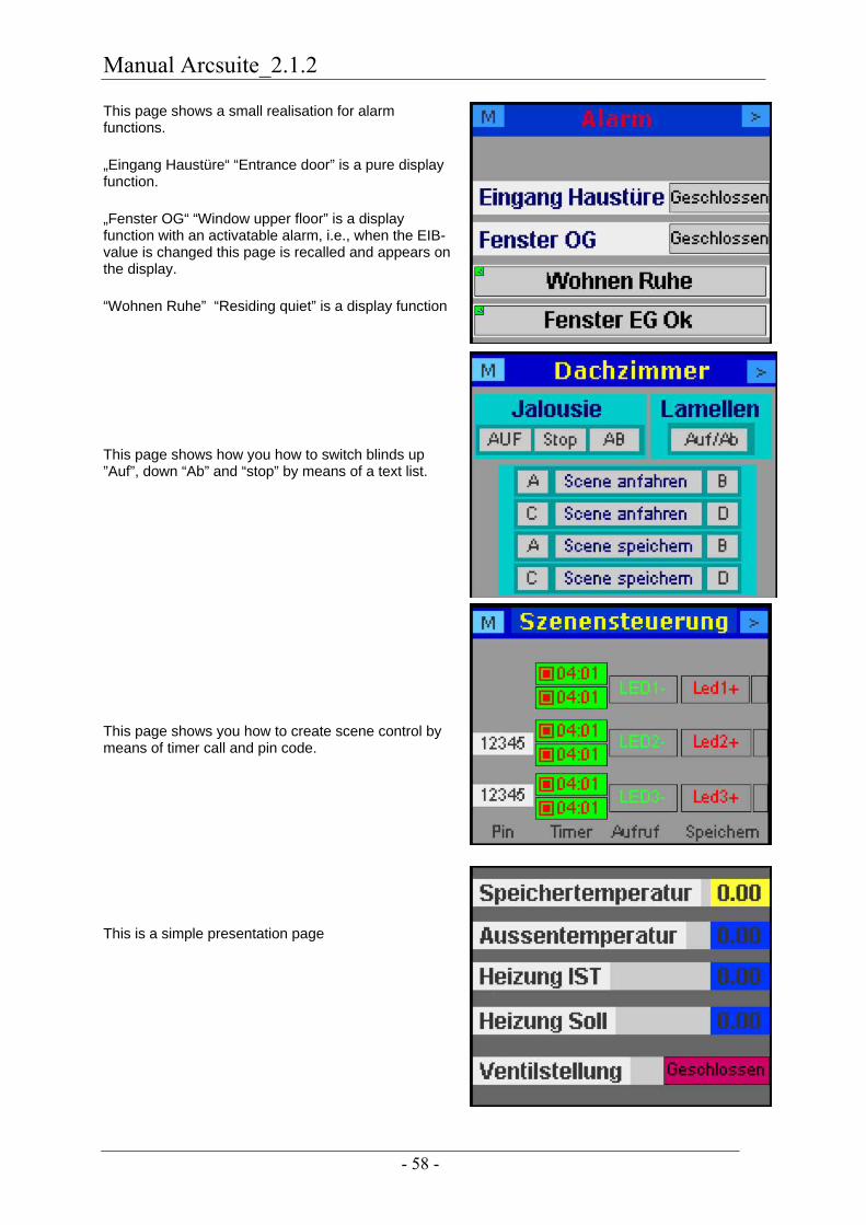
Manual Arcsuite_2.1.2
- 58 -
This page shows a small realisation for alarm functions.
„Eingang Haustüre“ “Entrance door” is a pure display function.
„Fenster OG“ “Window upper floor” is a display function with an activatable alarm, i.e., when the EIB-value is changed this page is recalled and appears on the display.
“Wohnen Ruhe” “Residing quiet” is a display function
This page shows how you how to switch blinds up ”Auf”, down “Ab” and “stop” by means of a text list.
This page shows you how to create scene control by means of timer call and pin code.
This is a simple presentation page

Manual Arcsuite_2.1.2
- 59 -
This page shows you a simple timer structure

Manual Arcsuite_2.1.2
- 60 -
5. Products
5.1. Funktionsmodul MicroFM-Modul
The 50 MHz arm processor permits fast 32 bits upright operations and 64 bits of floating point calculations. It is programmed in a FORTH dialect. A self-compiling interpreter of command lines produces a compact and fast code.
No compiling of programs is necessary. Any defined function is immediately available.
Functions:
- 8 Kbytes RAM-loft for programs and data
- DCF-77 real time hours for precise time controls
- 16 programmable timers with a 1/100 sec dissolution - programs and data can be stored permanently in flash - 3 free programmable LED's - 1 ten-step switch evaluable through programs - 1 push-button for starting a self- defined function customised
- for EIB communication, user elements, the date and time for individual EIB/KNX solutions adapted especially (PWM, ad transducer, serial interface, digital one/exits).
- up to 64 EIB addresses supply USB or EIB, no help tension required, programming with ArcSuite software.
5.2. LCD-Color-Display MicroVis
Arcus-EDS MicroVis I with coloured LCD-graphic display, interactive navigation, jog and push button and acoustic alarm.
The LCD display is used for operating, displaying, monitoring and reporting in EIB/KNX systems. It is intended to serve visualisation and operation in the central part of a building. It is compatible with most series of switch programs (e.g. Gira, Jung, Merten standard 55). It is mounted on a standard flush-mounting box. No external electricity is needed.
Manual Arcsuite_2.1.2
- 61 -
MicroVis has a freely programmable graphic display with background lighting (160x128 pixels). Navigation is through jog and push button. Start up and parameterization with the graphic java-based software-tool “ArcSuite” through a mini-USB cable.
Graphic:
- free design of page contents - 32 elements can be defined free in size and position - The number of pages is limited only by the internal memory space (31kB). - Different character fonts, font size, editable fonts - Attachment of jpg-graphics as background picture for representation elements - Freely programmable surfaces and text elements - Freely programmable EIB-elements for buttons, dimmers, etc - Freely editable menue structure with skip function - System settings for contrast, brightness, standby-time EIB-elements: - Up to 44 group addresses through polling with start - 17 EIS-types incl. 14byte ASCI-character string - Direct dimming function with rotating operating button - Assignment of pictures as value elements - Assignment of text as value elements - Horizontal, vertical value bars - Value bars regulable with rotating knob (free number of steps) - dimming through stop telegram - Buttons as switch or key elements with stop telegram - System time/system date - All EIS-types callable as alarm function - Skip to relevant page in the event of an alarm call - Acoustic alarm freely programmable - Filtered acceptance of group addresses from the ETS Technical data: - Supply: directly on the EIB-Bus, DC 24V, approx. 10mA, no auxiliary voltage necessary - No Bus-coupling necessary - USB-port on the side (covered by the design frame) - Standard flushed-mounting switch box - Environment temperature: storage by –5 C° to + 60 C°, operate by –5 C° to + 55 C° - Dimensions: W x H x L, 55 x 55 x 22 mm without design frame - Safeguard: IP20 - Available colours: white, charcoal grey, charcoal grey with V2A-aperture, other colours available on request. Mounting: - The metal frame delivered with your package is mounted onto the standard flushed-mounting box - The MicroVis is stuck onto the metal frame. An additional design frame is necessary - 1-, 2-, or more frames can be set up Delivery includes a frame for mounting, USB-cable and ArcSuite software
Manual Arcsuite_2.1.2
- 62 -
5.3. LCD-Colour - Display MicroVis II
The MicroVis II is identical in construction with the MicroVis I and contains entirely the same functions. It differs only in internal memory size and built-in firmware.
Extended memory area:
- 128 group addresses - 128 Kbytes memory size for use e.g. 24 jpg. pictures for one project
The new firmware for the MicroVis II has the following additional functions:
- User function
This function allows you to independently generate objects that are not slated for ArcSuite, e.g. extra switches, logic functions or graphic applications (diagrams)
- Scene control
Different EIB-data points can be recalled and saved by a button that has the respective values assigned to it.
- Timer functions
EIB-data points and scenes can be recalled on a day and week timer
- PIN code
different objects on a page in the project can be protected with a password

Manual Arcsuite_2.1.2
- 63 -
6. Fitting
6.1. Fitting FM-Modul
The function module is screwed onto a 68mm box. The function module is supplied as an AP-apparatus by the EIB-Bus from behind. ArcSuite is programmed through the USB-plug on the upper left hand/right hand. The programming of the physical interface over ETS is done through the button on the circuit board (see picture).
6.1.1. Opening of the FM-Modul
Loosen the cover of the screw on the upper part of the apparatus and unscrew covering cap. In the “FM-module DC77” version the DC-77 receiver is fitted in the covering of the screw top. Open the connected screw top covering carefully, without interrupting the connection to the four-pole plug on the circuit board. You can now connect the EIB-Bus to the mini-USB plug through an EIB-clamp and press the programming key.
6.1.2. Plastic Foil
You can use the plastic foil on the function module for inscription. If you want to make your own foil, we (www.arcus-eds.de) can make the file available to you.
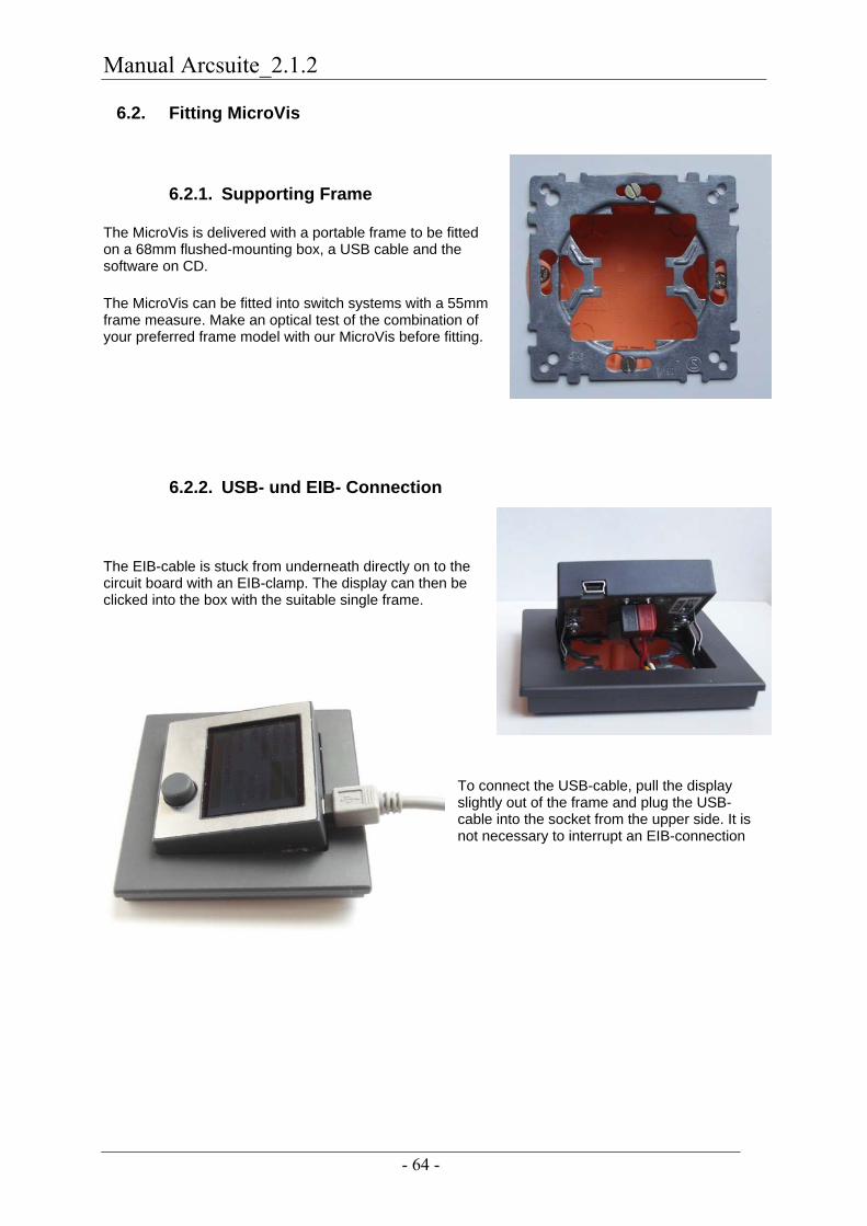
Manual Arcsuite_2.1.2
- 64 -
6.2. Fitting MicroVis
6.2.1. Supporting Frame
The MicroVis is delivered with a portable frame to be fitted on a 68mm flushed-mounting box, a USB cable and the software on CD.
The MicroVis can be fitted into switch systems with a 55mm frame measure. Make an optical test of the combination of your preferred frame model with our MicroVis before fitting.
6.2.2. USB- und EIB- Connection
The EIB-cable is stuck from underneath directly on to the circuit board with an EIB-clamp. The display can then be clicked into the box with the suitable single frame.
To connect the USB-cable, pull the display slightly out of the frame and plug the USB-cable into the socket from the upper side. It is not necessary to interrupt an EIB-connection