clima controller - descargas.futurasmus-knxgroup.org
TRANSCRIPT
1
Clima controllerTemperature Controller
Climate control in style.
SIMPLY INIMITABLE. 2
SUMMARY
1. Functional specification and info
2. Feautures control panel version “british” 3. Feautures control panel version “EU 503”
4. Diagrams climate control (fig. 1)
5. Configuration
1a. Season Change 1b. Selection of system type - refer to diagram (fig. 1) 1c. Address of ICU700 Device
6. BUS Connection
7. Multi-zone temperature, CLIMA CONTROL addressing
8. iPad functionalities and Timer setup
3
4
5
6
5
7 88
9
10
11
SIMPLY INIMITABLE. 3
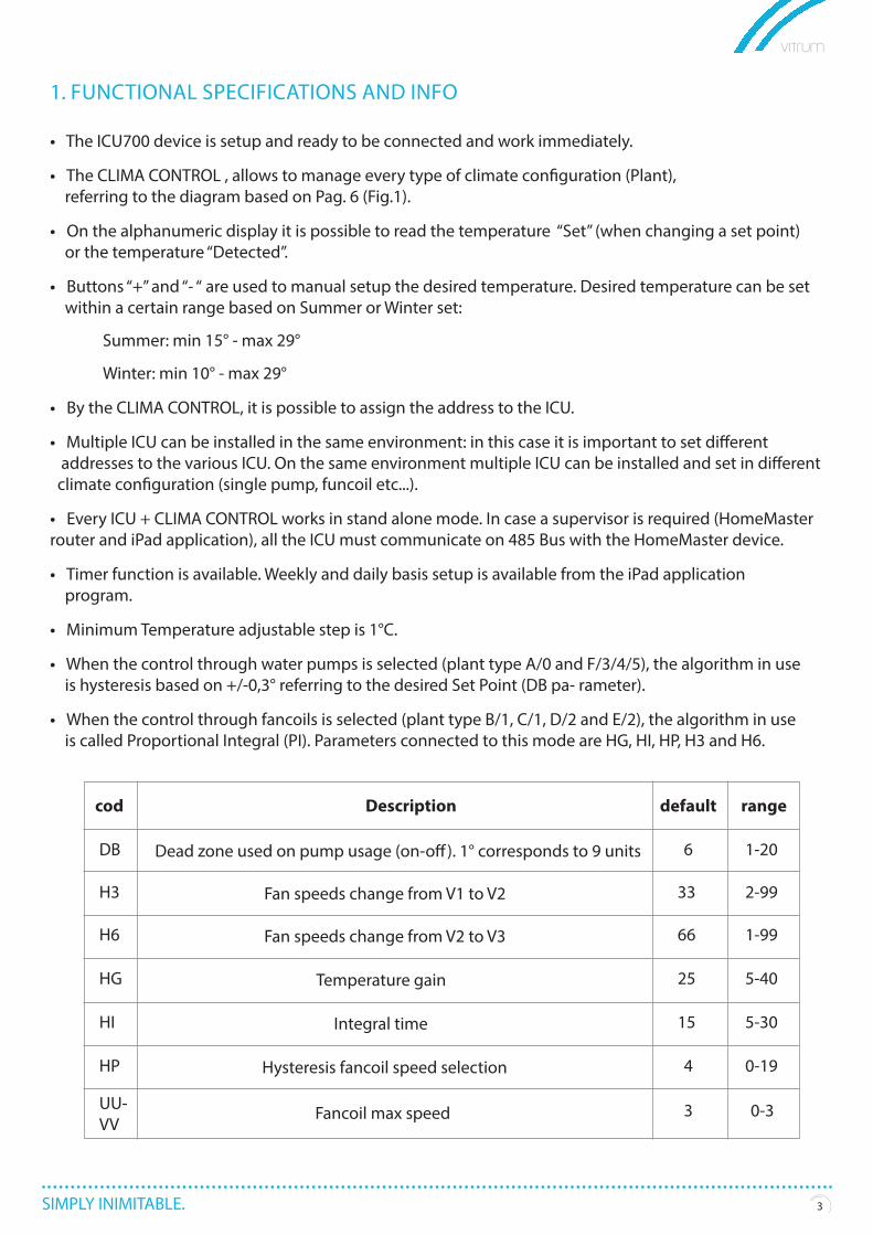
1. FUNCTIONAL SPECIFICATIONS AND INFO
• The ICU700 device is setup and ready to be connected and work immediately.
• The CLIMA CONTROL , allows to manage every type of climate configuration (Plant), referring to the diagram based on Pag. 6 (Fig.1).
• On the alphanumeric display it is possible to read the temperature “Set” (when changing a set point) or the temperature “Detected”.
• Buttons “+” and “- “ are used to manual setup the desired temperature. Desired temperature can be set within a certain range based on Summer or Winter set:
Summer: min 15° - max 29°
Winter: min 10° - max 29°
• By the CLIMA CONTROL, it is possible to assign the address to the ICU.
• Multiple ICU can be installed in the same environment: in this case it is important to set different addresses to the various ICU. On the same environment multiple ICU can be installed and set in different climate configuration (single pump, funcoil etc...).
• Every ICU + CLIMA CONTROL works in stand alone mode. In case a supervisor is required (HomeMaster router and iPad application), all the ICU must communicate on 485 Bus with the HomeMaster device.
• Timer function is available. Weekly and daily basis setup is available from the iPad application program.
• Minimum Temperature adjustable step is 1°C.
• When the control through water pumps is selected (plant type A/0 and F/3/4/5), the algorithm in use is hysteresis based on +/-0,3° referring to the desired Set Point (DB pa- rameter).
• When the control through fancoils is selected (plant type B/1, C/1, D/2 and E/2), the algorithm in use is called Proportional Integral (PI). Parameters connected to this mode are HG, HI, HP, H3 and H6.
cod
DB Dead zone used on pump usage (on-off). 1° corresponds to 9 units 6 1-20
H3 Fan speeds change from V1 to V2 33 2-99
H6 Fan speeds change from V2 to V3 66 1-99
HG Temperature gain 25 5-40
HI Integral time 15 5-30
HP Hysteresis fancoil speed selection 4 0-19
UU-VV
Fancoil max speed 3 0-3
Description default range
SIMPLY INIMITABLE. 4
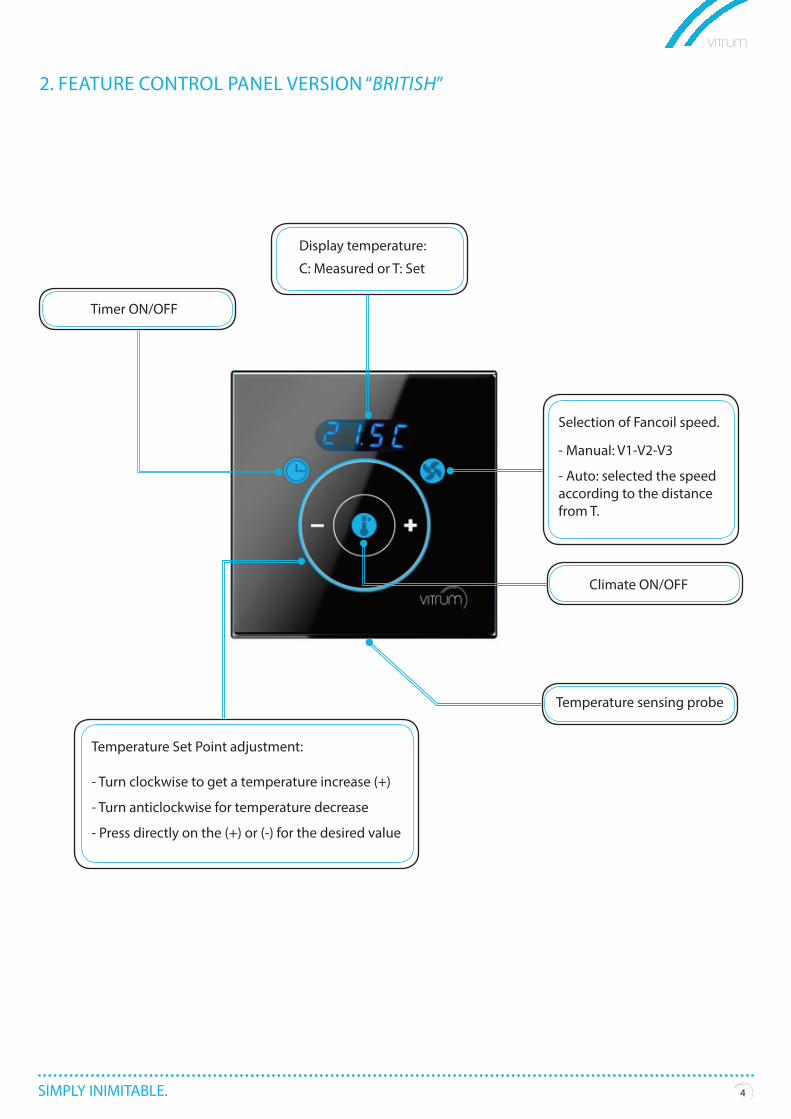
2. FEATURE CONTROL PANEL VERSION “BRITISH”
Temperature Set Point adjustment:
- Turn clockwise to get a temperature increase (+)
- Turn anticlockwise for temperature decrease
- Press directly on the (+) or (-) for the desired value
Timer ON/OFF
Climate ON/OFF
Temperature sensing probe
Display temperature:
C: Measured or T: Set
Selection of Fancoil speed.
- Manual: V1-V2-V3
- Auto: selected the speed according to the distance from T.
SIMPLY INIMITABLE. 5
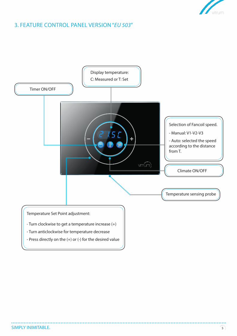
3. FEATURE CONTROL PANEL VERSION “EU 503”
Timer ON/OFF
Temperature Set Point adjustment:
- Turn clockwise to get a temperature increase (+)
- Turn anticlockwise for temperature decrease
- Press directly on the (+) or (-) for the desired value
Climate ON/OFF
Temperature sensing probe
Display temperature:
C: Measured or T: Set
Selection of Fancoil speed.
- Manual: V1-V2-V3
- Auto: selected the speed according to the distance from T.
SIMPLY INIMITABLE. 6
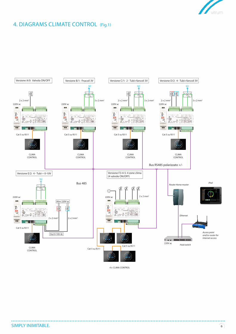
4. DIAGRAMS CLIMATE CONTROL (Fig.1)
M
M
M MV1
V1
N2N2N2
N2
V1 V1V3
V3
V3 V3
V2
V2
Cat 5 su RJ11Cat 5 su RJ11
Cat 5 su RJ11
Ethernet
Router Home master
Hub/switch
Access point and/or router for Internet access
Cat 5 su RJ11Cat 5 su RJ11
Cat 5 su RJ11 Cat 5 su RJ11
CLIMACONTROL
CLIMACONTROL
CLIMACONTROL
CLIMACONTROL
CLIMACONTROL
CLIMA CONTROL4 x
V2 V2
220V ac
220V ac
220V ac
220V ac
220V ac220V ac
3 x 2 mm2 3 x 2 mm2 2 x 2 mm22 x 2 mm22 x 2 mm2
2 x 2 mm2
2 x 2 mm2
Bus 485
Bus RS485 polarizzato +/-
2 x 2 mm2
3 x 2 mm2
220V ac
Alim 220V ac
Out 0-10V dc
Versione E/2: 4 - Tubi = 0-10V
Versione A/0: Valvola ON/OFF Versione B/1: Fnacoil 3V Versione C/1: 2 - Tubi+fancoil 3V Versione D/2: 4 - Tubi+fancoil 3V
Versione F3-4-5: 4 zone clima(4 valvole ON/OFF)
iPad
SIMPLY INIMITABLE. 7
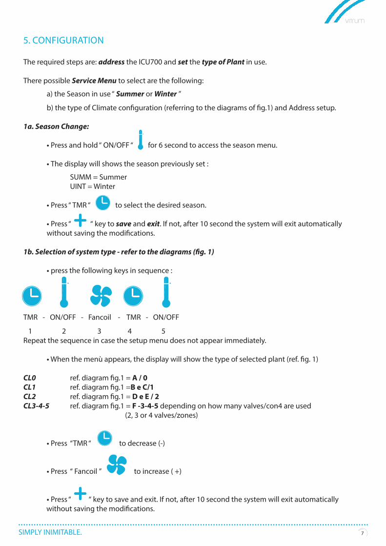
5. CONFIGURATION
The required steps are: address the ICU700 and set the type of Plant in use.
There possible Service Menu to select are the following:
a) the Season in use “ Summer or Winter ”
b) the type of Climate configuration (referring to the diagrams of fig.1) and Address setup.
1a. Season Change:
• Press and hold “ ON/OFF “ for 6 second to access the season menu.
• The display will shows the season previously set : SUMM = Summer UINT = Winter
• Press “ TMR “ to select the desired season.
• Press “ “ key to save and exit. If not, after 10 second the system will exit automatically without saving the modifications.
1b. Selection of system type - refer to the diagrams (fig. 1)
• press the following keys in sequence :
TMR - ON/OFF - Fancoil - TMR - ON/OFF
1 2 3 4 5Repeat the sequence in case the setup menu does not appear immediately.
• When the menù appears, the display will show the type of selected plant (ref. fig. 1)
CL0 ref. diagram fig.1 = A / 0CL1 ref. diagram fig.1 =B e C/1CL2 ref. diagram fig.1 = D e E / 2CL3-4-5 ref. diagram fig.1 = F -3-4-5 depending on how many valves/con4 are used (2, 3 or 4 valves/zones)
• Press “TMR “ to decrease (-)
• Press “ Fancoil ” to increase ( +)
• Press “ “ key to save and exit. If not, after 10 second the system will exit automatically without saving the modifications.
SIMPLY INIMITABLE. 8
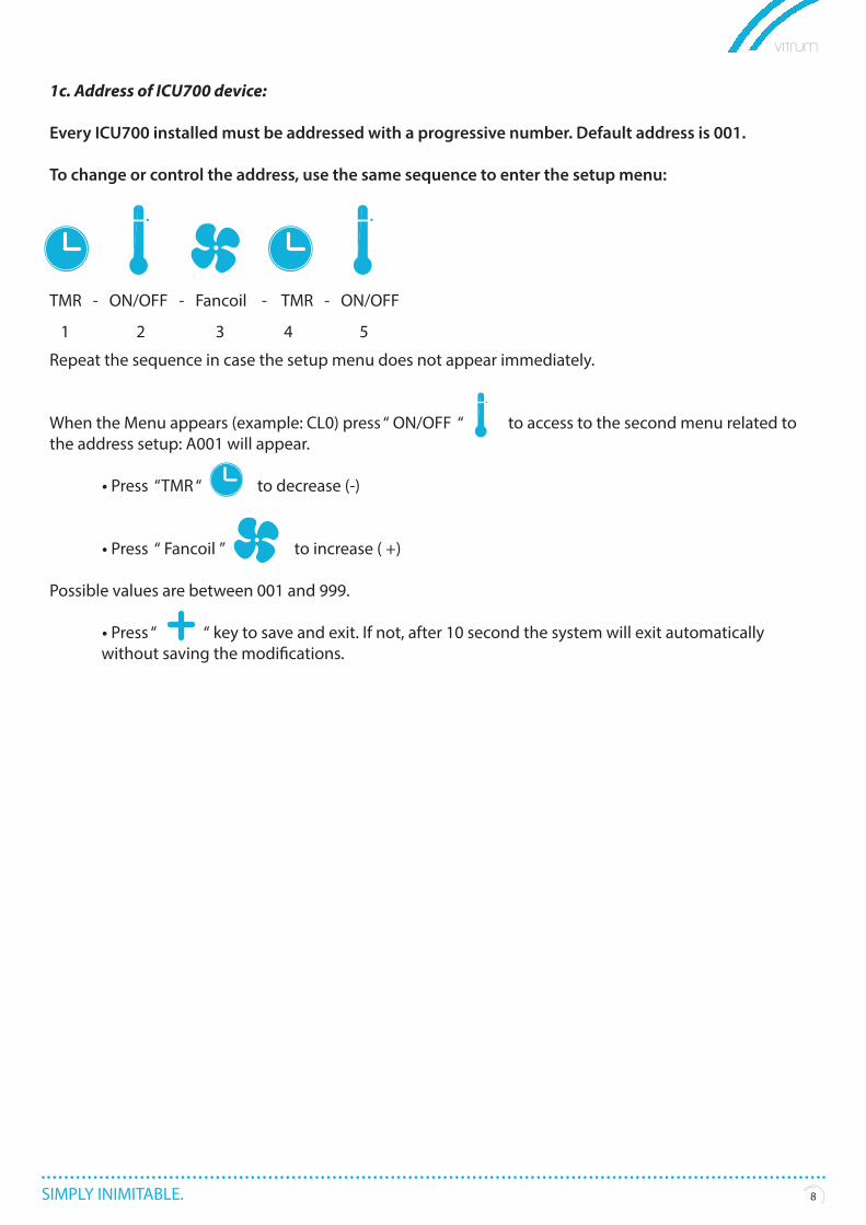
1c. Address of ICU700 device:
Every ICU700 installed must be addressed with a progressive number. Default address is 001.
To change or control the address, use the same sequence to enter the setup menu:
TMR - ON/OFF - Fancoil - TMR - ON/OFF
1 2 3 4 5
Repeat the sequence in case the setup menu does not appear immediately.
When the Menu appears (example: CL0) press “ ON/OFF “ to access to the second menu related to the address setup: A001 will appear.
• Press “TMR “ to decrease (-)
• Press “ Fancoil ” to increase ( +)
Possible values are between 001 and 999.
• Press “ “ key to save and exit. If not, after 10 second the system will exit automatically without saving the modifications.
SIMPLY INIMITABLE. 9
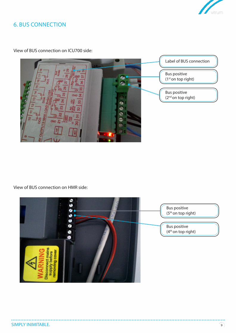
6. BUS CONNECTION
View of BUS connection on ICU700 side:
View of BUS connection on HMR side:
Label of BUS connection
Bus positive(1st on top right)
Bus positive(2nd on top right)
Bus positive(5th on top right)
Bus positive(4th on top right)
SIMPLY INIMITABLE. 1010
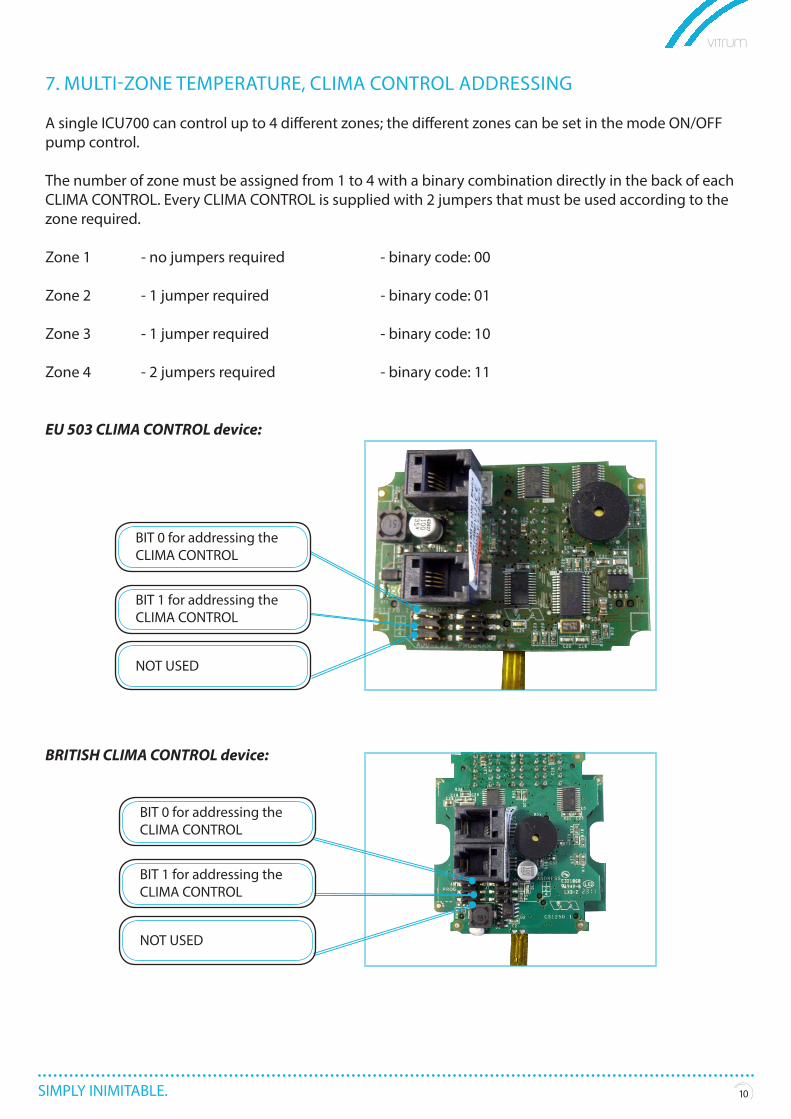
7. MULTI-ZONE TEMPERATURE, CLIMA CONTROL ADDRESSING
A single ICU700 can control up to 4 different zones; the different zones can be set in the mode ON/OFF pump control.
The number of zone must be assigned from 1 to 4 with a binary combination directly in the back of each CLIMA CONTROL. Every CLIMA CONTROL is supplied with 2 jumpers that must be used according to the zone required.
Zone 1 - no jumpers required - binary code: 00
Zone 2 - 1 jumper required - binary code: 01
Zone 3 - 1 jumper required - binary code: 10
Zone 4 - 2 jumpers required - binary code: 11
EU 503 CLIMA CONTROL device:
BRITISH CLIMA CONTROL device:
BIT 0 for addressing the CLIMA CONTROL
BIT 1 for addressing the CLIMA CONTROL
NOT USED
BIT 0 for addressing the CLIMA CONTROL
BIT 1 for addressing the CLIMA CONTROL
NOT USED
SIMPLY INIMITABLE. 1111
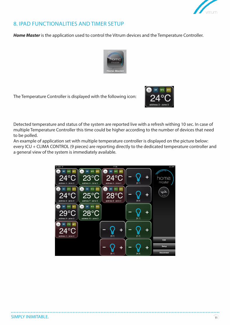
8. IPAD FUNCTIONALITIES AND TIMER SETUP
Home Master is the application used to control the Vitrum devices and the Temperature Controller.
The Temperature Controller is displayed with the following icon:
Detected temperature and status of the system are reported live with a refresh withing 10 sec. In case of multiple Temperature Controller this time could be higher according to the number of devices that need to be polled.An example of application set with multiple temperature controller is displayed on the picture below: every ICU + CLIMA CONTROL (9 pieces) are reporting directly to the dedicated temperature controller and a general view of the system is immediately available.
SIMPLY INIMITABLE. 1212
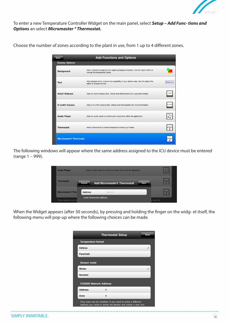
To enter a new Temperature Controller Widget on the main panel, select Setup – Add Func- tions and Options an select Micromaster ® Thermostat.
Choose the number of zones according to the plant in use, from 1 up to 4 different zones.
The following windows will appear where the same address assigned to the ICU device must be entered (range 1 – 999).
When the Widget appears (after 30 seconds), by pressing and holding the finger on the widg- et itself, the following menu will pop-up where the following choices can be made.
SIMPLY INIMITABLE. 13
Important: the Season mode will effect automatically also the ICU devices without need to manually set them through the CLIMA CONTROL.
Zone: it correspond to the different zones controller by the same ICU and different CLIMA CONTROL. Default is 1 in case of just 1 zone; other values can be 2 (2nd zone), 3 (3rd zone), 4 (4th zone). Zone set on the CLIMA CONTROL depends on the hardware bridge (jumpers) in the back of the device (see previous chapter).
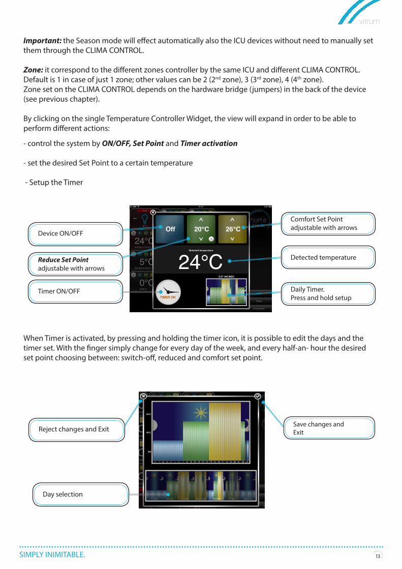
By clicking on the single Temperature Controller Widget, the view will expand in order to be able to perform different actions:
- control the system by ON/OFF, Set Point and Timer activation
- set the desired Set Point to a certain temperature
- Setup the Timer
When Timer is activated, by pressing and holding the timer icon, it is possible to edit the days and the timer set. With the finger simply change for every day of the week, and every half-an- hour the desired set point choosing between: switch-off, reduced and comfort set point.
13
Device ON/OFF
Reduce Set Pointadjustable with arrows
Timer ON/OFF
Reject changes and Exit
Day selection
Detected temperature
Comfort Set Pointadjustable with arrows
Daily Timer.Press and hold setup
Save changes and Exit

follow Vitrum
THINK SIMPLE S.r.l.
SEDE AMMINISTRATIVA E OPERATIVAViale Lino Zanussi, 333170 Pordenone ITT +39 0434 516216F +39 0434 516230
SEDE LEGALE E COMMERCIALECorso Garibaldi, 86
20121 Milano ITT +39 02 65560029F +39 02 45498295
vitrumsense.com