manual etx-205a
TRANSCRIPT
7/25/2019 Manual ETX-205A
http://slidepdf.com/reader/full/manual-etx-205a 1/409
ETX-205ACarrier Ethernet Demarcation Device
Version 4.01
IN STALLATI ONAND
OP E R AT I ONMAN UAL
The Access Company

7/25/2019 Manual ETX-205A
http://slidepdf.com/reader/full/manual-etx-205a 2/409

7/25/2019 Manual ETX-205A
http://slidepdf.com/reader/full/manual-etx-205a 3/409
ETX-205ACarrier Ethernet Demarcation Device
Version 4.01
Installation and Operation Manual
Notice
This manual contains information that is proprietary to RAD Data Communications Ltd. ("RAD").No part of this publication may be reproduced in any form whatsoever without prior writtenapproval by RAD Data Communications.
Right, title and interest, all information, copyrights, patents, know-how, trade secrets and other
intellectual property or other proprietary rights relating to this manual and to the ETX-205A andany software components contained therein are proprietary products of RAD protected underinternational copyright law and shall be and remain solely with RAD.
The ETX-205A product name is owned by RAD. No right, license, or interest to such trademark isgranted hereunder, and you agree that no such right, license, or interest shall be asserted byyou with respect to such trademark. The RAD name, logo, logotype, and the terms EtherAccess,TDMoIP and TDMoIP Driven, and the product names Optimux and IPmux, are registeredtrademarks of RAD Data Communications Ltd. All other trademarks are the property of theirrespective holders.
You shall not copy, reverse compile or reverse assemble all or any portion of the Manual or theETX-205A. You are prohibited from, and shall not, directly or indirectly, develop, market,distribute, license, or sell any product that supports substantially similar functionality as theETX-205A, based on or derived in any way from the ETX-205A. Your undertaking in thisparagraph shall survive the termination of this Agreement.
This Agreement is effective upon your opening of the ETX-205A package and shall continue untilterminated. RAD may terminate this Agreement upon the breach by you of any term hereof.Upon such termination by RAD, you agree to return to RAD the ETX-205A and all copies andportions thereof.
For further information contact RAD at the address below or contact your local distributor.
International Headquarters
RAD Data Communications Ltd.
24 Raoul Wallenberg StreetTel Aviv 69719, IsraelTel: 972-3-6458181Fax: 972-3-6498250, 6474436E-mail: [email protected]
North America Headquarters
RAD Data Communications Inc.
900 Corporate DriveMahwah, NJ 07430, USATel: (201) 5291100, Toll free: 1-800-4447234Fax: (201) 5295777E-mail: [email protected]
© 2011–2012 RAD Data Communications Ltd. Publication No. 527-200-09/12
7/25/2019 Manual ETX-205A
http://slidepdf.com/reader/full/manual-etx-205a 4/409
Front Matter Installation and Operation Manual
ii ETX-205A Ver. 4.01
Limited Warranty
RAD warrants to DISTRIBUTOR that the hardware in the ETX-205A to be delivered hereunder shallbe free of defects in material and workmanship under normal use and service for a period oftwelve (12) months following the date of shipment to DISTRIBUTOR.
If, during the warranty period, any component part of the equipment becomes defective byreason of material or workmanship, and DISTRIBUTOR immediately notifies RAD of such defect,RAD shall have the option to choose the appropriate corrective action: a) supply a replacementpart, or b) request return of equipment to its plant for repair, or c) perform necessary repair atthe equipment's location. In the event that RAD requests the return of equipment, each partyshall pay one-way shipping costs.
RAD shall be released from all obligations under its warranty in the event that the equipment hasbeen subjected to misuse, neglect, accident or improper installation, or if repairs ormodifications were made by persons other than RAD's own authorized service personnel, unlesssuch repairs by others were made with the written consent of RAD.
The above warranty is in lieu of all other warranties, expressed or implied. There are nowarranties which extend beyond the face hereof, including, but not limited to, warranties of
merchantability and fitness for a particular purpose, and in no event shall RAD be liable forconsequential damages.
RAD shall not be liable to any person for any special or indirect damages, including, but notlimited to, lost profits from any cause whatsoever arising from or in any way connected with themanufacture, sale, handling, repair, maintenance or use of the ETX-205A, and in no event shallRAD's liability exceed the purchase price of the ETX-205A.
DISTRIBUTOR shall be responsible to its customers for any and all warranties which it makesrelating to ETX-205A and for ensuring that replacements and other adjustments required inconnection with the said warranties are satisfactory.
Software components in the ETX-205A are provided "as is" and without warranty of any kind.RAD disclaims all warranties including the implied warranties of merchantability and fitness for aparticular purpose. RAD shall not be liable for any loss of use, interruption of business orindirect, special, incidental or consequential damages of any kind. In spite of the above RADshall do its best to provide error-free software products and shall offer free Software updatesduring the warranty period under this Agreement.
RAD's cumulative liability to you or any other party for any loss or damages resulting from anyclaims, demands, or actions arising out of or relating to this Agreement and the ETX-205A shallnot exceed the sum paid to RAD for the purchase of the ETX-205A. In no event shall RAD beliable for any indirect, incidental, consequential, special, or exemplary damages or lost profits,even if RAD has been advised of the possibility of such damages.
This Agreement shall be construed and governed in accordance with the laws of the State ofIsrael.
Product Disposal
To facilitate the reuse, recycling and other forms of recovery of wasteequipment in protecting the environment, the owner of this RAD product isrequired to refrain from disposing of this product as unsorted municipal wasteat the end of its life cycle. Upon termination of the unit’s use, customers shouldprovide for its collection for reuse, recycling or other form of environmentallyconscientious disposal.

7/25/2019 Manual ETX-205A
http://slidepdf.com/reader/full/manual-etx-205a 5/409
Installation and Operation Manual Front Matter
ETX-205A Ver. 4.01 iii
General Safety Instructions
The following instructions serve as a general guide for the safe installation and operation oftelecommunications products. Additional instructions, if applicable, are included inside themanual.
Safety Symbols
This symbol may appear on the equipment or in the text. It indicates
potential safety hazards regarding product operation or maintenance to
operator or service personnel.
Danger of electric shock Avoid any contact with the marked surface while
the product is energized or connected to outdoor telecommunication lines.
Protective ground: the marked lug or terminal should be connected to thebuilding protective ground bus.
Some products may be equipped with a laser diode. In such cases, a label
with the laser class and other warnings as applicable will be attached near
the optical transmitter. The laser warning symbol may be also attached.
Please observe the following precautions:
•
Before turning on the equipment, make sure that the fiber optic cable is
intact and is connected to the transmitter.
• Do not attempt to adjust the laser drive current.
• Do not use broken or unterminated fiber-optic cables/connectors or look
straight at the laser beam.
•
The use of optical devices with the equipment will increase eye hazard.
•
Use of controls, adjustments or performing procedures other than those
specified herein, may result in hazardous radiation exposure.
ATTENTION: The laser beam may be invisible
In some cases, the users may insert their own SFP laser transceivers into the product. Users arealerted that RAD cannot be held responsible for any damage that may result if non-compliant
transceivers are used. In particular, users are warned to use only agency approved products thatcomply with the local laser safety regulations for Class 1 laser products.
Always observe standard safety precautions during installation, operation and maintenance ofthis product. Only qualified and authorized service personnel should carry out adjustment,maintenance or repairs to this product. No installation, adjustment, maintenance or repairsshould be performed by either the operator or the user.
Warning
Warning
7/25/2019 Manual ETX-205A
http://slidepdf.com/reader/full/manual-etx-205a 6/409
Front Matter Installation and Operation Manual
iv ETX-205A Ver. 4.01
Handling Energized Products
General Safety Practices
Do not touch or tamper with the power supply when the power cord is connected. Line voltagesmay be present inside certain products even when the power switch (if installed) is in the OFFposition or a fuse is blown. For DC-powered products, although the voltages levels are usuallynot hazardous, energy hazards may still exist.
Before working on equipment connected to power lines or telecommunication lines, remove jewelry or any other metallic object that may come into contact with energized parts.
Unless otherwise specified, all products are intended to be grounded during normal use.Grounding is provided by connecting the mains plug to a wall socket with a protective groundterminal. If a ground lug is provided on the product, it should be connected to the protectiveground at all times, by a wire with a diameter of 18 AWG or wider. Rack-mounted equipmentshould be mounted only in grounded racks and cabinets.
Always make the ground connection first and disconnect it last. Do not connect
telecommunication cables to ungrounded equipment. Make sure that all other cables aredisconnected before disconnecting the ground.
Some products may have panels secured by thumbscrews with a slotted head. These panels maycover hazardous circuits or parts, such as power supplies. These thumbscrews should thereforealways be tightened securely with a screwdriver after both initial installation and subsequentaccess to the panels.
The ETX-205A may be equipped with surge protectors between the AC
mains and ground. The connection to the protective ground must be
maintained whenever the unit is connected to AC mains.
In Finland, Norway and Sweden, the unit is restricted to installation by service personnel inRestricted Access Locations only.
FI Laite on liitettävä suojamaadoituskoskettimilla varustettuun pistorasiaan
NO Apparatet må tilkoples jordet stikkontakt
SE Apparaten skall anslutas till jordat uttag
Connecting AC Mains
Make sure that the electrical installation complies with local codes.
Always connect the AC plug to a wall socket with a protective ground.
The maximum permissible current capability of the branch distribution circuit that supplies power
to the product is 16A (20A for USA and Canada). The circuit breaker in the building installationshould have high breaking capacity and must operate at short-circuit current exceeding 35A (40Afor USA and Canada).
Always connect the power cord first to the equipment and then to the wall socket. If a powerswitch is provided in the equipment, set it to the OFF position. If the power cord cannot bereadily disconnected in case of emergency, make sure that a readily accessible circuit breaker oremergency switch is installed in the building installation.
In cases when the power distribution system is IT type, the switch must disconnect both polessimultaneously.
Warning
7/25/2019 Manual ETX-205A
http://slidepdf.com/reader/full/manual-etx-205a 7/409
Installation and Operation Manual Front Matter
ETX-205A Ver. 4.01 v
Connecting DC Power
Unless otherwise specified in the manual, the DC input to the equipment is floating in referenceto the ground. Any single pole can be externally grounded.
Due to the high current capability of DC power systems, care should be taken when connectingthe DC supply to avoid short-circuits and fire hazards.
Make sure that the DC power supply is electrically isolated from any AC source and that theinstallation complies with the local codes.
The maximum permissible current capability of the branch distribution circuit that supplies powerto the product is 16A (20A for USA and Canada). The circuit breaker in the building installationshould have high breaking capacity and must operate at short-circuit current exceeding 35A (40Afor USA and Canada).
Before connecting the DC supply wires, ensure that power is removed from the DC circuit. Locatethe circuit breaker of the panel board that services the equipment and switch it to the OFFposition. When connecting the DC supply wires, first connect the ground wire to thecorresponding terminal, then the positive pole and last the negative pole. Switch the circuitbreaker back to the ON position.
A readily accessible disconnect device that is suitably rated and approved should be incorporatedin the building installation.
If the DC power supply is floating, the switch must disconnect both poles simultaneously.
Connecting Data and Telecommunications Cables
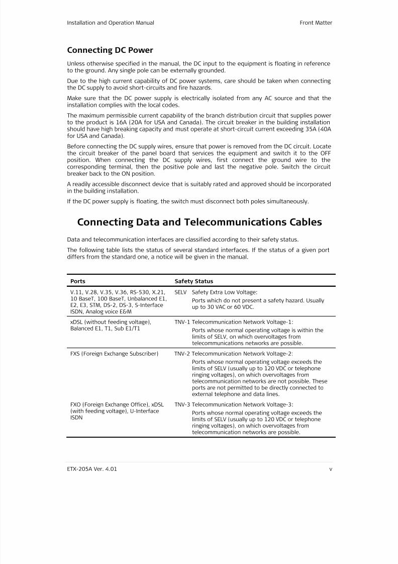
Data and telecommunication interfaces are classified according to their safety status.
The following table lists the status of several standard interfaces. If the status of a given portdiffers from the standard one, a notice will be given in the manual.
Ports Safety Status
V.11, V.28, V.35, V.36, RS-530, X.21,10 BaseT, 100 BaseT, Unbalanced E1,E2, E3, STM, DS-2, DS-3, S-InterfaceISDN, Analog voice E&M
SELV Safety Extra Low Voltage:
Ports which do not present a safety hazard. Usuallyup to 30 VAC or 60 VDC.
xDSL (without feeding voltage),Balanced E1, T1, Sub E1/T1
TNV-1 Telecommunication Network Voltage-1:
Ports whose normal operating voltage is within thelimits of SELV, on which overvoltages from
telecommunications networks are possible.
FXS (Foreign Exchange Subscriber) TNV-2 Telecommunication Network Voltage-2:
Ports whose normal operating voltage exceeds thelimits of SELV (usually up to 120 VDC or telephone
ringing voltages), on which overvoltages fromtelecommunication networks are not possible. Theseports are not permitted to be directly connected toexternal telephone and data lines.
FXO (Foreign Exchange Office), xDSL(with feeding voltage), U-InterfaceISDN
TNV-3 Telecommunication Network Voltage-3:
Ports whose normal operating voltage exceeds thelimits of SELV (usually up to 120 VDC or telephoneringing voltages), on which overvoltages fromtelecommunication networks are possible.

7/25/2019 Manual ETX-205A
http://slidepdf.com/reader/full/manual-etx-205a 8/409
Front Matter Installation and Operation Manual
vi ETX-205A Ver. 4.01
Always connect a given port to a port of the same safety status. If in doubt, seek the assistance
of a qualified safety engineer.
Always make sure that the equipment is grounded before connecting telecommunication cables.Do not disconnect the ground connection before disconnecting all telecommunications cables.
Some SELV and non-SELV circuits use the same connectors. Use caution when connecting cables.Extra caution should be exercised during thunderstorms.
When using shielded or coaxial cables, verify that there is a good ground connection at bothends. The grounding and bonding of the ground connections should comply with the local codes.
The telecommunication wiring in the building may be damaged or present a fire hazard in case ofcontact between exposed external wires and the AC power lines. In order to reduce the risk,there are restrictions on the diameter of wires in the telecom cables, between the equipmentand the mating connectors.
To reduce the risk of fire, use only No. 26 AWG or larger telecommunicationline cords.
Pour réduire les risques s’incendie, utiliser seulement des conducteurs detélécommunications 26 AWG ou de section supérieure.
Some ports are suitable for connection to intra-building or non-exposed wiring or cabling only. Insuch cases, a notice will be given in the installation instructions.
Do not attempt to tamper with any carrier-provided equipment or connection hardware.
Electromagnetic Compatibility (EMC)
The equipment is designed and approved to comply with the electromagnetic regulations of
major regulatory bodies. The following instructions may enhance the performance of theequipment and will provide better protection against excessive emission and better immunityagainst disturbances.
A good ground connection is essential. When installing the equipment in a rack, make sure toremove all traces of paint from the mounting points. Use suitable lock-washers and torque. If anexternal grounding lug is provided, connect it to the ground bus using braided wire as short aspossible.
The equipment is designed to comply with EMC requirements when connecting it with unshieldedtwisted pair (UTP) cables. However, the use of shielded wires is always recommended, especiallyfor high-rate data. In some cases, when unshielded wires are used, ferrite cores should beinstalled on certain cables. In such cases, special instructions are provided in the manual.
Disconnect all wires which are not in permanent use, such as cables used for one-time
configuration.
The compliance of the equipment with the regulations for conducted emission on the data linesis dependent on the cable quality. The emission is tested for UTP with 80 dB longitudinalconversion loss (LCL).
Unless otherwise specified or described in the manual, TNV-1 and TNV-3 ports provide secondaryprotection against surges on the data lines. Primary protectors should be provided in the buildinginstallation.
Caution
Attention

7/25/2019 Manual ETX-205A
http://slidepdf.com/reader/full/manual-etx-205a 9/409
Installation and Operation Manual Front Matter
ETX-205A Ver. 4.01 vii
The equipment is designed to provide adequate protection against electro-static discharge (ESD).However, it is good working practice to use caution when connecting cables terminated withplastic connectors (without a grounded metal hood, such as flat cables) to sensitive data lines.Before connecting such cables, discharge yourself by touching ground or wear an ESD preventivewrist strap.
FCC-15 User Information
This equipment has been tested and found to comply with the limits of the Class B digital device,pursuant to Part 15 of the FCC rules. These limits are designed to provide reasonable protectionagainst harmful interference when the equipment is operated in a commercial environment. Thisequipment generates, uses and can radiate radio frequency energy and, if not installed and usedin accordance with the Installation and Operation manual, may cause harmful interference to theradio communications. Operation of this equipment in a residential area is likely to cause harmfulinterference in which case the user will be required to correct the interference at his ownexpense.
Canadian Emission Requirements
This Class B digital apparatus meets all the requirements of the Canadian Interference-CausingEquipment Regulation.
Cet appareil numérique de la classe B respecte toutes les exigences du Règlement sur le matérielbrouilleur du Canada.
7/25/2019 Manual ETX-205A
http://slidepdf.com/reader/full/manual-etx-205a 10/409
Front Matter Installation and Operation Manual
viii ETX-205A Ver. 4.01
F
i
Mise au rebut du produit
Afin de faciliter la réutilisation, le recyclage ainsi que d'autres formes derécupération d'équipement mis au rebut dans le cadre de la protection del'environnement, il est demandé au propriétaire de ce produit RAD de ne pas
mettre ce dernier au rebut en tant que déchet municipal non trié, une fois que leproduit est arrivé en fin de cycle de vie. Le client devrait proposer des solutionsde réutilisation, de recyclage ou toute autre forme de mise au rebut de cetteunité dans un esprit de protection de l'environnement, lorsqu'il aura fini del'utiliser.
Instructions générales de sécurité
Les instructions suivantes servent de guide général d'installation et d'opération sécurisées desproduits de télécommunications. Des instructions supplémentaires sont éventuellementindiquées dans le manuel.
Symboles de sécurité
Ce symbole peut apparaitre sur l'équipement ou dans le texte. Il indique des
risques potentiels de sécurité pour l'opérateur ou le personnel de service,
quant à l'opération du produit ou à sa maintenance.
Danger de choc électrique Evitez tout contact avec la surface marquée
tant que le produit est sous tension ou connecté à des lignes externes de
télécommunications.
Mise à la terre de protection : la cosse ou la borne marquée devrait êtreconnectée à la prise de terre de protection du bâtiment.
Avertissement
7/25/2019 Manual ETX-205A
http://slidepdf.com/reader/full/manual-etx-205a 11/409
Installation and Operation Manual Front Matter
ETX-205A Ver. 4.01 ix
Certains produits peuvent être équipés d'une diode laser. Dans de tels cas,
une étiquette indiquant la classe laser ainsi que d'autres avertissements, le
cas échéant, sera jointe près du transmetteur optique. Le symbole
d'avertissement laser peut aussi être joint.
Veuillez observer les précautions suivantes :
•
Avant la mise en marche de l'équipement, assurez-vous que le câble de
fibre optique est intact et qu'il est connecté au transmetteur.
• Ne tentez pas d'ajuster le courant de la commande laser.
• N'utilisez pas des câbles ou connecteurs de fibre optique cassés ou sans
terminaison et n'observez pas directement un rayon laser.
• L'usage de périphériques optiques avec l'équipement augmentera le
risque pour les yeux.
• L'usage de contrôles, ajustages ou procédures autres que celles
spécifiées ici pourrait résulter en une dangereuse exposition aux
radiations.
ATTENTION : Le rayon laser peut être invisible
Les utilisateurs pourront, dans certains cas, insérer leurs propres émetteurs-récepteurs Laser SFPdans le produit. Les utilisateurs sont avertis que RAD ne pourra pas être tenue responsable detout dommage pouvant résulter de l'utilisation d'émetteurs-récepteurs non conformes. Plusparticulièrement, les utilisateurs sont avertis de n'utiliser que des produits approuvés parl'agence et conformes à la réglementation locale de sécurité laser pour les produits laser declasse 1.
Respectez toujours les précautions standards de sécurité durant l'installation, l'opération et lamaintenance de ce produit. Seul le personnel de service qualifié et autorisé devrait effectuerl'ajustage, la maintenance ou les réparations de ce produit. Aucune opération d'installation,d'ajustage, de maintenance ou de réparation ne devrait être effectuée par l'opérateur oul'utilisateur.
Manipuler des produits sous tension
Règles générales de sécurité
Ne pas toucher ou altérer l'alimentation en courant lorsque le câble d'alimentation est branché.Des tensions de lignes peuvent être présentes dans certains produits, même lorsque lecommutateur (s'il est installé) est en position OFF ou si le fusible est rompu. Pour les produitsalimentés par CC, les niveaux de tension ne sont généralement pas dangereux mais des risquesde courant peuvent toujours exister.
Avant de travailler sur un équipement connecté aux lignes de tension ou de télécommunications,retirez vos bijoux ou tout autre objet métallique pouvant venir en contact avec les pièces soustension.
Sauf s'il en est autrement indiqué, tous les produits sont destinés à être mis à la terre durantl'usage normal. La mise à la terre est fournie par la connexion de la fiche principale à une prisemurale équipée d'une borne protectrice de mise à la terre. Si une cosse de mise à la terre estfournie avec le produit, elle devrait être connectée à tout moment à une mise à la terre deprotection par un conducteur de diamètre 18 AWG ou plus. L'équipement monté en châssis nedevrait être monté que sur des châssis et dans des armoires mises à la terre.
Branchez toujours la mise à la terre en premier et débranchez-la en dernier. Ne branchez pas descâbles de télécommunications à un équipement qui n'est pas mis à la terre. Assurez-vous quetous les autres câbles sont débranchés avant de déconnecter la mise à la terre.
Avertissement
7/25/2019 Manual ETX-205A
http://slidepdf.com/reader/full/manual-etx-205a 12/409
Front Matter Installation and Operation Manual
x ETX-205A Ver. 4.01
F
i
Connexion au courant du secteur
Assurez-vous que l'installation électrique est conforme à la réglementation locale.
Branchez toujours la fiche de secteur à une prise murale équipée d'une borne protectrice de miseà la terre.
La capacité maximale permissible en courant du circuit de distribution de la connexion alimentantle produit est de 16A (20A aux Etats-Unis et Canada). Le coupe-circuit dans l'installation dubâtiment devrait avoir une capacité élevée de rupture et devrait fonctionner sur courant decourt-circuit dépassant 35A (40A aux Etats-Unis et Canada).
Branchez toujours le câble d'alimentation en premier à l'équipement puis à la prise murale. Si uncommutateur est fourni avec l'équipement, fixez-le en position OFF. Si le câble d'alimentation nepeut pas être facilement débranché en cas d'urgence, assurez-vous qu'un coupe-circuit ou undisjoncteur d'urgence facilement accessible est installé dans l'installation du bâtiment.
Le disjoncteur devrait déconnecter simultanément les deux pôles si le système de distribution decourant est de type IT.
Connexion d'alimentation CC
Sauf s'il en est autrement spécifié dans le manuel, l'entrée CC de l'équipement est flottante parrapport à la mise à la terre. Tout pôle doit être mis à la terre en externe.
A cause de la capacité de courant des systèmes à alimentation CC, des précautions devraientêtre prises lors de la connexion de l'alimentation CC pour éviter des courts-circuits et des risquesd'incendie.
Assurez-vous que l'alimentation CC est isolée de toute source de courant CA (secteur) et quel'installation est conforme à la réglementation locale.
La capacité maximale permissible en courant du circuit de distribution de la connexion alimentantle produit est de 16A (20A aux Etats-Unis et Canada). Le coupe-circuit dans l'installation dubâtiment devrait avoir une capacité élevée de rupture et devrait fonctionner sur courant decourt-circuit dépassant 35A (40A aux Etats-Unis et Canada).
Avant la connexion des câbles d'alimentation en courant CC, assurez-vous que le circuit CC n'estpas sous tension. Localisez le coupe-circuit dans le tableau desservant l'équipement et fixez-leen position OFF. Lors de la connexion de câbles d'alimentation CC, connectez d'abord leconducteur de mise à la terre à la borne correspondante, puis le pôle positif et en dernier, lepôle négatif. Remettez le coupe-circuit en position ON.
Un disjoncteur facilement accessible, adapté et approuvé devrait être intégré à l'installation dubâtiment.
Le disjoncteur devrait déconnecter simultanément les deux pôles si l'alimentation en courant CCest flottante.

7/25/2019 Manual ETX-205A
http://slidepdf.com/reader/full/manual-etx-205a 13/409
Installation and Operation Manual Front Matter
ETX-205A Ver. 4.01 xi
7/25/2019 Manual ETX-205A
http://slidepdf.com/reader/full/manual-etx-205a 14/409
Front Matter Installation and Operation Manual
xii ETX-205A Ver. 4.01
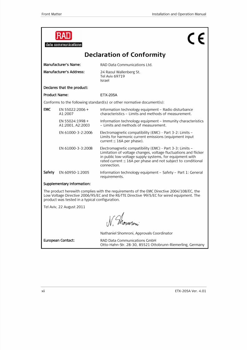
Declaration of Conformity
Manufacturer's Name: RAD Data Communications Ltd.
Manufacturer's Address: 24 Raoul Wallenberg St.Tel Aviv 69719Israel
Declares that the product:
Product Name: ETX-205A
Conforms to the following standard(s) or other normative document(s):
EMC EN 55022:2006 +A1:2007
Information technology equipment – Radio disturbancecharacteristics – Limits and methods of measurement.
EN 55024:1998 +A1:2001, A2:2003
Information technology equipment – Immunity characteristics– Limits and methods of measurement.
EN 61000-3-2:2006 Electromagnetic compatibility (EMC) - Part 3-2: Limits –Limits for harmonic current emissions (equipment inputcurrent ≤ 16A per phase).
EN 61000-3-3:2008 Electromagnetic compatibility (EMC) - Part 3-3: Limits –Limitation of voltage changes, voltage fluctuations and flickerin public low-voltage supply systems, for equipment withrated current ≤ 16A per phase and not subject to conditionalconnection.
Safety EN 60950-1:2005 Information technology equipment – Safety – Part 1: Generalrequirements.
Supplementary Information:
The product herewith complies with the requirements of the EMC Directive 2004/108/EC, theLow Voltage Directive 2006/95/EC and the R&TTE Directive 99/5/EC for wired equipment. Theproduct was tested in a typical configuration.
Tel Aviv, 22 August 2011
Nathaniel Shomroni, Approvals Coordinator
European Contact:
RAD Data Communications GmbHOtto-Hahn-Str. 28-30, 85521 Ottobrunn-Riemerling, Germany
7/25/2019 Manual ETX-205A
http://slidepdf.com/reader/full/manual-etx-205a 15/409
ETX-205A Ver. 4.01 xiii
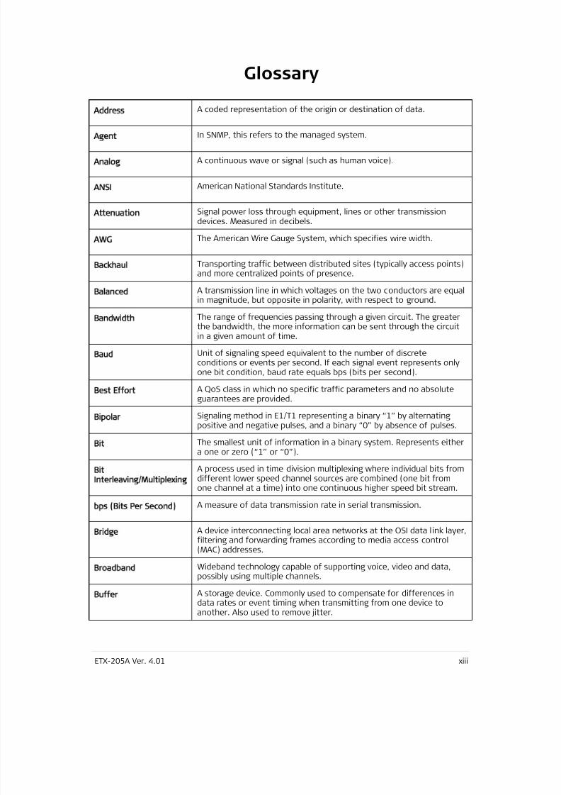
Glossary
Address
A coded representation of the origin or destination of data.
Agent
In SNMP, this refers to the managed system.
Analog
A continuous wave or signal (such as human voice).
ANSI
American National Standards Institute.
Attenuation
Signal power loss through equipment, lines or other transmissiondevices. Measured in decibels.
AWG
The American Wire Gauge System, which specifies wire width.
Backhaul Transporting traffic between distributed sites (typically access points)and more centralized points of presence.
Balanced
A transmission line in which voltages on the two conductors are equalin magnitude, but opposite in polarity, with respect to ground.
Bandwidth
The range of frequencies passing through a given circuit. The greaterthe bandwidth, the more information can be sent through the circuitin a given amount of time.
Baud
Unit of signaling speed equivalent to the number of discreteconditions or events per second. If each signal event represents onlyone bit condition, baud rate equals bps (bits per second).
Best Effort
A QoS class in which no specific traffic parameters and no absolute
guarantees are provided.
Bipolar
Signaling method in E1/T1 representing a binary “1” by alternatingpositive and negative pulses, and a binary “0” by absence of pulses.
Bit
The smallest unit of information in a binary system. Represents eithera one or zero (“1” or “0”).
Bit
Interleaving/Multiplexing
A process used in time division multiplexing where individual bits fromdifferent lower speed channel sources are combined (one bit fromone channel at a time) into one continuous higher speed bit stream.
bps (Bits Per Second)
A measure of data transmission rate in serial transmission.
Bridge A device interconnecting local area networks at the OSI data link layer,filtering and forwarding frames according to media access control(MAC) addresses.
Broadband
Wideband technology capable of supporting voice, video and data,possibly using multiple channels.
Buffer
A storage device. Commonly used to compensate for differences indata rates or event timing when transmitting from one device toanother. Also used to remove jitter.
7/25/2019 Manual ETX-205A
http://slidepdf.com/reader/full/manual-etx-205a 16/409
7/25/2019 Manual ETX-205A
http://slidepdf.com/reader/full/manual-etx-205a 17/409
Installation and Operation Manual Front Matter
ETX-205A Ver. 4.01 xv
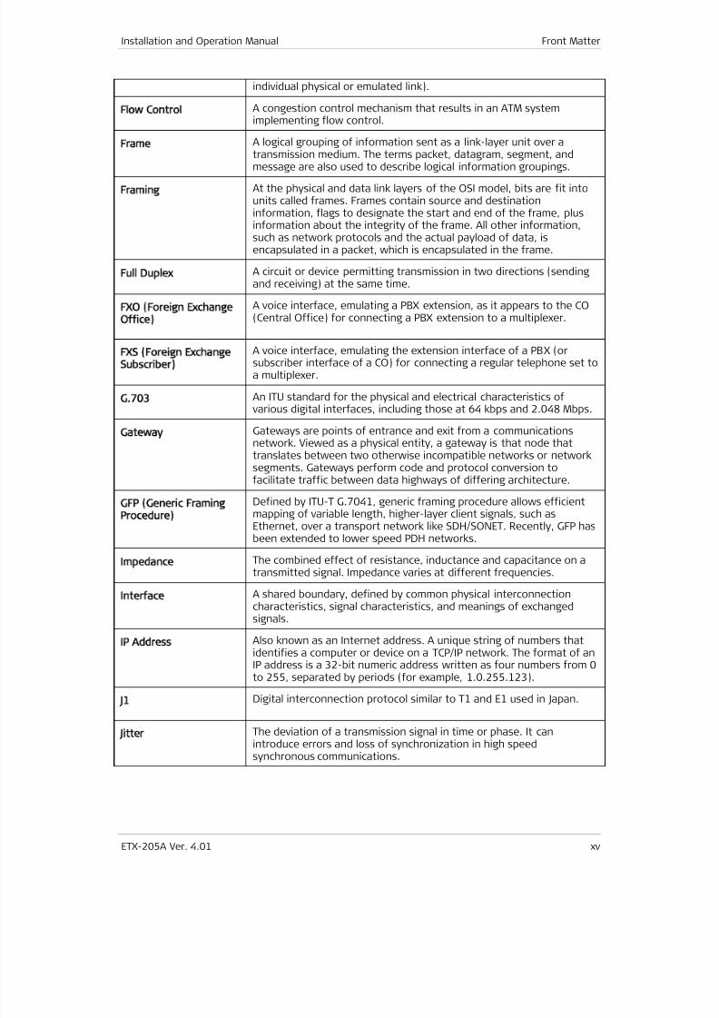
individual physical or emulated link).
Flow Control
A congestion control mechanism that results in an ATM systemimplementing flow control.
Frame
A logical grouping of information sent as a link-layer unit over atransmission medium. The terms packet, datagram, segment, and
message are also used to describe logical information groupings.
Framing
At the physical and data link layers of the OSI model, bits are fit intounits called frames. Frames contain source and destinationinformation, flags to designate the start and end of the frame, plusinformation about the integrity of the frame. All other information,such as network protocols and the actual payload of data, isencapsulated in a packet, which is encapsulated in the frame.
Full Duplex
A circuit or device permitting transmission in two directions (sendingand receiving) at the same time.
FXO (Foreign Exchange
Office)
A voice interface, emulating a PBX extension, as it appears to the CO(Central Office) for connecting a PBX extension to a multiplexer.
FXS (Foreign Exchange
Subscriber)
A voice interface, emulating the extension interface of a PBX (orsubscriber interface of a CO) for connecting a regular telephone set toa multiplexer.
G.703
An ITU standard for the physical and electrical characteristics ofvarious digital interfaces, including those at 64 kbps and 2.048 Mbps.
Gateway
Gateways are points of entrance and exit from a communicationsnetwork. Viewed as a physical entity, a gateway is that node thattranslates between two otherwise incompatible networks or networksegments. Gateways perform code and protocol conversion tofacilitate traffic between data highways of differing architecture.
GFP (Generic Framing
Procedure)
Defined by ITU-T G.7041, generic framing procedure allows efficientmapping of variable length, higher-layer client signals, such asEthernet, over a transport network like SDH/SONET. Recently, GFP hasbeen extended to lower speed PDH networks.
Impedance
The combined effect of resistance, inductance and capacitance on atransmitted signal. Impedance varies at different frequencies.
Interface
A shared boundary, defined by common physical interconnectioncharacteristics, signal characteristics, and meanings of exchangedsignals.
IP Address
Also known as an Internet address. A unique string of numbers thatidentifies a computer or device on a TCP/IP network. The format of anIP address is a 32-bit numeric address written as four numbers from 0
to 255, separated by periods (for example, 1.0.255.123).
J1
Digital interconnection protocol similar to T1 and E1 used in Japan.
Jitter
The deviation of a transmission signal in time or phase. It canintroduce errors and loss of synchronization in high speedsynchronous communications.
7/25/2019 Manual ETX-205A
http://slidepdf.com/reader/full/manual-etx-205a 18/409
Front Matter Installation and Operation Manual
xvi ETX-205A Ver. 4.01
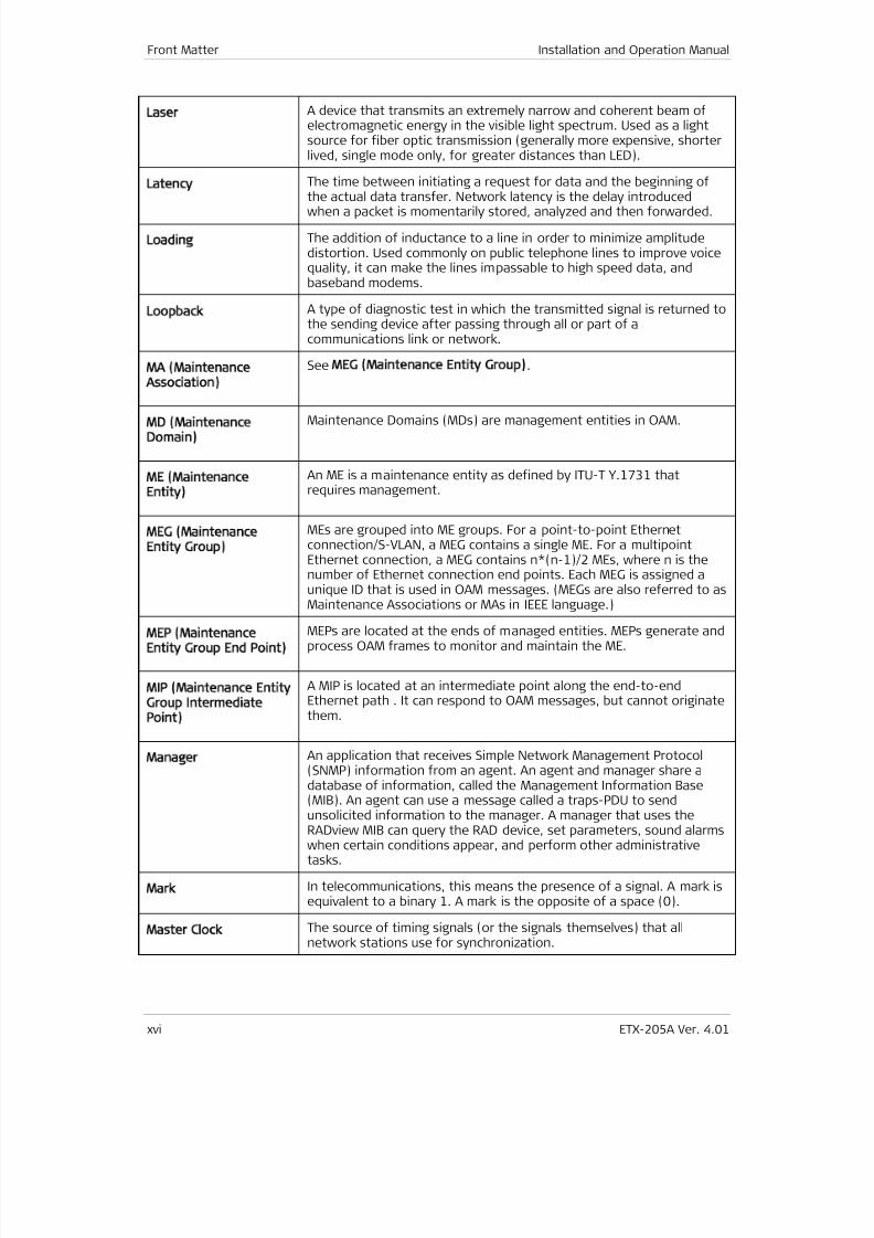
Laser
A device that transmits an extremely narrow and coherent beam ofelectromagnetic energy in the visible light spectrum. Used as a lightsource for fiber optic transmission (generally more expensive, shorterlived, single mode only, for greater distances than LED).
Latency
The time between initiating a request for data and the beginning ofthe actual data transfer. Network latency is the delay introducedwhen a packet is momentarily stored, analyzed and then forwarded.
Loading
The addition of inductance to a line in order to minimize amplitudedistortion. Used commonly on public telephone lines to improve voicequality, it can make the lines impassable to high speed data, andbaseband modems.
Loopback
A type of diagnostic test in which the transmitted signal is returned tothe sending device after passing through all or part of acommunications link or network.
MA (Maintenance
Association)
See MEG (Maintenance Entity Group).
MD (Maintenance
Domain)
Maintenance Domains (MDs) are management entities in OAM.
ME (Maintenance
Entity)
An ME is a maintenance entity as defined by ITU-T Y.1731 thatrequires management.
MEG (Maintenance
Entity Group)
MEs are grouped into ME groups. For a point-to-point Ethernetconnection/S-VLAN, a MEG contains a single ME. For a multipointEthernet connection, a MEG contains n*(n-1)/2 MEs, where n is thenumber of Ethernet connection end points. Each MEG is assigned aunique ID that is used in OAM messages. (MEGs are also referred to asMaintenance Associations or MAs in IEEE language.)
MEP (Maintenance
Entity Group End Point)
MEPs are located at the ends of managed entities. MEPs generate andprocess OAM frames to monitor and maintain the ME.
MIP (Maintenance Entity
Group Intermediate
Point)
A MIP is located at an intermediate point along the end-to-endEthernet path . It can respond to OAM messages, but cannot originatethem.
Manager
An application that receives Simple Network Management Protocol(SNMP) information from an agent. An agent and manager share adatabase of information, called the Management Information Base(MIB). An agent can use a message called a traps-PDU to sendunsolicited information to the manager. A manager that uses theRADview MIB can query the RAD device, set parameters, sound alarmswhen certain conditions appear, and perform other administrativetasks.
Mark
In telecommunications, this means the presence of a signal. A mark isequivalent to a binary 1. A mark is the opposite of a space (0).
Master Clock
The source of timing signals (or the signals themselves) that allnetwork stations use for synchronization.
7/25/2019 Manual ETX-205A
http://slidepdf.com/reader/full/manual-etx-205a 19/409
Installation and Operation Manual Front Matter
ETX-205A Ver. 4.01 xvii
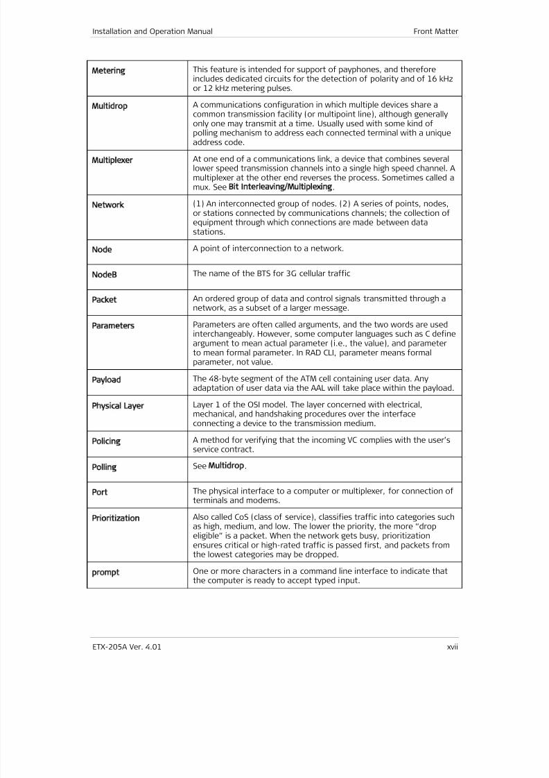
Metering
This feature is intended for support of payphones, and thereforeincludes dedicated circuits for the detection of polarity and of 16 kHzor 12 kHz metering pulses.
Multidrop
A communications configuration in which multiple devices share acommon transmission facility (or multipoint line), although generallyonly one may transmit at a time. Usually used with some kind ofpolling mechanism to address each connected terminal with a uniqueaddress code.
Multiplexer
At one end of a communications link, a device that combines severallower speed transmission channels into a single high speed channel. Amultiplexer at the other end reverses the process. Sometimes called amux. See Bit Interleaving/Multiplexing.
Network
(1) An interconnected group of nodes. (2) A series of points, nodes,or stations connected by communications channels; the collection ofequipment through which connections are made between datastations.
Node
A point of interconnection to a network.
NodeB
The name of the BTS for 3G cellular traffic
Packet
An ordered group of data and control signals transmitted through anetwork, as a subset of a larger message.
Parameters
Parameters are often called arguments, and the two words are usedinterchangeably. However, some computer languages such as C defineargument to mean actual parameter (i.e., the value), and parameterto mean formal parameter. In RAD CLI, parameter means formalparameter, not value.
Payload
The 48-byte segment of the ATM cell containing user data. Any
adaptation of user data via the AAL will take place within the payload.
Physical Layer
Layer 1 of the OSI model. The layer concerned with electrical,mechanical, and handshaking procedures over the interfaceconnecting a device to the transmission medium.
Policing
A method for verifying that the incoming VC complies with the user’sservice contract.
Polling
See Multidrop.
Port
The physical interface to a computer or multiplexer, for connection ofterminals and modems.
Prioritization Also called CoS (class of service), classifies traffic into categories suchas high, medium, and low. The lower the priority, the more “dropeligible” is a packet. When the network gets busy, prioritizationensures critical or high-rated traffic is passed first, and packets fromthe lowest categories may be dropped.
prompt
One or more characters in a command line interface to indicate thatthe computer is ready to accept typed input.
7/25/2019 Manual ETX-205A
http://slidepdf.com/reader/full/manual-etx-205a 20/409

7/25/2019 Manual ETX-205A
http://slidepdf.com/reader/full/manual-etx-205a 21/409

7/25/2019 Manual ETX-205A
http://slidepdf.com/reader/full/manual-etx-205a 22/409
Front Matter Installation and Operation Manual
xx ETX-205A Ver. 4.01
7/25/2019 Manual ETX-205A
http://slidepdf.com/reader/full/manual-etx-205a 23/409
ETX-205A Ver. 4.01 Installing the Unit 1
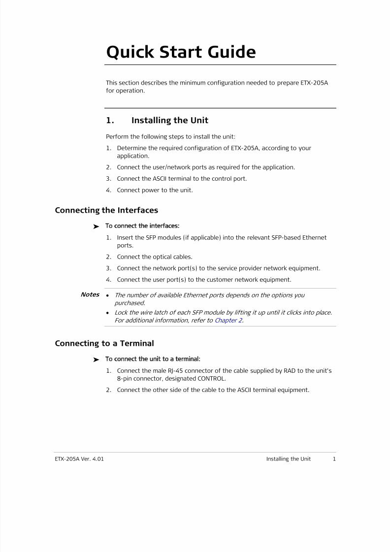
Quick Start Guide
This section describes the minimum configuration needed to prepare ETX-205A
for operation.
1. Installing the Unit
Perform the following steps to install the unit:
1. Determine the required configuration of ETX-205A, according to your
application.
2. Connect the user/network ports as required for the application.
3. Connect the ASCII terminal to the control port.
4. Connect power to the unit.
Connecting the Interfaces
To connect the interfaces:
1. Insert the SFP modules (if applicable) into the relevant SFP-based Ethernet
ports.
2. Connect the optical cables.
3. Connect the network port(s) to the service provider network equipment.
4. Connect the user port(s) to the customer network equipment.
• The number of available Ethernet ports depends on the options you
purchased.
• Lock the wire latch of each SFP module by lifting it up until it clicks into place.
For additional information, refer to Chapter 2 .
Connecting to a Terminal
To connect the unit to a terminal:
1. Connect the male RJ-45 connector of the cable supplied by RAD to the unit's
8-pin connector, designated CONTROL.
2. Connect the other side of the cable to the ASCII terminal equipment.
Notes
7/25/2019 Manual ETX-205A
http://slidepdf.com/reader/full/manual-etx-205a 24/409
7/25/2019 Manual ETX-205A
http://slidepdf.com/reader/full/manual-etx-205a 25/409
Installation and Operation Manual Quick Start Guide
ETX-205A Ver. 4.01 Configuring the Unit for Management 3
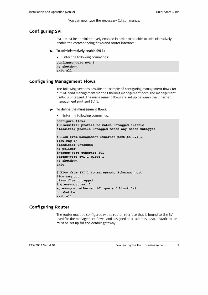
You can now type the necessary CLI commands.
Configuring SVI
SVI 1 must be administratively enabled in order to be able to administratively
enable the corresponding flows and router interface.
To administratively enable SVI 1:
• Enter the following commands:
configure port svi 1
no shutdown
exit all
Configuring Management Flows
The following sections provide an example of configuring management flows for
out-of-band management via the Ethernet management port. The management
traffic is untagged. The management flows are set up between the Ethernetmanagement port and SVI 1.
To define the management flows:
• Enter the following commands:
configure flows
# Classifier profile to match untagged traffic
classifier-profile untagged match-any match untagged
# Flow from management Ethernet port to SVI 1
flow mng_in
classifier untagged
no policer
ingress-port ethernet 101
egress-port svi 1 queue 1
no shutdown
exit
# Flow from SVI 1 to management Ethernet port
flow mng_out
classifier untagged
ingress-port svi 1
egress-port ethernet 101 queue 0 block 0/1
no shutdown
exit all
Configuring Router
The router must be configured with a router interface that is bound to the SVI
used for the management flows, and assigned an IP address. Also, a static route
must be set up for the default gateway.
7/25/2019 Manual ETX-205A
http://slidepdf.com/reader/full/manual-etx-205a 26/409
Quick Start Guide Installation and Operation Manual
4 Verifying Connectivity ETX-205A Ver. 4.01
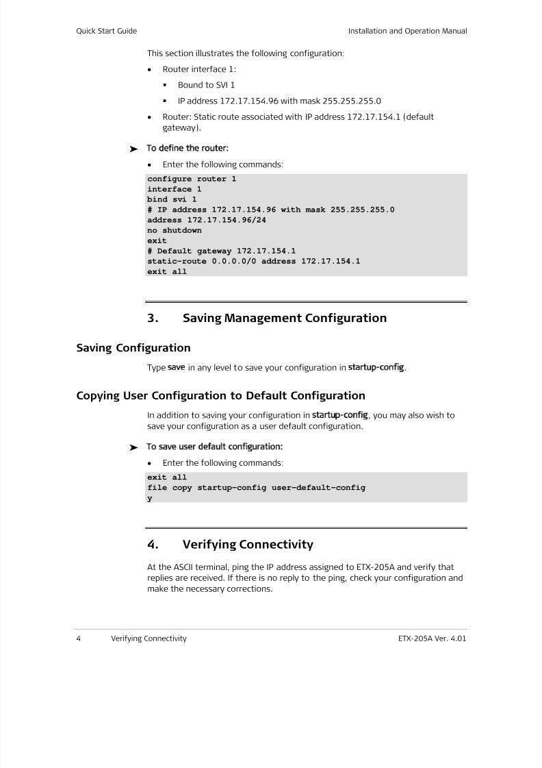
This section illustrates the following configuration:
• Router interface 1:
Bound to SVI 1
IP address 172.17.154.96 with mask 255.255.255.0
• Router: Static route associated with IP address 172.17.154.1 (default
gateway).
To define the router:
• Enter the following commands:
configure router 1
interface 1
bind svi 1
# IP address 172.17.154.96 with mask 255.255.255.0
address 172.17.154.96/24
no shutdown
exit
# Default gateway 172.17.154.1
static-route 0.0.0.0/0 address 172.17.154.1
exit all
3. Saving Management Configuration
Saving Configuration
Type save in any level to save your configuration in startup config.
Copying User Configuration to Default Configuration
In addition to saving your configuration in startup config, you may also wish to
save your configuration as a user default configuration.
To save user default configuration:
• Enter the following commands:
exit all
file copy startup-config user-default-config
y
4. Verifying Connectivity
At the ASCII terminal, ping the IP address assigned to ETX-205A and verify that
replies are received. If there is no reply to the ping, check your configuration and
make the necessary corrections.
7/25/2019 Manual ETX-205A
http://slidepdf.com/reader/full/manual-etx-205a 27/409
ETX-203AX Ver. 4.01 i
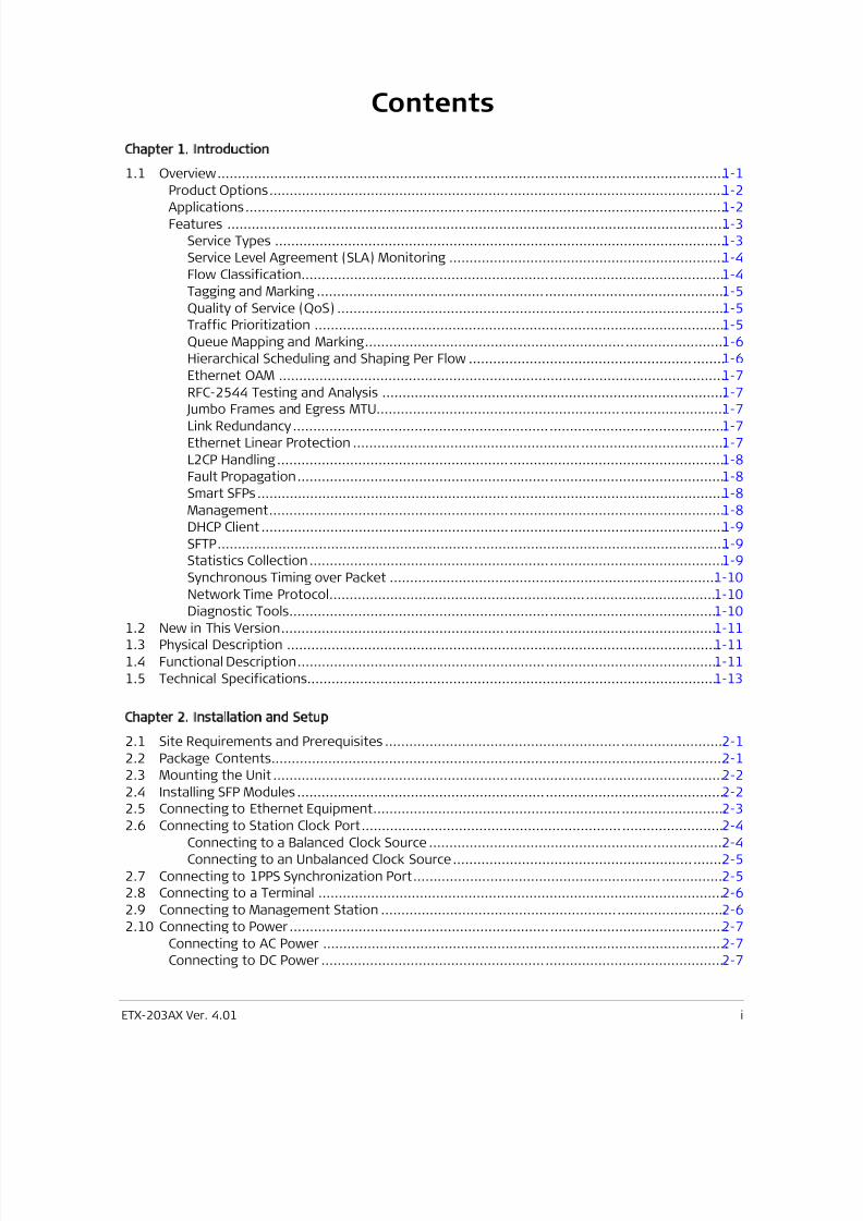
Contents
Chapter 1. Introduction
1.1 Overview .............................................................................................................................. 1-1
Product Options ................................................................................................................. 1-2
Applications ....................................................................................................................... 1-2
Features ............................................................................................................................ 1-3
Service Types ................................................................................................................ 1-3
Service Level Agreement (SLA) Monitoring .................................................................... 1-4
Flow Classification ......................................................................................................... 1-4
Tagging and Marking ..................................................................................................... 1-5
Quality of Service (QoS) ................................................................................................ 1-5
Traffic Prioritization ...................................................................................................... 1-5
Queue Mapping and Marking ......................................................................................... 1-6
Hierarchical Scheduling and Shaping Per Flow ............................................................... 1-6
Ethernet OAM ............................................................................................................... 1-7
RFC-2544 Testing and Analysis ..................................................................................... 1-7
Jumbo Frames and Egress MTU ...................................................................................... 1-7
Link Redundancy ........................................................................................................... 1-7
Ethernet Linear Protection ............................................................................................ 1-7
L2CP Handling ............................................................................................................... 1-8
Fault Propagation .......................................................................................................... 1-8
Smart SFPs .................................................................................................................... 1-8
Management ................................................................................................................. 1-8
DHCP Client ................................................................................................................... 1-9
SFTP .............................................................................................................................. 1-9
Statistics Collection ....................................................................................................... 1-9
Synchronous Timing over Packet ................................................................................. 1-10
Network Time Protocol ................................................................................................ 1-10
Diagnostic Tools .......................................................................................................... 1-10
1.2 New in This Version ............................................................................................................ 1-11
1.3 Physical Description ........................................................................................................... 1-11
1.4 Functional Description ........................................................................................................ 1-11
1.5 Technical Specifications...................................................................................................... 1-13
Chapter 2. Installation and Setup
2.1 Site Requirements and Prerequisites .................................................................................... 2-1
2.2 Package Contents................................................................................................................. 2-1
2.3 Mounting the Unit ................................................................................................................ 2-2
2.4 Installing SFP Modules .......................................................................................................... 2-2
2.5
Connecting to Ethernet Equipment ....................................................................................... 2-3 2.6 Connecting to Station Clock Port .......................................................................................... 2-4
Connecting to a Balanced Clock Source ......................................................................... 2-4
Connecting to an Unbalanced Clock Source ................................................................... 2-5
2.7 Connecting to 1PPS Synchronization Port ............................................................................. 2-5
2.8 Connecting to a Terminal ..................................................................................................... 2-6
2.9 Connecting to Management Station ..................................................................................... 2-6
2.10 Connecting to Power ............................................................................................................ 2-7
Connecting to AC Power .................................................................................................... 2-7
Connecting to DC Power .................................................................................................... 2-7
7/25/2019 Manual ETX-205A
http://slidepdf.com/reader/full/manual-etx-205a 28/409
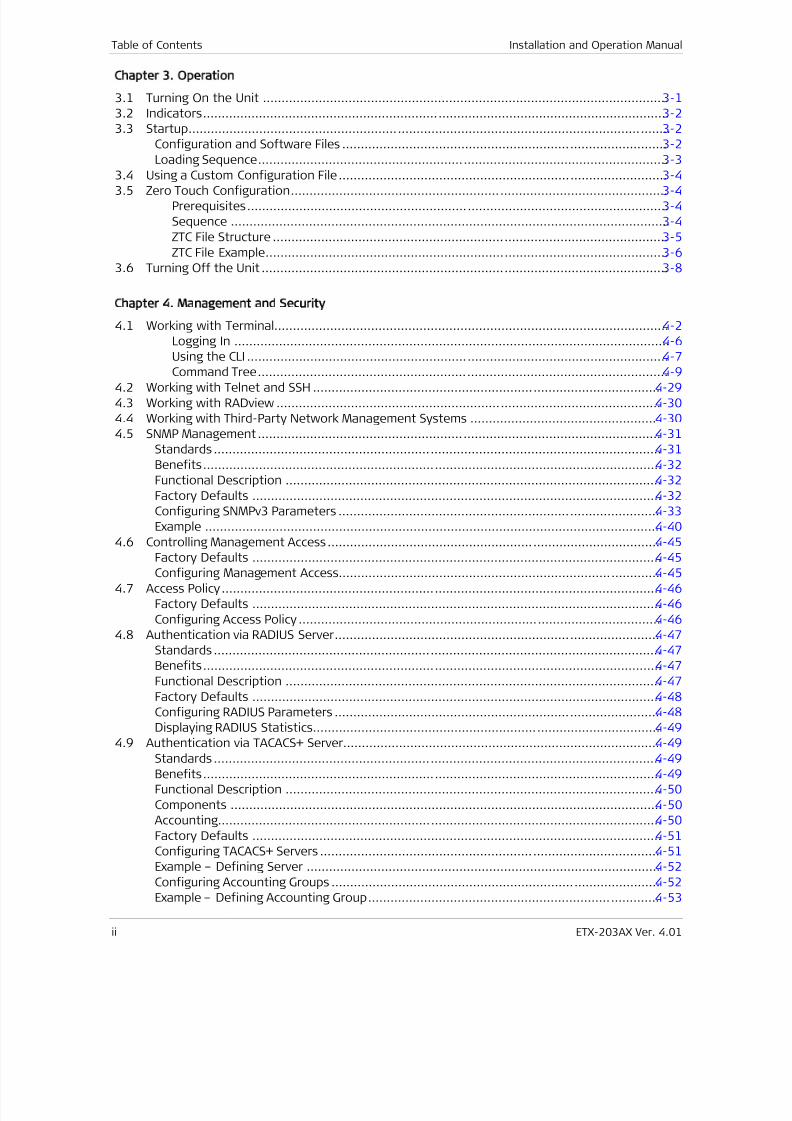
Table of Contents Installation and Operation Manual
ii ETX-203AX Ver. 4.01
Chapter 3. Operation
3.1 Turning On the Unit ............................................................................................................. 3-1
3.2 Indicators ............................................................................................................................. 3-2
3.3 Startup ................................................................................................................................. 3-2
Configuration and Software Files ....................................................................................... 3-2
Loading Sequence .............................................................................................................. 3-3
3.4 Using a Custom Configuration File ........................................................................................ 3-4
3.5
Zero Touch Configuration ..................................................................................................... 3-4
Prerequisites ................................................................................................................. 3-4
Sequence ...................................................................................................................... 3-4
ZTC File Structure .......................................................................................................... 3-5
ZTC File Example ............................................................................................................ 3-6
3.6 Turning Off the Unit ............................................................................................................. 3-8
Chapter 4. Management and Security
4.1 Working with Terminal.......................................................................................................... 4-2
Logging In ..................................................................................................................... 4-6
Using the CLI ................................................................................................................. 4-7
Command Tree .............................................................................................................. 4-9 4.2 Working with Telnet and SSH ............................................................................................. 4-29
4.3 Working with RADview ....................................................................................................... 4-30
4.4 Working with Third-Party Network Management Systems .................................................. 4-30
4.5 SNMP Management ............................................................................................................ 4-31
Standards ........................................................................................................................ 4-31
Benefits ........................................................................................................................... 4-32
Functional Description ..................................................................................................... 4-32
Factory Defaults .............................................................................................................. 4-32
Configuring SNMPv3 Parameters ...................................................................................... 4-33
Example ........................................................................................................................... 4-40
4.6 Controlling Management Access ......................................................................................... 4-45
Factory Defaults .............................................................................................................. 4-45 Configuring Management Access...................................................................................... 4-45
4.7 Access Policy ...................................................................................................................... 4-46
Factory Defaults .............................................................................................................. 4-46
Configuring Access Policy ................................................................................................. 4-46
4.8 Authentication via RADIUS Server ....................................................................................... 4-47
Standards ........................................................................................................................ 4-47
Benefits ........................................................................................................................... 4-47
Functional Description ..................................................................................................... 4-47
Factory Defaults .............................................................................................................. 4-48
Configuring RADIUS Parameters ....................................................................................... 4-48
Displaying RADIUS Statistics ............................................................................................. 4-49
4.9
Authentication via TACACS+ Server..................................................................................... 4-49 Standards ........................................................................................................................ 4-49
Benefits ........................................................................................................................... 4-49
Functional Description ..................................................................................................... 4-50
Components .................................................................................................................... 4-50
Accounting ....................................................................................................................... 4-50
Factory Defaults .............................................................................................................. 4-51
Configuring TACACS+ Servers ........................................................................................... 4-51
Example – Defining Server ............................................................................................... 4-52
Configuring Accounting Groups ........................................................................................ 4-52
Example – Defining Accounting Group .............................................................................. 4-53
7/25/2019 Manual ETX-205A
http://slidepdf.com/reader/full/manual-etx-205a 29/409
Installation and Operation Manual Table of Contents
ETX-203AX Ver. 4.01 iii
4.10 Terminal Control Port ......................................................................................................... 4-53
Factory Defaults .............................................................................................................. 4-53
Configuring Control Port Parameters ................................................................................ 4-53
4.11 User Access ........................................................................................................................ 4-54
Factory Defaults .............................................................................................................. 4-55
Configuring Users ............................................................................................................ 4-55
Example – Defining Users................................................................................................. 4-55
Example – Displaying Users .............................................................................................. 4-57
Chapter 5. Services
Ethernet User Traffic ......................................................................................................... 5-1
Network to User ........................................................................................................... 5-1
User to Network ........................................................................................................... 5-2
TDM User Traffic ................................................................................................................ 5-4
TDM Network to Ethernet User ..................................................................................... 5-4
TDM User to Network .................................................................................................... 5-7
Chapter 6. Ports
6.1
Ethernet Ports ...................................................................................................................... 6-1
Factory Defaults ................................................................................................................ 6-2
Configuring Ethernet Port Parameters ................................................................................ 6-3
Setting Second Network Interface as Network or User Port ............................................... 6-5
Example ........................................................................................................................ 6-6
Displaying Ethernet Port Status ......................................................................................... 6-6
Examples ....................................................................................................................... 6-7
Testing Ethernet Ports ....................................................................................................... 6-7
Example ........................................................................................................................ 6-8
Displaying Ethernet Port Statistics ..................................................................................... 6-8
Setting Sampling Interval for Port Statistics .................................................................. 6-8
Displaying Port Statistics ............................................................................................... 6-9
Example ........................................................................................................................ 6-9
Displaying Layer-2 Control Processing Statistics .......................................................... 6-11
Example ...................................................................................................................... 6-11
Clearing Statistics ........................................................................................................ 6-11
6.2 Smart SFPs ......................................................................................................................... 6-11
Benefits ........................................................................................................................... 6-12
Factory Defaults .............................................................................................................. 6-12
Configuring Smart SFPs .................................................................................................... 6-12
Example ........................................................................................................................... 6-13
6.3 E1 Ports ............................................................................................................................. 6-14
Standards and MIBs ......................................................................................................... 6-14
Benefits ........................................................................................................................... 6-15
Functional Description ..................................................................................................... 6-15
Factory Defaults .............................................................................................................. 6-15
Configuring E1 Ports ........................................................................................................ 6-15
6.4 T1 Ports ............................................................................................................................. 6-17
Standards and MIBs ......................................................................................................... 6-17
Benefits ........................................................................................................................... 6-17
Functional Description ..................................................................................................... 6-17
Factory Defaults .............................................................................................................. 6-17
Configuring T1 Ports ........................................................................................................ 6-17
6.5 E3 Ports ............................................................................................................................. 6-19
7/25/2019 Manual ETX-205A
http://slidepdf.com/reader/full/manual-etx-205a 30/409
Table of Contents Installation and Operation Manual
iv ETX-203AX Ver. 4.01
Standards and MIBs ......................................................................................................... 6-19
Benefits ........................................................................................................................... 6-19
Functional Description ..................................................................................................... 6-19
Factory Defaults .............................................................................................................. 6-19
Configuring E3 Ports ........................................................................................................ 6-20
6.6 T3 Ports ............................................................................................................................. 6-21
Standards and MIBs ......................................................................................................... 6-21
Benefits ........................................................................................................................... 6-21 Functional Description ..................................................................................................... 6-21
Factory Defaults .............................................................................................................. 6-21
Configuring T3 Ports ........................................................................................................ 6-22
6.7 SDH/SONET Ports ............................................................................................................... 6-23
Standards and MIBs ......................................................................................................... 6-23
Benefits ........................................................................................................................... 6-23
Functional Description ..................................................................................................... 6-23
Factory Defaults .............................................................................................................. 6-23
Configuring SDH/SONET Ports .......................................................................................... 6-24
6.8 GFP Ports ........................................................................................................................... 6-25
Factory Defaults .............................................................................................................. 6-25
Configuring GFP Logical Ports ........................................................................................... 6-25 Example ........................................................................................................................... 6-26
6.9 Logical MAC Ports ............................................................................................................... 6-27
Factory Defaults .............................................................................................................. 6-27
Configuring Logical MAC ports .......................................................................................... 6-27
Example ........................................................................................................................... 6-28
6.10 Service Virtual Interfaces .................................................................................................... 6-29
Configuring Service Virtual Interfaces ............................................................................... 6-29
Chapter 7. Resiliency
7.1 Ethernet Linear Protection ................................................................................................... 7-1
Standards .......................................................................................................................... 7-1
Benefits ............................................................................................................................. 7-1
Functional Description ....................................................................................................... 7-1
ETP Flow Attributes ....................................................................................................... 7-2
EVC Protection Switching............................................................................................... 7-2
Master and Slave ETPs ................................................................................................... 7-3
EVC and OAM ................................................................................................................ 7-3
EVC Fault Propagation ................................................................................................... 7-3
EVC Loopback ................................................................................................................ 7-3
Factory Defaults ................................................................................................................ 7-3
Configuring ETPs ................................................................................................................ 7-4
Configuring ETP Ports ......................................................................................................... 7-4
Example ........................................................................................................................ 7-5
Configuring ETP Protection ................................................................................................. 7-5
Example ........................................................................................................................ 7-6
7.2 Fault Propagation ................................................................................................................. 7-7
Standards .......................................................................................................................... 7-7
Benefits ............................................................................................................................. 7-7
Functional Description ....................................................................................................... 7-7
Factory Defaults ................................................................................................................ 7-8
Configuring Fault Propagation ............................................................................................ 7-8
Adding Fault Propagation Entry ..................................................................................... 7-9
Configuring Fault Propagation Parameters .................................................................... 7-9
7/25/2019 Manual ETX-205A
http://slidepdf.com/reader/full/manual-etx-205a 31/409
Installation and Operation Manual Table of Contents
ETX-203AX Ver. 4.01 v
Example ...................................................................................................................... 7-10
Disabling Fault Propagation ......................................................................................... 7-11
7.3 Network Interface Redundancy .......................................................................................... 7-12
Standards and MIBs ......................................................................................................... 7-12
Benefits ........................................................................................................................... 7-12
Functional Description ..................................................................................................... 7-12
Link Aggregation ......................................................................................................... 7-12
1:1 Bidirectional Redundancy ...................................................................................... 7-13 Factory Defaults .......................................................................................................... 7-14
Configuring LAG ............................................................................................................... 7-14
Example ...................................................................................................................... 7-16
Configuring Link Protection .............................................................................................. 7-18
Example ...................................................................................................................... 7-20
Chapter 8. Networking
8.1 Flows ................................................................................................................................... 8-1
Standards .......................................................................................................................... 8-1
Benefits ............................................................................................................................. 8-1
Functional Description ....................................................................................................... 8-1
Factory Defaults ................................................................................................................ 8-8
Defining Classifier Profiles ................................................................................................. 8-9
Examples ....................................................................................................................... 8-9
Configuring Flows ............................................................................................................ 8-10
Examples ..................................................................................................................... 8-13
Testing Flows ................................................................................................................... 8-16
Displaying Flow Statistics ................................................................................................. 8-16
Example ...................................................................................................................... 8-17
8.2 Layer-2 Control Processing ................................................................................................. 8-18
Standards ........................................................................................................................ 8-19
Benefits ........................................................................................................................... 8-19
Factory Defaults .............................................................................................................. 8-19
Adding Layer 2 Control Processing Profiles ...................................................................... 8-19
Deleting Layer 2 Control Processing Profiles .................................................................... 8-19
Configuring Layer 2 Control Processing Profile Parameters .............................................. 8-20
Example ........................................................................................................................... 8-21
8.3 OAM ................................................................................................................................... 8-22
OAM CFM (Connectivity Fault Management) ..................................................................... 8-22
Standards ................................................................................................................... 8-22
Benefits ...................................................................................................................... 8-22
Functional Description................................................................................................. 8-22
Factory Defaults .......................................................................................................... 8-23
Configuring OAM CFM General Parameters .................................................................. 8-25
Configuring Maintenance Domains .............................................................................. 8-26
Configuring Maintenance Associations ........................................................................ 8-27
Configuring Maintenance Endpoints ............................................................................ 8-29
Configuring Maintenance Intermediate Points ............................................................. 8-31
Examples ..................................................................................................................... 8-31
Configuring Maintenance Endpoint Services ................................................................ 8-33
Configuring Destination NEs ........................................................................................ 8-35
Example ...................................................................................................................... 8-36
Configuring OAM CFM Service Event Reporting ............................................................ 8-36
Example ...................................................................................................................... 8-39
Displaying OAM CFM Statistics ..................................................................................... 8-41
7/25/2019 Manual ETX-205A
http://slidepdf.com/reader/full/manual-etx-205a 32/409
Table of Contents Installation and Operation Manual
vi ETX-203AX Ver. 4.01
Examples ..................................................................................................................... 8-45
Performing OAM Loopback .......................................................................................... 8-52
Performing OAM Link Trace ......................................................................................... 8-53
OAM EFM ......................................................................................................................... 8-53
Standards ................................................................................................................... 8-54
Benefits ...................................................................................................................... 8-54
Functional Description................................................................................................. 8-54
Factory Defaults .......................................................................................................... 8-54 Configuring OAM EFM .................................................................................................. 8-54
Example ...................................................................................................................... 8-56
8.4 Quality of Service (QoS) ..................................................................................................... 8-56
Standards ........................................................................................................................ 8-57
Benefits ........................................................................................................................... 8-57
Factory Defaults .............................................................................................................. 8-57
Functional Description ..................................................................................................... 8-57
Queue Mapping Profiles ................................................................................................... 8-57
Factory Defaults .......................................................................................................... 8-58
Adding Queue Mapping Profiles ................................................................................... 8-59
Configuring Queue Mappings ...................................................................................... 8-59
Examples ..................................................................................................................... 8-60 CoS Mapping Profiles ....................................................................................................... 8-61
Factory Defaults .......................................................................................................... 8-61
Configuring CoS Mapping Profiles ................................................................................ 8-62
Example ...................................................................................................................... 8-62
Marking Profiles ............................................................................................................... 8-63
Factory Defaults .......................................................................................................... 8-63
Configuring Marking Profiles ........................................................................................ 8-63
Bandwidth Profiles ........................................................................................................... 8-64
Factory Defaults .......................................................................................................... 8-64
Configuring Shaper Profiles ......................................................................................... 8-65
Configuring Policer Profiles .......................................................................................... 8-65
Configuring Policer Aggregates .................................................................................... 8-68 Queue Block Profiles ........................................................................................................ 8-69
Factory Defaults .......................................................................................................... 8-70
Adding Queue Block Profiles ........................................................................................ 8-70
Configuring Queue Block Profile Parameters................................................................ 8-70
Example ...................................................................................................................... 8-71
Queue Group Profiles ....................................................................................................... 8-72
Adding Queue Group Profiles ...................................................................................... 8-72
Configuring Queue Group Parameters ......................................................................... 8-72
WRED Profiles .................................................................................................................. 8-73
Factory Defaults .......................................................................................................... 8-73
Configuring WRED Profiles ........................................................................................... 8-74
Example ...................................................................................................................... 8-74
8.5 Router ................................................................................................................................ 8-74
Benefits ........................................................................................................................... 8-75
Factory Default ................................................................................................................ 8-75
Functional Description ..................................................................................................... 8-75
Configuring the Router .................................................................................................... 8-75
Chapter 9. Timing and Synchronization
9.1 Clock Selection ..................................................................................................................... 9-1
Standards .......................................................................................................................... 9-1
7/25/2019 Manual ETX-205A
http://slidepdf.com/reader/full/manual-etx-205a 33/409
Installation and Operation Manual Table of Contents
ETX-203AX Ver. 4.01 vii
Benefits ............................................................................................................................. 9-1
Functional Description ....................................................................................................... 9-1
Clock Domain ..................................................................................................................... 9-1
Factory Defaults ............................................................................................................ 9-3
Configuring the Clock Domain ....................................................................................... 9-3
Clock Sources ..................................................................................................................... 9-5
Factory Defaults ............................................................................................................ 9-5
Configuring the Clock Sources ....................................................................................... 9-5 Displaying Clock Source Statistics .................................................................................. 9-7
Example ............................................................................................................................. 9-7
Recovered Clock ................................................................................................................. 9-8
Standards ..................................................................................................................... 9-8
Benefits ........................................................................................................................ 9-8
Functional Description................................................................................................... 9-8
Configuring the Recovered Clock ................................................................................... 9-9
Station Clock .................................................................................................................... 9-10
9.2 Date and Time .................................................................................................................... 9-11
Setting the Date and Time ............................................................................................... 9-11
Example ...................................................................................................................... 9-12
Displaying the Date and Time .......................................................................................... 9-12 Working with SNTP........................................................................................................... 9-12
Factory Defaults .......................................................................................................... 9-12
Configuring SNTP Parameters ...................................................................................... 9-13
Defining SNTP Servers ................................................................................................. 9-13
Configuring SNTP Server Parameters ........................................................................... 9-13
Example ...................................................................................................................... 9-14
Chapter 10. Administration
10.1 Confirming Startup Configuration ....................................................................................... 10-1
10.2 Device Information ............................................................................................................. 10-2
Example ........................................................................................................................... 10-2
10.3
Environment ....................................................................................................................... 10-3
Example ........................................................................................................................... 10-3
10.4 CPU and Memory Utilization ............................................................................................... 10-3
10.5 File Operations ................................................................................................................... 10-4
Downloading/Uploading Files ........................................................................................... 10-5
SFTP Application .......................................................................................................... 10-5
TFTP Application .......................................................................................................... 10-7
Using CLI to Download/Upload Files ............................................................................... 10-10
Example – Download via TFTP ................................................................................... 10-10
Example – Download via SFTP ................................................................................... 10-10
Example – Upload via TFTP ........................................................................................ 10-11
Example – Upload via SFTP ........................................................................................ 10-11
Copying Files Within Device ............................................................................................ 10-11
Example .................................................................................................................... 10-11
Displaying Copy Status ................................................................................................... 10-11
Displaying Information on Files ...................................................................................... 10-12
Example .................................................................................................................... 10-12
Example .................................................................................................................... 10-13
Example .................................................................................................................... 10-13
Deleting Files ................................................................................................................. 10-14
Example .................................................................................................................... 10-14
10.6 Inventory.......................................................................................................................... 10-14
7/25/2019 Manual ETX-205A
http://slidepdf.com/reader/full/manual-etx-205a 34/409
Table of Contents Installation and Operation Manual
viii ETX-203AX Ver. 4.01
Standards and MIBs ....................................................................................................... 10-14
Benefits ......................................................................................................................... 10-15
Displaying Inventory Information ................................................................................... 10-15
Setting Administrative Inventory Information ................................................................. 10-16
Example ......................................................................................................................... 10-17
10.7 Reset ............................................................................................................................... 10-20
Resetting to Factory Defaults ........................................................................................ 10-20
Resetting to User Defaults ............................................................................................. 10-21 Restarting the Unit ........................................................................................................ 10-21
10.8 Saving Configuration ........................................................................................................ 10-22
10.9 Statistics Clearing ............................................................................................................. 10-22
10.10 Syslog ....................................................................................................................... 10-22
Configuring Syslog Parameters ....................................................................................... 10-22
Displaying Syslog Statistics ............................................................................................ 10-23
10.11 Temperature Threshold ............................................................................................. 10-24
Example ......................................................................................................................... 10-25
Chapter 11. Monitoring and Diagnostics
11.1
Detecting Problems ............................................................................................................ 11-1
LEDs ................................................................................................................................ 11-1
Alarms and Traps ............................................................................................................. 11-1
Statistic Counters ............................................................................................................ 11-1
11.2 Handling Alarms and Events ............................................................................................... 11-2
Configuring Alarm and Event Properties ........................................................................... 11-2
Working with Alarm and Event Logs ................................................................................. 11-4
Alarms and Events Supported by Device .......................................................................... 11-5
Traps Supported by Device .............................................................................................. 11-9
11.3 Troubleshooting ............................................................................................................... 11-13
Troubleshooting Chart ................................................................................................... 11-13
11.4 Performing Diagnostic Tests ............................................................................................. 11-15
RFC-2544 Testing .......................................................................................................... 11-15
Standards ................................................................................................................. 11-15
Benefits .................................................................................................................... 11-15
Functional Description............................................................................................... 11-15
Factory Defaults ........................................................................................................ 11-16
Performing Tests ....................................................................................................... 11-16
Example .................................................................................................................... 11-19
Running a Ping Test ....................................................................................................... 11-23
Tracing the Route .......................................................................................................... 11-24
11.5 Frequently Asked Questions ............................................................................................. 11-25
11.6 Technical Support ............................................................................................................. 11-25
Chapter 12. Software Upgrade
12.1 Software Upgrade Options ................................................................................................. 12-1
12.2 Prerequisites ...................................................................................................................... 12-1
12.3 Upgrading the Device Software via CLI ............................................................................... 12-2
Verifying the IP Parameters .............................................................................................. 12-2
Pinging the PC .................................................................................................................. 12-3
Activating the SFTP Server ............................................................................................... 12-3
Activating the TFTP Server ............................................................................................... 12-3
Downloading the Software .............................................................................................. 12-3
Installing Software ........................................................................................................... 12-4

7/25/2019 Manual ETX-205A
http://slidepdf.com/reader/full/manual-etx-205a 35/409
Installation and Operation Manual Table of Contents
ETX-203AX Ver. 4.01 ix
Restoring Previous Active Software.................................................................................. 12-5
12.4 Upgrading the Device Software via the Boot Menu............................................................. 12-5
Accessing the Boot Menu ................................................................................................. 12-6
Using the XMODEM Protocol ............................................................................................ 12-7
Using FTP ......................................................................................................................... 12-8
Using TFTP ....................................................................................................................... 12-9
Activating Software ......................................................................................................... 12-9
12.5
Verifying Upgrade Results ................................................................................................ 12-10
Appendix A. Connection Data
Appendix B. Operation, Administration, and Maintenance OAM)
Appendix C. Clock Selection and Management CSM)

7/25/2019 Manual ETX-205A
http://slidepdf.com/reader/full/manual-etx-205a 36/409
Table of Contents Installation and Operation Manual
x ETX-203AX Ver. 4.01

7/25/2019 Manual ETX-205A
http://slidepdf.com/reader/full/manual-etx-205a 37/409
ETX-205A Ver. 4.01 Overview 1-1
Chapter 1
Introduction
1.1 Overview
ETX-205A is a carrier Ethernet demarcation device owned and operated by the
service provider and installed at the customer premises, delivering SLA-based
Ethernet business services to the customer premises over native Ethernet access.
In addition, it functions as a mobile demarcation device (MDD), efficiently
managing mobile broadband traffic between the IP NodeB/ LTE eNodeB and the
network core with SLA assurance.
Furthermore, incorporating RAD’s SyncToP platform of synchronization and timing
over packet feature set, ETX-205A utilizes standard technologies such as 1588v2
and Synchronous Ethernet to ensure highly accurate traffic delivery in
packet-based mobile backhaul networks.
The device delivers Ethernet E-line services (EPL and EVPL) and is MEF 9 and
MEF 14 certified.
Incoming customer traffic is classified and mapped according to port-based
(all-in-one) bundling or by user port and CE VLAN-ID, VLAN priority, DSCP, IP
precedence, MAC, IP address, and Ethertype. This offers operators the flexibility
to differentiate services using different kinds of classification methods, police the
traffic, and enforce SLA per service.
ETX-205A supports powerful bandwidth profiles such as CIR/CBS and EIR/EBS for
differentiated Ethernet services and includes comprehensive Ethernet OAM
(Operation, Administration, and Maintenance) functionality together with SLA
monitoring.
Two Ethernet network ports as well as up to four Ethernet subscriber ports use
SFP/UTP combo ports that can operate as fiber optic SFP-based interfaces or
electrical RJ-45 interfaces.
The SFP/UTP combo ports are FE/GbE auto detecting and can accommodate a
wide range of Fast Ethernet and Gigabit Ethernet SFP transceivers, allowing
service providers to seamlessly connect customers located at different distances
from the device.
The network ports support 1:1 or LAG link aggregation. At the physical layer,
ETX-205A supports autonegotiation and fault propagation.
The unit can be managed via a local terminal port, via a dedicated out-of-band
Ethernet port. Additionally, ETX-205A can be managed inband, via a user or
network port.
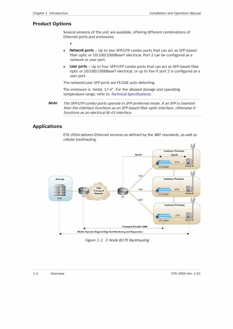
7/25/2019 Manual ETX-205A
http://slidepdf.com/reader/full/manual-etx-205a 38/409
Chapter 1 Introduction Installation and Operation Manual
1-2 Overview ETX-205A Ver. 4.01
Product Options
Several versions of the unit are available, offering different combinations of
Ethernet ports and enclosures.
• Network ports – Up to two SFP/UTP combo ports that can act as SFP-based
fiber optic or 10/100/1000BaseT electrical. Port 2 can be configured as anetwork or user port.
• User ports – Up to four SFP/UTP combo ports that can act as SFP-based fiber
optic or 10/100/1000BaseT electrical, or up to five if port 2 is configured as a
user port.
The network/user SFP ports are FE/GbE auto detecting.
The enclosure is metal, 17.4”. For the allowed storage and operating
temperature range, refer to Technical Specifications .
The SFP/UTP combo ports operate in SFP-preferred mode. If an SFP is inserted
then the interface functions as an SFP-based fiber optic interface, otherwise itfunctions as an electrical RJ-45 interface.
Applications
ETX-205A delivers Ethernet services as defined by the MEF standards, as well as
cellular backhauling.
Figure 1-1. E-Node B/LTE Backhauling
Note
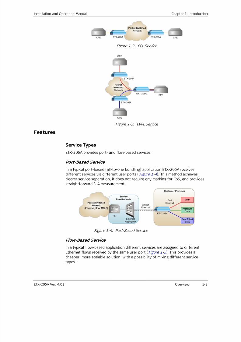
7/25/2019 Manual ETX-205A
http://slidepdf.com/reader/full/manual-etx-205a 39/409
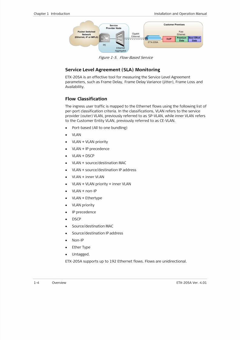
7/25/2019 Manual ETX-205A
http://slidepdf.com/reader/full/manual-etx-205a 40/409
Chapter 1 Introduction Installation and Operation Manual
1-4 Overview ETX-205A Ver. 4.01
Figure 1-5. Flow-Based Service
Service Level Agreement (SLA) Monitoring
ETX-205A is an effective tool for measuring the Service Level Agreement
parameters, such as Frame Delay, Frame Delay Variance (jitter), Frame Loss and
Availability.
Flow Classification
The ingress user traffic is mapped to the Ethernet flows using the following list of
per-port classification criteria. In the classifications, VLAN refers to the serviceprovider (outer) VLAN, previously referred to as SP-VLAN, while inner VLAN refers
to the Customer Entity VLAN, previously referred to as CE-VLAN.
• Port-based (All to one bundling)
• VLAN
• VLAN + VLAN priority
• VLAN + IP precedence
• VLAN + DSCP
• VLAN + source/destination MAC
• VLAN + source/destination IP address
• VLAN + inner VLAN
• VLAN + VLAN priority + inner VLAN
• VLAN + non-IP
• VLAN + Ethertype
• VLAN priority
• IP precedence
• DSCP
• Source/destination MAC
• Source/destination IP address
• Non-IP
• Ether Type
• Untagged.
ETX-205A supports up to 192 Ethernet flows. Flows are unidirectional.
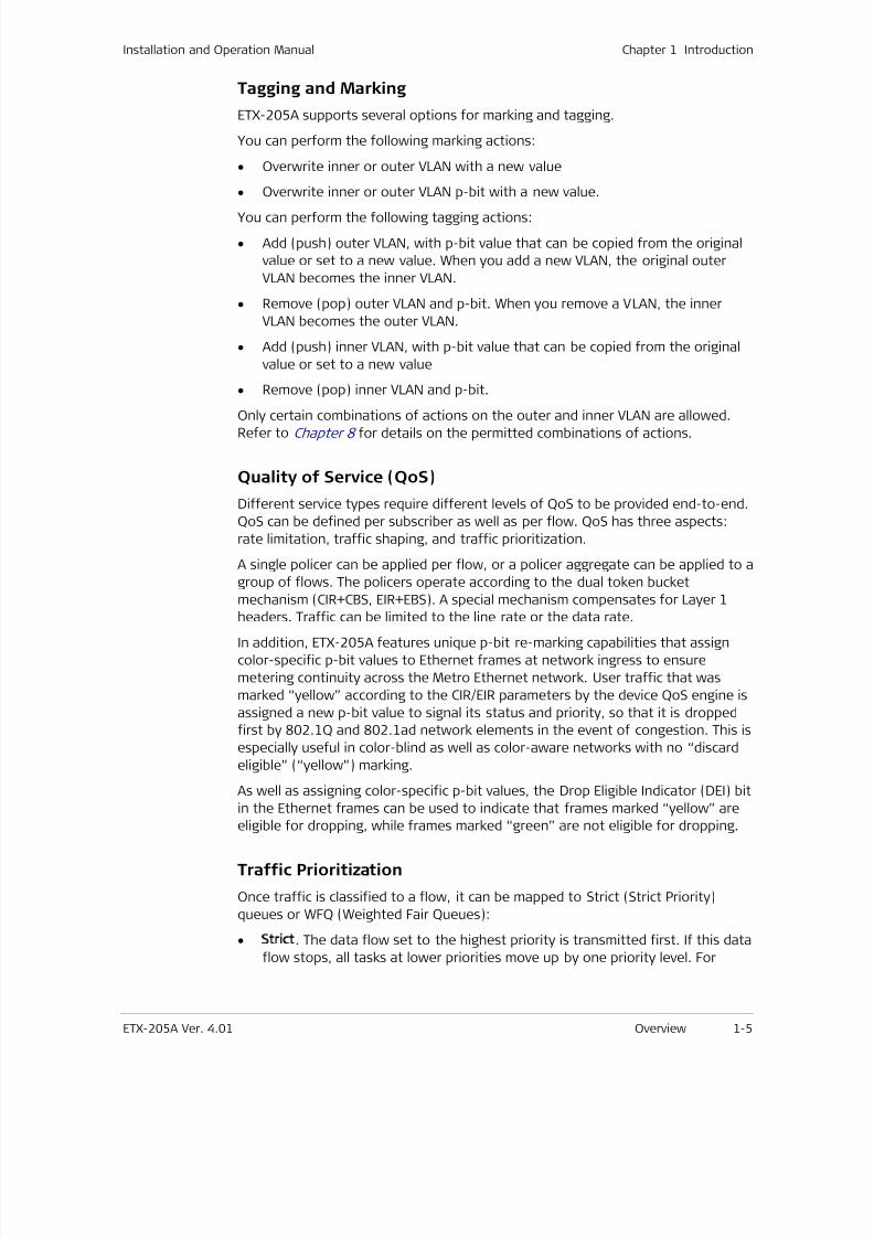
7/25/2019 Manual ETX-205A
http://slidepdf.com/reader/full/manual-etx-205a 41/409
Installation and Operation Manual Chapter 1 Introduction
ETX-205A Ver. 4.01 Overview 1-5
Tagging and Marking
ETX-205A supports several options for marking and tagging.
You can perform the following marking actions:
• Overwrite inner or outer VLAN with a new value
• Overwrite inner or outer VLAN p-bit with a new value.
You can perform the following tagging actions:
• Add (push) outer VLAN, with p-bit value that can be copied from the original
value or set to a new value. When you add a new VLAN, the original outer
VLAN becomes the inner VLAN.
• Remove (pop) outer VLAN and p-bit. When you remove a VLAN, the inner
VLAN becomes the outer VLAN.
• Add (push) inner VLAN, with p-bit value that can be copied from the original
value or set to a new value
• Remove (pop) inner VLAN and p-bit.
Only certain combinations of actions on the outer and inner VLAN are allowed.Refer to Chapter 8 for details on the permitted combinations of actions.
Quality of Service (QoS)
Different service types require different levels of QoS to be provided end-to-end.
QoS can be defined per subscriber as well as per flow. QoS has three aspects:
rate limitation, traffic shaping, and traffic prioritization.
A single policer can be applied per flow, or a policer aggregate can be applied to a
group of flows. The policers operate according to the dual token bucket
mechanism (CIR+CBS, EIR+EBS). A special mechanism compensates for Layer 1
headers. Traffic can be limited to the line rate or the data rate.
In addition, ETX-205A features unique p-bit re-marking capabilities that assign
color-specific p-bit values to Ethernet frames at network ingress to ensure
metering continuity across the Metro Ethernet network. User traffic that was
marked “yellow” according to the CIR/EIR parameters by the device QoS engine is
assigned a new p-bit value to signal its status and priority, so that it is dropped
first by 802.1Q and 802.1ad network elements in the event of congestion. This is
especially useful in color-blind as well as color-aware networks with no “discard
eligible” (“yellow”) marking.
As well as assigning color-specific p-bit values, the Drop Eligible Indicator (DEI) bit
in the Ethernet frames can be used to indicate that frames marked “yellow” are
eligible for dropping, while frames marked “green” are not eligible for dropping.
Traffic Prioritization
Once traffic is classified to a flow, it can be mapped to Strict (Strict Priority)
queues or WFQ (Weighted Fair Queues):
• Strict. The data flow set to the highest priority is transmitted first. If this data
flow stops, all tasks at lower priorities move up by one priority level. For
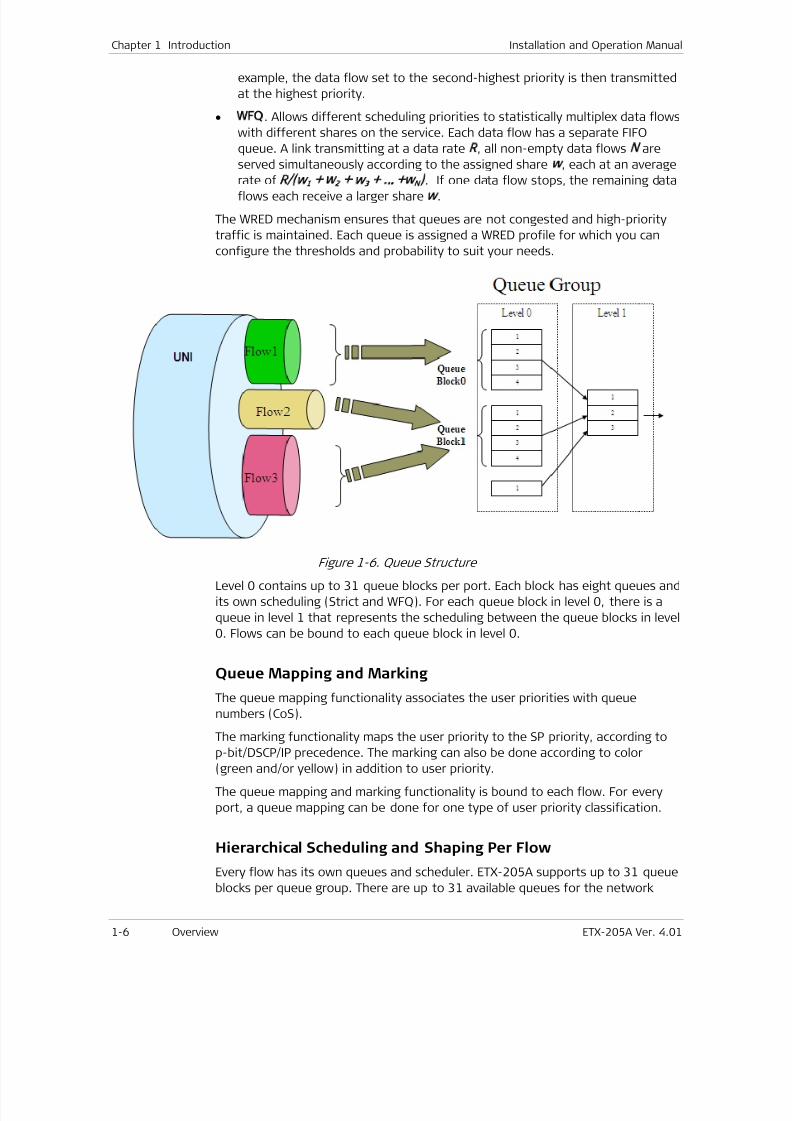
7/25/2019 Manual ETX-205A
http://slidepdf.com/reader/full/manual-etx-205a 42/409
Chapter 1 Introduction Installation and Operation Manual
1-6 Overview ETX-205A Ver. 4.01
example, the data flow set to the second-highest priority is then transmitted
at the highest priority.
• WFQ. Allows different scheduling priorities to statistically multiplex data flows
with different shares on the service. Each data flow has a separate FIFO
queue. A link transmitting at a data rate R, all non-empty data flows N are
served simultaneously according to the assigned share w, each at an average
rate ofR/ w
1
+ w
2
+ w
3
+ … +w
N
)
. If one data flow stops, the remaining dataflows each receive a larger share w.
The WRED mechanism ensures that queues are not congested and high-priority
traffic is maintained. Each queue is assigned a WRED profile for which you can
configure the thresholds and probability to suit your needs.
Figure 1-6. Queue Structure
Level 0 contains up to 31 queue blocks per port. Each block has eight queues and
its own scheduling (Strict and WFQ). For each queue block in level 0, there is a
queue in level 1 that represents the scheduling between the queue blocks in level
0. Flows can be bound to each queue block in level 0.
Queue Mapping and Marking
The queue mapping functionality associates the user priorities with queue
numbers (CoS).
The marking functionality maps the user priority to the SP priority, according to
p-bit/DSCP/IP precedence. The marking can also be done according to color
(green and/or yellow) in addition to user priority.
The queue mapping and marking functionality is bound to each flow. For every
port, a queue mapping can be done for one type of user priority classification.
Hierarchical Scheduling and Shaping Per Flow
Every flow has its own queues and scheduler. ETX-205A supports up to 31 queue
blocks per queue group. There are up to 31 available queues for the network
7/25/2019 Manual ETX-205A
http://slidepdf.com/reader/full/manual-etx-205a 43/409
Installation and Operation Manual Chapter 1 Introduction
ETX-205A Ver. 4.01 Overview 1-7
ports and eight available queues for the user ports. Flows that are in the
direction user port to network port can be bound to one of up to 31 queues, and
flows that are in the direction network port to user port can be bound to one of
eight queues.
Ethernet OAM
Featuring ultra-fast, hardware-based processing capabilities, ETX-205A performsOAM and PM measurements in under 1 microsecond with maximum precision.
ETX-205A provides OAM to monitor and troubleshoot an Ethernet network and
quickly detect failures:
• CFM OAM (End-to-end OAM) based on IEEE 802.1ag-D8 and Y.1731 for
continuity check, non-intrusive loopback, and performance management
• EFM OAM (Link OAM) according to IEEE 802.3-2005 (formerly IEEE 802.3ah)
for remote management and fault indication, including remote loopback,
dying gasp, and MIB parameter retrieval.
RFC-2544 Testing and Analysis
ETX-205A provides BERT testing based on RFC-2544:
• Throughput test – Until binary search convergence
• Packet loss rate – 10% steps
• Latency – Roundtrip frame latency.
Jumbo Frames and Egress MTU
ETX-205A supports large frames of up to 12 Kbytes. The egress MTU can be
defined per port.
Link Redundancy
The unit features network link redundancy in a LAG architecture that supports the
LACP protocol according to 802.3-2005. Dual homing technology in a 1:1
architecture allows ETX-205A to be connected to two different upstream devices.
Link redundancy is available if two ports are configured as network ports.
Ethernet Linear Protection
The device offers protection switching in the following modes for network ports
per ITU-T G.8031:
• 1:1
• Unidirectional
• Using APS messages.
The protection functions for the following topologies:
• EVC protection with one fiber — Both EVCs running on same fiber
• EVC protection with two fibers — Each path on different fiber (dual link)
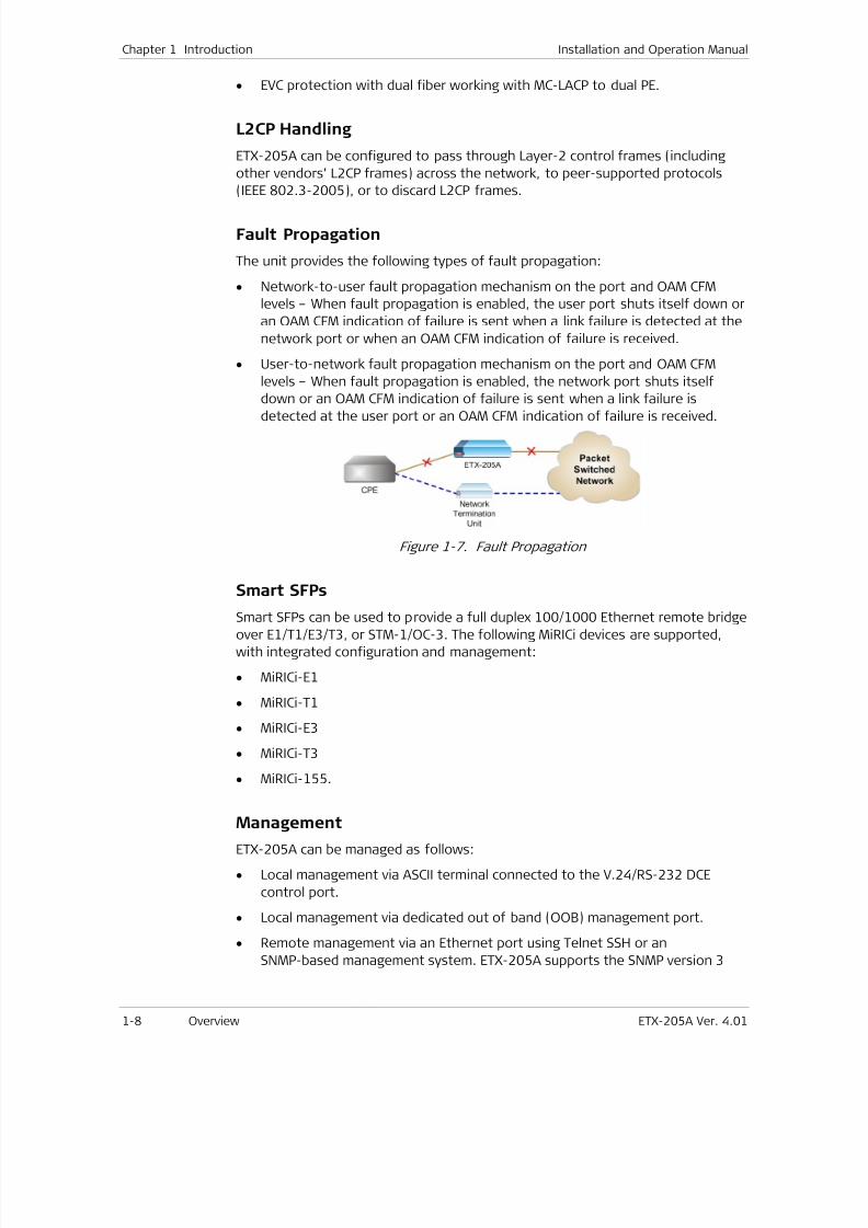
7/25/2019 Manual ETX-205A
http://slidepdf.com/reader/full/manual-etx-205a 44/409
7/25/2019 Manual ETX-205A
http://slidepdf.com/reader/full/manual-etx-205a 45/409
Installation and Operation Manual Chapter 1 Introduction
ETX-205A Ver. 4.01 Overview 1-9
entity, providing secure access to the device by authenticating and encrypting
packets transmitted over the network.
Trap Synchronization
The device sends traps to defined groups of network managers, enabling the
managers to detect when traps have been lost, and request that traps be sent
again.
Command Line Interface
You can create data bases and scripts of commonly used commands and easily
apply them to multiple units in your infrastructure using RAD’s new command line
interface.
Security
To ensure client-server communication privacy and correct user authentication,
ETX-205A supports the security protocols listed below:
• SNMPv3
• RADIUS (client authentication)
• TACACS+ (client authentication)
• SSH for Secure Shell communication session.
Syslog
The syslog protocol is a client/server-type protocol, featuring a standard for
forwarding log messages in an IP network and supports up to four syslog servers
at present. A syslog sender sends a small text message of less than 1024 bytes
to the syslog receiver. Syslog messages are sent via UDP in cleartext.
DHCP Client
When enabled, the DHCP client of ETX-205A requests an IP address, IP mask, and
default gateway from the DHCP server.
SFTP
SFTP (Secure File Transfer Protocol) is supported, to provide secure encrypted file
transfer using SSH.
Statistics Collection
ETX-205A collects performance statistics for the physical layers of the Ethernetports, Ethernet flows, OAM CFM, and Radius.
In addition, ETX-205A provides Rmon Statistics based on RFC 2819. In this
scenario, ETX-205A can send reports when one of the defined counters rises
above or drops below specified thresholds within the sampling period of time.
These reports can be sent as SNMP traps to defined network management
stations and/or written to the event log.
7/25/2019 Manual ETX-205A
http://slidepdf.com/reader/full/manual-etx-205a 46/409
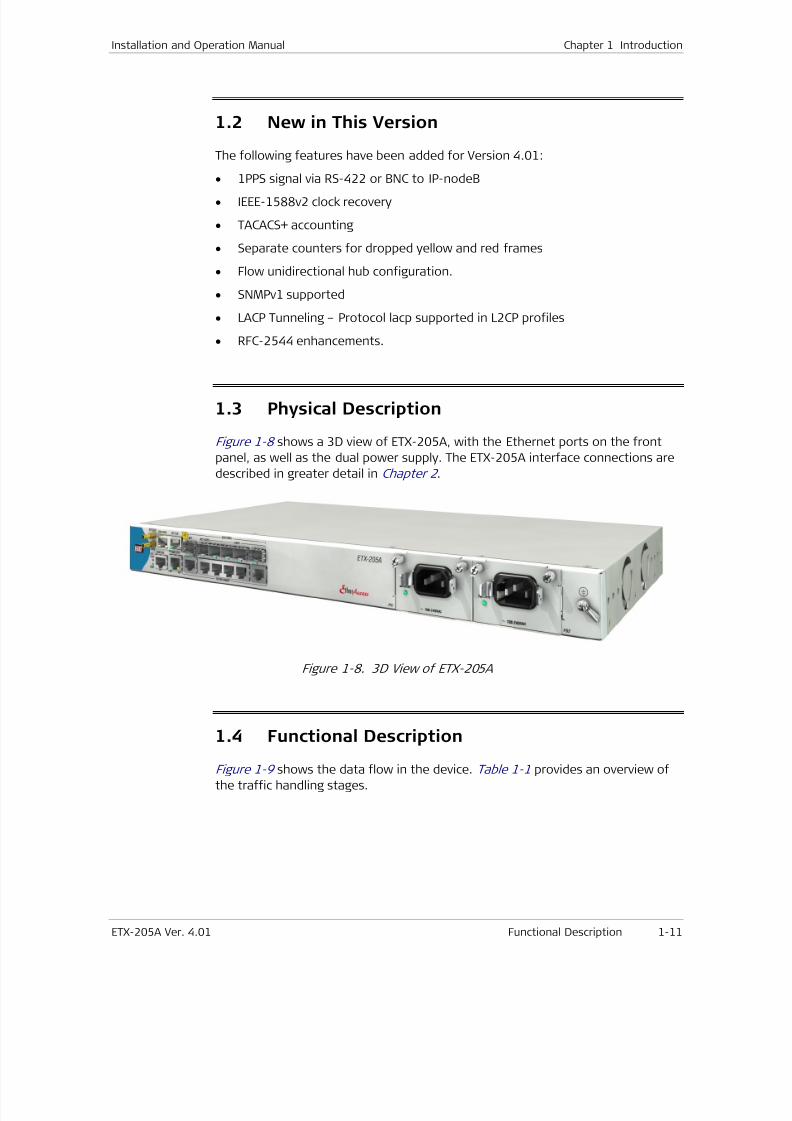
7/25/2019 Manual ETX-205A
http://slidepdf.com/reader/full/manual-etx-205a 47/409
Installation and Operation Manual Chapter 1 Introduction
ETX-205A Ver. 4.01 Functional Description 1-11
1.2 New in This Version
The following features have been added for Version 4.01:
• 1PPS signal via RS-422 or BNC to IP-nodeB
• IEEE-1588v2 clock recovery
• TACACS+ accounting
• Separate counters for dropped yellow and red frames
• Flow unidirectional hub configuration.
• SNMPv1 supported
• LACP Tunneling – Protocol lacp supported in L2CP profiles
• RFC-2544 enhancements.
1.3 Physical Description
Figure 1-8 shows a 3D view of ETX-205A, with the Ethernet ports on the front
panel, as well as the dual power supply. The ETX-205A interface connections are
described in greater detail in Chapter 2 .
Figure 1-8. 3D View of ETX-205A
1.4
Functional DescriptionFigure 1-9 shows the data flow in the device. Table 1-1 provides an overview of
the traffic handling stages.
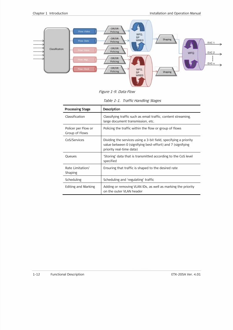
7/25/2019 Manual ETX-205A
http://slidepdf.com/reader/full/manual-etx-205a 48/409
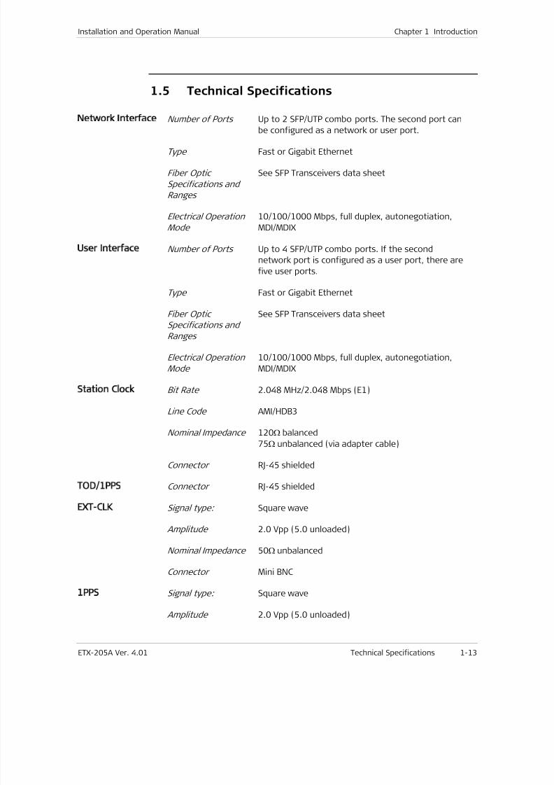
7/25/2019 Manual ETX-205A
http://slidepdf.com/reader/full/manual-etx-205a 49/409
Installation and Operation Manual Chapter 1 Introduction
ETX-205A Ver. 4.01 Technical Specifications 1-13
1.5 Technical Specifications
Network Interface Number of Ports Up to 2 SFP/UTP combo ports. The second port can
be configured as a network or user port.
Type Fast or Gigabit Ethernet
Fiber Optic
Specifications and
Ranges
See SFP Transceivers data sheet
Electrical Operation
Mode
10/100/1000 Mbps, full duplex, autonegotiation,
MDI/MDIX
User Interface Number of Ports Up to 4 SFP/UTP combo ports. If the second
network port is configured as a user port, there arefive user ports.
Type Fast or Gigabit Ethernet
Fiber Optic
Specifications and
Ranges
See SFP Transceivers data sheet
Electrical Operation
Mode
10/100/1000 Mbps, full duplex, autonegotiation,
MDI/MDIX
Station Clock
Bit Rate 2.048 MHz/2.048 Mbps (E1)
Line Code AMI/HDB3
Nominal Impedance 120Ω balanced
75Ω unbalanced (via adapter cable)
Connector RJ-45 shielded
TOD/1PPS Connector RJ-45 shielded
EXT CLK Signal type: Square wave
Amplitude 2.0 Vpp (5.0 unloaded)
Nominal Impedance 50Ω unbalanced
Connector Mini BNC
1PPS Signal type: Square wave
Amplitude 2.0 Vpp (5.0 unloaded)
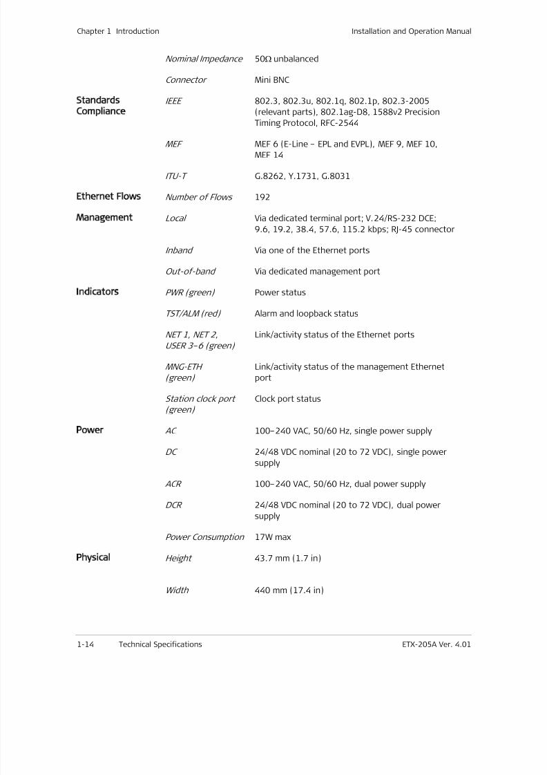
7/25/2019 Manual ETX-205A
http://slidepdf.com/reader/full/manual-etx-205a 50/409

7/25/2019 Manual ETX-205A
http://slidepdf.com/reader/full/manual-etx-205a 51/409
Installation and Operation Manual Chapter 1 Introduction
ETX-205A Ver. 4.01 Technical Specifications 1-15
Depth 240 mm (9.5 in)
Weight 3.1 kg (6.8 lb)
Environment Temperature Regular: 0 to 50°C (32 to 122°F)
Temperature-hardened: -20 to 65°C (-4 to 149°F
Humidity Up to 90%, non-condensing

7/25/2019 Manual ETX-205A
http://slidepdf.com/reader/full/manual-etx-205a 52/409
Chapter 1 Introduction Installation and Operation Manual
1-16 Technical Specifications ETX-205A Ver. 4.01
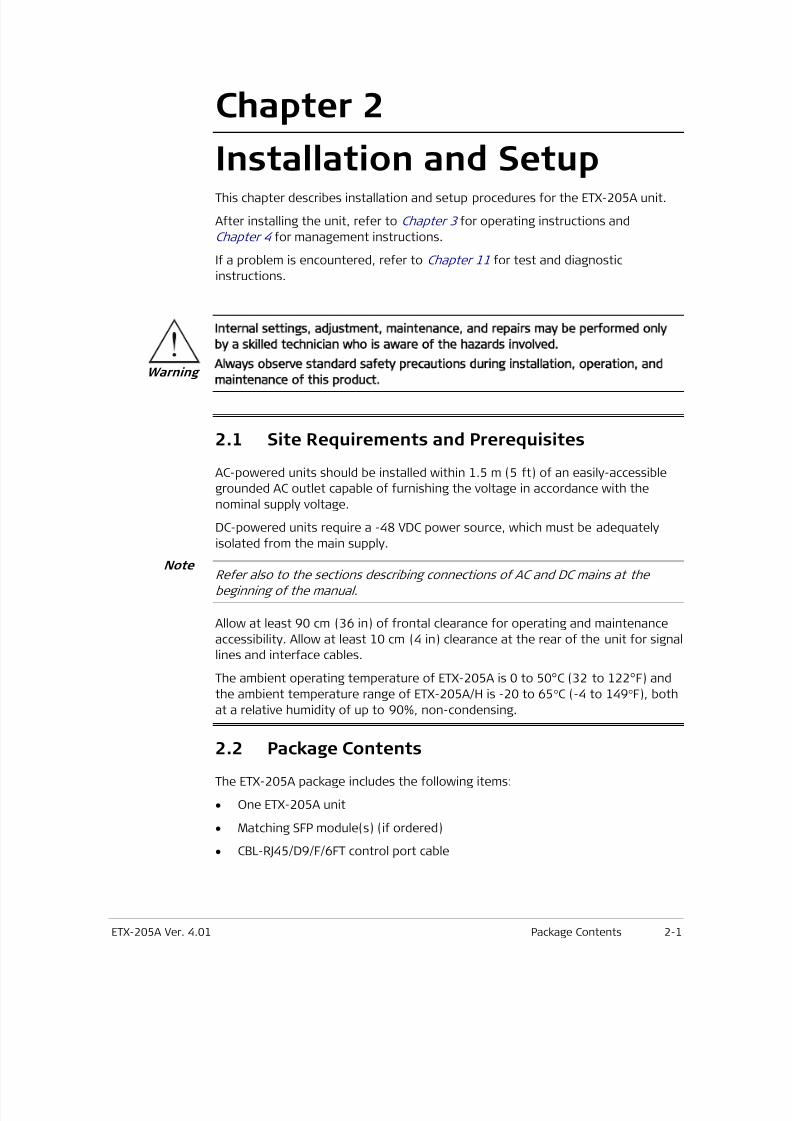
7/25/2019 Manual ETX-205A
http://slidepdf.com/reader/full/manual-etx-205a 53/409
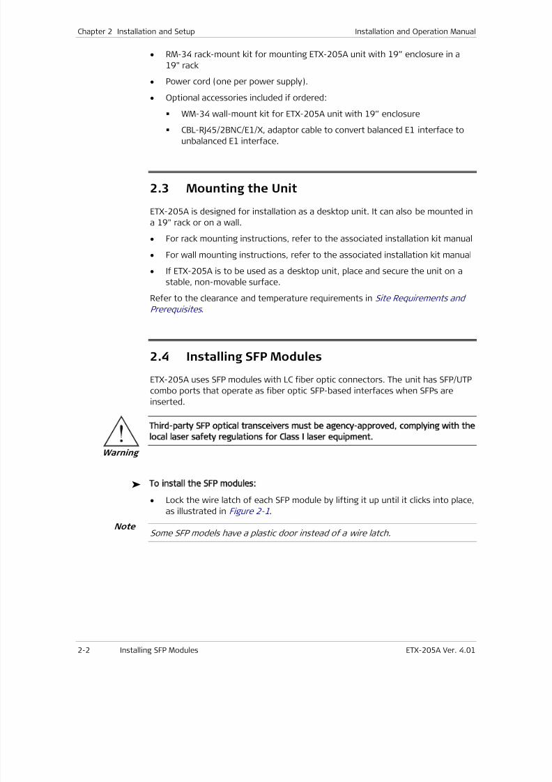
7/25/2019 Manual ETX-205A
http://slidepdf.com/reader/full/manual-etx-205a 54/409
Chapter 2 Installation and Setup Installation and Operation Manual
2-2 Installing SFP Modules ETX-205A Ver. 4.01
• RM-34 rack-mount kit for mounting ETX-205A unit with 19” enclosure in a
19" rack
• Power cord (one per power supply).
• Optional accessories included if ordered:
WM-34 wall-mount kit for ETX-205A unit with 19” enclosure
CBL-RJ45/2BNC/E1/X, adaptor cable to convert balanced E1 interface tounbalanced E1 interface.
2.3 Mounting the Unit
ETX-205A is designed for installation as a desktop unit. It can also be mounted in
a 19" rack or on a wall.
• For rack mounting instructions, refer to the associated installation kit manual
• For wall mounting instructions, refer to the associated installation kit manual
• If ETX-205A is to be used as a desktop unit, place and secure the unit on a
stable, non-movable surface.
Refer to the clearance and temperature requirements in Site Requirements and
Prerequisites .
2.4 Installing SFP Modules
ETX-205A uses SFP modules with LC fiber optic connectors. The unit has SFP/UTP
combo ports that operate as fiber optic SFP-based interfaces when SFPs areinserted.
Third-party SFP optical transceivers must be agency-approved, complying with the
local laser safety regulations for Class I laser equipment.
To install the SFP modules:
• Lock the wire latch of each SFP module by lifting it up until it clicks into place,
as illustrated in Figure 2-1.
Some SFP models have a plastic door instead of a wire latch.Note
Warning
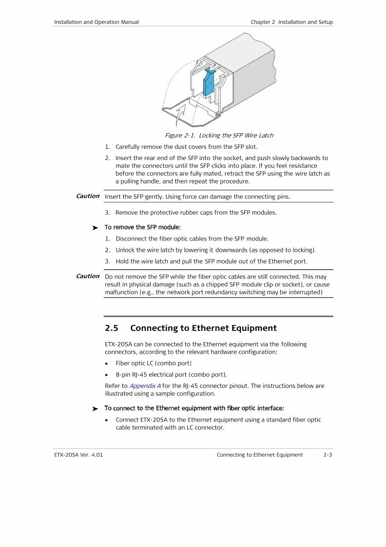
7/25/2019 Manual ETX-205A
http://slidepdf.com/reader/full/manual-etx-205a 55/409
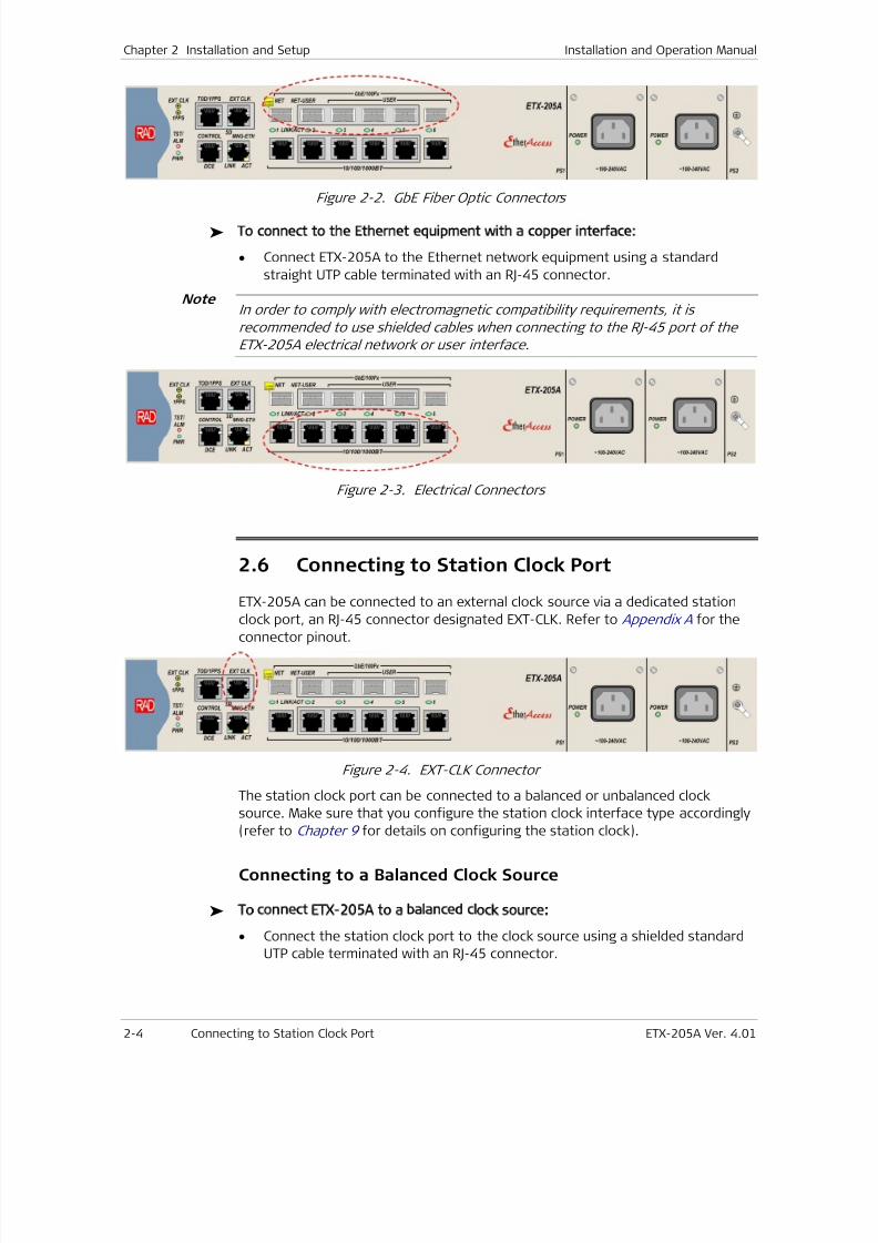
7/25/2019 Manual ETX-205A
http://slidepdf.com/reader/full/manual-etx-205a 56/409
Chapter 2 Installation and Setup Installation and Operation Manual
2-4 Connecting to Station Clock Port ETX-205A Ver. 4.01
Figure 2-2. GbE Fiber Optic Connectors
To connect to the Ethernet equipment with a copper interface:
• Connect ETX-205A to the Ethernet network equipment using a standard
straight UTP cable terminated with an RJ-45 connector.
In order to comply with electromagnetic compatibility requirements, it is
recommended to use shielded cables when connecting to the RJ-45 port of the
ETX-205A electrical network or user interface.
Figure 2-3. Electrical Connectors
2.6
Connecting to Station Clock Port
ETX-205A can be connected to an external clock source via a dedicated station
clock port, an RJ-45 connector designated EXT-CLK. Refer to Appendix A for theconnector pinout.
Figure 2-4. EXT-CLK Connector
The station clock port can be connected to a balanced or unbalanced clock
source. Make sure that you configure the station clock interface type accordingly
(refer to Chapter 9 for details on configuring the station clock).
Connecting to a Balanced Clock Source
To connect ETX-205A to a balanced clock source:
• Connect the station clock port to the clock source using a shielded standard
UTP cable terminated with an RJ-45 connector.
Note
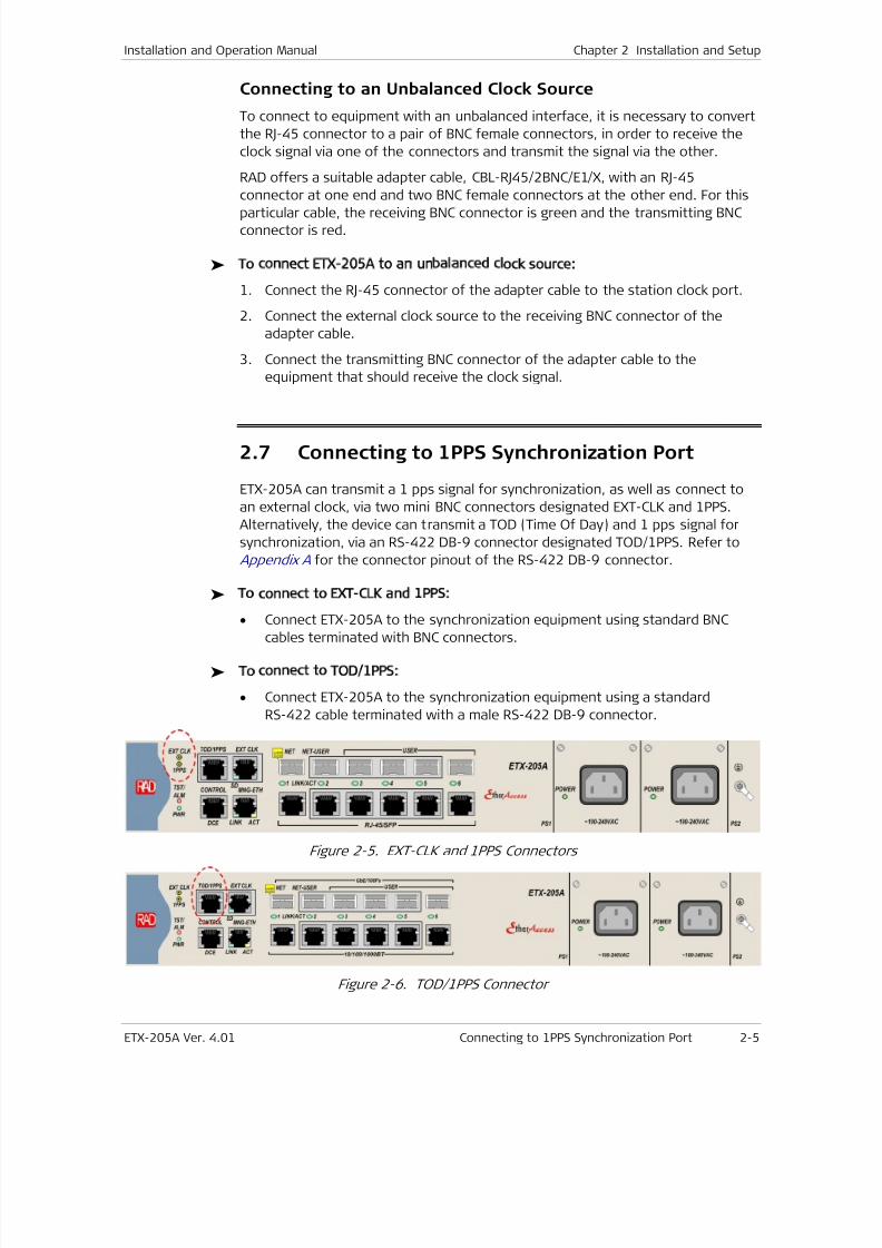
7/25/2019 Manual ETX-205A
http://slidepdf.com/reader/full/manual-etx-205a 57/409
Installation and Operation Manual Chapter 2 Installation and Setup
ETX-205A Ver. 4.01 Connecting to 1PPS Synchronization Port 2-5
Connecting to an Unbalanced Clock Source
To connect to equipment with an unbalanced interface, it is necessary to convert
the RJ-45 connector to a pair of BNC female connectors, in order to receive the
clock signal via one of the connectors and transmit the signal via the other.
RAD offers a suitable adapter cable, CBL-RJ45/2BNC/E1/X, with an RJ-45
connector at one end and two BNC female connectors at the other end. For this
particular cable, the receiving BNC connector is green and the transmitting BNCconnector is red.
To connect ETX-205A to an unbalanced clock source:
1. Connect the RJ-45 connector of the adapter cable to the station clock port.
2. Connect the external clock source to the receiving BNC connector of the
adapter cable.
3. Connect the transmitting BNC connector of the adapter cable to the
equipment that should receive the clock signal.
2.7 Connecting to 1PPS Synchronization Port
ETX-205A can transmit a 1 pps signal for synchronization, as well as connect to
an external clock, via two mini BNC connectors designated EXT-CLK and 1PPS.
Alternatively, the device can transmit a TOD (Time Of Day) and 1 pps signal for
synchronization, via an RS-422 DB-9 connector designated TOD/1PPS. Refer to
Appendix A for the connector pinout of the RS-422 DB-9 connector.
To connect to EXT-CLK and 1PPS:
•
Connect ETX-205A to the synchronization equipment using standard BNCcables terminated with BNC connectors.
To connect to TOD/1PPS:
• Connect ETX-205A to the synchronization equipment using a standard
RS-422 cable terminated with a male RS-422 DB-9 connector.
Figure 2-5. EXT-CLK and 1PPS Connectors
Figure 2-6. TOD/1PPS Connector
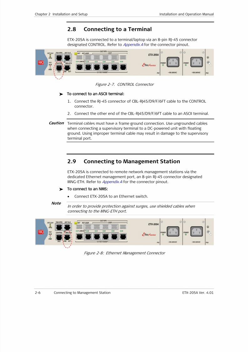
7/25/2019 Manual ETX-205A
http://slidepdf.com/reader/full/manual-etx-205a 58/409
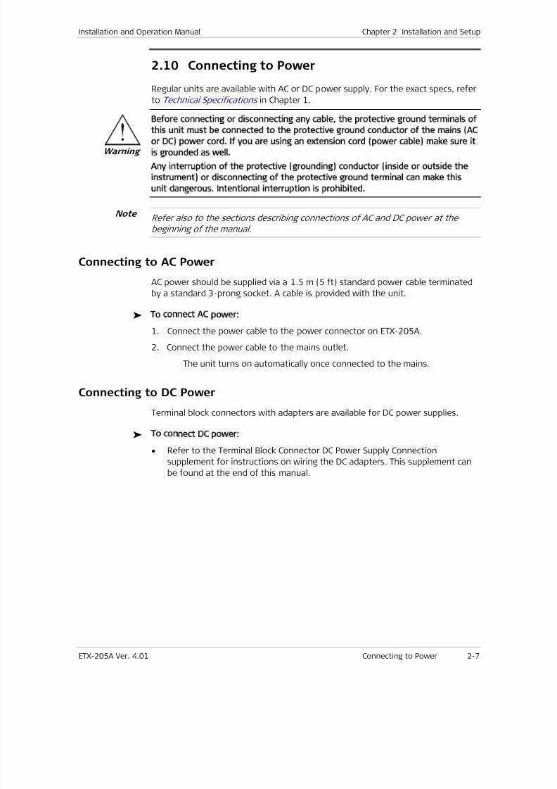
7/25/2019 Manual ETX-205A
http://slidepdf.com/reader/full/manual-etx-205a 59/409
Installation and Operation Manual Chapter 2 Installation and Setup
ETX-205A Ver. 4.01 Connecting to Power 2-7
2.10
Connecting to Power
Regular units are available with AC or DC power supply. For the exact specs, refer
to Technical Specifications in Chapter 1.
Before connecting or disconnecting any cable, the protective ground terminals of
this unit must be connected to the protective ground conductor of the mains AC
or DC) power cord. If you are using an extension cord power cable) make sure it
is grounded as well.
Any interruption of the protective grounding) conductor inside or outside the
instrument) or disconnecting of the protective ground terminal can make this
unit dangerous. Intentional interruption is prohibited.
Refer also to the sections describing connections of AC and DC power at the
beginning of the manual.
Connecting to AC Power
AC power should be supplied via a 1.5 m (5 ft) standard power cable terminated
by a standard 3-prong socket. A cable is provided with the unit.
To connect AC power:
1. Connect the power cable to the power connector on ETX-205A.
2. Connect the power cable to the mains outlet.
The unit turns on automatically once connected to the mains.
Connecting to DC Power
Terminal block connectors with adapters are available for DC power supplies.
To connect DC power:
• Refer to the Terminal Block Connector DC Power Supply Connection
supplement for instructions on wiring the DC adapters. This supplement can
be found at the end of this manual.
Warning
Note

7/25/2019 Manual ETX-205A
http://slidepdf.com/reader/full/manual-etx-205a 60/409
7/25/2019 Manual ETX-205A
http://slidepdf.com/reader/full/manual-etx-205a 61/409
ETX-205A Ver. 4.01 Turning On the Unit 3-1
Chapter 3
OperationThis chapter:
• Explains power-on and power-off procedures
• Provides a detailed description of the front panel controls and indicators and
their functions.
For a detailed explanation of parameters, refer to Chapters 6 –10 .
3.1
Turning On the Unit
To turn on ETX 205A:
• Connect the power cord to the mains.
The PWR indicator lights up and remains lit as long as ETX-205A receives
power.
ETX-205A requires no operator attention once installed, with the exception of
occasional monitoring of front panel indicators. Intervention is only required
when ETX-205A must be configured to its operational requirements, or diagnostic
tests are performed.
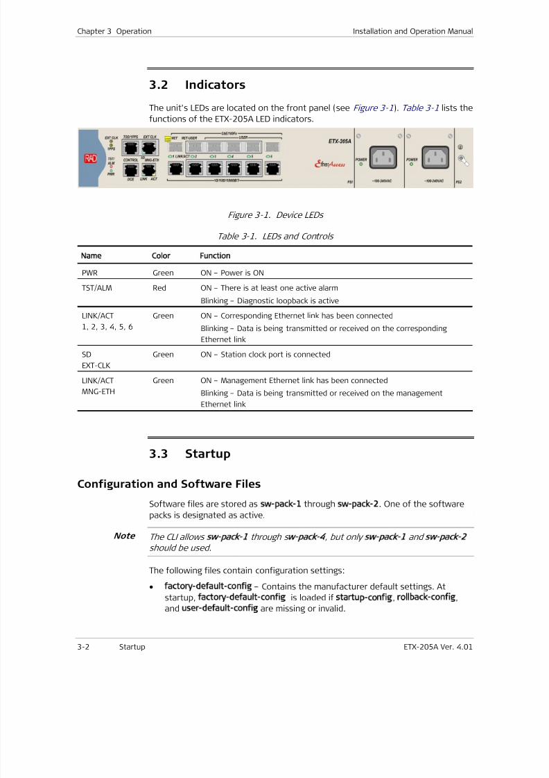
7/25/2019 Manual ETX-205A
http://slidepdf.com/reader/full/manual-etx-205a 62/409
Chapter 3 Operation Installation and Operation Manual
3-2 Startup ETX-205A Ver. 4.01
3.2
Indicators
The unit's LEDs are located on the front panel (see Figure 3-1). Table 3-1 lists the
functions of the ETX-205A LED indicators.
Figure 3-1. Device LEDs
Table 3-1. LEDs and Controls
Name Color Function
PWR Green ON – Power is ON
TST/ALM Red ON – There is at least one active alarm
Blinking – Diagnostic loopback is active
LINK/ACT
1, 2, 3, 4, 5, 6
Green ON – Corresponding Ethernet link has been connected
Blinking – Data is being transmitted or received on the corresponding
Ethernet link
SD
EXT-CLK
Green ON – Station clock port is connected
LINK/ACT
MNG-ETH
Green ON – Management Ethernet link has been connected
Blinking – Data is being transmitted or received on the management
Ethernet link
3.3
Startup
Configuration and Software Files
Software files are stored as sw pack 1 through sw pack 2. One of the software
packs is designated as active.
The CLI allows sw pack 1 through s w pack 4, but only sw pack 1 and sw pack 2
should be used.
The following files contain configuration settings:
• factory default config – Contains the manufacturer default settings. At
startup, factory default config is loaded if startup config, rollback config,
and user default config are missing or invalid.
Note
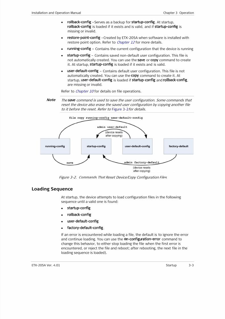
7/25/2019 Manual ETX-205A
http://slidepdf.com/reader/full/manual-etx-205a 63/409
Installation and Operation Manual Chapter 3 Operation
ETX-205A Ver. 4.01 Startup 3-3
• rollback config –Serves as a backup for startup config. At startup,
rollback config is loaded if it exists and is valid, and if startup config is
missing or invalid.
• restore point config –Created by ETX-205A when software is installed with
restore point option. Refer to Chapter 12 for more details.
• running config – Contains the current configuration that the device is running
• startup config – Contains saved non-default user configuration. This file is
not automatically created. You can use the save or copy command to create
it. At startup, startup config is loaded if it exists and is valid.
• user default config – Contains default user configuration. This file is not
automatically created. You can use the copy command to create it. At
startup, user default config is loaded if startup config and rollback config,
are missing or invalid.
Refer to Chapter 10 for details on file operations.
The save command is used to save the user configuration. Some commands that
reset the device also erase the saved user configuration by copying another fileto it before the reset. Refer to Figure 3-2f or details.
Figure 3-2. Commands That Reset Device/Copy Configuration Files
Loading Sequence
At startup, the device attempts to load configuration files in the following
sequence until a valid one is found:
• startup config
• rollback config
• user default config
• factory default config.
If an error is encountered while loading a file, the default is to ignore the error
and continue loading. You can use the on configuration error command to
change this behavior, to either stop loading the file when the first error is
encountered, or reject the file and reboot; after rebooting, the next file in the
loading sequence is loaded).
Note
7/25/2019 Manual ETX-205A
http://slidepdf.com/reader/full/manual-etx-205a 64/409
Chapter 3 Operation Installation and Operation Manual
3-4 Zero Touch Configuration ETX-205A Ver. 4.01
To display the parameter values after startup, use the info [detail]
command.
3.4 Using a Custom Configuration File
In large deployments, often a central network administrator sends configuration
scripts to the remote locations and all that remains for the local technician to do
is to replace the IP address in the script or other similar minor changes, and then
download the file to the device. Alternatively, the technician can download the
file as is to the device, log in to the device and make the required changes, then
save the configuration.
To download the configuration file, use the copy command (refer to Chapter 10 ).
After downloading the configuration file, the unit must be reset in order to
execute the file. After the unit completes its startup, the custom configuration is
complete.
You can use the zero touch feature to distribute software and configuration filesautomatically to units. Refer to Zero Touch Configuration for details.
3.5
Zero Touch Configuration
The Zero Touch feature allows ETX-205A to receive software and configuration
files via a DHCP server and TFTP server, eliminating the need to manually log into
ETX-205A in order to transfer the required files to it.
Prerequisites• A Zero Touch configuration (ZTC) XML file, containing directives for the
software and configuration files. To prepare this file, refer to ZTC File
Structure .
• A DHCP server for providing the TFTP server address, in addition to the usual
IP address, default gateway, etc.
• A TFTP server from which to download the following:
ZTC file
Software image file, if required by the directives
Configuration file, if required by the directives.
Sequence
1. At reboot, when ETX-205A obtains a DHCP lease from the DHCP server, the
lease provides the TFTP server address, either via option 150, or as a string
(‘xxx.xxx.xxx.xxx’) via option 66. Optionally, the DHCP lease provides the path
and/or the file name of the ZTC file via DHCP option 67.
7/25/2019 Manual ETX-205A
http://slidepdf.com/reader/full/manual-etx-205a 65/409
Installation and Operation Manual Chapter 3 Operation
ETX-205A Ver. 4.01 Zero Touch Configuration 3-5
2. ETX-205A loads the ZTC file from the TFTP server, according to the
information received in the lease. If not specified in the lease, the default
path is rad/, and the default file name is rad.xml. After the ZTC file is loaded,
it is saved in the file system as zero touch config xml.
3. If zero touch config xml contains directives for a software file, ETX-205A
does one of the following, according to the action specified in the directives:
Upgrade only – Load software file if it is newer than the active softwareimage
Downgrade only – Load software file if it is older than the active software
image
Replace – Load software file if different from the active software image.
4. If zero touch config xml contains directives for a configuration file, then if
the action specified in the directives is Replace, ETX-205A loads the specified
configuration file if it is different than the last configuration file loaded via
the ZTC mechanism, and saves it as startup config.
5. If a software file was downloaded, ETX-205A installs it as the active software
pack.
6. If a software file and/or configuration file was downloaded, ETX-205A
reboots. After startup, the sequence described in Loading Sequence is
performed.
7. If no reboot was needed, ETX-205A performs the sequence described in
Loading Sequence .
If an error occurs in the ZTC process, ETX-205A starts a 10-minute timer and then
performs the sequence described in Loading Sequence . When the timer expires,
ETX-205A again attempts the ZTC process.
ZTC File Structure
This section describes the ZTC directives in the ZTC file, which is written in
standard XML, based on the Netconf schema. The file can contain directives for
one or more devices. This flexibility enables the use of one ZTC file per device, or
one ZTC file for all devices. ZTC File Example shows a ZTC file containing directives
for ETX-203AX, ETX-205A, and ETX-220A.
The directives are enclosed in the element pair <zero touch configuration>
</zero touch configuration>. The ZTC directives for a particular device are
enclosed by an element pair such as <ETX 205A> </ETX 205A>. The element
contents are according to the chassis name displayed in the output of show
inventory table (refer to Chapter 10 ). The file can contain software-relateddirectives and/or configuration-related directives for each device.
Software Directives
The following directives supply information about the software file to download:
• sw version –Version of the software to download; must be formatted in the
same way as the chassis software revision displayed in the output of show
inventory table (refer to Chapter 10 ).
7/25/2019 Manual ETX-205A
http://slidepdf.com/reader/full/manual-etx-205a 66/409

7/25/2019 Manual ETX-205A
http://slidepdf.com/reader/full/manual-etx-205a 67/409
Installation and Operation Manual Chapter 3 Operation
ETX-205A Ver. 4.01 Zero Touch Configuration 3-7
• ETX-205A:
If version 4.01.50 is newer than the active software version, download
/rad/etx/etx205A.sw and save it as specified for the auto option in
Software Directives .
If the last downloaded ZTC configuration version was not
etx205A 4.01.50, download /rad/etx/etx205A.cfg and save it as
startup config.
• ETX-220A:
If version 4.01.10 is newer than the active software version, download
/rad/etx/etx220A.sw and save it as specified for the auto option in
Software Directives .
If the last downloaded ZTC configuration version was not
etx220A 4.01.10, download /rad/etx/etx220A.cfg and save it as
startup config.
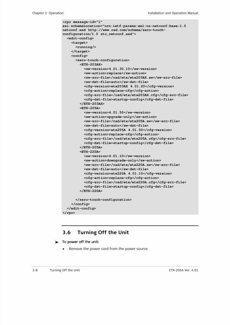
7/25/2019 Manual ETX-205A
http://slidepdf.com/reader/full/manual-etx-205a 68/409
Chapter 3 Operation Installation and Operation Manual
3-8 Turning Off the Unit ETX-205A Ver. 4.01
<rpc message-id="1"
xsi:schemaLocation="urn:ietf:params:xml:ns:netconf:base:1.0netconf.xsd http://www.rad.com/schema/zero-touch-
configuration/1.0 ztc_netconf.xsd">
<edit-config>
<target>
<running/>
</target>
<config>
<zero-touch-configuration>
<ETX-203AX>
<sw-version>4.01.30.10</sw-version>
<sw-action>replace</sw-action>
<sw-src-file>/rad/etx/etx203AX.sw</sw-src-file>
<sw-dst-file>auto</sw-dst-file>
<cfg-version>etx203AX 4.01.20</cfg-version>
<cfg-action>replace-cfg</cfg-action>
<cfg-src-file>/rad/etx/etx203AX.cfg</cfg-src-file>
<cfg-dst-file>startup-config</cfg-dst-file>
</ETX-203AX>
<ETX-205A><sw-version>4.01.50</sw-version>
<sw-action>upgrade-only</sw-action>
<sw-src-file>/rad/etx/etx205A.sw</sw-src-file>
<sw-dst-file>auto</sw-dst-file>
<cfg-version>etx205A 4.01.50</cfg-version>
<cfg-action>replace-cfg</cfg-action>
<cfg-src-file>/rad/etx/etx205A.cfg</cfg-src-file>
<cfg-dst-file>startup-config</cfg-dst-file>
</ETX-205A>
<ETX-220A>
<sw-version>4.01.10</sw-version>
<sw-action>downgrade-only</sw-action><sw-src-file>/rad/etx/etx220A.sw</sw-src-file>
<sw-dst-file>auto</sw-dst-file>
<cfg-version>etx220A 4.01.10</cfg-version>
<cfg-action>replace-cfg</cfg-action>
<cfg-src-file>/rad/etx/etx220A.cfg</cfg-src-file>
<cfg-dst-file>startup-config</cfg-dst-file>
</ETX-220A>
</zero-touch-configuration>
</config>
</edit-config>
</rpc>
3.6 Turning Off the Unit
To power off the unit:
• Remove the power cord from the power source.
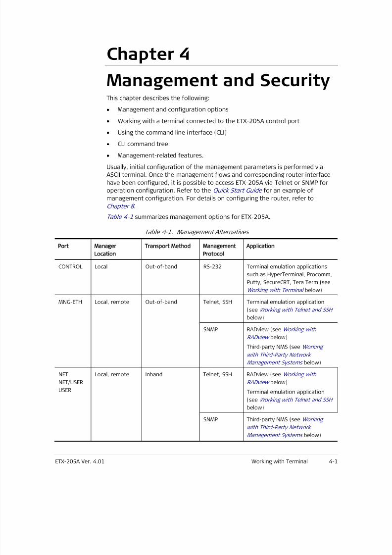
7/25/2019 Manual ETX-205A
http://slidepdf.com/reader/full/manual-etx-205a 69/409
ETX-205A Ver. 4.01 Working with Terminal 4-1
Chapter 4
Management and SecurityThis chapter describes the following:
• Management and configuration options
• Working with a terminal connected to the ETX-205A control port
• Using the command line interface (CLI)
• CLI command tree
• Management-related features.
Usually, initial configuration of the management parameters is performed via
ASCII terminal. Once the management flows and corresponding router interface
have been configured, it is possible to access ETX-205A via Telnet or SNMP foroperation configuration. Refer to the Quick Start Guide for an example of
management configuration. For details on configuring the router, refer to
Chapter 8 .
Table 4-1 summarizes management options for ETX-205A.
Table 4-1. Management Alternatives
Port Manager
Location
Transport Method Management
Protocol
Application
CONTROL Local Out-of-band RS-232 Terminal emulation applications
such as HyperTerminal, Procomm,Putty, SecureCRT, Tera Term (see
Working with Terminal below)
MNG-ETH Local, remote Out-of-band Telnet, SSH Terminal emulation application
(see Working with Telnet and SSH
below)
SNMP RADview (see Working with
RADview below)
Third-party NMS (see Working
with Third-Party Network
Management Systems below)
NET
NET/USER
USER
Local, remote Inband Telnet, SSH RADview (see Working with
RADview below)
Terminal emulation application
(see Working with Telnet and SSH
below)
SNMP Third-party NMS (see Working
with Third-Party Network
Management Systems below)
7/25/2019 Manual ETX-205A
http://slidepdf.com/reader/full/manual-etx-205a 70/409
Chapter 4 Management and Security Installation and Operation Manual
4-2 Working with Terminal ETX-205A Ver. 4.01
By default, the terminal, Telnet (SSH), and SNMP management access methods
are enabled. Refer to Controlling Management Access for details on
enabling/disabling a particular method.
4.1 Working with Terminal
ETX-205A has a V.24/RS-232 asynchronous DCE port, designated CONTROL and
terminated in an RJ-45 connector. The control port continuously monitors the
incoming data stream and immediately responds to any input string received
through this port. You can use any terminal emulation program to manage
ETX-205A via the control port; the following procedure uses HyperTerminal.
To start a terminal control session:
1. Make sure all ETX-205A cables and connectors are properly connected.
2. Connect ETX-205A to a PC equipped with an ASCII terminal emulation
application (for example, HyperTerminal). Refer to Chapter 2 for details onconnecting to the control port.
3. Start the PC terminal emulation (in Windows XP: Select Start > All Programs >
Accessories > Communications> HyperTerminal to create a new terminal
connection).
The HyperTerminal application opens, and the Connection Description
dialog box is displayed.
Note
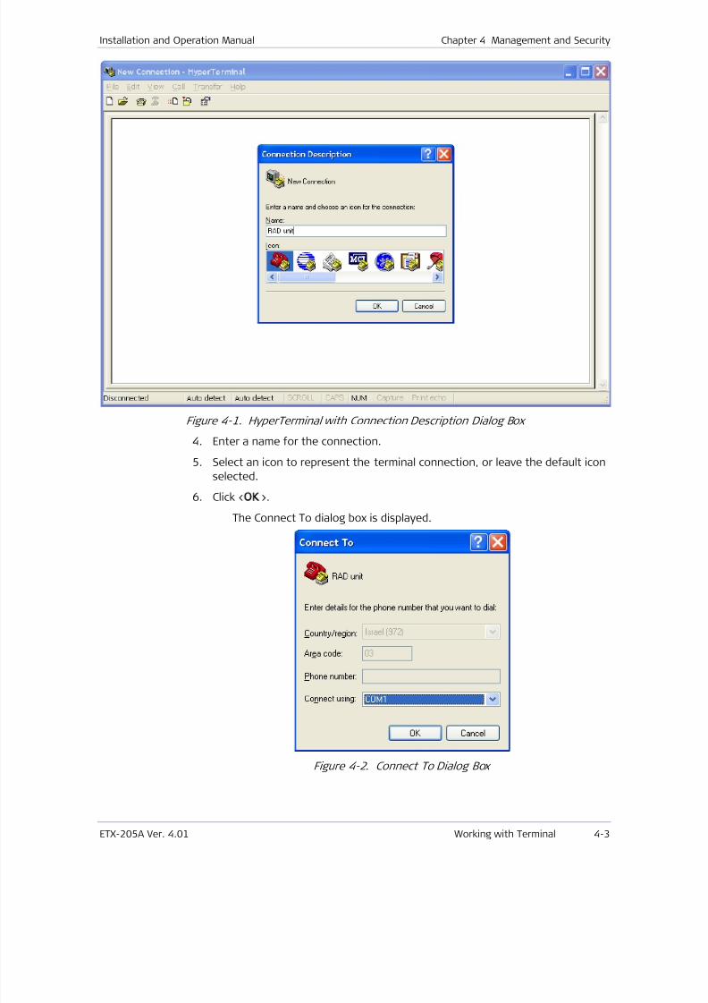
7/25/2019 Manual ETX-205A
http://slidepdf.com/reader/full/manual-etx-205a 71/409
Installation and Operation Manual Chapter 4 Management and Security
ETX-205A Ver. 4.01 Working with Terminal 4-3
Figure 4-1. HyperTerminal with Connection Description Dialog Box
4. Enter a name for the connection.
5. Select an icon to represent the terminal connection, or leave the default icon
selected.
6. Click <OK>.The Connect To dialog box is displayed.
Figure 4-2. Connect To Dialog Box
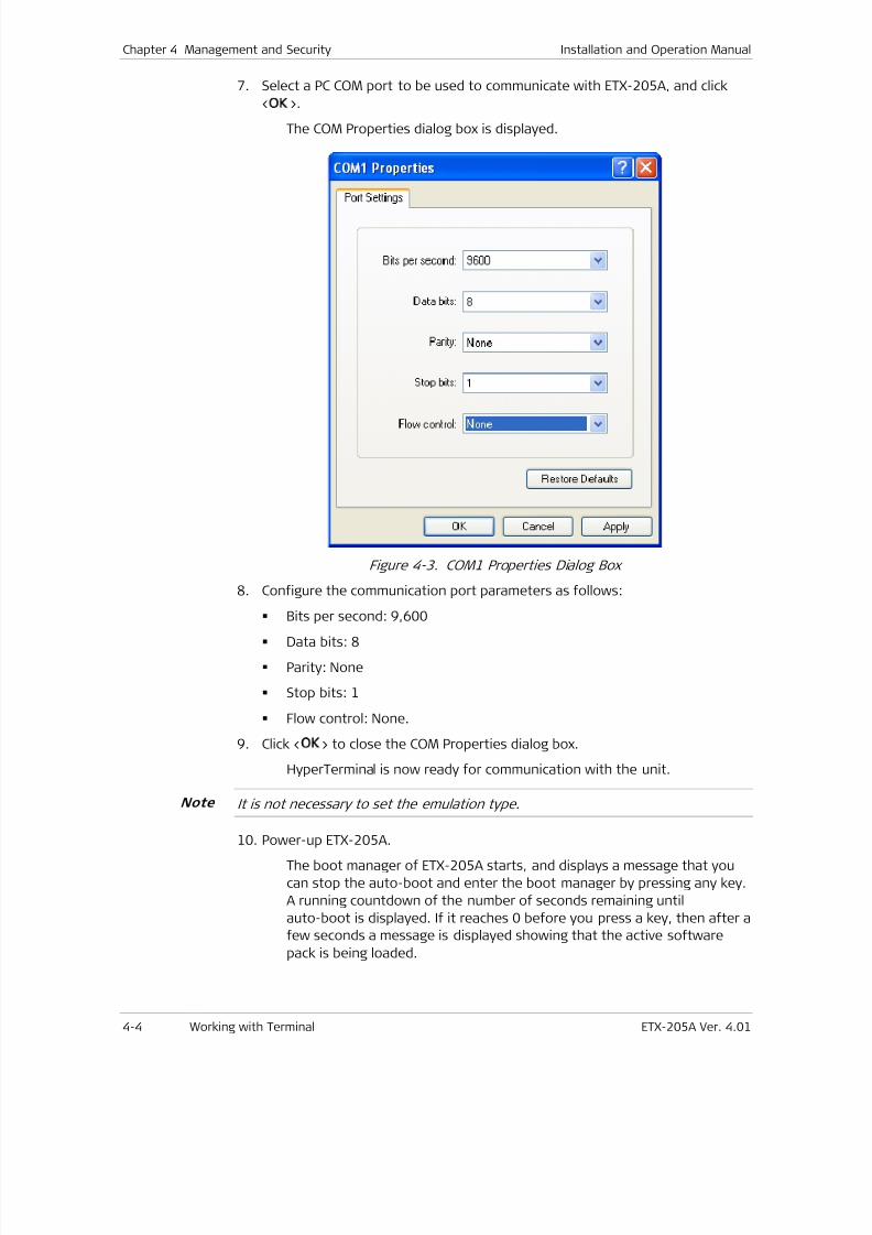
7/25/2019 Manual ETX-205A
http://slidepdf.com/reader/full/manual-etx-205a 72/409
Chapter 4 Management and Security Installation and Operation Manual
4-4 Working with Terminal ETX-205A Ver. 4.01
7. Select a PC COM port to be used to communicate with ETX-205A, and click
<OK>.
The COM Properties dialog box is displayed.
Figure 4-3. COM1 Properties Dialog Box
8. Configure the communication port parameters as follows:
Bits per second: 9,600
Data bits: 8
Parity: None
Stop bits: 1
Flow control: None.
9. Click <OK> to close the COM Properties dialog box.
HyperTerminal is now ready for communication with the unit.
It is not necessary to set the emulation type.
10. Power-up ETX-205A.
The boot manager of ETX-205A starts, and displays a message that you
can stop the auto-boot and enter the boot manager by pressing any key.
A running countdown of the number of seconds remaining until
auto-boot is displayed. If it reaches 0 before you press a key, then after a
few seconds a message is displayed showing that the active software
pack is being loaded.
Note
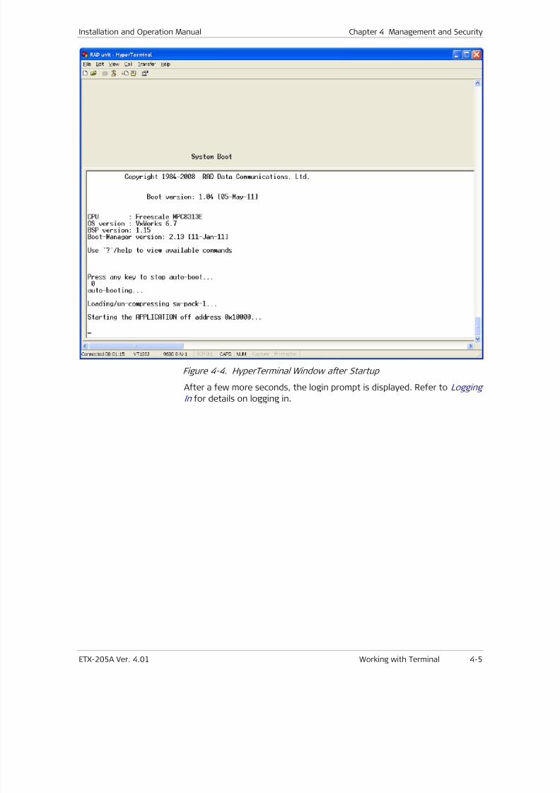
7/25/2019 Manual ETX-205A
http://slidepdf.com/reader/full/manual-etx-205a 73/409
Installation and Operation Manual Chapter 4 Management and Security
ETX-205A Ver. 4.01 Working with Terminal 4-5
Figure 4-4. HyperTerminal Window after Startup
After a few more seconds, the login prompt is displayed. Refer to Logging
In for details on logging in.
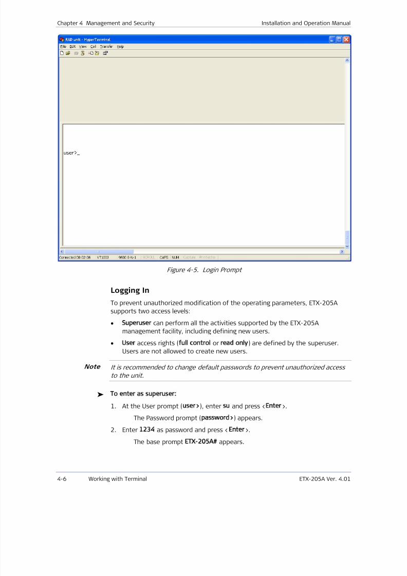
7/25/2019 Manual ETX-205A
http://slidepdf.com/reader/full/manual-etx-205a 74/409
Chapter 4 Management and Security Installation and Operation Manual
4-6 Working with Terminal ETX-205A Ver. 4.01
Figure 4-5. Login Prompt
Logging In
To prevent unauthorized modification of the operating parameters, ETX-205A
supports two access levels:
• Superuser can perform all the activities supported by the ETX-205A
management facility, including defining new users.
• User access rights (full control or read only) are defined by the superuser.
Users are not allowed to create new users.
It is recommended to change default passwords to prevent unauthorized access
to the unit.
To enter as superuser:
1. At the User prompt (user>), enter su and press <Enter>.
The Password prompt (password>) appears.
2. Enter 1234 as password and press <Enter>.
The base prompt ETX-205A appears.
Note
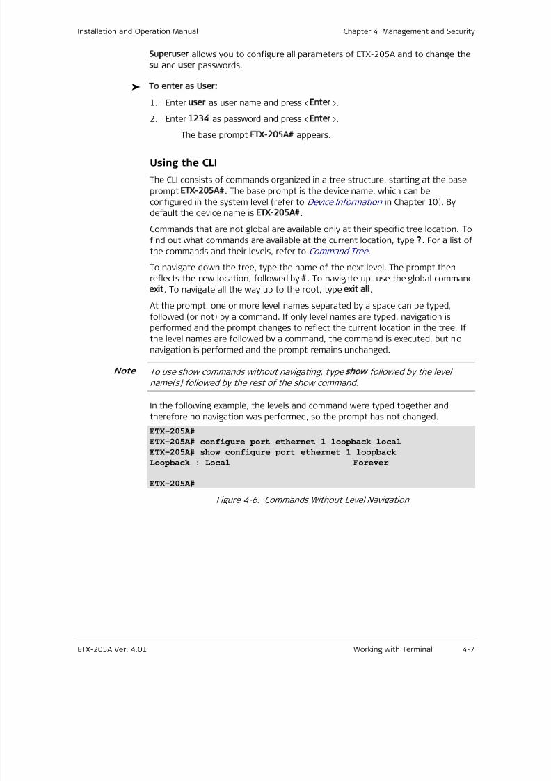
7/25/2019 Manual ETX-205A
http://slidepdf.com/reader/full/manual-etx-205a 75/409
Installation and Operation Manual Chapter 4 Management and Security
ETX-205A Ver. 4.01 Working with Terminal 4-7
Superuser allows you to configure all parameters of ETX-205A and to change the
su and user passwords.
To enter as User:
1. Enter user as user name and press <Enter>.
2. Enter 1234 as password and press <Enter>.
The base prompt ETX-205A appears.
Using the CLI
The CLI consists of commands organized in a tree structure, starting at the base
prompt ETX-205A . The base prompt is the device name, which can be
configured in the system level (refer to Device Information in Chapter 10). By
default the device name is ETX-205A .
Commands that are not global are available only at their specific tree location. To
find out what commands are available at the current location, type ?. For a list of
the commands and their levels, refer to Command Tree .
To navigate down the tree, type the name of the next level. The prompt then
reflects the new location, followed by . To navigate up, use the global command
exit. To navigate all the way up to the root, type exit all.
At the prompt, one or more level names separated by a space can be typed,
followed (or not) by a command. If only level names are typed, navigation is
performed and the prompt changes to reflect the current location in the tree. If
the level names are followed by a command, the command is executed, but no
navigation is performed and the prompt remains unchanged.
To use show commands without navigating, type show followed by the level
name(s) followed by the rest of the show command.
In the following example, the levels and command were typed together and
therefore no navigation was performed, so the prompt has not changed.
ETX-205A#
ETX-205A# configure port ethernet 1 loopback local
ETX-205A# show configure port ethernet 1 loopback
Loopback : Local Forever
ETX-205A#
Figure 4-6. Commands Without Level Navigation
Note
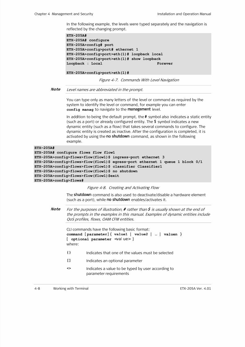
7/25/2019 Manual ETX-205A
http://slidepdf.com/reader/full/manual-etx-205a 76/409
Chapter 4 Management and Security Installation and Operation Manual
4-8 Working with Terminal ETX-205A Ver. 4.01
In the following example, the levels were typed separately and the navigation is
reflected by the changing prompt.
ETX-205A#
ETX-205A# configure
ETX-205A>config# port
ETX-205A>config>port# ethernet 1
ETX-205A>config>port>eth(1)# loopback local
ETX-205A>config>port>eth(1)# show loopbackLoopback : Local Forever
ETX-205A>config>port>eth(1)#
Figure 4-7. Commands With Level Navigation
Level names are abbreviated in the prompt.
You can type only as many letters of the level or command as required by the
system to identify the level or command, for example you can enterconfig manag to navigate to the management level.
In addition to being the default prompt, the symbol also indicates a static entity(such as a port) or already configured entity. The $ symbol indicates a new
dynamic entity (such as a flow) that takes several commands to configure. The
dynamic entity is created as inactive. After the configuration is completed, it is
activated by using the no shutdown command, as shown in the following
example.
ETX-205A#
ETX-205A# configure flows flow flow1
ETX-205A>config>flows>flow(flow1)$ ingress-port ethernet 3
ETX-205A>config>flows>flow(flow1)$ egress-port ethernet 1 queue 1 block 0/1
ETX-205A>config>flows>flow(flow1)$ classifier Classifier1
ETX-205A>config>flows>flow(flow1)$ no shutdown
ETX-205A>config>flows>flow(flow1)$exit
ETX-205A>config>flows#
Figure 4-8. Creating and Activating Flow
The shutdown command is also used to deactivate/disable a hardware element
(such as a port), while no shutdown enables/activates it.
For the purposes of illustration, rather than is usually shown at the end of
the prompts in the examples in this manual. Examples of dynamic entities include
QoS profiles, flows, OAM CFM entities.
CLI commands have the following basic format:command [ parameter] value1 | value2 | … | valuen
[ optional parameter <val ue> ]
where:
Indicates that one of the values must be selected
[] Indicates an optional parameter
<> Indicates a value to be typed by user according to
parameter requirements
Note
Note
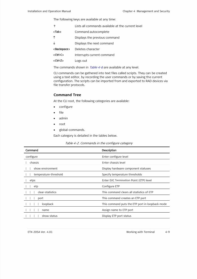
7/25/2019 Manual ETX-205A
http://slidepdf.com/reader/full/manual-etx-205a 77/409
Installation and Operation Manual Chapter 4 Management and Security
ETX-205A Ver. 4.01 Working with Terminal 4-9
The following keys are available at any time:
? Lists all commands available at the current level
<Tab> Command autocomplete
Displays the previous command
↓
Displays the next command
<Backspace> Deletes character
<Ctrl-C> Interrupts current command
<Ctrl-Z> Logs out
The commands shown in Table 4-6 are available at any level.
CLI commands can be gathered into text files called scripts. They can be created
using a text editor, by recording the user commands or by saving the current
configuration. The scripts can be imported from and exported to RAD devices via
file transfer protocols.
Command Tree
At the CLI root, the following categories are available:
• configure
• file
• admin
• root
• global-commands.
Each category is detailed in the tables below.
Table 4-2. Commands in the configure category
Command Description
configure Enter configure level
| chassis Enter chassis level
| | show environment Display hardware component statuses
| | temperature-threshold Specify temperature thresholds
| etps Enter EVC Termination Point (ETP) level
| | etp Configure ETP
| | | clear-statistics This command clears all statistics of ETP
| | | port This command creates an ETP port
| | | | loopback This command puts the ETP port in loopback mode
| | | | name Assign name to ETP port
| | | | show status Display ETP port status

7/25/2019 Manual ETX-205A
http://slidepdf.com/reader/full/manual-etx-205a 78/409
Chapter 4 Management and Security Installation and Operation Manual
4-10 Working with Terminal ETX-205A Ver. 4.01
Command Description
| | | | show loopback Display loopback status
| | | | shutdown Activate or deactivate ETP port
| | | protection Enter ETP protection level
| | | | aps-protocol Define APS protocol| | | | bind Bind transport port id
| | | | clear Clears the active near end lockout of Protection,
Forced Switch, Manual Switch, WTR state, or
Exercise command
| | | | force-switch Forces normal traffic signal to be selected from the
protection transport entity, meaning jump to next
port even if it is down
| | | | lockout This command prevents a working signal from
being selected from the protection transport
entity, effectively disabling the protection group
| | | | manual-switch In the absence of failure of working or protection
transport entity, forces normal traffic signal to be
selected from the protection transport entity,
meaning jump to next port only if it is not down
| | | | master-etp Configure master ETP
| | | | mode Configure protection mode
| | | | revertive Indicates if mode is revertive
| | | | sf-trigger Define signal failure trigger
| | | | wait-to-restore Define time between recovery and resumption oftransmission
| | | | show status Display protection status
| | | | shutdown Activate or deactivate ETP protection
| | | show status Display ETP status
| | | show statistics running Display ETP statistics
| | | show flows-summary Display flows corresponding to ETP
| fault Enter fault level
| | fault-propagation Configure fault propagation
| | | action-on-group Action(s) to perform in order to propagate a fault
| | | trigger Trigger for propagating fault
| | | wait-to-restore Define the time between recovery and resumption
of transmission
| | cfm Enter fault CFM level
| | | service Configure event reporting for service
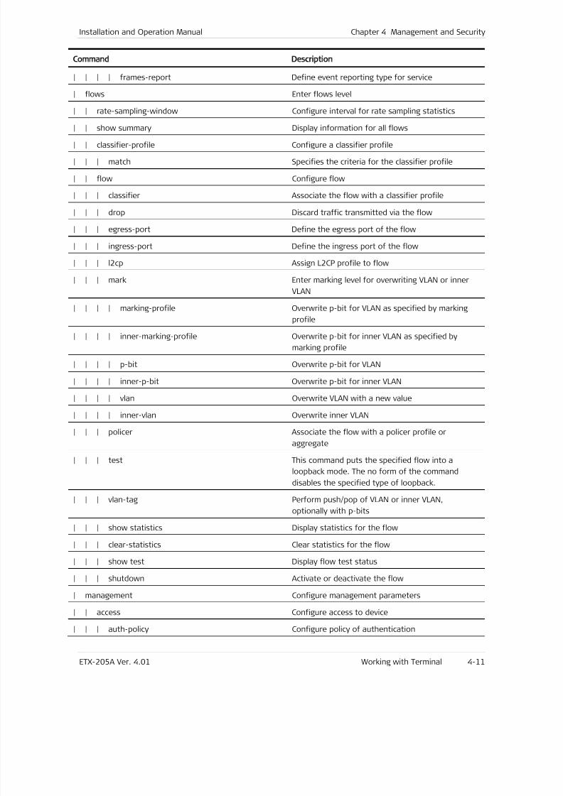
7/25/2019 Manual ETX-205A
http://slidepdf.com/reader/full/manual-etx-205a 79/409
Installation and Operation Manual Chapter 4 Management and Security
ETX-205A Ver. 4.01 Working with Terminal 4-11
Command Description
| | | | frames-report Define event reporting type for service
| flows Enter flows level
| | rate-sampling-window Configure interval for rate sampling statistics
| | show summary Display information for all flows| | classifier-profile Configure a classifier profile
| | | match Specifies the criteria for the classifier profile
| | flow Configure flow
| | | classifier Associate the flow with a classifier profile
| | | drop Discard traffic transmitted via the flow
| | | egress-port Define the egress port of the flow
| | | ingress-port Define the ingress port of the flow
| | | l2cp Assign L2CP profile to flow
| | | mark Enter marking level for overwriting VLAN or inner
VLAN
| | | | marking-profile Overwrite p-bit for VLAN as specified by marking
profile
| | | | inner-marking-profile Overwrite p-bit for inner VLAN as specified by
marking profile
| | | | p-bit Overwrite p-bit for VLAN
| | | | inner-p-bit Overwrite p-bit for inner VLAN
| | | | vlan Overwrite VLAN with a new value
| | | | inner-vlan Overwrite inner VLAN
| | | policer Associate the flow with a policer profile or
aggregate
| | | test This command puts the specified flow into a
loopback mode. The no form of the command
disables the specified type of loopback.
| | | vlan-tag Perform push/pop of VLAN or inner VLAN,
optionally with p-bits
| | | show statistics Display statistics for the flow
| | | clear-statistics Clear statistics for the flow
| | | show test Display flow test status
| | | shutdown Activate or deactivate the flow
| management Configure management parameters
| | access Configure access to device
| | | auth-policy Configure policy of authentication
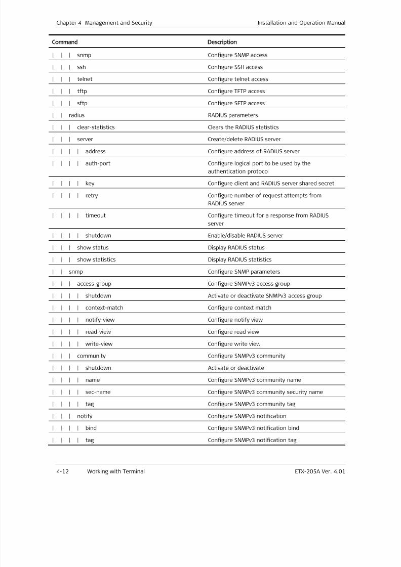
7/25/2019 Manual ETX-205A
http://slidepdf.com/reader/full/manual-etx-205a 80/409
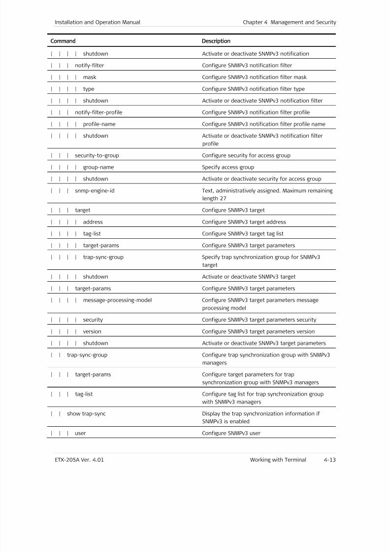
7/25/2019 Manual ETX-205A
http://slidepdf.com/reader/full/manual-etx-205a 81/409
Installation and Operation Manual Chapter 4 Management and Security
ETX-205A Ver. 4.01 Working with Terminal 4-13
Command Description
| | | | shutdown Activate or deactivate SNMPv3 notification
| | | notify-filter Configure SNMPv3 notification filter
| | | | mask Configure SNMPv3 notification filter mask
| | | | type Configure SNMPv3 notification filter type| | | | shutdown Activate or deactivate SNMPv3 notification filter
| | | notify-filter-profile Configure SNMPv3 notification filter profile
| | | | profile-name Configure SNMPv3 notification filter profile name
| | | | shutdown Activate or deactivate SNMPv3 notification filter
profile
| | | security-to-group Configure security for access group
| | | | group-name Specify access group
| | | | shutdown Activate or deactivate security for access group
| | | snmp-engine-id Text, administratively assigned. Maximum remaining
length 27
| | | target Configure SNMPv3 target
| | | | address Configure SNMPv3 target address
| | | | tag-list Configure SNMPv3 target tag list
| | | | target-params Configure SNMPv3 target parameters
| | | | trap-sync-group Specify trap synchronization group for SNMPv3
target
| | | | shutdown Activate or deactivate SNMPv3 target
| | | target-params Configure SNMPv3 target parameters
| | | | message-processing-model Configure SNMPv3 target parameters message
processing model
| | | | security Configure SNMPv3 target parameters security
| | | | version Configure SNMPv3 target parameters version
| | | | shutdown Activate or deactivate SNMPv3 target parameters
| | trap-sync-group Configure trap synchronization group with SNMPv3
managers
| | | target-params Configure target parameters for trap
synchronization group with SNMPv3 managers
| | | tag-list Configure tag list for trap synchronization group
with SNMPv3 managers
| | show trap-sync Display the trap synchronization information if
SNMPv3 is enabled
| | | user Configure SNMPv3 user
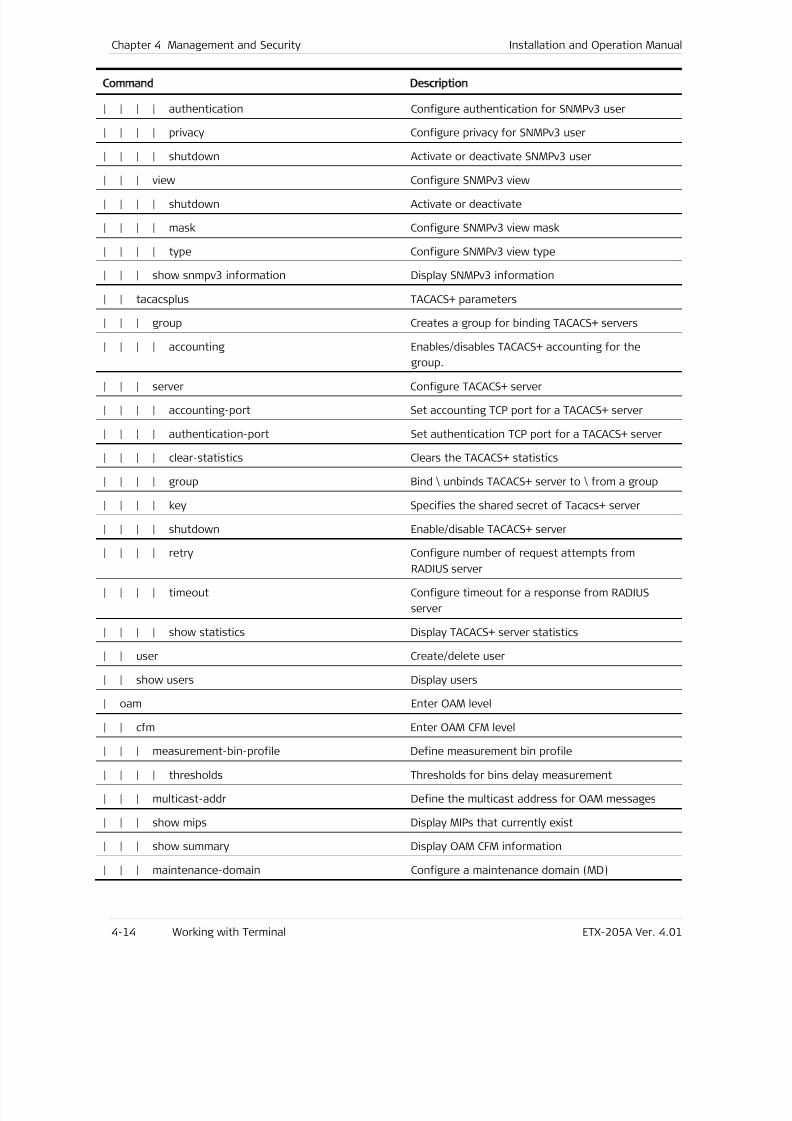
7/25/2019 Manual ETX-205A
http://slidepdf.com/reader/full/manual-etx-205a 82/409
Chapter 4 Management and Security Installation and Operation Manual
4-14 Working with Terminal ETX-205A Ver. 4.01
Command Description
| | | | authentication Configure authentication for SNMPv3 user
| | | | privacy Configure privacy for SNMPv3 user
| | | | shutdown Activate or deactivate SNMPv3 user
| | | view Configure SNMPv3 view| | | | shutdown Activate or deactivate
| | | | mask Configure SNMPv3 view mask
| | | | type Configure SNMPv3 view type
| | | show snmpv3 information Display SNMPv3 information
| | tacacsplus TACACS+ parameters
| | | group Creates a group for binding TACACS+ servers
| | | | accounting Enables/disables TACACS+ accounting for the
group.
| | | server Configure TACACS+ server
| | | | accounting-port Set accounting TCP port for a TACACS+ server
| | | | authentication-port Set authentication TCP port for a TACACS+ server
| | | | clear-statistics Clears the TACACS+ statistics
| | | | group Bind \ unbinds TACACS+ server to \ from a group
| | | | key Specifies the shared secret of Tacacs+ server
| | | | shutdown Enable/disable TACACS+ server
| | | | retry Configure number of request attempts from
RADIUS server
| | | | timeout Configure timeout for a response from RADIUS
server
| | | | show statistics Display TACACS+ server statistics
| | user Create/delete user
| | show users Display users
| oam Enter OAM level
| | cfm Enter OAM CFM level
| | | measurement-bin-profile Define measurement bin profile
| | | | thresholds Thresholds for bins delay measurement
| | | multicast-addr Define the multicast address for OAM messages
| | | show mips Display MIPs that currently exist
| | | show summary Display OAM CFM information
| | | maintenance-domain Configure a maintenance domain (MD)
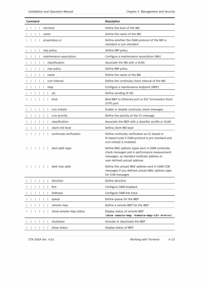
7/25/2019 Manual ETX-205A
http://slidepdf.com/reader/full/manual-etx-205a 83/409
Installation and Operation Manual Chapter 4 Management and Security
ETX-205A Ver. 4.01 Working with Terminal 4-15
Command Description
| | | | md-level Define the level of the MD
| | | | name Define the name of the MD
| | | | proprietary-cc Define whether the OAM protocol of the MD is
standard or pre-standard
| | | | mip-policy Define MIP policy
| | | | maintenance-association Configure a maintenance association (MA)
| | | | | classification Associate the MA with a VLAN
| | | | | mip-policy Define MIP policy
| | | | | name Define the name of the MA
| | | | | ccm-interval Define the continuity check interval of the MA
| | | | | mep Configure a maintenance endpoint (MEP)
| | | | | | ais Define sending of AIS
| | | | | | bind Bind MEP to Ethernet port or EVC Termination Point
(ETP) port
| | | | | | ccm-initiate Enable or disable continuity check messages
| | | | | | ccm-priority Define the priority of the CC message
| | | | | | classification Associate the MEP with a classifier profile or VLAN
| | | | | | client-md-level Define client MD level
| | | | | | continuity-verification Define continuity verification as CC-based or
lb-based (only if OAM protocol is pre-standard and
ccm-initiate is enabled)
| | | | | | dest-addr-type Define MAC address types sent in OAM continuity
check messages and in performance measurement
messages, as standard multicast address or
user-defined unicast address
| | | | | | dest-mac-addr Define the unicast MAC address sent in OAM CCM
messages if you defined unicast MAC address type
for CCM messages
| | | | | | direction Define direction
| | | | | | lbm Configure OAM loopback
| | | | | | linktrace Configure OAM link trace
| | | | | | queue Define queue for the MEP
| | | | | | remote-mep Define a remote MEP for the MEP
| | | | | | show remote-mep status Display status of remote MEP
(show remote-mep <remote-mep-id > status)
| | | | | | shutdown Activate or deactivate the MEP
| | | | | | show status Display status of MEP
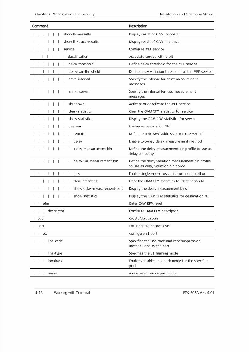
7/25/2019 Manual ETX-205A
http://slidepdf.com/reader/full/manual-etx-205a 84/409
Chapter 4 Management and Security Installation and Operation Manual
4-16 Working with Terminal ETX-205A Ver. 4.01
Command Description
| | | | | | show lbm-results Display result of OAM loopback
| | | | | | show linktrace-results Display result of OAM link trace
| | | | | | service Configure MEP service
| | | | | | classification Associate service with p-bit| | | | | | | delay-threshold Define delay threshold for the MEP service
| | | | | | | delay-var-threshold Define delay variation threshold for the MEP service
| | | | | | | dmm-interval Specify the interval for delay measurement
messages
| | | | | | | lmm-interval Specify the interval for loss measurement
messages
| | | | | | | shutdown Activate or deactivate the MEP service
| | | | | | | clear-statistics Clear the OAM CFM statistics for service
| | | | | | | show statistics Display the OAM CFM statistics for service
| | | | | | | dest-ne Configure destination NE
| | | | | | | | remote Define remote MAC address or remote MEP ID
| | | | | | | | delay Enable two-way delay measurement method
| | | | | | | | delay-measurement-bin Define the delay measurement bin profile to use as
delay bin policy
| | | | | | | | delay-var-measurement-bin Define the delay variation measurement bin profile
to use as delay variation bin policy
| | | | | | | | loss Enable single-ended loss measurement method
| | | | | | | | clear-statistics Clear the OAM CFM statistics for destination NE
| | | | | | | | show delay-measurement-bins Display the delay measurement bins
| | | | | | | | show statistics Display the OAM CFM statistics for destination NE
| | efm Enter OAM EFM level
| | | descriptor Configure OAM EFM descriptor
| peer Create/delete peer
| port Enter configure port level
| | e1 Configure E1 port
| | | line-code Specifies the line code and zero suppression
method used by the port
| | | line-type Specifies the E1 framing mode
| | | loopback Enables/disables loopback mode for the specified
port
| | | name Assigns/removes a port name
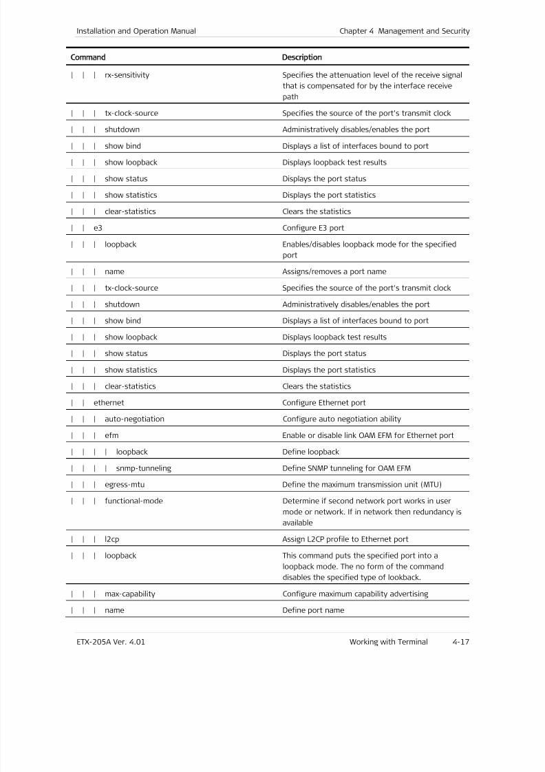
7/25/2019 Manual ETX-205A
http://slidepdf.com/reader/full/manual-etx-205a 85/409
Installation and Operation Manual Chapter 4 Management and Security
ETX-205A Ver. 4.01 Working with Terminal 4-17
Command Description
| | | rx-sensitivity Specifies the attenuation level of the receive signal
that is compensated for by the interface receive
path
| | | tx-clock-source Specifies the source of the port's transmit clock
| | | shutdown Administratively disables/enables the port
| | | show bind Displays a list of interfaces bound to port
| | | show loopback Displays loopback test results
| | | show status Displays the port status
| | | show statistics Displays the port statistics
| | | clear-statistics Clears the statistics
| | e3 Configure E3 port
| | | loopback Enables/disables loopback mode for the specified
port
| | | name Assigns/removes a port name
| | | tx-clock-source Specifies the source of the port's transmit clock
| | | shutdown Administratively disables/enables the port
| | | show bind Displays a list of interfaces bound to port
| | | show loopback Displays loopback test results
| | | show status Displays the port status
| | | show statistics Displays the port statistics
| | | clear-statistics Clears the statistics
| | ethernet Configure Ethernet port
| | | auto-negotiation Configure auto negotiation ability
| | | efm Enable or disable link OAM EFM for Ethernet port
| | | | loopback Define loopback
| | | | snmp-tunneling Define SNMP tunneling for OAM EFM
| | | egress-mtu Define the maximum transmission unit (MTU)
| | | functional-mode Determine if second network port works in user
mode or network. If in network then redundancy isavailable
| | | l2cp Assign L2CP profile to Ethernet port
| | | loopback This command puts the specified port into a
loopback mode. The no form of the command
disables the specified type of lookback.
| | | max-capability Configure maximum capability advertising
| | | name Define port name
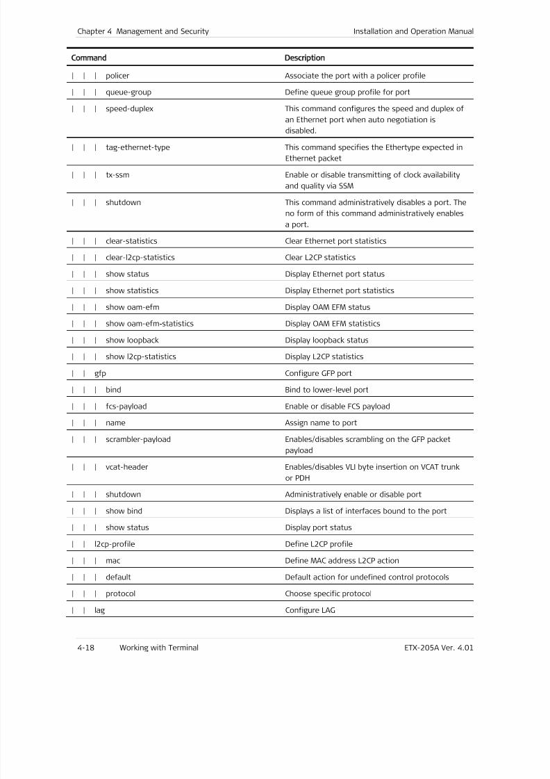
7/25/2019 Manual ETX-205A
http://slidepdf.com/reader/full/manual-etx-205a 86/409
Chapter 4 Management and Security Installation and Operation Manual
4-18 Working with Terminal ETX-205A Ver. 4.01
Command Description
| | | policer Associate the port with a policer profile
| | | queue-group Define queue group profile for port
| | | speed-duplex This command configures the speed and duplex of
an Ethernet port when auto negotiation is
disabled.
| | | tag-ethernet-type This command specifies the Ethertype expected in
Ethernet packet
| | | tx-ssm Enable or disable transmitting of clock availability
and quality via SSM
| | | shutdown This command administratively disables a port. The
no form of this command administratively enables
a port.
| | | clear-statistics Clear Ethernet port statistics
| | | clear-l2cp-statistics Clear L2CP statistics
| | | show status Display Ethernet port status
| | | show statistics Display Ethernet port statistics
| | | show oam-efm Display OAM EFM status
| | | show oam-efm-statistics Display OAM EFM statistics
| | | show loopback Display loopback status
| | | show l2cp-statistics Display L2CP statistics
| | gfp Configure GFP port
| | | bind Bind to lower-level port
| | | fcs-payload Enable or disable FCS payload
| | | name Assign name to port
| | | scrambler-payload Enables/disables scrambling on the GFP packet
payload
| | | vcat-header Enables/disables VLI byte insertion on VCAT trunk
or PDH
| | | shutdown Administratively enable or disable port
| | | show bind Displays a list of interfaces bound to the port
| | | show status Display port status
| | l2cp-profile Define L2CP profile
| | | mac Define MAC address L2CP action
| | | default Default action for undefined control protocols
| | | protocol Choose specific protocol
| | lag Configure LAG
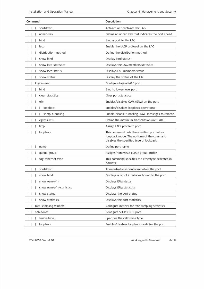
7/25/2019 Manual ETX-205A
http://slidepdf.com/reader/full/manual-etx-205a 87/409
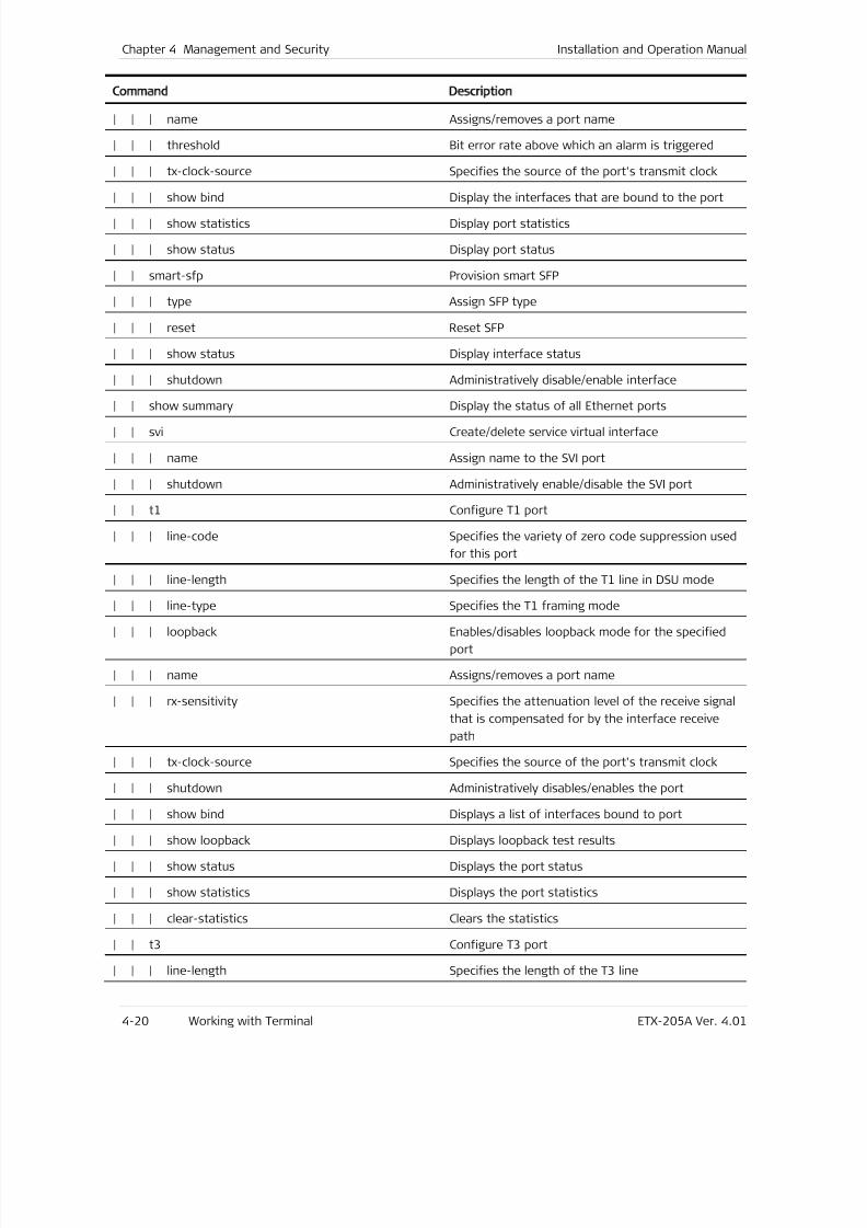
7/25/2019 Manual ETX-205A
http://slidepdf.com/reader/full/manual-etx-205a 88/409
Chapter 4 Management and Security Installation and Operation Manual
4-20 Working with Terminal ETX-205A Ver. 4.01
Command Description
| | | name Assigns/removes a port name
| | | threshold Bit error rate above which an alarm is triggered
| | | tx-clock-source Specifies the source of the port's transmit clock
| | | show bind Display the interfaces that are bound to the port| | | show statistics Display port statistics
| | | show status Display port status
| | smart-sfp Provision smart SFP
| | | type Assign SFP type
| | | reset Reset SFP
| | | show status Display interface status
| | | shutdown Administratively disable/enable interface
| | show summary Display the status of all Ethernet ports
| | svi Create/delete service virtual interface
| | | name Assign name to the SVI port
| | | shutdown Administratively enable/disable the SVI port
| | t1 Configure T1 port
| | | line-code Specifies the variety of zero code suppression used
for this port
| | | line-length Specifies the length of the T1 line in DSU mode
| | | line-type Specifies the T1 framing mode
| | | loopback Enables/disables loopback mode for the specified
port
| | | name Assigns/removes a port name
| | | rx-sensitivity Specifies the attenuation level of the receive signal
that is compensated for by the interface receive
path
| | | tx-clock-source Specifies the source of the port's transmit clock
| | | shutdown Administratively disables/enables the port
| | | show bind Displays a list of interfaces bound to port
| | | show loopback Displays loopback test results
| | | show status Displays the port status
| | | show statistics Displays the port statistics
| | | clear-statistics Clears the statistics
| | t3 Configure T3 port
| | | line-length Specifies the length of the T3 line
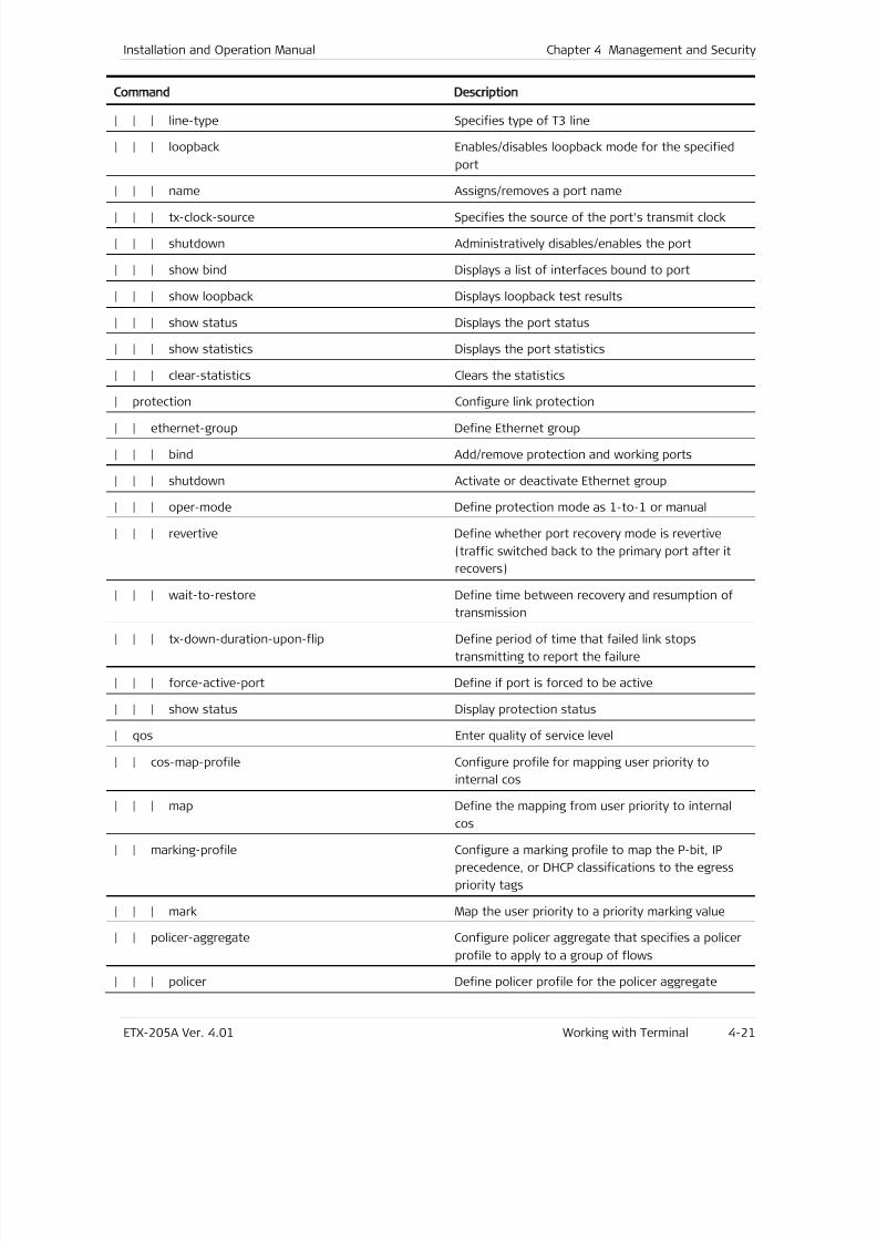
7/25/2019 Manual ETX-205A
http://slidepdf.com/reader/full/manual-etx-205a 89/409
Installation and Operation Manual Chapter 4 Management and Security
ETX-205A Ver. 4.01 Working with Terminal 4-21
Command Description
| | | line-type Specifies type of T3 line
| | | loopback Enables/disables loopback mode for the specified
port
| | | name Assigns/removes a port name
| | | tx-clock-source Specifies the source of the port's transmit clock
| | | shutdown Administratively disables/enables the port
| | | show bind Displays a list of interfaces bound to port
| | | show loopback Displays loopback test results
| | | show status Displays the port status
| | | show statistics Displays the port statistics
| | | clear-statistics Clears the statistics
| protection Configure link protection
| | ethernet-group Define Ethernet group
| | | bind Add/remove protection and working ports
| | | shutdown Activate or deactivate Ethernet group
| | | oper-mode Define protection mode as 1-to-1 or manual
| | | revertive Define whether port recovery mode is revertive
(traffic switched back to the primary port after it
recovers)
| | | wait-to-restore Define time between recovery and resumption of
transmission
| | | tx-down-duration-upon-flip Define period of time that failed link stops
transmitting to report the failure
| | | force-active-port Define if port is forced to be active
| | | show status Display protection status
| qos Enter quality of service level
| | cos-map-profile Configure profile for mapping user priority to
internal cos
| | | map Define the mapping from user priority to internal
cos
| | marking-profile Configure a marking profile to map the P-bit, IP
precedence, or DHCP classifications to the egress
priority tags
| | | mark Map the user priority to a priority marking value
| | policer-aggregate Configure policer aggregate that specifies a policer
profile to apply to a group of flows
| | | policer Define policer profile for the policer aggregate
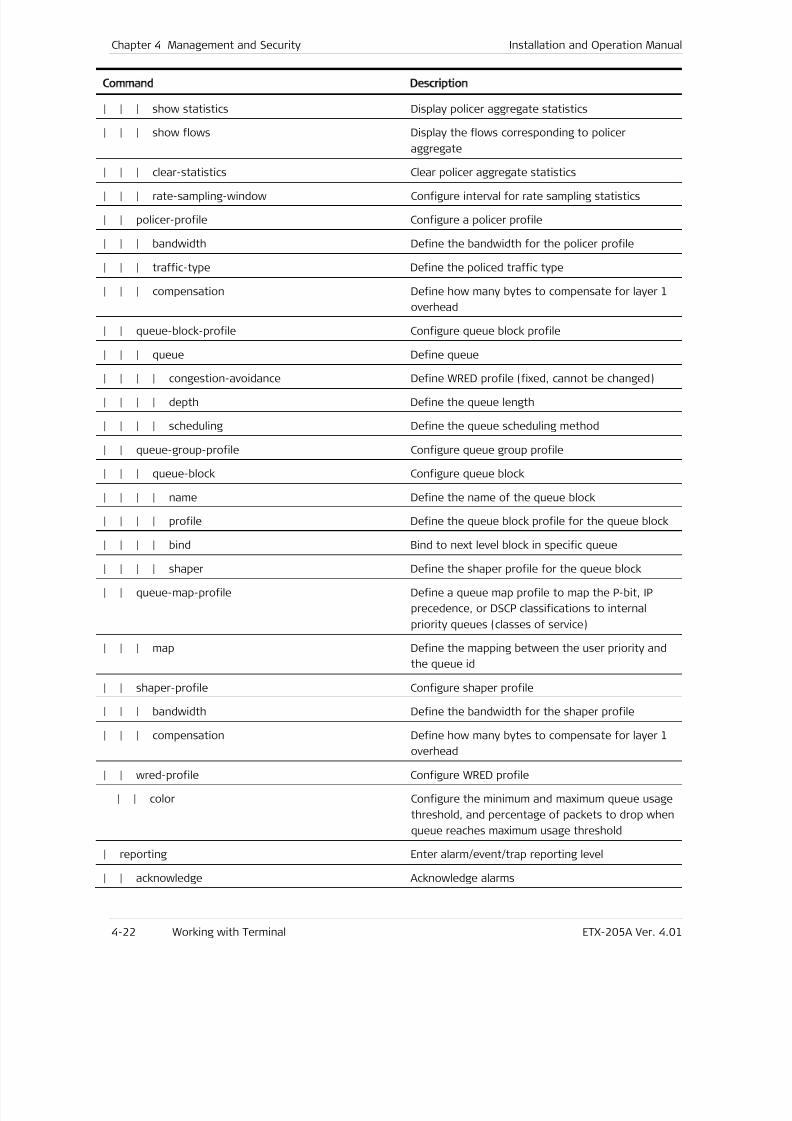
7/25/2019 Manual ETX-205A
http://slidepdf.com/reader/full/manual-etx-205a 90/409
Chapter 4 Management and Security Installation and Operation Manual
4-22 Working with Terminal ETX-205A Ver. 4.01
Command Description
| | | show statistics Display policer aggregate statistics
| | | show flows Display the flows corresponding to policer
aggregate
| | | clear-statistics Clear policer aggregate statistics
| | | rate-sampling-window Configure interval for rate sampling statistics
| | policer-profile Configure a policer profile
| | | bandwidth Define the bandwidth for the policer profile
| | | traffic-type Define the policed traffic type
| | | compensation Define how many bytes to compensate for layer 1
overhead
| | queue-block-profile Configure queue block profile
| | | queue Define queue
| | | | congestion-avoidance Define WRED profile (fixed, cannot be changed)
| | | | depth Define the queue length
| | | | scheduling Define the queue scheduling method
| | queue-group-profile Configure queue group profile
| | | queue-block Configure queue block
| | | | name Define the name of the queue block
| | | | profile Define the queue block profile for the queue block
| | | | bind Bind to next level block in specific queue
| | | | shaper Define the shaper profile for the queue block
| | queue-map-profile Define a queue map profile to map the P-bit, IP
precedence, or DSCP classifications to internal
priority queues (classes of service)
| | | map Define the mapping between the user priority and
the queue id
| | shaper-profile Configure shaper profile
| | | bandwidth Define the bandwidth for the shaper profile
| | | compensation Define how many bytes to compensate for layer 1
overhead
| | wred-profile Configure WRED profile
| | color Configure the minimum and maximum queue usage
threshold, and percentage of packets to drop when
queue reaches maximum usage threshold
| reporting Enter alarm/event/trap reporting level
| | acknowledge Acknowledge alarms
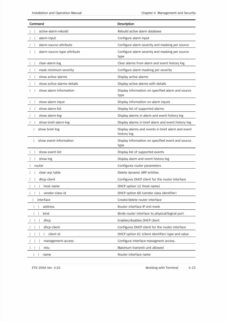
7/25/2019 Manual ETX-205A
http://slidepdf.com/reader/full/manual-etx-205a 91/409
Installation and Operation Manual Chapter 4 Management and Security
ETX-205A Ver. 4.01 Working with Terminal 4-23
Command Description
| | active-alarm-rebuild Rebuild active alarm database
| | alarm-input Configure alarm input
| | alarm-source-attribute Configure alarm severity and masking per source
| | alarm-source-type-attribute Configure alarm severity and masking per sourcetype
| | clear-alarm-log Clear alarms from alarm and event history log
| | mask-minimum-severity Configure alarm masking per severity
| | show active-alarms Display active alarms
| | show active-alarms-details Display active alarms with details
| | show alarm-information Display information on specified alarm and source
type
| | show alarm-input Display information on alarm inputs
| | show alarm-list Display list of supported alarms
| | show alarm-log Display alarms in alarm and event history log
| | show brief-alarm-log Display alarms in brief alarm and event history log
| show brief-log Display alarms and events in brief alarm and event
history log
| show event-information Display information on specified event and source
type
| | show event-list Display list of supported events
| | show log Display alarm and event history log
| router Configures router parameters
| | clear-arp-table Delete dynamic ARP entities
| | dhcp-client Configures DHCP client for the router interface
| | | host-name DHCP option 12 (host name)
| | | vendor-class-id DHCP option 60 (vendor class identifier)
| interface Create/delete router interface
| | address Router interface IP and mask
| | bind Binds router interface to physical/logical port
| | | dhcp Enables/disables DHCP client
| | | dhcp-client Configures DHCP client for the router interface
| | | | client-id DHCP option 61 (client identifier) type and value
| | | management-access Configure interface managment access.
| | | mtu Maximum transmit unit allowed
| | name Router interface name
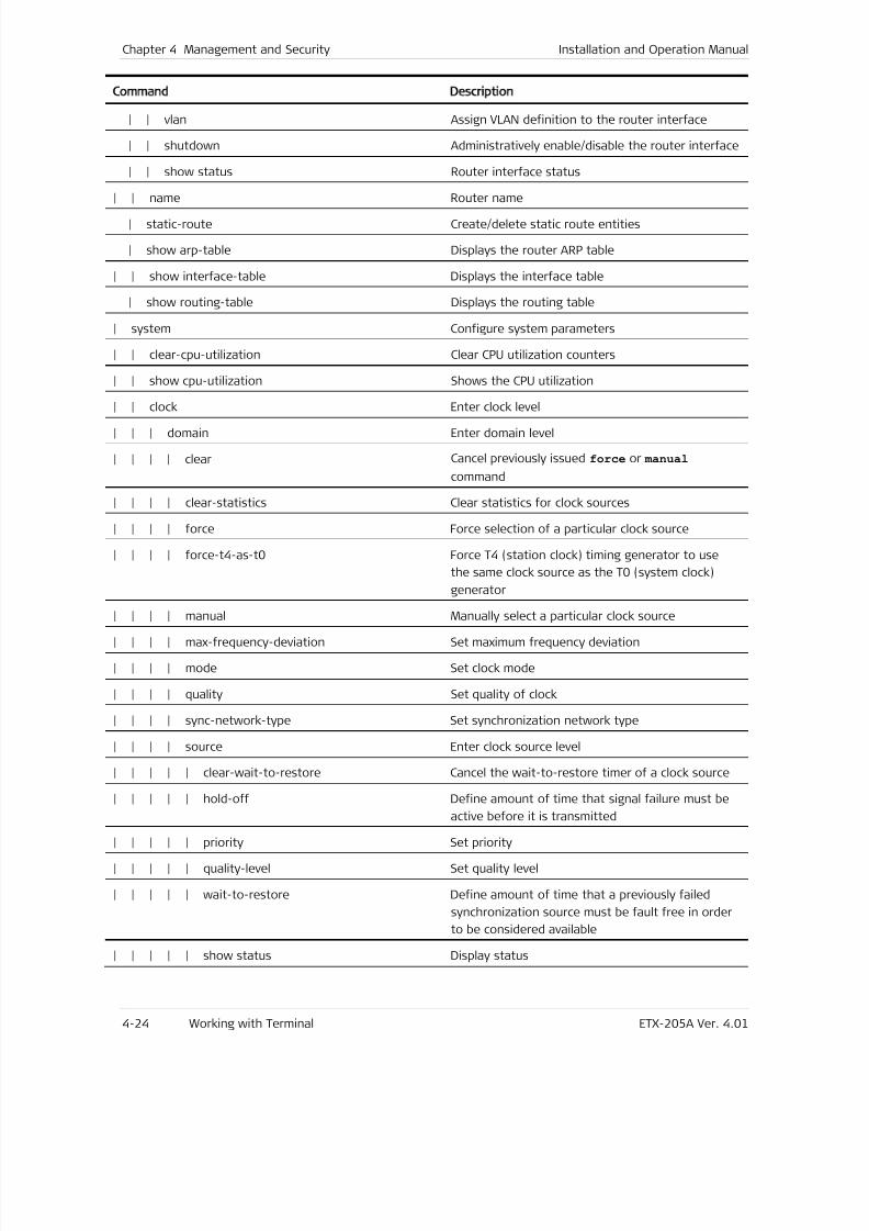
7/25/2019 Manual ETX-205A
http://slidepdf.com/reader/full/manual-etx-205a 92/409
Chapter 4 Management and Security Installation and Operation Manual
4-24 Working with Terminal ETX-205A Ver. 4.01
Command Description
| | vlan Assign VLAN definition to the router interface
| | shutdown Administratively enable/disable the router interface
| | show status Router interface status
| | name Router name| static-route Create/delete static route entities
| show arp-table Displays the router ARP table
| | show interface-table Displays the interface table
| show routing-table Displays the routing table
| system Configure system parameters
| | clear-cpu-utilization Clear CPU utilization counters
| | show cpu-utilization Shows the CPU utilization
| | clock Enter clock level
| | | domain Enter domain level
| | | | clear Cancel previously issued force or manual
command
| | | | clear-statistics Clear statistics for clock sources
| | | | force Force selection of a particular clock source
| | | | force-t4-as-t0 Force T4 (station clock) timing generator to use
the same clock source as the T0 (system clock)
generator
| | | | manual Manually select a particular clock source
| | | | max-frequency-deviation Set maximum frequency deviation
| | | | mode Set clock mode
| | | | quality Set quality of clock
| | | | sync-network-type Set synchronization network type
| | | | source Enter clock source level
| | | | | clear-wait-to-restore Cancel the wait-to-restore timer of a clock source
| | | | | hold-off Define amount of time that signal failure must be
active before it is transmitted
| | | | | priority Set priority
| | | | | quality-level Set quality level
| | | | | wait-to-restore Define amount of time that a previously failed
synchronization source must be fault free in order
to be considered available
| | | | | show status Display status
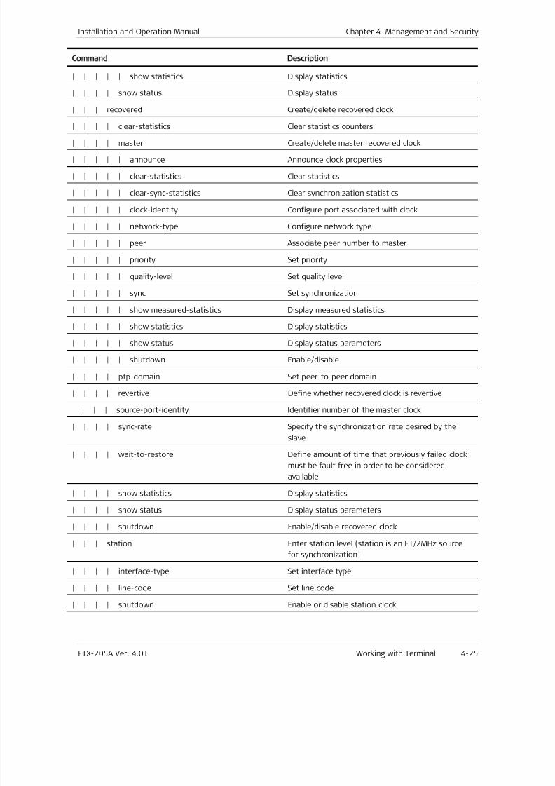
7/25/2019 Manual ETX-205A
http://slidepdf.com/reader/full/manual-etx-205a 93/409
Installation and Operation Manual Chapter 4 Management and Security
ETX-205A Ver. 4.01 Working with Terminal 4-25
Command Description
| | | | | show statistics Display statistics
| | | | show status Display status
| | | recovered Create/delete recovered clock
| | | | clear-statistics Clear statistics counters| | | | master Create/delete master recovered clock
| | | | | announce Announce clock properties
| | | | | clear-statistics Clear statistics
| | | | | clear-sync-statistics Clear synchronization statistics
| | | | | clock-identity Configure port associated with clock
| | | | | network-type Configure network type
| | | | | peer Associate peer number to master
| | | | | priority Set priority
| | | | | quality-level Set quality level
| | | | | sync Set synchronization
| | | | | show measured-statistics Display measured statistics
| | | | | show statistics Display statistics
| | | | | show status Display status parameters
| | | | | shutdown Enable/disable
| | | | ptp-domain Set peer-to-peer domain
| | | | revertive Define whether recovered clock is revertive
| | | source-port-identity Identifier number of the master clock
| | | | sync-rate Specify the synchronization rate desired by the
slave
| | | | wait-to-restore Define amount of time that previously failed clock
must be fault free in order to be considered
available
| | | | show statistics Display statistics
| | | | show status Display status parameters
| | | | shutdown Enable/disable recovered clock
| | | station Enter station level (station is an E1/2MHz source
for synchronization)
| | | | interface-type Set interface type
| | | | line-code Set line code
| | | | shutdown Enable or disable station clock
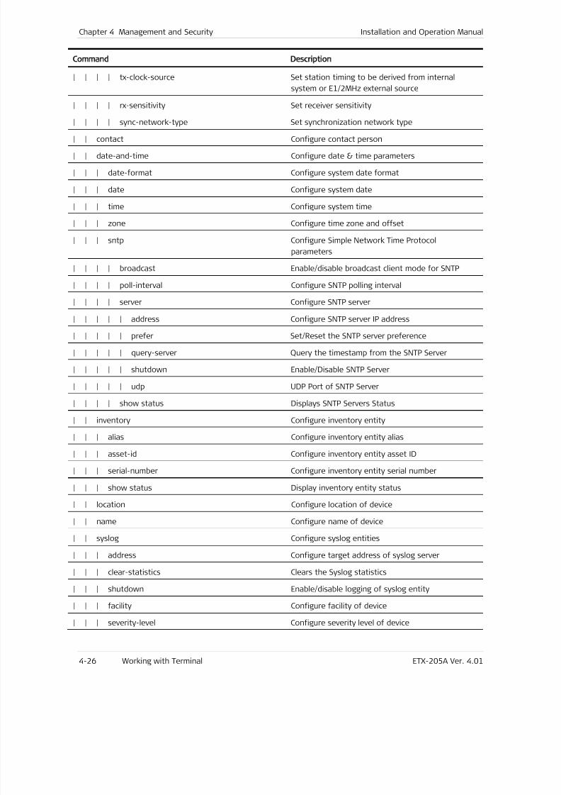
7/25/2019 Manual ETX-205A
http://slidepdf.com/reader/full/manual-etx-205a 94/409
Chapter 4 Management and Security Installation and Operation Manual
4-26 Working with Terminal ETX-205A Ver. 4.01
Command Description
| | | | tx-clock-source Set station timing to be derived from internal
system or E1/2MHz external source
| | | | rx-sensitivity Set receiver sensitivity
| | | | sync-network-type Set synchronization network type
| | contact Configure contact person
| | date-and-time Configure date & time parameters
| | | date-format Configure system date format
| | | date Configure system date
| | | time Configure system time
| | | zone Configure time zone and offset
| | | sntp Configure Simple Network Time Protocol
parameters
| | | | broadcast Enable/disable broadcast client mode for SNTP
| | | | poll-interval Configure SNTP polling interval
| | | | server Configure SNTP server
| | | | | address Configure SNTP server IP address
| | | | | prefer Set/Reset the SNTP server preference
| | | | | query-server Query the timestamp from the SNTP Server
| | | | | shutdown Enable/Disable SNTP Server
| | | | | udp UDP Port of SNTP Server
| | | | show status Displays SNTP Servers Status
| | inventory Configure inventory entity
| | | alias Configure inventory entity alias
| | | asset-id Configure inventory entity asset ID
| | | serial-number Configure inventory entity serial number
| | | show status Display inventory entity status
| | location Configure location of device
| | name Configure name of device
| | syslog Configure syslog entities
| | | address Configure target address of syslog server
| | | clear-statistics Clears the Syslog statistics
| | | shutdown Enable/disable logging of syslog entity
| | | facility Configure facility of device
| | | severity-level Configure severity level of device
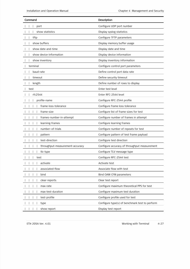
7/25/2019 Manual ETX-205A
http://slidepdf.com/reader/full/manual-etx-205a 95/409
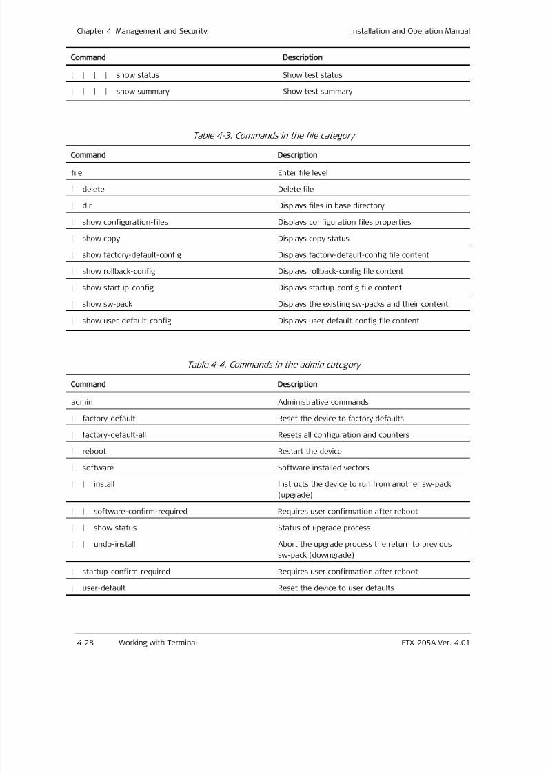
7/25/2019 Manual ETX-205A
http://slidepdf.com/reader/full/manual-etx-205a 96/409
Chapter 4 Management and Security Installation and Operation Manual
4-28 Working with Terminal ETX-205A Ver. 4.01
Command Description
| | | | show status Show test status
| | | | show summary Show test summary
Table 4-3. Commands in the file category
Command Description
file Enter file level
| delete Delete file
| dir Displays files in base directory
| show configuration-files Displays configuration files properties
| show copy Displays copy status
| show factory-default-config Displays factory-default-config file content
| show rollback-config Displays rollback-config file content
| show startup-config Displays startup-config file content
| show sw-pack Displays the existing sw-packs and their content
| show user-default-config Displays user-default-config file content
Table 4-4. Commands in the admin category
Command Description
admin Administrative commands
| factory-default Reset the device to factory defaults
| factory-default-all Resets all configuration and counters
| reboot Restart the device
| software Software installed vectors
| | install Instructs the device to run from another sw-pack
(upgrade)
| | software-confirm-required Requires user confirmation after reboot
| | show status Status of upgrade process
| | undo-install Abort the upgrade process the return to previous
sw-pack (downgrade)
| startup-confirm-required Requires user confirmation after reboot
| user-default Reset the device to user defaults
7/25/2019 Manual ETX-205A
http://slidepdf.com/reader/full/manual-etx-205a 97/409
Installation and Operation Manual Chapter 4 Management and Security
ETX-205A Ver. 4.01 Working with Telnet and SSH 4-29
Table 4-5. Commands in the root category
Command Description
clear-statistics Clear statistics for Ethernet ports, flows, and OAM
services
on-configuration-error Determines the device behavior when encountering
an error in configuration file
Table 4-6. Commands in the global-commands category
Command Description
global-commands Global commands can be typed at any level
| exit Return to previous level in the commands hierarchy
| tree Displays all lower command levels and commands
accessible from the current context level, optionallywith parameter information
| help Displays general help, or optionally just the hotkeys
and/or global commands
| history Displays the command history for the current
session (by default the history contains the last 10
commands)
| echo Echo the text that is typed in
| exec Execute a file, optionally echoing the commands
| logout Log out this system
| info Displays information on the current configuration
| level-info Displays the current device configuration –
commands from the current level only
| ping Verify the reachability of a remote host
| copy Copy files
| save Save user configuration
| trace-route Determine the route to a destination address
4.2 Working with Telnet and SSH
Typically, the Telnet host is a PC or Unix station with the appropriate suite of
TCP/IP protocols.
To enable the Telnet host to communicate with ETX-205A, it is necessary to
configure the ETX-205A IP address settings (refer to the Router section in
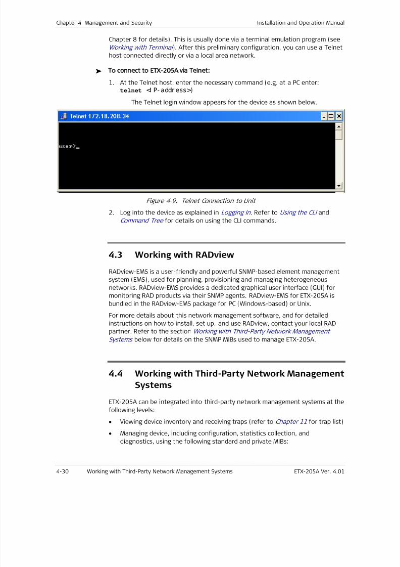
7/25/2019 Manual ETX-205A
http://slidepdf.com/reader/full/manual-etx-205a 98/409
Chapter 4 Management and Security Installation and Operation Manual
4-30 Working with Third-Party Network Management Systems ETX-205A Ver. 4.01
Chapter 8 for details). This is usually done via a terminal emulation program (see
Working with Terminal ). After this preliminary configuration, you can use a Telnet
host connected directly or via a local area network.
To connect to ETX-205A via Telnet:
1. At the Telnet host, enter the necessary command (e.g. at a PC enter:telnet <I P- addr ess>)
The Telnet login window appears for the device as shown below.
Figure 4-9. Telnet Connection to Unit
2. Log into the device as explained in Logging In . Refer to Using the CLI and
Command Tree for details on using the CLI commands.
4.3 Working with RADview
RADview-EMS is a user-friendly and powerful SNMP-based element management
system (EMS), used for planning, provisioning and managing heterogeneousnetworks. RADview-EMS provides a dedicated graphical user interface (GUI) for
monitoring RAD products via their SNMP agents. RADview-EMS for ETX-205A is
bundled in the RADview-EMS package for PC (Windows-based) or Unix.
For more details about this network management software, and for detailed
instructions on how to install, set up, and use RADview, contact your local RAD
partner. Refer to the section Working with Third-Party Network Management
Systems below for details on the SNMP MIBs used to manage ETX-205A.
4.4
Working with Third-Party Network ManagementSystems
ETX-205A can be integrated into third-party network management systems at the
following levels:
• Viewing device inventory and receiving traps (refer to Chapter 11 for trap list)
• Managing device, including configuration, statistics collection, and
diagnostics, using the following standard and private MIBs:
7/25/2019 Manual ETX-205A
http://slidepdf.com/reader/full/manual-etx-205a 99/409
Installation and Operation Manual Chapter 4 Management and Security
ETX-205A Ver. 4.01 SNMP Management 4-31
CFM MIB (IEEE8021-CFM-MIB)
IANAifType-MIB
IETF Syslog Device MIB
IEEE8023-LAG-MIB
MEF-R MIB
RAD private MIB
RFC 2819 (RMON-MIB)
RFC 2863 (IF-MIB)
RFC 3273 (Remote Network Monitoring MIB)
RFC 3411 (SNMP-FRAMEWORK-MIB)
RFC 3413 (SNMP-TARGET-MIB)
RFC 3414 (SNMP-USER-BASED-SM-MIB)
RFC 3415 (SNMP-VIEW-BASED-ACM-MIB)
RFC 3418 (SNMPv2-MIB)
RFC 3433 (ENTITY-SENSOR-MIB)
RFC 3636 (MAU-MIB)
RFC 4133 (ENTITY-MIB)
RFC 4668 (RADIUS-AUTH-CLIENT-MIB)
RFC 4836.MIB (MAU-MIB)
RFC 4878.MIB (DOT3-OAM-MIB).
4.5 SNMP Management
SNMP stands for Simple Network Management Protocol and is an application layer
protocol that provides a message format for communication between managers
and agents.
ETX-205A supports SNMPv3, the latest SNMP version to date. SNMPv3 provides
secure access to devices in the network by using authentication and data
encryption.
Standards
The supported SNMP versions are based on the following standards:
• RFC 1901, Introduction to Community-Based SNMPv2. SNMPv2 Working
Group.
• RFC 1902, Structure of Management Information for Version 2 of the Simple
Network Management Protocol (SNMPv2). SNMPv2 Working Group.
7/25/2019 Manual ETX-205A
http://slidepdf.com/reader/full/manual-etx-205a 100/409
Chapter 4 Management and Security Installation and Operation Manual
4-32 SNMP Management ETX-205A Ver. 4.01
• RFC 1903, Textual Conventions for Version 2 of the Simple Network
Management Protocol (SNMPv2). SNMPv2 Working Group.
• RFC 1904, Conformance Statements for Version 2 of the Simple Network
Management Protocol (SNMPv2). SNMPv2 Working Group.
• RFC 1905, Protocol Operations for Version 2 of the Simple Network
Management Protocol (SNMPv2). SNMPv2 Working Group.
• RFC 1906, Transport Mappings for Version 2 of the Simple Network
Management Protocol (SNMPv2).
• RFC 1907, Management Information Base for Version 2 of the Simple
Network Management Protocol (SNMPv2). SNMPv2 Working Group.
• RFC 1908, Coexistence between Version 1 and Version 2 of the Internet-
standard Network Management Framework. SNMPv2 Working Group.
• RFC 2104, Keyed Hashing for Message Authentication.
• RFC 2271, Architecture for Describing SNMP Management Frameworks.
• RFC 2272, message processing and dispatching for the Simple Network
Management Protocol (SNMP).
• RFC 2273, SNMPv3 Applications.
• RFC 2274, User-Based Security Model (USM) for version 3 of the Simple
Network Management Protocol (SNMPv3).
• RFC 2275, View-Based Access Control Model (VACM) for the Simple Network
Management Protocol (SNMP).
• RFC 3412, Version 3 Message Processing and Dispatching.
• RFC 3414, User-based Security Model for SNMPv3
• RFC 3416, Update for RFC 1904.
Benefits
The SNMP protocol allows you to remotely manage multiple units from a central
workstation using a network management system.
The SNMPv3 protocol allows data to be collected securely from SNMP devices.
Confidential information such as SNMP commands can thus be encrypted to
prevent unauthorized parties from being able to access them.
Functional Description
In an SNMP configuration, one or more administrative computers manage a group
of hosts or devices. Each managed system continuously executes a software
component called agent, which reports information via SNMP back to the
managing workstations.
Factory Defaults
The following is the default configuration of the SNMP parameters (refer to
Configuring SNMPv3 Parameters for explanations of the parameters):
7/25/2019 Manual ETX-205A
http://slidepdf.com/reader/full/manual-etx-205a 101/409
Installation and Operation Manual Chapter 4 Management and Security
ETX-205A Ver. 4.01 SNMP Management 4-33
• SNMP engine ID set to device MAC address
• View named “internet” providing access to IETF MIBs and IEEE MIBs
• User named "initial", with security level no authentication and no privacy
• Group for SNMPv3 named "initial":
Security levels: no authentication and no privacy, authentication and no
privacy, authentication and privacy
User: “initial”
Views for read/write/notify: "internet".
• Notifications with tag “unmasked” for the device traps.
Configuring SNMPv3 Parameters
ETX-205A supports SNMP version 3, providing secure SNMP access to the device
by authenticating and encrypting packets transmitted over the network.
The SNMPv3 manager application in RADview-EMS provides a user-friendly GUI
interface to configure SNMPv3 parameters. If you intend to use it, you must first
use the device CLI to create users with the required encryption method and
security level, as the application can create users based only on existing users;
the new user has the same encryption method, and the same security level or
lower. The ETX-205A default configuration provides one standard user named
“initial” with no encryption and the lowest security level (refer to Factory
Defaults for details).
Follow this procedure to configure SNMPv3:
1. Set SNMP engine ID if necessary
2. Add users, specifying authentication protocol and privacy protocol
3. Add groups, specifying security level, protocol, and views
4. Connect users to groups
5. Add notification entries with assigned traps and tags
6. Configure target parameter sets to be used for targets
7. Configure targets (SNMPv3 network management stations to which ETX-205A
should send trap notifications), specifying target parameter sets, notification
tags, and trap synchronization groups if applicable
To configure SNMPv3 parameters:
1.
Navigate to configure management snmp.The config>mngmnt>snmp prompt is displayed.
2. Enter all necessary commands according to the tasks listed below.
When you enter password parameters, they should contain at least eight
characters.
Note
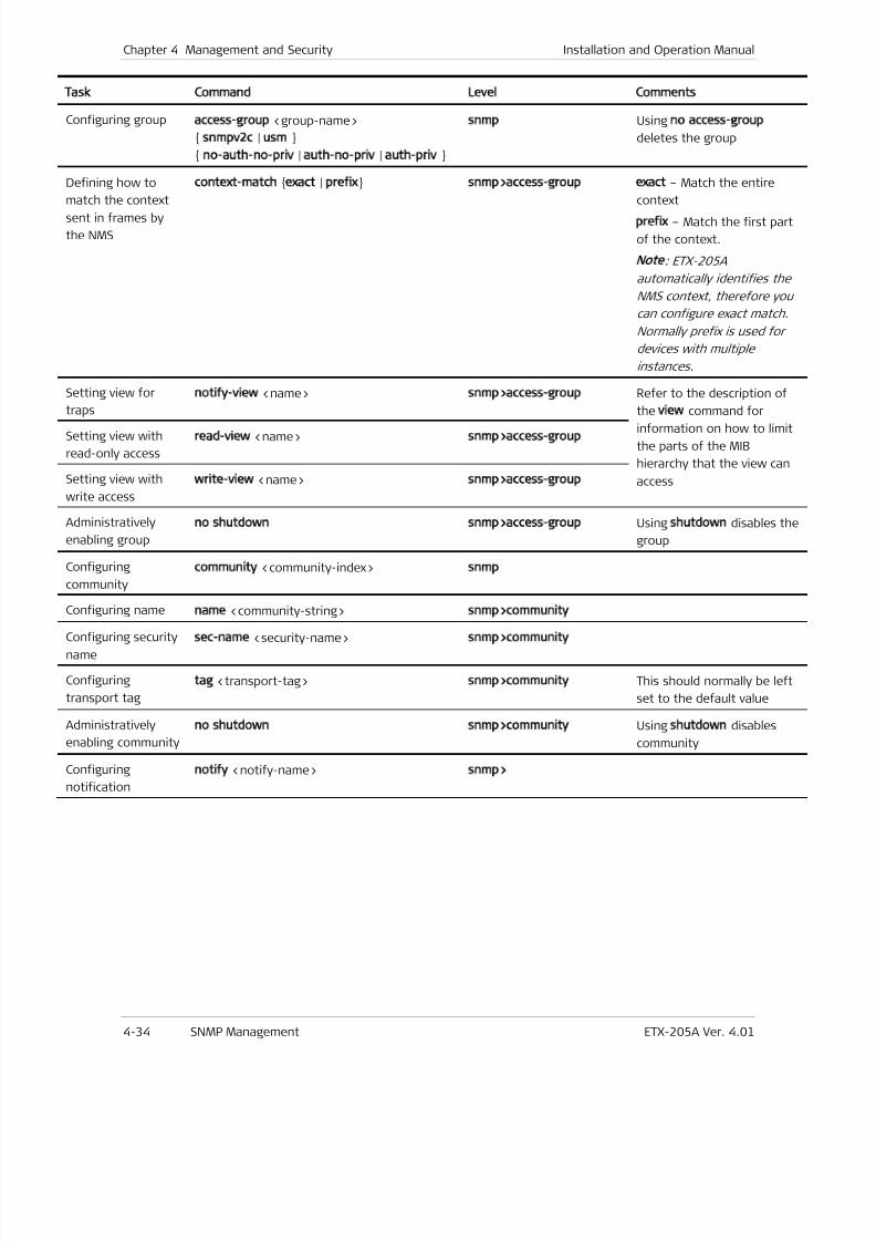
7/25/2019 Manual ETX-205A
http://slidepdf.com/reader/full/manual-etx-205a 102/409
Chapter 4 Management and Security Installation and Operation Manual
4-34 SNMP Management ETX-205A Ver. 4.01
Task Command Level Comments
Configuring group access-group
<group-name>
snmpv2c
|usm
no-auth-no-priv
|auth-no-priv
|auth-priv
snmp
Usingno access-group
deletes the group
Defining how to
match the contextsent in frames by
the NMS
context-match exact | prefix snmp>access-group exact – Match the entire
contextprefix – Match the first part
of the context.
Note
: ETX-205A
automatically identifies the
NMS context, therefore you
can configure exact match.
Normally prefix is used for
devices with multiple
instances.
Setting view for
traps
notify-view
<name>snmp>access-group
Refer to the description of
the view command forinformation on how to limit
the parts of the MIB
hierarchy that the view can
access
Setting view with
read-only access
read-view
<name>snmp>access-group
Setting view with
write access
write-view <name> snmp>access-group
Administratively
enabling group
no shutdown snmp>access-group Using shutdown disables the
group
Configuring
community
community
<community-index>snmp
Configuring namename
<community-string>snmp>community
Configuring security
name
sec-name <security-name> snmp>community
Configuring
transport tag
tag
<transport-tag>snmp>community
This should normally be left
set to the default value
Administratively
enabling community
no shutdown snmp>community
Usingshutdown
disables
community
Configuring
notification
notify
<notify-name>snmp>
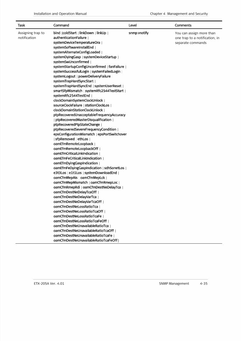
7/25/2019 Manual ETX-205A
http://slidepdf.com/reader/full/manual-etx-205a 103/409
Installation and Operation Manual Chapter 4 Management and Security
ETX-205A Ver. 4.01 SNMP Management 4-35
Task Command Level Comments
Assigning trap to
notification
bind
coldStart
|linkDown
|linkUp
|
authenticationFailure
|
systemDeviceTemperatureOra
|
systemSoftwareInstallEnd
|
systemAlternateConfigLoaded |
systemDyingGasp | systemDeviceStartup |systemSwUnconfirmed |
systemStartupConfigUnconfirmed
|fanFailure
|
systemSuccessfulLogin | systemFailedLogin |
systemLogout
|powerDeliveryFailure
|
systemTrapHardSyncStart |
systemTrapHardSyncEnd
|systemUserReset
|
smartSfpMismatch | systemRfc2544TestStart |
systemRfc2544TestEnd
|
clockDomainSystemClockUnlock |
sourceClockFailure
|stationClockLos
|
clockDomainStationClockUnlock
|
ptpRecoveredUnacceptableFrequencyAccuracy
|ptpRecoveredMasterDisqualification
|
ptpRecoveredPtpStateChange |
ptpRecoveredSevereFrequencyCondition
|
epsConfigurationMismatch | epsPortSwitchover
|sfpRemoved
|ethLos
|
oamEfmRemoteLoopback |
oamEfmRemoteLoopbackOff
|
oamEfmCriticalLinkIndication |
oamEfmFeCriticalLinkIndication
|
oamEfmDyingGaspIndication |
oamEfmFeDyingGaspIndication
|sdhSonetLos
|
e3t3Los | e1t1Los | systemDownloadEnd |
oamCfmMepAis
|oamCfmMepLck
|
oamCfmMepMismatch | oamCfmRmepLoc |
oamCfmRmepRdi
|oamCfmDestNeDelayTca
|
oamCfmDestNeDelayTcaOff
|
oamCfmDestNeDelayVarTca
|
oamCfmDestNeDelayVarTcaOff
|
oamCfmDestNeLossRatioTca |
oamCfmDestNeLossRatioTcaOff
|
oamCfmDestNeLossRatioTcaFe |
oamCfmDestNeLossRatioTcaFeOff
|
oamCfmDestNeUnavailableRatioTca |oamCfmDestNeUnavailableRatioTcaOff
|
oamCfmDestNeUnavailableRatioTcaFe |
oamCfmDestNeUnavailableRatioTcaFeOff
snmp>notify
You can assign more than
one trap to a notification, in
separate commands
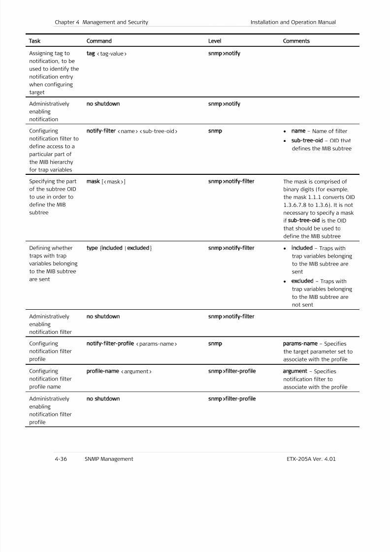
7/25/2019 Manual ETX-205A
http://slidepdf.com/reader/full/manual-etx-205a 104/409
Chapter 4 Management and Security Installation and Operation Manual
4-36 SNMP Management ETX-205A Ver. 4.01
Task Command Level Comments
Assigning tag to
notification, to be
used to identify the
notification entry
when configuring
target
tag
<tag-value>snmp>notify
Administratively
enabling
notification
no shutdown snmp>notify
Configuring
notification filter to
define access to a
particular part of
the MIB hierarchy
for trap variables
notify-filter <name> <sub-tree-oid> snmp • name – Name of filter
• sub-tree-oid
– OID that
defines the MIB subtree
Specifying the partof the subtree OID
to use in order to
define the MIB
subtree
mask [<mask>] snmp>notify-filter The mask is comprised ofbinary digits (for example,
the mask 1.1.1 converts OID
1.3.6.7.8 to 1.3.6). It is not
necessary to specify a mask
ifsub-tree-oid
is the OID
that should be used to
define the MIB subtree
Defining whether
traps with trap
variables belonging
to the MIB subtree
are sent
type included | excluded snmp>notify-filter • included – Traps with
trap variables belonging
to the MIB subtree are
sent
• excluded – Traps with
trap variables belonging
to the MIB subtree are
not sent
Administratively
enabling
notification filter
no shutdown snmp>notify-filter
Configuring
notification filter
profile
notify-filter-profile
<params-name>snmp params-name
– Specifies
the target parameter set to
associate with the profile
Configuring
notification filter
profile name
profile-name
<argument>snmp>filter-profile argument
– Specifies
notification filter to
associate with the profile
Administratively
enabling
notification filter
profile
no shutdown snmp>filter-profile
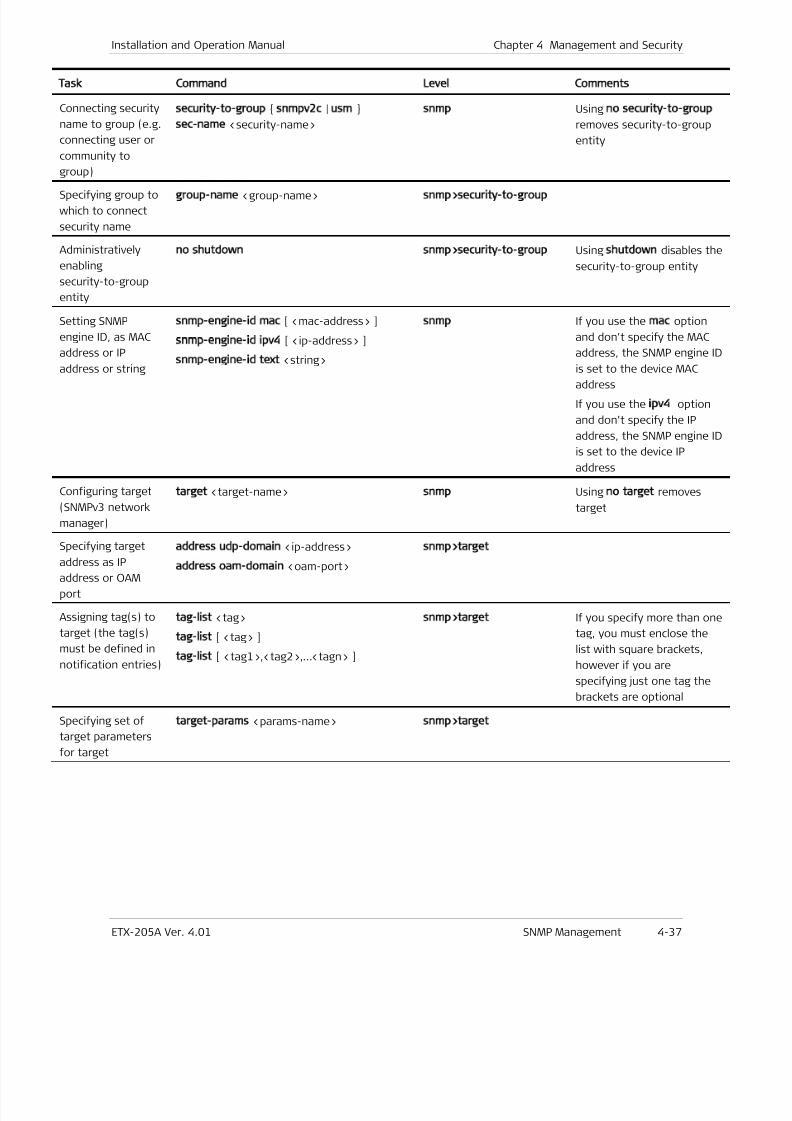
7/25/2019 Manual ETX-205A
http://slidepdf.com/reader/full/manual-etx-205a 105/409
Installation and Operation Manual Chapter 4 Management and Security
ETX-205A Ver. 4.01 SNMP Management 4-37
Task Command Level Comments
Connecting security
name to group (e.g.
connecting user or
community to
group)
security-to-group
snmpv2c
|usm
sec-name
<security-name>
snmp
Usingno security-to-group
removes security-to-group
entity
Specifying group to
which to connect
security name
group-name <group-name> snmp>security-to-group
Administratively
enabling
security-to-group
entity
no shutdown snmp>security-to-group
Usingshutdown
disables the
security-to-group entity
Setting SNMP
engine ID, as MAC
address or IP
address or string
snmp-engine-id
mac
[ <mac-address> ]
snmp-engine-id ipv4 [ <ip-address> ]
snmp-engine-id text
<string>
snmp
If you use themac
option
and don’t specify the MAC
address, the SNMP engine ID
is set to the device MACaddress
If you use the ipv4 option
and don’t specify the IP
address, the SNMP engine ID
is set to the device IP
address
Configuring target
(SNMPv3 network
manager)
target
<target-name>snmp
Usingno target
removes
target
Specifying target
address as IP
address or OAM
port
address udp-domain
<ip-address>
address
oam-domain
<oam-port>
snmp>target
Assigning tag(s) to
target (the tag(s)
must be defined in
notification entries)
tag-list
<tag>
tag-list [ <tag> ]
tag-list
[ <tag1>,<tag2>,…<tagn> ]
snmp>target
If you specify more than one
tag, you must enclose the
list with square brackets,
however if you are
specifying just one tag the
brackets are optional
Specifying set of
target parameters
for target
target-params
<params-name>snmp>target
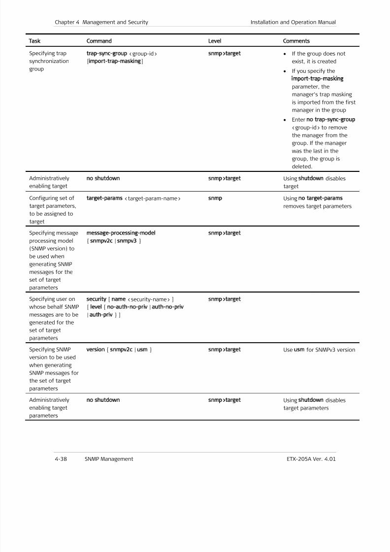
7/25/2019 Manual ETX-205A
http://slidepdf.com/reader/full/manual-etx-205a 106/409
Chapter 4 Management and Security Installation and Operation Manual
4-38 SNMP Management ETX-205A Ver. 4.01
Task Command Level Comments
Specifying trap
synchronization
group
trap-sync-group
<group-id>
[import-trap-masking
]
snmp>target • If the group does not
exist, it is created
• If you specify the
import-trap-masking
parameter, the
manager’s trap masking
is imported from the first
manager in the group
• Enterno trap-sync-group
<group-id> to remove
the manager from the
group. If the manager
was the last in the
group, the group is
deleted.
Administratively
enabling target
no shutdown snmp>target
Usingshutdown
disables
target
Configuring set of
target parameters,
to be assigned to
target
target-params <target-param-name> snmp Using no target-params
removes target parameters
Specifying message
processing model
(SNMP version) to
be used when
generating SNMP
messages for the
set of target
parameters
message-processing-model
snmpv2c
|snmpv3
snmp>target
Specifying user on
whose behalf SNMP
messages are to be
generated for the
set of target
parameters
security [ name <security-name> ]
[level
no-auth-no-priv
|auth-no-priv
| auth-priv ]
snmp>target
Specifying SNMP
version to be used
when generatingSNMP messages for
the set of target
parameters
version snmpv2c | usm snmp>target Use usm for SNMPv3 version
Administratively
enabling target
parameters
no shutdown snmp>target Using shutdown disables
target parameters
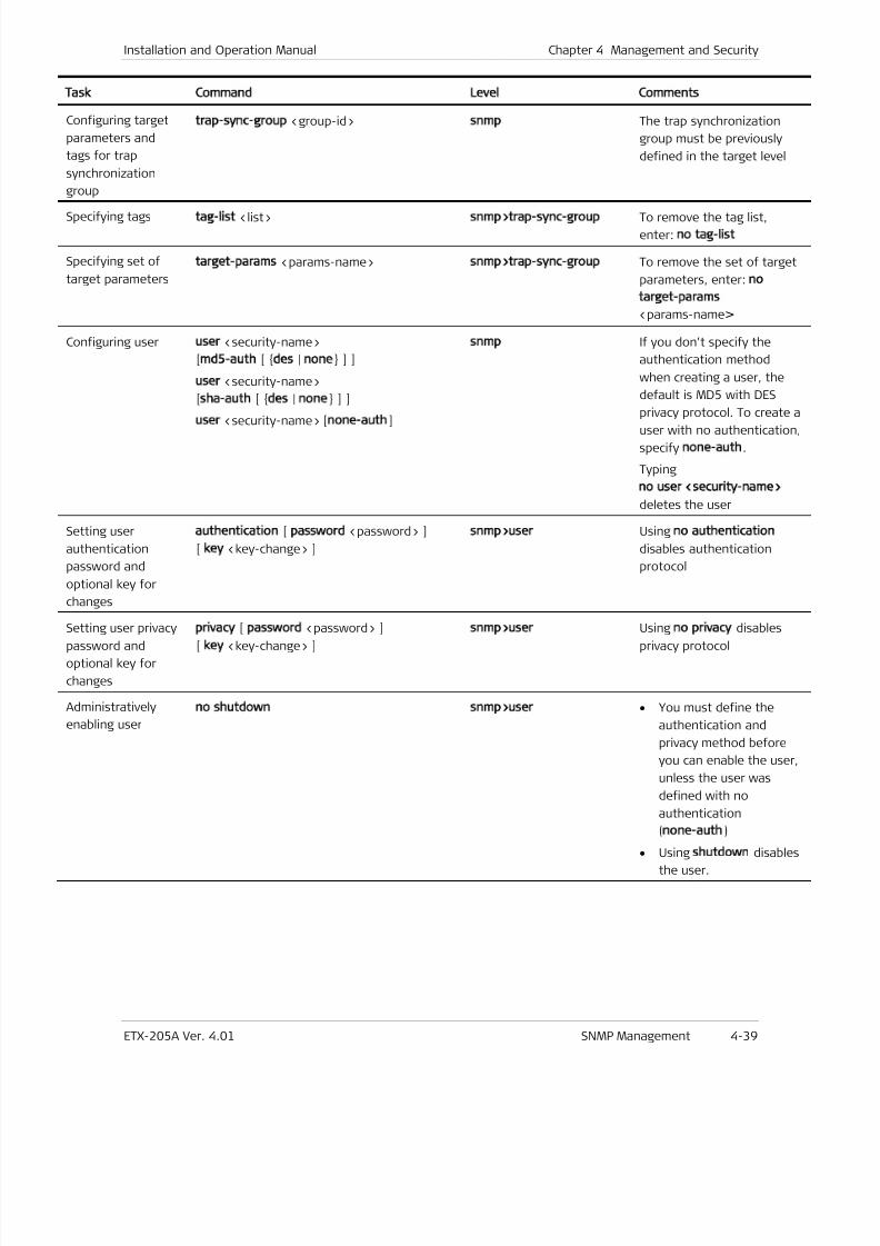
7/25/2019 Manual ETX-205A
http://slidepdf.com/reader/full/manual-etx-205a 107/409
Installation and Operation Manual Chapter 4 Management and Security
ETX-205A Ver. 4.01 SNMP Management 4-39
Task Command Level Comments
Configuring target
parameters and
tags for trap
synchronization
group
trap-sync-group
<group-id>snmp
The trap synchronization
group must be previously
defined in the target level
Specifying tagstag-list <list> snmp>trap-sync-group To remove the tag list,
enter:no tag-list
Specifying set of
target parameters
target-params <params-name> snmp>trap-sync-group To remove the set of target
parameters, enter:no
target-params
<params-name>
Configuring user user <security-name>
[md5-auth
[ des
|none
] ]
user <security-name>
[sha-auth
[ des
|none
] ]
user
<security-name> [none-auth
]
snmp If you don’t specify the
authentication method
when creating a user, the
default is MD5 with DES
privacy protocol. To create auser with no authentication,
specify none-auth.
Typing
no user <security-name>
deletes the user
Setting user
authentication
password and
optional key for
changes
authentication
[password
<password> ]
[ key <key-change> ]
snmp>user
Usingno authentication
disables authentication
protocol
Setting user privacy
password and
optional key for
changes
privacy
[password
<password> ]
[ key <key-change> ]
snmp>user
Usingno privacy
disables
privacy protocol
Administratively
enabling user
no shutdown snmp>user • You must define the
authentication and
privacy method before
you can enable the user,
unless the user was
defined with no
authentication
(none-auth)
• Using shutdown disables
the user.
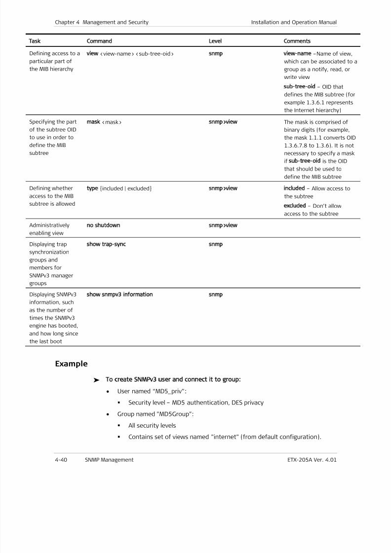
7/25/2019 Manual ETX-205A
http://slidepdf.com/reader/full/manual-etx-205a 108/409
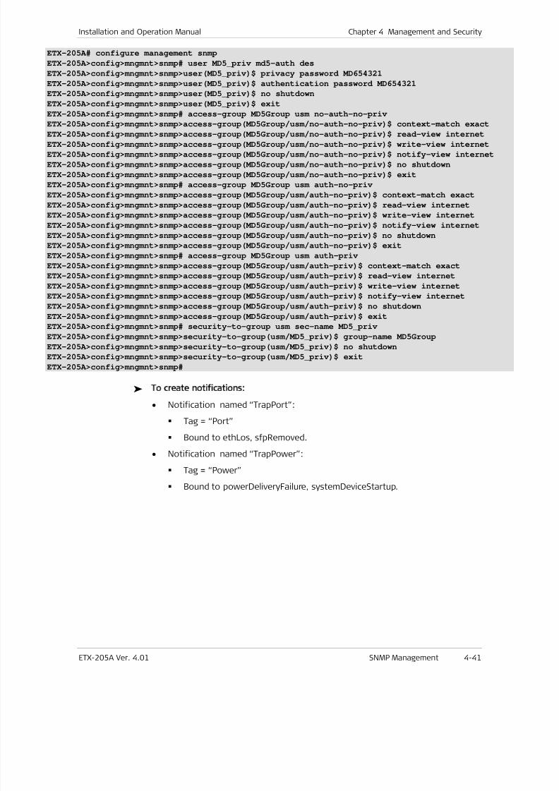
7/25/2019 Manual ETX-205A
http://slidepdf.com/reader/full/manual-etx-205a 109/409
Installation and Operation Manual Chapter 4 Management and Security
ETX-205A Ver. 4.01 SNMP Management 4-41
ETX-205A# configure management snmp
ETX-205A>config>mngmnt>snmp# user MD5_priv md5-auth des
ETX-205A>config>mngmnt>snmp>user(MD5_priv)$ privacy password MD654321
ETX-205A>config>mngmnt>snmp>user(MD5_priv)$ authentication password MD654321
ETX-205A>config>mngmnt>snmp>user(MD5_priv)$ no shutdown
ETX-205A>config>mngmnt>snmp>user(MD5_priv)$ exit
ETX-205A>config>mngmnt>snmp# access-group MD5Group usm no-auth-no-priv
ETX-205A>config>mngmnt>snmp>access-group(MD5Group/usm/no-auth-no-priv)$ context-match exact
ETX-205A>config>mngmnt>snmp>access-group(MD5Group/usm/no-auth-no-priv)$ read-view internet
ETX-205A>config>mngmnt>snmp>access-group(MD5Group/usm/no-auth-no-priv)$ write-view internet
ETX-205A>config>mngmnt>snmp>access-group(MD5Group/usm/no-auth-no-priv)$ notify-view internet
ETX-205A>config>mngmnt>snmp>access-group(MD5Group/usm/no-auth-no-priv)$ no shutdown
ETX-205A>config>mngmnt>snmp>access-group(MD5Group/usm/no-auth-no-priv)$ exit
ETX-205A>config>mngmnt>snmp# access-group MD5Group usm auth-no-priv
ETX-205A>config>mngmnt>snmp>access-group(MD5Group/usm/auth-no-priv)$ context-match exact
ETX-205A>config>mngmnt>snmp>access-group(MD5Group/usm/auth-no-priv)$ read-view internet
ETX-205A>config>mngmnt>snmp>access-group(MD5Group/usm/auth-no-priv)$ write-view internet
ETX-205A>config>mngmnt>snmp>access-group(MD5Group/usm/auth-no-priv)$ notify-view internet
ETX-205A>config>mngmnt>snmp>access-group(MD5Group/usm/auth-no-priv)$ no shutdown
ETX-205A>config>mngmnt>snmp>access-group(MD5Group/usm/auth-no-priv)$ exit
ETX-205A>config>mngmnt>snmp# access-group MD5Group usm auth-priv
ETX-205A>config>mngmnt>snmp>access-group(MD5Group/usm/auth-priv)$ context-match exact
ETX-205A>config>mngmnt>snmp>access-group(MD5Group/usm/auth-priv)$ read-view internet
ETX-205A>config>mngmnt>snmp>access-group(MD5Group/usm/auth-priv)$ write-view internet
ETX-205A>config>mngmnt>snmp>access-group(MD5Group/usm/auth-priv)$ notify-view internet
ETX-205A>config>mngmnt>snmp>access-group(MD5Group/usm/auth-priv)$ no shutdown
ETX-205A>config>mngmnt>snmp>access-group(MD5Group/usm/auth-priv)$ exit
ETX-205A>config>mngmnt>snmp# security-to-group usm sec-name MD5_priv
ETX-205A>config>mngmnt>snmp>security-to-group(usm/MD5_priv)$ group-name MD5Group
ETX-205A>config>mngmnt>snmp>security-to-group(usm/MD5_priv)$ no shutdown
ETX-205A>config>mngmnt>snmp>security-to-group(usm/MD5_priv)$ exit
ETX-205A>config>mngmnt>snmp#
To create notifications:
• Notification named “TrapPort”:
Tag = “Port”
Bound to ethLos, sfpRemoved.
• Notification named “TrapPower”:
Tag = “Power”
Bound to powerDeliveryFailure, systemDeviceStartup.
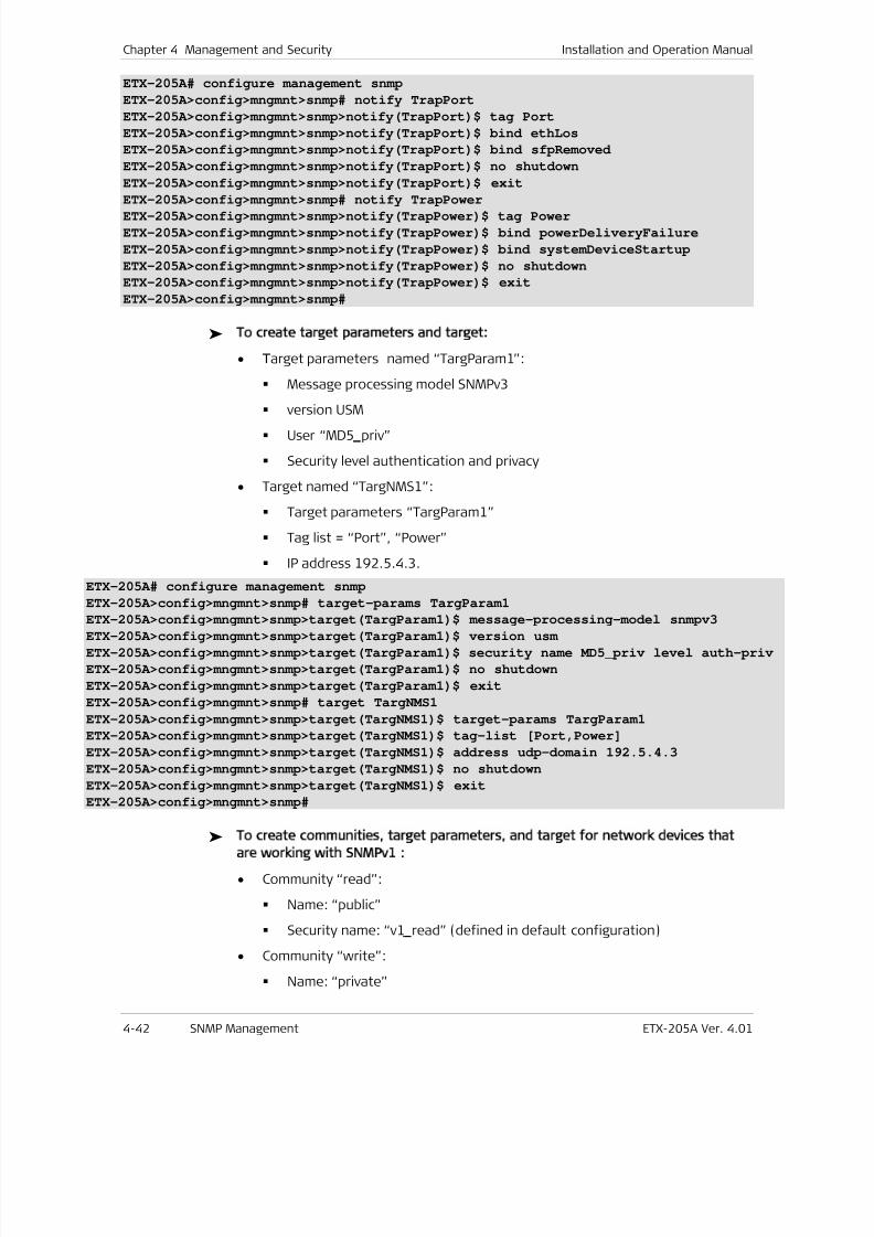
7/25/2019 Manual ETX-205A
http://slidepdf.com/reader/full/manual-etx-205a 110/409
Chapter 4 Management and Security Installation and Operation Manual
4-42 SNMP Management ETX-205A Ver. 4.01
ETX-205A# configure management snmp
ETX-205A>config>mngmnt>snmp# notify TrapPort
ETX-205A>config>mngmnt>snmp>notify(TrapPort)$ tag Port
ETX-205A>config>mngmnt>snmp>notify(TrapPort)$ bind ethLos
ETX-205A>config>mngmnt>snmp>notify(TrapPort)$ bind sfpRemoved
ETX-205A>config>mngmnt>snmp>notify(TrapPort)$ no shutdown
ETX-205A>config>mngmnt>snmp>notify(TrapPort)$ exit
ETX-205A>config>mngmnt>snmp# notify TrapPowerETX-205A>config>mngmnt>snmp>notify(TrapPower)$ tag Power
ETX-205A>config>mngmnt>snmp>notify(TrapPower)$ bind powerDeliveryFailure
ETX-205A>config>mngmnt>snmp>notify(TrapPower)$ bind systemDeviceStartup
ETX-205A>config>mngmnt>snmp>notify(TrapPower)$ no shutdown
ETX-205A>config>mngmnt>snmp>notify(TrapPower)$ exit
ETX-205A>config>mngmnt>snmp#
To create target parameters and target:
• Target parameters named “TargParam1”:
Message processing model SNMPv3
version USM
User “MD5 priv”
Security level authentication and privacy
• Target named “TargNMS1”:
Target parameters “TargParam1”
Tag list = “Port”, “Power”
IP address 192.5.4.3.
ETX-205A# configure management snmp
ETX-205A>config>mngmnt>snmp# target-params TargParam1
ETX-205A>config>mngmnt>snmp>target(TargParam1)$ message-processing-model snmpv3ETX-205A>config>mngmnt>snmp>target(TargParam1)$ version usm
ETX-205A>config>mngmnt>snmp>target(TargParam1)$ security name MD5_priv level auth-priv
ETX-205A>config>mngmnt>snmp>target(TargParam1)$ no shutdown
ETX-205A>config>mngmnt>snmp>target(TargParam1)$ exit
ETX-205A>config>mngmnt>snmp# target TargNMS1
ETX-205A>config>mngmnt>snmp>target(TargNMS1)$ target-params TargParam1
ETX-205A>config>mngmnt>snmp>target(TargNMS1)$ tag-list [Port,Power]
ETX-205A>config>mngmnt>snmp>target(TargNMS1)$ address udp-domain 192.5.4.3
ETX-205A>config>mngmnt>snmp>target(TargNMS1)$ no shutdown
ETX-205A>config>mngmnt>snmp>target(TargNMS1)$ exit
ETX-205A>config>mngmnt>snmp#
To create communities, target parameters, and target for network devices that
are working with SNMPv1 :
• Community “read”:
Name: “public”
Security name: “v1 read” (defined in default configuration)
• Community “write”:
Name: “private”
7/25/2019 Manual ETX-205A
http://slidepdf.com/reader/full/manual-etx-205a 111/409
Installation and Operation Manual Chapter 4 Management and Security
ETX-205A Ver. 4.01 SNMP Management 4-43
Security name: “v1 write” (defined in default configuration)
• Community “trap”:
Name: “public”
Security name: “v1 trap” (defined in default configuration)
• Target parameters named “snv1”:
Message processing model SNMPv1
Version SNMPv1
Security name: “v1 trap”
Security: level no authentication and no privacy
• Target named “NMSsnmpv1”:
Target parameters “snv1”
Tag list = “unmasked”
IP address 192.5.6.7.
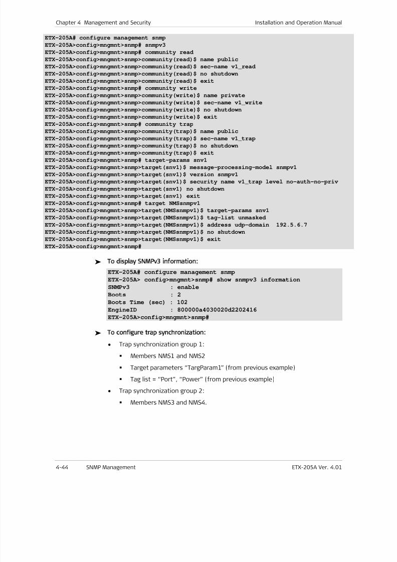
7/25/2019 Manual ETX-205A
http://slidepdf.com/reader/full/manual-etx-205a 112/409
Chapter 4 Management and Security Installation and Operation Manual
4-44 SNMP Management ETX-205A Ver. 4.01
ETX-205A# configure management snmp
ETX-205A>config>mngmnt>snmp# snmpv3
ETX-205A>config>mngmnt>snmp# community read
ETX-205A>config>mngmnt>snmp>community(read)$ name public
ETX-205A>config>mngmnt>snmp>community(read)$ sec-name v1_read
ETX-205A>config>mngmnt>snmp>community(read)$ no shutdown
ETX-205A>config>mngmnt>snmp>community(read)$ exit
ETX-205A>config>mngmnt>snmp# community write
ETX-205A>config>mngmnt>snmp>community(write)$ name private
ETX-205A>config>mngmnt>snmp>community(write)$ sec-name v1_write
ETX-205A>config>mngmnt>snmp>community(write)$ no shutdown
ETX-205A>config>mngmnt>snmp>community(write)$ exit
ETX-205A>config>mngmnt>snmp# community trap
ETX-205A>config>mngmnt>snmp>community(trap)$ name public
ETX-205A>config>mngmnt>snmp>community(trap)$ sec-name v1_trap
ETX-205A>config>mngmnt>snmp>community(trap)$ no shutdown
ETX-205A>config>mngmnt>snmp>community(trap)$ exit
ETX-205A>config>mngmnt>snmp# target-params snv1
ETX-205A>config>mngmnt>snmp>target(snv1)$ message-processing-model snmpv1
ETX-205A>config>mngmnt>snmp>target(snv1)$ version snmpv1
ETX-205A>config>mngmnt>snmp>target(snv1)$ security name v1_trap level no-auth-no-priv
ETX-205A>config>mngmnt>snmp>target(snv1) no shutdown
ETX-205A>config>mngmnt>snmp>target(snv1) exit
ETX-205A>config>mngmnt>snmp# target NMSsnmpv1
ETX-205A>config>mngmnt>snmp>target(NMSsnmpv1)$ target-params snv1
ETX-205A>config>mngmnt>snmp>target(NMSsnmpv1)$ tag-list unmasked
ETX-205A>config>mngmnt>snmp>target(NMSsnmpv1)$ address udp-domain 192.5.6.7
ETX-205A>config>mngmnt>snmp>target(NMSsnmpv1)$ no shutdown
ETX-205A>config>mngmnt>snmp>target(NMSsnmpv1)$ exit
ETX-205A>config>mngmnt>snmp#
To display SNMPv3 information:
ETX-205A# configure management snmp
ETX-205A> config>mngmnt>snmp# show snmpv3 informationSNMPv3 : enable
Boots : 2
Boots Time (sec) : 102
EngineID : 800000a4030020d2202416
ETX-205A>config>mngmnt>snmp#
To configure trap synchronization:
• Trap synchronization group 1:
Members NMS1 and NMS2
Target parameters “TargParam1” (from previous example)
Tag list = “Port”, “Power” (from previous example)
• Trap synchronization group 2:
Members NMS3 and NMS4.
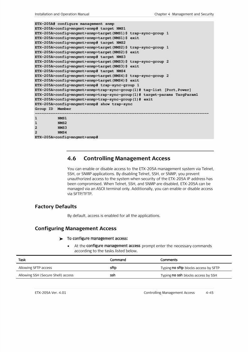
7/25/2019 Manual ETX-205A
http://slidepdf.com/reader/full/manual-etx-205a 113/409
Installation and Operation Manual Chapter 4 Management and Security
ETX-205A Ver. 4.01 Controlling Management Access 4-45
ETX-205A# configure management snmp
ETX-205A>config>mngmnt>snmp# target NMS1
ETX-205A>config>mngmnt>snmp>target(NMS1)$ trap-sync-group 1
ETX-205A>config>mngmnt>snmp>target(NMS1)$ exit
ETX-205A>config>mngmnt>snmp# target NMS2
ETX-205A>config>mngmnt>snmp>target(NMS2)$ trap-sync-group 1
ETX-205A>config>mngmnt>snmp>target(NMS2)$ exit
ETX-205A>config>mngmnt>snmp# target NMS3ETX-205A>config>mngmnt>snmp>target(NMS3)$ trap-sync-group 2
ETX-205A>config>mngmnt>snmp>target(NMS3)$ exit
ETX-205A>config>mngmnt>snmp# target NMS4
ETX-205A>config>mngmnt>snmp>target(NMS4)$ trap-sync-group 2
ETX-205A>config>mngmnt>snmp>target(NMS4)$ exit
ETX-205A>config>mngmnt>snmp# trap-sync-group 1
ETX-205A>config>mngmnt>snmp>trap-sync-group(1)# tag-list [Port,Power]
ETX-205A>config>mngmnt>snmp>trap-sync-group(1)# target-params TargParam1
ETX-205A>config>mngmnt>snmp>trap-sync-group(1)# exit
ETX-205A>config>mngmnt>snmp# show trap-sync
Group ID Member
-----------------------------------------------------------------------------
1 NMS11 NMS2
2 NMS3
2 NMS4
ETX-205A>config>mngmnt>snmp#
4.6 Controlling Management Access
You can enable or disable access to the ETX-205A management system via Telnet,
SSH, or SNMP applications. By disabling Telnet, SSH, or SNMP, you preventunauthorized access to the system when security of the ETX-205A IP address has
been compromised. When Telnet, SSH, and SNMP are disabled, ETX-205A can be
managed via an ASCII terminal only. Additionally, you can enable or disable access
via SFTP/TFTP.
Factory Defaults
By default, access is enabled for all the applications.
Configuring Management Access
To configure management access:
• At the configure management access prompt enter the necessary commands
according to the tasks listed below.
Task Command Comments
Allowing SFTP accesssftp Typing no sftp blocks access by SFTP
Allowing SSH (Secure Shell) accessssh
Typingno ssh
blocks access by SSH
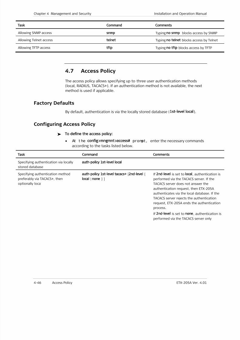
7/25/2019 Manual ETX-205A
http://slidepdf.com/reader/full/manual-etx-205a 114/409
Chapter 4 Management and Security Installation and Operation Manual
4-46 Access Policy ETX-205A Ver. 4.01
Task Command Comments
Allowing SNMP accesssnmp
Typingno snmp
blocks access by SNMP
Allowing Telnet accesstelnet
Typingno telnet
blocks access by Telnet
Allowing TFTP accesstftp
Typingno tftp
blocks access by TFTP
4.7 Access Policy
The access policy allows specifying up to three user authentication methods
(local, RADIUS, TACACS+). If an authentication method is not available, the next
method is used if applicable.
Factory Defaults
By default, authentication is via the locally stored database (1st-level local).
Configuring Access Policy
To define the access policy:
• At t he config>mngmnt>access prompt , enter the necessary commands
according to the tasks listed below.
Task Command Comments
Specifying authentication via locally
stored database
auth-policy 1st-level local
Specifying authentication method
preferably via TACACS+, then
optionally local
auth-policy 1st-level tacacs+
[2nd-level
local | none ]
If2nd-level
is set tolocal
, authentication is
performed via the TACACS server. If the
TACACS server does not answer the
authentication request, then ETX-205A
authenticates via the local database. If the
TACACS server rejects the authentication
request, ETX-205A ends the authentication
process.
If2nd-level
is set tonone
, authentication
performed via the TACACS server only
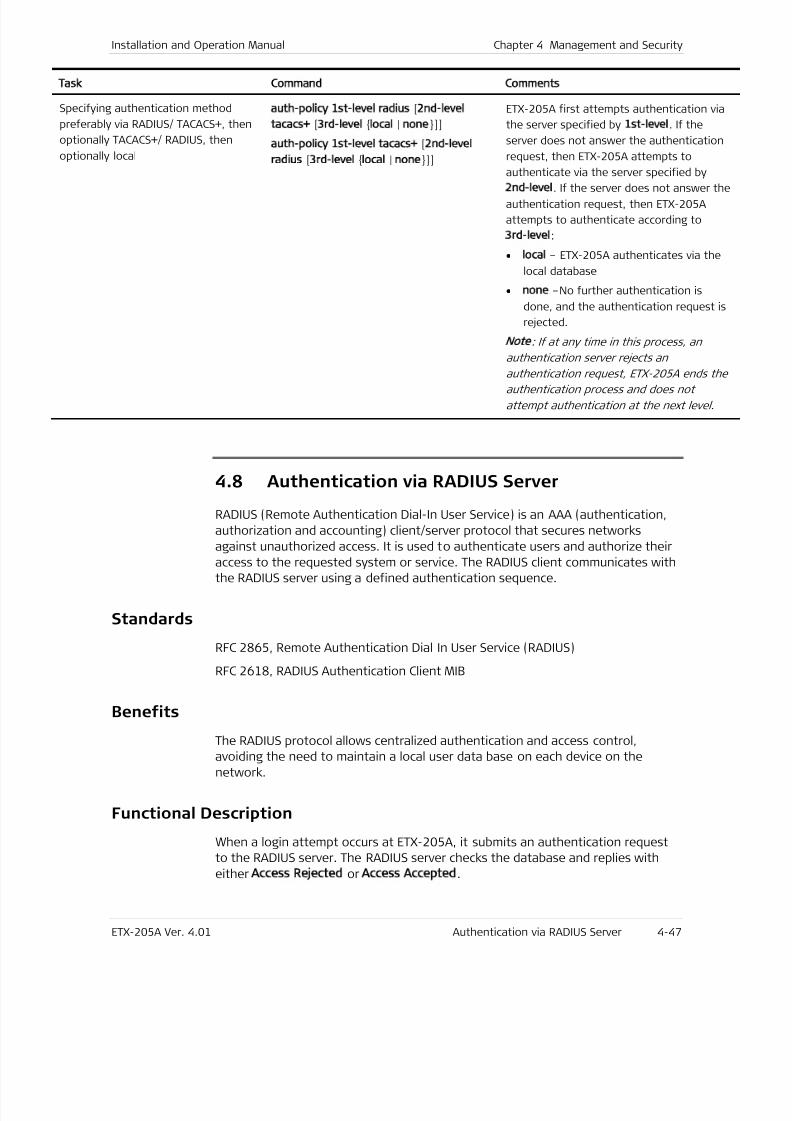
7/25/2019 Manual ETX-205A
http://slidepdf.com/reader/full/manual-etx-205a 115/409
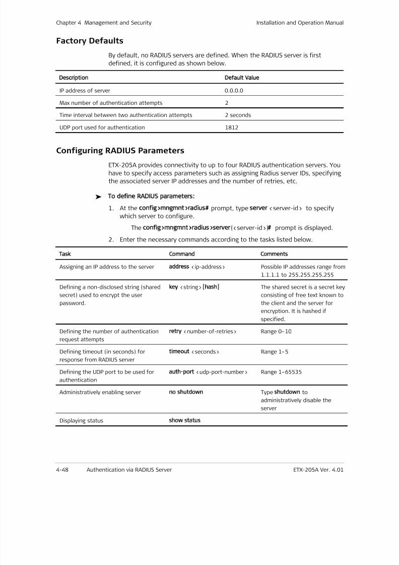
7/25/2019 Manual ETX-205A
http://slidepdf.com/reader/full/manual-etx-205a 116/409
Chapter 4 Management and Security Installation and Operation Manual
4-48 Authentication via RADIUS Server ETX-205A Ver. 4.01
Factory Defaults
By default, no RADIUS servers are defined. When the RADIUS server is first
defined, it is configured as shown below.
Description Default Value
IP address of server 0.0.0.0
Max number of authentication attempts 2
Time interval between two authentication attempts 2 seconds
UDP port used for authentication 1812
Configuring RADIUS Parameters
ETX-205A provides connectivity to up to four RADIUS authentication servers. You
have to specify access parameters such as assigning Radius server IDs, specifying
the associated server IP addresses and the number of retries, etc.
To define RADIUS parameters:
1. At the config>mngmnt>radius prompt, type server <server-id> to specify
which server to configure.
The config>mngmnt>radius>server(<server-id>) prompt is displayed.
2. Enter the necessary commands according to the tasks listed below.
Task Command Comments
Assigning an IP address to the server address <ip-address> Possible IP addresses range from
1.1.1.1 to 255.255.255.255
Defining a non-disclosed string (shared
secret) used to encrypt the user
password.
key
<string> [hash]
The shared secret is a secret key
consisting of free text known to
the client and the server for
encryption. It is hashed if
specified.
Defining the number of authentication
request attempts
retry <number-of-retries> Range 0–10
Defining timeout (in seconds) for
response from RADIUS server
timeout <seconds> Range 1–5
Defining the UDP port to be used for
authentication
auth-port <udp-port-number> Range 1–65535
Administratively enabling serverno shutdown
Type shutdown
to
administratively disable the
server
Displaying status show status
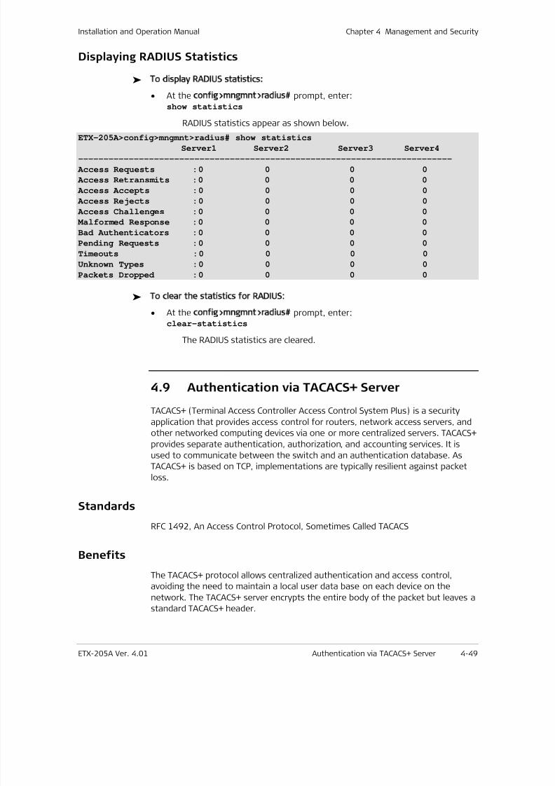
7/25/2019 Manual ETX-205A
http://slidepdf.com/reader/full/manual-etx-205a 117/409
Installation and Operation Manual Chapter 4 Management and Security
ETX-205A Ver. 4.01 Authentication via TACACS+ Server 4-49
Displaying RADIUS Statistics
To display RADIUS statistics:
• At the config>mngmnt>radius prompt, enter:show statistics
RADIUS statistics appear as shown below.
ETX-205A>config>mngmnt>radius# show statistics
Server1 Server2 Server3 Server4
--------------------------------------------------------------------------
Access Requests : 0 0 0 0
Access Retransmits : 0 0 0 0
Access Accepts : 0 0 0 0
Access Rejects : 0 0 0 0
Access Challenges : 0 0 0 0
Malformed Response : 0 0 0 0
Bad Authenticators : 0 0 0 0
Pending Requests : 0 0 0 0
Timeouts : 0 0 0 0
Unknown Types : 0 0 0 0
Packets Dropped : 0 0 0 0
To clear the statistics for RADIUS:
• At the config>mngmnt>radius prompt, enter:clear-statistics
The RADIUS statistics are cleared.
4.9
Authentication via TACACS+ ServerTACACS+ (Terminal Access Controller Access Control System Plus) is a security
application that provides access control for routers, network access servers, and
other networked computing devices via one or more centralized servers. TACACS+
provides separate authentication, authorization, and accounting services. It is
used to communicate between the switch and an authentication database. As
TACACS+ is based on TCP, implementations are typically resilient against packet
loss.
Standards
RFC 1492, An Access Control Protocol, Sometimes Called TACACS
Benefits
The TACACS+ protocol allows centralized authentication and access control,
avoiding the need to maintain a local user data base on each device on the
network. The TACACS+ server encrypts the entire body of the packet but leaves a
standard TACACS+ header.

7/25/2019 Manual ETX-205A
http://slidepdf.com/reader/full/manual-etx-205a 118/409
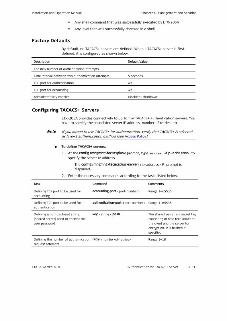
7/25/2019 Manual ETX-205A
http://slidepdf.com/reader/full/manual-etx-205a 119/409
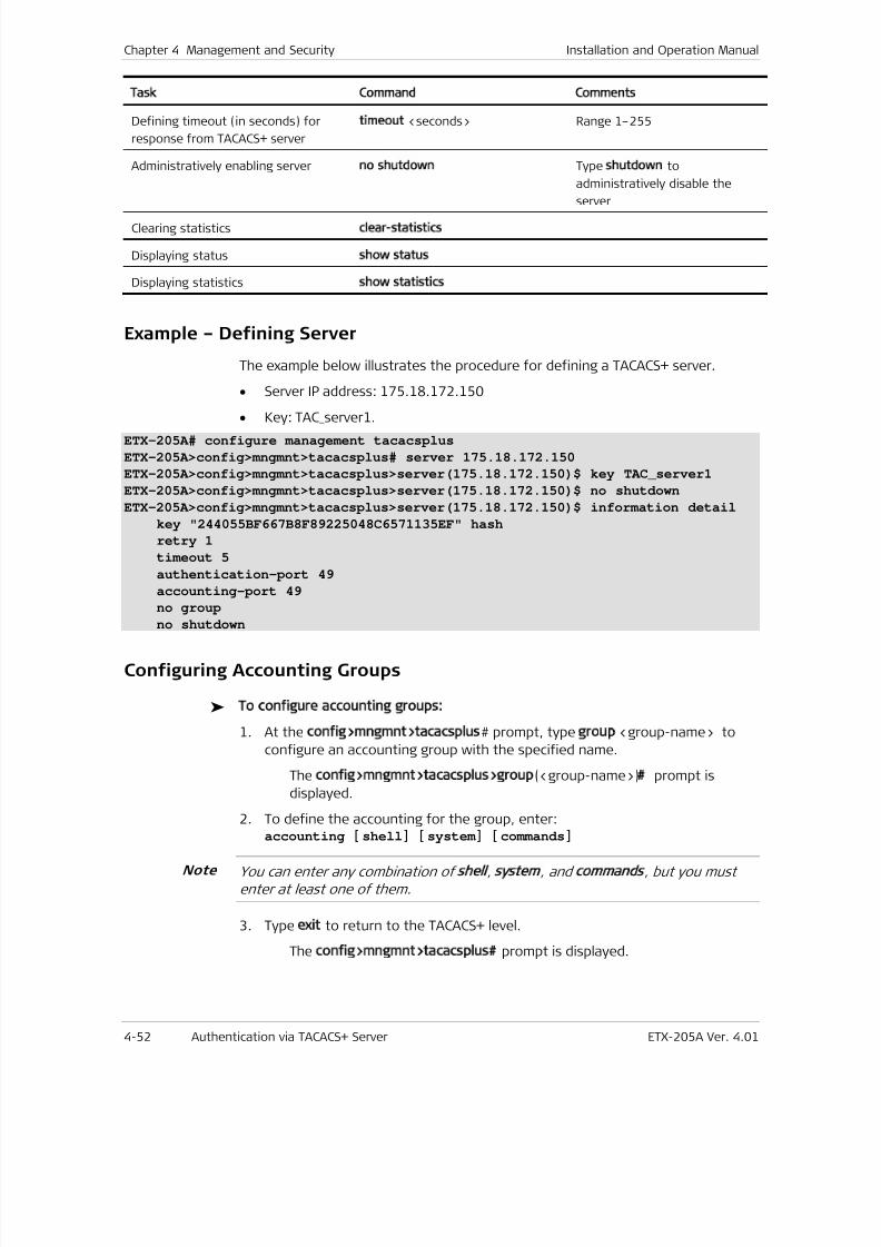
7/25/2019 Manual ETX-205A
http://slidepdf.com/reader/full/manual-etx-205a 120/409
Chapter 4 Management and Security Installation and Operation Manual
4-52 Authentication via TACACS+ Server ETX-205A Ver. 4.01
Task Command Comments
Defining timeout (in seconds) for
response from TACACS+ server
timeout
<seconds> Range 1–255
Administratively enabling serverno shutdown
Type shutdown
to
administratively disable the
server
Clearing statistics clear-statistics
Displaying status show status
Displaying statisticsshow statistics
Example – Defining Server
The example below illustrates the procedure for defining a TACACS+ server.
• Server IP address: 175.18.172.150
• Key: TAC_server1.
ETX-205A# configure management tacacsplus
ETX-205A>config>mngmnt>tacacsplus# server 175.18.172.150
ETX-205A>config>mngmnt>tacacsplus>server(175.18.172.150)$ key TAC_server1
ETX-205A>config>mngmnt>tacacsplus>server(175.18.172.150)$ no shutdown
ETX-205A>config>mngmnt>tacacsplus>server(175.18.172.150)$ information detail
key "244055BF667B8F89225048C6571135EF" hash
retry 1
timeout 5
authentication-port 49
accounting-port 49
no group
no shutdown
Configuring Accounting Groups
To configure accounting groups:
1. At the config>mngmnt>tacacsplus# prompt, type group <group-name> to
configure an accounting group with the specified name.
The config>mngmnt>tacacsplus>group(<group-name>) prompt is
displayed.
2. To define the accounting for the group, enter:accounting [ shell] [ system ] [ commands]
You can enter any combination of shell, system , and commands, but you must
enter at least one of them.
3. Type exit to return to the TACACS+ level.
The config>mngmnt>tacacsplus prompt is displayed.
Note
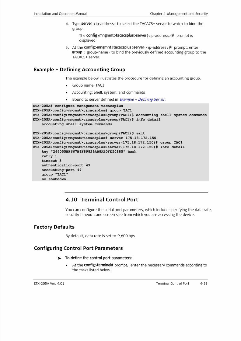
7/25/2019 Manual ETX-205A
http://slidepdf.com/reader/full/manual-etx-205a 121/409
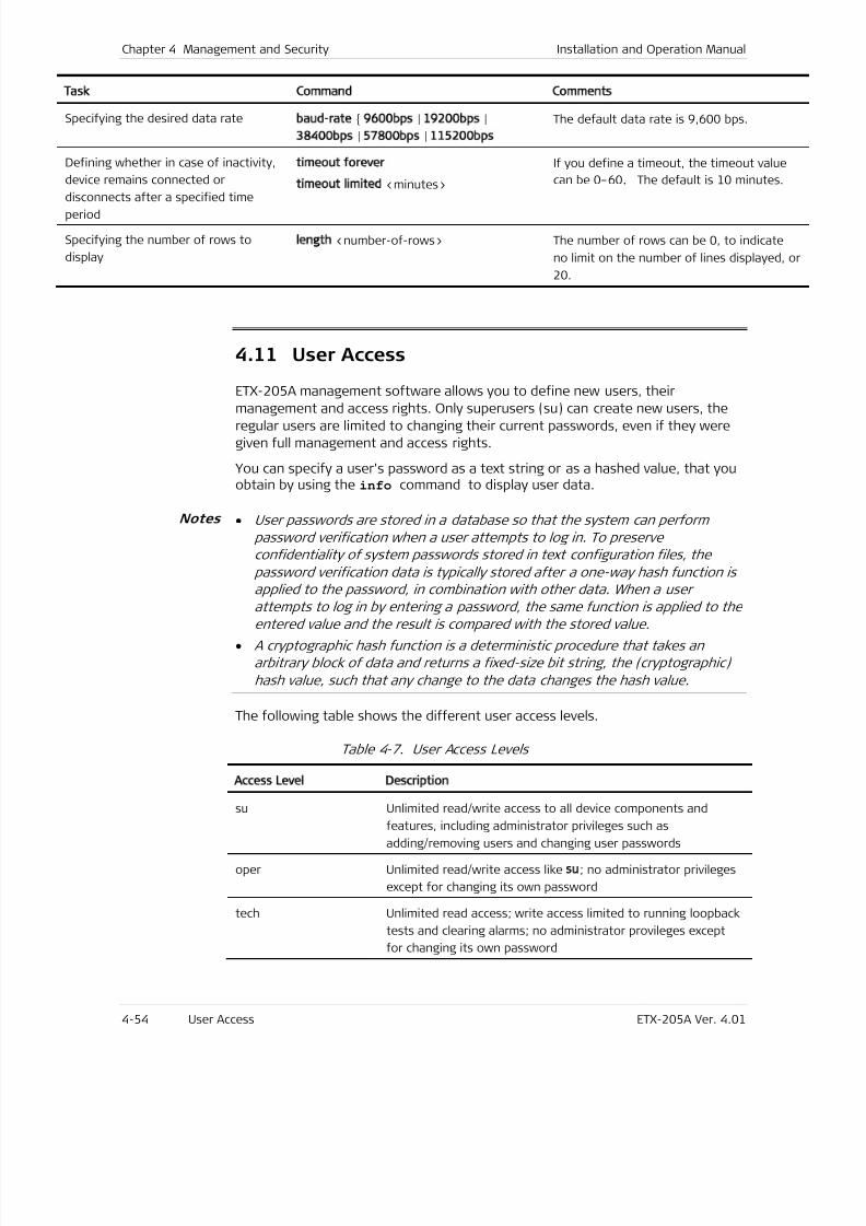
7/25/2019 Manual ETX-205A
http://slidepdf.com/reader/full/manual-etx-205a 122/409
Chapter 4 Management and Security Installation and Operation Manual
4-54 User Access ETX-205A Ver. 4.01
Task Command Comments
Specifying the desired data ratebaud-rate
9600bps
|19200bps
|
38400bps
|57800bps
| 115200bps
The default data rate is 9,600 bps.
Defining whether in case of inactivity,
device remains connected or
disconnects after a specified timeperiod
timeout forever
timeout limited <minutes>
If you define a timeout, the timeout value
can be 0–60. The default is 10 minutes.
Specifying the number of rows to
display
length
<number-of-rows>
The number of rows can be 0, to indicate
no limit on the number of lines displayed, o
20.
4.11 User Access
ETX-205A management software allows you to define new users, their
management and access rights. Only superusers (su) can create new users, theregular users are limited to changing their current passwords, even if they were
given full management and access rights.
You can specify a user’s password as a text string or as a hashed value, that youobtain by using the info command to display user data.
• User passwords are stored in a database so that the system can perform
password verification when a user attempts to log in. To preserve
confidentiality of system passwords stored in text configuration files, the
password verification data is typically stored after a one-way hash function is
applied to the password, in combination with other data. When a user
attempts to log in by entering a password, the same function is applied to theentered value and the result is compared with the stored value.
• A cryptographic hash function is a deterministic procedure that takes an
arbitrary block of data and returns a fixed-size bit string, the (cryptographic)
hash value, such that any change to the data changes the hash value.
The following table shows the different user access levels.
Table 4-7. User Access Levels
Access Level Description
su Unlimited read/write access to all device components and
features, including administrator privileges such as
adding/removing users and changing user passwords
oper Unlimited read/write access like su; no administrator privileges
except for changing its own password
tech Unlimited read access; write access limited to running loopback
tests and clearing alarms; no administrator provileges except
for changing its own password
Notes

7/25/2019 Manual ETX-205A
http://slidepdf.com/reader/full/manual-etx-205a 123/409
Installation and Operation Manual Chapter 4 Management and Security
ETX-205A Ver. 4.01 User Access 4-55
Access Level Description
user Unlimited read access; no write access; no administrator
provileges except for changing its own password
Factory Defaults
By default, the following users exist in the device.
Table 4-8. Default Users
User Name Access Level Password
su su 1234
oper oper 1234
tech tech 1234
user user 1234
Configuring Users
To add a new user:
1. Make sure that you are logged on as superuser (su).
2. Navigate to the Management context (config>mngmnt).
3. Define a new user:
user <name> [ level su | oper | tech | user ]
[ password <passwor d> [ hash] ]
Example – Defining Users
To define a new user:
• User name = staff
• User password = 1234.
ETX-205A# configure management
ETX-205A>config>mngmnt# user staff level su password 1234
# Password is encrypted successfully
ETX-205A>config>mngmnt#
To add a new user with a hashed password:
1. Define a new user with a text password.
2. Use info detail to display the password hash value.
3. Define another user with the hashed password from the info output.
The second user can log in with the text password defined in step 1.
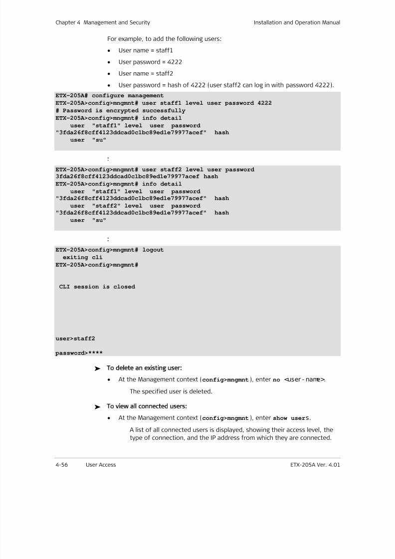
7/25/2019 Manual ETX-205A
http://slidepdf.com/reader/full/manual-etx-205a 124/409
Chapter 4 Management and Security Installation and Operation Manual
4-56 User Access ETX-205A Ver. 4.01
For example, to add the following users:
• User name = staff1
• User password = 4222
• User name = staff2
• User password = hash of 4222 (user staff2 can log in with password 4222).
ETX-205A# configure management
ETX-205A>config>mngmnt# user staff1 level user password 4222
# Password is encrypted successfully
ETX-205A>config>mngmnt# info detail
user "staff1" level user password
"3fda26f8cff4123ddcad0c1bc89ed1e79977acef" hash
user "su"
:
ETX-205A>config>mngmnt# user staff2 level user password3fda26f8cff4123ddcad0c1bc89ed1e79977acef hash
ETX-205A>config>mngmnt# info detailuser "staff1" level user password
"3fda26f8cff4123ddcad0c1bc89ed1e79977acef" hash
user "staff2" level user password
"3fda26f8cff4123ddcad0c1bc89ed1e79977acef" hash
user "su"
:
ETX-205A>config>mngmnt# logout
exiting cli
ETX-205A>config>mngmnt#
CLI session is closed
user>staff2
password>****
To delete an existing user:
• At the Management context (config>mngmnt), enter no <user - name>.
The specified user is deleted.
To view all connected users:
• At the Management context (config>mngmnt), enter show users.
A list of all connected users is displayed, showing their access level, the
type of connection, and the IP address from which they are connected.

7/25/2019 Manual ETX-205A
http://slidepdf.com/reader/full/manual-etx-205a 125/409

7/25/2019 Manual ETX-205A
http://slidepdf.com/reader/full/manual-etx-205a 126/409
Chapter 4 Management and Security Installation and Operation Manual
4-58 User Access ETX-205A Ver. 4.01
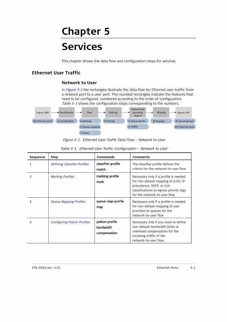
7/25/2019 Manual ETX-205A
http://slidepdf.com/reader/full/manual-etx-205a 127/409
ETX-205A Ver. 4.01 Ethernet Ports 5-1
Chapter 5
Services
This chapter shows the data flow and configuration steps for services.
Ethernet User Traffic
Network to User
In Figure 5-1 the rectangles illustrate the data flow for Ethernet user traffic from
a network port to a user port. The rounded rectangles indicate the features that
need to be configured, numbered according to the order of configuration.
Table 5-1 shows the configuration steps corresponding to the numbers.
Figure 5-1. Ethernet User Traffic Data Flow – Network to User
Table 5-1. Ethernet User Traffic Configuration – Network to User
Sequence Step Commands Comments
1 Defining Classifier Profiles classifier-profile
match
The classifier profile defines the
criteria for the network-to-user flow
2 Marking Profiles marking-profile
mark
Necessary only if a profile is needed
for non-default mapping of p-bit, IP
precedence, DSCP, or CoS
classifications to egress priority tags
for the network-to-user flow
3 Queue Mapping Profiles queue-map-profile
map
Necessary only if a profile is needed
for non-default mapping of user
priorities to queues for the
network-to-user flow
4 Configuring Policer Profiles policer-profile
bandwidth
compensation
Necessary only if you need to define
non-default bandwidth limits or
overhead compensation for the
incoming traffic of the
network-to-user flow
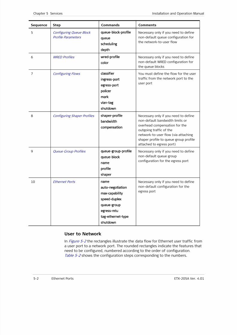
7/25/2019 Manual ETX-205A
http://slidepdf.com/reader/full/manual-etx-205a 128/409
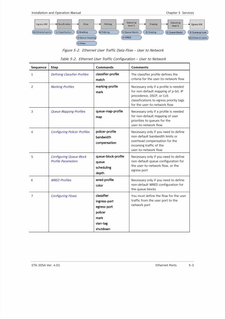
7/25/2019 Manual ETX-205A
http://slidepdf.com/reader/full/manual-etx-205a 129/409
Installation and Operation Manual Chapter 5 Services
ETX-205A Ver. 4.01 Ethernet Ports 5-3
Figure 5-2. Ethernet User Traffic Data Flow – User to Network
Table 5-2. Ethernet User Traffic Configuration – User to Network
Sequence Step Commands Comments
1 Defining Classifier Profiles classifier-profile
match
The classifier profile defines the
criteria for the user-to-network flow
2 Marking Profiles marking-profile
mark
Necessary only if a profile is needed
for non-default mapping of p-bit, IP
precedence, DSCP, or CoS
classifications to egress priority tags
for the user-to-network flow
3 Queue Mapping Profiles queue-map-profile
map
Necessary only if a profile is needed
for non-default mapping of user
priorities to queues for the
user-to-network flow
4 Configuring Policer Profiles policer-profile
bandwidth
compensation
Necessary only if you need to define
non-default bandwidth limits or
overhead compensation for the
incoming traffic of the
user-to-network flow
5 Configuring Queue Block
Profile Parameters
queue-block-profile
queue
scheduling
depth
Necessary only if you need to define
non-default queue configuration for
the user-to-network flow, or the
egress port
6 WRED Profiles wred-profile
color
Necessary only if you need to define
non-default WRED configuration for
the queue blocks
7 Configuring Flows classifier
ingress-port
egress-port
policer
mark
vlan-tag
shutdown
You must define the flow for the user
traffic from the user port to the
network port
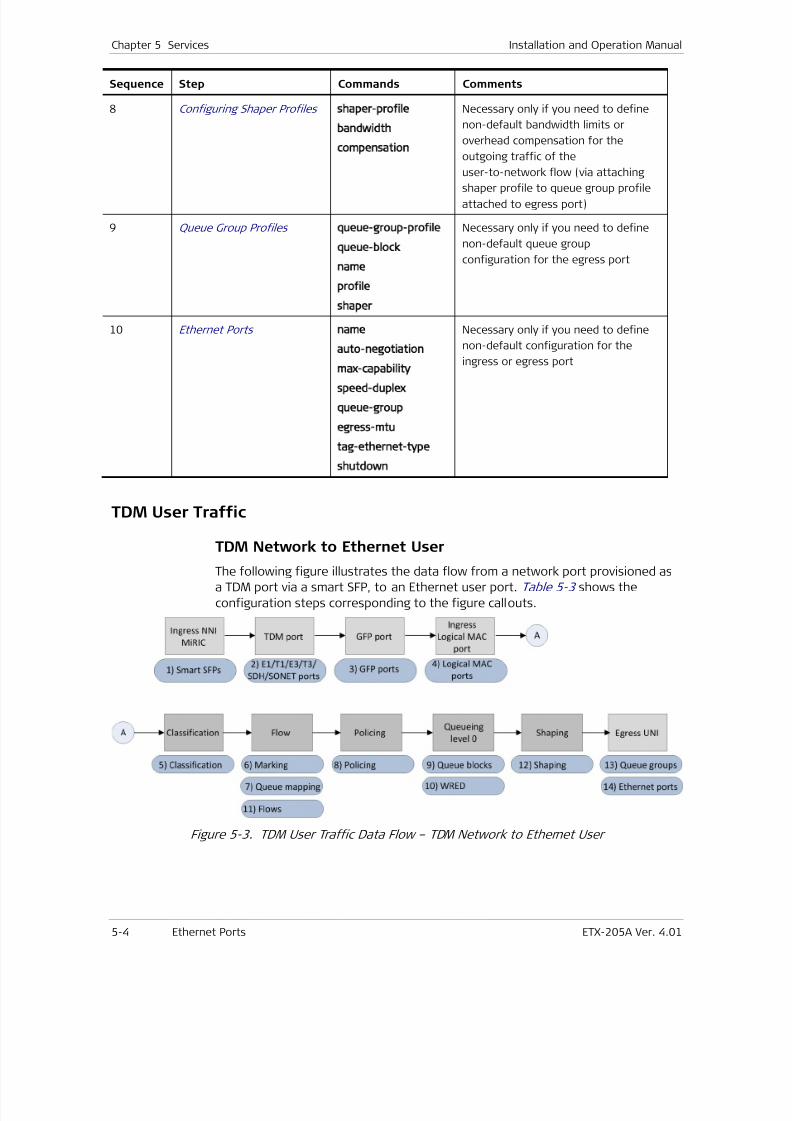
7/25/2019 Manual ETX-205A
http://slidepdf.com/reader/full/manual-etx-205a 130/409
Chapter 5 Services Installation and Operation Manual
5-4 Ethernet Ports ETX-205A Ver. 4.01
Sequence Step Commands Comments
8 Configuring Shaper Profiles shaper-profile
bandwidth
compensation
Necessary only if you need to define
non-default bandwidth limits or
overhead compensation for the
outgoing traffic of the
user-to-network flow (via attaching
shaper profile to queue group profileattached to egress port)
9 Queue Group Profiles queue-group-profile
queue-block
name
profile
shaper
Necessary only if you need to define
non-default queue group
configuration for the egress port
10 Ethernet Ports name
auto-negotiation
max-capability
speed-duplex
queue-group
egress-mtu
tag-ethernet-type
shutdown
Necessary only if you need to define
non-default configuration for the
ingress or egress port
TDM User Traffic
TDM Network to Ethernet User
The following figure illustrates the data flow from a network port provisioned as
a TDM port via a smart SFP, to an Ethernet user port. Table 5-3 shows the
configuration steps corresponding to the figure callouts.
Figure 5-3. TDM User Traffic Data Flow – TDM Network to Ethernet User
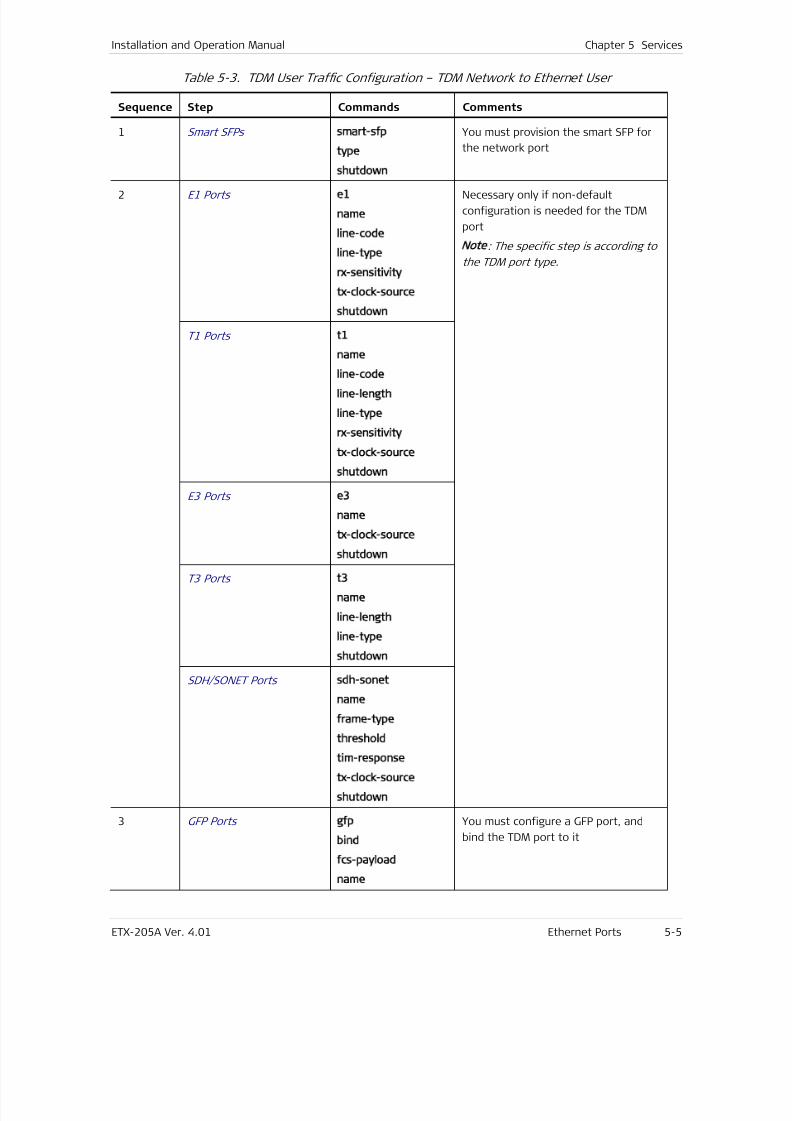
7/25/2019 Manual ETX-205A
http://slidepdf.com/reader/full/manual-etx-205a 131/409
Installation and Operation Manual Chapter 5 Services
ETX-205A Ver. 4.01 Ethernet Ports 5-5
Table 5-3. TDM User Traffic Configuration – TDM Network to Ethernet User
Sequence Step Commands Comments
1 Smart SFPs smart-sfp
type
shutdown
You must provision the smart SFP for
the network port
2 E1 Ports e1
name
line-code
line-type
rx-sensitivity
tx-clock-source
shutdown
Necessary only if non-default
configuration is needed for the TDM
port
Note: The specific step is according to
the TDM port type.
T1 Ports t1
name
line-code
line-length
line-type
rx-sensitivity
tx-clock-source
shutdown
E3 Ports e3
name
tx-clock-source
shutdown
T3 Ports t3
name
line-length
line-type
shutdown
SDH/SONET Ports sdh-sonet
name
frame-type
threshold
tim-response
tx-clock-source
shutdown
3 GFP Ports gfp
bind
fcs-payload
name
You must configure a GFP port, and
bind the TDM port to it
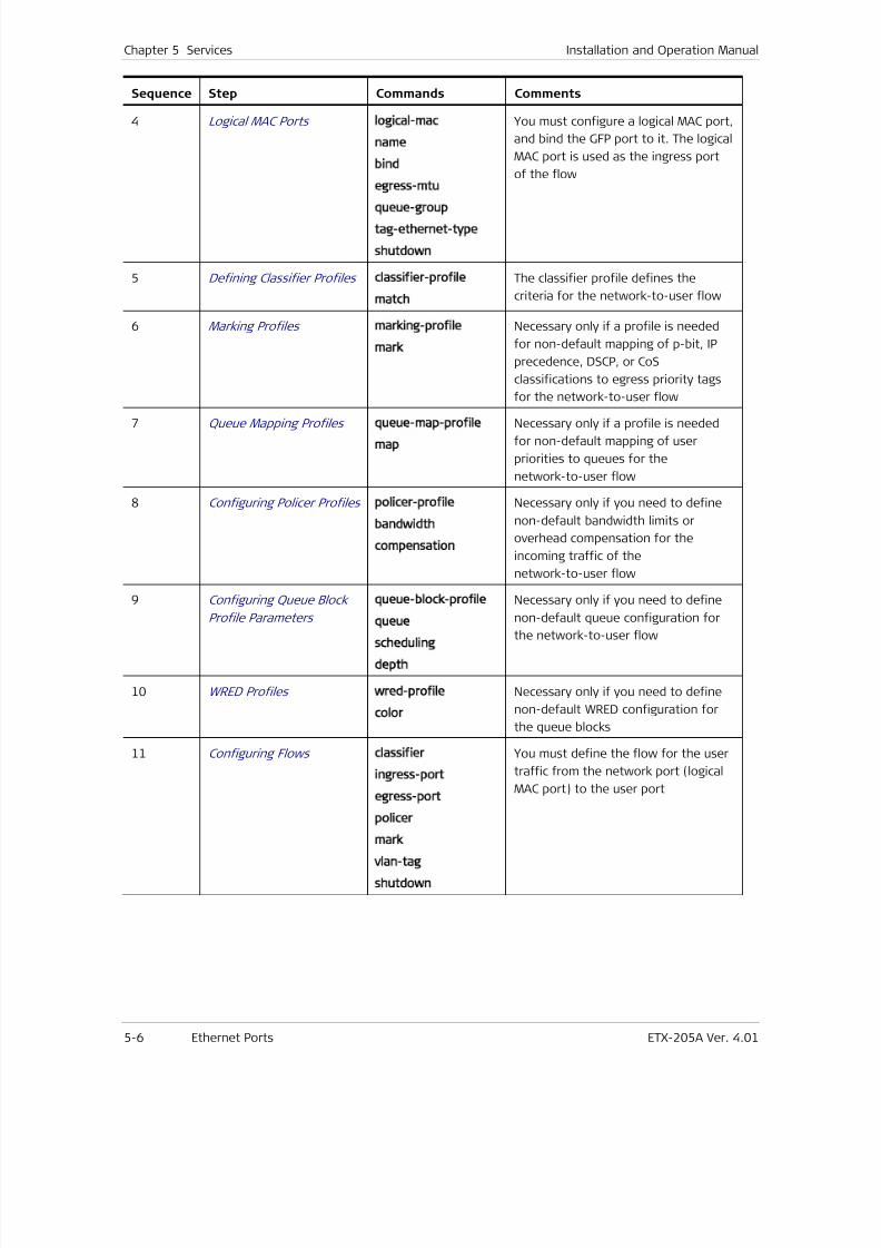
7/25/2019 Manual ETX-205A
http://slidepdf.com/reader/full/manual-etx-205a 132/409
Chapter 5 Services Installation and Operation Manual
5-6 Ethernet Ports ETX-205A Ver. 4.01
Sequence Step Commands Comments
4 Logical MAC Ports logical-mac
name
bind
egress-mtu
queue-group
tag-ethernet-type
shutdown
You must configure a logical MAC port,
and bind the GFP port to it. The logical
MAC port is used as the ingress port
of the flow
5 Defining Classifier Profiles classifier-profile
match
The classifier profile defines the
criteria for the network-to-user flow
6 Marking Profiles marking-profile
mark
Necessary only if a profile is needed
for non-default mapping of p-bit, IP
precedence, DSCP, or CoS
classifications to egress priority tags
for the network-to-user flow
7 Queue Mapping Profiles queue-map-profile
map
Necessary only if a profile is needed
for non-default mapping of user
priorities to queues for the
network-to-user flow
8 Configuring Policer Profiles policer-profile
bandwidth
compensation
Necessary only if you need to define
non-default bandwidth limits or
overhead compensation for the
incoming traffic of the
network-to-user flow
9 Configuring Queue Block
Profile Parameters
queue-block-profile
queue
scheduling
depth
Necessary only if you need to define
non-default queue configuration forthe network-to-user flow
10 WRED Profiles wred-profile
color
Necessary only if you need to define
non-default WRED configuration for
the queue blocks
11 Configuring Flows classifier
ingress-port
egress-port
policer
mark
vlan-tag
shutdown
You must define the flow for the user
traffic from the network port (logical
MAC port) to the user port
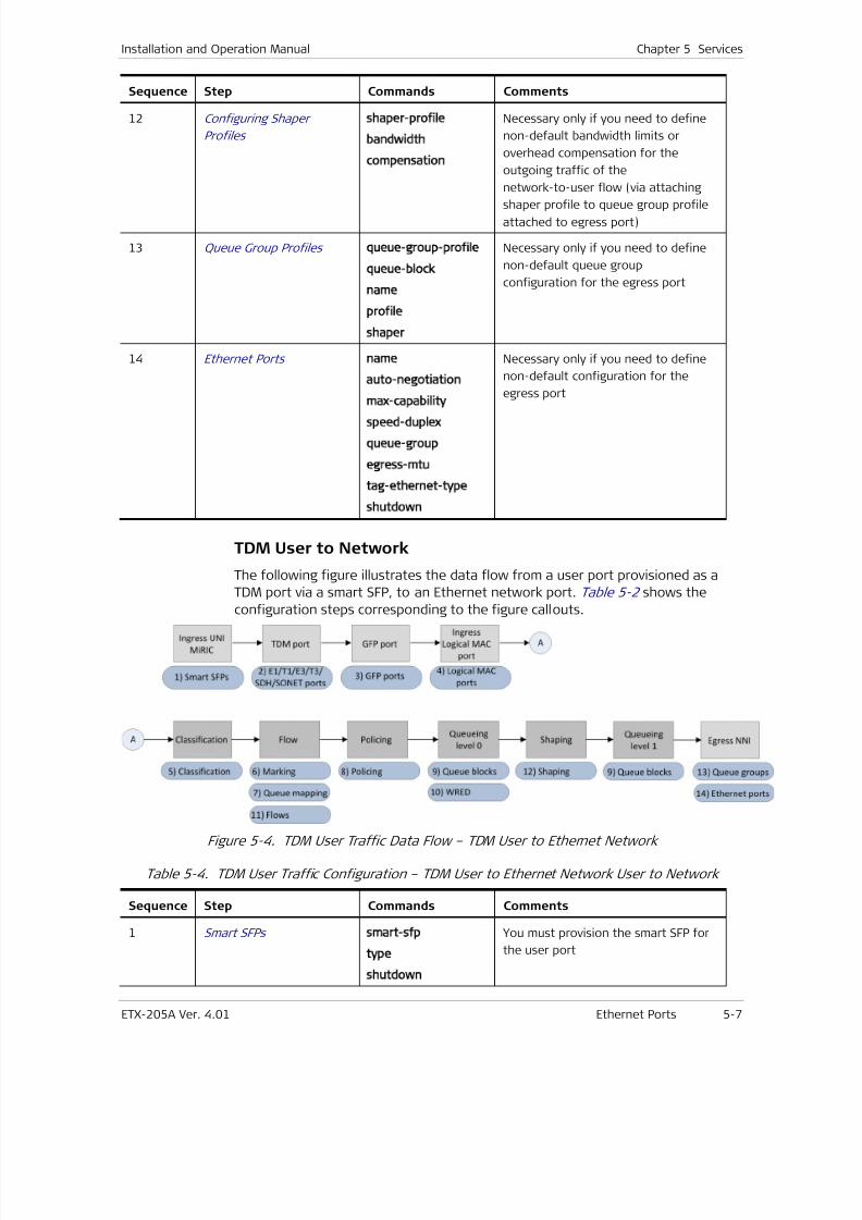
7/25/2019 Manual ETX-205A
http://slidepdf.com/reader/full/manual-etx-205a 133/409
Installation and Operation Manual Chapter 5 Services
ETX-205A Ver. 4.01 Ethernet Ports 5-7
Sequence Step Commands Comments
12 Configuring Shaper
Profiles
shaper-profile
bandwidth
compensation
Necessary only if you need to define
non-default bandwidth limits or
overhead compensation for the
outgoing traffic of the
network-to-user flow (via attaching
shaper profile to queue group profileattached to egress port)
13 Queue Group Profiles queue-group-profile
queue-block
name
profile
shaper
Necessary only if you need to define
non-default queue group
configuration for the egress port
14 Ethernet Ports name
auto-negotiation
max-capability
speed-duplex
queue-group
egress-mtu
tag-ethernet-type
shutdown
Necessary only if you need to define
non-default configuration for the
egress port
TDM User to Network
The following figure illustrates the data flow from a user port provisioned as a
TDM port via a smart SFP, to an Ethernet network port. Table 5-2 shows the
configuration steps corresponding to the figure callouts.
Figure 5-4. TDM User Traffic Data Flow – TDM User to Ethernet Network
Table 5-4. TDM User Traffic Configuration – TDM User to Ethernet Network User to Network
Sequence Step Commands Comments
1 Smart SFPs smart-sfp
type
shutdown
You must provision the smart SFP for
the user port
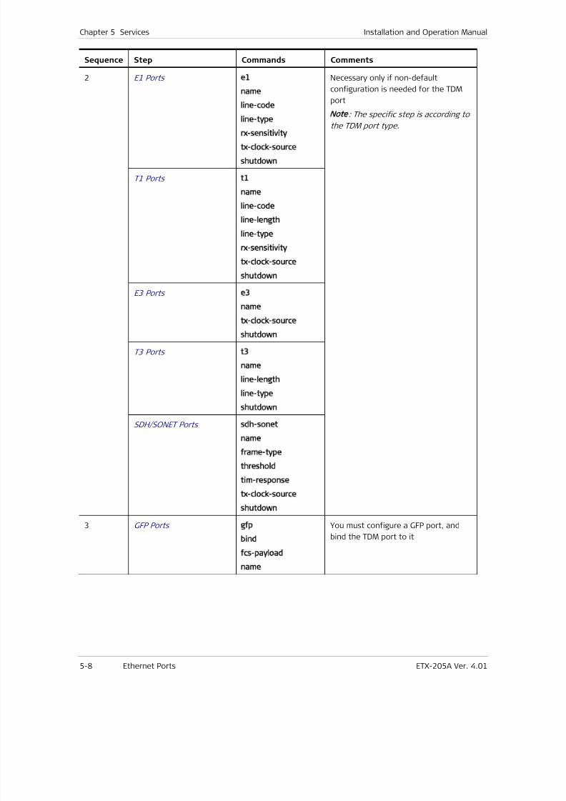
7/25/2019 Manual ETX-205A
http://slidepdf.com/reader/full/manual-etx-205a 134/409
Chapter 5 Services Installation and Operation Manual
5-8 Ethernet Ports ETX-205A Ver. 4.01
Sequence Step Commands Comments
2 E1 Ports e1
name
line-code
line-type
rx-sensitivity
tx-clock-source
shutdown
Necessary only if non-default
configuration is needed for the TDM
port
Note
: The specific step is according to
the TDM port type.
T1 Ports t1
name
line-code
line-length
line-type
rx-sensitivity
tx-clock-source
shutdown
E3 Ports e3
name
tx-clock-source
shutdown
T3 Ports t3
name
line-length
line-type
shutdown
SDH/SONET Ports sdh-sonet
name
frame-type
threshold
tim-response
tx-clock-source
shutdown
3 GFP Ports gfp
bind
fcs-payload
name
You must configure a GFP port, and
bind the TDM port to it
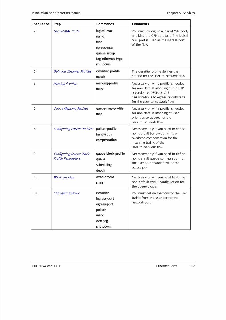
7/25/2019 Manual ETX-205A
http://slidepdf.com/reader/full/manual-etx-205a 135/409
Installation and Operation Manual Chapter 5 Services
ETX-205A Ver. 4.01 Ethernet Ports 5-9
Sequence Step Commands Comments
4 Logical MAC Ports logical-mac
name
bind
egress-mtu
queue-group
tag-ethernet-type
shutdown
You must configure a logical MAC port,
and bind the GFP port to it. The logical
MAC port is used as the ingress port
of the flow
5 Defining Classifier Profiles classifier-profile
match
The classifier profile defines the
criteria for the user-to-network flow
6 Marking Profiles marking-profile
mark
Necessary only if a profile is needed
for non-default mapping of p-bit, IP
precedence, DSCP, or CoS
classifications to egress priority tags
for the user-to-network flow
7 Queue Mapping Profiles queue-map-profile
map
Necessary only if a profile is needed
for non-default mapping of user
priorities to queues for the
user-to-network flow
8 Configuring Policer Profiles policer-profile
bandwidth
compensation
Necessary only if you need to define
non-default bandwidth limits or
overhead compensation for the
incoming traffic of the
user-to-network flow
9 Configuring Queue Block
Profile Parameters
queue-block-profile
queue
scheduling
depth
Necessary only if you need to define
non-default queue configuration forthe user-to-network flow, or the
egress port
10 WRED Profiles wred-profile
color
Necessary only if you need to define
non-default WRED configuration for
the queue blocks
11 Configuring Flows classifier
ingress-port
egress-port
policer
mark
vlan-tag
shutdown
You must define the flow for the user
traffic from the user port to the
network port
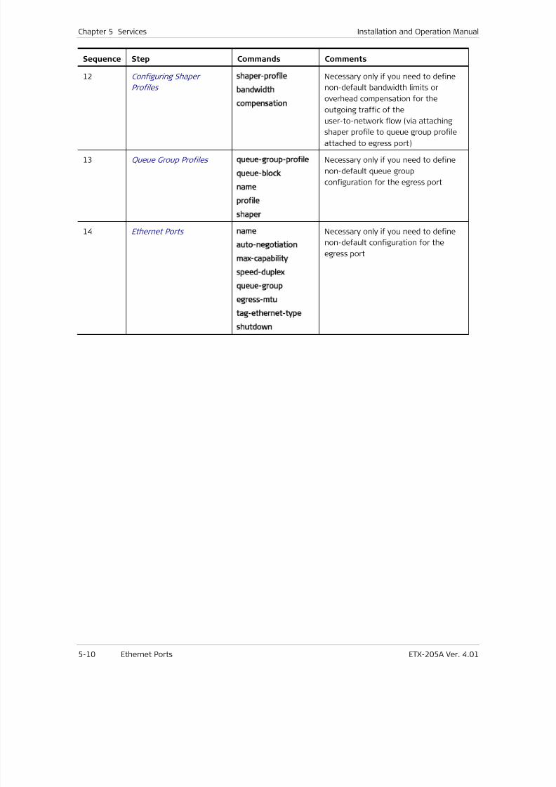
7/25/2019 Manual ETX-205A
http://slidepdf.com/reader/full/manual-etx-205a 136/409
Chapter 5 Services Installation and Operation Manual
5-10 Ethernet Ports ETX-205A Ver. 4.01
Sequence Step Commands Comments
12 Configuring Shaper
Profiles
shaper-profile
bandwidth
compensation
Necessary only if you need to define
non-default bandwidth limits or
overhead compensation for the
outgoing traffic of the
user-to-network flow (via attaching
shaper profile to queue group profileattached to egress port)
13 Queue Group Profiles queue-group-profile
queue-block
name
profile
shaper
Necessary only if you need to define
non-default queue group
configuration for the egress port
14 Ethernet Ports name
auto-negotiation
max-capability
speed-duplex
queue-group
egress-mtu
tag-ethernet-type
shutdown
Necessary only if you need to define
non-default configuration for the
egress port
7/25/2019 Manual ETX-205A
http://slidepdf.com/reader/full/manual-etx-205a 137/409
ETX-205A Ver. 4.01 Ethernet Ports 6-1
Chapter 6
Ports
This chapter describes port-related features:
• Ethernet Ports
• Smart SFPs
• E1 Ports
• T1 Ports
• E3 Ports
• T3 Ports
•
SDH/SONET Ports• GFP Ports
• Logical MAC Ports
• Service Virtual Interfaces .
6.1 Ethernet Ports
ETX-205A has two network ports and up to four user ports that are SFP/UTP
combo ports.The second network port can be configured as a user port. The following table
shows how to refer to the ports when configuring them with CLI commands.
Table 6-5. Ethernet Port Reference
Port Unit CLI
Port Number Port Number
Net 1 1
Net/User 2 2
User 3 3
User 4 4
User 5 5
User 6 6
MNG-ETH-
101
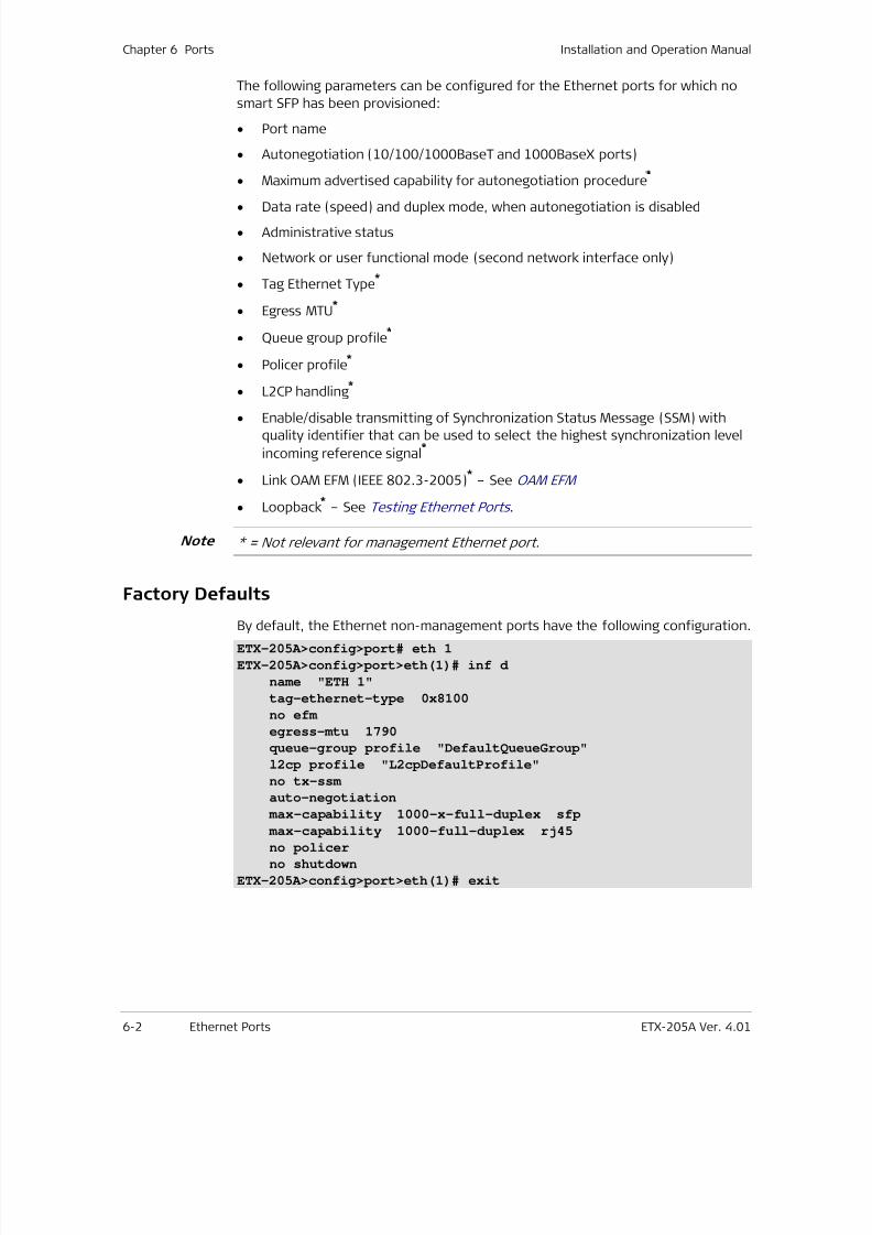
7/25/2019 Manual ETX-205A
http://slidepdf.com/reader/full/manual-etx-205a 138/409
Chapter 6 Ports Installation and Operation Manual
6-2 Ethernet Ports ETX-205A Ver. 4.01
The following parameters can be configured for the Ethernet ports for which no
smart SFP has been provisioned:
• Port name
• Autonegotiation (10/100/1000BaseT and 1000BaseX ports)
• Maximum advertised capability for autonegotiation procedure*
• Data rate (speed) and duplex mode, when autonegotiation is disabled
• Administrative status
• Network or user functional mode (second network interface only)
• Tag Ethernet Type*
• Egress MTU*
• Queue group profile*
• Policer profile*
• L2CP handling*
• Enable/disable transmitting of Synchronization Status Message (SSM) with
quality identifier that can be used to select the highest synchronization level
incoming reference signal*
• Link OAM EFM (IEEE 802.3-2005)*
– See OAM EFM
• Loopback * – See Testing Ethernet Ports .
* = Not relevant for management Ethernet port.
Factory Defaults
By default, the Ethernet non-management ports have the following configuration.
ETX-205A>config>port# eth 1
ETX-205A>config>port>eth(1)# inf d
name "ETH 1"
tag-ethernet-type 0x8100
no efm
egress-mtu 1790
queue-group profile "DefaultQueueGroup"
l2cp profile "L2cpDefaultProfile"
no tx-ssm
auto-negotiation
max-capability 1000-x-full-duplex sfp
max-capability 1000-full-duplex rj45
no policer
no shutdown
ETX-205A>config>port>eth(1)# exit
Note
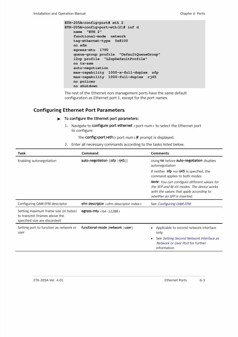
7/25/2019 Manual ETX-205A
http://slidepdf.com/reader/full/manual-etx-205a 139/409
Installation and Operation Manual Chapter 6 Ports
ETX-205A Ver. 4.01 Ethernet Ports 6-3
ETX-205A>config>port# eth 2
ETX-205A>config>port>eth(2)# inf d
name "ETH 2"
functional-mode network
tag-ethernet-type 0x8100
no efm
egress-mtu 1790
queue-group profile "DefaultQueueGroup"l2cp profile "L2cpDefaultProfile"
no tx-ssm
auto-negotiation
max-capability 1000-x-full-duplex sfp
max-capability 1000-full-duplex rj45
no policer
no shutdown
The rest of the Ethernet non-management ports have the same default
configuration as Ethernet port 1, except for the port names.
Configuring Ethernet Port Parameters
To configure the Ethernet port parameters:
1. Navigate to configure port ethernet <port-num> to select the Ethernet port
to configure.
The config>port>eth(<port-num>)# prompt is displayed.
2. Enter all necessary commands according to the tasks listed below.
Task Command Comments
Enabling autonegotiation auto-negotiation [sfp | rj45] Using no before auto-negotiation disables
autonegotiation
If neither sfp nor rj45 is specified, the
command applies to both modes
Note: You can configure different values fo
the SFP and RJ-45 modes. The device works
with the values that apply according to
whether an SFP is inserted.
Configuring OAM EFM descriptorefm descriptor <efm-descriptor-index> See Configuring OAM EFM
Setting maximum frame size (in bytes)
to transmit (frames above the
specified size are discarded)
egress-mtu <64–12288>
Setting port to function as network or
user
functional-mode network | user • Applicable to second network interface
only
• See Setting Second Network Interface a
Network or User Port for further
information
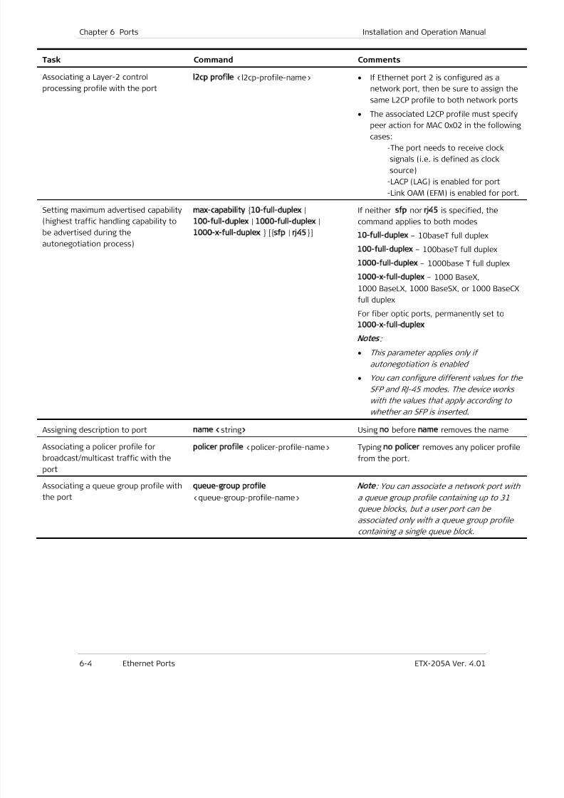
7/25/2019 Manual ETX-205A
http://slidepdf.com/reader/full/manual-etx-205a 140/409
Chapter 6 Ports Installation and Operation Manual
6-4 Ethernet Ports ETX-205A Ver. 4.01
Task Command Comments
Associating a Layer-2 control
processing profile with the port
l2cp profile <l2cp-profile-name> • If Ethernet port 2 is configured as a
network port, then be sure to assign the
same L2CP profile to both network port
• The associated L2CP profile must specify
peer action for MAC 0x02 in the followin
cases:
-The port needs to receive clock
signals (i.e. is defined as clock
source)
-LACP (LAG) is enabled for port
-Link OAM (EFM) is enabled for port
Setting maximum advertised capability
(highest traffic handling capability to
be advertised during the
autonegotiation process)
max-capability 10-full-duplex |
100-full-duplex | 1000-full-duplex |
1000-x-full-duplex [sfp | rj45]
If neither sfp nor rj45 is specified, the
command applies to both modes
10-full-duplex – 10baseT full duplex
100-full-duplex – 100baseT full duplex
1000-full-duplex – 1000base T full duplex1000-x-full-duplex – 1000 BaseX,
1000 BaseLX, 1000 BaseSX, or 1000 BaseC
full duplex
For fiber optic ports, permanently set to
1000-x-full-duplex
Notes:
• This parameter applies only if
autonegotiation is enabled
• You can configure different values for th
SFP and RJ-45 modes. The device works
with the values that apply according to
whether an SFP is inserted.
Assigning description to port name <string> Using no before name removes the name
Associating a policer profile for
broadcast/multicast traffic with the
port
policer profile <policer-profile-name> Typing no policer removes any policer profi
from the port.
Associating a queue group profile with
the port
queue-group profile
<queue-group-profile-name>
Note
: You can associate a network port wit
a queue group profile containing up to 31
queue blocks, but a user port can be
associated only with a queue group profile
containing a single queue block.
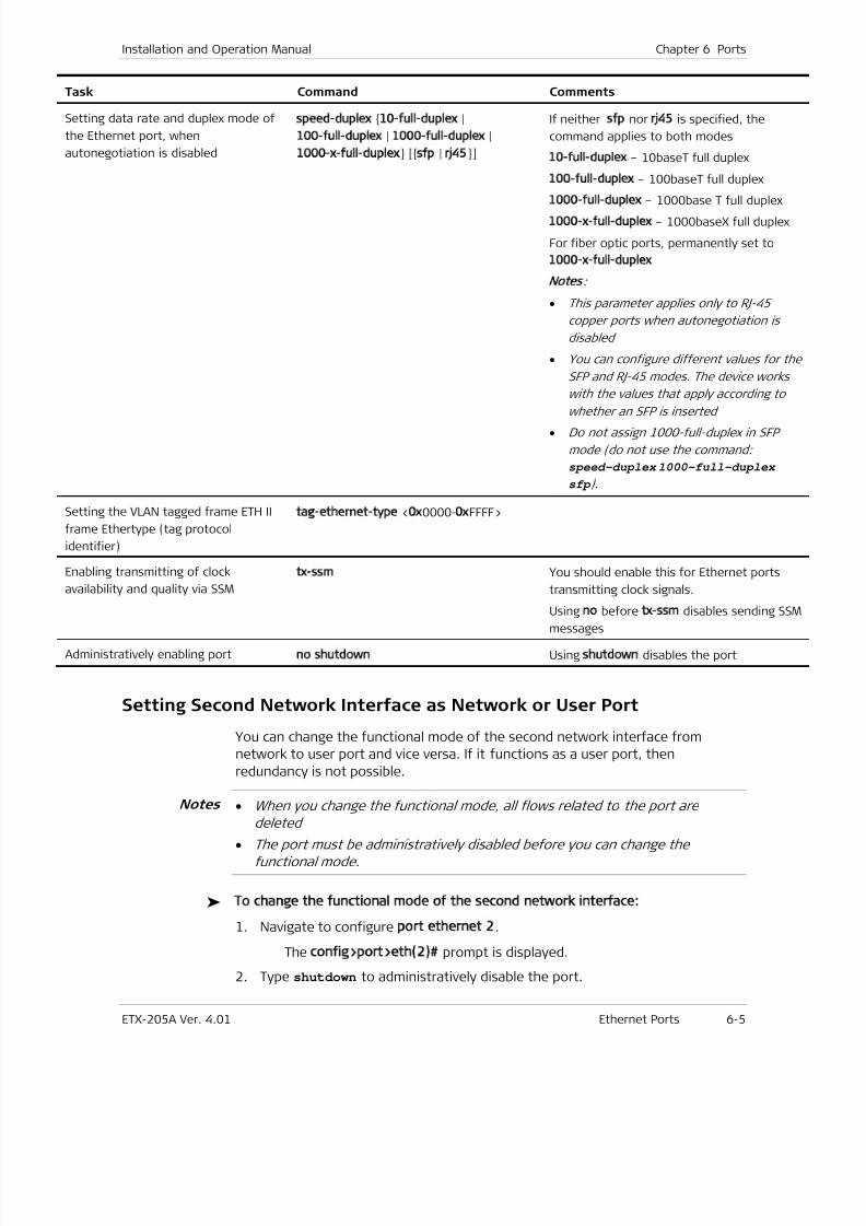
7/25/2019 Manual ETX-205A
http://slidepdf.com/reader/full/manual-etx-205a 141/409
Installation and Operation Manual Chapter 6 Ports
ETX-205A Ver. 4.01 Ethernet Ports 6-5
Task Command Comments
Setting data rate and duplex mode of
the Ethernet port, when
autonegotiation is disabled
speed-duplex 10-full-duplex |
100-full-duplex | 1000-full-duplex |
1000-x-full-duplex [sfp | rj45]
If neither sfp nor rj45 is specified, the
command applies to both modes
10-full-duplex – 10baseT full duplex
100-full-duplex – 100baseT full duplex
1000-full-duplex – 1000base T full duplex1000-x-full-duplex – 1000baseX full duplex
For fiber optic ports, permanently set to
1000-x-full-duplex
Notes
:
• This parameter applies only to RJ-45
copper ports when autonegotiation is
disabled
• You can configure different values for th
SFP and RJ-45 modes. The device works
with the values that apply according to
whether an SFP is inserted
• Do not assign 1000-full-duplex in SFP
mode (do not use the command:
speed-duplex 1000-full-duplex
sfp ).
Setting the VLAN tagged frame ETH II
frame Ethertype (tag protocol
identifier)
tag-ethernet-type <0x0000-0xFFFF>
Enabling transmitting of clock
availability and quality via SSM
tx-ssm You should enable this for Ethernet ports
transmitting clock signals.
Using no before tx-ssm disables sending SSmessages
Administratively enabling portno shutdown Using shutdown disables the port
Setting Second Network Interface as Network or User Port
You can change the functional mode of the second network interface from
network to user port and vice versa. If it functions as a user port, then
redundancy is not possible.
• When you change the functional mode, all flows related to the port are
deleted
• The port must be administratively disabled before you can change the
functional mode.
To change the functional mode of the second network interface:
1. Navigate to configure port ethernet 2.
The config>port>eth(2)# prompt is displayed.
2. Type shutdown to administratively disable the port.
Notes
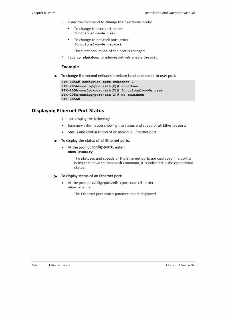
7/25/2019 Manual ETX-205A
http://slidepdf.com/reader/full/manual-etx-205a 142/409
Chapter 6 Ports Installation and Operation Manual
6-6 Ethernet Ports ETX-205A Ver. 4.01
3. Enter the command to change the functional mode:
To change to user port, enter:functional-mode user
To change to network port, enter:functional-mode network
The functional mode of the port is changed.
4. Type no shutdown to administratively enable the port.
Example
To change the second network interface functional mode to user port:
ETX-205A# configure port ethernet 2
ETX-205A>config>port>eth(2)# shutdown
ETX-205A>config>port>eth(2)# functional-mode user
ETX-205A>config>port>eth(2)# no shutdown
ETX-205A#
Displaying Ethernet Port Status
You can display the following:
• Summary information showing the status and speed of all Ethernet ports
• Status and configuration of an individual Ethernet port.
To display the status of all Ethernet ports:
• At the prompt config>port#, enter:show summary
The statuses and speeds of the Ethernet ports are displayed. If a port isbeing tested via the loopback command, it is indicated in the operational
status.
To display status of an Ethernet port:
• At the prompt config>port>eth(<port-num>)#, enter:show status
The Ethernet port status parameters are displayed.
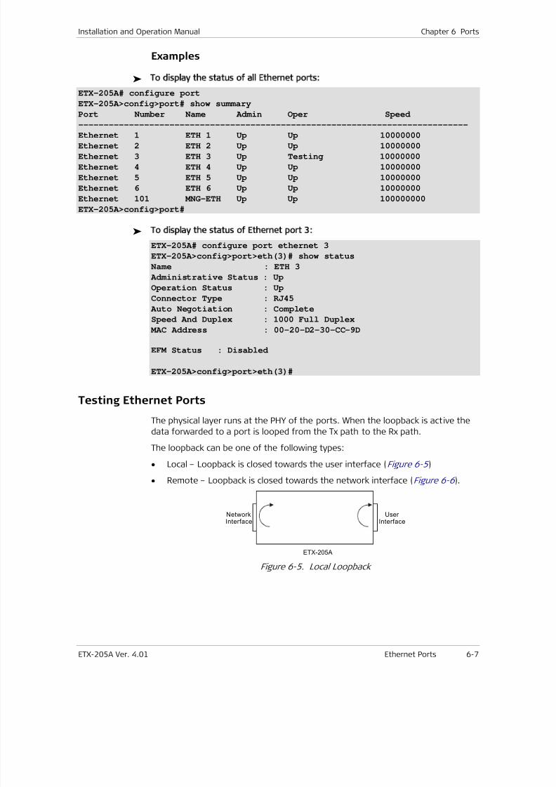
7/25/2019 Manual ETX-205A
http://slidepdf.com/reader/full/manual-etx-205a 143/409
Installation and Operation Manual Chapter 6 Ports
ETX-205A Ver. 4.01 Ethernet Ports 6-7
Examples
To display the status of all Ethernet ports:
ETX-205A# configure port
ETX-205A>config>port# show summary
Port Number Name Admin Oper Speed
-----------------------------------------------------------------------------
Ethernet 1 ETH 1 Up Up 10000000
Ethernet 2 ETH 2 Up Up 10000000
Ethernet 3 ETH 3 Up Testing 10000000
Ethernet 4 ETH 4 Up Up 10000000
Ethernet 5 ETH 5 Up Up 10000000
Ethernet 6 ETH 6 Up Up 10000000
Ethernet 101 MNG-ETH Up Up 100000000
ETX-205A>config>port#
To display the status of Ethernet port 3:
ETX-205A# configure port ethernet 3
ETX-205A>config>port>eth(3)# show status
Name : ETH 3
Administrative Status : Up
Operation Status : Up
Connector Type : RJ45
Auto Negotiation : Complete
Speed And Duplex : 1000 Full Duplex
MAC Address : 00-20-D2-30-CC-9D
EFM Status : Disabled
ETX-205A>config>port>eth(3)#
Testing Ethernet Ports
The physical layer runs at the PHY of the ports. When the loopback is active the
data forwarded to a port is looped from the Tx path to the Rx path.
The loopback can be one of the following types:
• Local – Loopback is closed towards the user interface (Figure 6-5 )
• Remote – Loopback is closed towards the network interface (Figure 6-6 ).
ETX-205A
Network
Interface
User
Interface
Figure 6-5. Local Loopback
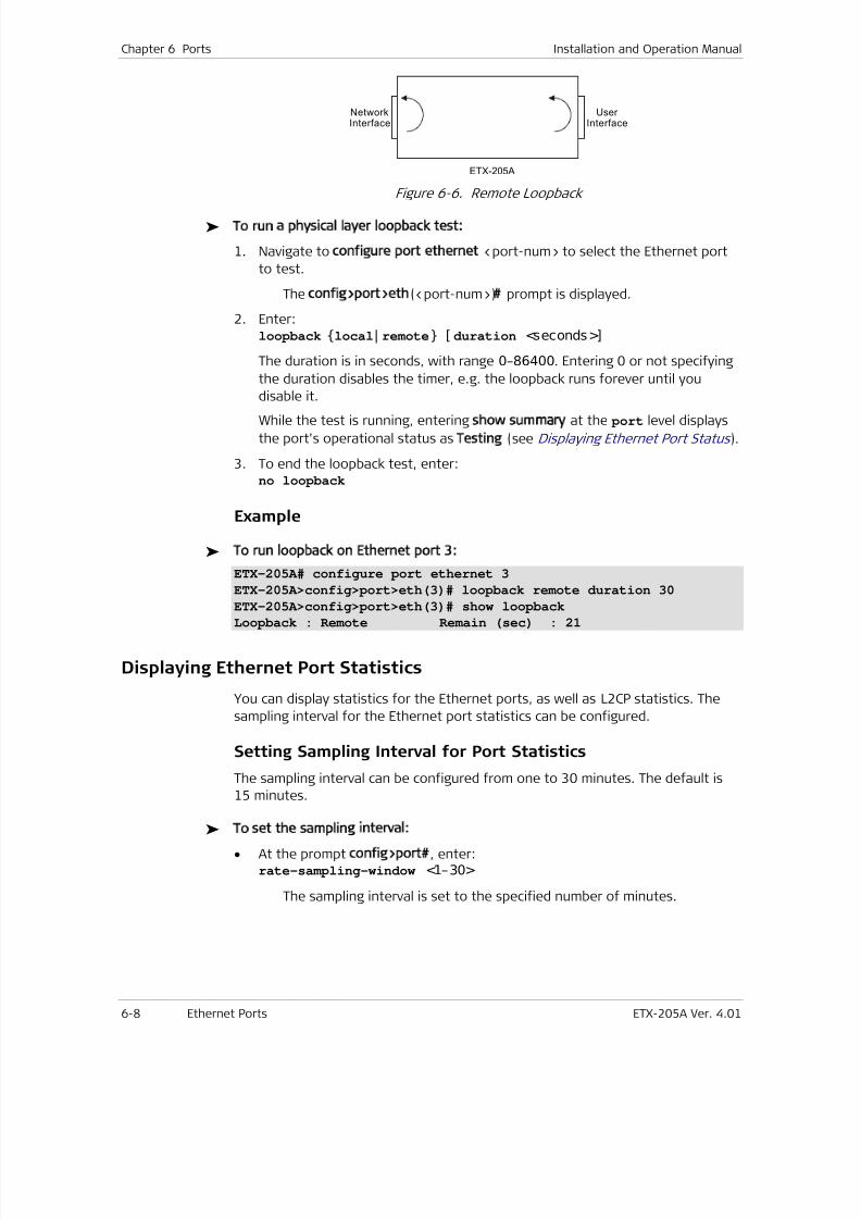
7/25/2019 Manual ETX-205A
http://slidepdf.com/reader/full/manual-etx-205a 144/409
Chapter 6 Ports Installation and Operation Manual
6-8 Ethernet Ports ETX-205A Ver. 4.01
ETX-205A
Network
Interface
User
Interface
Figure 6-6. Remote Loopback
To run a physical layer loopback test:
1. Navigate to configure port ethernet <port-num> to select the Ethernet port
to test.
The config>port>eth(<port-num>)# prompt is displayed.
2. Enter:loopback local| remote [ duration <seconds>]
The duration is in seconds, with range 0–86400. Entering 0 or not specifying
the duration disables the timer, e.g. the loopback runs forever until you
disable it.
While the test is running, entering show summary at the port level displays
the port’s operational status asTesting (see Displaying Ethernet Port Status ).
3. To end the loopback test, enter:no loopback
Example
To run loopback on Ethernet port 3:
ETX-205A# configure port ethernet 3
ETX-205A>config>port>eth(3)# loopback remote duration 30
ETX-205A>config>port>eth(3)# show loopbackLoopback : Remote Remain (sec) : 21
Displaying Ethernet Port Statistics
You can display statistics for the Ethernet ports, as well as L2CP statistics. The
sampling interval for the Ethernet port statistics can be configured.
Setting Sampling Interval for Port Statistics
The sampling interval can be configured from one to 30 minutes. The default is
15 minutes.
To set the sampling interval:
• At the prompt config>port#, enter:rate-sampling-window <1–30>
The sampling interval is set to the specified number of minutes.
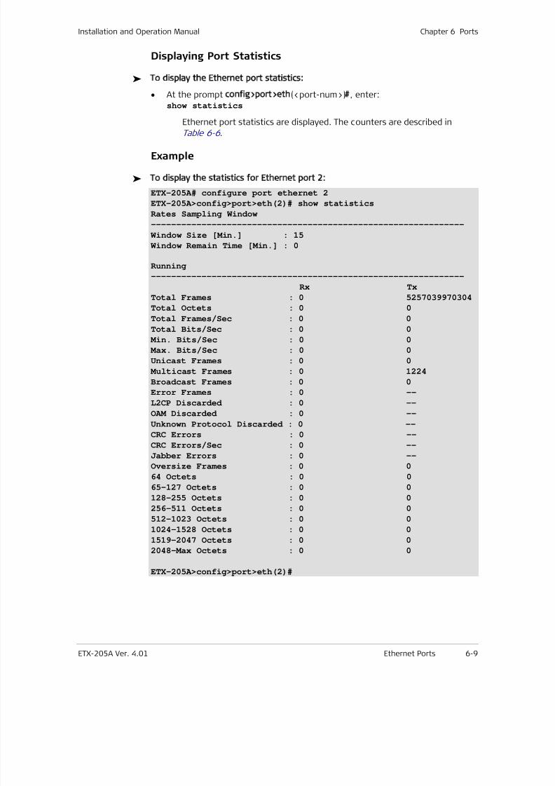
7/25/2019 Manual ETX-205A
http://slidepdf.com/reader/full/manual-etx-205a 145/409
Installation and Operation Manual Chapter 6 Ports
ETX-205A Ver. 4.01 Ethernet Ports 6-9
Displaying Port Statistics
To display the Ethernet port statistics:
• At the prompt config>port>eth(<port-num>)#, enter:show statistics
Ethernet port statistics are displayed. The counters are described in
Table 6-6 .
Example
To display the statistics for Ethernet port 2:
ETX-205A# configure port ethernet 2
ETX-205A>config>port>eth(2)# show statistics
Rates Sampling Window
--------------------------------------------------------------
Window Size [Min.] : 15
Window Remain Time [Min.] : 0
Running
--------------------------------------------------------------
Rx Tx
Total Frames : 0 5257039970304
Total Octets : 0 0
Total Frames/Sec : 0 0
Total Bits/Sec : 0 0
Min. Bits/Sec : 0 0
Max. Bits/Sec : 0 0
Unicast Frames : 0 0
Multicast Frames : 0 1224
Broadcast Frames : 0 0
Error Frames : 0 --L2CP Discarded : 0 --
OAM Discarded : 0 --
Unknown Protocol Discarded : 0 --
CRC Errors : 0 --
CRC Errors/Sec : 0 --
Jabber Errors : 0 --
Oversize Frames : 0 0
64 Octets : 0 0
65-127 Octets : 0 0
128-255 Octets : 0 0
256-511 Octets : 0 0
512-1023 Octets : 0 01024-1528 Octets : 0 0
1519-2047 Octets : 0 0
2048-Max Octets : 0 0
ETX-205A>config>port>eth(2)#
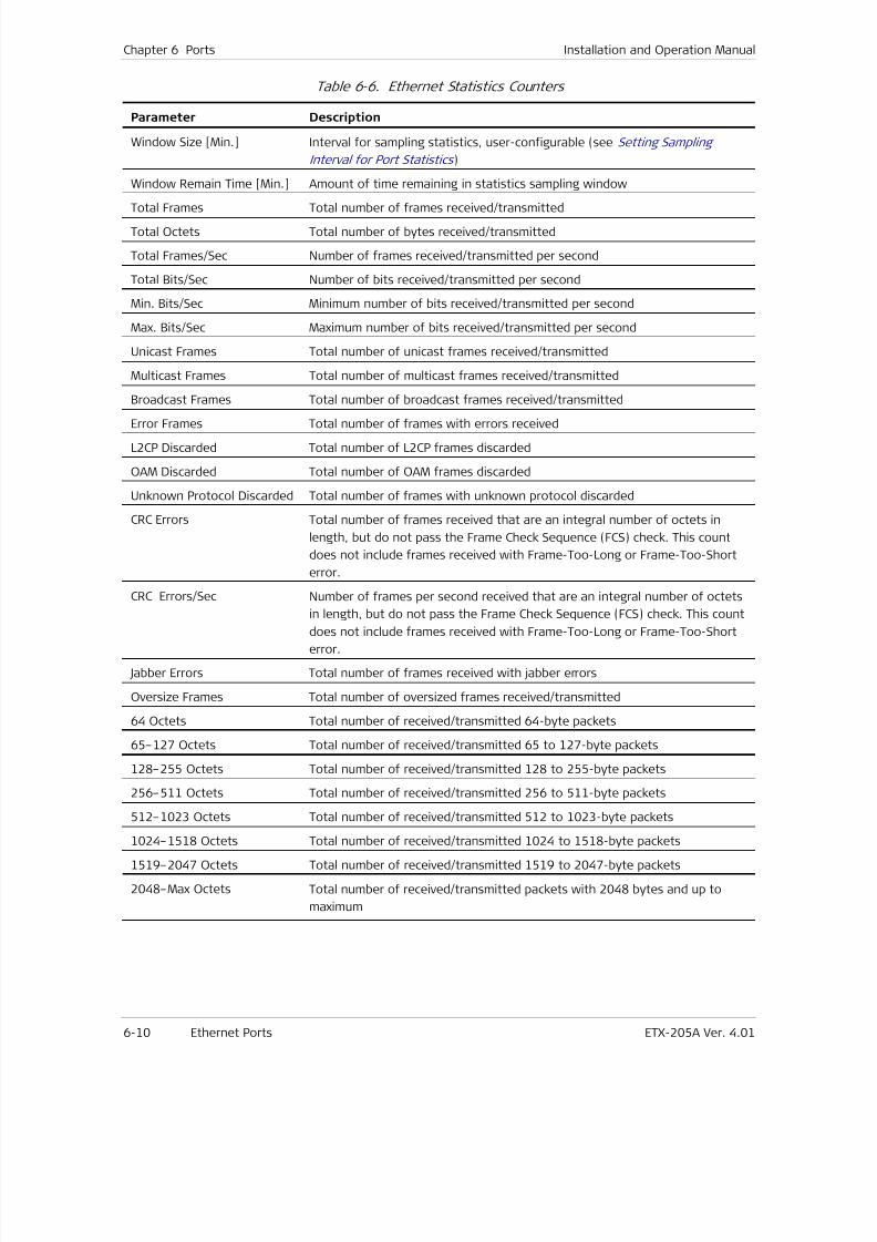
7/25/2019 Manual ETX-205A
http://slidepdf.com/reader/full/manual-etx-205a 146/409
Chapter 6 Ports Installation and Operation Manual
6-10 Ethernet Ports ETX-205A Ver. 4.01
Table 6-6. Ethernet Statistics Counters
Parameter Description
Window Size [Min.] Interval for sampling statistics, user-configurable (see Setting Sampling
Interval for Port Statistics )
Window Remain Time [Min.] Amount of time remaining in statistics sampling window
Total Frames Total number of frames received/transmitted
Total Octets Total number of bytes received/transmitted
Total Frames/Sec Number of frames received/transmitted per second
Total Bits/Sec Number of bits received/transmitted per second
Min. Bits/Sec Minimum number of bits received/transmitted per second
Max. Bits/Sec Maximum number of bits received/transmitted per second
Unicast Frames Total number of unicast frames received/transmitted
Multicast Frames Total number of multicast frames received/transmitted
Broadcast Frames Total number of broadcast frames received/transmitted
Error Frames Total number of frames with errors received
L2CP Discarded Total number of L2CP frames discarded
OAM Discarded Total number of OAM frames discarded
Unknown Protocol Discarded Total number of frames with unknown protocol discarded
CRC Errors Total number of frames received that are an integral number of octets in
length, but do not pass the Frame Check Sequence (FCS) check. This count
does not include frames received with Frame-Too-Long or Frame-Too-Short
error.
CRC Errors/Sec Number of frames per second received that are an integral number of octets
in length, but do not pass the Frame Check Sequence (FCS) check. This countdoes not include frames received with Frame-Too-Long or Frame-Too-Short
error.
Jabber Errors Total number of frames received with jabber errors
Oversize Frames Total number of oversized frames received/transmitted
64 Octets Total number of received/transmitted 64-byte packets
65–127 Octets Total number of received/transmitted 65 to 127-byte packets
128–255 Octets Total number of received/transmitted 128 to 255-byte packets
256–511 Octets Total number of received/transmitted 256 to 511-byte packets
512–1023 Octets Total number of received/transmitted 512 to 1023-byte packets
1024–1518 Octets Total number of received/transmitted 1024 to 1518-byte packets
1519–2047 Octets Total number of received/transmitted 1519 to 2047-byte packets
2048–Max Octets Total number of received/transmitted packets with 2048 bytes and up to
maximum
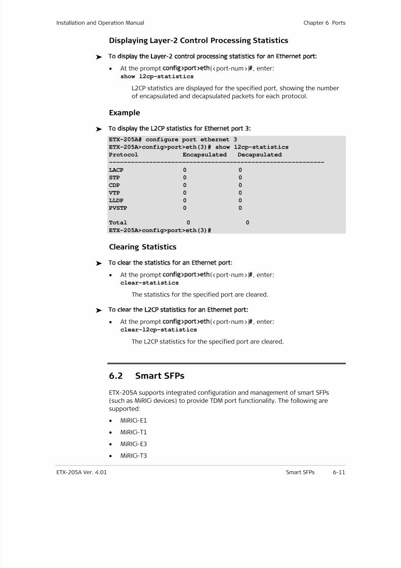
7/25/2019 Manual ETX-205A
http://slidepdf.com/reader/full/manual-etx-205a 147/409
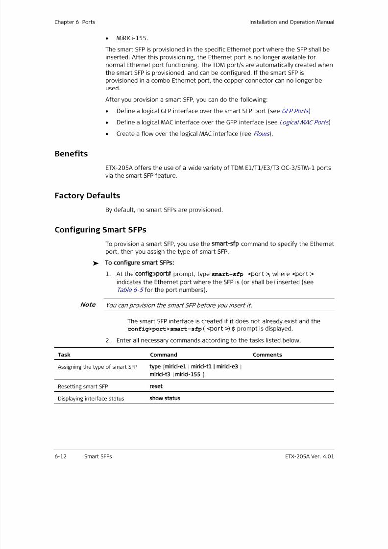
7/25/2019 Manual ETX-205A
http://slidepdf.com/reader/full/manual-etx-205a 148/409
Chapter 6 Ports Installation and Operation Manual
6-12 Smart SFPs ETX-205A Ver. 4.01
• MiRICi-155.
The smart SFP is provisioned in the specific Ethernet port where the SFP shall be
inserted. After this provisioning, the Ethernet port is no longer available for
normal Ethernet port functioning. The TDM port/s are automatically created when
the smart SFP is provisioned, and can be configured. If the smart SFP is
provisioned in a combo Ethernet port, the copper connector can no longer be
used.After you provision a smart SFP, you can do the following:
• Define a logical GFP interface over the smart SFP port (see GFP Ports )
• Define a logical MAC interface over the GFP interface (see Logical MAC Ports )
• Create a flow over the logical MAC interface (ree Flows ).
Benefits
ETX-205A offers the use of a wide variety of TDM E1/T1/E3/T3 OC-3/STM-1 ports
via the smart SFP feature.
Factory Defaults
By default, no smart SFPs are provisioned.
Configuring Smart SFPs
To provision a smart SFP, you use the smart-sfp command to specify the Ethernet
port, then you assign the type of smart SFP.
To configure smart SFPs:
1. At the config>port# prompt, type smart-sfp <por t >, where <por t > indicates the Ethernet port where the SFP is (or shall be) inserted (see
Table 6-5 for the port numbers).
You can provision the smart SFP before you insert it.
The smart SFP interface is created if it does not already exist and theconfig>port>smart-sfp( <port >) $ prompt is displayed.
2. Enter all necessary commands according to the tasks listed below.
Task Command Comments
Assigning the type of smart SFP type mirici-e1 | mirici-t1 | mirici-e3 |
mirici-t3 | mirici-155
Resetting smart SFP reset
Displaying interface status show status
Note
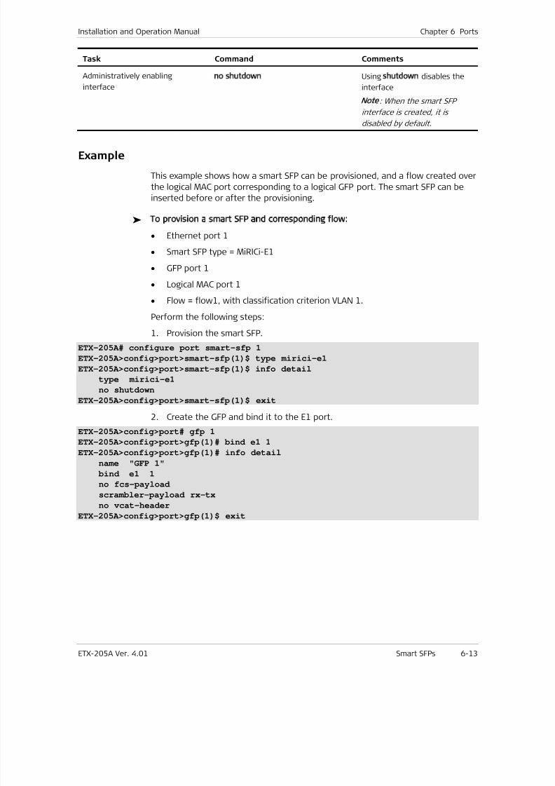
7/25/2019 Manual ETX-205A
http://slidepdf.com/reader/full/manual-etx-205a 149/409
Installation and Operation Manual Chapter 6 Ports
ETX-205A Ver. 4.01 Smart SFPs 6-13
Task Command Comments
Administratively enabling
interface
no shutdown Using shutdown disables the
interface
Note
: When the smart SFP
interface is created, it is
disabled by default.
Example
This example shows how a smart SFP can be provisioned, and a flow created over
the logical MAC port corresponding to a logical GFP port. The smart SFP can be
inserted before or after the provisioning.
To provision a smart SFP and corresponding flow:
• Ethernet port 1
• Smart SFP type = MiRICi-E1
• GFP port 1
• Logical MAC port 1
• Flow = flow1, with classification criterion VLAN 1.
Perform the following steps:
1. Provision the smart SFP.
ETX-205A# configure port smart-sfp 1
ETX-205A>config>port>smart-sfp(1)$ type mirici-e1
ETX-205A>config>port>smart-sfp(1)$ info detail
type mirici-e1
no shutdownETX-205A>config>port>smart-sfp(1)$ exit
2. Create the GFP and bind it to the E1 port.
ETX-205A>config>port# gfp 1
ETX-205A>config>port>gfp(1)# bind e1 1
ETX-205A>config>port>gfp(1)# info detail
name "GFP 1"
bind e1 1
no fcs-payload
scrambler-payload rx-tx
no vcat-header
ETX-205A>config>port>gfp(1)$ exit
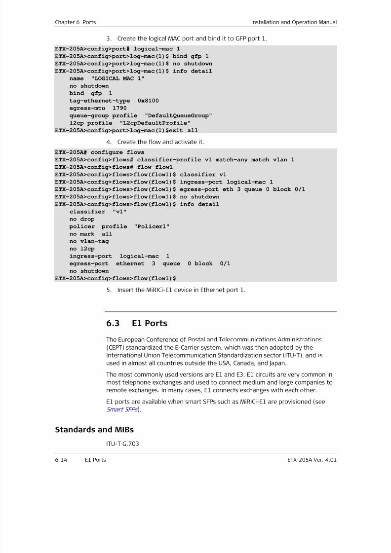
7/25/2019 Manual ETX-205A
http://slidepdf.com/reader/full/manual-etx-205a 150/409
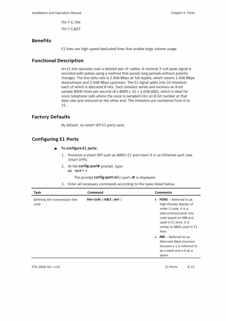
7/25/2019 Manual ETX-205A
http://slidepdf.com/reader/full/manual-etx-205a 151/409
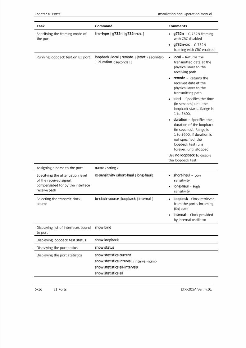
7/25/2019 Manual ETX-205A
http://slidepdf.com/reader/full/manual-etx-205a 152/409
Chapter 6 Ports Installation and Operation Manual
6-16 E1 Ports ETX-205A Ver. 4.01
Task Command Comments
Specifying the framing mode of
the port
line-type g732n | g732n-crc • g732n – G.732N framing
with CRC disabled
• g732n-crc – G.732N
framing with CRC enabled.
Running loopback test on E1 port loopback local | remote [start <seconds>] [duration <seconds>]
• local – Returns thetransmitted data at the
physical layer to the
receiving path
• remote – Returns the
received data at the
physical layer to the
transmitting path
• start – Specifies the time
(in seconds) until the
loopback starts. Range is
1 to 3600.
• duration – Specifies the
duration of the loopback
(in seconds). Range is
1 to 3600. If duration is
not specified, the
loopback test runs
forever, until stopped
Use no loopback to disable
the loopback test.
Assigning a name to the port name <string>
Specifying the attenuation level
of the received signal,
compensated for by the interface
receive path
rx-sensitivity short-haul | long-haul • short-haul – Low
sensitivity
• long-haul – High
sensitivity
Selecting the transmit clock
source
tx-clock-source loopback | internal • loopback –Clock retrieved
from the port's incoming
(Rx) data
• internal – Clock provided
by internal oscillator
Displaying list of interfaces bound
to port
show bind
Displaying loopback test status show loopback
Displaying the port status show status
Displaying the port statistics show statistics current
show statistics interval <interval-num>
show statistics all-intervals
show statistics all
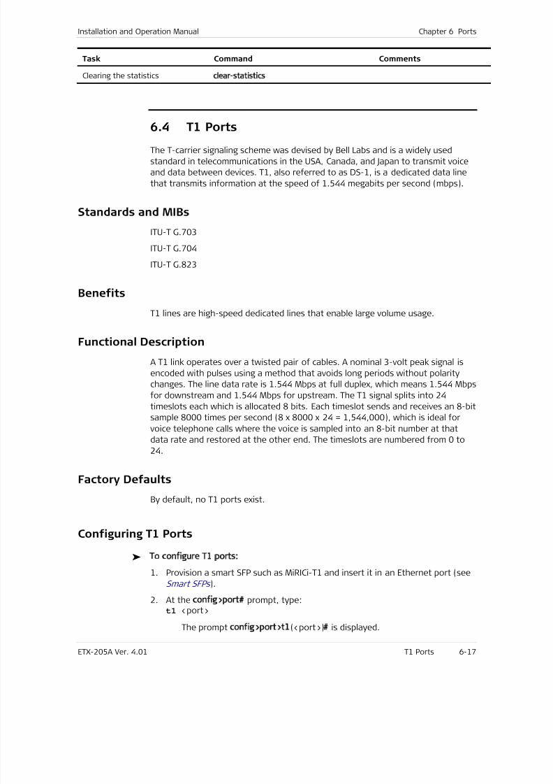
7/25/2019 Manual ETX-205A
http://slidepdf.com/reader/full/manual-etx-205a 153/409
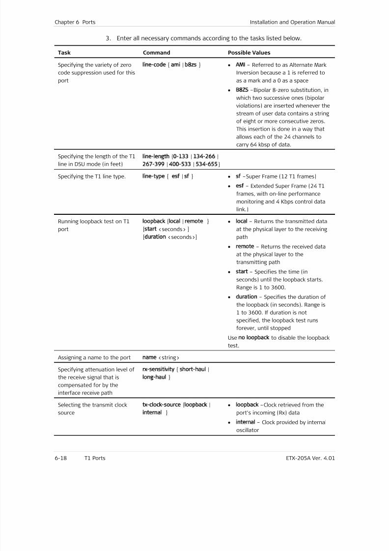
7/25/2019 Manual ETX-205A
http://slidepdf.com/reader/full/manual-etx-205a 154/409
Chapter 6 Ports Installation and Operation Manual
6-18 T1 Ports ETX-205A Ver. 4.01
3. Enter all necessary commands according to the tasks listed below.
Task Command Possible Values
Specifying the variety of zero
code suppression used for this
port
line-code ami | b8zs • AMI – Referred to as Alternate Mark
Inversion because a 1 is referred to
as a mark and a 0 as a space
•
B8ZS –Bipolar 8-zero substitution, inwhich two successive ones (bipolar
violations) are inserted whenever the
stream of user data contains a string
of eight or more consecutive zeros.
This insertion is done in a way that
allows each of the 24 channels to
carry 64 kbsp of data.
Specifying the length of the T1
line in DSU mode (in feet)
line-length 0-133 | 134-266 |
267-399 | 400-533 | 534-655
Specifying the T1 line type. line-type esf | sf • sf –Super Frame (12 T1 frames)
• esf – Extended Super Frame (24 T1
frames, with on-line performance
monitoring and 4 Kbps control data
link.)
Running loopback test on T1
port
loopback local | remote
[start <seconds> ]
[duration <seconds>]
• local – Returns the transmitted data
at the physical layer to the receiving
path
• remote – Returns the received data
at the physical layer to the
transmitting path
• start – Specifies the time (in
seconds) until the loopback starts.
Range is 1 to 3600.
• duration – Specifies the duration of
the loopback (in seconds). Range is
1 to 3600. If duration is not
specified, the loopback test runs
forever, until stopped
Use no loopback to disable the loopback
test.
Assigning a name to the port name <string>
Specifying attenuation level of
the receive signal that is
compensated for by the
interface receive path
rx-sensitivity short-haul |
long-haul
Selecting the transmit clock
source
tx-clock-source loopback |
internal
• loopback –Clock retrieved from the
port's incoming (Rx) data
• internal – Clock provided by internal
oscillator
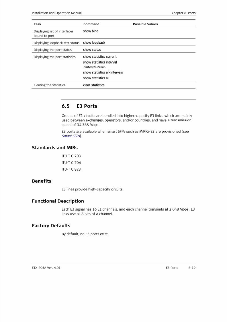
7/25/2019 Manual ETX-205A
http://slidepdf.com/reader/full/manual-etx-205a 155/409
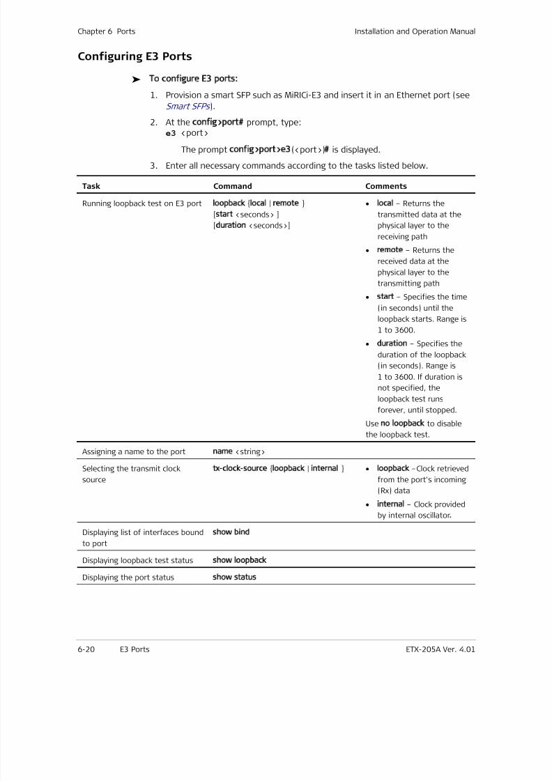
7/25/2019 Manual ETX-205A
http://slidepdf.com/reader/full/manual-etx-205a 156/409
Chapter 6 Ports Installation and Operation Manual
6-20 E3 Ports ETX-205A Ver. 4.01
Configuring E3 Ports
To configure E3 ports:
1. Provision a smart SFP such as MiRICi-E3 and insert it in an Ethernet port (see
Smart SFPs ).
2. At the config>port# prompt, type:e3 <port>
The prompt config>port>e3(<port>)# is displayed.
3. Enter all necessary commands according to the tasks listed below.
Task Command Comments
Running loopback test on E3 port loopback local | remote
[start <seconds> ]
[duration <seconds>]
• local – Returns the
transmitted data at the
physical layer to the
receiving path
• remote – Returns the
received data at thephysical layer to the
transmitting path
• start – Specifies the time
(in seconds) until the
loopback starts. Range is
1 to 3600.
• duration – Specifies the
duration of the loopback
(in seconds). Range is
1 to 3600. If duration is
not specified, theloopback test runs
forever, until stopped.
Use no loopback to disable
the loopback test.
Assigning a name to the port name <string>
Selecting the transmit clock
source
tx-clock-source loopback | internal • loopback –Clock retrieved
from the port's incoming
(Rx) data
• internal – Clock provided
by internal oscillator. Displaying list of interfaces bound
to port
show bind
Displaying loopback test status show loopback
Displaying the port status show status
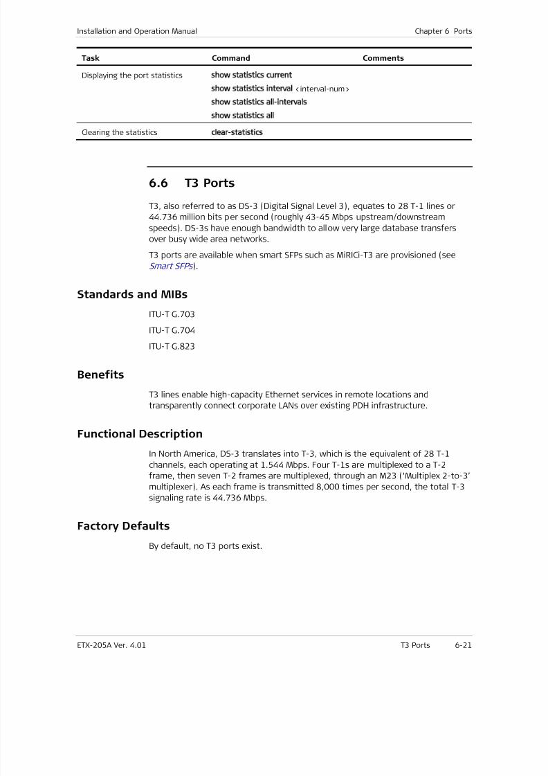
7/25/2019 Manual ETX-205A
http://slidepdf.com/reader/full/manual-etx-205a 157/409
Installation and Operation Manual Chapter 6 Ports
ETX-205A Ver. 4.01 T3 Ports 6-21
Task Command Comments
Displaying the port statistics show statistics current
show statistics interval <interval-num>
show statistics all-intervals
show statistics all
Clearing the statisticsclear-statistics
6.6 T3 Ports
T3, also referred to as DS-3 (Digital Signal Level 3), equates to 28 T-1 lines or
44.736 million bits per second (roughly 43-45 Mbps upstream/downstream
speeds). DS-3s have enough bandwidth to allow very large database transfers
over busy wide area networks.
T3 ports are available when smart SFPs such as MiRICi-T3 are provisioned (seeSmart SFPs ).
Standards and MIBs
ITU-T G.703
ITU-T G.704
ITU-T G.823
Benefits
T3 lines enable high-capacity Ethernet services in remote locations and
transparently connect corporate LANs over existing PDH infrastructure.
Functional Description
In North America, DS-3 translates into T-3, which is the equivalent of 28 T-1
channels, each operating at 1.544 Mbps. Four T-1s are multiplexed to a T-2
frame, then seven T-2 frames are multiplexed, through an M23 (‘Multiplex 2-to-3’
multiplexer). As each frame is transmitted 8,000 times per second, the total T-3
signaling rate is 44.736 Mbps.
Factory Defaults
By default, no T3 ports exist.
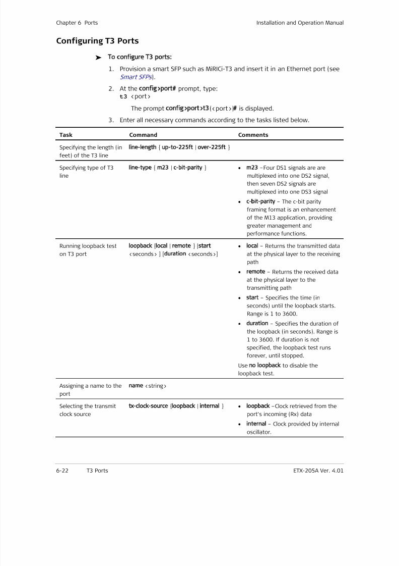
7/25/2019 Manual ETX-205A
http://slidepdf.com/reader/full/manual-etx-205a 158/409
Chapter 6 Ports Installation and Operation Manual
6-22 T3 Ports ETX-205A Ver. 4.01
Configuring T3 Ports
To configure T3 ports:
1. Provision a smart SFP such as MiRICi-T3 and insert it in an Ethernet port (see
Smart SFPs ).
2. At the config>port# prompt, type:t3 <port>
The prompt config>port>t3(<port>)# is displayed.
3. Enter all necessary commands according to the tasks listed below.
Task Command Comments
Specifying the length (in
feet) of the T3 line
line-length up-to-225ft | over-225ft
Specifying type of T3
line
line-type m23 | c-bit-parity • m23 –Four DS1 signals are are
multiplexed into one DS2 signal,
then seven DS2 signals are
multiplexed into one DS3 signal
• c-bit-parity – The c-bit parity
framing format is an enhancement
of the M13 application, providing
greater management and
performance functions.
Running loopback test
on T3 port
loopback local | remote [start
<seconds> ] [duration <seconds>]
• local – Returns the transmitted data
at the physical layer to the receiving
path
• remote – Returns the received data
at the physical layer to thetransmitting path
• start – Specifies the time (in
seconds) until the loopback starts.
Range is 1 to 3600.
• duration – Specifies the duration of
the loopback (in seconds). Range is
1 to 3600. If duration is not
specified, the loopback test runs
forever, until stopped.
Use no loopback to disable the
loopback test.Assigning a name to the
port
name <string>
Selecting the transmit
clock source
tx-clock-source loopback | internal • loopback –Clock retrieved from the
port's incoming (Rx) data
• internal – Clock provided by internal
oscillator.
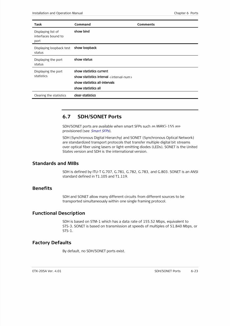
7/25/2019 Manual ETX-205A
http://slidepdf.com/reader/full/manual-etx-205a 159/409
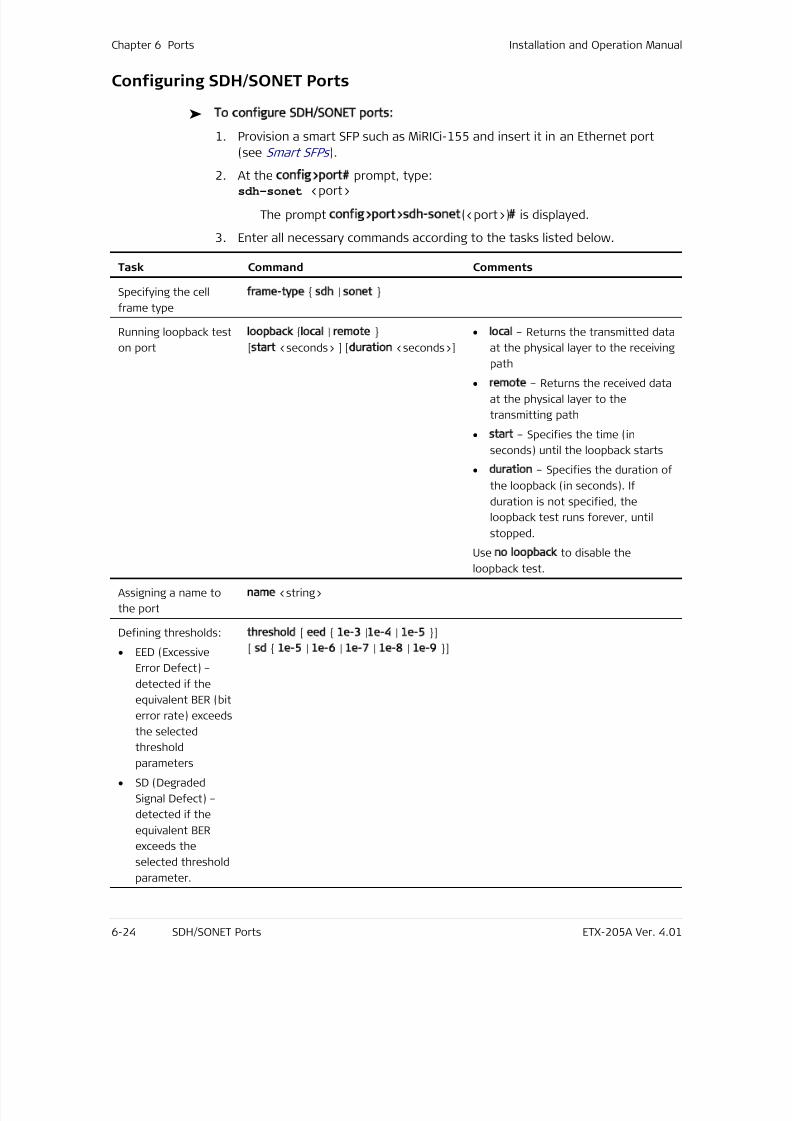
7/25/2019 Manual ETX-205A
http://slidepdf.com/reader/full/manual-etx-205a 160/409
Chapter 6 Ports Installation and Operation Manual
6-24 SDH/SONET Ports ETX-205A Ver. 4.01
Configuring SDH/SONET Ports
To configure SDH/SONET ports:
1. Provision a smart SFP such as MiRICi-155 and insert it in an Ethernet port
(see Smart SFPs ).
2. At the config>port# prompt, type:sdh-sonet <port>
The prompt config>port>sdh-sonet(<port>)# is displayed.
3. Enter all necessary commands according to the tasks listed below.
Task Command Comments
Specifying the cell
frame type
frame-type sdh | sonet
Running loopback test
on port
loopback local | remote
[start <seconds> ] [duration <seconds>]
• local – Returns the transmitted data
at the physical layer to the receiving
path
• remote – Returns the received data
at the physical layer to the
transmitting path
• start – Specifies the time (in
seconds) until the loopback starts
• duration – Specifies the duration of
the loopback (in seconds). If
duration is not specified, the
loopback test runs forever, until
stopped.
Use no loopback to disable the
loopback test.
Assigning a name to
the port
name <string>
Defining thresholds:
• EED (Excessive
Error Defect) –
detected if the
equivalent BER (bit
error rate) exceeds
the selected
thresholdparameters
• SD (Degraded
Signal Defect) –
detected if the
equivalent BER
exceeds the
selected threshold
parameter.
threshold [ eed 1e-3 |1e-4 | 1e-5 ]
[ sd 1e-5 | 1e-6 | 1e-7 | 1e-8 | 1e-9 ]
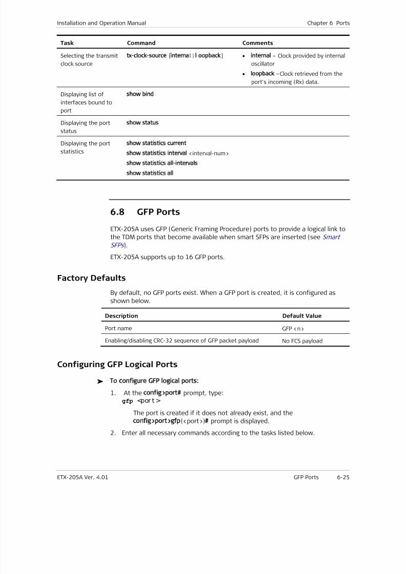
7/25/2019 Manual ETX-205A
http://slidepdf.com/reader/full/manual-etx-205a 161/409
Installation and Operation Manual Chapter 6 Ports
ETX-205A Ver. 4.01 GFP Ports 6-25
Task Command Comments
Selecting the transmit
clock source
tx-clock-source internal | l oopback • internal – Clock provided by internal
oscillator
• loopback –Clock retrieved from the
port's incoming (Rx) data.
Displaying list ofinterfaces bound to
port
show bind
Displaying the port
status
show status
Displaying the port
statistics
show statistics current
show statistics interval <interval-num>
show statistics all-intervals
show statistics all
6.8 GFP Ports
ETX-205A uses GFP (Generic Framing Procedure) ports to provide a logical link to
the TDM ports that become available when smart SFPs are inserted (see Smart
SFPs ).
ETX-205A supports up to 16 GFP ports.
Factory Defaults
By default, no GFP ports exist. When a GFP port is created, it is configured as
shown below.
Description Default Value
Port name GFP <n>
Enabling/disabling CRC-32 sequence of GFP packet payload No FCS payload
Configuring GFP Logical Ports
To configure GFP logical ports:
1. At the config>port# prompt, type:gfp <por t >
The port is created if it does not already exist, and the
config>port>gfp(<port>)# prompt is displayed.
2. Enter all necessary commands according to the tasks listed below.
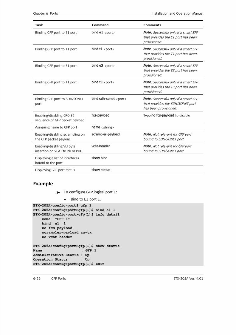
7/25/2019 Manual ETX-205A
http://slidepdf.com/reader/full/manual-etx-205a 162/409
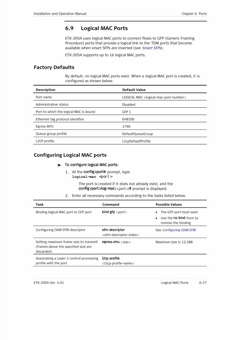
7/25/2019 Manual ETX-205A
http://slidepdf.com/reader/full/manual-etx-205a 163/409
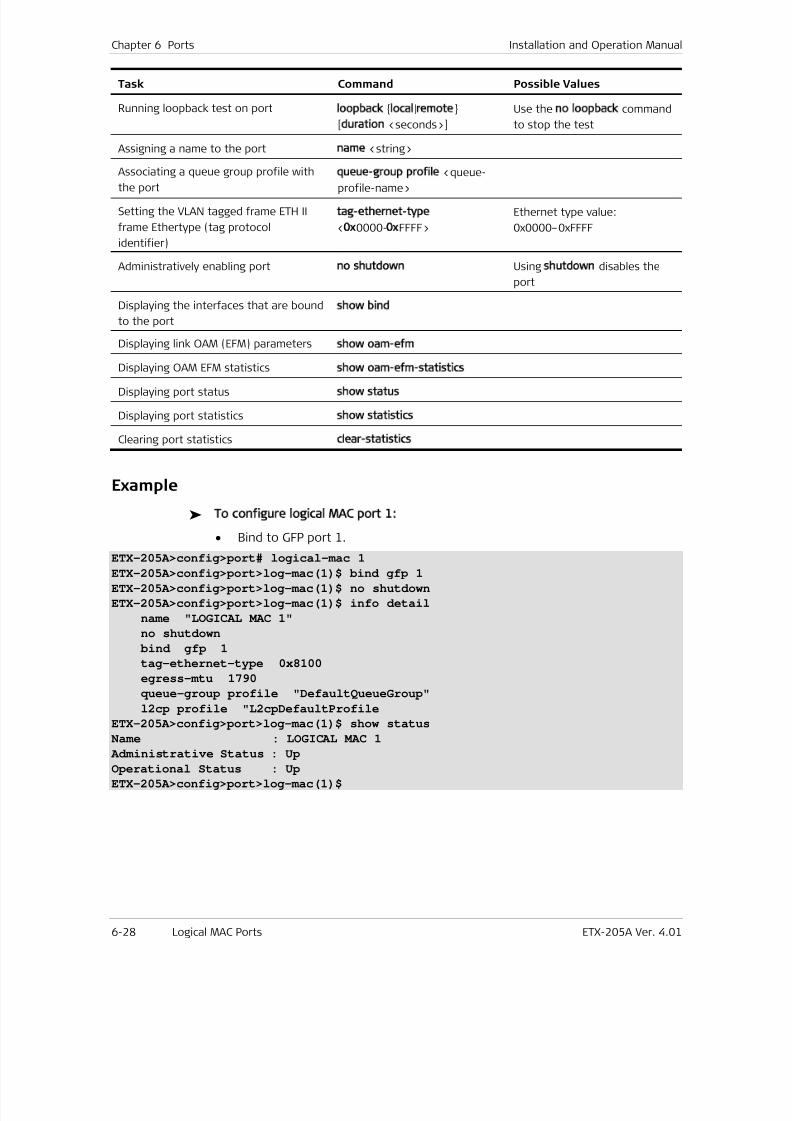
7/25/2019 Manual ETX-205A
http://slidepdf.com/reader/full/manual-etx-205a 164/409
Chapter 6 Ports Installation and Operation Manual
6-28 Logical MAC Ports ETX-205A Ver. 4.01
Task Command Possible Values
Running loopback test on portloopback local|remote
[duration <seconds>]
Use the no loopback command
to stop the test
Assigning a name to the port name <string>
Associating a queue group profile with
the port
queue-group profile <queue-
profile-name>
Setting the VLAN tagged frame ETH II
frame Ethertype (tag protocol
identifier)
tag-ethernet-type
<0x0000-0xFFFF>
Ethernet type value:
0x0000–0xFFFF
Administratively enabling port no shutdown Using shutdown disables the
port
Displaying the interfaces that are bound
to the port
show bind
Displaying link OAM (EFM) parametersshow oam-efm
Displaying OAM EFM statistics show oam-efm-statistics
Displaying port status show status
Displaying port statistics show statistics
Clearing port statistics clear-statistics
Example
To configure logical MAC port 1:
• Bind to GFP port 1.
ETX-205A>config>port# logical-mac 1ETX-205A>config>port>log-mac(1)$ bind gfp 1
ETX-205A>config>port>log-mac(1)$ no shutdown
ETX-205A>config>port>log-mac(1)$ info detail
name "LOGICAL MAC 1"
no shutdown
bind gfp 1
tag-ethernet-type 0x8100
egress-mtu 1790
queue-group profile "DefaultQueueGroup"
l2cp profile "L2cpDefaultProfile
ETX-205A>config>port>log-mac(1)$ show status
Name : LOGICAL MAC 1
Administrative Status : Up
Operational Status : Up
ETX-205A>config>port>log-mac(1)$
7/25/2019 Manual ETX-205A
http://slidepdf.com/reader/full/manual-etx-205a 165/409
Installation and Operation Manual Chapter 6 Ports
ETX-205A Ver. 4.01 Service Virtual Interfaces 6-29
6.10 Service Virtual Interfaces
Service virtual interfaces (SVIs) are logical ports used to link router interfaces with
Ethernet ports (via Layer-2 flows).
ETX-205A supports up to eight SVIs.
Configuring Service Virtual Interfaces
You can enable and operate service virtual interfaces as explained below.
To configure the SVI parameters:
1. Navigate to configure port svi <port-num> to select the SVI to configure.
The config>port>svi(<port-num>)# prompt is displayed.
2. Enter all necessary commands according to the tasks listed below.
Task Command Comments
Setting the port namename <string>
Administratively enabling SVIno shutdown Using shutdown disables the SVI
Note

7/25/2019 Manual ETX-205A
http://slidepdf.com/reader/full/manual-etx-205a 166/409
7/25/2019 Manual ETX-205A
http://slidepdf.com/reader/full/manual-etx-205a 167/409
ETX-205A Ver. 4.01 Ethernet Linear Protection 7-1
Chapter 7
Resiliency
This chapter describes features related to resiliency:
• Ethernet Linear Protection
• Fault Propagation
• Network Interface Redundancy .
7.1 Ethernet Linear Protection
ETX-205A provides protection switching in the following modes for network portsper ITU-T G.8031:
• 1:1
• Unidirectional
• Using APS messages.
The triggers are:
• Port Signal loss
• CCM LOC
•
ETH-AIS.The protection time is as follows:
• One EVC pair — 50ms protection
• Four EVC pairs — 200ms protection.
Standards
ITU-T G.8031
Benefits
The Ethernet linear protection provides a way to protect the flows belonging to
an EVC.
Functional Description
The protection is based on an EVC Termination Point (ETP). An ETP has one
subscriber port and one or more transport ports. Multiple transport ports are
used for protection only. There are two kinds of flows connected to the ETP
ports, subscriber flows and transport flows.
7/25/2019 Manual ETX-205A
http://slidepdf.com/reader/full/manual-etx-205a 168/409
Chapter 7 Resiliency Installation and Operation Manual
7-2 Ethernet Linear Protection ETX-205A Ver. 4.01
• Subscriber flows run between UNIs and ETP subscriber port. You can define
classification and policing on subscriber flows. You cannot define actions such
as push and pop on subscriber flows, however you can define marking.
• Transport flows run between ETP transport ports and NNIs. You can define
actions such as push, pop, and marking on transport flows.
Flows entering the ETP assign an internal CoS value to every frame using mapping
profiles (priority-to-CoS) or by setting fixed CoS values.
Flows exiting the ETP perform queuing based on the internal CoS value using
mapping profiles (CoS-to-queue).
ETP Flow Attributes
The following table shows which attributes you can configure for ETP flows.
Table 7-7. ETP Flow Attributes
Attribute Subscriber
(UNI to ETP)
Subscriber
(ETP to UNI)
Transport
(NNI to ETP)
Transport
(ETP to NNI)
Ingress port Required Required Required Required
Egress port Required Required Required Required
Classifier profile Required, with any type
of criteria
Required, with
criteria:
Unclassified
VLAN
Required, with
criteria:
SP VLAN
Required, with
criteria:
Unclassified
Policer profile Optional Optional Not allowed Not allowed
Queue / block Not allowed Required, with
queue mapping
profile classifiedby CoS
Not allowed Required, with
queue mapping
profile classifiedby CoS
CoS Required, with CoS
mapping profile
Not allowed Required, with
CoS mapping
profile
Not allowed
VLAN tag (push) Optional Not allowed Not allowed For at least one
of the actions,
marking profile
classified by CoS
Mark Required, with marking
profile classified by CoS
Required, with
CoS mapping
profile
For at least
one of the
actions, CoS
mapping profileVLAN tag (pop) Not allowed Optional Not allowed
Drop Optional Optional Optional Optional
EVC Protection Switching
EVC protection (1:1) is based on the ETP model. One of the transport ports is the
working transport entity and the other port serves as the protection transport
entity.
7/25/2019 Manual ETX-205A
http://slidepdf.com/reader/full/manual-etx-205a 169/409
Installation and Operation Manual Chapter 7 Resiliency
ETX-205A Ver. 4.01 Ethernet Linear Protection 7-3
Monitoring both working and protection transport entity is done via MEPs
exchanging CCMs. In addition the protection transport optionally runs APS
protocol.
Master and Slave ETPs
You can define one master ETP and several slave ETPs. The master ETP must have
all the configuration of the protection, same as single ETP. The slave ETPs pointto the master ETP via master command and bind each port ID to
working/protection.
The master ETP index MUST be lower than the index of the slave ETPs. You must
create the master ETP before creating the slave ETPs.
EVC and OAM
On each transport entity you must define a MEP in order to monitor the
connection using CCM. The MEPs must be activated so that the protection
switching mechanism can monitor both working and protection transport entities.
The monitoring is accomplished by exchanging CCMs as defined in ITU-T Rec.
Y.1731.
In addition the MEP can be defined to perform other Y.1731 services such as
measuring delay and loss on the specific EVC.
EVC Fault Propagation
You can define fault propagation based on EVC failure detection (ETP operation
status) to shut down the UNIs that connect to it. The fault trigger can be on of
the following:
• In case of protection: the signal failure trigger MEP for ETP transport ports
• In other cases: the NNI operation status.
EVC Loopback
A loopback can be activated on any of the transport ports towards the network
and on the subscriber port towards the user or network.
In most cases you would activate a loop on the subscriber port towards the
network, thus you can loop the EVC traffic without affecting protection.
If you wish to run a loop on a specific EVC path when you activate the loop on
the transport ports, you have two options:
• Loopback on a transport port affects OAM, as any traffic EVC path
redundancy is triggered if present.
• Loopback only data without affecting redundancy.
Factory Defaults
By default, no ETPs are configured.
When you create an ETP port, by default it is configured as follows:
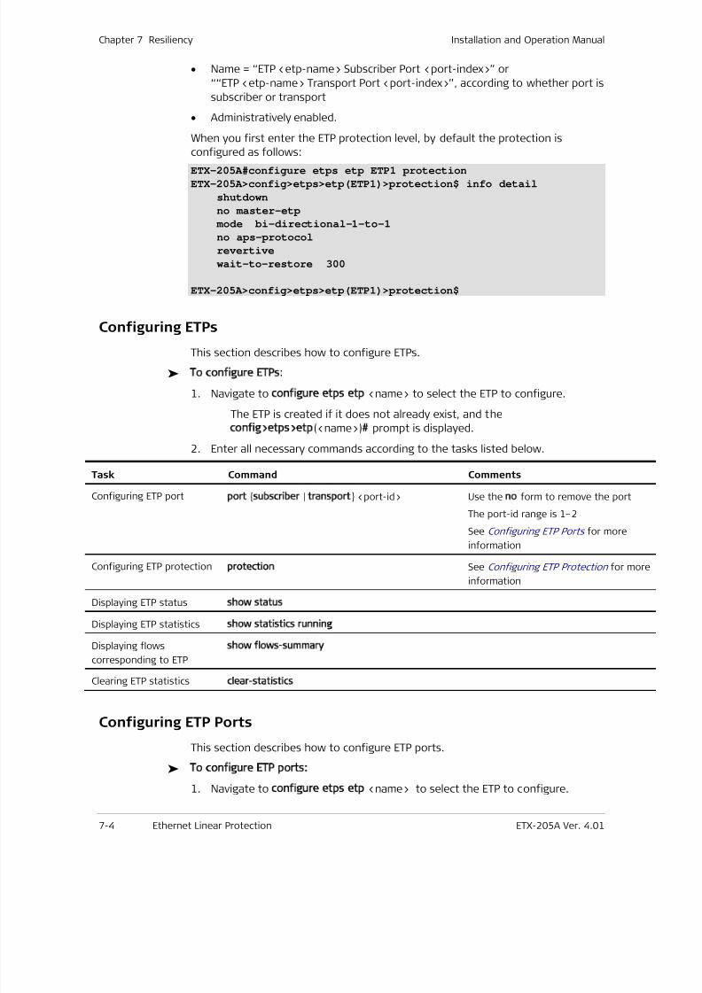
7/25/2019 Manual ETX-205A
http://slidepdf.com/reader/full/manual-etx-205a 170/409
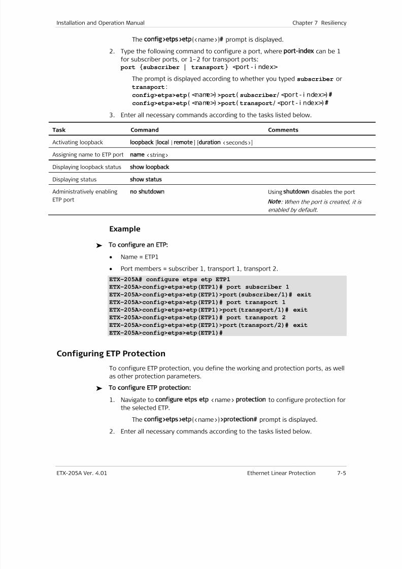
7/25/2019 Manual ETX-205A
http://slidepdf.com/reader/full/manual-etx-205a 171/409
Installation and Operation Manual Chapter 7 Resiliency
ETX-205A Ver. 4.01 Ethernet Linear Protection 7-5
The config>etps>etp(<name>)# prompt is displayed.
2. Type the following command to configure a port, where port-index can be 1
for subscriber ports, or 1–2 for transport ports: port subscriber | transport <port - i ndex>
The prompt is displayed according to whether you typed subscriber or
transport:
config>etps>etp( <name>) >port( subscriber/ <port - i ndex>)#
config>etps>etp( <name>) >port( transport/ <port - i ndex>) #
3. Enter all necessary commands according to the tasks listed below.
Task Command Comments
Activating loopbackloopback [local | remote] [duration <seconds>]
Assigning name to ETP portname <string>
Displaying loopback statusshow loopback
Displaying statusshow status
Administratively enabling
ETP port
no shutdown Using shutdown disables the port
Note: When the port is created, it is
enabled by default.
Example
To configure an ETP:
• Name = ETP1
• Port members = subscriber 1, transport 1, transport 2.
ETX-205A# configure etps etp ETP1
ETX-205A>config>etps>etp(ETP1)# port subscriber 1
ETX-205A>config>etps>etp(ETP1)>port(subscriber/1)# exit
ETX-205A>config>etps>etp(ETP1)# port transport 1
ETX-205A>config>etps>etp(ETP1)>port(transport/1)# exit
ETX-205A>config>etps>etp(ETP1)# port transport 2
ETX-205A>config>etps>etp(ETP1)>port(transport/2)# exit
ETX-205A>config>etps>etp(ETP1)#
Configuring ETP Protection
To configure ETP protection, you define the working and protection ports, as well
as other protection parameters. To configure ETP protection:
1. Navigate to configure etps etp <name> protection to configure protection for
the selected ETP.
The config>etps>etp(<name>)>protection# prompt is displayed.
2. Enter all necessary commands according to the tasks listed below.
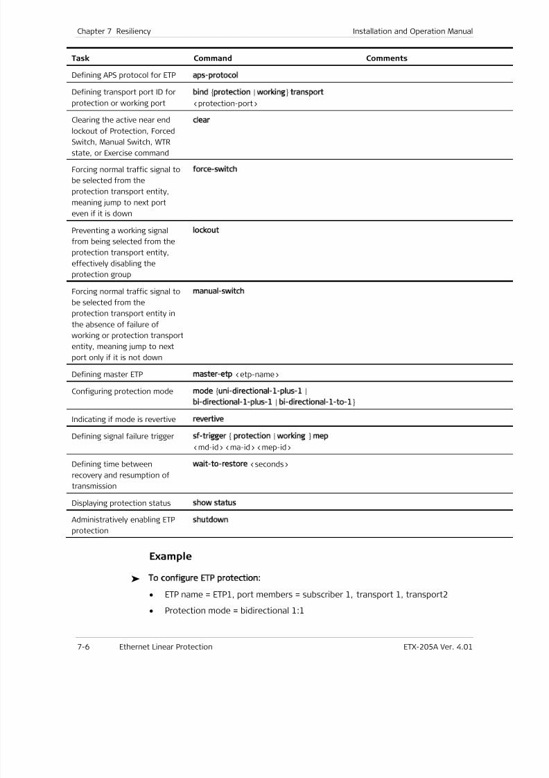
7/25/2019 Manual ETX-205A
http://slidepdf.com/reader/full/manual-etx-205a 172/409
Chapter 7 Resiliency Installation and Operation Manual
7-6 Ethernet Linear Protection ETX-205A Ver. 4.01
Task Command Comments
Defining APS protocol for ETPaps-protocol
Defining transport port ID for
protection or working port
bind protection | working transport
<protection-port>
Clearing the active near end
lockout of Protection, ForcedSwitch, Manual Switch, WTR
state, or Exercise command
clear
Forcing normal traffic signal to
be selected from the
protection transport entity,
meaning jump to next port
even if it is down
force-switch
Preventing a working signal
from being selected from the
protection transport entity,
effectively disabling the
protection group
lockout
Forcing normal traffic signal to
be selected from the
protection transport entity in
the absence of failure of
working or protection transport
entity, meaning jump to next
port only if it is not down
manual-switch
Defining master ETP master-etp <etp-name>
Configuring protection mode mode uni-directional-1-plus-1 |
bi-directional-1-plus-1 | bi-directional-1-to-1
Indicating if mode is revertive revertive
Defining signal failure trigger sf-trigger protection | working mep
<md-id> <ma-id> <mep-id>
Defining time between
recovery and resumption of
transmission
wait-to-restore <seconds>
Displaying protection status show status
Administratively enabling ETP
protection
shutdown
Example
To configure ETP protection:
• ETP name = ETP1, port members = subscriber 1, transport 1, transport2
• Protection mode = bidirectional 1:1
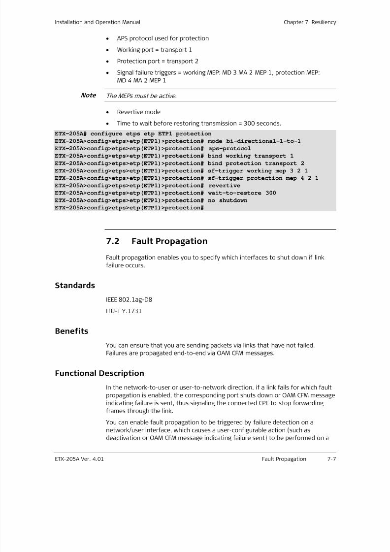
7/25/2019 Manual ETX-205A
http://slidepdf.com/reader/full/manual-etx-205a 173/409
Installation and Operation Manual Chapter 7 Resiliency
ETX-205A Ver. 4.01 Fault Propagation 7-7
• APS protocol used for protection
• Working port = transport 1
• Protection port = transport 2
• Signal failure triggers = working MEP: MD 3 MA 2 MEP 1, protection MEP:
MD 4 MA 2 MEP 1
The MEPs must be active.
• Revertive mode
• Time to wait before restoring transmission = 300 seconds.
ETX-205A# configure etps etp ETP1 protection
ETX-205A>config>etps>etp(ETP1)>protection# mode bi-directional-1-to-1
ETX-205A>config>etps>etp(ETP1)>protection# aps-protocol
ETX-205A>config>etps>etp(ETP1)>protection# bind working transport 1
ETX-205A>config>etps>etp(ETP1)>protection# bind protection transport 2
ETX-205A>config>etps>etp(ETP1)>protection# sf-trigger working mep 3 2 1
ETX-205A>config>etps>etp(ETP1)>protection# sf-trigger protection mep 4 2 1
ETX-205A>config>etps>etp(ETP1)>protection# revertive
ETX-205A>config>etps>etp(ETP1)>protection# wait-to-restore 300
ETX-205A>config>etps>etp(ETP1)>protection# no shutdown
ETX-205A>config>etps>etp(ETP1)>protection#
7.2 Fault Propagation
Fault propagation enables you to specify which interfaces to shut down if link
failure occurs.
Standards
IEEE 802.1ag-D8
ITU-T Y.1731
Benefits
You can ensure that you are sending packets via links that have not failed.
Failures are propagated end-to-end via OAM CFM messages.
Functional Description
In the network-to-user or user-to-network direction, if a link fails for which fault
propagation is enabled, the corresponding port shuts down or OAM CFM message
indicating failure is sent, thus signaling the connected CPE to stop forwarding
frames through the link.
You can enable fault propagation to be triggered by failure detection on a
network/user interface, which causes a user-configurable action (such as
deactivation or OAM CFM message indicating failure sent) to be performed on a
Note
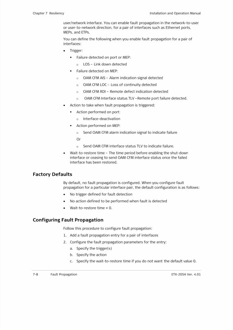
7/25/2019 Manual ETX-205A
http://slidepdf.com/reader/full/manual-etx-205a 174/409
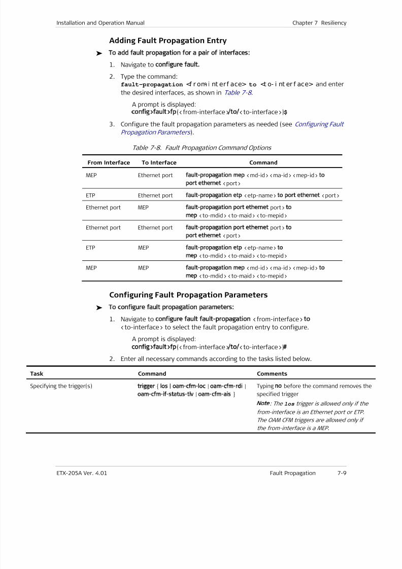
7/25/2019 Manual ETX-205A
http://slidepdf.com/reader/full/manual-etx-205a 175/409
Installation and Operation Manual Chapter 7 Resiliency
ETX-205A Ver. 4.01 Fault Propagation 7-9
Adding Fault Propagation Entry
To add fault propagation for a pair of interfaces:
1. Navigate to configure fault.
2. Type the command:fault-propagation <f r om- i nt erf ace> to <t o- i nt er f ace> and enter
the desired interfaces, as shown in Table 7-8 . A prompt is displayed:config>fault>fp(<from-interface>/to/<to-interface>)$
3. Configure the fault propagation parameters as needed (see Configuring Fault
Propagation Parameters ).
Table 7-8. Fault Propagation Command Options
From Interface To Interface Command
MEP Ethernet port fault-propagation mep
<md-id>
<ma-id>
<mep-id> to
port ethernet <port>
ETP Ethernet port fault-propagation etp <etp-name> to port ethernet <port>
Ethernet port MEP fault-propagation port
ethernet
port> to
mep <to-mdid> <to-maid> <to-mepid>
Ethernet port Ethernet port fault-propagation port ethernet port> to
port
ethernet
<port>
ETP MEP fault-propagation etp <etp-name> to
mep <to-mdid> <to-maid> <to-mepid>
MEP MEP fault-propagation mep
<md-id>
<ma-id>
<mep-id> to
mep <to-mdid> <to-maid> <to-mepid>
Configuring Fault Propagation Parameters
To configure fault propagation parameters:
1. Navigate to configure fault fault-propagation <from-interface> to
<to-interface> to select the fault propagation entry to configure.
A prompt is displayed:
config>fault>fp(<from-interface>/to/<to-interface>)#
2. Enter all necessary commands according to the tasks listed below.
Task Command Comments
Specifying the trigger(s)trigger los | oam-cfm-loc | oam-cfm-rdi |
oam-cfm-if-status-tlv | oam-cfm-ais
Typing no before the command removes th
specified trigger
Note: The los trigger is allowed only if the
from-interface is an Ethernet port or ETP.
The OAM CFM triggers are allowed only if
the from-interface is a MEP.
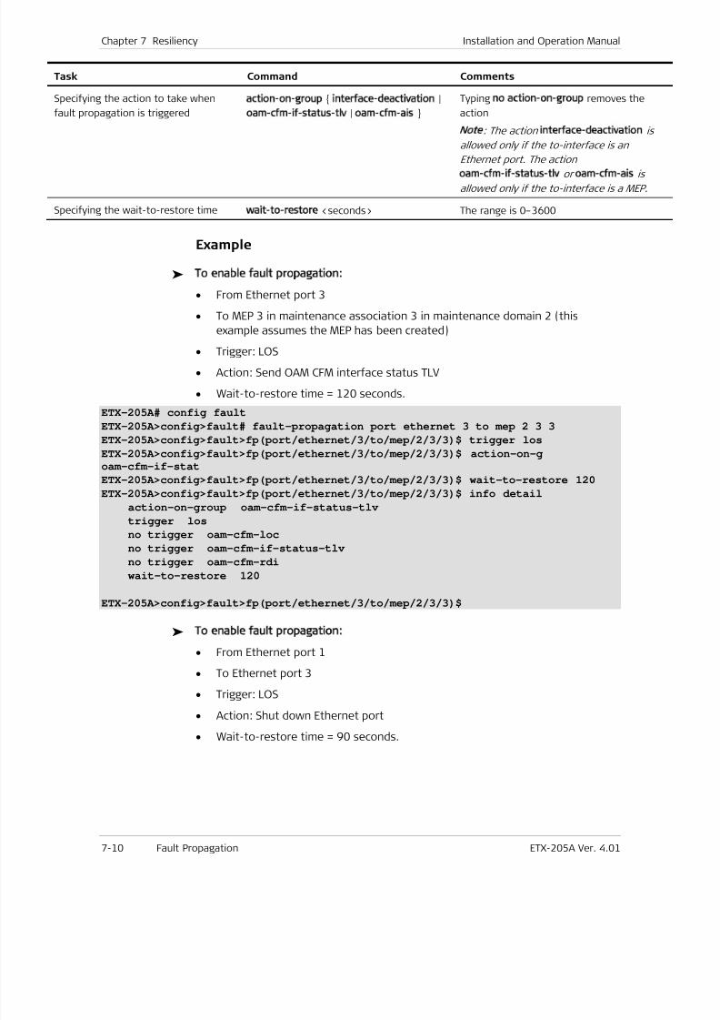
7/25/2019 Manual ETX-205A
http://slidepdf.com/reader/full/manual-etx-205a 176/409
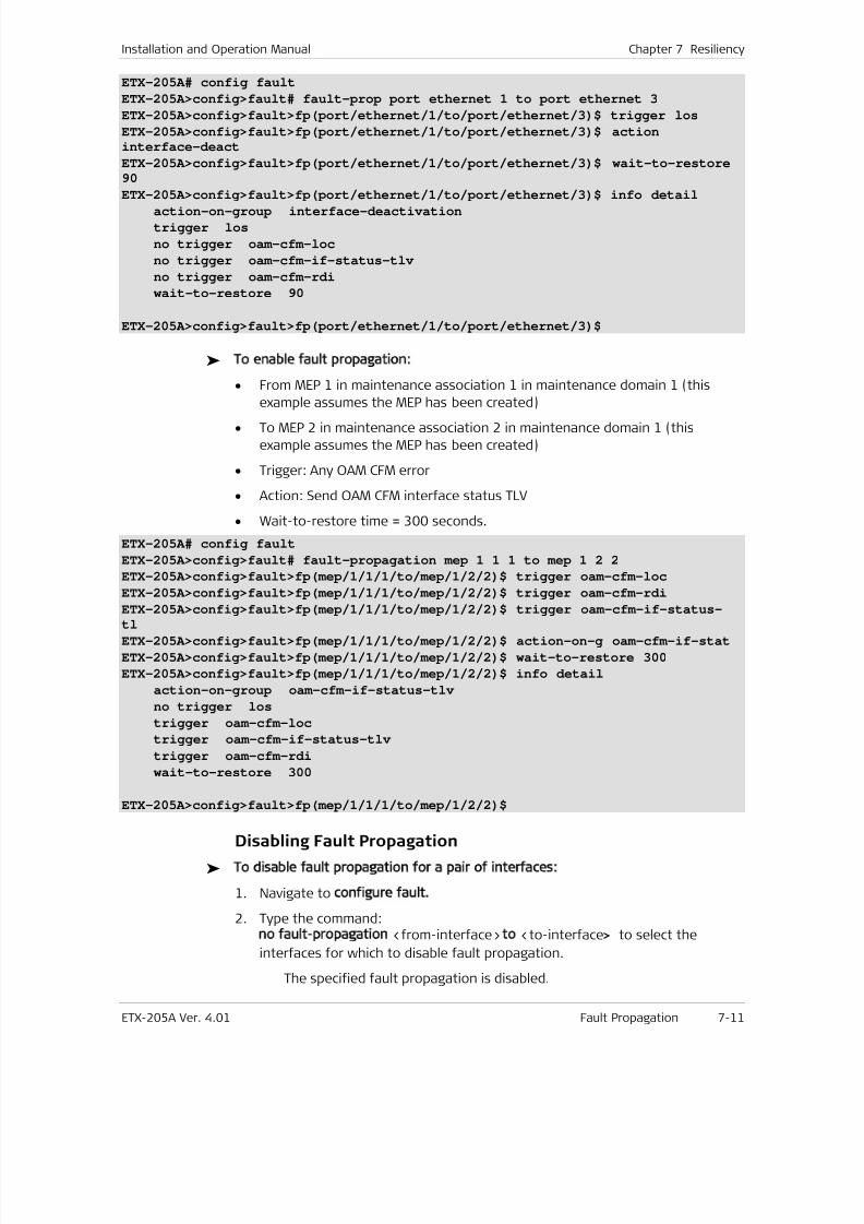
7/25/2019 Manual ETX-205A
http://slidepdf.com/reader/full/manual-etx-205a 177/409
Installation and Operation Manual Chapter 7 Resiliency
ETX-205A Ver. 4.01 Fault Propagation 7-11
ETX-205A# config fault
ETX-205A>config>fault# fault-prop port ethernet 1 to port ethernet 3
ETX-205A>config>fault>fp(port/ethernet/1/to/port/ethernet/3)$ trigger los
ETX-205A>config>fault>fp(port/ethernet/1/to/port/ethernet/3)$ actioninterface-deact
ETX-205A>config>fault>fp(port/ethernet/1/to/port/ethernet/3)$ wait-to-restore90
ETX-205A>config>fault>fp(port/ethernet/1/to/port/ethernet/3)$ info detail
action-on-group interface-deactivation
trigger los
no trigger oam-cfm-loc
no trigger oam-cfm-if-status-tlv
no trigger oam-cfm-rdi
wait-to-restore 90
ETX-205A>config>fault>fp(port/ethernet/1/to/port/ethernet/3)$
To enable fault propagation:
• From MEP 1 in maintenance association 1 in maintenance domain 1 (this
example assumes the MEP has been created)• To MEP 2 in maintenance association 2 in maintenance domain 1 (this
example assumes the MEP has been created)
• Trigger: Any OAM CFM error
• Action: Send OAM CFM interface status TLV
• Wait-to-restore time = 300 seconds.
ETX-205A# config fault
ETX-205A>config>fault# fault-propagation mep 1 1 1 to mep 1 2 2
ETX-205A>config>fault>fp(mep/1/1/1/to/mep/1/2/2)$ trigger oam-cfm-loc
ETX-205A>config>fault>fp(mep/1/1/1/to/mep/1/2/2)$ trigger oam-cfm-rdi
ETX-205A>config>fault>fp(mep/1/1/1/to/mep/1/2/2)$ trigger oam-cfm-if-status-tl
ETX-205A>config>fault>fp(mep/1/1/1/to/mep/1/2/2)$ action-on-g oam-cfm-if-stat
ETX-205A>config>fault>fp(mep/1/1/1/to/mep/1/2/2)$ wait-to-restore 300
ETX-205A>config>fault>fp(mep/1/1/1/to/mep/1/2/2)$ info detail
action-on-group oam-cfm-if-status-tlv
no trigger los
trigger oam-cfm-loc
trigger oam-cfm-if-status-tlv
trigger oam-cfm-rdi
wait-to-restore 300
ETX-205A>config>fault>fp(mep/1/1/1/to/mep/1/2/2)$
Disabling Fault Propagation
To disable fault propagation for a pair of interfaces:
1. Navigate to configure fault.
2. Type the command:no fault-propagation <from-interface> to <to-interface> to select the
interfaces for which to disable fault propagation.
The specified fault propagation is disabled.
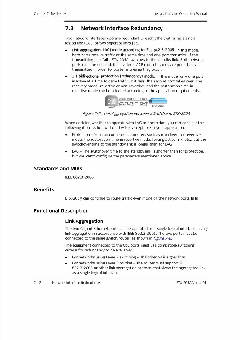
7/25/2019 Manual ETX-205A
http://slidepdf.com/reader/full/manual-etx-205a 178/409
Chapter 7 Resiliency Installation and Operation Manual
7-12 Network Interface Redundancy ETX-205A Ver. 4.01
7.3 Network Interface Redundancy
Two network interfaces operate redundant to each other, either as a single
logical link (LAG) or two separate links (1:1).
• Link aggregation (LAG) mode according to IEEE 802.3-2005. In this mode,
both ports receive traffic at the same time and one port transmits. If thetransmitting port fails, ETX-205A switches to the standby link. Both network
ports must be enabled. If activated, LACP control frames are periodically
transmitted in order to locate failures as they occur.
• 1:1 bidirectional protection (redundancy) mode. In this mode, only one port
is active at a time to carry traffic. If it fails, the second port takes over. The
recovery mode (revertive or non-revertive) and the restoration time in
revertive mode can be selected according to the application requirements.
Figure 7-7. Link Aggregation between a Switch and ETX-205A
When deciding whether to operate with LAG or protection, you can consider the
following if protection without LACP is acceptable in your application:
• Protection – You can configure parameters such as revertive/non-revertive
mode, the restoration time in revertive mode, forcing active link, etc., but the
switchover time to the standby link is longer than for LAG
• LAG – The switchover time to the standby link is shorter than for protection,
but you can’t configure the parameters mentioned above.
Standards and MIBsIEEE 802.3-2005
Benefits
ETX-205A can continue to route traffic even if one of the network ports fails.
Functional Description
Link Aggregation
The two Gigabit Ethernet ports can be operated as a single logical interface, using
link aggregation in accordance with IEEE 802.3-2005. The two ports must be
connected to the same switch/router, as shown in Figure 7-8 .
The equipment connected to the GbE ports must use compatible switching
criteria for redundancy to be available:
• For networks using Layer 2 switching – The criterion is signal loss
• For networks using Layer 3 routing – The router must support IEEE
802.3-2005 or other link aggregation protocol that views the aggregated link
as a single logical interface.
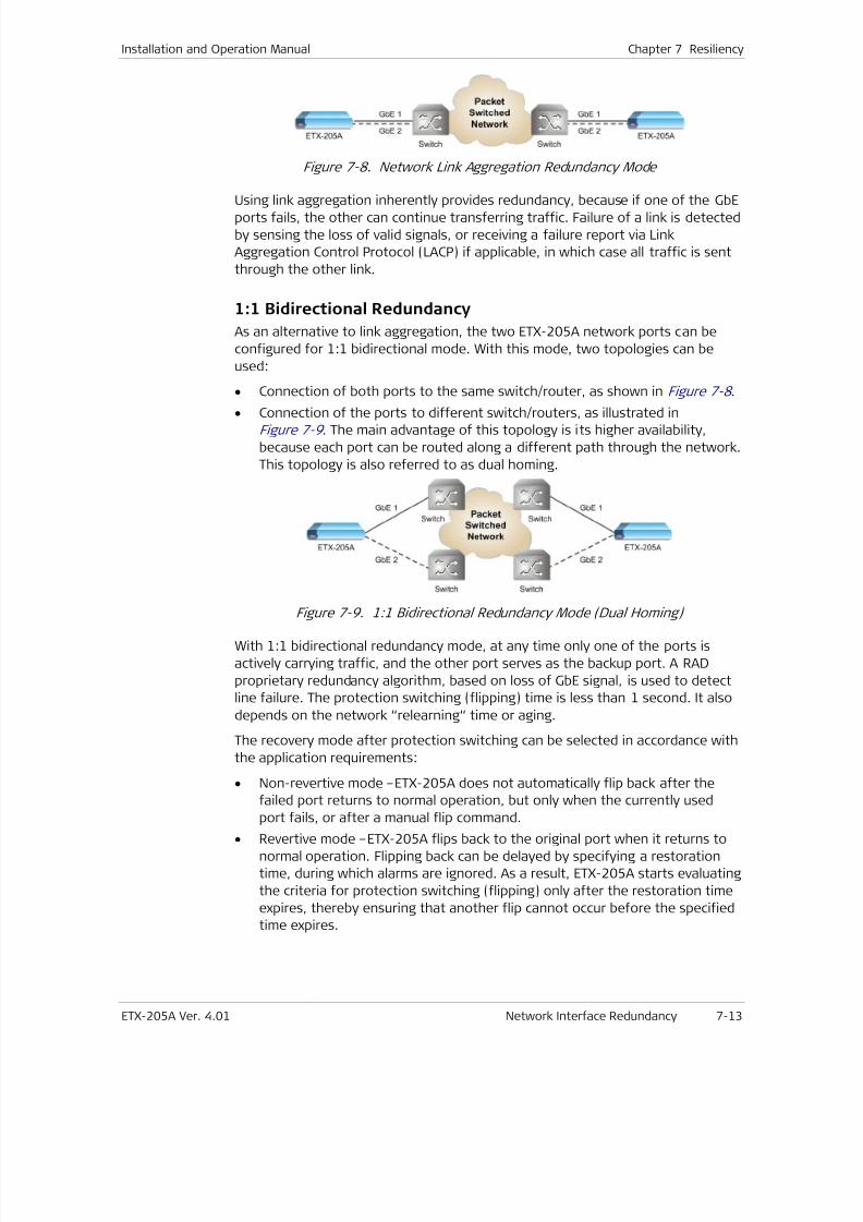
7/25/2019 Manual ETX-205A
http://slidepdf.com/reader/full/manual-etx-205a 179/409
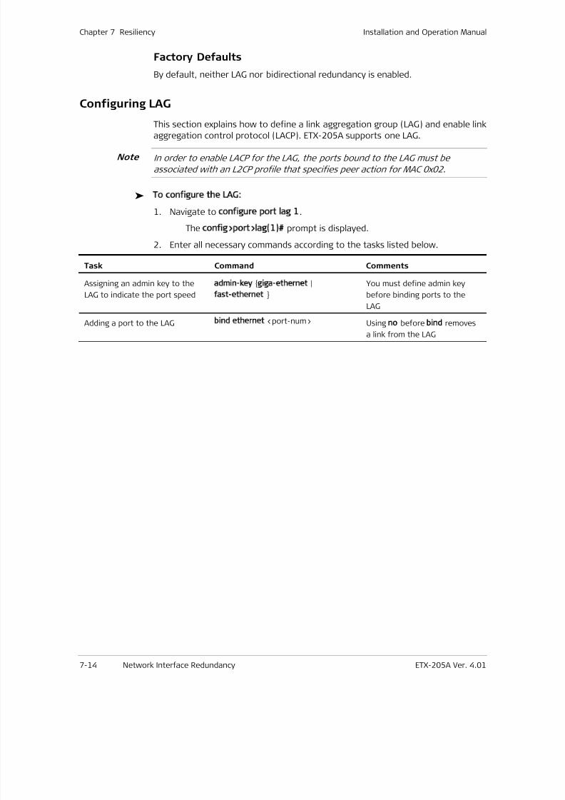
7/25/2019 Manual ETX-205A
http://slidepdf.com/reader/full/manual-etx-205a 180/409
Chapter 7 Resiliency Installation and Operation Manual
7-14 Network Interface Redundancy ETX-205A Ver. 4.01
Factory Defaults
By default, neither LAG nor bidirectional redundancy is enabled.
Configuring LAG
This section explains how to define a link aggregation group (LAG) and enable link
aggregation control protocol (LACP). ETX-205A supports one LAG.
In order to enable LACP for the LAG, the ports bound to the LAG must be
associated with an L2CP profile that specifies peer action for MAC 0x02.
To configure the LAG:
1. Navigate to configure port lag 1.
The config>port>lag(1)# prompt is displayed.
2. Enter all necessary commands according to the tasks listed below.
Task Command Comments
Assigning an admin key to the
LAG to indicate the port speed
admin-key giga-ethernet |
fast-ethernet
You must define admin key
before binding ports to the
LAG
Adding a port to the LAG bind ethernet <port-num> Using no before bind removes
a link from the LAG
Note
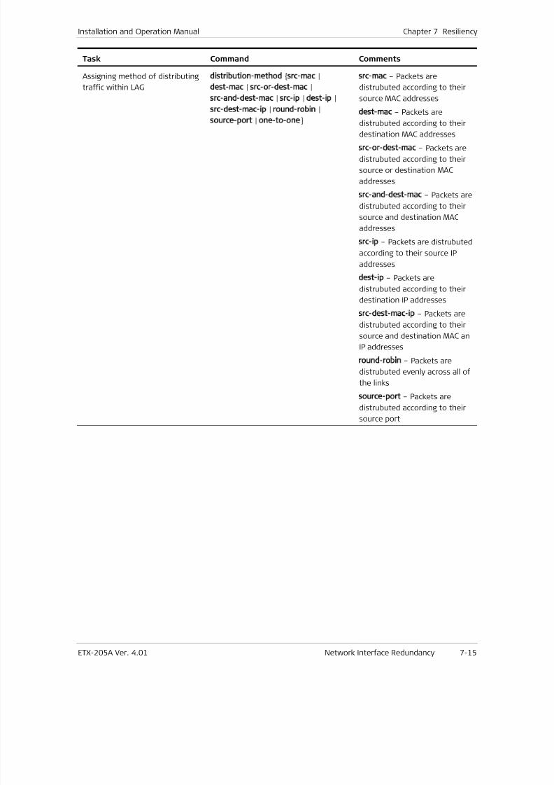
7/25/2019 Manual ETX-205A
http://slidepdf.com/reader/full/manual-etx-205a 181/409
Installation and Operation Manual Chapter 7 Resiliency
ETX-205A Ver. 4.01 Network Interface Redundancy 7-15
Task Command Comments
Assigning method of distributing
traffic within LAG
distribution-method src-mac |
dest-mac | src-or-dest-mac |
src-and-dest-mac | src-ip | dest-ip |
src-dest-mac-ip | round-robin |
source-port | one-to-one
src-mac – Packets are
distrubuted according to their
source MAC addresses
dest-mac – Packets are
distrubuted according to their
destination MAC addresses
src-or-dest-mac – Packets are
distrubuted according to their
source or destination MAC
addresses
src-and-dest-mac – Packets are
distrubuted according to their
source and destination MAC
addresses
src-ip – Packets are distrubuted
according to their source IP
addresses
dest-ip – Packets are
distrubuted according to their
destination IP addresses
src-dest-mac-ip – Packets are
distrubuted according to their
source and destination MAC an
IP addresses
round-robin – Packets are
distrubuted evenly across all of
the links
source-port – Packets are
distrubuted according to their
source port
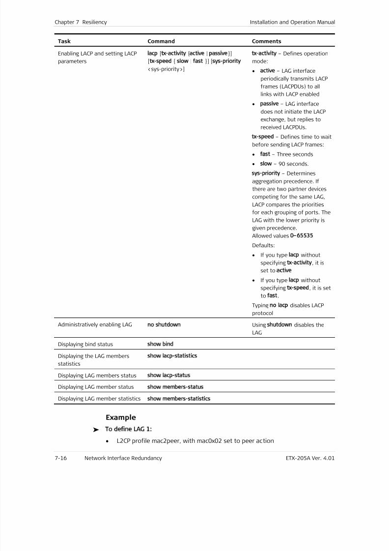
7/25/2019 Manual ETX-205A
http://slidepdf.com/reader/full/manual-etx-205a 182/409
Chapter 7 Resiliency Installation and Operation Manual
7-16 Network Interface Redundancy ETX-205A Ver. 4.01
Task Command Comments
Enabling LACP and setting LACP
parameters
lacp [tx-activity active | passive]
[tx-speed slow | fast ] [sys-priority
<sys-priority>]
tx-activity – Defines operation
mode:
• active – LAG interface
periodically transmits LACP
frames (LACPDUs) to all
links with LACP enabled
• passive – LAG interface
does not initiate the LACP
exchange, but replies to
received LACPDUs.
tx-speed – Defines time to wait
before sending LACP frames:
• fast – Three seconds
• slow – 90 seconds.
sys-priority – Determines
aggregation precedence. Ifthere are two partner devices
competing for the same LAG,
LACP compares the priorities
for each grouping of ports. The
LAG with the lower priority is
given precedence.
Allowed values 0–65535
Defaults:
• If you type lacp without
specifying tx-activity, it is
set to active
• If you type lacp without
specifying tx-speed, it is set
to fast.
Typing no lacp disables LACP
protocol
Administratively enabling LAGno shutdown Using shutdown disables the
LAG
Displaying bind status show bind
Displaying the LAG members
statistics
show lacp-statistics
Displaying LAG members status show lacp-status
Displaying LAG member statusshow members-status
Displaying LAG member statisticsshow members-statistics
Example
To define LAG 1:
• L2CP profile mac2peer, with mac0x02 set to peer action
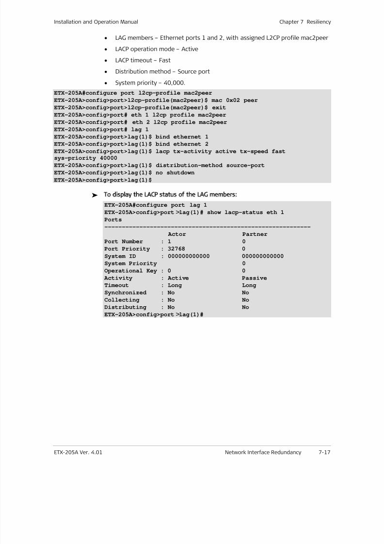
7/25/2019 Manual ETX-205A
http://slidepdf.com/reader/full/manual-etx-205a 183/409
Installation and Operation Manual Chapter 7 Resiliency
ETX-205A Ver. 4.01 Network Interface Redundancy 7-17
• LAG members – Ethernet ports 1 and 2, with assigned L2CP profile mac2peer
• LACP operation mode – Active
• LACP timeout – Fast
• Distribution method – Source port
• System priority – 40,000.
ETX-205A#configure port l2cp-profile mac2peer
ETX-205A>config>port>l2cp-profile(mac2peer)$ mac 0x02 peer
ETX-205A>config>port>l2cp-profile(mac2peer)$ exit
ETX-205A>config>port# eth 1 l2cp profile mac2peer
ETX-205A>config>port# eth 2 l2cp profile mac2peer
ETX-205A>config>port# lag 1
ETX-205A>config>port>lag(1)$ bind ethernet 1
ETX-205A>config>port>lag(1)$ bind ethernet 2
ETX-205A>config>port>lag(1)$ lacp tx-activity active tx-speed fastsys-priority 40000
ETX-205A>config>port>lag(1)$ distribution-method source-port
ETX-205A>config>port>lag(1)$ no shutdown
ETX-205A>config>port>lag(1)$
To display the LACP status of the LAG members:
ETX-205A#configure port lag 1ETX-205A>config>port>lag(1)# show lacp-status eth 1Ports
-----------------------------------------------------------
Actor Partner
Port Number : 1 0
Port Priority : 32768 0
System ID : 000000000000 000000000000
System Priority 0
Operational Key : 0 0 Activity : Active Passive
Timeout : Long Long
Synchronized : No No
Collecting : No No
Distributing : No No
ETX-205A>config>port>lag(1)#
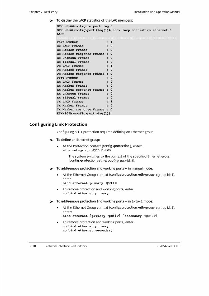
7/25/2019 Manual ETX-205A
http://slidepdf.com/reader/full/manual-etx-205a 184/409
Chapter 7 Resiliency Installation and Operation Manual
7-18 Network Interface Redundancy ETX-205A Ver. 4.01
To display the LACP statistics of the LAG members:
ETX-205A#configure port lag 1ETX-205A>config>port>lag(1)# show lacp-statistics ethernet 1LACP
---------------------------------------------------------------
Port Number : 1
Rx LACP Frames : 0
Rx Marker Frames : 0Rx Marker response Frames : 0
Rx Unknown Frames : 0
Rx Illegal Frames : 0
Tx LACP Frames : 1
Tx Marker Frames : 0
Tx Marker response Frames : 0
Port Number : 2
Rx LACP Frames : 0
Rx Marker Frames : 0
Rx Marker response Frames : 0
Rx Unknown Frames : 0
Rx Illegal Frames : 0Tx LACP Frames : 1
Tx Marker Frames : 0
Tx Marker response Frames : 0
ETX-205A>config>port>lag(1)#
Configuring Link Protection
Configuring a 1:1 protection requires defining an Ethernet group.
To define an Ethernet group:
•
At the Protection context (config>protection), enter:ethernet-group <gr oup- i d>
The system switches to the context of the specified Ethernet group
(config>protection>eth-group(<group-id>)).
To add/remove protection and working ports – in manual mode:
• At the Ethernet Group context (config>protection>eth-group(<group id>)),
enter bind ethernet primary <por t >
• To remove protection and working ports, enter:no bind ethernet primary
To add/remove protection and working ports – in 1–to–1 mode:
• At the Ethernet Group context (config>protection>eth-group(<group id>)),
enter: bind ethernet [ primary <por t >] [ secondary <por t >]
• To remove protection and working ports, enter:no bind ethernet primary
no bind ethernet secondary
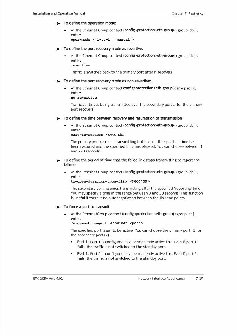
7/25/2019 Manual ETX-205A
http://slidepdf.com/reader/full/manual-etx-205a 185/409
Installation and Operation Manual Chapter 7 Resiliency
ETX-205A Ver. 4.01 Network Interface Redundancy 7-19
To define the operation mode:
• At the Ethernet Group context (config>protection>eth-group(<group id>)),
enter:oper-mode 1-to-1 | manual
To define the port recovery mode as revertive:
• At the Ethernet Group context (config>protection>eth-group(<group id>)),enter:revertive
Traffic is switched back to the primary port after it recovers.
To define the port recovery mode as non-revertive:
• At the Ethernet Group context config>protection>eth-group(<group id>)),
enter:no revertive
Traffic continues being transmitted over the secondary port after the primary
port recovers.
To define the time between recovery and resumption of transmission
• At the Ethernet Group context (config>protection>eth-group(<group id>)),
enterwait-to-restore <seconds>
The primary port resumes transmitting traffic once the specified time has
been restored and the specified time has elapsed. You can choose between 1
and 720 seconds.
To define the period of time that the failed link stops transmitting to report the
failure:
• At the Ethernet Group context (config>protection>eth-group(<group id>)),
entertx-down-duration-upon-flip <seconds>
The secondary port resumes transmitting after the specified ‘reporting’ time.
You may specify a time in the range between 0 and 30 seconds. This function
is useful if there is no autonegotiation between the link end points.
To force a port to transmit:
• At the EthernetGroup context (config>protection>eth-group(<group id>)),
enter:
force-active-port ether net <por t >
The specified port is set to be active. You can choose the primary port (1) or
the secondary port (2).
Port 1. Port 1 is configured as a permanently active link. Even if port 1
fails, the traffic is not switched to the standby port.
Port 2. Port 2 is configured as a permanently active link. Even if port 2
fails, the traffic is not switched to the standby port.
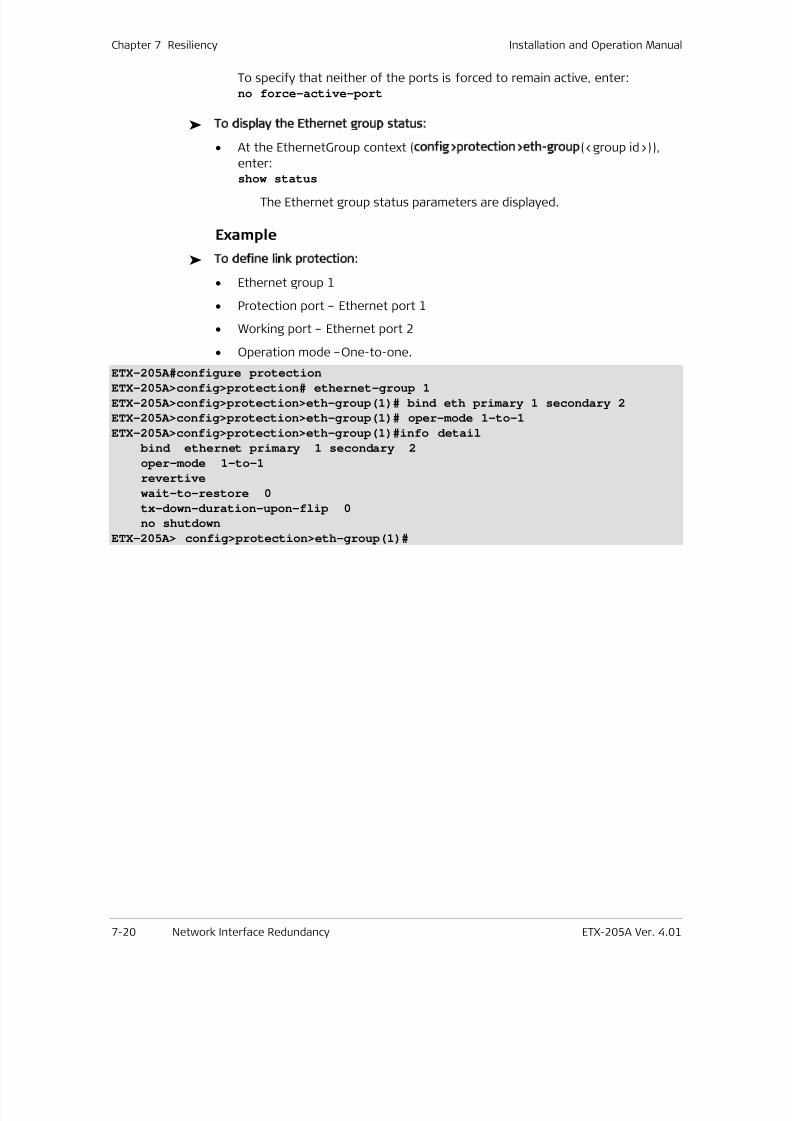
7/25/2019 Manual ETX-205A
http://slidepdf.com/reader/full/manual-etx-205a 186/409
Chapter 7 Resiliency Installation and Operation Manual
7-20 Network Interface Redundancy ETX-205A Ver. 4.01
To specify that neither of the ports is forced to remain active, enter:no force-active-port
To display the Ethernet group status:
• At the EthernetGroup context (config>protection>eth-group(<group id>)),
enter:show status
The Ethernet group status parameters are displayed.
Example
To define link protection:
• Ethernet group 1
• Protection port – Ethernet port 1
• Working port – Ethernet port 2
• Operation mode –One-to-one.
ETX-205A#configure protectionETX-205A>config>protection# ethernet-group 1
ETX-205A>config>protection>eth-group(1)# bind eth primary 1 secondary 2
ETX-205A>config>protection>eth-group(1)# oper-mode 1-to-1
ETX-205A>config>protection>eth-group(1)#info detail
bind ethernet primary 1 secondary 2
oper-mode 1-to-1
revertive
wait-to-restore 0
tx-down-duration-upon-flip 0
no shutdown
ETX-205A> config>protection>eth-group(1)#
7/25/2019 Manual ETX-205A
http://slidepdf.com/reader/full/manual-etx-205a 187/409
ETX-205A Ver. 4.01 Flows 8-1
Chapter 8
Networking
This chapter describes networking features:
• Flows
• Layer-2 Control Processing
• OAM
• Quality of Service (QoS)
• Router .
8.1 Flows
ETX-205A supports up to 192 unidirectional Ethernet flows, which can be used to
provide E-line or E-LAN service delivery over Metro Ethernet networks. Each
Ethernet flow is unidirectional and connects two ports.
This section explains how to define the flows according to specific criteria such as
VLAN. You can use classifier profiles to specify the criteria for flows. The
classification is per port and is applied to the ingress port of the flow.
You can configure a unidirectional hub (UDH) by defining up to five flows with the
same ingress port, classifier profile, and policer aggregate, and different egress
ports. Up to seven UDH groups can be defined per device. The egress ports mustbe physical Ethernet ports, not virtual ports such as SVI, ETP, etc. Only one
queue-mapping profile and one marking profile can be used for the flows in a
UDH group, however VLAN tag editing can be different in the different flows.
Standards
IEEE 802.3x
Benefits
The user traffic can be classified into different Ethernet flows (EVC.CoS) toprovide services in a flexible manner.
Functional Description
Packets can be classified by means of their VLAN IDs and other criteria, fully
specified in Defining Classifier Profiles .
Classifications that apply to the same port are allowed in the combinations
shown in Table 8-9 . The priority shown is used to determine which classification
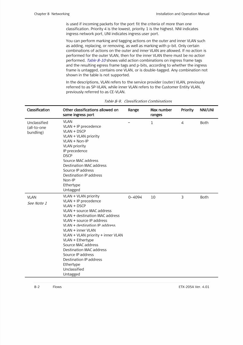
7/25/2019 Manual ETX-205A
http://slidepdf.com/reader/full/manual-etx-205a 188/409
Chapter 8 Networking Installation and Operation Manual
8-2 Flows ETX-205A Ver. 4.01
is used if incoming packets for the port fit the criteria of more than one
classification. Priority 4 is the lowest, priority 1 is the highest. NNI indicates
ingress network port, UNI indicates ingress user port.
You can perform marking and tagging actions on the outer and inner VLAN such
as adding, replacing, or removing, as well as marking with p-bit. Only certain
combinations of actions on the outer and inner VLAN are allowed. If no action is
performed for the outer VLAN, then for the inner VLAN there must be no actionperformed. Table 8-10 shows valid action combinations on ingress frame tags
and the resulting egress frame tags and p-bits, according to whether the ingress
frame is untagged, contains one VLAN, or is double-tagged. Any combination not
shown in the table is not supported.
In the descriptions, VLAN refers to the service provider (outer) VLAN, previously
referred to as SP-VLAN, while inner VLAN refers to the Customer Entity VLAN,
previously referred to as CE-VLAN.
Table 8-9. Classification Combinations
Classification Other classifications allowed on
same ingress port
Range Max number
ranges
Priority NNI/UNI
Unclassified
(all-to-one
bundling)
VLAN
VLAN + IP precedence
VLAN + DSCP
VLAN + VLAN priority
VLAN + Non-IP
VLAN priority
IP precedence
DSCP
Source MAC address
Destination MAC address
Source IP addressDestination IP address
Non-IP
Ethertype
Untagged
– 1 4 Both
VLAN
See Note 1
VLAN + VLAN priority
VLAN + IP precedence
VLAN + DSCP
VLAN + source MAC address
VLAN + destination MAC address
VLAN + source IP address
VLAN + destination IP address
VLAN + inner VLANVLAN + VLAN priority + inner VLAN
VLAN + Ethertype
Source MAC address
Destination MAC address
Source IP address
Destination IP address
Ethertype
Unclassified
Untagged
0–4094 10 3 Both
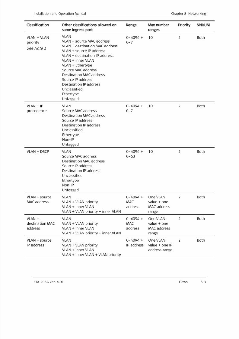
7/25/2019 Manual ETX-205A
http://slidepdf.com/reader/full/manual-etx-205a 189/409
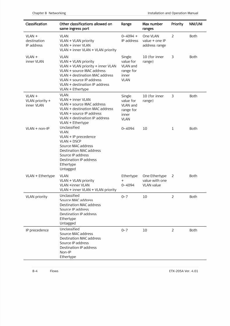
7/25/2019 Manual ETX-205A
http://slidepdf.com/reader/full/manual-etx-205a 190/409
Chapter 8 Networking Installation and Operation Manual
8-4 Flows ETX-205A Ver. 4.01
Classification Other classifications allowed on
same ingress port
Range Max number
ranges
Priority NNI/UNI
VLAN +
destination
IP address
VLAN
VLAN + VLAN priority
VLAN + inner VLAN
VLAN + inner VLAN + VLAN priority
0–4094 +
IP address
One VLAN
value + one IP
address range
2 Both
VLAN +
inner VLAN
VLAN
VLAN + VLAN priority
VLAN + VLAN priority + inner VLAN
VLAN + source MAC address
VLAN + destination MAC address
VLAN + source IP address
VLAN + destination IP address
VLAN + Ethertype
Single
value for
VLAN and
range for
inner
VLAN
10 (for inner
range)
3 Both
VLAN +
VLAN priority +
inner VLAN
VLAN
VLAN + inner VLAN
VLAN + source MAC address
VLAN + destination MAC addressVLAN + source IP address
VLAN + destination IP address
VLAN + Ethertype
Single
value for
VLAN and
range for
inner
VLAN
10 (for inner
range)
3 Both
VLAN + non-IP Unclassified
VLAN
VLAN + IP precedence
VLAN + DSCP
Source MAC address
Destination MAC address
Source IP address
Destination IP address
Ethertype
Untagged
0–4094 10 1 Both
VLAN + Ethertype VLAN
VLAN + VLAN priority
VLAN +inner VLAN
VLAN + inner VLAN + VLAN priority
Ethertype
+
0–4094
One Ethertype
value with one
VLAN value
2 Both
VLAN priority Unclassified
Source MAC address
Destination MAC address
Source IP address
Destination IP address
Ethertype
Untagged
0–7 10 2 Both
IP precedence Unclassified
Source MAC address
Destination MAC address
Source IP address
Destination IP address
Non-IP
Ethertype
0–7 10 2 Both
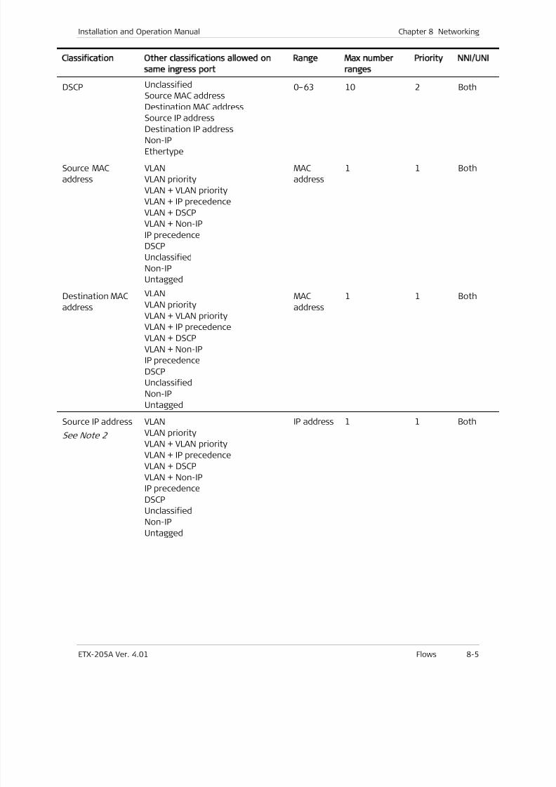
7/25/2019 Manual ETX-205A
http://slidepdf.com/reader/full/manual-etx-205a 191/409
Installation and Operation Manual Chapter 8 Networking
ETX-205A Ver. 4.01 Flows 8-5
Classification Other classifications allowed on
same ingress port
Range Max number
ranges
Priority NNI/UNI
DSCP Unclassified
Source MAC address
Destination MAC address
Source IP address
Destination IP addressNon-IP
Ethertype
0–63 10 2 Both
Source MAC
address
VLAN
VLAN priority
VLAN + VLAN priority
VLAN + IP precedence
VLAN + DSCP
VLAN + Non-IP
IP precedence
DSCP
UnclassifiedNon-IP
Untagged
MAC
address
1 1 Both
Destination MAC
address
VLAN
VLAN priority
VLAN + VLAN priority
VLAN + IP precedence
VLAN + DSCP
VLAN + Non-IP
IP precedence
DSCP
Unclassified
Non-IPUntagged
MAC
address
1 1 Both
Source IP address
See Note 2
VLAN
VLAN priority
VLAN + VLAN priority
VLAN + IP precedence
VLAN + DSCP
VLAN + Non-IP
IP precedence
DSCP
Unclassified
Non-IPUntagged
IP address 1 1 Both
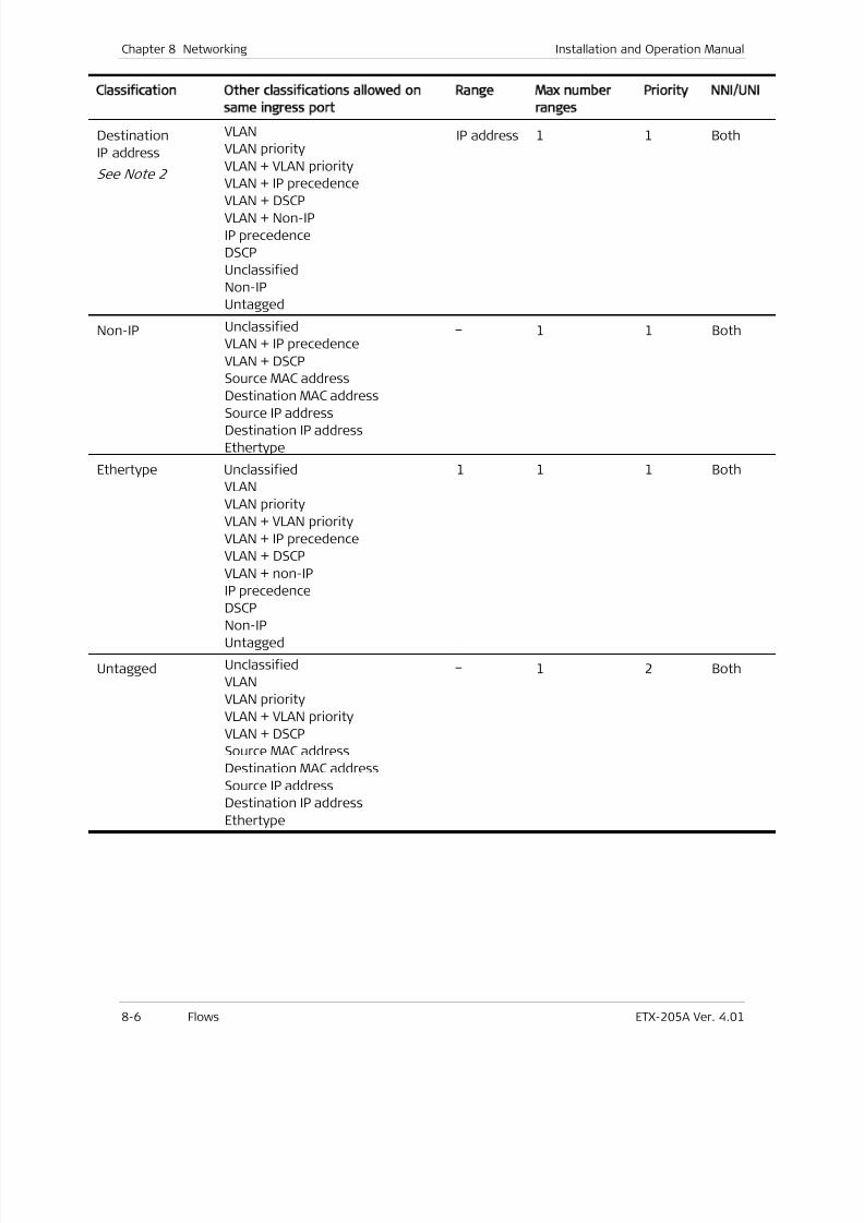
7/25/2019 Manual ETX-205A
http://slidepdf.com/reader/full/manual-etx-205a 192/409
Chapter 8 Networking Installation and Operation Manual
8-6 Flows ETX-205A Ver. 4.01
Classification Other classifications allowed on
same ingress port
Range Max number
ranges
Priority NNI/UNI
Destination
IP address
See Note 2
VLAN
VLAN priority
VLAN + VLAN priority
VLAN + IP precedence
VLAN + DSCPVLAN + Non-IP
IP precedence
DSCP
Unclassified
Non-IP
Untagged
IP address 1 1 Both
Non-IP Unclassified
VLAN + IP precedence
VLAN + DSCP
Source MAC address
Destination MAC address
Source IP address
Destination IP address
Ethertype
– 1 1 Both
Ethertype Unclassified
VLAN
VLAN priority
VLAN + VLAN priority
VLAN + IP precedence
VLAN + DSCP
VLAN + non-IP
IP precedence
DSCPNon-IP
Untagged
1 1 1 Both
Untagged Unclassified
VLAN
VLAN priority
VLAN + VLAN priority
VLAN + DSCP
Source MAC address
Destination MAC address
Source IP address
Destination IP address
Ethertype
– 1 2 Both
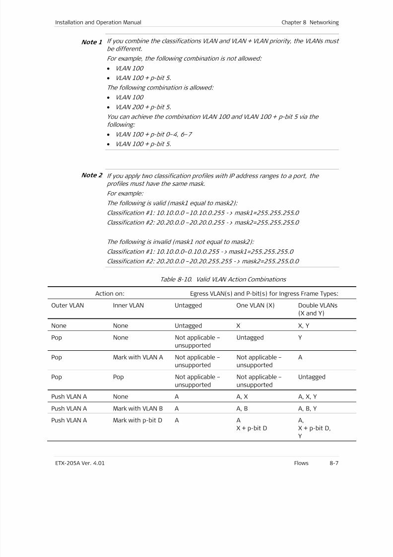
7/25/2019 Manual ETX-205A
http://slidepdf.com/reader/full/manual-etx-205a 193/409
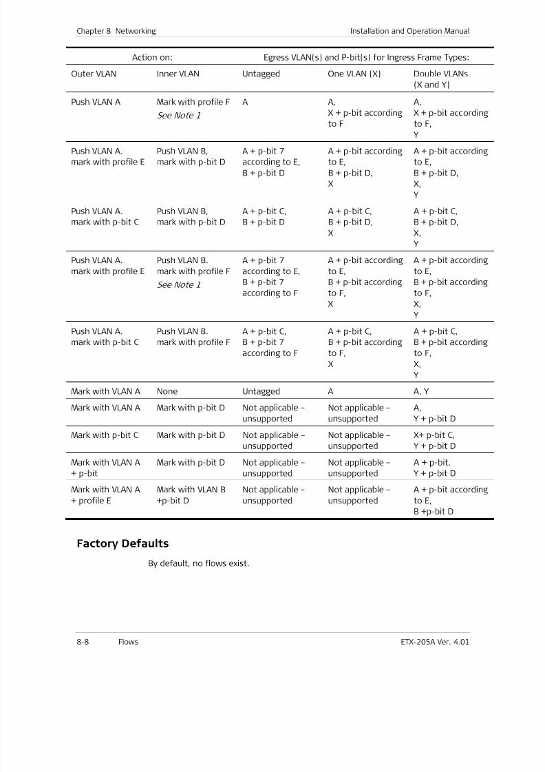
7/25/2019 Manual ETX-205A
http://slidepdf.com/reader/full/manual-etx-205a 194/409
Chapter 8 Networking Installation and Operation Manual
8-8 Flows ETX-205A Ver. 4.01
Action on: Egress VLAN(s) and P-bit(s) for Ingress Frame Types:
Outer VLAN Inner VLAN Untagged One VLAN (X) Double VLANs
(X and Y)
Push VLAN A Mark with profile F
See Note 1
A A,
X + p-bit according
to F
A,
X + p-bit according
to F,Y
Push VLAN A.
mark with profile E
Push VLAN B,
mark with p-bit D
A + p-bit 7
according to E,
B + p-bit D
A + p-bit according
to E,
B + p-bit D,
X
A + p-bit according
to E,
B + p-bit D,
X,
Y
Push VLAN A.
mark with p-bit C
Push VLAN B,
mark with p-bit D
A + p-bit C,
B + p-bit D
A + p-bit C,
B + p-bit D,
X
A + p-bit C,
B + p-bit D,
X,
Y
Push VLAN A.
mark with profile E
Push VLAN B.
mark with profile F
See Note 1
A + p-bit 7
according to E,
B + p-bit 7
according to F
A + p-bit according
to E,
B + p-bit according
to F,
X
A + p-bit according
to E,
B + p-bit according
to F,
X,
Y
Push VLAN A.
mark with p-bit C
Push VLAN B.
mark with profile F
A + p-bit C,
B + p-bit 7
according to F
A + p-bit C,
B + p-bit according
to F,
X
A + p-bit C,
B + p-bit according
to F,
X,
Y
Mark with VLAN A None Untagged A A, Y
Mark with VLAN A Mark with p-bit D Not applicable –
unsupported
Not applicable –
unsupported
A,
Y + p-bit D
Mark with p-bit C Mark with p-bit D Not applicable –
unsupported
Not applicable –
unsupported
X+ p-bit C,
Y + p-bit D
Mark with VLAN A
+ p-bit
Mark with p-bit D Not applicable –
unsupported
Not applicable –
unsupported
A + p-bit,
Y + p-bit D
Mark with VLAN A
+ profile E
Mark with VLAN B
+p-bit D
Not applicable –
unsupported
Not applicable –
unsupported
A + p-bit according
to E,
B +p-bit D
Factory Defaults
By default, no flows exist.
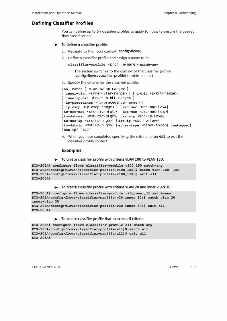
7/25/2019 Manual ETX-205A
http://slidepdf.com/reader/full/manual-etx-205a 195/409
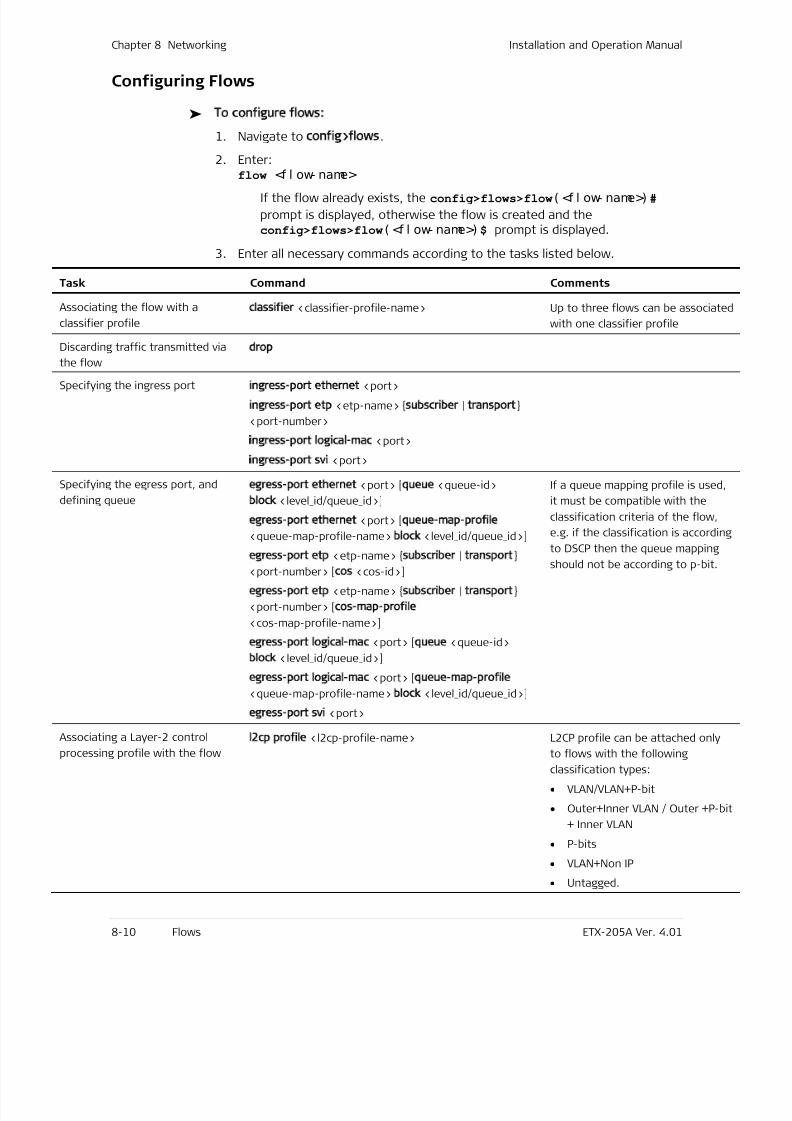
7/25/2019 Manual ETX-205A
http://slidepdf.com/reader/full/manual-etx-205a 196/409
Chapter 8 Networking Installation and Operation Manual
8-10 Flows ETX-205A Ver. 4.01
Configuring Flows
To configure flows:
1. Navigate to config>flows.
2. Enter:flow <f l ow- name>
If the flow already exists, the config>flows>flow( <f l ow- name>) #
prompt is displayed, otherwise the flow is created and theconfig>flows>flow( <f l ow- name>) $ prompt is displayed.
3. Enter all necessary commands according to the tasks listed below.
Task Command Comments
Associating the flow with a
classifier profile
classifier <classifier-profile-name> Up to three flows can be associate
with one classifier profile
Discarding traffic transmitted via
the flow
drop
Specifying the ingress portingress-port ethernet <port>
ingress-port etp <etp-name> subscriber | transport
<port-number>
ingress-port logical-mac <port>
ingress-port svi <port>
Specifying the egress port, and
defining queue
egress-port ethernet <port> [queue <queue-id>
block <level_id/queue_id>]
egress-port ethernet <port> [queue-map-profile
<queue-map-profile-name> block <level_id/queue_id>]
egress-port etp <etp-name> subscriber | transport<port-number> [cos <cos-id>]
egress-port etp <etp-name> subscriber | transport
<port-number> [cos-map-profile
<cos-map-profile-name>]
egress-port logical-mac <port> [queue <queue-id>
block <level_id/queue_id>]
egress-port logical-mac <port> [queue-map-profile
<queue-map-profile-name> block <level_id/queue_id>]
egress-port svi <port>
If a queue mapping profile is used
it must be compatible with the
classification criteria of the flow,
e.g. if the classification is accordin
to DSCP then the queue mapping
should not be according to p-bit.
Associating a Layer-2 control
processing profile with the flow
l2cp profile <l2cp-profile-name> L2CP profile can be attached only
to flows with the following
classification types:
• VLAN/VLAN+P-bit
• Outer+Inner VLAN / Outer +P-b
+ Inner VLAN
• P-bits
• VLAN+Non IP
• Untagged.
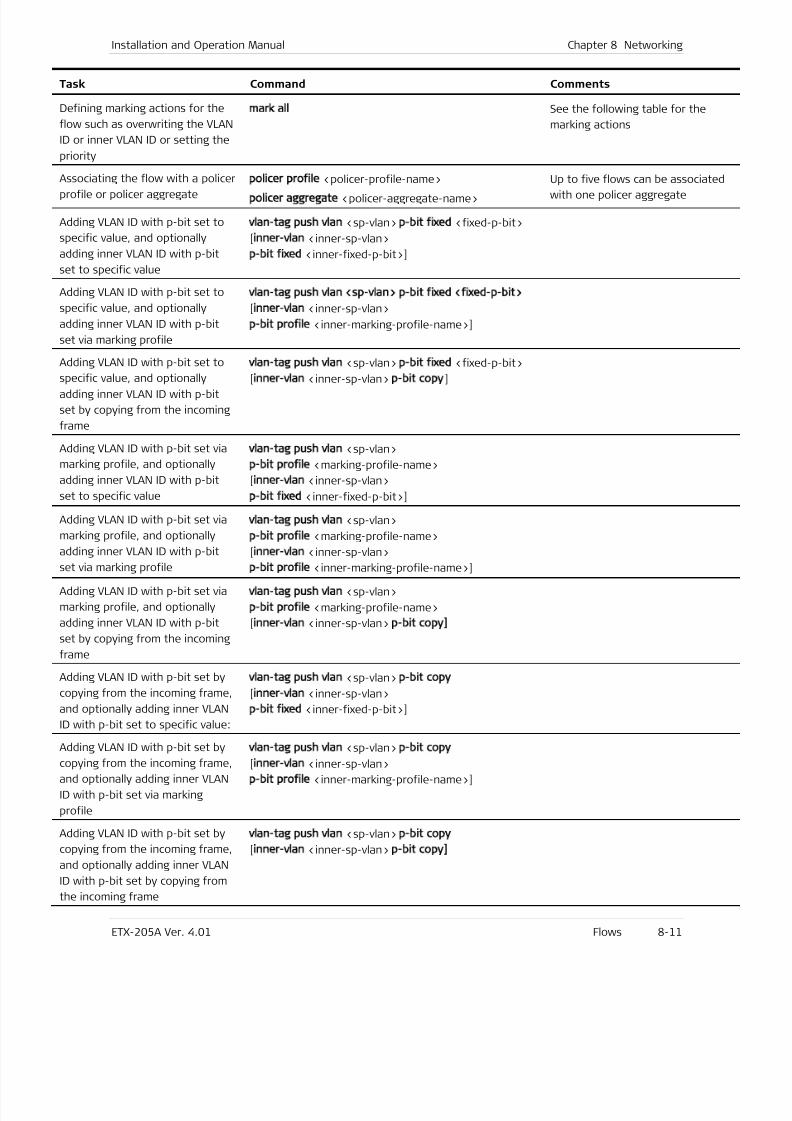
7/25/2019 Manual ETX-205A
http://slidepdf.com/reader/full/manual-etx-205a 197/409
Installation and Operation Manual Chapter 8 Networking
ETX-205A Ver. 4.01 Flows 8-11
Task Command Comments
Defining marking actions for the
flow such as overwriting the VLAN
ID or inner VLAN ID or setting the
priority
mark all See the following table for the
marking actions
Associating the flow with a policer
profile or policer aggregate
policer profile <policer-profile-name>
policer aggregate <policer-aggregate-name>
Up to five flows can be associated
with one policer aggregate
Adding VLAN ID with p-bit set to
specific value, and optionally
adding inner VLAN ID with p-bit
set to specific value
vlan-tag push vlan <sp-vlan> p-bit fixed <fixed-p-bit>
[inner-vlan <inner-sp-vlan>
p-bit fixed <inner-fixed-p-bit>]
Adding VLAN ID with p-bit set to
specific value, and optionally
adding inner VLAN ID with p-bit
set via marking profile
vlan-tag push vlan <sp-vlan> p-bit fixed <fixed-p-bit>
[inner-vlan <inner-sp-vlan>
p-bit profile <inner-marking-profile-name>]
Adding VLAN ID with p-bit set to
specific value, and optionally
adding inner VLAN ID with p-bit
set by copying from the incoming
frame
vlan-tag push vlan <sp-vlan> p-bit fixed <fixed-p-bit>
[inner-vlan <inner-sp-vlan> p-bit copy]
Adding VLAN ID with p-bit set via
marking profile, and optionally
adding inner VLAN ID with p-bit
set to specific value
vlan-tag push vlan <sp-vlan>
p-bit profile <marking-profile-name>
[inner-vlan <inner-sp-vlan>
p-bit fixed <inner-fixed-p-bit>]
Adding VLAN ID with p-bit set via
marking profile, and optionally
adding inner VLAN ID with p-bit
set via marking profile
vlan-tag push vlan <sp-vlan>
p-bit profile <marking-profile-name>
[inner-vlan <inner-sp-vlan>
p-bit profile <inner-marking-profile-name>]
Adding VLAN ID with p-bit set via
marking profile, and optionally
adding inner VLAN ID with p-bit
set by copying from the incoming
frame
vlan-tag push vlan <sp-vlan>
p-bit profile <marking-profile-name>
[inner-vlan <inner-sp-vlan> p-bit copy]
Adding VLAN ID with p-bit set by
copying from the incoming frame,
and optionally adding inner VLAN
ID with p-bit set to specific value:
vlan-tag push vlan <sp-vlan> p-bit copy
[inner-vlan <inner-sp-vlan>
p-bit fixed <inner-fixed-p-bit>]
Adding VLAN ID with p-bit set bycopying from the incoming frame,
and optionally adding inner VLAN
ID with p-bit set via marking
profile
vlan-tag push vlan <sp-vlan> p-bit copy
[inner-vlan <inner-sp-vlan>
p-bit profile <inner-marking-profile-name>]
Adding VLAN ID with p-bit set by
copying from the incoming frame,
and optionally adding inner VLAN
ID with p-bit set by copying from
the incoming frame
vlan-tag push vlan <sp-vlan> p-bit copy
[inner-vlan <inner-sp-vlan> p-bit copy]
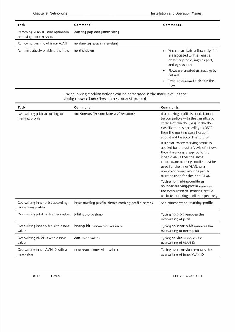
7/25/2019 Manual ETX-205A
http://slidepdf.com/reader/full/manual-etx-205a 198/409
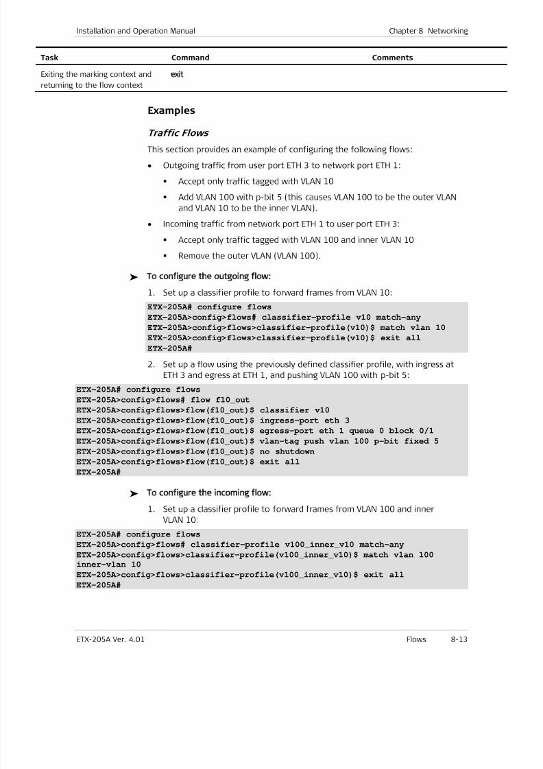
7/25/2019 Manual ETX-205A
http://slidepdf.com/reader/full/manual-etx-205a 199/409
Installation and Operation Manual Chapter 8 Networking
ETX-205A Ver. 4.01 Flows 8-13
Task Command Comments
Exiting the marking context and
returning to the flow context
exit
Examples
Traffic Flows
This section provides an example of configuring the following flows:
• Outgoing traffic from user port ETH 3 to network port ETH 1:
Accept only traffic tagged with VLAN 10
Add VLAN 100 with p-bit 5 (this causes VLAN 100 to be the outer VLAN
and VLAN 10 to be the inner VLAN).
• Incoming traffic from network port ETH 1 to user port ETH 3:
Accept only traffic tagged with VLAN 100 and inner VLAN 10
Remove the outer VLAN (VLAN 100).
To configure the outgoing flow:
1. Set up a classifier profile to forward frames from VLAN 10:
ETX-205A# configure flows
ETX-205A>config>flows# classifier-profile v10 match-any
ETX-205A>config>flows>classifier-profile(v10)$ match vlan 10
ETX-205A>config>flows>classifier-profile(v10)$ exit all
ETX-205A#
2. Set up a flow using the previously defined classifier profile, with ingress at
ETH 3 and egress at ETH 1, and pushing VLAN 100 with p-bit 5:
ETX-205A# configure flows
ETX-205A>config>flows# flow f10_out
ETX-205A>config>flows>flow(f10_out)$ classifier v10
ETX-205A>config>flows>flow(f10_out)$ ingress-port eth 3
ETX-205A>config>flows>flow(f10_out)$ egress-port eth 1 queue 0 block 0/1
ETX-205A>config>flows>flow(f10_out)$ vlan-tag push vlan 100 p-bit fixed 5
ETX-205A>config>flows>flow(f10_out)$ no shutdown
ETX-205A>config>flows>flow(f10_out)$ exit all
ETX-205A#
To configure the incoming flow:
1. Set up a classifier profile to forward frames from VLAN 100 and innerVLAN 10:
ETX-205A# configure flows
ETX-205A>config>flows# classifier-profile v100_inner_v10 match-any
ETX-205A>config>flows>classifier-profile(v100_inner_v10)$ match vlan 100
inner-vlan 10
ETX-205A>config>flows>classifier-profile(v100_inner_v10)$ exit all
ETX-205A#
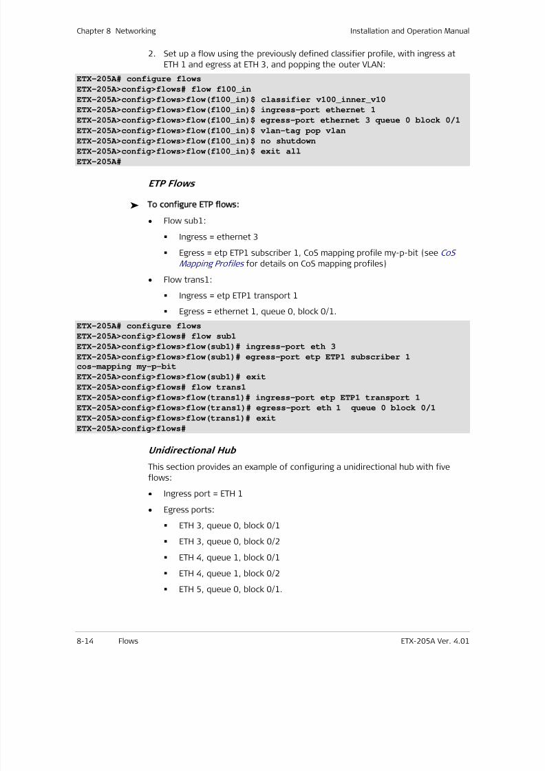
7/25/2019 Manual ETX-205A
http://slidepdf.com/reader/full/manual-etx-205a 200/409
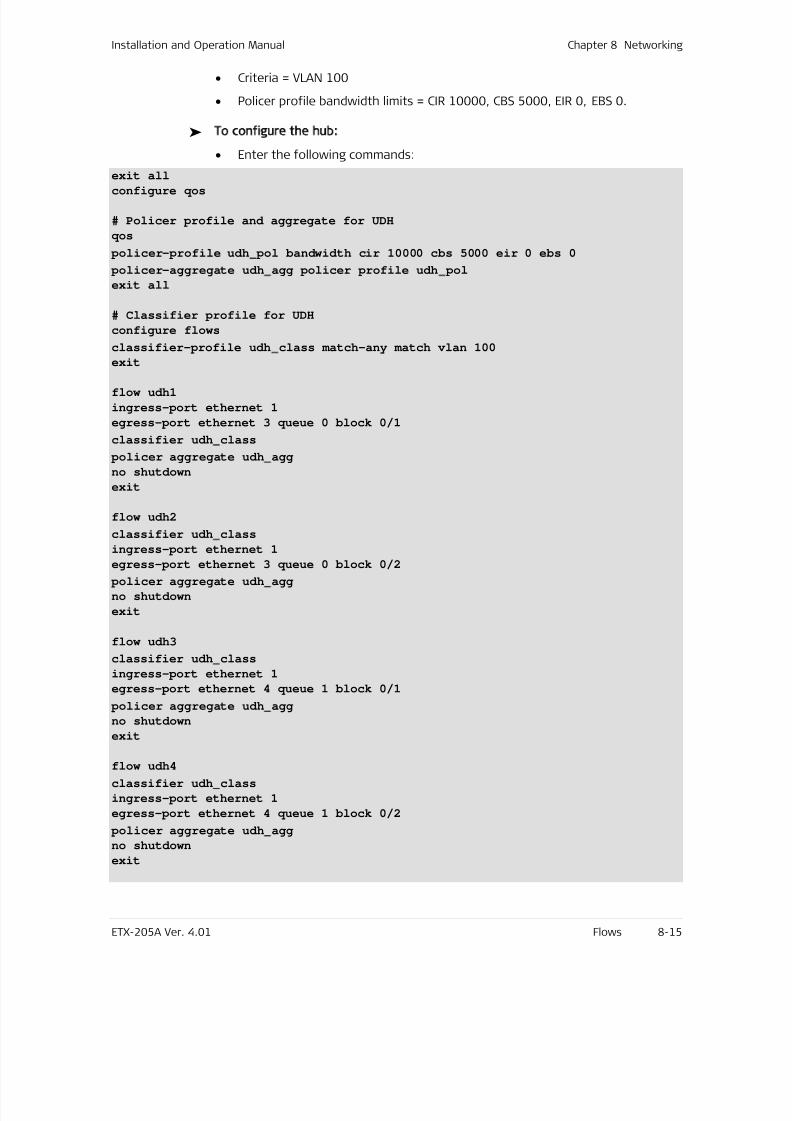
7/25/2019 Manual ETX-205A
http://slidepdf.com/reader/full/manual-etx-205a 201/409
Installation and Operation Manual Chapter 8 Networking
ETX-205A Ver. 4.01 Flows 8-15
• Criteria = VLAN 100
• Policer profile bandwidth limits = CIR 10000, CBS 5000, EIR 0, EBS 0.
To configure the hub:
• Enter the following commands:
exit all
configure qos
# Policer profile and aggregate for UDH
qos
policer-profile udh pol bandwidth cir 10000 cbs 5000 eir 0 ebs 0
policer-aggregate udh agg policer profile udh pol
exit all
# Classifier profile for UDH
configure flows
classifier-profile udh class match-any match vlan 100
exit
flow udh1
ingress-port ethernet 1
egress-port ethernet 3 queue 0 block 0/1
classifier udh class
policer aggregate udh agg
no shutdown
exit
flow udh2
classifier udh class
ingress-port ethernet 1
egress-port ethernet 3 queue 0 block 0/2
policer aggregate udh agg
no shutdown
exit
flow udh3
classifier udh class
ingress-port ethernet 1
egress-port ethernet 4 queue 1 block 0/1
policer aggregate udh agg
no shutdown
exit
flow udh4
classifier udh class
ingress-port ethernet 1
egress-port ethernet 4 queue 1 block 0/2
policer aggregate udh agg
no shutdown
exit
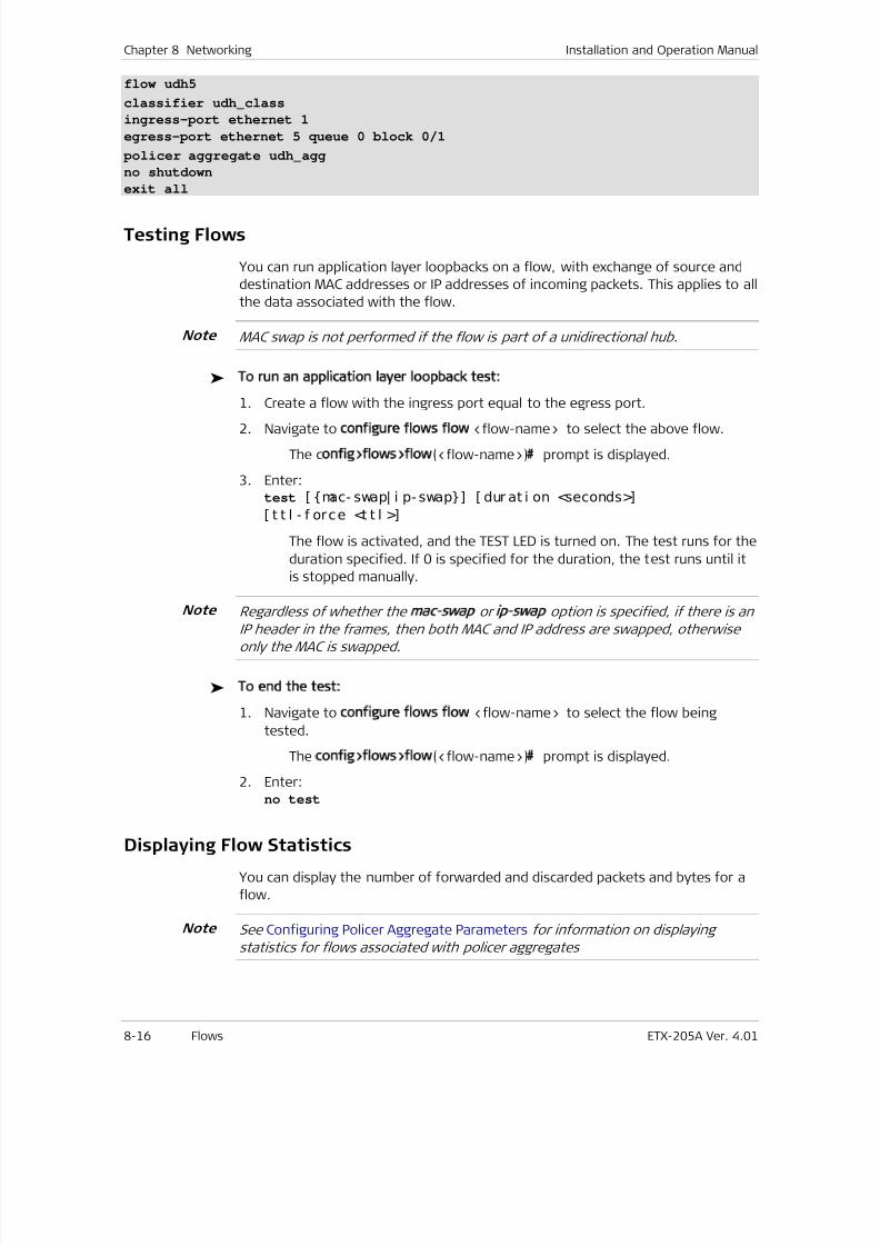
7/25/2019 Manual ETX-205A
http://slidepdf.com/reader/full/manual-etx-205a 202/409
Chapter 8 Networking Installation and Operation Manual
8-16 Flows ETX-205A Ver. 4.01
flow udh5
classifier udh class
ingress-port ethernet 1
egress-port ethernet 5 queue 0 block 0/1
policer aggregate udh agg
no shutdown
exit all
Testing Flows
You can run application layer loopbacks on a flow, with exchange of source and
destination MAC addresses or IP addresses of incoming packets. This applies to all
the data associated with the flow.
MAC swap is not performed if the flow is part of a unidirectional hub.
To run an application layer loopback test:
1. Create a flow with the ingress port equal to the egress port.
2. Navigate to configure flows flow <flow-name> to select the above flow.
The config>flows>flow(<flow-name>)# prompt is displayed.
3. Enter: test [ mac- swap| i p- swap] [ dur at i on <seconds>]
[ t t l - f orce <t t l >]
The flow is activated, and the TEST LED is turned on. The test runs for the
duration specified. If 0 is specified for the duration, the test runs until it
is stopped manually.
Regardless of whether the mac swap or ip swap option is specified, if there is an
IP header in the frames, then both MAC and IP address are swapped, otherwise
only the MAC is swapped.
To end the test:
1. Navigate to configure flows flow <flow-name> to select the flow being
tested.
The config>flows>flow(<flow-name>)# prompt is displayed.
2. Enter:no test
Displaying Flow Statistics
You can display the number of forwarded and discarded packets and bytes for a
flow.
See Configuring Policer Aggregate Parameters for information on displaying
statistics for flows associated with policer aggregates
Note
Note
Note

7/25/2019 Manual ETX-205A
http://slidepdf.com/reader/full/manual-etx-205a 203/409
Installation and Operation Manual Chapter 8 Networking
ETX-205A Ver. 4.01 Flows 8-17
To display the statistics for a flow:
• At the relevant flow context (config>flows>flow(<flow-id>)), enter:show statistics running
Flow statistics are displayed.
To clear the statistics for a flow:
• At the relevant flow context (config>flows>flow(<flow-id>)), enter:clear-statistics
The statistics for the flow are cleared.
Example
This example uses flow f10 _out, created in the traffic flow example.Note
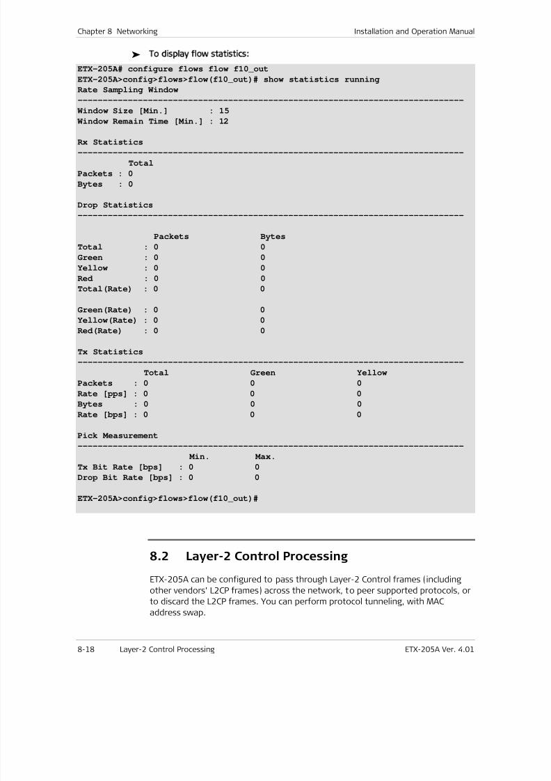
7/25/2019 Manual ETX-205A
http://slidepdf.com/reader/full/manual-etx-205a 204/409
7/25/2019 Manual ETX-205A
http://slidepdf.com/reader/full/manual-etx-205a 205/409
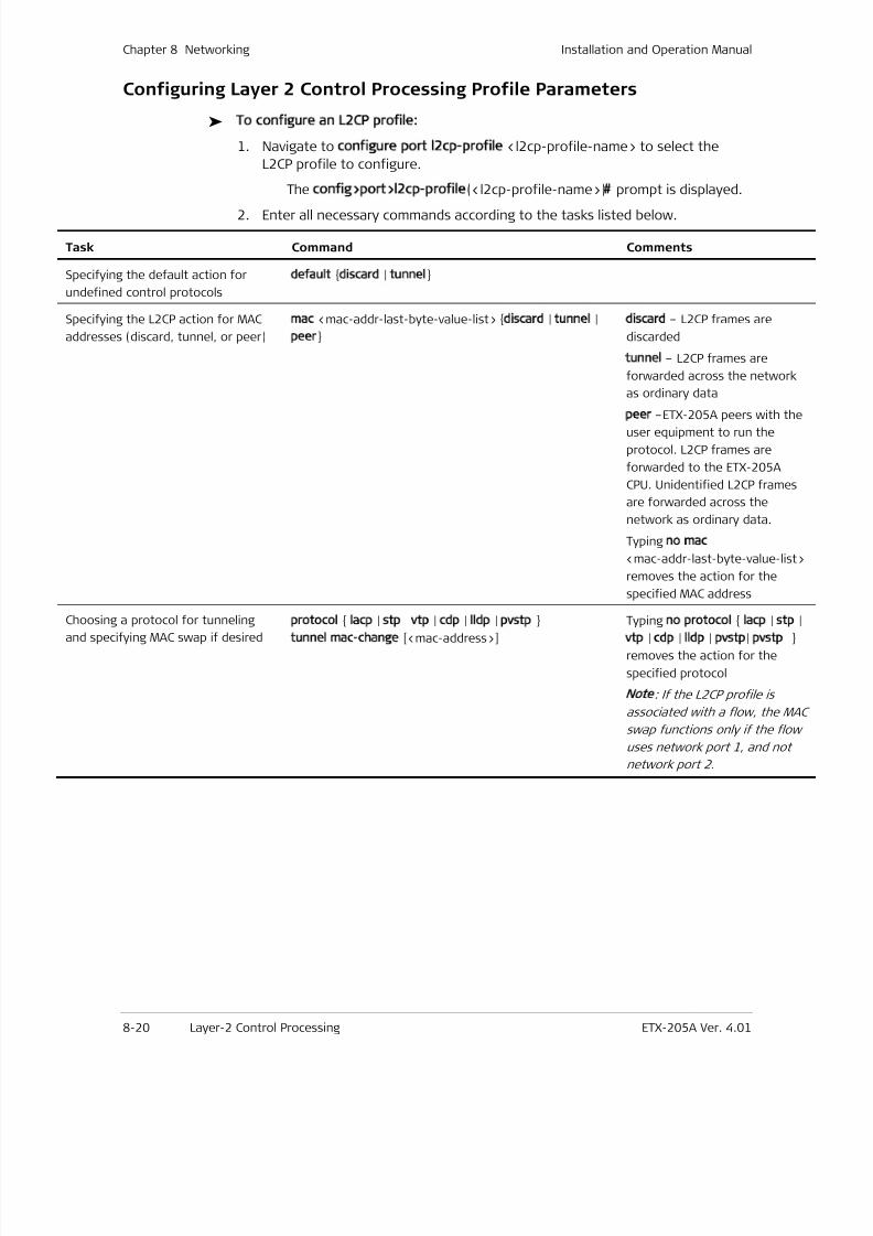
7/25/2019 Manual ETX-205A
http://slidepdf.com/reader/full/manual-etx-205a 206/409

7/25/2019 Manual ETX-205A
http://slidepdf.com/reader/full/manual-etx-205a 207/409
Installation and Operation Manual Chapter 8 Networking
ETX-205A Ver. 4.01 Layer-2 Control Processing 8-21
Example
To add L2CP profile named layer2ctrl1 with discard action for hex byte 0x01 and
0x03:
ETX-205A# configure port
ETX-205A>config>port# l2cp-profile layer2ctrl1
ETX-205A>config>port>l2cp-profile(layer2ctrl1)$ mac 0x01 discard
ETX-205A>config>port>l2cp-profile(layer2ctrl1)$ mac 0x03 discard
ETX-205A>config>port>l2cp-profile(layer2ctrl1)$ info detail
mac 0x00 tunnel
mac 0x01 discard
mac 0x02 tunnel
mac 0x03 discard
mac 0x04 tunnel
mac 0x05 tunnel
mac 0x06 tunnel
mac 0x07 tunnel
mac 0x08 tunnel
mac 0x09 tunnel
mac 0x0a tunnel mac 0x0b tunnel
mac 0x0c tunnel
mac 0x0d tunnel
mac 0x0e tunnel
mac 0x0f tunnel
mac 0x10 tunnel
mac 0x20 tunnel
mac 0x21 tunnel
mac 0x22 tunnel
mac 0x23 tunnel
mac 0x24 tunnel
mac 0x25 tunnel
mac 0x26 tunnel
mac 0x27 tunnel
mac 0x28 tunnel
mac 0x29 tunnel
mac 0x2a tunnel
mac 0x2b tunnel
mac 0x2c tunnel
mac 0x2d tunnel
mac 0x2e tunnel
mac 0x2f tunnel
default tunnel
ETX-205A>config>port>l2cp-profile(layer2ctrl1)$
To delete L2CP profile named layer2ctrl1:
ETX-205A# configure port
ETX-205A>config>port# no l2cp-profile layer2ctrl1
ETX-205A>config>port#

7/25/2019 Manual ETX-205A
http://slidepdf.com/reader/full/manual-etx-205a 208/409
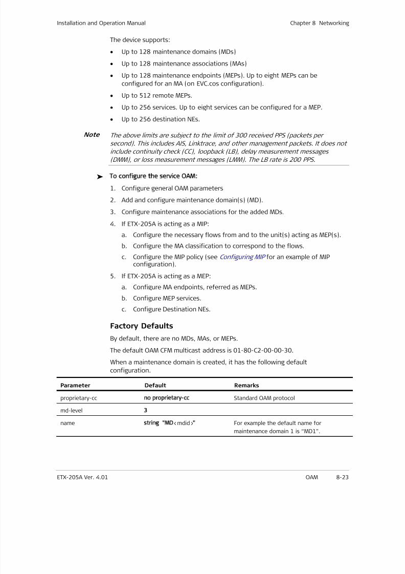
7/25/2019 Manual ETX-205A
http://slidepdf.com/reader/full/manual-etx-205a 209/409
Installation and Operation Manual Chapter 8 Networking
ETX-205A Ver. 4.01 OAM 8-23
The device supports:
• Up to 128 maintenance domains (MDs)
• Up to 128 maintenance associations (MAs)
• Up to 128 maintenance endpoints (MEPs). Up to eight MEPs can be
configured for an MA (on EVC.cos configuration).
• Up to 512 remote MEPs.
• Up to 256 services. Up to eight services can be configured for a MEP.
• Up to 256 destination NEs.
The above limits are subject to the limit of 300 received PPS (packets per
second). This includes AIS, Linktrace, and other management packets. It does not
include continuity check (CC), loopback (LB), delay measurement messages
(DMM), or loss measurement messages (LMM). The LB rate is 200 PPS.
To configure the service OAM:
1. Configure general OAM parameters2. Add and configure maintenance domain(s) (MD).
3. Configure maintenance associations for the added MDs.
4. If ETX-205A is acting as a MIP:
a. Configure the necessary flows from and to the unit(s) acting as MEP(s).
b. Configure the MA classification to correspond to the flows.
c. Configure the MIP policy (see Configuring MIP for an example of MIPconfiguration).
5. If ETX-205A is acting as a MEP:
a. Configure MA endpoints, referred as MEPs.
b. Configure MEP services.
c. Configure Destination NEs.
Factory Defaults
By default, there are no MDs, MAs, or MEPs.
The default OAM CFM multicast address is 01-80-C2-00-00-30.
When a maintenance domain is created, it has the following default
configuration.
Parameter Default Remarks
proprietary-cc no proprietary-cc Standard OAM protocol
md-level 3
name string MD<mdid> For example the default name for
maintenance domain 1 is “MD1”.
Note
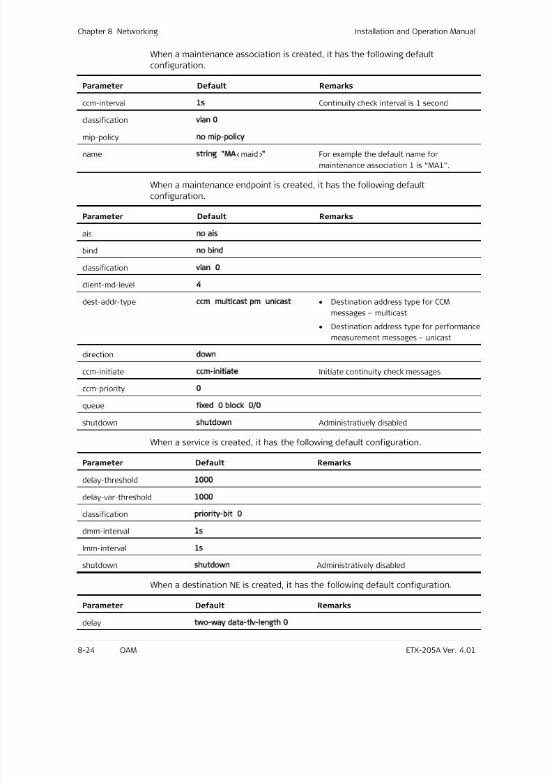
7/25/2019 Manual ETX-205A
http://slidepdf.com/reader/full/manual-etx-205a 210/409
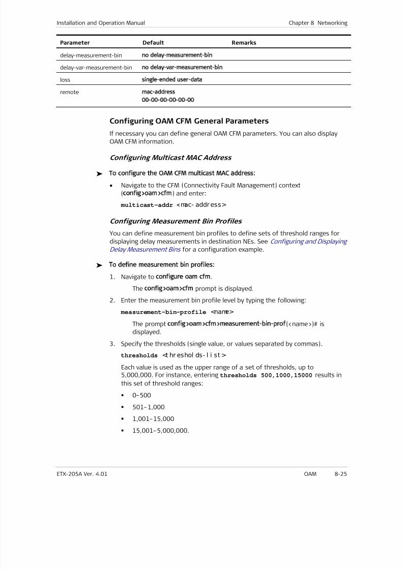
7/25/2019 Manual ETX-205A
http://slidepdf.com/reader/full/manual-etx-205a 211/409
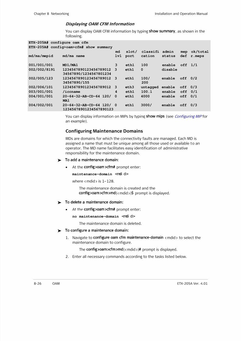
7/25/2019 Manual ETX-205A
http://slidepdf.com/reader/full/manual-etx-205a 212/409
Chapter 8 Networking Installation and Operation Manual
8-26 OAM ETX-205A Ver. 4.01
Displaying OAM CFM Information
You can display OAM CFM information by typing show summary, as shown in the
following.
ETX-205A# configure oam cfm
ETX-205A# config>oam>cfm# show summary
md slot/ classifi admin mep ok/total
md/ma/mepid md/ma name lvl port cation status def r.meps
001/001/001 MD1/MA1 3 eth1 100 enable off 1/1
002/002/8191 1234567890123456789012 3 eth1 0 disable34567890/1234567801234
002/005/123 1234567890123456789012 3 eth1 100/ enable off 0/234567890/155 200
002/006/101 1234567890123456789012 3 eth3 untagged enable off 0/3
003/001/001 /iccname 4 eth1 100.1 enable off 0/1
004/001/001 20-64-32-AB-CD-64 120/ 0 eth1 4000 enable off 0/1
MA1
004/002/001 20-64-32-AB-CD-64 120/ 0 eth1 3000/ enable off 0/312345678901234567890123
You can display information on MIPs by typing show mips (see Configuring MIP for
an example).
Configuring Maintenance Domains
MDs are domains for which the connectivity faults are managed. Each MD is
assigned a name that must be unique among all those used or available to an
operator. The MD name facilitates easy identification of administrative
responsibility for the maintenance domain.
To add a maintenance domain:
• At the config>oam>cfm# prompt enter:
maintenance-domain <mdi d>
where <mdid> is 1–128.
The maintenance domain is created and the
config>oam>cfm>md(<mdid>)$ prompt is displayed.
To delete a maintenance domain:
• At the config>oam>cfm# prompt enter:
no maintenance-domain <mdi d>
The maintenance domain is deleted.
To configure a maintenance domain:
1. Navigate to configure oam cfm maintenance-domain <mdid> to select the
maintenance domain to configure.
The config>oam>cfm>md(<mdid>)# prompt is displayed.
2. Enter all necessary commands according to the tasks listed below.
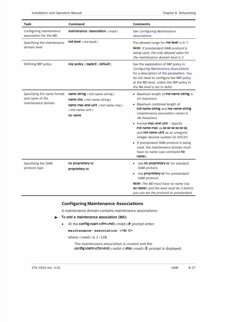
7/25/2019 Manual ETX-205A
http://slidepdf.com/reader/full/manual-etx-205a 213/409
Installation and Operation Manual Chapter 8 Networking
ETX-205A Ver. 4.01 OAM 8-27
Task Command Comments
Configuring maintenance
association for the MD
maintenance -association <maid> See Configuring Maintenance
Associations
Specifying the maintenance
domain level
md-level <md-level> The allowed range for md-level is 0–7
Note
: If prestandard OAM protocol is
being used, the only allowed value forthe maintenance domain level is 3.
Defining MIP policymip-policy explicit | default See the explanation of MIP policy in
Configuring Maintenance Associations
for a description of the parameters. You
do not need to configure the MIP policy
at the MD level, unless the MIP policy in
the MA level is set to defer
Specifying the name format
and name of the
maintenance domain
name string <md-name-string>
name dns <md-name-string>
name mac-and-uint <md-name-mac>
<md-name-uint>
no name
• Maximum length of md-name-string is
43 characters
• Maximum combined length of
md-name-string and ma-name-string
(maintenance association name) is
48 characters
• Format mac-and-uint – Specify
md-name-mac as xx-xx-xx-xx-xx-xx,
and md-name-uint as an unsigned
integer decimal number (0–65535)
• If prestandard OAM protocol is being
used, the maintenance domain must
have no name (use command no
name).
Specifying the OAM
protocol type
no proprietary-cc
proprietary-cc
• Use no proprietary-cc for standard
OAM protocol
• Use proprietary-cc for prestandard
OAM protocol.
Note: The MD must have no name (via
no name
) and the level must be 3 before
you can set the protocol to prestandard.
Configuring Maintenance Associations
A maintenance domain contains maintenance associations.
To add a maintenance association (MA):
• At the config>oam>cfm>md(<mdid>)# prompt enter:
maintenance- association <mai d>
where <maid> is 1–128.
The maintenance association is created and the
config>oam>cfm>md(<mdid>)>ma(<maid>)$ prompt is displayed.
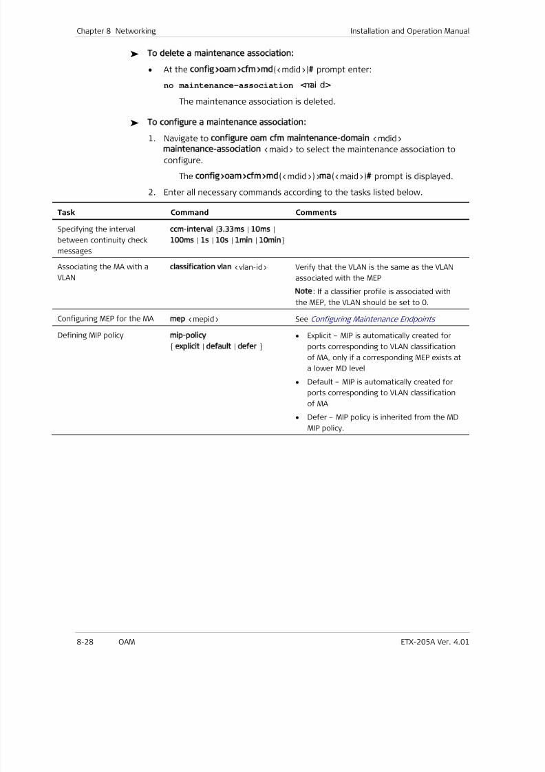
7/25/2019 Manual ETX-205A
http://slidepdf.com/reader/full/manual-etx-205a 214/409
Chapter 8 Networking Installation and Operation Manual
8-28 OAM ETX-205A Ver. 4.01
To delete a maintenance association:
• At the config>oam>cfm>md(<mdid>)# prompt enter:
no maintenance-association <mai d>
The maintenance association is deleted.
To configure a maintenance association:
1. Navigate to configure oam cfm maintenance-domain <mdid>
maintenance-association <maid> to select the maintenance association to
configure.
The config>oam>cfm>md(<mdid>)>ma(<maid>)# prompt is displayed.
2. Enter all necessary commands according to the tasks listed below.
Task Command Comments
Specifying the interval
between continuity check
messages
ccm-interval 3.33ms | 10ms |
100ms | 1s | 10s | 1min | 10min
Associating the MA with a
VLAN
classification vlan <vlan-id> Verify that the VLAN is the same as the VLAN
associated with the MEP
Note: If a classifier profile is associated with
the MEP, the VLAN should be set to 0.
Configuring MEP for the MAmep <mepid> See Configuring Maintenance Endpoints
Defining MIP policymip-policy
explicit | default | defer
• Explicit – MIP is automatically created for
ports corresponding to VLAN classification
of MA, only if a corresponding MEP exists at
a lower MD level
•
Default – MIP is automatically created forports corresponding to VLAN classification
of MA
• Defer – MIP policy is inherited from the MD
MIP policy.
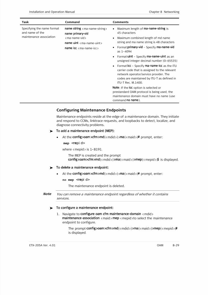
7/25/2019 Manual ETX-205A
http://slidepdf.com/reader/full/manual-etx-205a 215/409
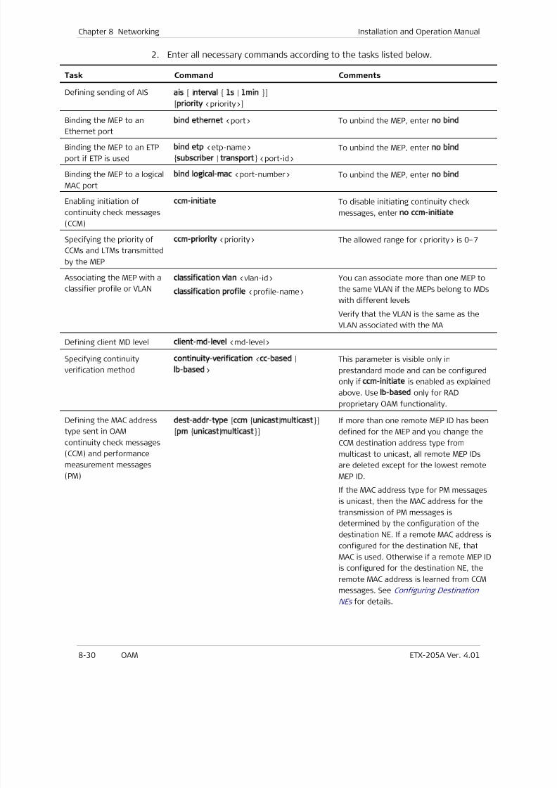
7/25/2019 Manual ETX-205A
http://slidepdf.com/reader/full/manual-etx-205a 216/409
Chapter 8 Networking Installation and Operation Manual
8-30 OAM ETX-205A Ver. 4.01
2. Enter all necessary commands according to the tasks listed below.
Task Command Comments
Defining sending of AISais [ interval 1s | 1min ]
[priority <priority>]
Binding the MEP to an
Ethernet port
bind ethernet <port> To unbind the MEP, enter no bind
Binding the MEP to an ETP
port if ETP is used
bind etp <etp-name>
subscriber | transport <port-id>
To unbind the MEP, enter no bind
Binding the MEP to a logical
MAC port
bind logical-mac <port-number> To unbind the MEP, enter no bind
Enabling initiation of
continuity check messages
(CCM)
ccm-initiate To disable initiating continuity check
messages, enter no ccm-initiate
Specifying the priority of
CCMs and LTMs transmitted
by the MEP
ccm-priority <priority> The allowed range for <priority> is 0–7
Associating the MEP with a
classifier profile or VLAN
classification vlan <vlan-id>
classification profile <profile-name>
You can associate more than one MEP to
the same VLAN if the MEPs belong to MDs
with different levels
Verify that the VLAN is the same as the
VLAN associated with the MA
Defining client MD level client-md-level <md-level>
Specifying continuity
verification method
continuity-verification <cc-based |
lb-based>
This parameter is visible only in
prestandard mode and can be configured
only if ccm-initiate is enabled as explained
above. Use lb-based only for RADproprietary OAM functionality.
Defining the MAC address
type sent in OAM
continuity check messages
(CCM) and performance
measurement messages
(PM)
dest-addr-type [ccm unicast|multicast]
[pm unicast|multicast]
If more than one remote MEP ID has been
defined for the MEP and you change the
CCM destination address type from
multicast to unicast, all remote MEP IDs
are deleted except for the lowest remote
MEP ID.
If the MAC address type for PM messages
is unicast, then the MAC address for the
transmission of PM messages is
determined by the configuration of thedestination NE. If a remote MAC address is
configured for the destination NE, that
MAC is used. Otherwise if a remote MEP ID
is configured for the destination NE, the
remote MAC address is learned from CCM
messages. See Configuring Destination
NEs for details.
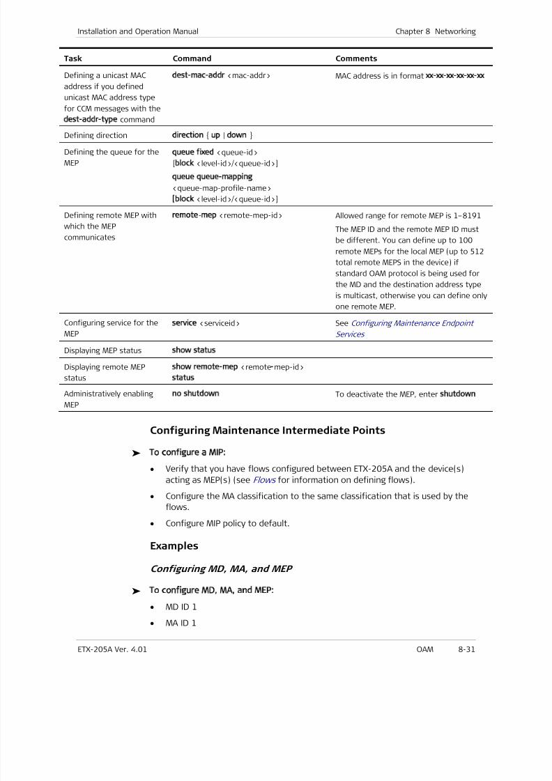
7/25/2019 Manual ETX-205A
http://slidepdf.com/reader/full/manual-etx-205a 217/409
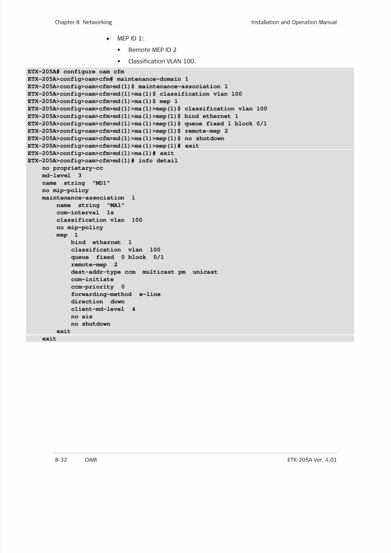
7/25/2019 Manual ETX-205A
http://slidepdf.com/reader/full/manual-etx-205a 218/409
Chapter 8 Networking Installation and Operation Manual
8-32 OAM ETX-205A Ver. 4.01
• MEP ID 1:
Remote MEP ID 2
Classification VLAN 100.
ETX-205A# configure oam cfm
ETX-205A>config>oam>cfm# maintenance-domain 1
ETX-205A>config>oam>cfm>md(1)$ maintenance-association 1
ETX-205A>config>oam>cfm>md(1)>ma(1)$ classification vlan 100
ETX-205A>config>oam>cfm>md(1)>ma(1)$ mep 1
ETX-205A>config>oam>cfm>md(1)>ma(1)>mep(1)$ classification vlan 100
ETX-205A>config>oam>cfm>md(1)>ma(1)>mep(1)$ bind ethernet 1
ETX-205A>config>oam>cfm>md(1)>ma(1)>mep(1)$ queue fixed 1 block 0/1
ETX-205A>config>oam>cfm>md(1)>ma(1)>mep(1)$ remote-mep 2
ETX-205A>config>oam>cfm>md(1)>ma(1)>mep(1)$ no shutdown
ETX-205A>config>oam>cfm>md(1)>ma(1)>mep(1)# exit
ETX-205A>config>oam>cfm>md(1)>ma(1)# exit
ETX-205A>config>oam>cfm>md(1)# info detail
no proprietary-cc
md-level 3
name string "MD1"no mip-policy
maintenance-association 1
name string "MA1"
ccm-interval 1s
classification vlan 100
no mip-policy
mep 1
bind ethernet 1
classification vlan 100
queue fixed 0 block 0/1
remote-mep 2
dest-addr-type ccm multicast pm unicast
ccm-initiate
ccm-priority 0
forwarding-method e-line
direction down
client-md-level 4
no ais
no shutdown
exit
exit
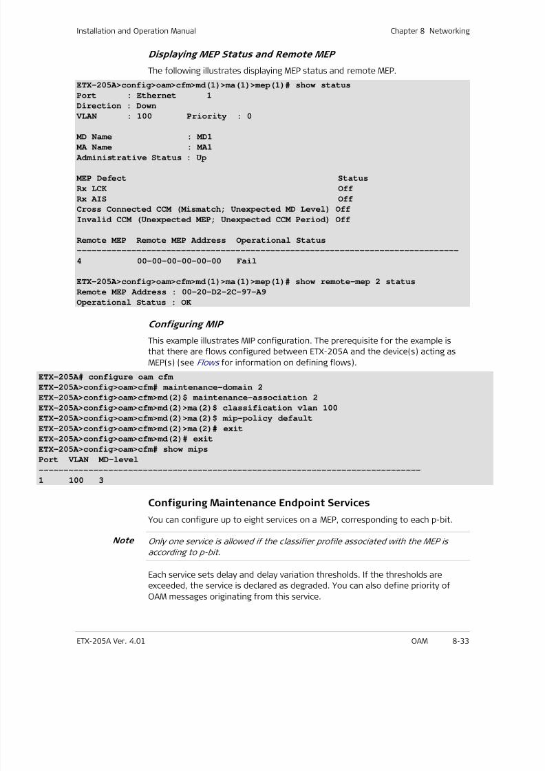
7/25/2019 Manual ETX-205A
http://slidepdf.com/reader/full/manual-etx-205a 219/409
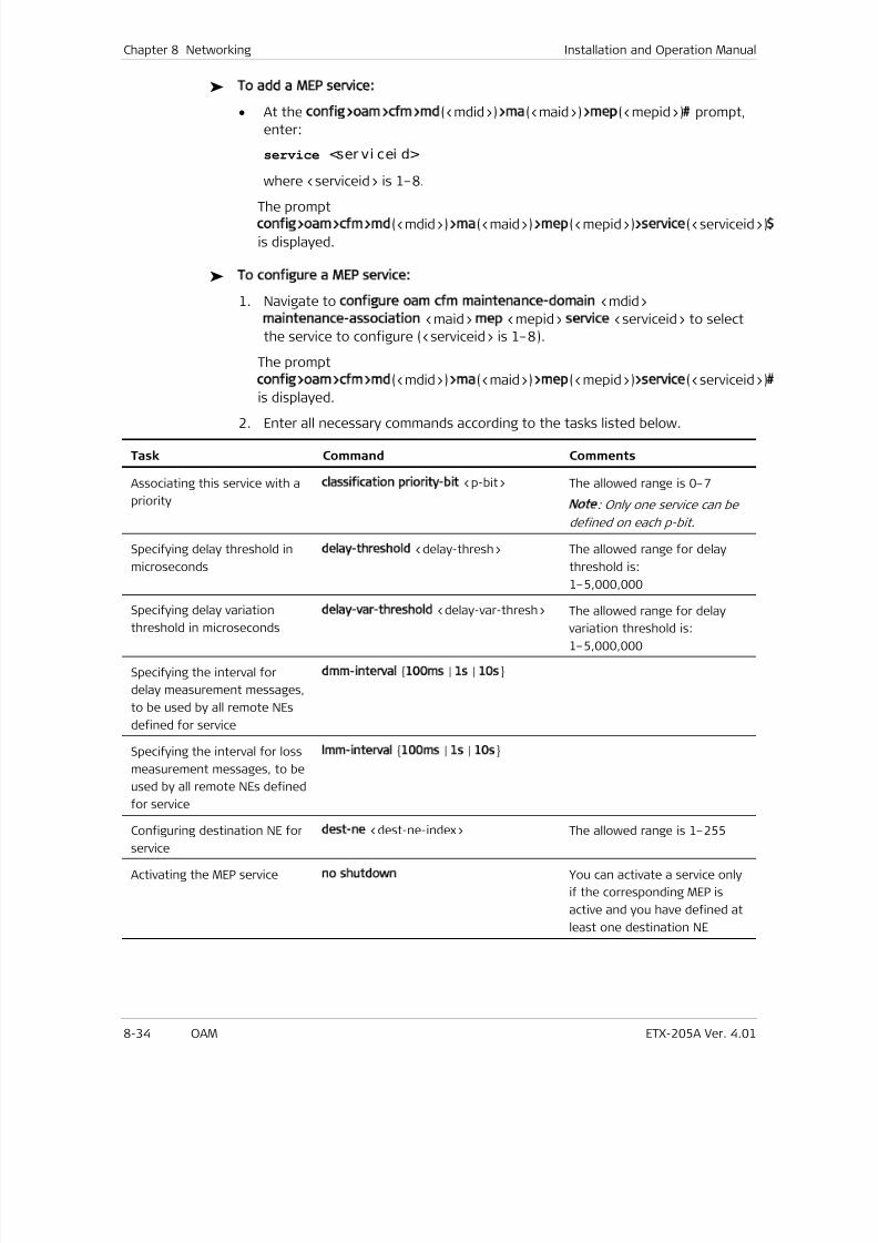
7/25/2019 Manual ETX-205A
http://slidepdf.com/reader/full/manual-etx-205a 220/409
Chapter 8 Networking Installation and Operation Manual
8-34 OAM ETX-205A Ver. 4.01
To add a MEP service:
• At the config>oam>cfm>md(<mdid>)>ma(<maid>)>mep(<mepid>)# prompt,
enter:
service <ser vi cei d>
where <serviceid> is 1–8.
The promptconfig>oam>cfm>md(<mdid>)>ma(<maid>)>mep(<mepid>)>service(<serviceid>)$
is displayed.
To configure a MEP service:
1. Navigate to configure oam cfm maintenance-domain <mdid>
maintenance-association <maid> mep <mepid> service <serviceid> to select
the service to configure (<serviceid> is 1–8).
The prompt
config>oam>cfm>md(<mdid>)>ma(<maid>)>mep(<mepid>)>service(<serviceid>)#
is displayed.
2. Enter all necessary commands according to the tasks listed below.
Task Command Comments
Associating this service with a
priority
classification priority-bit <p-bit> The allowed range is 0–7
Note
: Only one service can be
defined on each p-bit.
Specifying delay threshold in
microseconds
delay-threshold <delay-thresh> The allowed range for delay
threshold is:
1–5,000,000
Specifying delay variation
threshold in microseconds
delay-var-threshold <delay-var-thresh> The allowed range for delay
variation threshold is:
1–5,000,000
Specifying the interval for
delay measurement messages,
to be used by all remote NEs
defined for service
dmm-interval 100ms | 1s | 10s
Specifying the interval for loss
measurement messages, to be
used by all remote NEs defined
for service
lmm-interval 100ms | 1s | 10s
Configuring destination NE for
service
dest-ne <dest-ne-index> The allowed range is 1–255
Activating the MEP service no shutdown You can activate a service only
if the corresponding MEP is
active and you have defined at
least one destination NE
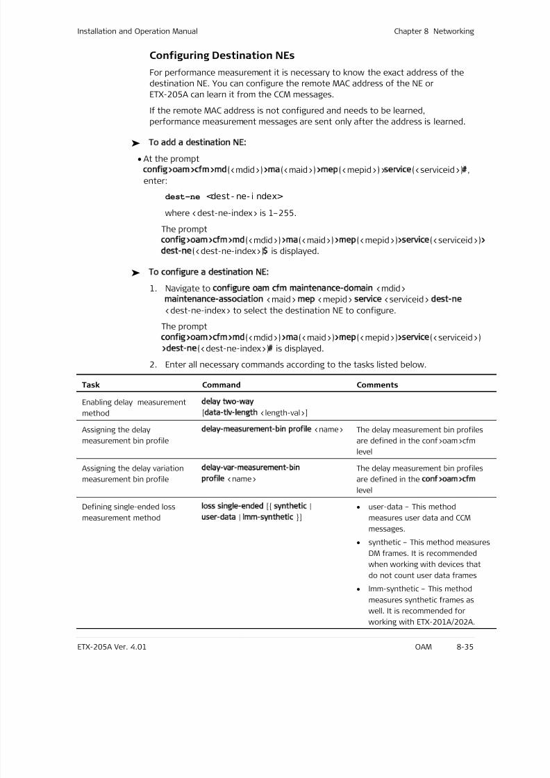
7/25/2019 Manual ETX-205A
http://slidepdf.com/reader/full/manual-etx-205a 221/409
Installation and Operation Manual Chapter 8 Networking
ETX-205A Ver. 4.01 OAM 8-35
Configuring Destination NEs
For performance measurement it is necessary to know the exact address of the
destination NE. You can configure the remote MAC address of the NE or
ETX-205A can learn it from the CCM messages.
If the remote MAC address is not configured and needs to be learned,
performance measurement messages are sent only after the address is learned.
To add a destination NE:
• At the prompt
config>oam>cfm>md(<mdid>)>ma(<maid>)>mep(<mepid>)>service(<serviceid>)#,
enter:
dest-ne <dest - ne- i ndex>
where <dest-ne-index> is 1–255.
The prompt
config>oam>cfm>md(<mdid>)>ma(<maid>)>mep(<mepid>)>service(<serviceid>)>
dest-ne(<dest-ne-index>)$ is displayed.
To configure a destination NE:
1. Navigate to configure oam cfm maintenance-domain <mdid>
maintenance-association <maid> mep <mepid> service <serviceid> dest-ne
<dest-ne-index> to select the destination NE to configure.
The prompt
config>oam>cfm>md(<mdid>)>ma(<maid>)>mep(<mepid>)>service(<serviceid>)
>dest-ne(<dest-ne-index>)# is displayed.
2. Enter all necessary commands according to the tasks listed below.
Task Command Comments
Enabling delay measurement
method
delay two-way
[data-tlv-length <length-val>]
Assigning the delay
measurement bin profile
delay-measurement-bin profile <name> The delay measurement bin profiles
are defined in the conf>oam>cfm
level
Assigning the delay variation
measurement bin profile
delay-var-measurement-bin
profile <name>
The delay measurement bin profiles
are defined in the conf>oam>cfm
level
Defining single-ended loss
measurement method
loss single-ended [ synthetic |
user-data | lmm-synthetic ]
• user-data – This method
measures user data and CCMmessages.
• synthetic – This method measures
DM frames. It is recommended
when working with devices that
do not count user data frames
• lmm-synthetic – This method
measures synthetic frames as
well. It is recommended for
working with ETX-201A/202A.
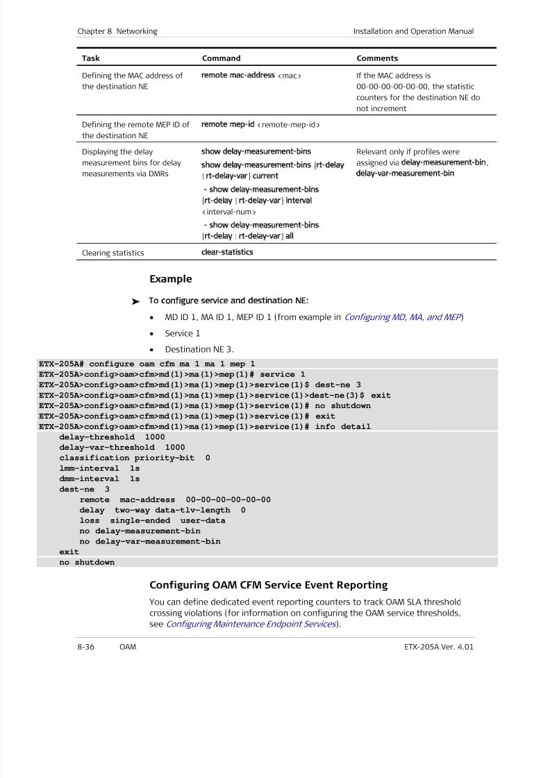
7/25/2019 Manual ETX-205A
http://slidepdf.com/reader/full/manual-etx-205a 222/409
Chapter 8 Networking Installation and Operation Manual
8-36 OAM ETX-205A Ver. 4.01
Task Command Comments
Defining the MAC address of
the destination NE
remote mac-address <mac> If the MAC address is
00-00-00-00-00-00, the statistic
counters for the destination NE do
not increment
Defining the remote MEP ID of
the destination NE
remote mep-id <remote-mep-id>
Displaying the delay
measurement bins for delay
measurements via DMRs
show delay-measurement-bins
show delay-measurement-bins rt-delay
| rt-delay-var current
- show delay-measurement-bins
rt-delay | rt-delay-var interval
<interval-num>
- show delay-measurement-bins
rt-delay | rt-delay-var all
Relevant only if profiles were
assigned via delay-measurement-bin,
delay-var-measurement-bin
Clearing statistics clear-statistics
Example
To configure service and destination NE:
• MD ID 1, MA ID 1, MEP ID 1 (from example in Configuring MD, MA, and MEP )
• Service 1
• Destination NE 3.
ETX-205A# configure oam cfm ma 1 ma 1 mep 1
ETX-205A>config>oam>cfm>md(1)>ma(1)>mep(1)# service 1
ETX-205A>config>oam>cfm>md(1)>ma(1)>mep(1)>service(1)$ dest-ne 3ETX-205A>config>oam>cfm>md(1)>ma(1)>mep(1)>service(1)>dest-ne(3)$ exit
ETX-205A>config>oam>cfm>md(1)>ma(1)>mep(1)>service(1)# no shutdown
ETX-205A>config>oam>cfm>md(1)>ma(1)>mep(1)>service(1)# exit
ETX-205A>config>oam>cfm>md(1)>ma(1)>mep(1)>service(1)# info detail
delay-threshold 1000
delay-var-threshold 1000
classification priority-bit 0
lmm-interval 1s
dmm-interval 1s
dest-ne 3
remote mac-address 00-00-00-00-00-00
delay two-way data-tlv-length 0
loss single-ended user-data
no delay-measurement-bin
no delay-var-measurement-bin
exit
no shutdown
Configuring OAM CFM Service Event Reporting
You can define dedicated event reporting counters to track OAM SLA threshold
crossing violations (for information on configuring the OAM service thresholds,
see Configuring Maintenance Endpoint Services ).
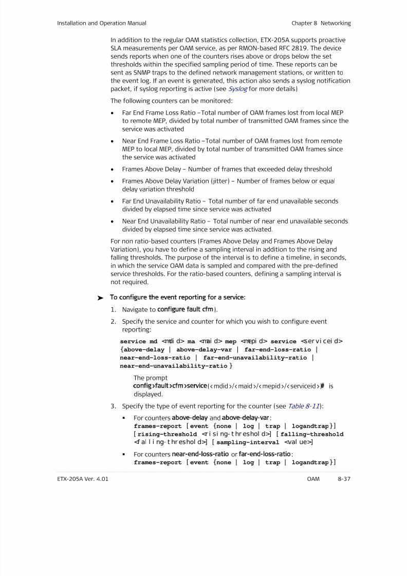
7/25/2019 Manual ETX-205A
http://slidepdf.com/reader/full/manual-etx-205a 223/409
Installation and Operation Manual Chapter 8 Networking
ETX-205A Ver. 4.01 OAM 8-37
In addition to the regular OAM statistics collection, ETX-205A supports proactive
SLA measurements per OAM service, as per RMON-based RFC 2819. The device
sends reports when one of the counters rises above or drops below the set
thresholds within the specified sampling period of time. These reports can be
sent as SNMP traps to the defined network management stations, or written to
the event log. If an event is generated, this action also sends a syslog notification
packet, if syslog reporting is active (see Syslog for more details)
The following counters can be monitored:
• Far End Frame Loss Ratio –Total number of OAM frames lost from local MEP
to remote MEP, divided by total number of transmitted OAM frames since the
service was activated
• Near End Frame Loss Ratio –Total number of OAM frames lost from remote
MEP to local MEP, divided by total number of transmitted OAM frames since
the service was activated
• Frames Above Delay – Number of frames that exceeded delay threshold
• Frames Above Delay Variation (jitter) – Number of frames below or equal
delay variation threshold• Far End Unavailability Ratio – Total number of far end unavailable seconds
divided by elapsed time since service was activated
• Near End Unavailability Ratio – Total number of near end unavailable seconds
divided by elapsed time since service was activated.
For non ratio-based counters (Frames Above Delay and Frames Above Delay
Variation), you have to define a sampling interval in addition to the rising and
falling thresholds. The purpose of the interval is to define a timeline, in seconds,
in which the service OAM data is sampled and compared with the pre-defined
service thresholds. For the ratio-based counters, defining a sampling interval is
not required.
To configure the event reporting for a service:
1. Navigate to configure fault cfm).
2. Specify the service and counter for which you wish to configure event
reporting:
service md <mdi d> ma <mai d> mep <mepi d> service <ser vi cei d>
above-delay | above-delay-var | far-end-loss-ratio |
near-end-loss-ratio | far-end-unavailability-ratio |
near-end-unavailability-ratio
The prompt
config>fault>cfm>service(<mdid>/<maid>/<mepid>/<serviceid>)# is
displayed.
3. Specify the type of event reporting for the counter (see Table 8-11):
For counters above-delay and above-delay-var:frames-report [ event none | log | trap | logandtrap]
[ rising-threshold <r i si ng- t hr eshol d>] [ falling-threshold
<f al l i ng- t hr eshol d>] [ sampling-interval <val ue>]
For counters near-end-loss-ratio or far-end-loss-ratio:frames-report [ event none | log | trap | logandtrap]
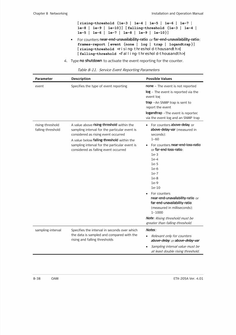
7/25/2019 Manual ETX-205A
http://slidepdf.com/reader/full/manual-etx-205a 224/409
Chapter 8 Networking Installation and Operation Manual
8-38 OAM ETX-205A Ver. 4.01
[ rising-threshold 1e-3 | 1e-4 | 1e-5 | 1e-6 | 1e-7 |
1e-8 | 1e-9 | 1e-10] [ falling-threshold 1e-3 | 1e-4 |
1e-5 | 1e-6 | 1e-7 | 1e-8 | 1e-9 | 1e-10]
For counters near-end-unavailability-ratio or far-end-unavailability-ratio:frames-report [ event none | log | trap | logandtrap]
[ rising-threshold <r i si ng- t hr eshol d-t housandt h>]
[falling-threshold
<f al l i ng- t hr eshol d-t housandth>]
4. Type no shutdown to activate the event reporting for the counter.
Table 8-11. Service Event Reporting Parameters
Parameter Description Possible Values
event Specifies the type of event reporting none – The event is not reported
log – The event is reported via the
event log
trap –An SNMP trap is sent to
report the event
logandtrap –The event is reported
via the event log and an SNMP trap
rising-threshold
falling-threshold
A value above rising-threshold within the
sampling interval for the particular event is
considered as rising event occurred
A value below falling-threshold within the
sampling interval for the particular event is
considered as falling event occurred
• For counters above-delay or
above-delay-var (measured in
seconds):
1–60
• For counters near-end-loss-ratio
or far-end-loss-ratio:
1e-3
1e-4
1e-5
1e-6
1e-7
1e-8
1e-9
1e-10
• For counters
near-end-unavailability-ratio or
far-end-unavailability-ratio
(measured in milliseconds):
1–1000
Note: Rising threshold must be
greater than falling-threshold.
sampling-interval Specifies the interval in seconds over which
the data is sampled and compared with the
rising and falling thresholds
Notes:
• Relevant only for counters
above delay or above delay var
• Sampling interval value must be
at least double rising threshold.
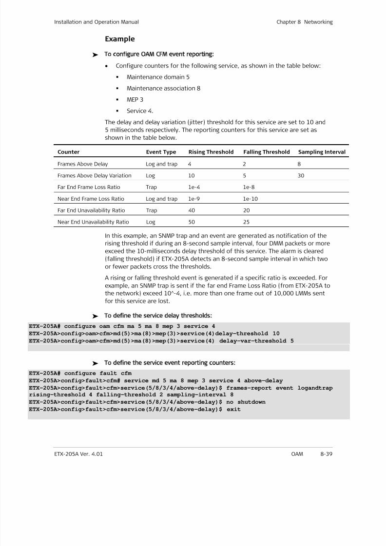
7/25/2019 Manual ETX-205A
http://slidepdf.com/reader/full/manual-etx-205a 225/409
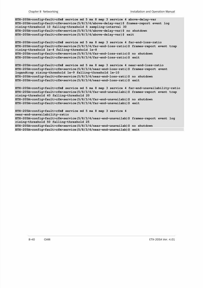
7/25/2019 Manual ETX-205A
http://slidepdf.com/reader/full/manual-etx-205a 226/409
Chapter 8 Networking Installation and Operation Manual
8-40 OAM ETX-205A Ver. 4.01
ETX-205A>config>fault>cfm# service md 5 ma 8 mep 3 service 4 above-delay-var
ETX-205A>config>fault>cfm>service(5/8/3/4/above-delay-var)$ frames-report event log
rising-threshold 10 falling-threshold 5 sampling-interval 30
ETX-205A>config>fault>cfm>service(5/8/3/4/above-delay-var)$ no shutdown
ETX-205A>config>fault>cfm>service(5/8/3/4/above-delay-var)$ exit
ETX-205A>config>fault>cfm# service md 5 ma 8 mep 3 service 4 far-end-loss-ratio
ETX-205A>config>fault>cfm>service(5/8/3/4/far-end-loss-ratio)$ frames-report event trap
rising-threshold 1e-4 falling-threshold 1e-8
ETX-205A>config>fault>cfm>service(5/8/3/4/far-end-loss-ratio)$ no shutdown
ETX-205A>config>fault>cfm>service(5/8/3/4/far-end-loss-ratio)$ exit
ETX-205A>config>fault>cfm# service md 5 ma 8 mep 3 service 4 near-end-loss-ratio
ETX-205A>config>fault>cfm>service(5/8/3/4/near-end-loss-rati)$ frames-report event
logandtrap rising-threshold 1e-9 falling-threshold 1e-10
ETX-205A>config>fault>cfm>service(5/8/3/4/near-end-loss-rati)$ no shutdown
ETX-205A>config>fault>cfm>service(5/8/3/4/near-end-loss-rati)$ exit
ETX-205A>config>fault>cfm# service md 5 ma 8 mep 3 service 4 far-end-unavailability-ratio
ETX-205A>config>fault>cfm>service(5/8/3/4/far-end-unavailabi)$ frames-report event trap
rising-threshold 40 falling-threshold 20ETX-205A>config>fault>cfm>service(5/8/3/4/far-end-unavailabi)$ no shutdown
ETX-205A>config>fault>cfm>service(5/8/3/4/far-end-unavailabi)$ exit
ETX-205A>config>fault>cfm# service md 5 ma 8 mep 3 service 4
near-end-unavailability-ratio
ETX-205A>config>fault>cfm>service(5/8/3/4/near-end-unavailab)$ frames-report event logrising-threshold 50 falling-threshold 25
ETX-205A>config>fault>cfm>service(5/8/3/4/near-end-unavailab)$ no shutdown
ETX-205A>config>fault>cfm>service(5/8/3/4/near-end-unavailab)$ exit
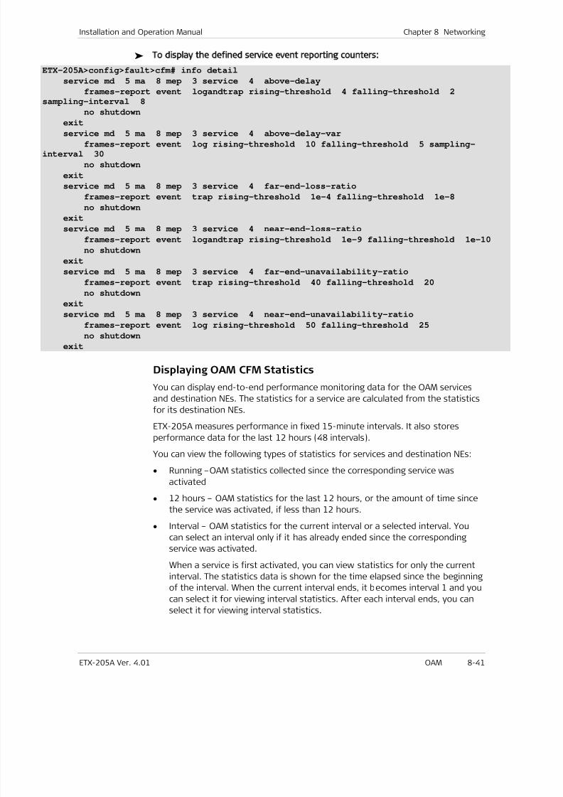
7/25/2019 Manual ETX-205A
http://slidepdf.com/reader/full/manual-etx-205a 227/409
Installation and Operation Manual Chapter 8 Networking
ETX-205A Ver. 4.01 OAM 8-41
To display the defined service event reporting counters:
ETX-205A>config>fault>cfm# info detail
service md 5 ma 8 mep 3 service 4 above-delay
frames-report event logandtrap rising-threshold 4 falling-threshold 2
sampling-interval 8
no shutdown
exit
service md 5 ma 8 mep 3 service 4 above-delay-varframes-report event log rising-threshold 10 falling-threshold 5 sampling-
interval 30
no shutdown
exit
service md 5 ma 8 mep 3 service 4 far-end-loss-ratio
frames-report event trap rising-threshold 1e-4 falling-threshold 1e-8
no shutdown
exit
service md 5 ma 8 mep 3 service 4 near-end-loss-ratio
frames-report event logandtrap rising-threshold 1e-9 falling-threshold 1e-10
no shutdown
exitservice md 5 ma 8 mep 3 service 4 far-end-unavailability-ratio
frames-report event trap rising-threshold 40 falling-threshold 20
no shutdown
exit
service md 5 ma 8 mep 3 service 4 near-end-unavailability-ratio
frames-report event log rising-threshold 50 falling-threshold 25
no shutdown
exit
Displaying OAM CFM Statistics
You can display end-to-end performance monitoring data for the OAM services
and destination NEs. The statistics for a service are calculated from the statisticsfor its destination NEs.
ETX-205A measures performance in fixed 15-minute intervals. It also stores
performance data for the last 12 hours (48 intervals).
You can view the following types of statistics for services and destination NEs:
• Running –OAM statistics collected since the corresponding service was
activated
• 12 hours – OAM statistics for the last 12 hours, or the amount of time since
the service was activated, if less than 12 hours.
•
Interval – OAM statistics for the current interval or a selected interval. Youcan select an interval only if it has already ended since the corresponding
service was activated.
When a service is first activated, you can view statistics for only the current
interval. The statistics data is shown for the time elapsed since the beginning
of the interval. When the current interval ends, it becomes interval 1 and you
can select it for viewing interval statistics. After each interval ends, you can
select it for viewing interval statistics.
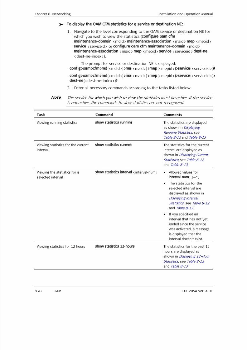
7/25/2019 Manual ETX-205A
http://slidepdf.com/reader/full/manual-etx-205a 228/409
Chapter 8 Networking Installation and Operation Manual
8-42 OAM ETX-205A Ver. 4.01
To display the OAM CFM statistics for a service or destination NE:
1. Navigate to the level corresponding to the OAM service or destination NE for
which you wish to view the statistics (configure oam cfm
maintenance-domain <mdid> maintenance-association <maid> mep <mepid>
service <serviceid> or configure oam cfm maintenance-domain <mdid>
maintenance-association <maid> mep <mepid> service <serviceid> dest-ne
<dest-ne-index>).The prompt for service or destination NE is displayed:
config>oam>cfm>md(<mdid>)>ma(<maid>)>mep(<mepid>)>service(<serviceid>)#
config>oam>cfm>md(<mdid>)>ma(<maid>)>mep(<mepid>)>service(<serviceid>)>
dest-ne(<dest-ne-index>)#
2. Enter all necessary commands according to the tasks listed below.
The service for which you wish to view the statistics must be active. If the service
is not active, the commands to view statistics are not recognized.
Task Command Comments
Viewing running statistics show statistics running The statistics are displayed
as shown in Displaying
Running Statistics ; see
Table 8-12 and Table 8-13
Viewing statistics for the current
interval
show statistics current The statistics for the current
interval are displayed as
shown in Displaying Current
Statistics ; see Table 8-12
and Table 8-13
Viewing the statistics for a
selected interval
show statistics interval <interval-num> • Allowed values for
interval-num: 1–48
• The statistics for the
selected interval are
displayed as shown in
Displaying Interval
Statistics ; see Table 8-12
and Table 8-13 .
• If you specified an
interval that has not yet
ended since the service
was activated, a message
is displayed that the
interval doesn’t exist.
Viewing statistics for 12 hours show statistics 12-hours The statistics for the past 12
hours are displayed as
shown in Displaying 12-Hour
Statistics ; see Table 8-12
and Table 8-13
Note
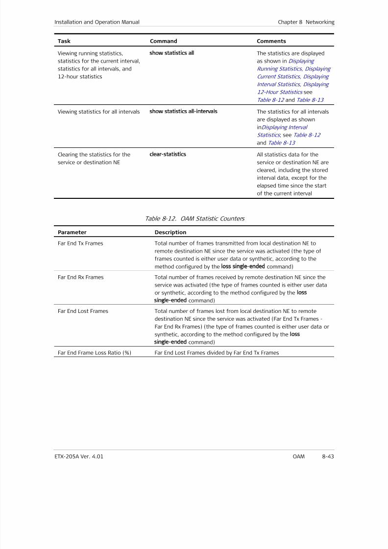
7/25/2019 Manual ETX-205A
http://slidepdf.com/reader/full/manual-etx-205a 229/409
Installation and Operation Manual Chapter 8 Networking
ETX-205A Ver. 4.01 OAM 8-43
Task Command Comments
Viewing running statistics,
statistics for the current interval,
statistics for all intervals, and
12-hour statistics
show statistics all The statistics are displayed
as shown in Displaying
Running Statistics, Displaying
Current Statistics, Displaying
Interval Statistics, Displaying
12-Hour Statistics seeTable 8-12 and Table 8-13
Viewing statistics for all intervals show statistics all-intervals The statistics for all intervals
are displayed as shown
inDisplaying Interval
Statistics ; see Table 8-12
and Table 8-13
Clearing the statistics for the
service or destination NE
clear-statistics All statistics data for the
service or destination NE are
cleared, including the stored
interval data, except for the
elapsed time since the start
of the current interval
Table 8-12. OAM Statistic Counters
Parameter Description
Far End Tx Frames Total number of frames transmitted from local destination NE to
remote destination NE since the service was activated (the type of
frames counted is either user data or synthetic, according to the
method configured by the loss single-ended command)
Far End Rx Frames Total number of frames received by remote destination NE since the
service was activated (the type of frames counted is either user data
or synthetic, according to the method configured by the loss
single-ended command)
Far End Lost Frames Total number of frames lost from local destination NE to remote
destination NE since the service was activated (Far End Tx Frames -
Far End Rx Frames) (the type of frames counted is either user data or
synthetic, according to the method configured by the loss
single-ended command)
Far End Frame Loss Ratio (%) Far End Lost Frames divided by Far End Tx Frames
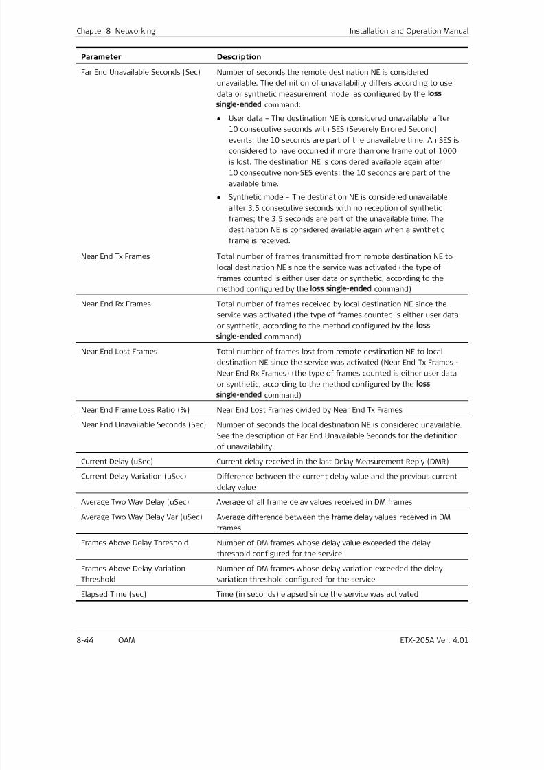
7/25/2019 Manual ETX-205A
http://slidepdf.com/reader/full/manual-etx-205a 230/409
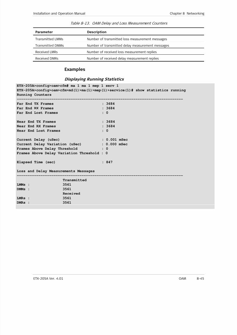
7/25/2019 Manual ETX-205A
http://slidepdf.com/reader/full/manual-etx-205a 231/409
Installation and Operation Manual Chapter 8 Networking
ETX-205A Ver. 4.01 OAM 8-45
Table 8-13. OAM Delay and Loss Measurement Counters
Parameter Description
Transmitted LMMs Number of transmitted loss measurement messages
Transmitted DMMs Number of transmitted delay measurement messages
Received LMRs Number of received loss measurement replies
Received DMRs Number of received delay measurement replies
Examples
Displaying Running Statistics
ETX-205A>config>oam>cfm# ma 1 ma 1 mep 1 serv 1
ETX-205A>config>oam>cfm>md(1)>ma(1)>mep(1)>service(1)# show statistics running
Running Counters
-----------------------------------------------------------------------------
Far End TX Frames : 3684
Far End RX Frames : 3684
Far End Lost Frames : 0
Near End TX Frames : 3684
Near End RX Frames : 3684
Near End Lost Frames : 0
Current Delay (uSec) : 0.001 mSec
Current Delay Variation (uSec) : 0.000 mSec
Frames Above Delay Threshold : 0
Frames Above Delay Variation Threshold : 0
Elapsed Time (sec) : 847
Loss and Delay Measurements Messages
-----------------------------------------------------------------------------
Transmitted
LMMs : 3561
DMMs : 3561
Received
LMRs : 3561
DMRs : 3561
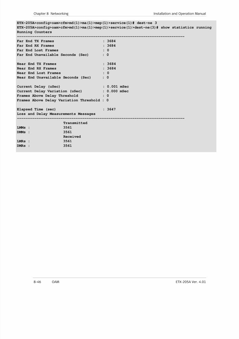
7/25/2019 Manual ETX-205A
http://slidepdf.com/reader/full/manual-etx-205a 232/409
Chapter 8 Networking Installation and Operation Manual
8-46 OAM ETX-205A Ver. 4.01
ETX-205A>config>oam>cfm>md(1)>ma(1)>mep(1)>service(1)# dest-ne 3
ETX-205A>config>oam>cfm>md(1)>ma(1)>mep(1)>service(1)>dest-ne(3)# show statistics running
Running Counters
-----------------------------------------------------------------------------
Far End TX Frames : 3684
Far End RX Frames : 3684
Far End Lost Frames : 0
Far End Unavailable Seconds (Sec) : 0
Near End TX Frames : 3684
Near End RX Frames : 3684
Near End Lost Frames : 0
Near End Unavailable Seconds (Sec) : 0
Current Delay (uSec) : 0.001 mSec
Current Delay Variation (uSec) : 0.000 mSec
Frames Above Delay Threshold : 0
Frames Above Delay Variation Threshold : 0
Elapsed Time (sec) : 3647
Loss and Delay Measurements Messages-----------------------------------------------------------------------------
Transmitted
LMMs : 3561
DMMs : 3561
Received
LMRs : 3561
DMRs : 3561
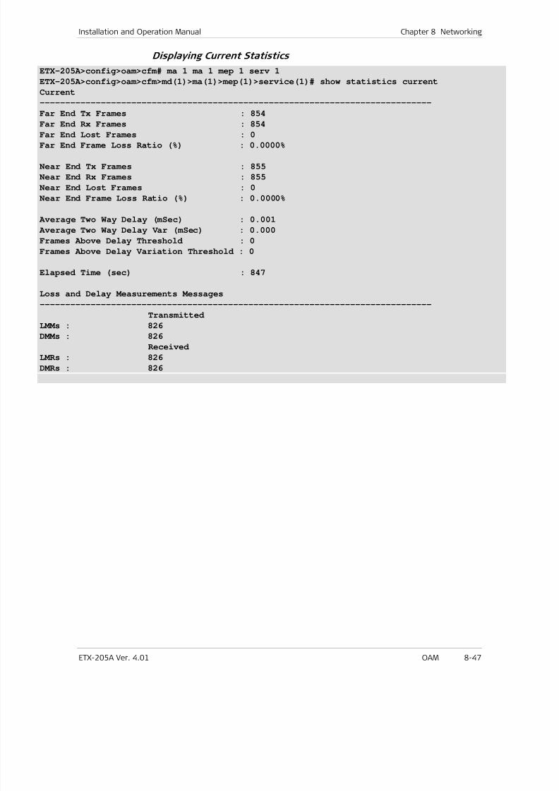
7/25/2019 Manual ETX-205A
http://slidepdf.com/reader/full/manual-etx-205a 233/409
Installation and Operation Manual Chapter 8 Networking
ETX-205A Ver. 4.01 OAM 8-47
Displaying Current Statistics
ETX-205A>config>oam>cfm# ma 1 ma 1 mep 1 serv 1
ETX-205A>config>oam>cfm>md(1)>ma(1)>mep(1)>service(1)# show statistics current
Current
-----------------------------------------------------------------------------
Far End Tx Frames : 854
Far End Rx Frames : 854
Far End Lost Frames : 0
Far End Frame Loss Ratio (%) : 0.0000%
Near End Tx Frames : 855
Near End Rx Frames : 855
Near End Lost Frames : 0
Near End Frame Loss Ratio (%) : 0.0000%
Average Two Way Delay (mSec) : 0.001
Average Two Way Delay Var (mSec) : 0.000
Frames Above Delay Threshold : 0
Frames Above Delay Variation Threshold : 0
Elapsed Time (sec) : 847
Loss and Delay Measurements Messages
-----------------------------------------------------------------------------
Transmitted
LMMs : 826
DMMs : 826
Received
LMRs : 826
DMRs : 826
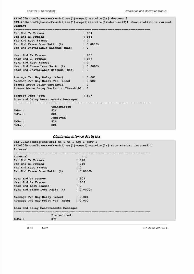
7/25/2019 Manual ETX-205A
http://slidepdf.com/reader/full/manual-etx-205a 234/409
Chapter 8 Networking Installation and Operation Manual
8-48 OAM ETX-205A Ver. 4.01
ETX-205A>config>oam>cfm>md(1)>ma(1)>mep(1)>service(1)# dest-ne 3
ETX-205A>config>oam>cfm>md(1)>ma(1)>mep(1)>service(1)>dest-ne(3)# show statistics current
Current
-----------------------------------------------------------------------------
Far End Tx Frames : 854
Far End Rx Frames : 854
Far End Lost Frames : 0
Far End Frame Loss Ratio (%) : 0.0000%Far End Unavailable Seconds (Sec) : 0
Near End Tx Frames : 855
Near End Rx Frames : 855
Near End Lost Frames : 0
Near End Frame Loss Ratio (%) : 0.0000%
Near End Unavailable Seconds (Sec) : 0
Average Two Way Delay (mSec) : 0.001
Average Two Way Delay Var (mSec) : 0.000
Frames Above Delay Threshold : 0
Frames Above Delay Variation Threshold : 0
Elapsed Time (sec) : 847
Loss and Delay Measurements Messages
-----------------------------------------------------------------------------
Transmitted
LMMs : 826
DMMs : 826
Received
LMRs : 826
DMRs : 826
Displaying Interval StatisticsETX-205A>config>oam>cfm# ma 1 ma 1 mep 1 serv 1
ETX-205A>config>oam>cfm>md(1)>ma(1)>mep(1)>service(1)# show statist interval 1
Interval
-----------------------------------------------------------------------------
Interval : 1
Far End Tx Frames : 910
Far End Rx Frames : 910
Far End Lost Frames : 0
Far End Frame Loss Ratio (%) : 0.0000%
Near End Tx Frames : 909
Near End Rx Frames : 909Near End Lost Frames : 0
Near End Frame Loss Ratio (%) : 0.0000%
Average Two Way Delay (mSec) : 0.001
Average Two Way Delay Var (mSec) : 0.000
Loss and Delay Measurements Messages
-----------------------------------------------------------------------------
Transmitted
LMMs : 879
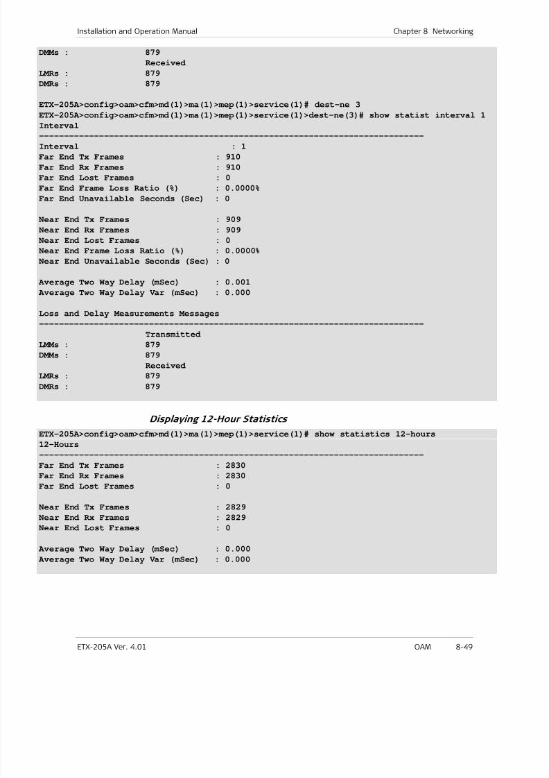
7/25/2019 Manual ETX-205A
http://slidepdf.com/reader/full/manual-etx-205a 235/409
Installation and Operation Manual Chapter 8 Networking
ETX-205A Ver. 4.01 OAM 8-49
DMMs : 879
Received
LMRs : 879
DMRs : 879
ETX-205A>config>oam>cfm>md(1)>ma(1)>mep(1)>service(1)# dest-ne 3
ETX-205A>config>oam>cfm>md(1)>ma(1)>mep(1)>service(1)>dest-ne(3)# show statist interval 1
Interval-----------------------------------------------------------------------------
Interval : 1
Far End Tx Frames : 910
Far End Rx Frames : 910
Far End Lost Frames : 0
Far End Frame Loss Ratio (%) : 0.0000%
Far End Unavailable Seconds (Sec) : 0
Near End Tx Frames : 909
Near End Rx Frames : 909
Near End Lost Frames : 0
Near End Frame Loss Ratio (%) : 0.0000%
Near End Unavailable Seconds (Sec) : 0
Average Two Way Delay (mSec) : 0.001
Average Two Way Delay Var (mSec) : 0.000
Loss and Delay Measurements Messages
-----------------------------------------------------------------------------
Transmitted
LMMs : 879
DMMs : 879
Received
LMRs : 879
DMRs : 879
Displaying 12-Hour Statistics
ETX-205A>config>oam>cfm>md(1)>ma(1)>mep(1)>service(1)# show statistics 12-hours
12-Hours
-----------------------------------------------------------------------------
Far End Tx Frames : 2830
Far End Rx Frames : 2830
Far End Lost Frames : 0
Near End Tx Frames : 2829
Near End Rx Frames : 2829Near End Lost Frames : 0
Average Two Way Delay (mSec) : 0.000
Average Two Way Delay Var (mSec) : 0.000
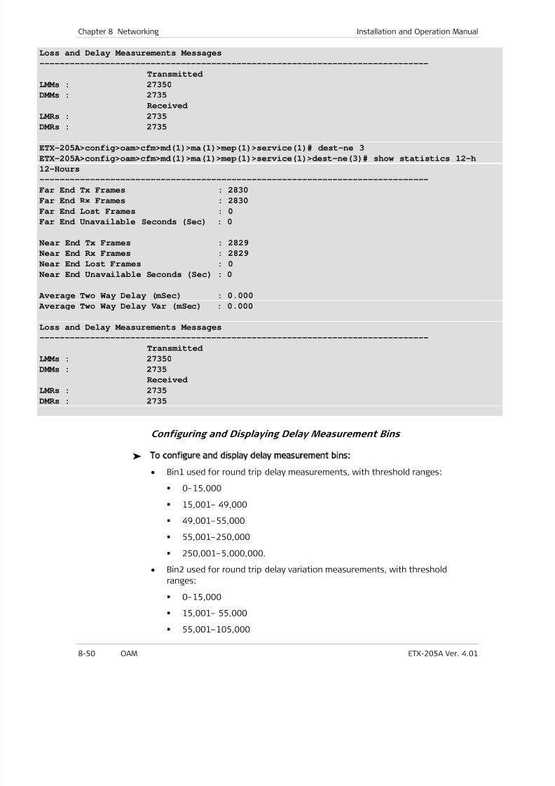
7/25/2019 Manual ETX-205A
http://slidepdf.com/reader/full/manual-etx-205a 236/409
Chapter 8 Networking Installation and Operation Manual
8-50 OAM ETX-205A Ver. 4.01
Loss and Delay Measurements Messages
-----------------------------------------------------------------------------
Transmitted
LMMs : 27350
DMMs : 2735
Received
LMRs : 2735
DMRs : 2735
ETX-205A>config>oam>cfm>md(1)>ma(1)>mep(1)>service(1)# dest-ne 3
ETX-205A>config>oam>cfm>md(1)>ma(1)>mep(1)>service(1)>dest-ne(3)# show statistics 12-h
12-Hours
-----------------------------------------------------------------------------
Far End Tx Frames : 2830
Far End Rx Frames : 2830
Far End Lost Frames : 0
Far End Unavailable Seconds (Sec) : 0
Near End Tx Frames : 2829
Near End Rx Frames : 2829
Near End Lost Frames : 0Near End Unavailable Seconds (Sec) : 0
Average Two Way Delay (mSec) : 0.000
Average Two Way Delay Var (mSec) : 0.000
Loss and Delay Measurements Messages
-----------------------------------------------------------------------------
Transmitted
LMMs : 27350
DMMs : 2735
Received
LMRs : 2735DMRs : 2735
Configuring and Displaying Delay Measurement Bins
To configure and display delay measurement bins:
• Bin1 used for round trip delay measurements, with threshold ranges:
0–15,000
15,001– 49,000
49,001–55,000 55,001–250,000
250,001–5,000,000.
• Bin2 used for round trip delay variation measurements, with threshold
ranges:
0–15,000
15,001– 55,000
55,001–105,000
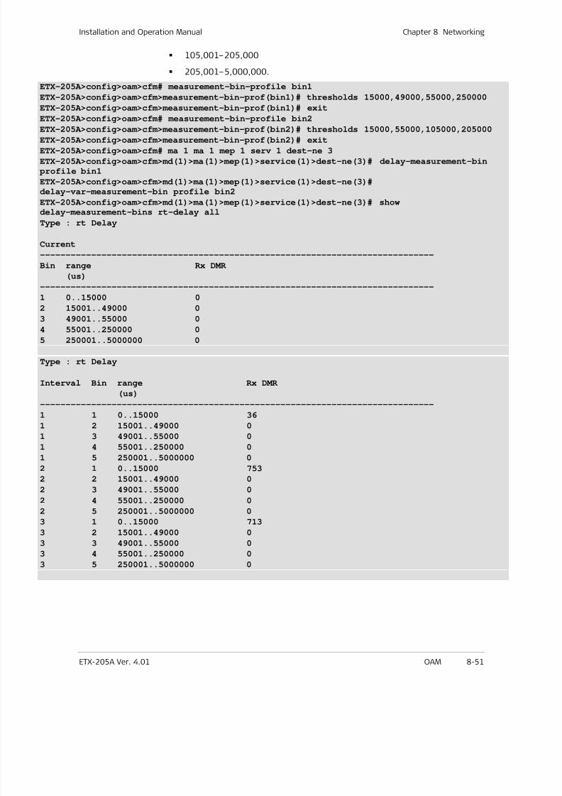
7/25/2019 Manual ETX-205A
http://slidepdf.com/reader/full/manual-etx-205a 237/409
Installation and Operation Manual Chapter 8 Networking
ETX-205A Ver. 4.01 OAM 8-51
105,001–205,000
205,001–5,000,000.
ETX-205A>config>oam>cfm# measurement-bin-profile bin1
ETX-205A>config>oam>cfm>measurement-bin-prof(bin1)# thresholds 15000,49000,55000,250000
ETX-205A>config>oam>cfm>measurement-bin-prof(bin1)# exit
ETX-205A>config>oam>cfm# measurement-bin-profile bin2
ETX-205A>config>oam>cfm>measurement-bin-prof(bin2)# thresholds 15000,55000,105000,205000ETX-205A>config>oam>cfm>measurement-bin-prof(bin2)# exit
ETX-205A>config>oam>cfm# ma 1 ma 1 mep 1 serv 1 dest-ne 3
ETX-205A>config>oam>cfm>md(1)>ma(1)>mep(1)>service(1)>dest-ne(3)# delay-measurement-bin
profile bin1
ETX-205A>config>oam>cfm>md(1)>ma(1)>mep(1)>service(1)>dest-ne(3)#
delay-var-measurement-bin profile bin2
ETX-205A>config>oam>cfm>md(1)>ma(1)>mep(1)>service(1)>dest-ne(3)# showdelay-measurement-bins rt-delay all
Type : rt Delay
Current
-----------------------------------------------------------------------------
Bin range Rx DMR(us)
-----------------------------------------------------------------------------
1 0..15000 0
2 15001..49000 0
3 49001..55000 0
4 55001..250000 0
5 250001..5000000 0
Type : rt Delay
Interval Bin range Rx DMR
(us)-----------------------------------------------------------------------------
1 1 0..15000 36
1 2 15001..49000 0
1 3 49001..55000 0
1 4 55001..250000 0
1 5 250001..5000000 0
2 1 0..15000 753
2 2 15001..49000 0
2 3 49001..55000 0
2 4 55001..250000 0
2 5 250001..5000000 0
3 1 0..15000 713
3 2 15001..49000 0
3 3 49001..55000 0
3 4 55001..250000 0
3 5 250001..5000000 0
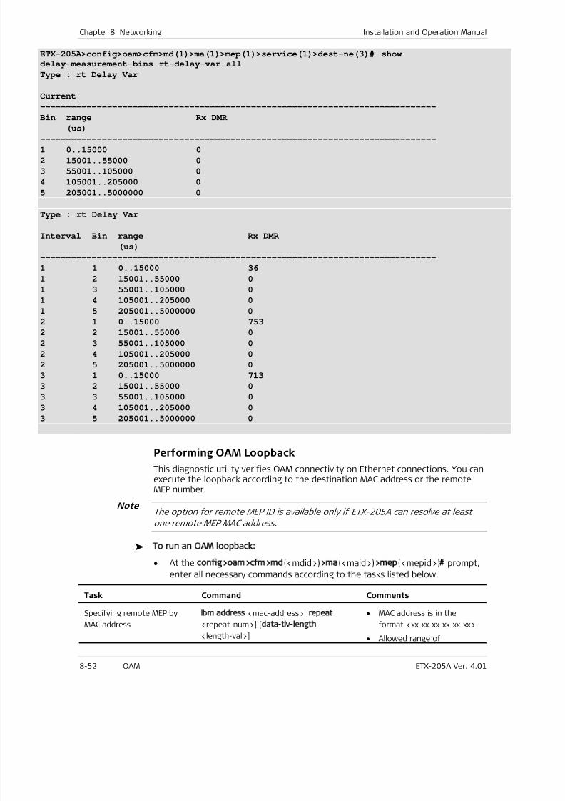
7/25/2019 Manual ETX-205A
http://slidepdf.com/reader/full/manual-etx-205a 238/409
Chapter 8 Networking Installation and Operation Manual
8-52 OAM ETX-205A Ver. 4.01
ETX-205A>config>oam>cfm>md(1)>ma(1)>mep(1)>service(1)>dest-ne(3)# show
delay-measurement-bins rt-delay-var all
Type : rt Delay Var
Current
-----------------------------------------------------------------------------
Bin range Rx DMR
(us)
-----------------------------------------------------------------------------
1 0..15000 0
2 15001..55000 0
3 55001..105000 0
4 105001..205000 0
5 205001..5000000 0
Type : rt Delay Var
Interval Bin range Rx DMR
(us)
-----------------------------------------------------------------------------
1 1 0..15000 361 2 15001..55000 0
1 3 55001..105000 0
1 4 105001..205000 0
1 5 205001..5000000 0
2 1 0..15000 753
2 2 15001..55000 0
2 3 55001..105000 0
2 4 105001..205000 0
2 5 205001..5000000 0
3 1 0..15000 713
3 2 15001..55000 0
3 3 55001..105000 03 4 105001..205000 0
3 5 205001..5000000 0
Performing OAM Loopback
This diagnostic utility verifies OAM connectivity on Ethernet connections. You canexecute the loopback according to the destination MAC address or the remoteMEP number.
The option for remote MEP ID is available only if ETX-205A can resolve at least
one remote MEP MAC address.
To run an OAM loopback:
• At the config>oam>cfm>md(<mdid>)>ma(<maid>)>mep(<mepid>)# prompt,
enter all necessary commands according to the tasks listed below.
Task Command Comments
Specifying remote MEP by
MAC address
lbm address <mac-address> [repeat
<repeat-num>] [data-tlv-length
<length-val>]
• MAC address is in the
format <xx-xx-xx-xx-xx-xx>
• Allowed range of
Note
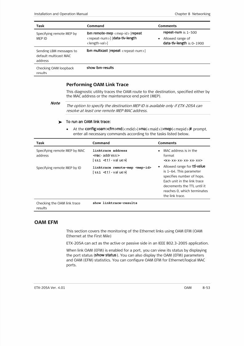
7/25/2019 Manual ETX-205A
http://slidepdf.com/reader/full/manual-etx-205a 239/409
Installation and Operation Manual Chapter 8 Networking
ETX-205A Ver. 4.01 OAM 8-53
Task Command Comments
Specifying remote MEP by
MEP ID
lbm remote-mep <mep-id> [repeat
<repeat-num>] [data-tlv-length
<length-val>]
repeat-num is 1–500
• Allowed range of
data-tlv-length is 0–1900
Sending LBM messages to
default multicast MACaddress
lbm multicast [repeat <repeat-num>]
Checking OAM loopback
results
show lbm-results
Performing OAM Link Trace
This diagnostic utility traces the OAM route to the destination, specified either bythe MAC address or the maintenance end point (MEP).
The option to specify the destination MEP ID is available only if ETX-205A can
resolve at least one remote MEP MAC address.
To run an OAM link trace:
• At the config>oam>cfm>md(<mdid>)>ma(<maid>)>mep(<mepid>)# prompt,
enter all necessary commands according to the tasks listed below.
Task Command Comments
Specifying remote MEP by MAC
address
linktrace address
<mac- address>
[ ttl <t t l - val ue>]
• MAC address is in the
format
<xx- xx- xx- xx- xx- xx>
• Allowed range for ttl-value
is 1–64. This parameterspecifies number of hops.
Each unit in the link trace
decrements the TTL until it
reaches 0, which terminates
the link trace.
Specifying remote MEP by ID linktrace remote-mep <mep-id>
[ ttl <t t l - val ue>]
Checking the OAM link trace
results
show linktrace-results
OAM EFM
This section covers the monitoring of the Ethernet links using OAM EFM (OAMEthernet at the First Mile)
ETX-205A can act as the active or passive side in an IEEE 802.3-2005 application.
When link OAM (EFM) is enabled for a port, you can view its status by displaying
the port status (show status). You can also display the OAM (EFM) parameters
and OAM (EFM) statistics. You can configure OAM EFM for Ethernet/logical MAC
ports.
Note
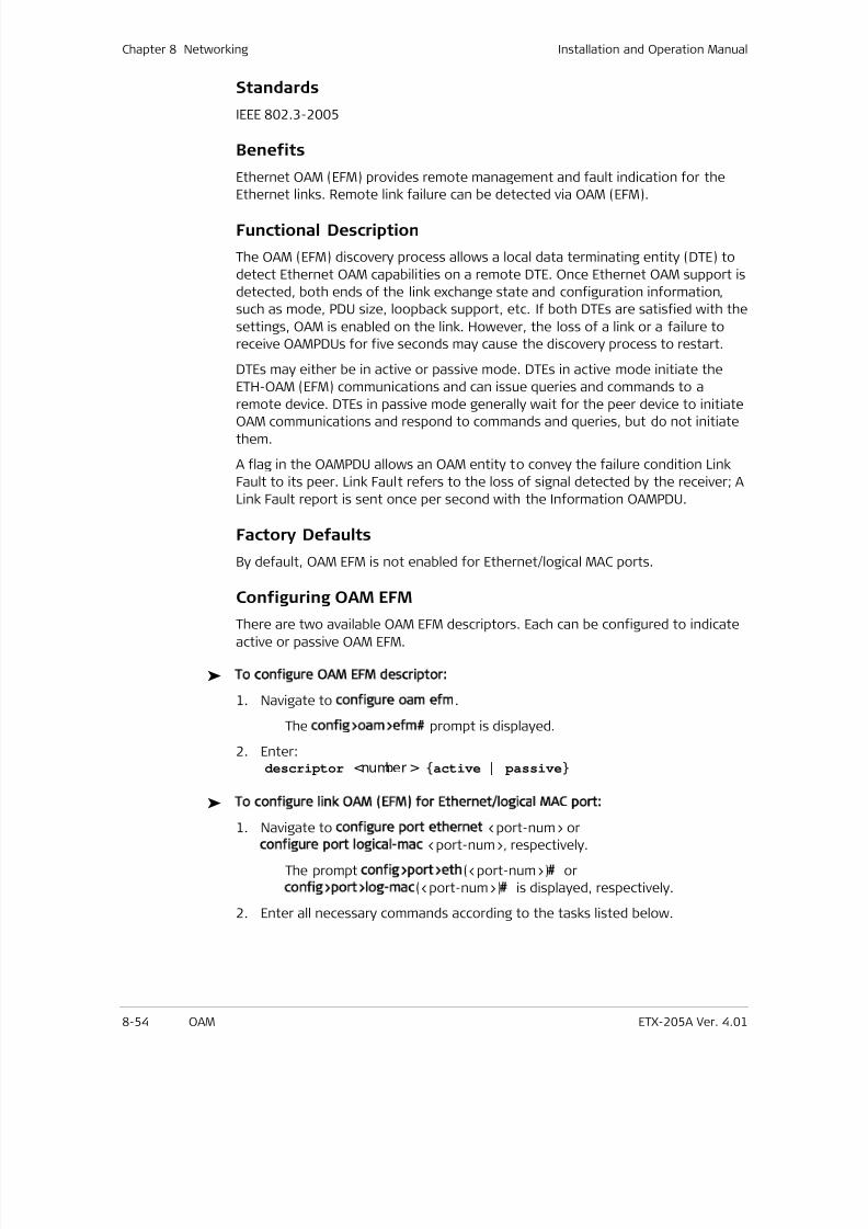
7/25/2019 Manual ETX-205A
http://slidepdf.com/reader/full/manual-etx-205a 240/409
Chapter 8 Networking Installation and Operation Manual
8-54 OAM ETX-205A Ver. 4.01
Standards
IEEE 802.3-2005
Benefits
Ethernet OAM (EFM) provides remote management and fault indication for the
Ethernet links. Remote link failure can be detected via OAM (EFM).
Functional Description
The OAM (EFM) discovery process allows a local data terminating entity (DTE) to
detect Ethernet OAM capabilities on a remote DTE. Once Ethernet OAM support is
detected, both ends of the link exchange state and configuration information,
such as mode, PDU size, loopback support, etc. If both DTEs are satisfied with the
settings, OAM is enabled on the link. However, the loss of a link or a failure to
receive OAMPDUs for five seconds may cause the discovery process to restart.
DTEs may either be in active or passive mode. DTEs in active mode initiate the
ETH-OAM (EFM) communications and can issue queries and commands to a
remote device. DTEs in passive mode generally wait for the peer device to initiateOAM communications and respond to commands and queries, but do not initiate
them.
A flag in the OAMPDU allows an OAM entity to convey the failure condition Link
Fault to its peer. Link Fault refers to the loss of signal detected by the receiver; A
Link Fault report is sent once per second with the Information OAMPDU.
Factory Defaults
By default, OAM EFM is not enabled for Ethernet/logical MAC ports.
Configuring OAM EFM
There are two available OAM EFM descriptors. Each can be configured to indicate
active or passive OAM EFM.
To configure OAM EFM descriptor:
1. Navigate to configure oam efm.
The config>oam>efm# prompt is displayed.
2. Enter:descriptor <number > active | passive
To configure link OAM (EFM) for Ethernet/logical MAC port:
1. Navigate to configure port ethernet <port-num> or
configure port logical-mac <port-num>, respectively.
The prompt config>port>eth(<port-num>)# or
config>port>log-mac(<port-num>)# is displayed, respectively.
2. Enter all necessary commands according to the tasks listed below.
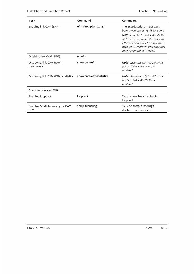
7/25/2019 Manual ETX-205A
http://slidepdf.com/reader/full/manual-etx-205a 241/409
Installation and Operation Manual Chapter 8 Networking
ETX-205A Ver. 4.01 OAM 8-55
Task Command Comments
Enabling link OAM (EFM) efm descriptor <1–2> The EFM descriptor must exist
before you can assign it to a port
Note
: In order for link OAM (EFM)
to function properly, the relevant
Ethernet port must be associated
with an L2CP profile that specifies
peer action for MAC 0x02.
Disabling link OAM (EFM) no efm
Displaying link OAM (EFM)
parameters
show oam-efm
Note
: Relevant only for Ethernet
ports, if link OAM (EFM) is
enabled.
Displaying link OAM (EFM) statistics show oam-efm-statistics
Note
: Relevant only for Ethernet
ports, if link OAM (EFM) is
enabled.
Commands in level efm
Enabling loopback loopback Type no loopback to disable
loopback
Enabling SNMP tunneling for OAM
EFM
snmp-tunneling Type no snmp-tunneling to
disable snmp tunneling
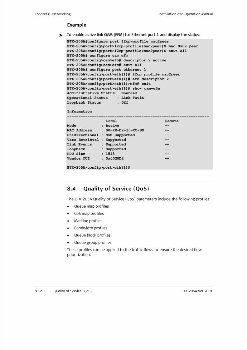
7/25/2019 Manual ETX-205A
http://slidepdf.com/reader/full/manual-etx-205a 242/409
Chapter 8 Networking Installation and Operation Manual
8-56 Quality of Service (QoS) ETX-205A Ver. 4.01
Example
To enable active link OAM (EFM) for Ethernet port 1 and display the status:
ETX-205A#configure port l2cp-profile mac2peer
ETX-205A>config>port>l2cp-profile(mac2peer)$ mac 0x02 peer
ETX-205A>config>port>l2cp-profile(mac2peer)$ exit all
ETX-205A# configure oam efm
ETX-205A>config>oam>efm# descriptor 2 active
ETX-205A>config>oam>efm# exit all
ETX-205A# configure port ethernet 1
ETX-205A>config>port>eth(1)# l2cp profile mac2peer
ETX-205A>config>port>eth(1)# efm descriptor 2
ETX-205A>config>port>eth(1)>efm# exit
ETX-205A>config>port>eth(1)# show oam-efm
Administrative Status : Enabled
Operational Status : Link Fault
Loopback Status : Off
Information
---------------------------------------------------------------Local Remote
Mode : Active --
MAC Address : 00-20-D2-30-CC-9D --
Unidirectional : Not Supported --
Vars Retrieval : Supported --
Link Events : Supported --
Loopback : Supported --
PDU Size : 1518 --
Vendor OUI : 0x0020D2 --
ETX-205A>config>port>eth(1)#
8.4 Quality of Service (QoS)
The ETX-205A Quality of Service (QoS) parameters include the following profiles:
• Queue map profiles
• CoS map profiles
• Marking profiles
• Bandwidth profiles
• Queue block profiles
• Queue group profiles.
These profiles can be applied to the traffic flows to ensure the desired flow
prioritization.

7/25/2019 Manual ETX-205A
http://slidepdf.com/reader/full/manual-etx-205a 243/409
Installation and Operation Manual Chapter 8 Networking
ETX-205A Ver. 4.01 Quality of Service (QoS) 8-57
Standards
The following standards are supported:
• IEEE 802.1p
• IEEE 802.1Q.
Benefits
QoS allows you to optimize bandwidth, avoiding the need to allocate excessive
bandwidth to facilitate the necessary bandwidth for traffic at different
requirements of speed and quality.
Factory Defaults
See the following sections for each QoS type’s specific defaults.
Functional DescriptionTo differentiate traffic, the IEEE 802.1p standard specifies eight classes of service
per user-defined queue map profile. These classes of service are associated with
priority values between 0 and 7, using the 3-bit user priority field in an
IEEE 802.1Q header added to VLAN-tagged frames within an Ethernet frame
header. The way traffic is treated when assigned to a specific priority value is
only generally defined and left to implementation. The general definitions are as
follows:
Table 8-14. User Priorities
User Priority Traffic Type
0 Best effort
1 Background
2 Spare
3 Excellent effort
4 Controlled load
5 Video
6 Voice
7 Network control
Queue Mapping Profiles
Queue mapping profiles are used to convert the following user priorities into
internal priority queues. ETX-205A supports up to 12 queue mapping profiles.
• p-bit, when the ingress traffic is prioritized according to the 802.1p
requirements
• ip-dscp, when the ingress traffic is prioritized according to DSCP
7/25/2019 Manual ETX-205A
http://slidepdf.com/reader/full/manual-etx-205a 244/409
Chapter 8 Networking Installation and Operation Manual
8-58 Quality of Service (QoS) ETX-205A Ver. 4.01
• ip-precedence, when the ingress traffic is prioritized according to
IP precedence
• Class of Service (CoS), to queue ETP flow according to internal class of
service.
For each profile, you have to define the queue mapping to map the user priority
values to the internal queue values. The internal queues are combined into a
queue profile, which can be assigned to a queue block.
Factory Defaults
Default Queue Mapping Profile
ETX-205A provides a default queue mapping profile named CosProfile1, which can
be used when the ingress traffic is prioritized according to the 802.1p
requirements. It is defined with classification p-bit, and the following mappings:
• Map p-bit 0 to queue 7
• Map p-bit 1 to queue 6
• Map p-bit 2 to queue 5
• Map p-bit 3 to queue 4
• Map p-bit 4 to queue 3
• Map p-bit 5 to queue 2
• Map p-bit 6 to queue 1
• Map p-bit 7 to queue 0.
Default Configuration for IP Precedence Classification
When a new queue mapping profile is created with classification IP precedence, it
contains the following mappings:
• Map p-bit 0 to queue 7
• Map p-bit 1 to queue 6
• Map p-bit 2 to queue 5
• Map p-bit 3 to queue 4
• Map p-bit 4 to queue 3
• Map p-bit 5 to queue 2
• Map p-bit 6 to queue 1
• Map p-bit 7 to queue 0.
Default Configuration for DSCP Classification
When a new queue mapping profile is created with classification DSCP, it contains
the following mappings:
• Map p-bit 0 to queue 7
• Map p-bit 1 to queue 6
• Map p-bit 2 to queue 5
7/25/2019 Manual ETX-205A
http://slidepdf.com/reader/full/manual-etx-205a 245/409
Installation and Operation Manual Chapter 8 Networking
ETX-205A Ver. 4.01 Quality of Service (QoS) 8-59
• Map p-bit 3 to queue 4
• Map p-bit 4 to queue 3
• Map p-bit 5 to queue 2
• Map p-bit 6 to queue 1
• Map p-bit 7 through 63 to queue 0.
Adding Queue Mapping Profiles
When you create a queue mapping profile, you specify the name and the
classification method (p-bit, IP precedence, or DSCP).
To add a queue mapping profile:
1. Navigate to configure qos.
The config>qos# prompt is displayed.
2. Type:queue-map-profile <queue- map- prof i l e- name> classification
p- bi t | i p- pr ecedence| i p- dscp| cos
A queue mapping profile with the specified name and classification
method is created and the following prompt is displayed:config>qos>queue-map-profile( <queue- map- prof i l e- name>) $.
The mappings for the new profile are configured by default as described
in Factory Defaults .
3. Configure the queue profile mappings as described in Configuring Queue
Mappings .
Configuring Queue Mappings
1. Navigate to config qos queue-map-profile <queue-map-profile-name> toselect the queue mapping profile to configure.
The following prompt is displayed:
config>qos>queue-map-profile(<queue-map-profile-name>)#
2. Map the user priorities to queue IDs as necessary:
Classification p-bit or IP precedence: map <0- 7> to-queue <0- 7>
Classification DSCP: map <0- 63> to-queue <0- 7>
Classification CoS: map <0- 7> to-queue <0- 7>
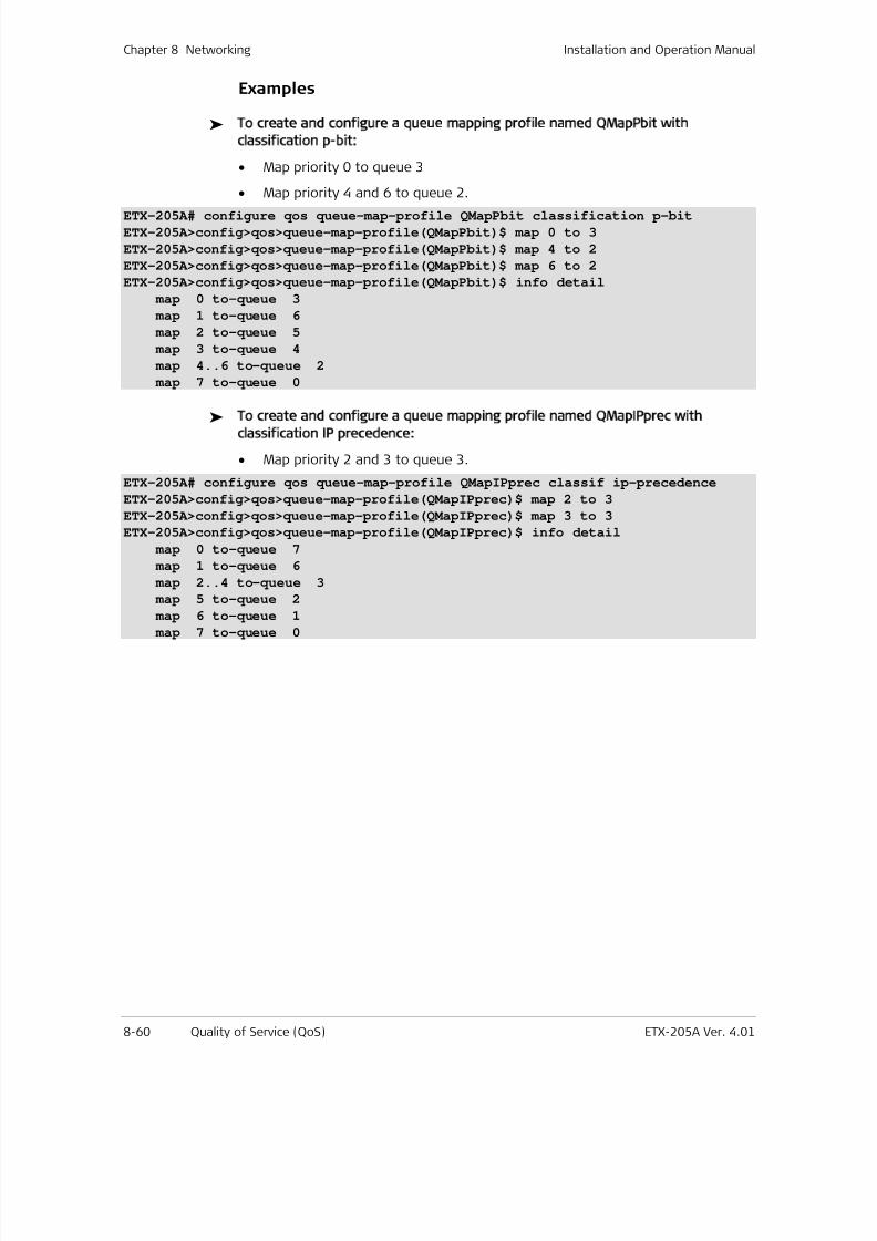
7/25/2019 Manual ETX-205A
http://slidepdf.com/reader/full/manual-etx-205a 246/409
Chapter 8 Networking Installation and Operation Manual
8-60 Quality of Service (QoS) ETX-205A Ver. 4.01
Examples
To create and configure a queue mapping profile named QMapPbit with
classification p-bit:
• Map priority 0 to queue 3
• Map priority 4 and 6 to queue 2.
ETX-205A# configure qos queue-map-profile QMapPbit classification p-bit
ETX-205A>config>qos>queue-map-profile(QMapPbit)$ map 0 to 3
ETX-205A>config>qos>queue-map-profile(QMapPbit)$ map 4 to 2
ETX-205A>config>qos>queue-map-profile(QMapPbit)$ map 6 to 2
ETX-205A>config>qos>queue-map-profile(QMapPbit)$ info detail
map 0 to-queue 3
map 1 to-queue 6
map 2 to-queue 5
map 3 to-queue 4
map 4..6 to-queue 2
map 7 to-queue 0
To create and configure a queue mapping profile named QMapIPprec with
classification IP precedence:
• Map priority 2 and 3 to queue 3.
ETX-205A# configure qos queue-map-profile QMapIPprec classif ip-precedence
ETX-205A>config>qos>queue-map-profile(QMapIPprec)$ map 2 to 3
ETX-205A>config>qos>queue-map-profile(QMapIPprec)$ map 3 to 3
ETX-205A>config>qos>queue-map-profile(QMapIPprec)$ info detail
map 0 to-queue 7
map 1 to-queue 6
map 2..4 to-queue 3
map 5 to-queue 2
map 6 to-queue 1 map 7 to-queue 0
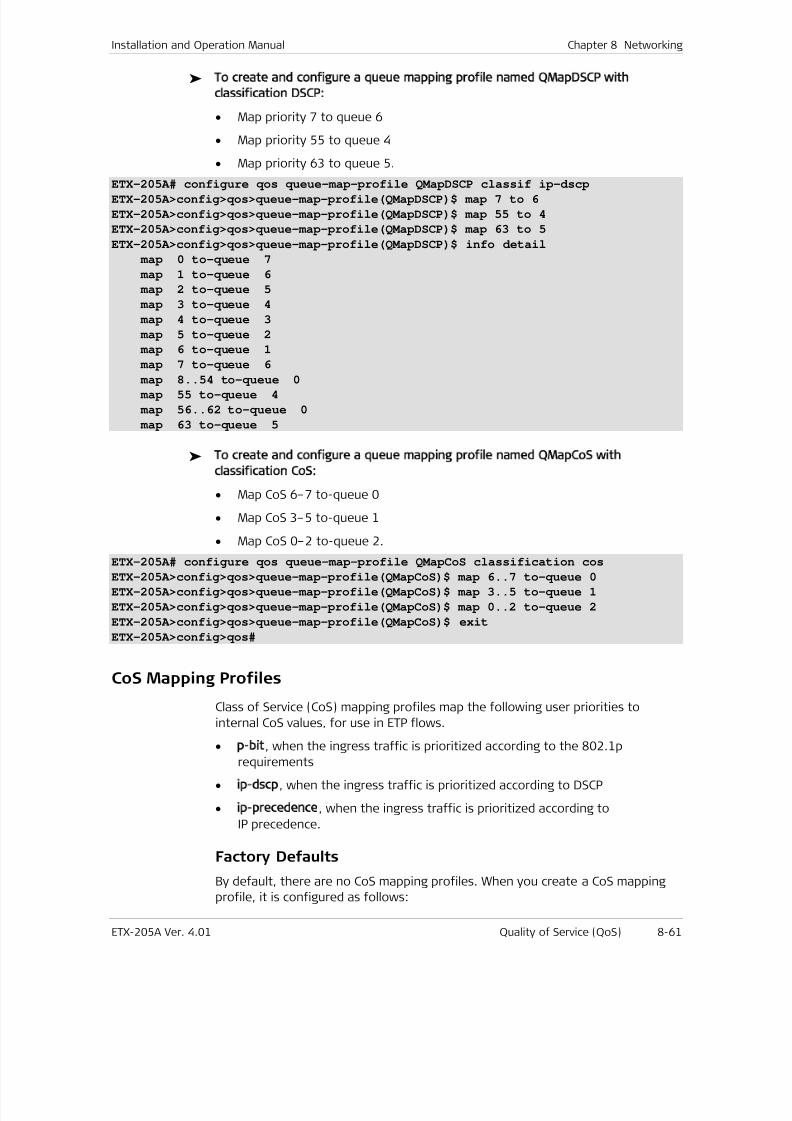
7/25/2019 Manual ETX-205A
http://slidepdf.com/reader/full/manual-etx-205a 247/409
Installation and Operation Manual Chapter 8 Networking
ETX-205A Ver. 4.01 Quality of Service (QoS) 8-61
To create and configure a queue mapping profile named QMapDSCP with
classification DSCP:
• Map priority 7 to queue 6
• Map priority 55 to queue 4
• Map priority 63 to queue 5.
ETX-205A# configure qos queue-map-profile QMapDSCP classif ip-dscpETX-205A>config>qos>queue-map-profile(QMapDSCP)$ map 7 to 6
ETX-205A>config>qos>queue-map-profile(QMapDSCP)$ map 55 to 4
ETX-205A>config>qos>queue-map-profile(QMapDSCP)$ map 63 to 5
ETX-205A>config>qos>queue-map-profile(QMapDSCP)$ info detail
map 0 to-queue 7
map 1 to-queue 6
map 2 to-queue 5
map 3 to-queue 4
map 4 to-queue 3
map 5 to-queue 2
map 6 to-queue 1
map 7 to-queue 6
map 8..54 to-queue 0
map 55 to-queue 4
map 56..62 to-queue 0
map 63 to-queue 5
To create and configure a queue mapping profile named QMapCoS with
classification CoS:
• Map CoS 6–7 to-queue 0
• Map CoS 3–5 to-queue 1
• Map CoS 0–2 to-queue 2.
ETX-205A# configure qos queue-map-profile QMapCoS classification cosETX-205A>config>qos>queue-map-profile(QMapCoS)$ map 6..7 to-queue 0
ETX-205A>config>qos>queue-map-profile(QMapCoS)$ map 3..5 to-queue 1
ETX-205A>config>qos>queue-map-profile(QMapCoS)$ map 0..2 to-queue 2
ETX-205A>config>qos>queue-map-profile(QMapCoS)$ exit
ETX-205A>config>qos#
CoS Mapping Profiles
Class of Service (CoS) mapping profiles map the following user priorities to
internal CoS values, for use in ETP flows.
• p-bit, when the ingress traffic is prioritized according to the 802.1prequirements
• ip-dscp, when the ingress traffic is prioritized according to DSCP
• ip-precedence, when the ingress traffic is prioritized according to
IP precedence.
Factory Defaults
By default, there are no CoS mapping profiles. When you create a CoS mapping
profile, it is configured as follows:
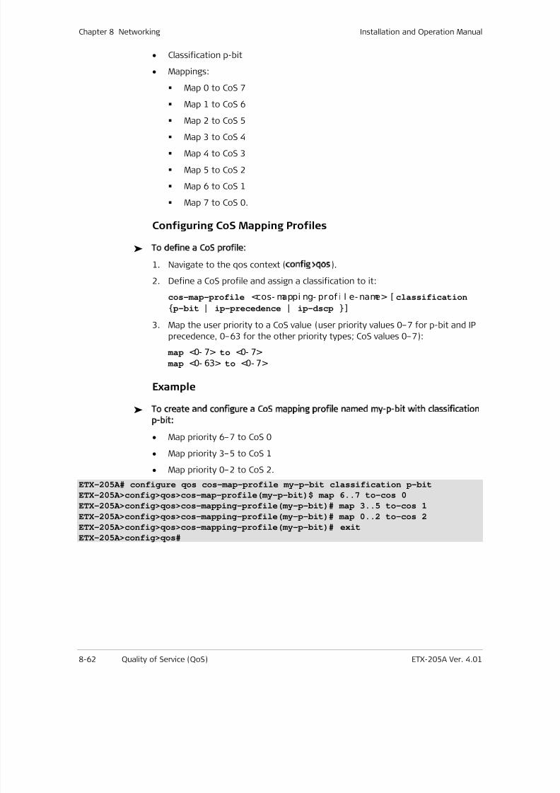
7/25/2019 Manual ETX-205A
http://slidepdf.com/reader/full/manual-etx-205a 248/409
Chapter 8 Networking Installation and Operation Manual
8-62 Quality of Service (QoS) ETX-205A Ver. 4.01
• Classification p-bit
• Mappings:
Map 0 to CoS 7
Map 1 to CoS 6
Map 2 to CoS 5
Map 3 to CoS 4
Map 4 to CoS 3
Map 5 to CoS 2
Map 6 to CoS 1
Map 7 to CoS 0.
Configuring CoS Mapping Profiles
To define a CoS profile:
1. Navigate to the qos context (config>qos).
2. Define a CoS profile and assign a classification to it:
cos-map-profile <cos- mappi ng- prof i l e- name> [ classification
p-bit | ip-precedence | ip-dscp ]
3. Map the user priority to a CoS value (user priority values 0–7 for p-bit and IP
precedence, 0–63 for the other priority types; CoS values 0–7):
map <0- 7> to <0- 7>
map <0- 63> to <0- 7>
Example
To create and configure a CoS mapping profile named my-p-bit with classification
p-bit:
• Map priority 6–7 to CoS 0
• Map priority 3–5 to CoS 1
• Map priority 0–2 to CoS 2.
ETX-205A# configure qos cos-map-profile my-p-bit classification p-bit
ETX-205A>config>qos>cos-map-profile(my-p-bit)$ map 6..7 to-cos 0
ETX-205A>config>qos>cos-mapping-profile(my-p-bit)# map 3..5 to-cos 1
ETX-205A>config>qos>cos-mapping-profile(my-p-bit)# map 0..2 to-cos 2
ETX-205A>config>qos>cos-mapping-profile(my-p-bit)# exitETX-205A>config>qos#
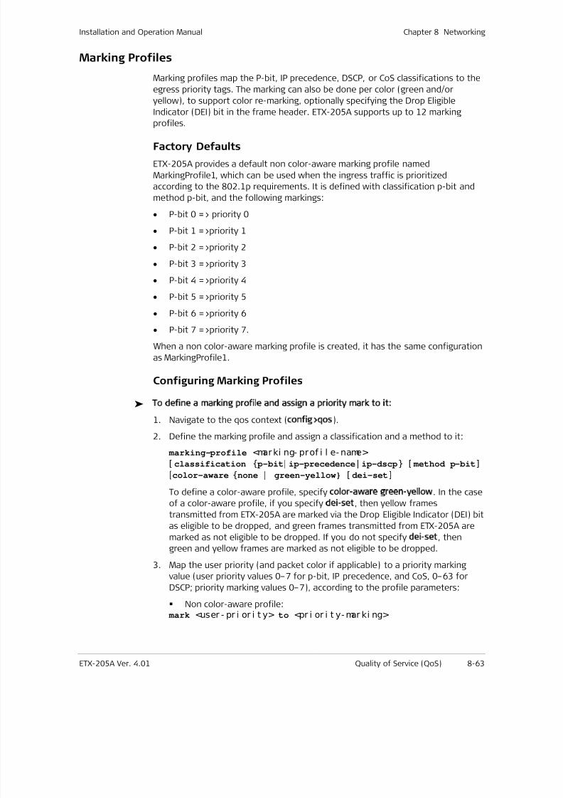
7/25/2019 Manual ETX-205A
http://slidepdf.com/reader/full/manual-etx-205a 249/409
Installation and Operation Manual Chapter 8 Networking
ETX-205A Ver. 4.01 Quality of Service (QoS) 8-63
Marking Profiles
Marking profiles map the P-bit, IP precedence, DSCP, or CoS classifications to the
egress priority tags. The marking can also be done per color (green and/or
yellow), to support color re-marking, optionally specifying the Drop Eligible
Indicator (DEI) bit in the frame header. ETX-205A supports up to 12 marking
profiles.
Factory Defaults
ETX-205A provides a default non color-aware marking profile named
MarkingProfile1, which can be used when the ingress traffic is prioritized
according to the 802.1p requirements. It is defined with classification p-bit and
method p-bit, and the following markings:
• P-bit 0 => priority 0
• P-bit 1 =>priority 1
• P-bit 2 =>priority 2
• P-bit 3 =>priority 3
• P-bit 4 =>priority 4
• P-bit 5 =>priority 5
• P-bit 6 =>priority 6
• P-bit 7 =>priority 7.
When a non color-aware marking profile is created, it has the same configuration
as MarkingProfile1.
Configuring Marking Profiles
To define a marking profile and assign a priority mark to it:
1. Navigate to the qos context (config>qos).
2. Define the marking profile and assign a classification and a method to it:
marking-profile <marki ng- prof i l e- name>
[ classification p-bit| ip-precedence| ip-dscp [ method p-bit]
[color-aware none | green-yellow [ dei-set]
To define a color-aware profile, specify color-aware green-yellow. In the case
of a color-aware profile, if you specify dei-set, then yellow frames
transmitted from ETX-205A are marked via the Drop Eligible Indicator (DEI) bit
as eligible to be dropped, and green frames transmitted from ETX-205A aremarked as not eligible to be dropped. If you do not specify dei-set, then
green and yellow frames are marked as not eligible to be dropped.
3. Map the user priority (and packet color if applicable) to a priority marking
value (user priority values 0–7 for p-bit, IP precedence, and CoS, 0–63 for
DSCP; priority marking values 0–7), according to the profile parameters:
Non color-aware profile: mark <user - pr i or i t y> to <pr i or i t y- mar ki ng>
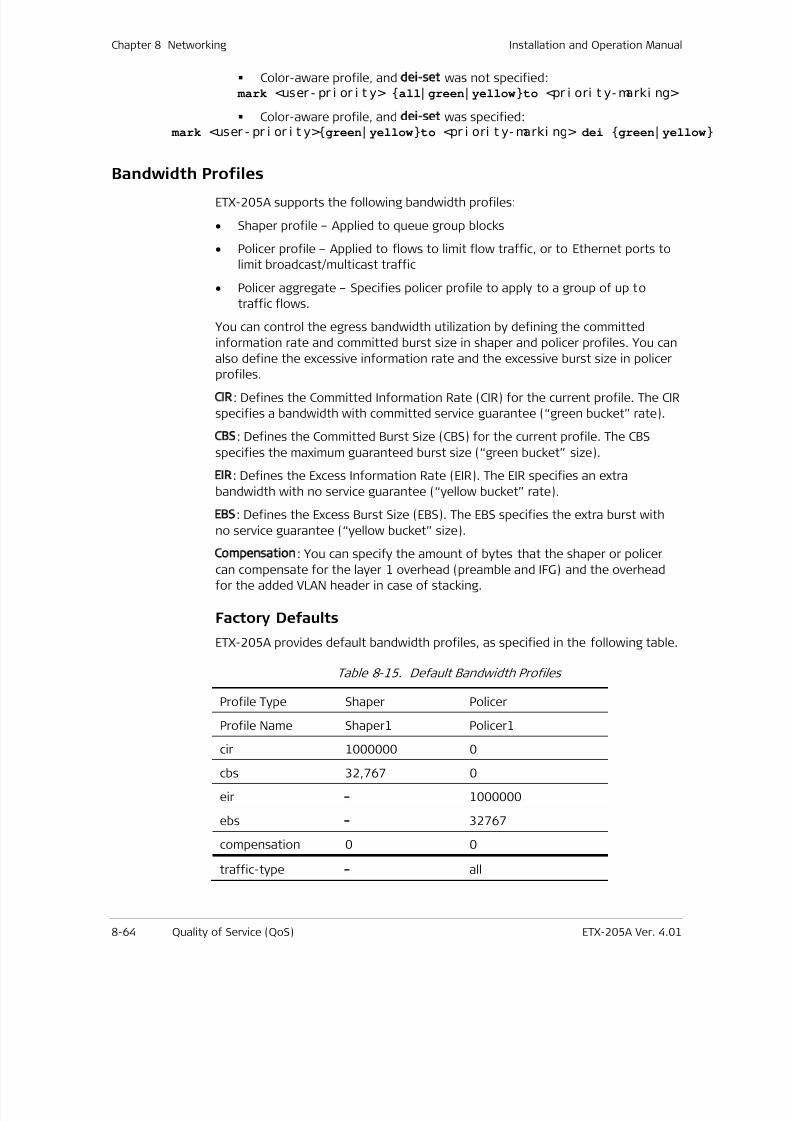
7/25/2019 Manual ETX-205A
http://slidepdf.com/reader/full/manual-etx-205a 250/409
Chapter 8 Networking Installation and Operation Manual
8-64 Quality of Service (QoS) ETX-205A Ver. 4.01
Color-aware profile, and dei-set was not specified: mark <user - pr i or i t y> all| green| yellowto <pr i ori t y- marki ng>
Color-aware profile, and dei-set was specified: mark <user - pr i or i t y>green| yellowto <pr i ori t y- marki ng> dei green| yellow
Bandwidth Profiles
ETX-205A supports the following bandwidth profiles:
• Shaper profile – Applied to queue group blocks
• Policer profile – Applied to flows to limit flow traffic, or to Ethernet ports to
limit broadcast/multicast traffic
• Policer aggregate – Specifies policer profile to apply to a group of up to
traffic flows.
You can control the egress bandwidth utilization by defining the committed
information rate and committed burst size in shaper and policer profiles. You can
also define the excessive information rate and the excessive burst size in policer
profiles.
CIR: Defines the Committed Information Rate (CIR) for the current profile. The CIR
specifies a bandwidth with committed service guarantee (“green bucket” rate).
CBS: Defines the Committed Burst Size (CBS) for the current profile. The CBS
specifies the maximum guaranteed burst size (“green bucket” size).
EIR: Defines the Excess Information Rate (EIR). The EIR specifies an extra
bandwidth with no service guarantee (“yellow bucket” rate).
EBS: Defines the Excess Burst Size (EBS). The EBS specifies the extra burst with
no service guarantee (“yellow bucket” size).
Compensation: You can specify the amount of bytes that the shaper or policercan compensate for the layer 1 overhead (preamble and IFG) and the overhead
for the added VLAN header in case of stacking.
Factory Defaults
ETX-205A provides default bandwidth profiles, as specified in the following table.
Table 8-15. Default Bandwidth Profiles
Profile Type Shaper Policer
Profile Name Shaper1 Policer1
cir 1000000 0
cbs 32,767 0
eir –
1000000
ebs – 32767
compensation 0 0
traffic-type – all
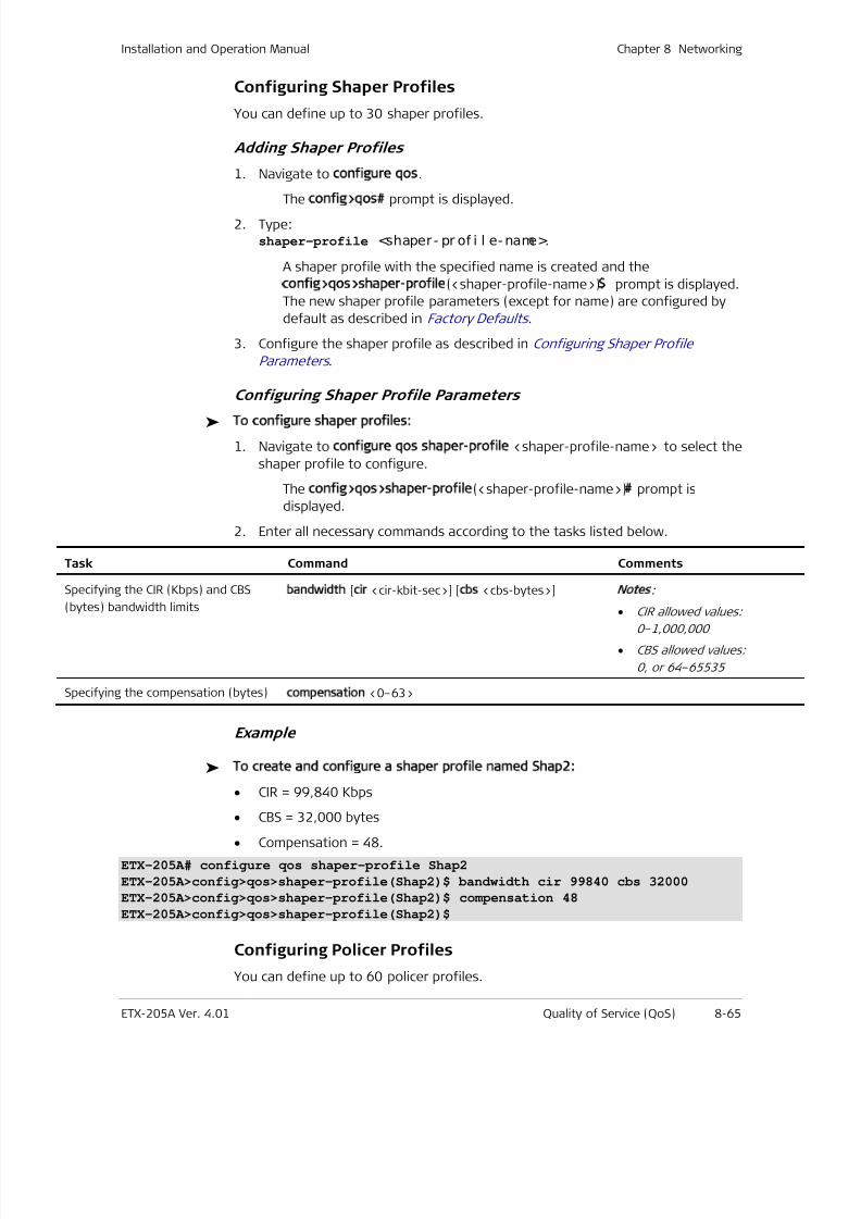
7/25/2019 Manual ETX-205A
http://slidepdf.com/reader/full/manual-etx-205a 251/409
Installation and Operation Manual Chapter 8 Networking
ETX-205A Ver. 4.01 Quality of Service (QoS) 8-65
Configuring Shaper Profiles
You can define up to 30 shaper profiles.
Adding Shaper Profiles
1. Navigate to configure qos.
The config>qos# prompt is displayed.2. Type:
shaper-profile <shaper- pr of i l e- name>.
A shaper profile with the specified name is created and the
config>qos>shaper-profile(<shaper-profile-name>)$ prompt is displayed.
The new shaper profile parameters (except for name) are configured by
default as described in Factory Defaults .
3. Configure the shaper profile as described in Configuring Shaper Profile
Parameters .
Configuring Shaper Profile Parameters
To configure shaper profiles:
1. Navigate to configure qos shaper-profile <shaper-profile-name> to select the
shaper profile to configure.
The config>qos>shaper-profile(<shaper-profile-name>)# prompt is
displayed.
2. Enter all necessary commands according to the tasks listed below.
Task Command Comments
Specifying the CIR (Kbps) and CBS
(bytes) bandwidth limits
bandwidth [cir <cir-kbit-sec>] [cbs <cbs-bytes>] Notes
:
• CIR allowed values:
0–1,000,000
• CBS allowed values:
0, or 64–65535
Specifying the compensation (bytes)compensation <0–63>
Example
To create and configure a shaper profile named Shap2:
• CIR = 99,840 Kbps
• CBS = 32,000 bytes
• Compensation = 48.
ETX-205A# configure qos shaper-profile Shap2
ETX-205A>config>qos>shaper-profile(Shap2)$ bandwidth cir 99840 cbs 32000
ETX-205A>config>qos>shaper-profile(Shap2)$ compensation 48
ETX-205A>config>qos>shaper-profile(Shap2)$
Configuring Policer Profiles
You can define up to 60 policer profiles.
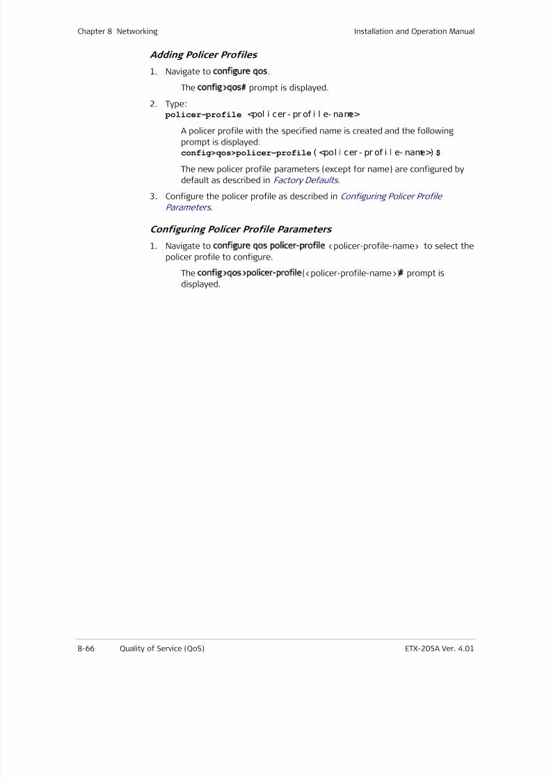
7/25/2019 Manual ETX-205A
http://slidepdf.com/reader/full/manual-etx-205a 252/409
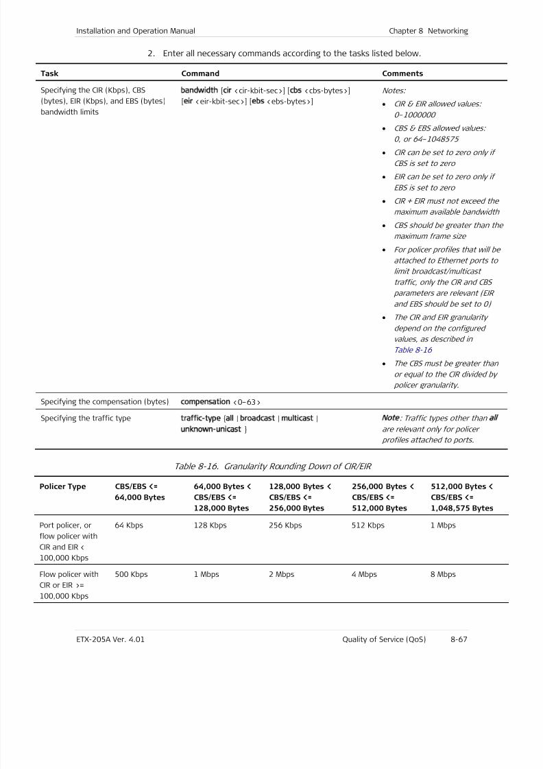
7/25/2019 Manual ETX-205A
http://slidepdf.com/reader/full/manual-etx-205a 253/409
Installation and Operation Manual Chapter 8 Networking
ETX-205A Ver. 4.01 Quality of Service (QoS) 8-67
2. Enter all necessary commands according to the tasks listed below.
Task Command Comments
Specifying the CIR (Kbps), CBS
(bytes), EIR (Kbps), and EBS (bytes)
bandwidth limits
bandwidth [cir <cir-kbit-sec>] [cbs <cbs-bytes>]
[eir <eir-kbit-sec>] [ebs <ebs-bytes>]
Notes:
• CIR & EIR allowed values:
0–1000000
• CBS & EBS allowed values:0, or 64–1048575
• CIR can be set to zero only if
CBS is set to zero
• EIR can be set to zero only if
EBS is set to zero
• CIR + EIR must not exceed the
maximum available bandwidth
• CBS should be greater than th
maximum frame size
• For policer profiles that will b
attached to Ethernet ports to
limit broadcast/multicast
traffic, only the CIR and CBS
parameters are relevant (EIR
and EBS should be set to 0)
• The CIR and EIR granularity
depend on the configured
values, as described in
Table 8-16
• The CBS must be greater than
or equal to the CIR divided by
policer granularity.
Specifying the compensation (bytes)compensation <0–63>
Specifying the traffic typetraffic-type all | broadcast | multicast |
unknown-unicast
Note
: Traffic types other thanal l
are relevant only for policer
profiles attached to ports.
Table 8-16. Granularity Rounding Down of CIR/EIR
Policer Type CBS/EBS <=
64,000 Bytes
64,000 Bytes <
CBS/EBS <=
128,000 Bytes
128,000 Bytes <
CBS/EBS <=
256,000 Bytes
256,000 Bytes <
CBS/EBS <=
512,000 Bytes
512,000 Bytes <
CBS/EBS <=
1,048,575 Bytes
Port policer, or
flow policer with
CIR and EIR <
100,000 Kbps
64 Kbps 128 Kbps 256 Kbps 512 Kbps 1 Mbps
Flow policer with
CIR or EIR >=
100,000 Kbps
500 Kbps 1 Mbps 2 Mbps 4 Mbps 8 Mbps
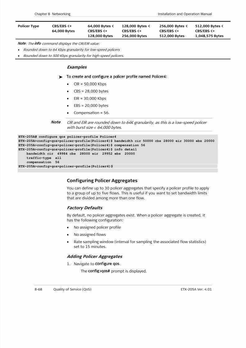
7/25/2019 Manual ETX-205A
http://slidepdf.com/reader/full/manual-etx-205a 254/409
Chapter 8 Networking Installation and Operation Manual
8-68 Quality of Service (QoS) ETX-205A Ver. 4.01
Policer Type CBS/EBS <=
64,000 Bytes
64,000 Bytes <
CBS/EBS <=
128,000 Bytes
128,000 Bytes <
CBS/EBS <=
256,000 Bytes
256,000 Bytes <
CBS/EBS <=
512,000 Bytes
512,000 Bytes <
CBS/EBS <=
1,048,575 Bytes
Note
: Theinfo
command displays the CIR/EIR value:
• Rounded down to 64 Kbps granularity for low-speed policers
• Rounded down to 500 Kbps granularity for high-speed policers.
Examples
To create and configure a policer profile named Policer4:
• CIR = 50,000 Kbps
• CBS = 28,000 bytes
• EIR = 30,000 Kbps
• EBS = 20,000 bytes
• Compensation = 56.
CIR and EIR are rounded down to 64K granularity, as this is a low-speed policer
with burst size < 64,000 bytes.
ETX-205A# configure qos policer-profile Policer4
ETX-205A>config>qos>policer-profile(Policer4)$ bandwidth cir 50000 cbs 28000 eir 30000 ebs 20000
ETX-205A>config>qos>policer-profile(Policer4)$ compensation 56
ETX-205A>config>qos>policer-profile(Policer4)$ info detail
bandwidth cir 49984 cbs 28000 eir 29952 ebs 20000
traffic-type all
compensation 56
ETX-205A>config>qos>policer-profile(Policer4)$
Configuring Policer Aggregates
You can define up to 30 policer aggregates that specify a policer profile to apply
to a group of up to five flows. This is useful if you want to set bandwidth limits
that are divided among more than one flow.
Factory Defaults
By default, no policer aggregates exist. When a policer aggregate is created, it
has the following configuration:
• No assigned policer profile
• No assigned flows
• Rate sampling window (interval for sampling the associated flow statistics)
set to 15 minutes.
Adding Policer Aggregates
1. Navigate to configure qos.
The config>qos# prompt is displayed.
Note
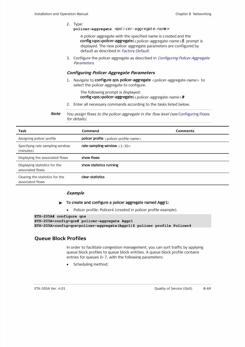
7/25/2019 Manual ETX-205A
http://slidepdf.com/reader/full/manual-etx-205a 255/409
Installation and Operation Manual Chapter 8 Networking
ETX-205A Ver. 4.01 Quality of Service (QoS) 8-69
2. Type: policer-aggregate <pol i cer - aggregat e- name>
A policer aggregate with the specified name is created and the
config>qos>policer-aggregate(<policer-aggregate-name>)$ prompt is
displayed. The new policer aggregate parameters are configured by
default as described in Factory Default .
3. Configure the policer aggregate as described in Configuring Policer AggregateParameters .
Configuring Policer Aggregate Parameters
1. Navigate to configure qos policer-aggregate <policer-aggregate-name> to
select the policer aggregate to configure.
The following prompt is displayed:
config>qos>policer-aggregate(<policer-aggregate-name>)#
2. Enter all necessary commands according to the tasks listed below.
You assign flows to the policer aggregate in the flow level (see Configuring Flowsfor details).
Task Command Comments
Assigning policer profile policer profile <policer-profile-name>
Specifying rate sampling window
(minutes)
rate-sampling-window <1–30>
Displaying the associated flows show flows
Displaying statistics for the
associated flows
show statistics running
Clearing the statistics for the
associated flows
clear-statistics
Example
To create and configure a policer aggregate named Aggr1:
• Policer profile: Policer4 (created in policer profile example).
ETX-205A# configure qos
ETX-205A>config>qos# policer-aggregate Aggr1
ETX-205A>config>qos>policer-aggregate(Aggr1)$ policer profile Policer4
Queue Block Profiles
In order to facilitate congestion management, you can sort traffic by applying
queue block profiles to queue block entities. A queue block profile contains
entries for queues 0–7, with the following parameters:
• Scheduling method:
Note
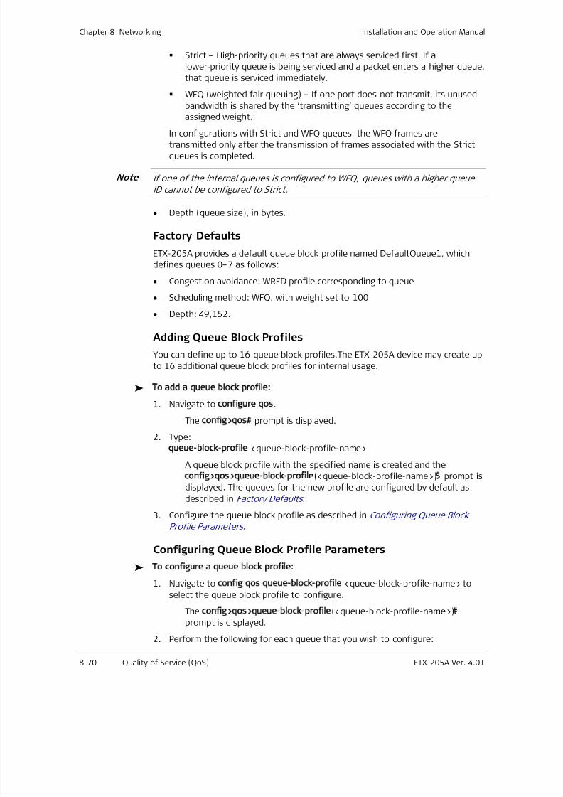
7/25/2019 Manual ETX-205A
http://slidepdf.com/reader/full/manual-etx-205a 256/409
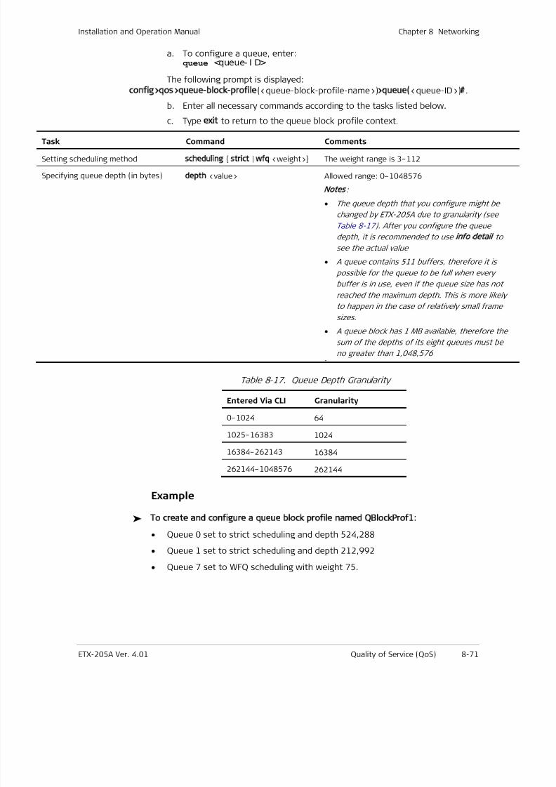
7/25/2019 Manual ETX-205A
http://slidepdf.com/reader/full/manual-etx-205a 257/409
Installation and Operation Manual Chapter 8 Networking
ETX-205A Ver. 4.01 Quality of Service (QoS) 8-71
a. To configure a queue, enter:queue <queue- I D>
The following prompt is displayed:
config>qos>queue-block-profile(<queue-block-profile-name>)>queue(<queue-ID>)#.
b. Enter all necessary commands according to the tasks listed below.
c. Type exit to return to the queue block profile context.
Task Command Comments
Setting scheduling method scheduling strict | wfq <weight> The weight range is 3–112
Specifying queue depth (in bytes) depth <value> Allowed range: 0–1048576
Notes
:
• The queue depth that you configure might be
changed by ETX-205A due to granularity (see
Table 8-17 ) . After you configure the queue
depth, it is recommended to useinfo detail
to
see the actual value
• A queue contains 511 buffers, therefore it ispossible for the queue to be full when every
buffer is in use, even if the queue size has not
reached the maximum depth. This is more likely
to happen in the case of relatively small frame
sizes.
• A queue block has 1 MB available, therefore the
sum of the depths of its eight queues must be
no greater than 1,048,576 .
Table 8-17. Queue Depth Granularity
Entered Via CLI Granularity
0–1024 64
1025–16383 1024
16384–262143 16384
262144–1048576 262144
Example
To create and configure a queue block profile named QBlockProf1:
• Queue 0 set to strict scheduling and depth 524,288
• Queue 1 set to strict scheduling and depth 212,992
• Queue 7 set to WFQ scheduling with weight 75.
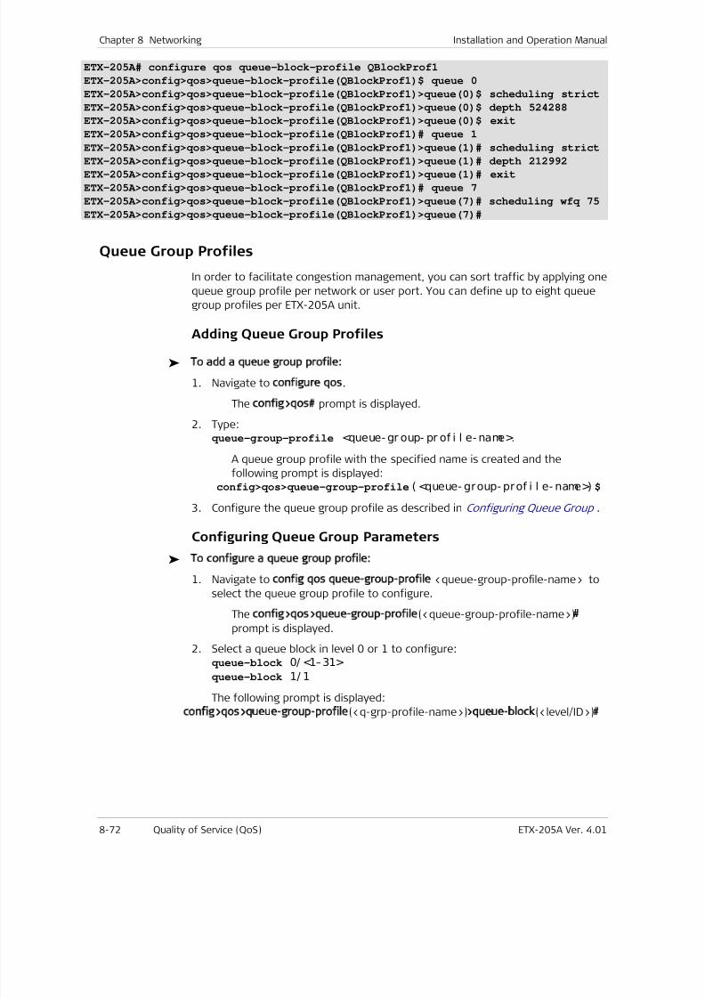
7/25/2019 Manual ETX-205A
http://slidepdf.com/reader/full/manual-etx-205a 258/409
Chapter 8 Networking Installation and Operation Manual
8-72 Quality of Service (QoS) ETX-205A Ver. 4.01
ETX-205A# configure qos queue-block-profile QBlockProf1
ETX-205A>config>qos>queue-block-profile(QBlockProf1)$ queue 0
ETX-205A>config>qos>queue-block-profile(QBlockProf1)>queue(0)$ scheduling strict
ETX-205A>config>qos>queue-block-profile(QBlockProf1)>queue(0)$ depth 524288
ETX-205A>config>qos>queue-block-profile(QBlockProf1)>queue(0)$ exit
ETX-205A>config>qos>queue-block-profile(QBlockProf1)# queue 1
ETX-205A>config>qos>queue-block-profile(QBlockProf1)>queue(1)# scheduling strict
ETX-205A>config>qos>queue-block-profile(QBlockProf1)>queue(1)# depth 212992ETX-205A>config>qos>queue-block-profile(QBlockProf1)>queue(1)# exit
ETX-205A>config>qos>queue-block-profile(QBlockProf1)# queue 7
ETX-205A>config>qos>queue-block-profile(QBlockProf1)>queue(7)# scheduling wfq 75
ETX-205A>config>qos>queue-block-profile(QBlockProf1)>queue(7)#
Queue Group Profiles
In order to facilitate congestion management, you can sort traffic by applying one
queue group profile per network or user port. You can define up to eight queue
group profiles per ETX-205A unit.
Adding Queue Group Profiles
To add a queue group profile:
1. Navigate to configure qos.
The config>qos# prompt is displayed.
2. Type:queue-group-profile <queue- gr oup- pr of i l e- name>.
A queue group profile with the specified name is created and the
following prompt is displayed:config>qos>queue-group-profile( <queue- group- prof i l e- name>) $
3. Configure the queue group profile as described in Configuring Queue Group .
Configuring Queue Group Parameters
To configure a queue group profile:
1. Navigate to config qos queue-group-profile <queue-group-profile-name> to
select the queue group profile to configure.
The config>qos>queue-group-profile(<queue-group-profile-name>)#
prompt is displayed.
2. Select a queue block in level 0 or 1 to configure:
queue-block 0/ <1–31>queue-block 1/ 1
The following prompt is displayed:
config>qos>queue-group-profile(<q-grp-profile-name>)>queue-block(<level/ID>)#
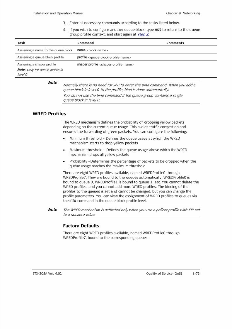
7/25/2019 Manual ETX-205A
http://slidepdf.com/reader/full/manual-etx-205a 259/409
Installation and Operation Manual Chapter 8 Networking
ETX-205A Ver. 4.01 Quality of Service (QoS) 8-73
3. Enter all necessary commands according to the tasks listed below.
4. If you wish to configure another queue block, type exit to return to the queue
group profile context, and start again at step 2 .
Task Command Comments
Assigning a name to the queue block name <block-name>
Assigning a queue block profileprofile <queue-block-profile-name>
Assigning a shaper profile
Note: Only for queue blocks in
level 0
shaper profile <shaper-profile-name>
Normally there is no need for you to enter the bind command. When you add a
queue block in level 0 to the profile, bind is done automatically.
You cannot use the bind command if the queue group contains a single
queue block in level 0.
WRED Profiles
The WRED mechanism defines the probability of dropping yellow packets
depending on the current queue usage. This avoids traffic congestion and
ensures the forwarding of green packets. You can configure the following:
• Minimum threshold – Defines the queue usage at which the WRED
mechanism starts to drop yellow packets
• Maximum threshold – Defines the queue usage above which the WRED
mechanism drops all yellow packets
• Probability –Determines the percentage of packets to be dropped when the
queue usage reaches the maximum threshold
There are eight WRED profiles available, named WREDProfile0 through
WREDProfile7. They are bound to the queues automatically: WREDProfile0 is
bound to queue 0, WREDProfile1 is bound to queue 1, etc. You cannot delete the
WRED profiles, and you cannot add more WRED profiles. The binding of the
profiles to the queues is set and cannot be changed, but you can change the
profile parameters. You can view the assignment of WRED profiles to queues via
the info command in the queue block profile level.
The WRED mechanism is activated only when you use a policer profile with EIR set
to a nonzero value.
Factory Defaults
There are eight WRED profiles available, named WREDProfile0 through
WREDProfile7, bound to the corresponding queues.
Note
Note

7/25/2019 Manual ETX-205A
http://slidepdf.com/reader/full/manual-etx-205a 260/409
Chapter 8 Networking Installation and Operation Manual
8-74 Router ETX-205A Ver. 4.01
Configuring WRED Profiles
To configure WRED profiles:
1. Navigate to configure qos and type wred-profile WREDProfile<n> where n is 0
through 7.
The config>qos>wred-profile(WREDProfile<n>)# prompt is displayed.
2. Enter:color yellow min <mi n- t hr eshol d> max <max- t hreshol d>
[ probability <max- probabi l i t y>]
min-threshold –Queue usage minimum threshold in percentage, 0–100
max-threshold –Queue usage maximum threshold in percentage, 0–100
max-probability – Percentage of packets to be dropped when the queue
usage reaches the maximimum limit.
You can configure the parameters for the color yellow only.
Example
To configure WRED profile 4:
• Minimum threshold 64
• Maximum threshold 100
• Probability 50.
ETX-205A# configure qos wred-profile WREDProfile4
ETX-205A>config>qos>wred-profile(WREDProfile4)# color yellow min 64 max 100 probability 50
ETX-205A>config>qos>wred-profile(WREDProfile4)# info detail
color yellow min 64 max 100 probability 50
ETX-205A>config>qos>wred-profile(WREDProfile4)#
8.5 Router
The router in ETX-205A is used to interconnect internal Layer 3 support modules
such as management and 1588v2 (recovered clock). Any flow related to
management or timing must be via an SVI that is bound to a router interface.
• You can configure up to eight router interfaces
• In order to enable management, you must configure a router interface
enabled for management access, assign it an IP address, and bind it to an SVI
for which management flows have been defined. Refer to the Quick Start
Guide f or an example of management configuration.
Notes
Note
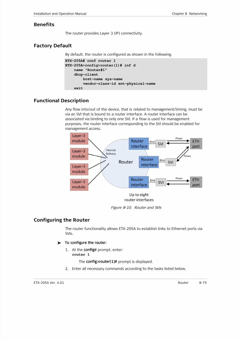
7/25/2019 Manual ETX-205A
http://slidepdf.com/reader/full/manual-etx-205a 261/409
Installation and Operation Manual Chapter 8 Networking
ETX-205A Ver. 4.01 Router 8-75
Benefits
The router provides Layer-3 (IP) connectivity.
Factory Default
By default, the router is configured as shown in the following.
ETX-205A# conf router 1
ETX-205A>config>router(1)# inf d
name "Router#1"
dhcp-client
host-name sys-name
vendor-class-id ent-physical-name
exit
Functional Description
Any flow into/out of the device, that is related to management/timing, must be
via an SVI that is bound to a router interface. A router interface can beassociated via binding to only one SVI. If a flow is used for management
purposes, the router interface corresponding to the SVI should be enabled for
management access.
Figure 8-10. Router and SVIs
Configuring the Router
The router functionality allows ETX-205A to establish links to Ethernet ports via
SVIs.
To configure the router:
1. At the config# prompt, enter:router 1
The config>router(1)# prompt is displayed.
2. Enter all necessary commands according to the tasks listed below.
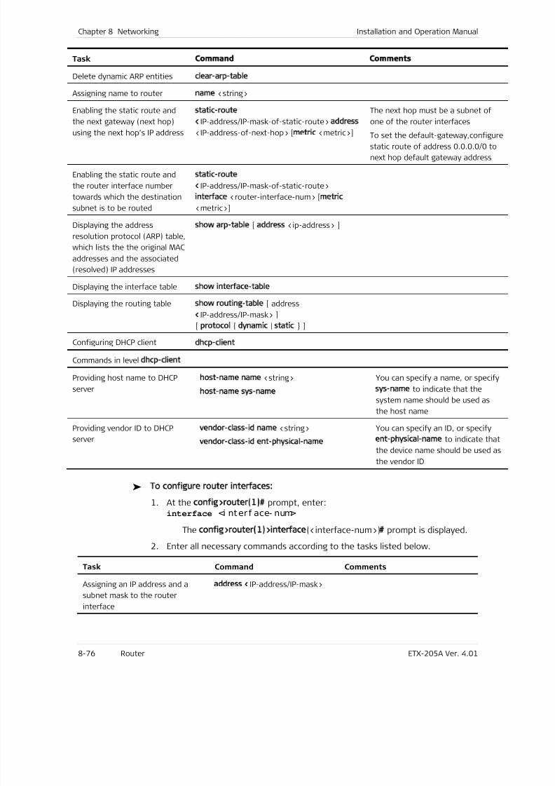
7/25/2019 Manual ETX-205A
http://slidepdf.com/reader/full/manual-etx-205a 262/409
Chapter 8 Networking Installation and Operation Manual
8-76 Router ETX-205A Ver. 4.01
Task ommand omments
Delete dynamic ARP entities clear-arp-table
Assigning name to router name <string>
Enabling the static route and
the next gateway (next hop)
using the next hop’s IP address
static-route
<IP-address/IP-mask-of-static-route> address
<IP-address-of-next-hop> [metric <metric>]
The next hop must be a subnet of
one of the router interfaces
To set the default-gateway,configure
static route of address 0.0.0.0/0 to
next hop default gateway address
Enabling the static route and
the router interface number
towards which the destination
subnet is to be routed
static-route
<IP-address/IP-mask-of-static-route>
interface <router-interface-num> [metric
<metric>]
Displaying the address
resolution protocol (ARP) table,
which lists the the original MAC
addresses and the associated(resolved) IP addresses
show arp-table [ address <ip-address> ]
Displaying the interface table show interface-table
Displaying the routing table show routing-table [ address
<IP-address/IP-mask> ]
[ protocol dynamic | static ]
Configuring DHCP clientdhcp-client
Commands in level dhcp-client
Providing host name to DHCP
server
host-name name <string>
host-name sys-name
You can specify a name, or specify
sys-name to indicate that thesystem name should be used as
the host name
Providing vendor ID to DHCP
server
vendor-class-id name <string>
vendor-class-id ent-physical-name
You can specify an ID, or specify
ent-physical-name to indicate that
the device name should be used as
the vendor ID
To configure router interfaces:
1. At the config>router(1)# prompt, enter:interface <i nter f ace- num>
The config>router(1)>interface(<interface-num>)# prompt is displayed.
2. Enter all necessary commands according to the tasks listed below.
Task Command Comments
Assigning an IP address and a
subnet mask to the router
interface
address <IP-address/IP-mask>
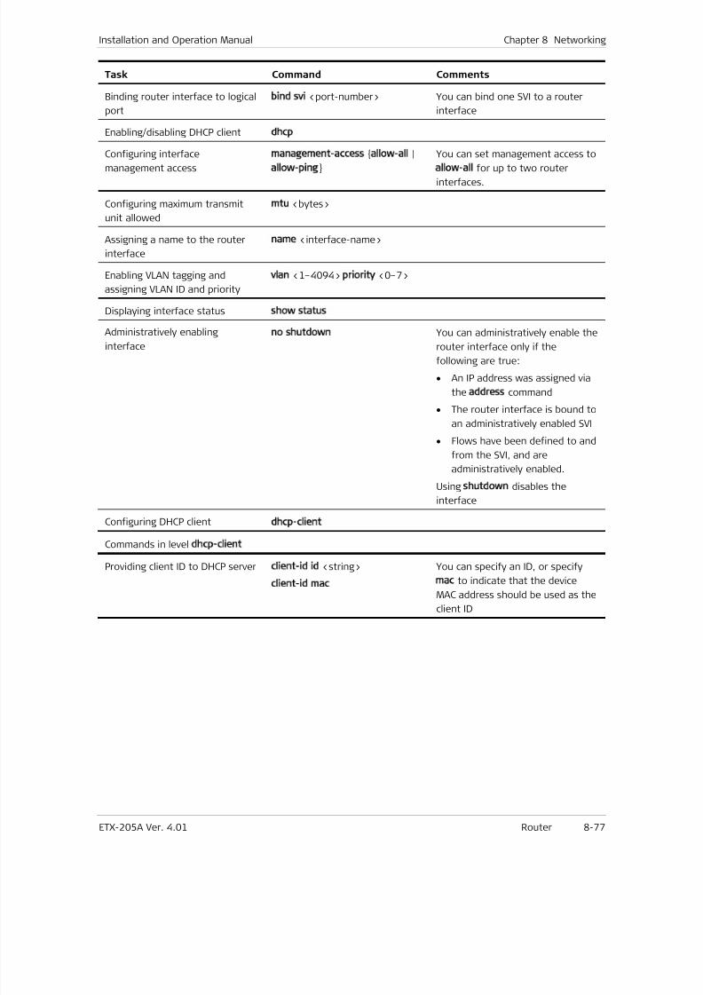
7/25/2019 Manual ETX-205A
http://slidepdf.com/reader/full/manual-etx-205a 263/409
Installation and Operation Manual Chapter 8 Networking
ETX-205A Ver. 4.01 Router 8-77
Task Command Comments
Binding router interface to logical
port
bind svi <port-number> You can bind one SVI to a router
interface
Enabling/disabling DHCP client dhcp
Configuring interface
management access
management-access allow-all |
allow-ping
You can set management access to
allow-all for up to two router
interfaces.
Configuring maximum transmit
unit allowed
mtu <bytes>
Assigning a name to the router
interface
name <interface-name>
Enabling VLAN tagging and
assigning VLAN ID and priority
vlan <1–4094> priority <0–7>
Displaying interface status show status
Administratively enablinginterface
no shutdown You can administratively enable therouter interface only if the
following are true:
• An IP address was assigned via
the address command
• The router interface is bound to
an administratively enabled SVI
• Flows have been defined to and
from the SVI, and are
administratively enabled.
Using shutdown disables the
interface
Configuring DHCP clientdhcp-client
Commands in level dhcp-client
Providing client ID to DHCP server client-id id <string>
client-id mac
You can specify an ID, or specify
mac to indicate that the device
MAC address should be used as the
client ID

7/25/2019 Manual ETX-205A
http://slidepdf.com/reader/full/manual-etx-205a 264/409
7/25/2019 Manual ETX-205A
http://slidepdf.com/reader/full/manual-etx-205a 265/409
ETX-205A Ver. 4.01 Clock Selection 9-1
Chapter 9
Timing and
SynchronizationThis chapter describes timing and synchronization features:
• Clock Selection
• Date and Time .
9.1 Clock Selection
Standards
ITU-T G.8261/G.8262
Benefits
The clock selection provides synchronization over packet transport networks.
Functional Description
You can configure a slave (recovered) clock that complies with the IEEE-1588
Precision Time Protocol (PTP). You need to configure the clock domain before
configuring the recovered clock.
ETX-205A supports one clock domain with up to two clock sources. The sources
can be network/user Ethernet ports or the station clock. The timing subsystem
automatically selects the best timing source to use for synchronization.
Clock Domain
The domain parameters include the synchronization network type and the timing
quality level.
The synchronization network type identifies the type of synchronization network
connections and the synchronization level. Each synchronization network
connection is provided by one or more synchronization link connections, each
supported by a synchronized PDH trail, SDH multiplex section trail, or 802.3
physical media trail.
The synchronization network types are:
i. Option I (Europe)
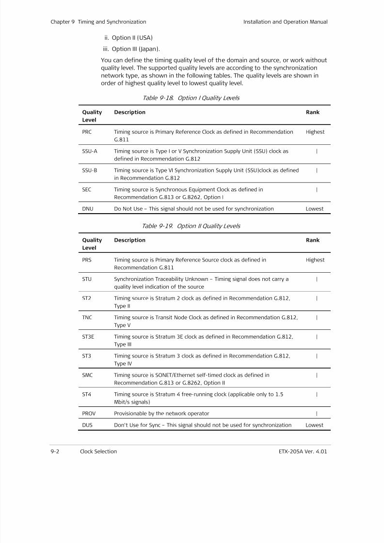
7/25/2019 Manual ETX-205A
http://slidepdf.com/reader/full/manual-etx-205a 266/409
Chapter 9 Timing and Synchronization Installation and Operation Manual
9-2 Clock Selection ETX-205A Ver. 4.01
ii. Option II (USA)
iii. Option III (Japan).
You can define the timing quality level of the domain and source, or work without
quality level. The supported quality levels are according to the synchronization
network type, as shown in the following tables. The quality levels are shown in
order of highest quality level to lowest quality level.
Table 9-18. Option I Quality Levels
Quality
Level
Description Rank
PRC Timing source is Primary Reference Clock as defined in Recommendation
G.811
Highest
SSU-A Timing source is Type I or V Synchronization Supply Unit (SSU) clock as
defined in Recommendation G.812
|
SSU-B Timing source is Type VI Synchronization Supply Unit (SSU)clock as defined
in Recommendation G.812
|
SEC Timing source is Synchronous Equipment Clock as defined in
Recommendation G.813 or G.8262, Option I
|
DNU Do Not Use – This signal should not be used for synchronization Lowest
Table 9-19. Option II Quality Levels
Quality
Level
Description Rank
PRS Timing source is Primary Reference Source clock as defined in
Recommendation G.811
Highest
STU Synchronization Traceability Unknown – Timing signal does not carry a
quality level indication of the source
|
ST2 Timing source is Stratum 2 clock as defined in Recommendation G.812,
Type II
|
TNC Timing source is Transit Node Clock as defined in Recommendation G.812,
Type V
|
ST3E Timing source is Stratum 3E clock as defined in Recommendation G.812,
Type III
|
ST3 Timing source is Stratum 3 clock as defined in Recommendation G.812,
Type IV
|
SMC Timing source is SONET/Ethernet self-timed clock as defined in
Recommendation G.813 or G.8262, Option II
|
ST4 Timing source is Stratum 4 free-running clock (applicable only to 1.5
Mbit/s signals)
|
PROV Provisionable by the network operator |
DUS Don't Use for Sync – This signal should not be used for synchronization Lowest
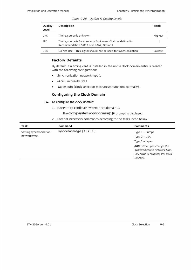
7/25/2019 Manual ETX-205A
http://slidepdf.com/reader/full/manual-etx-205a 267/409
Installation and Operation Manual Chapter 9 Timing and Synchronization
ETX-205A Ver. 4.01 Clock Selection 9-3
Table 9-20. Option III Quality Levels
Quality
Level
Description Rank
UNK Timing source is unknown Highest
SEC Timing source is Synchronous Equipment Clock as defined in
Recommendation G.813 or G.8262, Option I
|
DNU Do Not Use – This signal should not be used for synchronization Lowest
Factory Defaults
By default, if a timing card is installed in the unit a clock domain entry is created
with the following configuration:
• Synchronization network type 1
• Minimum quality DNU
• Mode auto (clock selection mechanism functions normally).
Configuring the Clock Domain
To configure the clock domain:
1. Navigate to configure system clock domain 1.
The config>system>clock>domain(1)# prompt is displayed.
2. Enter all necessary commands according to the tasks listed below.
Task Command Comments
Setting synchronization
network type
sync-network-type 1 | 2 | 3 Type 1 – Europe
Type 2 – USA
Type 3 – Japan
Note: When you change the
synchronization network type,
you have to redefine the clock
sources.
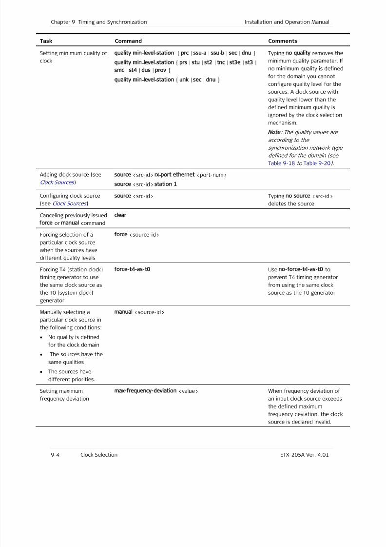
7/25/2019 Manual ETX-205A
http://slidepdf.com/reader/full/manual-etx-205a 268/409
Chapter 9 Timing and Synchronization Installation and Operation Manual
9-4 Clock Selection ETX-205A Ver. 4.01
Task Command Comments
Setting minimum quality of
clock
quality min-level-station prc | ssu-a | ssu-b | sec | dnu
quality min-level-station prs | stu | st2 | tnc | st3e | st3 |
smc | st4 | dus | prov
quality min-level-station unk | sec | dnu
Typing no quality removes the
minimum quality parameter. If
no minimum quality is defined
for the domain you cannot
configure quality level for the
sources. A clock source withquality level lower than the
defined minimum quality is
ignored by the clock selection
mechanism.
Note: The quality values are
according to the
synchronization network type
defined for the domain (see
Table 9-18 to Table 9-20) .
Adding clock source (see
Clock Sources )
source <src-id> rx-port ethernet <port-num>
source <src-id> station 1
Configuring clock source
(see Clock Sources )
source <src-id> Typing no source <src-id>
deletes the source
Canceling previously issued
force or manual command
clear
Forcing selection of a
particular clock source
when the sources have
different quality levels
force <source-id>
Forcing T4 (station clock)
timing generator to use
the same clock source as
the T0 (system clock)
generator
force-t4-as-t0 Use no-force-t4-as-t0 to
prevent T4 timing generator
from using the same clock
source as the T0 generator
Manually selecting a
particular clock source in
the following conditions:
• No quality is defined
for the clock domain
• The sources have the
same qualities• The sources have
different priorities.
manual <source-id>
Setting maximum
frequency deviation
max-frequency-deviation <value> When frequency deviation of
an input clock source exceeds
the defined maximum
frequency deviation, the clock
source is declared invalid.
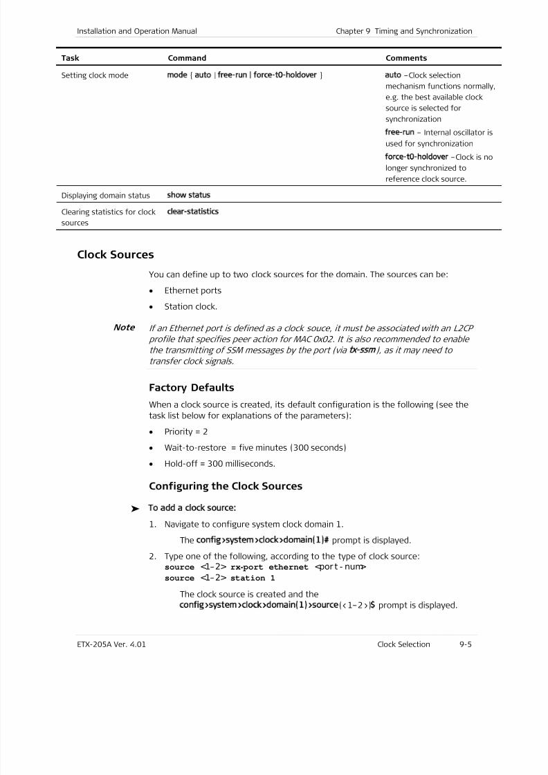
7/25/2019 Manual ETX-205A
http://slidepdf.com/reader/full/manual-etx-205a 269/409
Installation and Operation Manual Chapter 9 Timing and Synchronization
ETX-205A Ver. 4.01 Clock Selection 9-5
Task Command Comments
Setting clock mode mode auto | free-run | force-t0-holdover auto –Clock selection
mechanism functions normally,
e.g. the best available clock
source is selected for
synchronization
free-run – Internal oscillator is
used for synchronization
force-t0-holdover –Clock is no
longer synchronized to
reference clock source.
Displaying domain status show status
Clearing statistics for clock
sources
clear-statistics
Clock SourcesYou can define up to two clock sources for the domain. The sources can be:
• Ethernet ports
• Station clock.
If an Ethernet port is defined as a clock souce, it must be associated with an L2CP
profile that specifies peer action for MAC 0x02. It is also recommended to enable
the transmitting of SSM messages by the port (via tx ssm), as it may need to
transfer clock signals.
Factory Defaults
When a clock source is created, its default configuration is the following (see the
task list below for explanations of the parameters):
• Priority = 2
• Wait-to-restore = five minutes (300 seconds)
• Hold-off = 300 milliseconds.
Configuring the Clock Sources
To add a clock source:
1. Navigate to configure system clock domain 1.
The config>system>clock>domain(1)# prompt is displayed.
2. Type one of the following, according to the type of clock source:source <1–2> rx- port ethernet <por t - num>
source <1–2> station 1
The clock source is created and the
config>system>clock>domain(1)>source(<1–2>)$ prompt is displayed.
Note
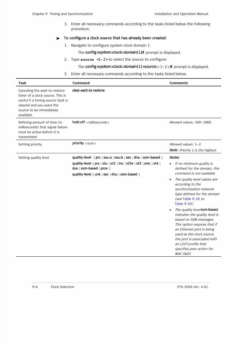
7/25/2019 Manual ETX-205A
http://slidepdf.com/reader/full/manual-etx-205a 270/409
Chapter 9 Timing and Synchronization Installation and Operation Manual
9-6 Clock Selection ETX-205A Ver. 4.01
3. Enter all necessary commands according to the tasks listed below the following
procedure.
To configure a clock source that has already been created:
1. Navigate to configure system clock domain 1.
The config>system>clock>domain(1)# prompt is displayed.
2. Type source <1–2> to select the source to configure.
The config>system>clock>domain(1)>source(<1–2>)# prompt is displayed.
3. Enter all necessary commands according to the tasks listed below.
Task Command Comments
Canceling the wait-to-restore
timer of a clock source. This is
useful if a timing source fault is
cleared and you want the
source to be immediately
available.
clear-wait-to-restore
Defining amount of time (in
milliseconds) that signal failure
must be active before it is
transmitted
hold-off <milliseconds> Allowed values: 300–1800
Setting priority priority <num> Allowed values: 1–2
Note
: Priority 1 is the highest.
Setting quality level quality-level prc | ssu-a | ssu-b | sec | dnu | ssm-based
quality-level prs | stu | st2 | tnc | st3e | st3 | smc | st4 |
dus | ssm-based | prov
quality-level unk | sec | dnu | ssm-based
Notes
:
• If no minimum quality is
defined for the domain, this
command is not available
• The quality level values are
according to the
synchronization network
type defined for the domain
(see Table 9-18 to
Table 9-20)
• The quality level ssm-based
indicates the quality level is
based on SSM messages.
This option requires that if
an Ethernet port is beingused as the clock source,
the port is associated with
an L2CP profile that
specifies peer action for
MAC 0x02.
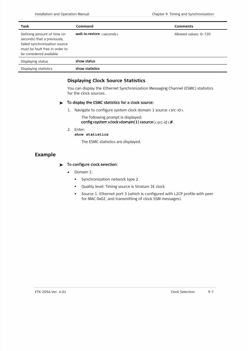
7/25/2019 Manual ETX-205A
http://slidepdf.com/reader/full/manual-etx-205a 271/409
Installation and Operation Manual Chapter 9 Timing and Synchronization
ETX-205A Ver. 4.01 Clock Selection 9-7
Task Command Comments
Defining amount of time (in
seconds) that a previously
failed synchronization source
must be fault free in order to
be considered available
wait-to-restore <seconds> Allowed values: 0–720
Displaying status show status
Displaying statisticsshow statistics
Displaying Clock Source Statistics
You can display the Ethernet Synchronization Messaging Channel (ESMC) statistics
for the clock sources.
To display the ESMC statistics for a clock source:
1. Navigate to configure system clock domain 1 source <src-id>.
The following prompt is displayed:config>system>clock>domain(1)>source(<src-id>)#.
2. Enter:show statistics
The ESMC statistics are displayed.
Example
To configure clock selection:
• Domain 1:
Synchronization network type 2
Quality level: Timing source is Stratum 3E clock
Source 1: Ethernet port 3 (which is configured with L2CP profile with peer
for MAC 0x02, and transmitting of clock SSM messages).
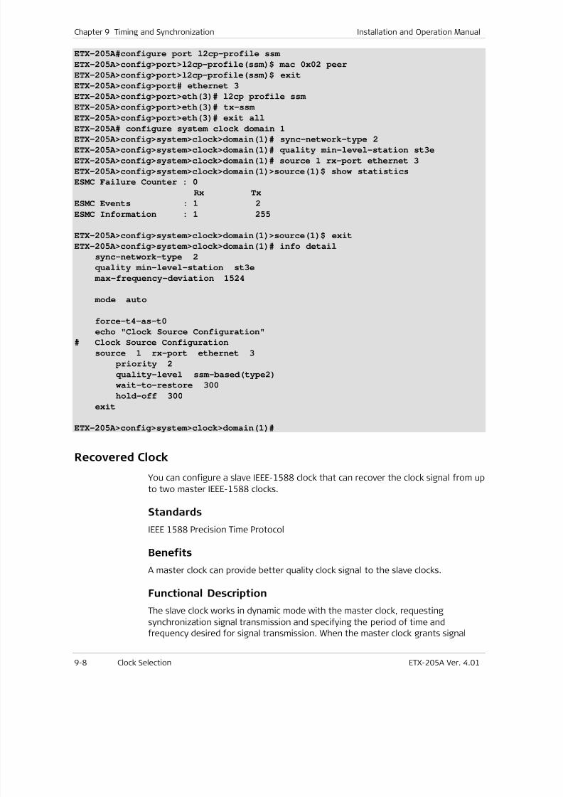
7/25/2019 Manual ETX-205A
http://slidepdf.com/reader/full/manual-etx-205a 272/409
Chapter 9 Timing and Synchronization Installation and Operation Manual
9-8 Clock Selection ETX-205A Ver. 4.01
ETX-205A#configure port l2cp-profile ssm
ETX-205A>config>port>l2cp-profile(ssm)$ mac 0x02 peer
ETX-205A>config>port>l2cp-profile(ssm)$ exit
ETX-205A>config>port# ethernet 3
ETX-205A>config>port>eth(3)# l2cp profile ssm
ETX-205A>config>port>eth(3)# tx-ssm
ETX-205A>config>port>eth(3)# exit all
ETX-205A# configure system clock domain 1ETX-205A>config>system>clock>domain(1)# sync-network-type 2
ETX-205A>config>system>clock>domain(1)# quality min-level-station st3e
ETX-205A>config>system>clock>domain(1)# source 1 rx-port ethernet 3
ETX-205A>config>system>clock>domain(1)>source(1)$ show statistics
ESMC Failure Counter : 0
Rx Tx
ESMC Events : 1 2
ESMC Information : 1 255
ETX-205A>config>system>clock>domain(1)>source(1)$ exit
ETX-205A>config>system>clock>domain(1)# info detail
sync-network-type 2
quality min-level-station st3e max-frequency-deviation 1524
mode auto
force-t4-as-t0
echo "Clock Source Configuration"
# Clock Source Configuration
source 1 rx-port ethernet 3
priority 2
quality-level ssm-based(type2)
wait-to-restore 300
hold-off 300exit
ETX-205A>config>system>clock>domain(1)#
Recovered Clock
You can configure a slave IEEE-1588 clock that can recover the clock signal from up
to two master IEEE-1588 clocks.
Standards
IEEE 1588 Precision Time Protocol
Benefits
A master clock can provide better quality clock signal to the slave clocks.
Functional Description
The slave clock works in dynamic mode with the master clock, requesting
synchronization signal transmission and specifying the period of time and
frequency desired for signal transmission. When the master clock grants signal
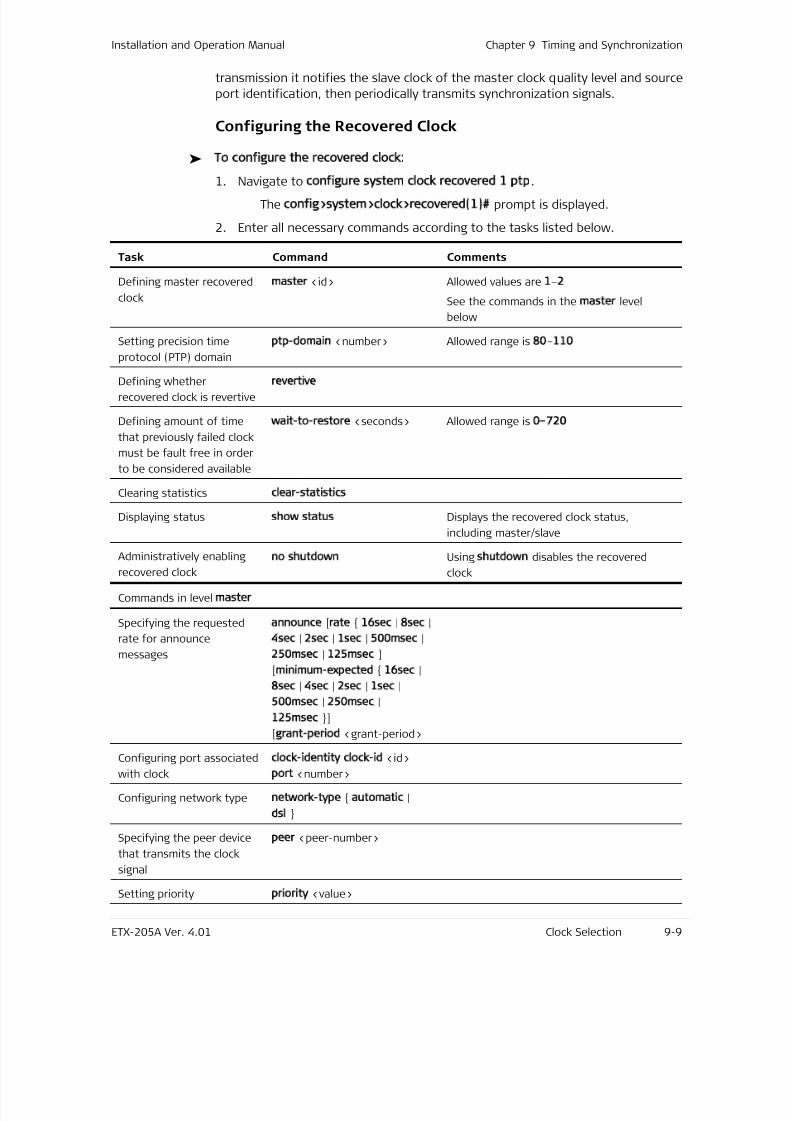
7/25/2019 Manual ETX-205A
http://slidepdf.com/reader/full/manual-etx-205a 273/409
Installation and Operation Manual Chapter 9 Timing and Synchronization
ETX-205A Ver. 4.01 Clock Selection 9-9
transmission it notifies the slave clock of the master clock quality level and source
port identification, then periodically transmits synchronization signals.
Configuring the Recovered Clock
To configure the recovered clock:
1. Navigate to configure system clock recovered 1 ptp.The config>system>clock>recovered(1)# prompt is displayed.
2. Enter all necessary commands according to the tasks listed below.
Task Command Comments
Defining master recovered
clock
master <id> Allowed values are 1–2
See the commands in the master level
below
Setting precision time
protocol (PTP) domain
ptp-domain <number> Allowed range is 80–110
Defining whether
recovered clock is revertive
revertive
Defining amount of time
that previously failed clock
must be fault free in order
to be considered available
wait-to-restore <seconds> Allowed range is 0–720
Clearing statistics clear-statistics
Displaying status show status Displays the recovered clock status,
including master/slave
Administratively enablingrecovered clock
no shutdown Using shutdown disables the recoveredclock
Commands in level master
Specifying the requested
rate for announce
messages
announce [rate 16sec | 8sec |
4sec | 2sec | 1sec | 500msec |
250msec | 125msec
[minimum-expected 16sec |
8sec | 4sec | 2sec | 1sec |
500msec | 250msec |
125msec ]
[grant-period <grant-period>
Configuring port associated
with clock
clock-identity clock-id <id>
port <number>
Configuring network type network-type automatic |
dsl
Specifying the peer device
that transmits the clock
signal
peer <peer-number>
Setting priority priority <value>
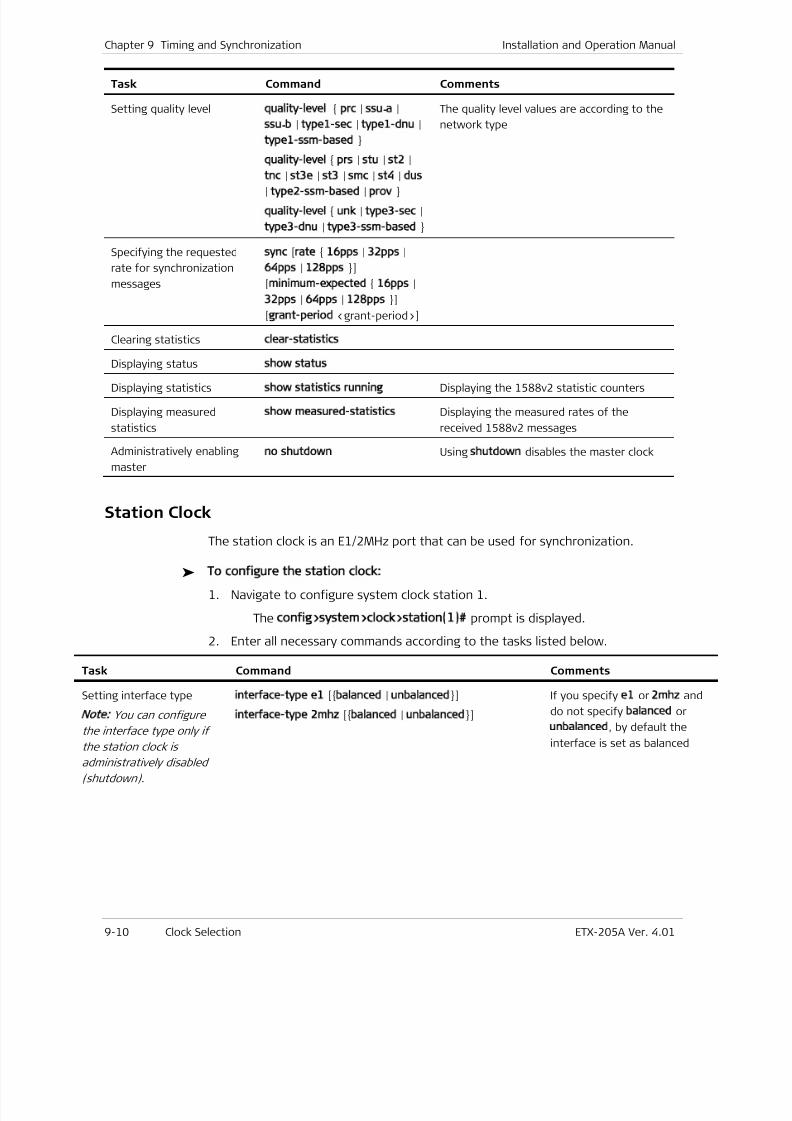
7/25/2019 Manual ETX-205A
http://slidepdf.com/reader/full/manual-etx-205a 274/409
Chapter 9 Timing and Synchronization Installation and Operation Manual
9-10 Clock Selection ETX-205A Ver. 4.01
Task Command Comments
Setting quality level quality-level prc | ssu-a |
ssu-b | type1-sec | type1-dnu |
type1-ssm-based
quality-level prs | stu | st2 |
tnc | st3e | st3 | smc | st4 | dus
| type2-ssm-based | prov
quality-level unk | type3-sec |
type3-dnu | type3-ssm-based
The quality level values are according to the
network type
Specifying the requested
rate for synchronization
messages
sync [rate 16pps | 32pps |
64pps | 128pps ]
[minimum-expected 16pps |
32pps | 64pps | 128pps ]
[grant-period <grant-period>]
Clearing statistics clear-statistics
Displaying status show status
Displaying statistics show statistics running Displaying the 1588v2 statistic counters
Displaying measured
statistics
show measured-statistics Displaying the measured rates of the
received 1588v2 messages
Administratively enabling
master
no shutdown Using shutdown disables the master clock
Station Clock
The station clock is an E1/2MHz port that can be used for synchronization.
To configure the station clock:
1. Navigate to configure system clock station 1.
The config>system>clock>station(1)# prompt is displayed.
2. Enter all necessary commands according to the tasks listed below.
Task Command Comments
Setting interface type
Note:
You can configure
the interface type only if
the station clock isadministratively disabled
(shutdown).
interface-type e1 [balanced | unbalanced]
interface-type 2mhz [balanced | unbalanced]
If you specify e1 or 2mhz and
do not specify balanced or
unbalanced, by default the
interface is set as balanced
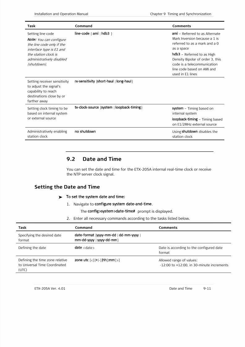
7/25/2019 Manual ETX-205A
http://slidepdf.com/reader/full/manual-etx-205a 275/409
Installation and Operation Manual Chapter 9 Timing and Synchronization
ETX-205A Ver. 4.01 Date and Time 9-11
Task Command Comments
Setting line code
Note: You can configure
the line code only if the
interface type is E1 and
the station clock is
administratively disabled
(shutdown).
line-code ami | hdb3 ami – Referred to as Alternate
Mark Inversion because a 1 is
referred to as a mark and a 0
as a space
hdb3 – Referred to as High
Density Bipolar of order 3, this
code is a telecommunication
line code based on AMI and
used in E1 lines
Setting receiver sensitivity
to adjust the signal’s
capability to reach
destinations close by or
farther away
rx-sensitivity short-haul | long-haul
Setting clock timing to be
based on internal system
or external source
tx-clock-source system | loopback-timing system – Timing based on
internal system
loopback-timing – Timing based
on E1/2MHz external source
Administratively enabling
station clock
no shutdown Using shutdown disables the
station clock
9.2 Date and Time
You can set the date and time for the ETX-205A internal real-time clock or receive
the NTP server clock signal.
Setting the Date and Time
To set the system date and time:
1. Navigate to configure system date-and-time.
The config>system>date-time# prompt is displayed.
2. Enter all necessary commands according to the tasks listed below.
Task Command Comments
Specifying the desired date
format
date-format yyyy-mm-dd | dd-mm-yyyy |
mm-dd-yyyy | yyyy-dd-mm
Defining the date date <date> Date is according to the configured date
format
Defining the time zone relative
to Universal Time Coordinated
(UTC)
zone utc [<[+|-]hh[:mm]>] Allowed range of values:
-12:00 to +12:00, in 30-minute increme
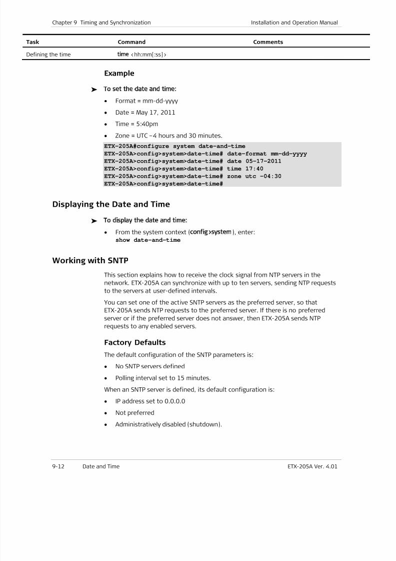
7/25/2019 Manual ETX-205A
http://slidepdf.com/reader/full/manual-etx-205a 276/409
Chapter 9 Timing and Synchronization Installation and Operation Manual
9-12 Date and Time ETX-205A Ver. 4.01
Task Command Comments
Defining the time time <hh:mm[:ss]>
Example
To set the date and time:
• Format = mm-dd-yyyy
• Date = May 17, 2011
• Time = 5:40pm
• Zone = UTC –4 hours and 30 minutes.
ETX-205A#configure system date-and-time
ETX-205A>config>system>date-time# date-format mm-dd-yyyy
ETX-205A>config>system>date-time# date 05-17-2011
ETX-205A>config>system>date-time# time 17:40
ETX-205A>config>system>date-time# zone utc -04:30
ETX-205A>config>system>date-time#
Displaying the Date and Time
To display the date and time:
• From the system context (config>system), enter:show date-and-time
Working with SNTP
This section explains how to receive the clock signal from NTP servers in the
network. ETX-205A can synchronize with up to ten servers, sending NTP requests
to the servers at user-defined intervals.
You can set one of the active SNTP servers as the preferred server, so that
ETX-205A sends NTP requests to the preferred server. If there is no preferred
server or if the preferred server does not answer, then ETX-205A sends NTP
requests to any enabled servers.
Factory Defaults
The default configuration of the SNTP parameters is:
• No SNTP servers defined
• Polling interval set to 15 minutes.
When an SNTP server is defined, its default configuration is:
• IP address set to 0.0.0.0
• Not preferred
• Administratively disabled (shutdown).
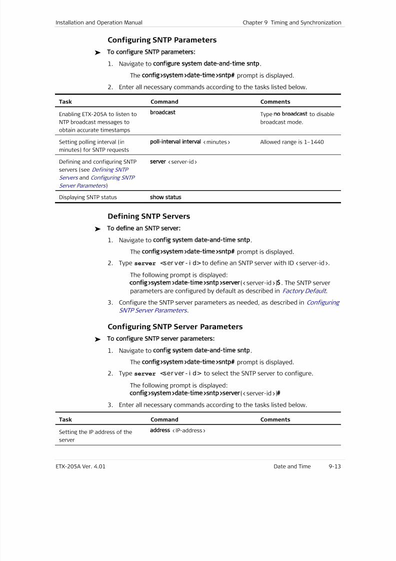
7/25/2019 Manual ETX-205A
http://slidepdf.com/reader/full/manual-etx-205a 277/409
Installation and Operation Manual Chapter 9 Timing and Synchronization
ETX-205A Ver. 4.01 Date and Time 9-13
Configuring SNTP Parameters
To configure SNTP parameters:
1. Navigate to configure system date-and-time sntp.
The config>system>date-time>sntp# prompt is displayed.
2. Enter all necessary commands according to the tasks listed below.
Task Command Comments
Enabling ETX-205A to listen to
NTP broadcast messages to
obtain accurate timestamps
broadcast Type no broadcast to disable
broadcast mode.
Setting polling interval (in
minutes) for SNTP requests
poll-interval interval <minutes> Allowed range is 1–1440
Defining and configuring SNTP
servers (see Defining SNTP
Servers and Configuring SNTP
Server Parameters )
server <server-id>
Displaying SNTP statusshow status
Defining SNTP Servers
To define an SNTP server:
1. Navigate to config system date-and-time sntp.
The config>system>date-time>sntp# prompt is displayed.
2. Type server <ser ver - i d> to define an SNTP server with ID <server-id>.
The following prompt is displayed:
config>system>date-time>sntp>server(<server-id>)$. The SNTP server
parameters are configured by default as described in Factory Default .
3. Configure the SNTP server parameters as needed, as described in Configuring
SNTP Server Parameters .
Configuring SNTP Server Parameters
To configure SNTP server parameters:
1. Navigate to config system date-and-time sntp.
The config>system>date-time>sntp# prompt is displayed.
2. Type server <server - i d> to select the SNTP server to configure.
The following prompt is displayed:
config>system>date-time>sntp>server(<server-id>)#
3. Enter all necessary commands according to the tasks listed below.
Task Command Comments
Setting the IP address of the
server
address <IP-address>
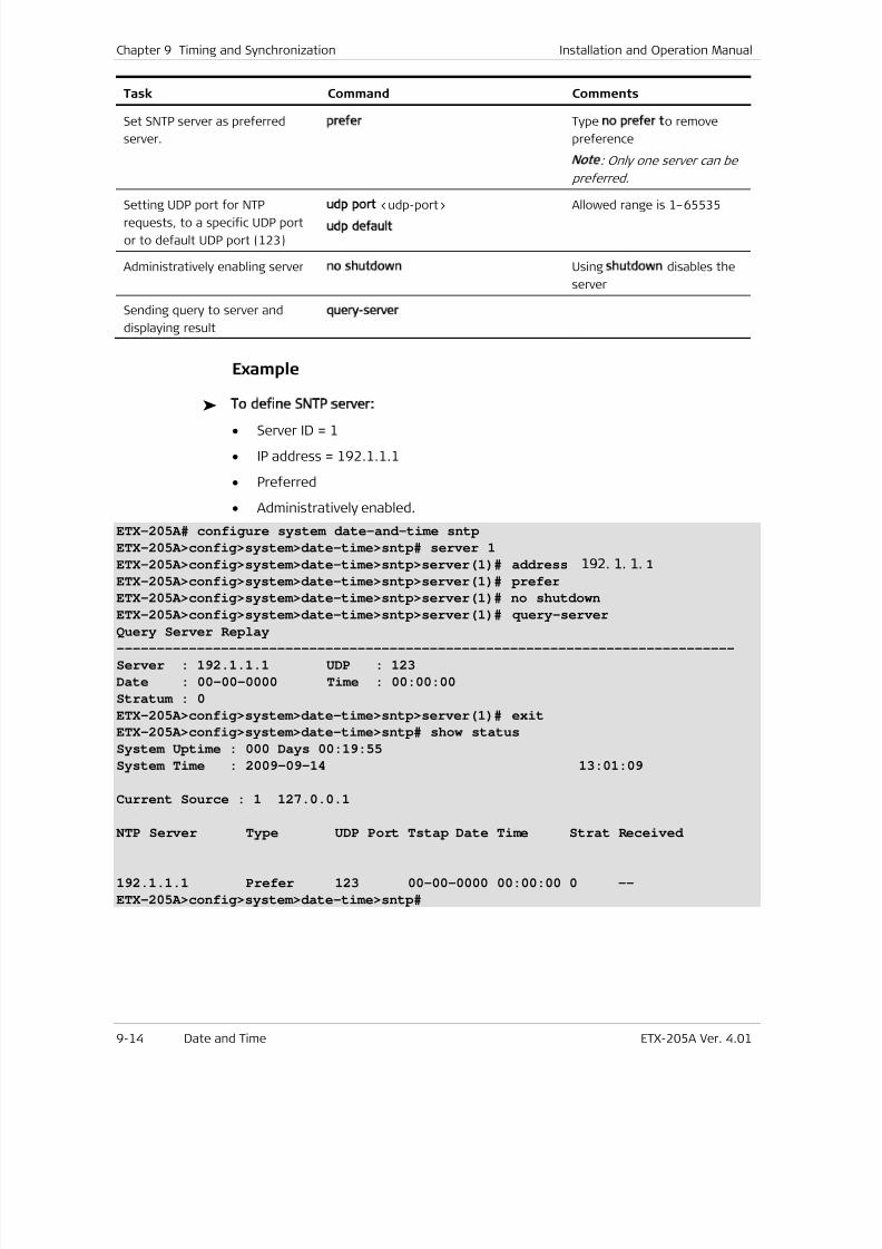
7/25/2019 Manual ETX-205A
http://slidepdf.com/reader/full/manual-etx-205a 278/409
Chapter 9 Timing and Synchronization Installation and Operation Manual
9-14 Date and Time ETX-205A Ver. 4.01
Task Command Comments
Set SNTP server as preferred
server.
prefer Type no prefer to remove
preference
Note
: Only one server can be
preferred.
Setting UDP port for NTPrequests, to a specific UDP port
or to default UDP port (123)
udp port <udp-port>
udp default
Allowed range is 1–65535
Administratively enabling server no shutdown Using shutdown disables the
server
Sending query to server and
displaying result
query-server
Example
To define SNTP server:
• Server ID = 1
• IP address = 192.1.1.1
• Preferred
• Administratively enabled.
ETX-205A# configure system date-and-time sntp
ETX-205A>config>system>date-time>sntp# server 1
ETX-205A>config>system>date-time>sntp>server(1)# address 192. 1. 1. 1ETX-205A>config>system>date-time>sntp>server(1)# prefer
ETX-205A>config>system>date-time>sntp>server(1)# no shutdown
ETX-205A>config>system>date-time>sntp>server(1)# query-server
Query Server Replay
-----------------------------------------------------------------------------
Server : 192.1.1.1 UDP : 123
Date : 00-00-0000 Time : 00:00:00
Stratum : 0
ETX-205A>config>system>date-time>sntp>server(1)# exit
ETX-205A>config>system>date-time>sntp# show status
System Uptime : 000 Days 00:19:55
System Time : 2009-09-14 13:01:09
Current Source : 1 127.0.0.1
NTP Server Type UDP Port Tstap Date Time Strat Received
192.1.1.1 Prefer 123 00-00-0000 00:00:00 0 --
ETX-205A>config>system>date-time>sntp#
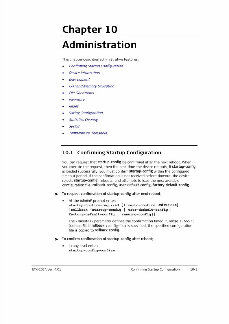
7/25/2019 Manual ETX-205A
http://slidepdf.com/reader/full/manual-etx-205a 279/409
ETX-205A Ver. 4.01 Confirming Startup Configuration 10-1
Chapter 10
Administration
This chapter describes administrative features:
• Confirming Startup Configuration
• Device Information
• Environment
• CPU and Memory Utilization
• File Operations
• Inventory
•
Reset• Saving Configuration
• Statistics Clearing
• Syslog
• Temperature Threshold .
10.1 Confirming Startup Configuration
You can request that startup-config be confirmed after the next reboot. Whenyou execute the request, then the next time the device reboots, if startup-config
is loaded successfully, you must confirm startup-config within the configured
timeout period. If the confirmation is not received before timeout, the device
rejects startup-config, reboots, and attempts to load the next available
configuration file (rollback-config, user-default-config, factory-default-config).
To request confirmation of startup-config after next reboot;
• At the admin# prompt enter:startup-confirm-required [ time-to-confirm <mi nut es>]
[ rollback startup-config | user-default-config |
factory-default-config | running-config] The <minutes> parameter defines the confirmation timeout, range 1–65535
(default 5). If rollback <config-file> is specified, the specified configuration
file is copied to rollback-config.
To confirm confirmation of startup-config after reboot;
• In any level enter:startup-config-confirm
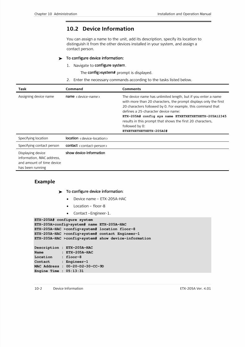
7/25/2019 Manual ETX-205A
http://slidepdf.com/reader/full/manual-etx-205a 280/409
Chapter 10 Administration Installation and Operation Manual
10-2 Device Information ETX-205A Ver. 4.01
10.2 Device Information
You can assign a name to the unit, add its description, specify its location to
distinguish it from the other devices installed in your system, and assign a
contact person.
To configure device information:
1. Navigate to configure system.
The config>system# prompt is displayed.
2. Enter the necessary commands according to the tasks listed below.
Task Command Comments
Assigning device name name <device-name> The device name has unlimited length, but if you enter a name
with more than 20 characters, the prompt displays only the first
20 characters followed by 0. For example, this command that
defines a 25-character device name:
ETX-205A# config sys name ETXETXETXETXETX-205A1234
results in this prompt that shows the first 20 characters,
followed by 0:
ETXETXETXETXETX-205A0#
Specifying locationlocation <device-location>
Specifying contact personcontact <contact-person>
Displaying device
information, MAC address,
and amount of time device
has been running
show device-information
Example
To configure device information:
• Device name – ETX-205A-HAC
• Location – floor-8
• Contact –Engineer-1.
ETX-205A# configure system
ETX-205A>config>system# name ETX-205A-HAC
ETX-205A-HAC >config>system# location floor-8ETX-205A-HAC >config>system# contact Engineer-1
ETX-205A-HAC >config>system# show device-information
Description : ETX-205A-HAC
Name : ETX-205A-HAC
Location : floor-8
Contact : Engineer-1
MAC Address : 00-20-D2-30-CC-9D
Engine Time : 05:13:31
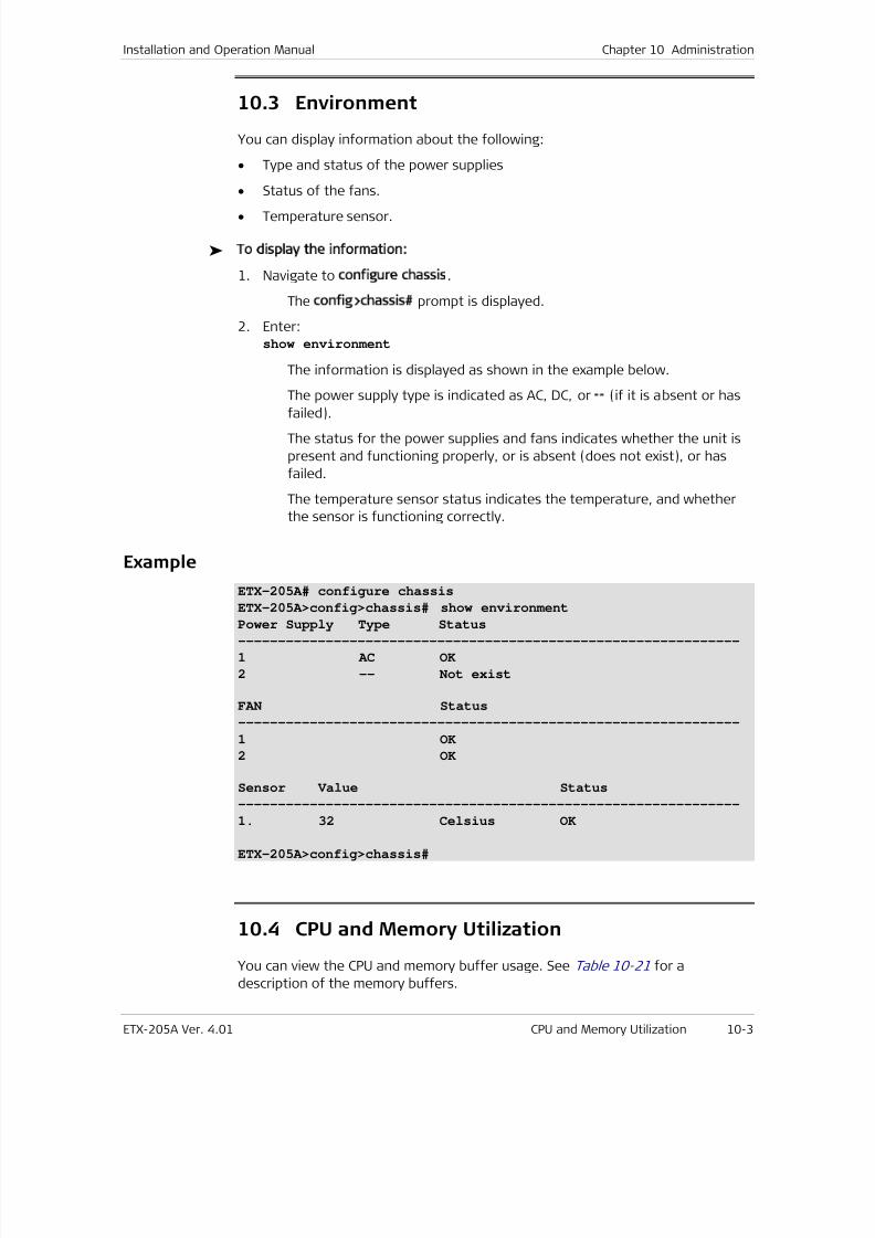
7/25/2019 Manual ETX-205A
http://slidepdf.com/reader/full/manual-etx-205a 281/409
Installation and Operation Manual Chapter 10 Administration
ETX-205A Ver. 4.01 CPU and Memory Utilization 10-3
10.3 Environment
You can display information about the following:
• Type and status of the power supplies
• Status of the fans.
• Temperature sensor.
To display the information:
1. Navigate to configure chassis.
The config>chassis# prompt is displayed.
2. Enter:show environment
The information is displayed as shown in the example below.
The power supply type is indicated as AC, DC, or -- (if it is absent or has
failed).
The status for the power supplies and fans indicates whether the unit is
present and functioning properly, or is absent (does not exist), or has
failed.
The temperature sensor status indicates the temperature, and whether
the sensor is functioning correctly.
Example
ETX-205A# configure chassis
ETX-205A>config>chassis# show environment
Power Supply Type Status
---------------------------------------------------------------
1 AC OK
2 -- Not exist
FAN Status
---------------------------------------------------------------
1 OK
2 OK
Sensor Value Status
---------------------------------------------------------------
1. 32 Celsius OK
ETX-205A>config>chassis#
10.4 CPU and Memory Utilization
You can view the CPU and memory buffer usage. See Table 10-21 for a
description of the memory buffers.
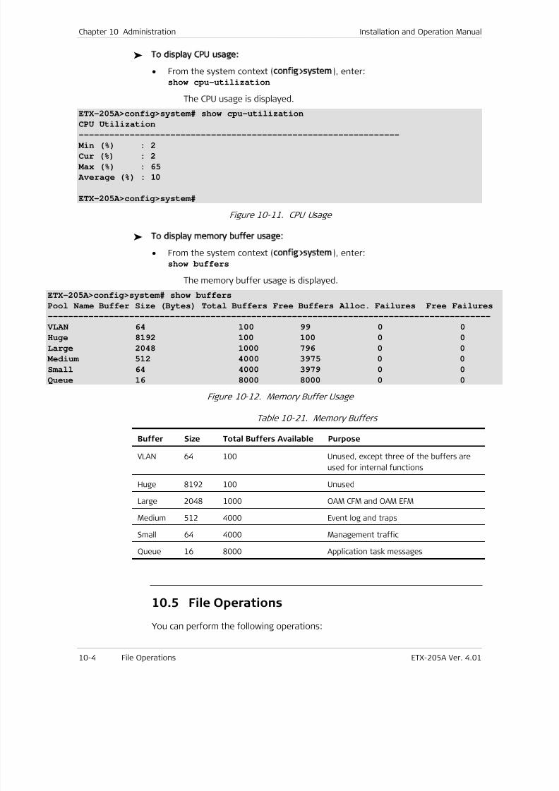
7/25/2019 Manual ETX-205A
http://slidepdf.com/reader/full/manual-etx-205a 282/409
Chapter 10 Administration Installation and Operation Manual
10-4 File Operations ETX-205A Ver. 4.01
To display CPU usage:
• From the system context (config>system), enter:show cpu-utilization
The CPU usage is displayed.
ETX-205A>config>system# show cpu-utilization
CPU Utilization
---------------------------------------------------------------
Min (%) : 2
Cur (%) : 2
Max (%) : 65
Average (%) : 10
ETX-205A>config>system#
Figure 10-11. CPU Usage
To display memory buffer usage:
• From the system context (config>system), enter:
show buffers
The memory buffer usage is displayed.
ETX-205A>config>system# show buffers
Pool Name Buffer Size (Bytes) Total Buffers Free Buffers Alloc. Failures Free Failures
---------------------------------------------------------------------------------------
VLAN 64 100 99 0 0
Huge 8192 100 100 0 0
Large 2048 1000 796 0 0
Medium 512 4000 3975 0 0
Small 64 4000 3979 0 0
Queue 16 8000 8000 0 0
Figure 10-12. Memory Buffer Usage
Table 10-21. Memory Buffers
Buffer Size Total Buffers Available Purpose
VLAN 64 100 Unused, except three of the buffers are
used for internal functions
Huge 8192 100 Unused
Large 2048 1000 OAM CFM and OAM EFM
Medium 512 4000 Event log and traps
Small 64 4000 Management traffic
Queue 16 8000 Application task messages
10.5 File Operations
You can perform the following operations:
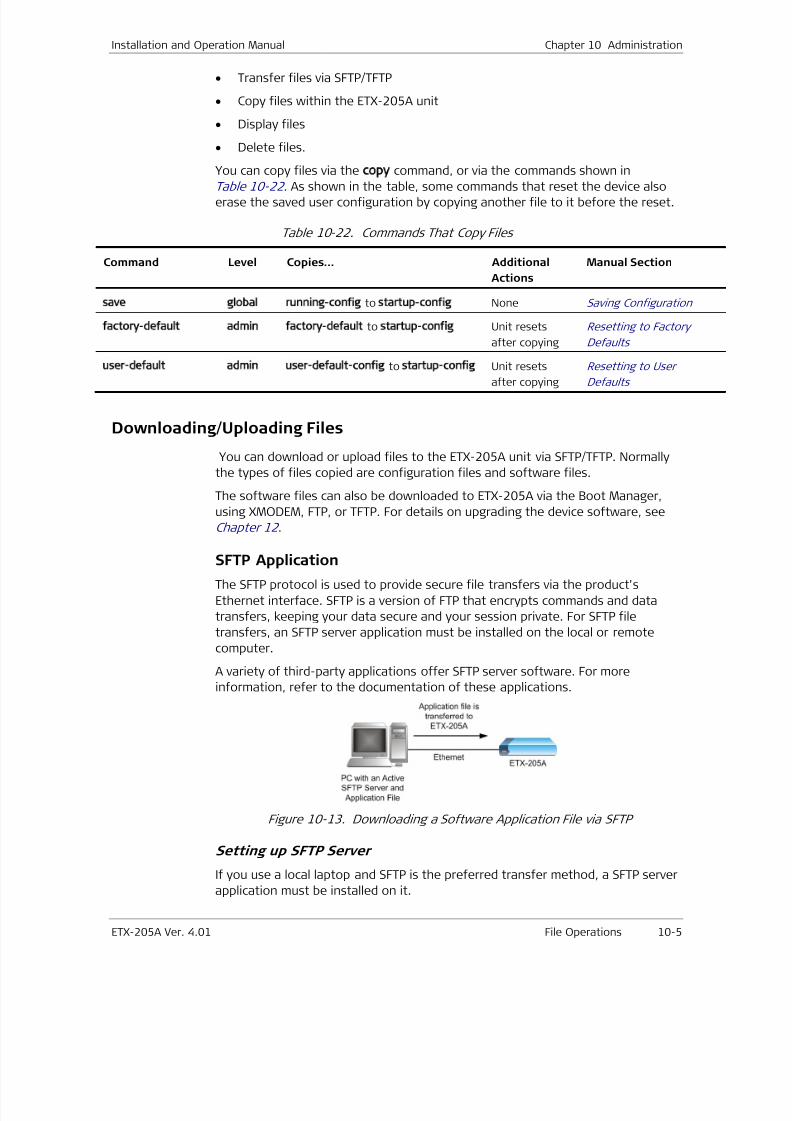
7/25/2019 Manual ETX-205A
http://slidepdf.com/reader/full/manual-etx-205a 283/409
Installation and Operation Manual Chapter 10 Administration
ETX-205A Ver. 4.01 File Operations 10-5
• Transfer files via SFTP/TFTP
• Copy files within the ETX-205A unit
• Display files
• Delete files.
You can copy files via the copy command, or via the commands shown in
Table 10-22 . As shown in the table, some commands that reset the device alsoerase the saved user configuration by copying another file to it before the reset.
Table 10-22. Commands That Copy Files
Command Level Copies… Additional
Actions
Manual Section
save global running-config to startup-config None Saving Configuration
factory-default admin factory-default to startup-config Unit resets
after copying
Resetting to Factory
Defaults
user-default admin user-default-config to startup-config Unit resets
after copying
Resetting to User
Defaults
Downloading/Uploading Files
You can download or upload files to the ETX-205A unit via SFTP/TFTP. Normally
the types of files copied are configuration files and software files.
The software files can also be downloaded to ETX-205A via the Boot Manager,
using XMODEM, FTP, or TFTP. For details on upgrading the device software, see
Chapter 12 .
SFTP ApplicationThe SFTP protocol is used to provide secure file transfers via the product's
Ethernet interface. SFTP is a version of FTP that encrypts commands and data
transfers, keeping your data secure and your session private. For SFTP file
transfers, an SFTP server application must be installed on the local or remote
computer.
A variety of third-party applications offer SFTP server software. For more
information, refer to the documentation of these applications.
Figure 10-13. Downloading a Software Application File via SFTP
Setting up SFTP Server
If you use a local laptop and SFTP is the preferred transfer method, a SFTP server
application must be installed on it.
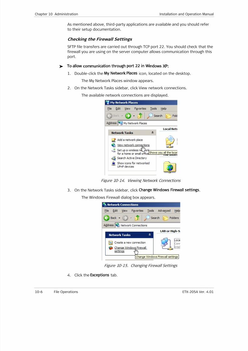
7/25/2019 Manual ETX-205A
http://slidepdf.com/reader/full/manual-etx-205a 284/409
Chapter 10 Administration Installation and Operation Manual
10-6 File Operations ETX-205A Ver. 4.01
As mentioned above, third-party applications are available and you should refer
to their setup documentation.
Checking the Firewall Settings
SFTP file transfers are carried out through TCP port 22. You should check that the
firewall you are using on the server computer allows communication through this
port.
To allow communication through port 22 in Windows XP:
1. Double-click the My Network Places icon, located on the desktop.
The My Network Places window appears.
2. On the Network Tasks sidebar, click View network connections.
The available network connections are displayed.
Figure 10-14. Viewing Network Connections
3. On the Network Tasks sidebar, click Change Windows Firewall settings.
The Windows Firewall dialog box appears.
Figure 10-15. Changing Firewall Settings
4. Click the Exceptions tab.
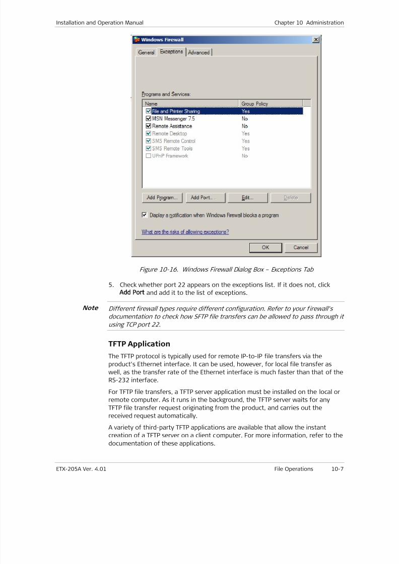
7/25/2019 Manual ETX-205A
http://slidepdf.com/reader/full/manual-etx-205a 285/409
Installation and Operation Manual Chapter 10 Administration
ETX-205A Ver. 4.01 File Operations 10-7
Figure 10-16. Windows Firewall Dialog Box – Exceptions Tab
5. Check whether port 22 appears on the exceptions list. If it does not, click
Add Port and add it to the list of exceptions.
Different firewall types require different configuration. Refer to your firewall's
documentation to check how SFTP file transfers can be allowed to pass through it
using TCP port 22.
TFTP Application
The TFTP protocol is typically used for remote IP-to-IP file transfers via the
product's Ethernet interface. It can be used, however, for local file transfer as
well, as the transfer rate of the Ethernet interface is much faster than that of theRS-232 interface.
For TFTP file transfers, a TFTP server application must be installed on the local or
remote computer. As it runs in the background, the TFTP server waits for any
TFTP file transfer request originating from the product, and carries out the
received request automatically.
A variety of third-party TFTP applications are available that allow the instant
creation of a TFTP server on a client computer. For more information, refer to the
documentation of these applications.
Note
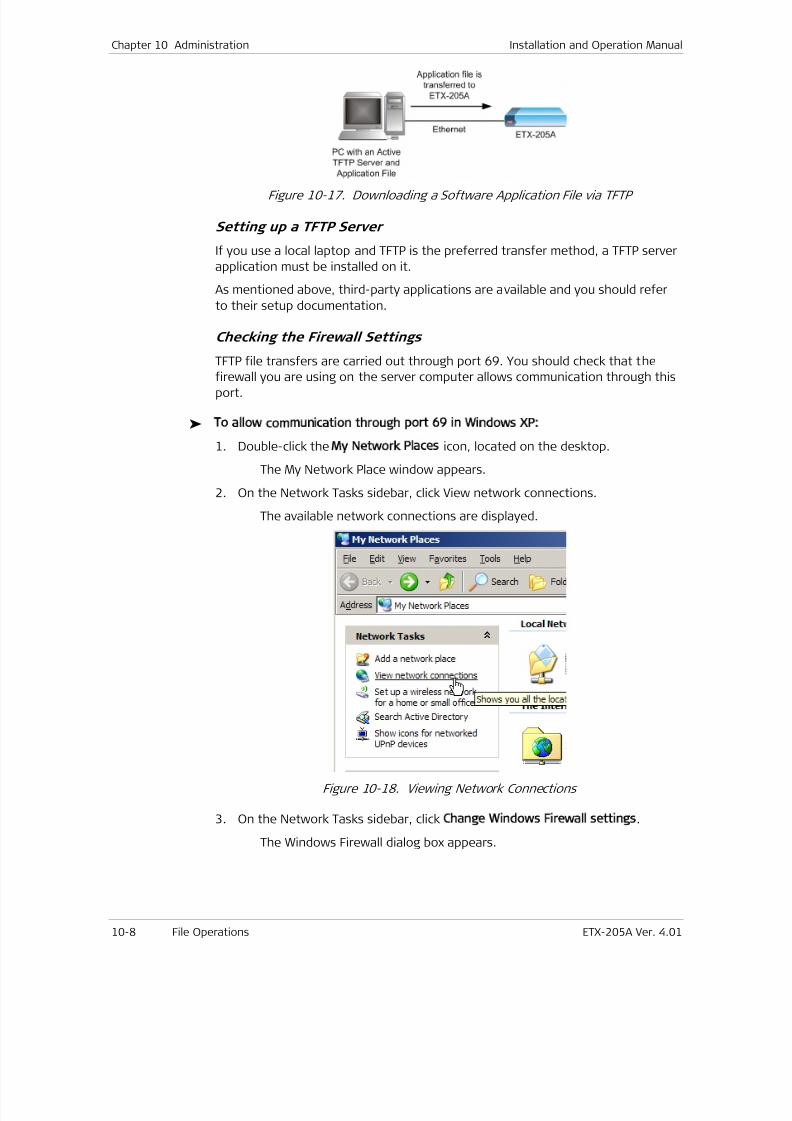
7/25/2019 Manual ETX-205A
http://slidepdf.com/reader/full/manual-etx-205a 286/409
Chapter 10 Administration Installation and Operation Manual
10-8 File Operations ETX-205A Ver. 4.01
Figure 10-17. Downloading a Software Application File via TFTP
Setting up a TFTP Server
If you use a local laptop and TFTP is the preferred transfer method, a TFTP server
application must be installed on it.
As mentioned above, third-party applications are available and you should refer
to their setup documentation.
Checking the Firewall Settings
TFTP file transfers are carried out through port 69. You should check that the
firewall you are using on the server computer allows communication through thisport.
To allow communication through port 69 in Windows XP:
1. Double-click the My Network Places icon, located on the desktop.
The My Network Place window appears.
2. On the Network Tasks sidebar, click View network connections.
The available network connections are displayed.
Figure 10-18. Viewing Network Connections
3. On the Network Tasks sidebar, click Change Windows Firewall settings.
The Windows Firewall dialog box appears.
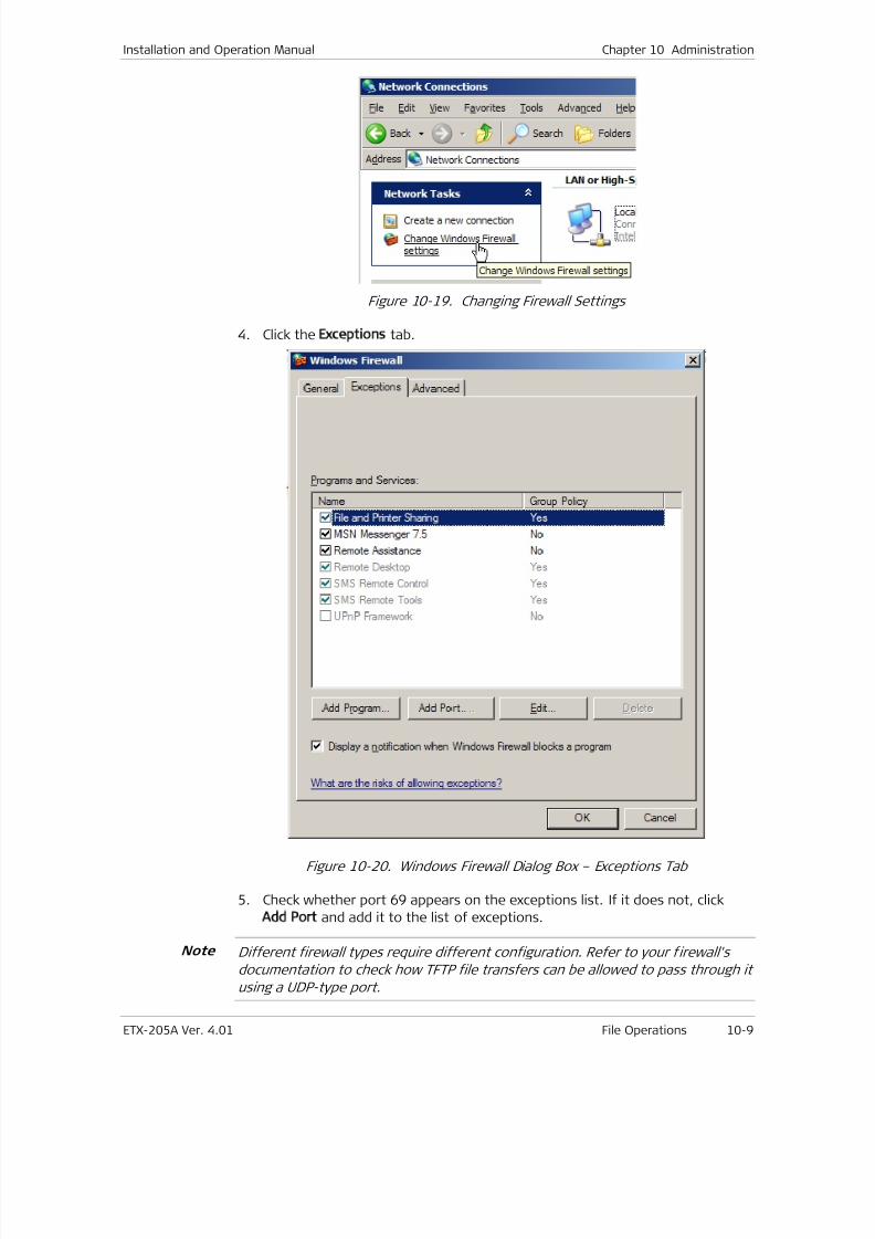
7/25/2019 Manual ETX-205A
http://slidepdf.com/reader/full/manual-etx-205a 287/409
Installation and Operation Manual Chapter 10 Administration
ETX-205A Ver. 4.01 File Operations 10-9
Figure 10-19. Changing Firewall Settings
4. Click the Exceptions tab.
Figure 10-20. Windows Firewall Dialog Box – Exceptions Tab
5. Check whether port 69 appears on the exceptions list. If it does not, click
Add Port and add it to the list of exceptions.
Different firewall types require different configuration. Refer to your firewall's
documentation to check how TFTP file transfers can be allowed to pass through it
using a UDP-type port.
Note
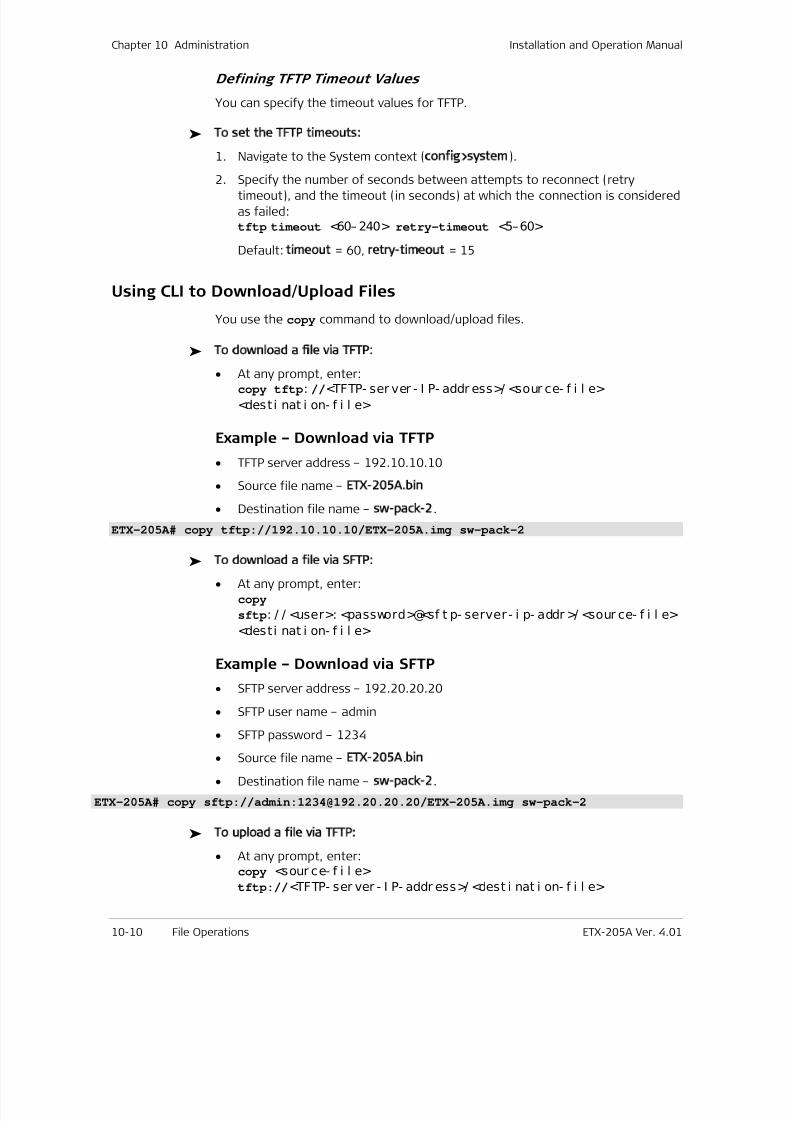
7/25/2019 Manual ETX-205A
http://slidepdf.com/reader/full/manual-etx-205a 288/409
Chapter 10 Administration Installation and Operation Manual
10-10 File Operations ETX-205A Ver. 4.01
Defining TFTP Timeout Values
You can specify the timeout values for TFTP.
To set the TFTP timeouts:
1. Navigate to the System context (config>system).
2. Specify the number of seconds between attempts to reconnect (retrytimeout), and the timeout (in seconds) at which the connection is considered
as failed:tftp timeout <60– 240> retry-timeout <5–60>
Default: timeout = 60, retry-timeout = 15
Using CLI to Download/Upload Files
You use the copy command to download/upload files.
To download a file via TFTP:
• At any prompt, enter:copy tftp: //<TFTP- ser ver - I P- addr ess>/ <sour ce- f i l e>
<desti nat i on- f i l e>
Example – Download via TFTP
• TFTP server address – 192.10.10.10
• Source file name – ETX-205A.bin
• Destination file name – sw-pack-2.
ETX-205A# copy tftp://192.10.10.10/ETX-205A.img sw-pack-2
To download a file via SFTP:
• At any prompt, enter:copy
sftp: / / <user>: <password>@<sf t p- server - i p- addr >/ <sour ce- f i l e>
<desti nat i on- f i l e>
Example – Download via SFTP
• SFTP server address – 192.20.20.20
• SFTP user name – admin
• SFTP password – 1234
• Source file name – ETX-205A.bin
• Destination file name – sw-pack-2.
ETX-205A# copy sftp://admin:[email protected]/ETX-205A.img sw-pack-2
To upload a file via TFTP:
• At any prompt, enter:copy <sour ce- f i l e>
tftp://<TFTP- ser ver - I P- addr ess>/ <dest i nat i on- f i l e>
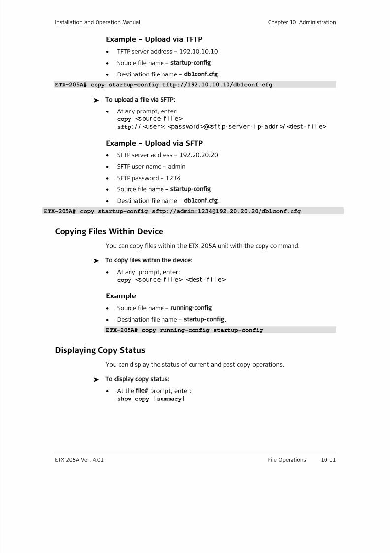
7/25/2019 Manual ETX-205A
http://slidepdf.com/reader/full/manual-etx-205a 289/409
Installation and Operation Manual Chapter 10 Administration
ETX-205A Ver. 4.01 File Operations 10-11
Example – Upload via TFTP
• TFTP server address – 192.10.10.10
• Source file name – startup-config
• Destination file name – db1conf.cfg.
ETX-205A# copy startup-config tftp://192.10.10.10/db1conf.cfg
To upload a file via SFTP:
• At any prompt, enter:copy <sour ce- f i l e>
sftp: / / <user>: <password>@<sf t p- server - i p- addr >/ <dest - f i l e>
Example – Upload via SFTP
• SFTP server address – 192.20.20.20
• SFTP user name – admin
• SFTP password – 1234
• Source file name – startup-config
• Destination file name – db1conf.cfg.
ETX-205A# copy startup-config sftp://admin:[email protected]/db1conf.cfg
Copying Files Within Device
You can copy files within the ETX-205A unit with the copy command.
To copy files within the device:
• At any prompt, enter:copy <sour ce- f i l e> <dest - f i l e>
Example
• Source file name – running-config
• Destination file name – startup-config.
ETX-205A# copy running-config startup-config
Displaying Copy Status
You can display the status of current and past copy operations.
To display copy status:
• At the file# prompt, enter:show copy [ summary]
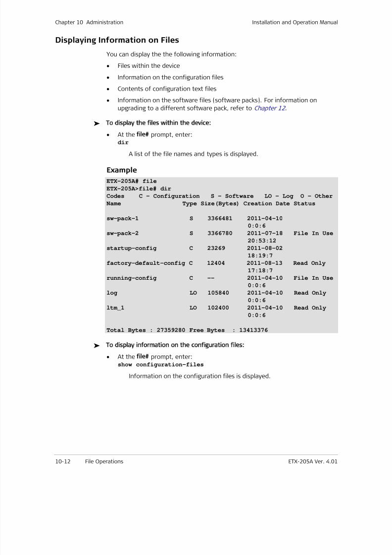
7/25/2019 Manual ETX-205A
http://slidepdf.com/reader/full/manual-etx-205a 290/409
Chapter 10 Administration Installation and Operation Manual
10-12 File Operations ETX-205A Ver. 4.01
Displaying Information on Files
You can display the the following information:
• Files within the device
• Information on the configuration files
• Contents of configuration text files
• Information on the software files (software packs). For information on
upgrading to a different software pack, refer to Chapter 12 .
To display the files within the device:
• At the file# prompt, enter:dir
A list of the file names and types is displayed.
Example
ETX-205A# file
ETX-205A>file# dir
Codes C – Configuration S - Software LO - Log O - Other
Name Type Size(Bytes) Creation Date Status
sw-pack-1 S 3366481 2011-04-10
0:0:6
sw-pack-2 S 3366780 2011-07-18 File In Use
20:53:12
startup-config C 23269 2011-08-02
18:19:7
factory-default-config C 12404 2011-08-13 Read Only
17:18:7
running-config C -- 2011-04-10 File In Use0:0:6
log LO 105840 2011-04-10 Read Only
0:0:6
ltm_1 LO 102400 2011-04-10 Read Only
0:0:6
Total Bytes : 27359280 Free Bytes : 13413376
To display information on the configuration files:
• At the file# prompt, enter:show configuration-files
Information on the configuration files is displayed.
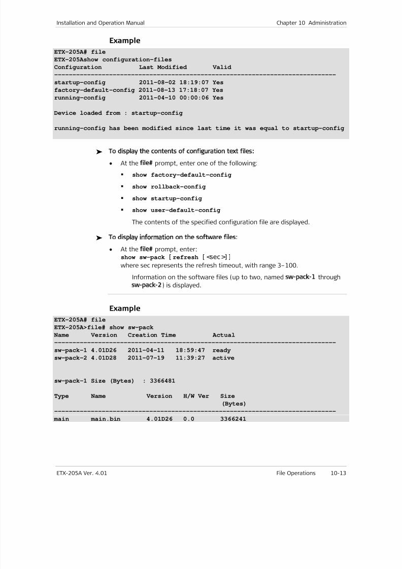
7/25/2019 Manual ETX-205A
http://slidepdf.com/reader/full/manual-etx-205a 291/409
Installation and Operation Manual Chapter 10 Administration
ETX-205A Ver. 4.01 File Operations 10-13
Example
ETX-205A# file
ETX-205Ashow configuration-files
Configuration Last Modified Valid
-----------------------------------------------------------------------------
startup-config 2011-08-02 18:19:07 Yes
factory-default-config 2011-08-13 17:18:07 Yes
running-config 2011-04-10 00:00:06 Yes
Device loaded from : startup-config
running-config has been modified since last time it was equal to startup-config
To display the contents of configuration text files:
• At the file# prompt, enter one of the following:
show factory-default-config
show rollback-config show startup-config
show user-default-config
The contents of the specified configuration file are displayed.
To display information on the software files:
• At the file# prompt, enter:show sw-pack [ refresh [ <sec>] ]
where sec represents the refresh timeout, with range 3–100.
Information on the software files (up to two, named sw-pack-1 through
sw-pack-2) is displayed.
Example
ETX-205A# file
ETX-205A>file# show sw-pack
Name Version Creation Time Actual
-----------------------------------------------------------------------------
sw-pack-1 4.01D26 2011-04-11 18:59:47 ready
sw-pack-2 4.01D28 2011-07-19 11:39:27 active
sw-pack-1 Size (Bytes) : 3366481
Type Name Version H/W Ver Size
(Bytes)
-----------------------------------------------------------------------------
main main.bin 4.01D26 0.0 3366241
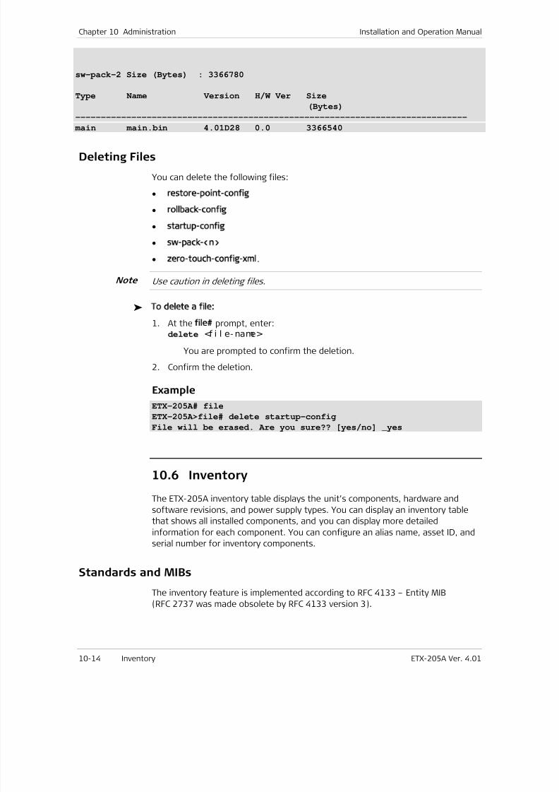
7/25/2019 Manual ETX-205A
http://slidepdf.com/reader/full/manual-etx-205a 292/409
Chapter 10 Administration Installation and Operation Manual
10-14 Inventory ETX-205A Ver. 4.01
sw-pack-2 Size (Bytes) : 3366780
Type Name Version H/W Ver Size
(Bytes)
-----------------------------------------------------------------------------
main main.bin 4.01D28 0.0 3366540
Deleting Files
You can delete the following files:
• restore-point-config
• rollback-config
• startup-config
• sw-pack-<n>
•
zero-touch-config-xml.
Use caution in deleting files.
To delete a file:
1. At the file# prompt, enter:delete <f i l e- name>
You are prompted to confirm the deletion.
2. Confirm the deletion.
ExampleETX-205A# file
ETX-205A>file# delete startup-config
File will be erased. Are you sure?? [yes/no] _yes
10.6 Inventory
The ETX-205A inventory table displays the unit’s components, hardware and
software revisions, and power supply types. You can display an inventory table
that shows all installed components, and you can display more detailed
information for each component. You can configure an alias name, asset ID, and
serial number for inventory components.
Standards and MIBs
The inventory feature is implemented according to RFC 4133 – Entity MIB
(RFC 2737 was made obsolete by RFC 4133 version 3).
Note
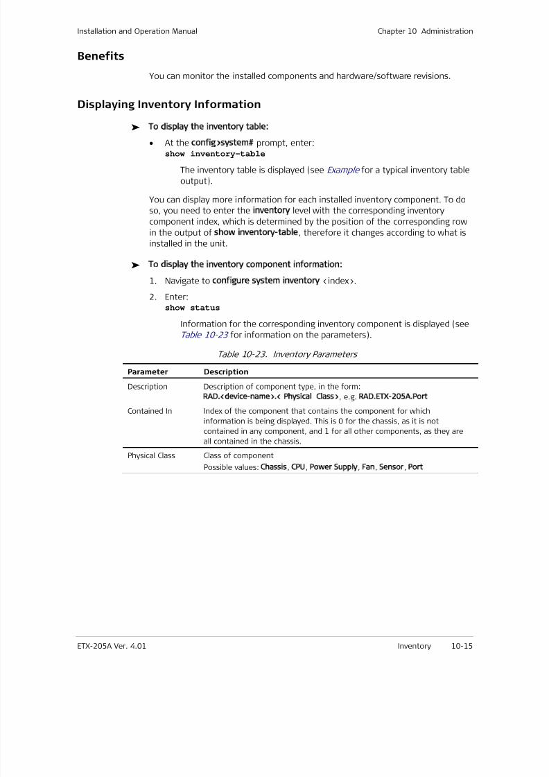
7/25/2019 Manual ETX-205A
http://slidepdf.com/reader/full/manual-etx-205a 293/409
Installation and Operation Manual Chapter 10 Administration
ETX-205A Ver. 4.01 Inventory 10-15
Benefits
You can monitor the installed components and hardware/software revisions.
Displaying Inventory Information
To display the inventory table:
• At the config>system# prompt, enter:show inventory-table
The inventory table is displayed (see Example for a typical inventory table
output).
You can display more information for each installed inventory component. To do
so, you need to enter the inventory level with the corresponding inventory
component index, which is determined by the position of the corresponding row
in the output of show inventory-table, therefore it changes according to what is
installed in the unit.
To display the inventory component information:
1. Navigate to configure system inventory <index>.
2. Enter:show status
Information for the corresponding inventory component is displayed (see
Table 10-23 for information on the parameters).
Table 10-23. Inventory Parameters
Parameter Description
Description Description of component type, in the form:RAD.<device-name>.< Physical Class>, e.g. RAD.ETX-205A.Port
Contained In Index of the component that contains the component for which
information is being displayed. This is 0 for the chassis, as it is not
contained in any component, and 1 for all other components, as they are
all contained in the chassis.
Physical Class Class of component
Possible values: Chassis, CPU, Power Supply, Fan, Sensor, Port
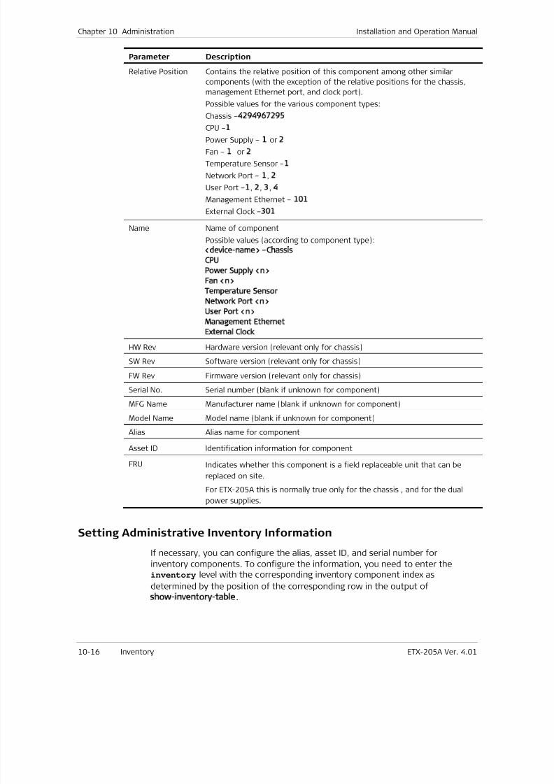
7/25/2019 Manual ETX-205A
http://slidepdf.com/reader/full/manual-etx-205a 294/409
Chapter 10 Administration Installation and Operation Manual
10-16 Inventory ETX-205A Ver. 4.01
Parameter Description
Relative Position Contains the relative position of this component among other similar
components (with the exception of the relative positions for the chassis,
management Ethernet port, and clock port).
Possible values for the various component types:
Chassis –4294967295
CPU –1 Power Supply – 1 or 2
Fan – 1 or 2
Temperature Sensor –1
Network Port – 1, 2
User Port –1, 2, 3, 4
Management Ethernet – 101
External Clock –301
Name Name of component
Possible values (according to component type):
<device-name> –Chassis
CPU Power Supply <n>
Fan <n>
Temperature Sensor
Network Port <n>
User Port <n>
Management Ethernet
External Clock
HW Rev Hardware version (relevant only for chassis)
SW Rev Software version (relevant only for chassis)
FW Rev Firmware version (relevant only for chassis)
Serial No. Serial number (blank if unknown for component)MFG Name Manufacturer name (blank if unknown for component)
Model Name Model name (blank if unknown for component)
Alias Alias name for component
Asset ID Identification information for component
FRU Indicates whether this component is a field replaceable unit that can be
replaced on site.
For ETX-205A this is normally true only for the chassis , and for the dual
power supplies.
Setting Administrative Inventory Information
If necessary, you can configure the alias, asset ID, and serial number for
inventory components. To configure the information, you need to enter theinventory level with the corresponding inventory component index as
determined by the position of the corresponding row in the output of
show-inventory-table.
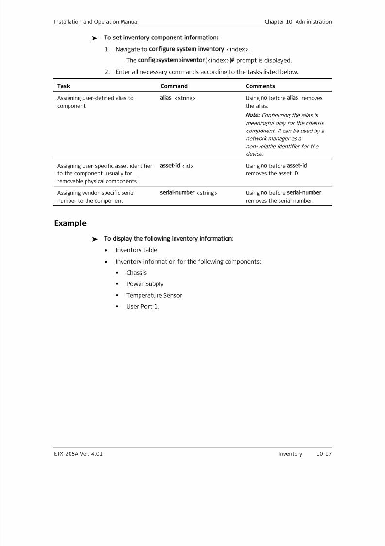
7/25/2019 Manual ETX-205A
http://slidepdf.com/reader/full/manual-etx-205a 295/409
Installation and Operation Manual Chapter 10 Administration
ETX-205A Ver. 4.01 Inventory 10-17
To set inventory component information:
1. Navigate to configure system inventory <index>.
The config>system>inventor(<index>)# prompt is displayed.
2. Enter all necessary commands according to the tasks listed below.
Task Command Comments
Assigning user-defined alias to
component
alias <string> Using no before alias removes
the alias.
Note: Configuring the alias is
meaningful only for the chassis
component. It can be used by a
network manager as a
non-volatile identifier for the
device.
Assigning user-specific asset identifier
to the component (usually for
removable physical components)
asset-id <id> Using no before asset-id
removes the asset ID.
Assigning vendor-specific serial
number to the component
serial-number <string> Using no before serial-number
removes the serial number.
Example
To display the following inventory information:
• Inventory table
• Inventory information for the following components:
Chassis
Power Supply
Temperature Sensor
User Port 1.
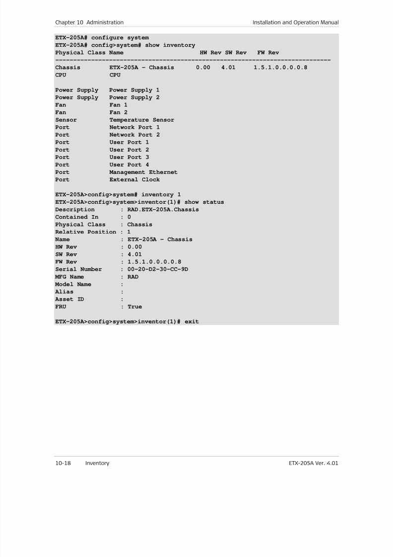
7/25/2019 Manual ETX-205A
http://slidepdf.com/reader/full/manual-etx-205a 296/409
Chapter 10 Administration Installation and Operation Manual
10-18 Inventory ETX-205A Ver. 4.01
ETX-205A# configure system
ETX-205A# config>system# show inventory
Physical Class Name HW Rev SW Rev FW Rev
-----------------------------------------------------------------------------
Chassis ETX-205A – Chassis 0.00 4.01 1.5.1.0.0.0.0.8
CPU CPU
Power Supply Power Supply 1Power Supply Power Supply 2
Fan Fan 1
Fan Fan 2
Sensor Temperature Sensor
Port Network Port 1
Port Network Port 2
Port User Port 1
Port User Port 2
Port User Port 3
Port User Port 4
Port Management Ethernet
Port External Clock
ETX-205A>config>system# inventory 1
ETX-205A>config>system>inventor(1)# show status
Description : RAD.ETX-205A.Chassis
Contained In : 0
Physical Class : Chassis
Relative Position : 1
Name : ETX-205A - Chassis
HW Rev : 0.00
SW Rev : 4.01
FW Rev : 1.5.1.0.0.0.0.8
Serial Number : 00-20-D2-30-CC-9D
MFG Name : RAD Model Name :
Alias :
Asset ID :
FRU : True
ETX-205A>config>system>inventor(1)# exit
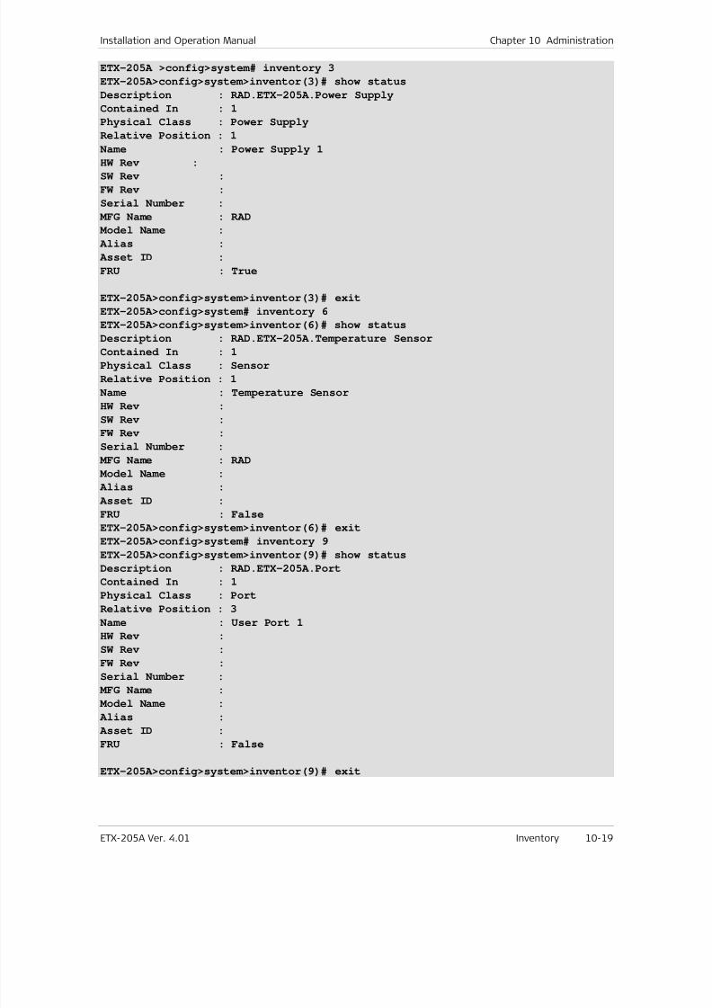
7/25/2019 Manual ETX-205A
http://slidepdf.com/reader/full/manual-etx-205a 297/409
Installation and Operation Manual Chapter 10 Administration
ETX-205A Ver. 4.01 Inventory 10-19
ETX-205A >config>system# inventory 3
ETX-205A>config>system>inventor(3)# show status
Description : RAD.ETX-205A.Power Supply
Contained In : 1
Physical Class : Power Supply
Relative Position : 1
Name : Power Supply 1
HW Rev :SW Rev :
FW Rev :
Serial Number :
MFG Name : RAD
Model Name :
Alias :
Asset ID :
FRU : True
ETX-205A>config>system>inventor(3)# exit
ETX-205A>config>system# inventory 6
ETX-205A>config>system>inventor(6)# show status
Description : RAD.ETX-205A.Temperature SensorContained In : 1
Physical Class : Sensor
Relative Position : 1
Name : Temperature Sensor
HW Rev :
SW Rev :
FW Rev :
Serial Number :
MFG Name : RAD
Model Name :
Alias :
Asset ID :FRU : False
ETX-205A>config>system>inventor(6)# exit
ETX-205A>config>system# inventory 9
ETX-205A>config>system>inventor(9)# show status
Description : RAD.ETX-205A.Port
Contained In : 1
Physical Class : Port
Relative Position : 3
Name : User Port 1
HW Rev :
SW Rev :
FW Rev :
Serial Number :
MFG Name :
Model Name :
Alias :
Asset ID :
FRU : False
ETX-205A>config>system>inventor(9)# exit
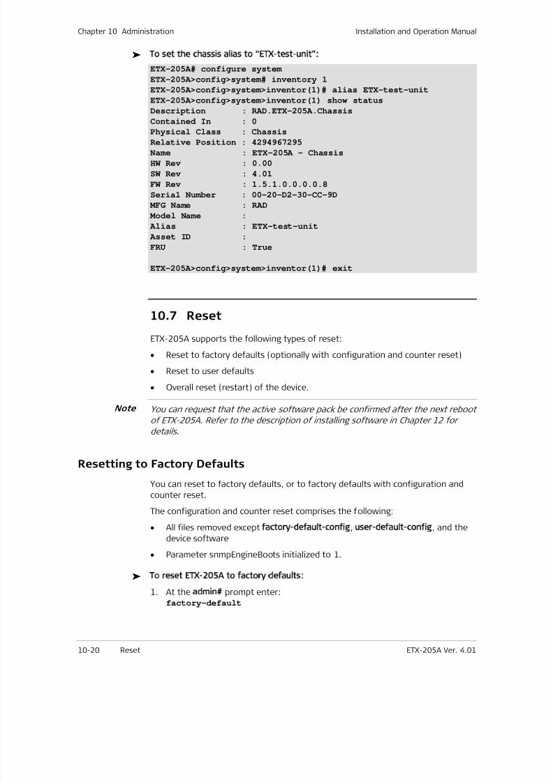
7/25/2019 Manual ETX-205A
http://slidepdf.com/reader/full/manual-etx-205a 298/409
Chapter 10 Administration Installation and Operation Manual
10-20 Reset ETX-205A Ver. 4.01
To set the chassis alias to “ETX-test-unit”:
ETX-205A# configure system
ETX-205A>config>system# inventory 1
ETX-205A>config>system>inventor(1)# alias ETX-test-unit
ETX-205A>config>system>inventor(1) show status
Description : RAD.ETX-205A.Chassis
Contained In : 0
Physical Class : ChassisRelative Position : 4294967295
Name : ETX-205A - Chassis
HW Rev : 0.00
SW Rev : 4.01
FW Rev : 1.5.1.0.0.0.0.8
Serial Number : 00-20-D2-30-CC-9D
MFG Name : RAD
Model Name :
Alias : ETX-test-unit
Asset ID :
FRU : True
ETX-205A>config>system>inventor(1)# exit
10.7 Reset
ETX-205A supports the following types of reset:
• Reset to factory defaults (optionally with configuration and counter reset)
• Reset to user defaults
•
Overall reset (restart) of the device.
You can request that the active software pack be confirmed after the next reboot
of ETX-205A. Refer to the description of installing software in Chapter 12 for
details.
Resetting to Factory Defaults
You can reset to factory defaults, or to factory defaults with configuration and
counter reset.
The configuration and counter reset comprises the following:
• All files removed except factory-default-config, user-default-config, and the
device software
• Parameter snmpEngineBoots initialized to 1.
To reset ETX-205A to factory defaults:
1. At the admin# prompt enter:factory-default
Note
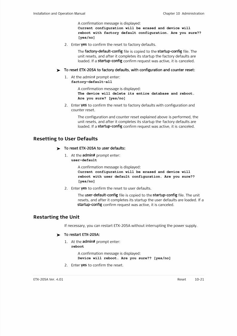
7/25/2019 Manual ETX-205A
http://slidepdf.com/reader/full/manual-etx-205a 299/409
Installation and Operation Manual Chapter 10 Administration
ETX-205A Ver. 4.01 Reset 10-21
A confirmation message is displayed:Current configuration will be erased and device will
reboot with factory default configuration. Are you sure??
[yes/no]
2. Enter yes to confirm the reset to factory defaults.
The factory-default-config file is copied to the startup-config file. The
unit resets, and after it completes its startup the factory defaults areloaded. If a startup-config confirm request was active, it is canceled.
To reset ETX-205A to factory defaults, with configuration and counter reset:
1. At the admin# prompt enter:factory-default-all
A confirmation message is displayed:The device will delete its entire database and reboot.
Are you sure? [yes/no]
2. Enter yes to confirm the reset to factory defaults with configuration and
counter reset.The configuration and counter reset explained above is performed, the
unit resets, and after it completes its startup the factory defaults are
loaded. If a startup-config confirm request was active, it is canceled.
Resetting to User Defaults
To reset ETX-205A to user defaults:
1. At the admin# prompt enter:user-default
A confirmation message is displayed:Current configuration will be erased and device will
reboot with user default configuration. Are you sure??
[yes/no]
2. Enter yes to confirm the reset to user defaults.
The user-default-config file is copied to the startup-config file. The unit
resets, and after it completes its startup the user defaults are loaded. If a
startup-config confirm request was active, it is canceled.
Restarting the Unit
If necessary, you can restart ETX-205A without interrupting the power supply.
To restart ETX-205A:
1. At the admin# prompt enter:reboot
A confirmation message is displayed:Device will reboot. Are you sure?? [yes/no]
2. Enter yes to confirm the reset.
7/25/2019 Manual ETX-205A
http://slidepdf.com/reader/full/manual-etx-205a 300/409
Chapter 10 Administration Installation and Operation Manual
10-22 Syslog ETX-205A Ver. 4.01
The unit restarts.
10.8 Saving Configuration
You must save your configuration if you wish to have it available, as it is not
saved automatically. You can save your configuration as follows:
• To save the user configuration in startup-config:
In any level enter:save
At the file# prompt enter:
copy running-config startup-config
• To save the user default configuration in user-default-config, at the file#
prompt enter:copy running-config user-default-config
10.9 Statistics Clearing
You can clear the statistics for Ethernet ports, flows, and OAM services.
To clear the statistics:
• At the device prompt, enter:clear-statistics
The statistics for Ethernet ports, flows, and OAM services are cleared.
10.10 Syslog
ETX-205A uses the Syslog protocol to generate and transport event notification
messages over IP networks to Syslog servers. The Syslog operation is compliant
with the RFC 3164 requirements.
Configuring Syslog Parameters
To configure syslog parameters:
1. Navigate to the system context (config>system).
2. Define syslog device parameters:
a. Enter:syslog device
The system switches to the syslog device context(config>system>syslog( devi ce) )
7/25/2019 Manual ETX-205A
http://slidepdf.com/reader/full/manual-etx-205a 301/409
Installation and Operation Manual Chapter 10 Administration
ETX-205A Ver. 4.01 Syslog 10-23
b. Specify the module, task, or function from which syslog messages aresent:
facility local1 | local2 | local3 | local4 | local5 |
local6 | local7
Default: local1
c. Specify the UDP port that transmits syslog messages (allowed only if
syslog message transmitting is administratively disabled):
port <udp- por t - number >
Allowed values: 1–65535
Default: 514
d. Specify the severity level. The log messages that contain severity level upto the specified level are transmitted:
severity-level critical | major | minor | warning |
event | info | debug
e. Administratively enable the transmitting of syslog messages:
no shutdown
3. Define syslog server parameters:
a. Specify the syslog server to receive syslog messages, from 1 to 5:syslog server <ser ver - i d>
The system switches to the context of the specified syslog server(config>system>syslog(server <server-ID>)).
b. Specify the IP address of the server (allowed only if the server isadministratively disabled):
address <0. 0. 0. 0–255. 255. 255. 255>
c. Specify the UDP port on the server that receives syslog messages
(allowed only if the server is administratively disabled):
port <udp- port - number>
Allowed values: 1–65535
d. Administratively enable the server (allowed only if IP address is not0.0.0.0):
no shutdown
e. Enter exit to exit the server context.
The system switches to the system context (config>system ).
Displaying Syslog Statistics
To display syslog statistics:
1. At the system context (config>system), enter:syslog device
The system switches to the syslog device context
(config>system>syslog(device))
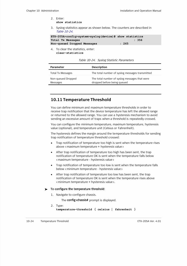
7/25/2019 Manual ETX-205A
http://slidepdf.com/reader/full/manual-etx-205a 302/409
Chapter 10 Administration Installation and Operation Manual
10-24 Temperature Threshold ETX-205A Ver. 4.01
2. Enter:show statistics
3. Syslog statistics appear as shown below. The counters are described in
Table 10-24 .
ETX-205A>config>system>syslog(device)# show statistics
Total Tx Messages : 356
Non-queued Dropped Messages : 265
4. To clear the statistics, enter:clear-statistics
Table 10-24. Syslog Statistic Parameters
Parameter Description
Total Tx Messages The total number of syslog messages transmitted
Non-queued Dropped
Messages
The total number of syslog messages that were
dropped before being queued
10.11 Temperature Threshold
You can define minimum and maximum temperature thresholds in order to
receive trap notification that the device temperature has left the allowed range
or returned to the allowed range. You can use a hysteresis mechanism to avoid
sending an excessive amount of traps when a threshold is repeatedly crossed.
You can configure the minimum temperature, maximum temperature, hysteresis
value (optional), and temperature unit (Celsius or Fahrenheit).
The hysteresis defines the margin around the temperature thresholds for sendingtrap notification of temperature threshold crossed:
• Trap notification of temperature too high is sent when the temperature rises
above <maximum temperature + hysteresis value>
• After trap notification of temperature too high has been sent, the trap
notification of temperature OK is sent when the temperature falls below
<maximum temperature - hysteresis value>
• Trap notification of temperature too low is sent when the temperature falls
below <minimum temperature - hysteresis value>
• After trap notification of temperature too low has been sent, the trap
notification of temperature OK is sent when the temperature rises above
<minimum temperature + hysteresis value>.
To configure the temperature threshold:
1. Navigate to configure chassis.
The config>chassis# prompt is displayed.
2. Type:temperature-threshold celsius | fahrenheit

7/25/2019 Manual ETX-205A
http://slidepdf.com/reader/full/manual-etx-205a 303/409
Installation and Operation Manual Chapter 10 Administration
ETX-205A Ver. 4.01 Temperature Threshold 10-25
min <mi n- val ue> max <max- val ue>
[ hysteresis <hyster esi s- val ue> ]
The temperature thresholds are set as specified.
Example
To define temperature thresholds:
• Minimum temperature = -20 degrees Celsius
• Maximum temperature = 50 degrees Celsius
• Hysteresis = 4.
ETX-205A# configure chassis
ETX-205A#config>chassis# temperature-threshold celsius min -20 max 50 hysteresis 4
ETX-205A# config>chassis#

7/25/2019 Manual ETX-205A
http://slidepdf.com/reader/full/manual-etx-205a 304/409
Chapter 10 Administration Installation and Operation Manual
10-26 Temperature Threshold ETX-205A Ver. 4.01
7/25/2019 Manual ETX-205A
http://slidepdf.com/reader/full/manual-etx-205a 305/409
ETX-205A Ver. 4.01 Detecting Problems 11-1
Chapter 11
Monitoring and
Diagnostics
The following are described in this chapter:
• Detecting problems
• Alarms and traps
• Performing diagnostic tests.
11.1 Detecting Problems
The LED indicators indicate errors on the hardware level.
LEDs
If an LED is red, that usually indicates there is a problem. Check the port that is
associated with the LED to further investigate the problem. Refer to Chapter 3
for a description of the unit LEDs.
Alarms and Traps
Alarms serve as notification of a fault in the device, and are indicated by an entry
in the alarm and event history log, and/or an SNMP trap to a management
station. Refer to Handling Alarms and Events for further details on alarms,
events, and traps.
Statistic Counters
Statistic counters provide information on possible abnormal behavior and failures.
You can collect statistics on the following:
• Ethernet ports
• Flows
• RADIUS server
• OAM CFM.
For further information, refer to the relevant sections in Chapter 6 –10 and the
relevant sections in the troubleshooting chart.
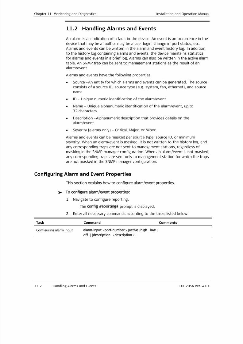
7/25/2019 Manual ETX-205A
http://slidepdf.com/reader/full/manual-etx-205a 306/409
Chapter 11 Monitoring and Diagnostics Installation and Operation Manual
11-2 Handling Alarms and Events ETX-205A Ver. 4.01
11.2 Handling Alarms and Events
An alarm is an indication of a fault in the device. An event is an occurrence in the
device that may be a fault or may be a user login, change in port status, etc.
Alarms and events can be written in the alarm and event history log. In addition
to the history log containing alarms and events, the device maintains statistics
for alarms and events in a brief log. Alarms can also be written in the active alarmtable. An SNMP trap can be sent to management stations as the result of an
alarm/event.
Alarms and events have the following properties:
• Source –An entity for which alarms and events can be generated. The source
consists of a source ID, source type (e.g. system, fan, ethernet), and source
name.
• ID – Unique numeric identification of the alarm/event
• Name – Unique alphanumeric identification of the alarm/event, up to
32 characters
• Description –Alphanumeric description that provides details on the
alarm/event
• Severity (alarms only) – Critical, Major, or Minor.
Alarms and events can be masked per source type, source ID, or minimum
severity. When an alarm/event is masked, it is not written to the history log, and
any corresponding traps are not sent to management stations, regardless of
masking in the SNMP manager configuration. When an alarm/event is not masked,
any corresponding traps are sent only to management station for which the traps
are not masked in the SNMP manager configuration.
Configuring Alarm and Event Properties
This section explains how to configure alarm/event properties.
To configure alarm/event properties:
1. Navigate to configure reporting.
The config>reporting prompt is displayed.
2. Enter all necessary commands according to the tasks listed below.
Task Command Comments
Configuring alarm input alarm-input <port-number> [active high | low|
off] [description <description>]
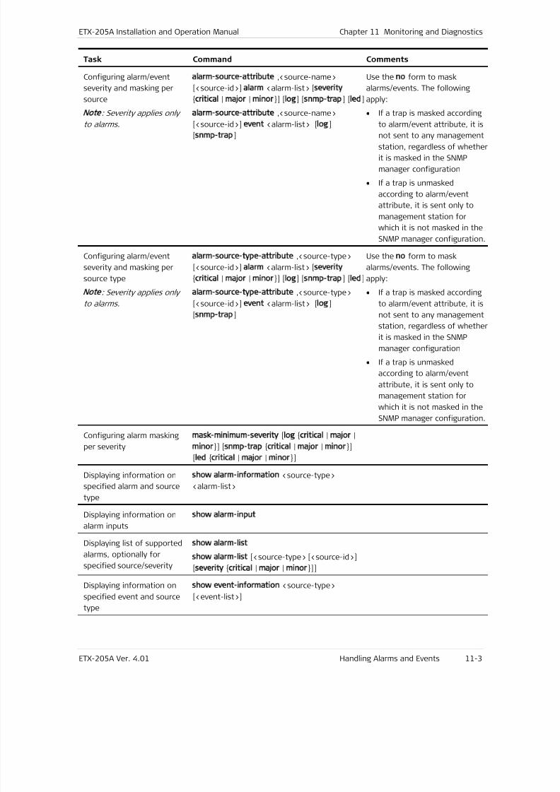
7/25/2019 Manual ETX-205A
http://slidepdf.com/reader/full/manual-etx-205a 307/409
ETX-205A Installation and Operation Manual Chapter 11 Monitoring and Diagnostics
ETX-205A Ver. 4.01 Handling Alarms and Events 11-3
Task Command Comments
Configuring alarm/event
severity and masking per
source
Note
: Severity applies only
to alarms.
alarm-source-attribute ,<source-name>
[<source-id>] alarm <alarm-list> [severity
critical | major | minor] [log] [snmp-trap] [led]
alarm-source-attribute ,<source-name>
[<source-id>] event <alarm-list> [log]
[snmp-trap]
Use the no form to mask
alarms/events. The following
apply:
• If a trap is masked according
to alarm/event attribute, it is
not sent to any management
station, regardless of whether
it is masked in the SNMP
manager configuration
• If a trap is unmasked
according to alarm/event
attribute, it is sent only to
management station for
which it is not masked in the
SNMP manager configuration.
Configuring alarm/event
severity and masking per
source type
Note
: Severity applies only
to alarms.
alarm-source-type-attribute ,<source-type>
[<source-id>] alarm <alarm-list> [severity
critical | major | minor] [log] [snmp-trap] [led]
alarm-source-type-attribute ,<source-type>
[<source-id>] event <alarm-list> [log]
[snmp-trap]
Use the no form to mask
alarms/events. The following
apply:
• If a trap is masked according
to alarm/event attribute, it is
not sent to any management
station, regardless of whether
it is masked in the SNMP
manager configuration
• If a trap is unmasked
according to alarm/event
attribute, it is sent only to
management station forwhich it is not masked in the
SNMP manager configuration.
Configuring alarm masking
per severity
mask-minimum-severity [log critical | major|
minor] [snmp-trap critical | major| minor]
[led critical | major| minor]
Displaying information on
specified alarm and source
type
show alarm-information <source-type>
<alarm-list>
Displaying information on
alarm inputs
show alarm-input
Displaying list of supported
alarms, optionally for
specified source/severity
show alarm-list
show alarm-list [<source-type> [<source-id>]
[severity critical | major| minor]]
Displaying information on
specified event and source
type
show event-information <source-type>
[<event-list>]
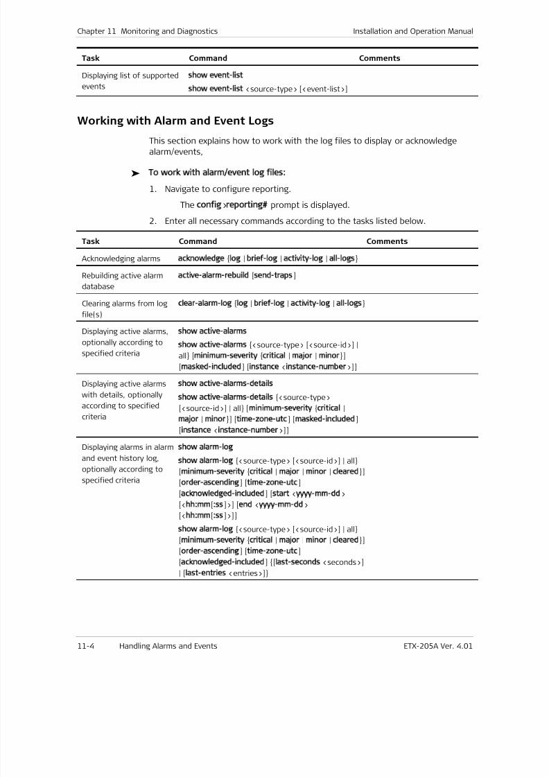
7/25/2019 Manual ETX-205A
http://slidepdf.com/reader/full/manual-etx-205a 308/409
Chapter 11 Monitoring and Diagnostics Installation and Operation Manual
11-4 Handling Alarms and Events ETX-205A Ver. 4.01
Task Command Comments
Displaying list of supported
events
show event-list
show event-list <source-type> [<event-list>]
Working with Alarm and Event Logs
This section explains how to work with the log files to display or acknowledge
alarm/events,
To work with alarm/event log files:
1. Navigate to configure reporting.
The config>reporting prompt is displayed.
2. Enter all necessary commands according to the tasks listed below.
Task Command Comments
Acknowledging alarms acknowledge log | brief-log| activity-log| all-logs
Rebuilding active alarm
database
active-alarm-rebuild [send-traps]
Clearing alarms from log
file(s)
clear-alarm-log log | brief-log| activity-log| all-logs
Displaying active alarms,
optionally according to
specified criteria
show active-alarms
show active-alarms <source-type> [<source-id>] |
all [minimum-severity critical | major| minor]
[masked-included] [instance <instance-number>]]
Displaying active alarmswith details, optionally
according to specified
criteria
show active-alarms-details
show active-alarms-details <source-type>
[<source-id>] | all [minimum-severity critical |
major | minor] [time-zone-utc] [masked-included]
[instance <instance-number>]]
Displaying alarms in alarm
and event history log,
optionally according to
specified criteria
show alarm-log
show alarm-log <source-type> [<source-id>] | all
[minimum-severity critical | major| minor| cleared]
[order-ascending] [time-zone-utc]
[acknowledged-included] [start <yyyy-mm-dd>
[<hh:mm[:ss]>] [end <yyyy-mm-dd>
[<hh:mm[:ss]>]]show alarm-log <source-type> [<source-id>] | all
[minimum-severity critical | major| minor| cleared]
[order-ascending] [time-zone-utc]
[acknowledged-included] [last-seconds <seconds>]
| [last-entries <entries>]
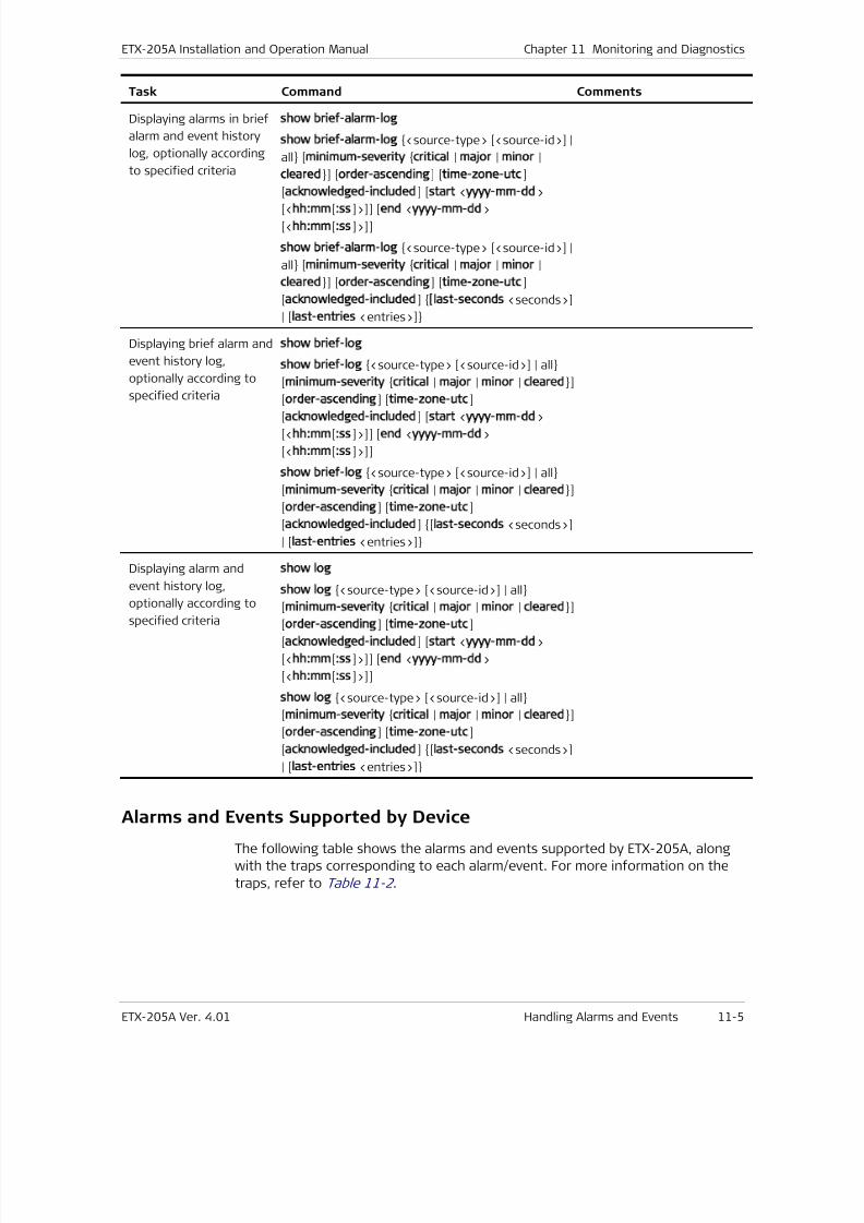
7/25/2019 Manual ETX-205A
http://slidepdf.com/reader/full/manual-etx-205a 309/409
ETX-205A Installation and Operation Manual Chapter 11 Monitoring and Diagnostics
ETX-205A Ver. 4.01 Handling Alarms and Events 11-5
Task Command Comments
Displaying alarms in brief
alarm and event history
log, optionally according
to specified criteria
show brief-alarm-log
show brief-alarm-log <source-type> [<source-id>] |
all [minimum-severity critical | major| minor|
cleared] [order-ascending] [time-zone-utc]
[acknowledged-included] [start <yyyy-mm-dd>
[<hh:mm[:ss]>]] [end <yyyy-mm-dd>
[<hh:mm[:ss]>]]
show brief-alarm-log <source-type> [<source-id>] |
all [minimum-severity critical | major| minor|
cleared] [order-ascending] [time-zone-utc]
[acknowledged-included] [last-seconds <seconds>]
| [last-entries <entries>]
Displaying brief alarm and
event history log,
optionally according to
specified criteria
show brief-log
show brief-log <source-type> [<source-id>] | all
[minimum-severity critical | major| minor| cleared]
[order-ascending] [time-zone-utc]
[acknowledged-included] [start <yyyy-mm-dd>
[<hh:mm[:ss]>]] [end <yyyy-mm-dd>
[<hh:mm[:ss]>]]
show brief-log <source-type> [<source-id>] | all
[minimum-severity critical | major| minor| cleared]
[order-ascending] [time-zone-utc]
[acknowledged-included] [last-seconds <seconds>]
| [last-entries <entries>]
Displaying alarm and
event history log,
optionally according to
specified criteria
show log
show log <source-type> [<source-id>] | all
[minimum-severity critical | major| minor| cleared] [order-ascending] [time-zone-utc]
[acknowledged-included] [start <yyyy-mm-dd>
[<hh:mm[:ss]>]] [end <yyyy-mm-dd>
[<hh:mm[:ss]>]]
show log <source-type> [<source-id>] | all
[minimum-severity critical | major| minor| cleared]
[order-ascending] [time-zone-utc]
[acknowledged-included] [last-seconds <seconds>]
| [last-entries <entries>]
Alarms and Events Supported by Device
The following table shows the alarms and events supported by ETX-205A, along
with the traps corresponding to each alarm/event. For more information on the
traps, refer to Table 11-2 .
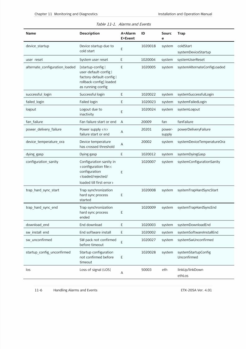
7/25/2019 Manual ETX-205A
http://slidepdf.com/reader/full/manual-etx-205a 310/409
Chapter 11 Monitoring and Diagnostics Installation and Operation Manual
11-6 Handling Alarms and Events ETX-205A Ver. 4.01
Table 11-1. Alarms and Events
Name Description A=Alarm
E=Event
ID Sourc
e
Trap
device _ startup Device startup due to
cold startE
1020018 system coldStart
systemDeviceStartup
user _
reset System user reset E 1020004 system systemUserReset
alternate _ configuration _ loaded startup-config |
user-default-config |
factory-default-config |
rollback-config loaded
as running-config
E 1020005 system systemAlternateConfigLoaded
successful _ login Successful login E 1020022 system systemSuccessfulLogin
failed _ login Failed login E 1020023 system systemFailedLogin
logout Logout due to
inactivity
E1020024 system systemLogout
fan _ failure Fan failure start or end A 20009 fan fanFailure
power _ delivery _ failure Power supply <n>
failure start or endA
20201 power-
supply
powerDeliveryFailure
device _ temperature _ ora Device temperature
has crossed thresholdA
20002 system systemDeviceTemperatureOra
dying _ gasp Dying gasp E 1020012 system systemDyingGasp
configuration _ sanity Configuration sanity in
<configuration file>:
configuration
<loaded/rejected/
loaded till first error>
E
1020007 system systemConfigurationSanity
trap _ hard _ sync _ start Trap synchronization
hard sync process
started
E
1020008 system systemTrapHardSyncStart
trap _ hard _ sync _ end Trap synchronization
hard sync process
ended
E
1020009 system systemTrapHardSyncEnd
download _ end End download E 1020003 system systemDownloadEnd
sw _ install _ end End software install E 1020002
system systemSoftwareInstallEnd
sw _ unconfirmed SW pack not confirmed
before timeoutE
1020027 system systemSwUnconfirmed
startup _ config _ unconfirmed Startup configuration
not confirmed before
timeout
E
1020028 system systemStartupConfig
Unconfirmed
los Loss of signal (LOS)A
50003 eth linkUp/linkDown
ethLos
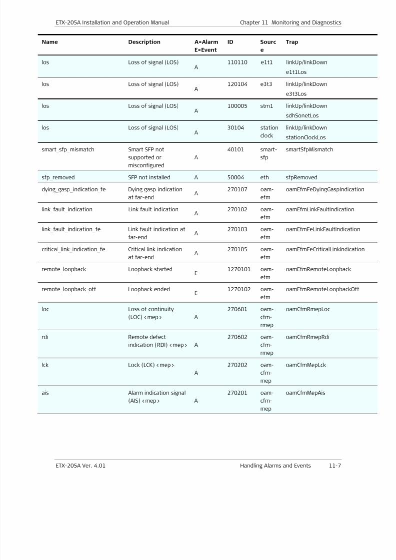
7/25/2019 Manual ETX-205A
http://slidepdf.com/reader/full/manual-etx-205a 311/409
ETX-205A Installation and Operation Manual Chapter 11 Monitoring and Diagnostics
ETX-205A Ver. 4.01 Handling Alarms and Events 11-7
Name Description A=Alarm
E=Event
ID Sourc
e
Trap
los Loss of signal (LOS)A
110110 e1t1 linkUp/linkDown
e1t1Los
los Loss of signal (LOS)A
120104 e3t3 linkUp/linkDown
e3t3Los
los Loss of signal (LOS)A
100005 stm1 linkUp/linkDown
sdhSonetLos
los Loss of signal (LOS)A
30104 station
clock
linkUp/linkDown
stationClockLos
smart _ sfp _ mismatch Smart SFP not
supported or
misconfigured
A
40101 smart-
sfp
smartSfpMismatch
sfp _ removed SFP not installed A 50004 eth sfpRemoved
dying _ gasp _ indication _ fe Dying gasp indication
at far-endA
270107 oam-
efm
oamEfmFeDyingGaspIndicatio
link _ fault _ indication Link fault indicationA
270102 oam-
efm
oamEfmLinkFaultIndication
link _ fault _ indication _ fe Link fault indication at
far-endA
270103 oam-
efm
oamEfmFeLinkFaultIndication
critical _ link _ indication _ fe Critical link indication
at far-endA
270105 oam-
efm
oamEfmFeCriticalLinkIndicatio
remote _ loopback Loopback startedE
1270101 oam-
efm
oamEfmRemoteLoopback
remote _ loopback _ off Loopback endedE
1270102 oam-
efm
oamEfmRemoteLoopbackOff
loc Loss of continuity
(LOC) <mep> A
270601 oam-
cfm-
rmep
oamCfmRmepLoc
rdi Remote defect
indication (RDI) <mep> A
270602 oam-
cfm-
rmep
oamCfmRmepRdi
lck Lock (LCK) <mep>
A
270202 oam-
cfm-mep
oamCfmMepLck
ais Alarm indication signal
(AIS) <mep> A
270201 oam-
cfm-
mep
oamCfmMepAis
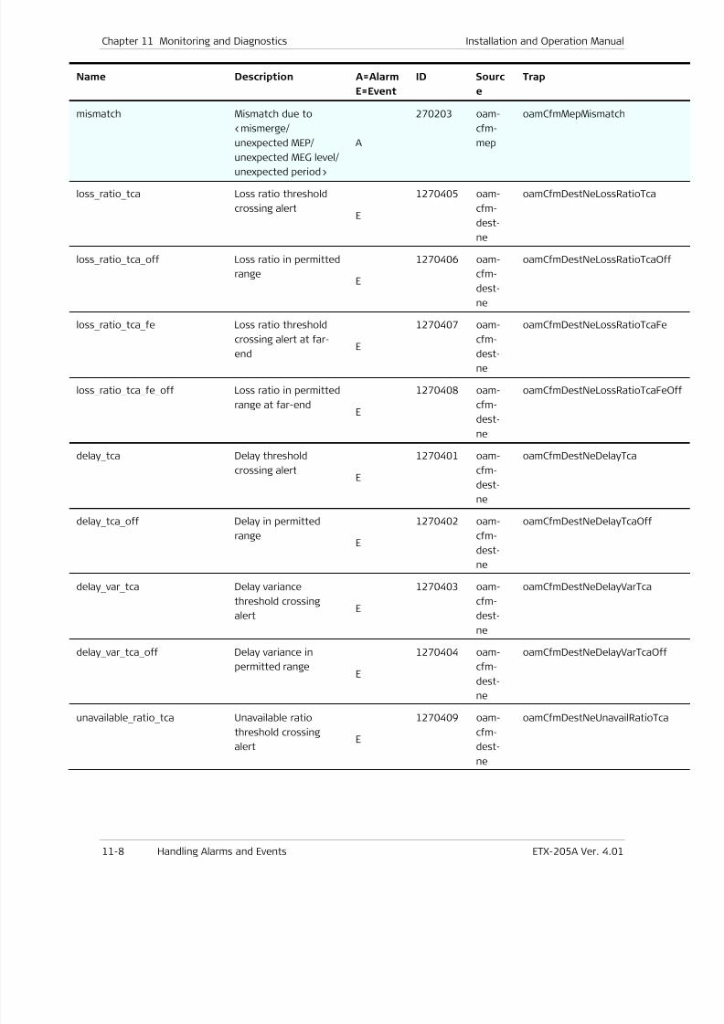
7/25/2019 Manual ETX-205A
http://slidepdf.com/reader/full/manual-etx-205a 312/409
Chapter 11 Monitoring and Diagnostics Installation and Operation Manual
11-8 Handling Alarms and Events ETX-205A Ver. 4.01
Name Description A=Alarm
E=Event
ID Sourc
e
Trap
mismatch Mismatch due to
<mismerge/
unexpected MEP/
unexpected MEG level/
unexpected period>
A
270203 oam-
cfm-
mep
oamCfmMepMismatch
loss _ ratio _ tca Loss ratio threshold
crossing alertE
1270405 oam-
cfm-
dest-
ne
oamCfmDestNeLossRatioTca
loss _ ratio _ tca _ off Loss ratio in permitted
rangeE
1270406 oam-
cfm-
dest-
ne
oamCfmDestNeLossRatioTcaO
loss _ ratio _ tca _ fe Loss ratio threshold
crossing alert at far-end
E
1270407 oam-
cfm-dest-
ne
oamCfmDestNeLossRatioTcaF
loss _ ratio _ tca _ fe _ off Loss ratio in permitted
range at far-endE
1270408 oam-
cfm-
dest-
ne
oamCfmDestNeLossRatioTcaF
delay _ tca Delay threshold
crossing alertE
1270401 oam-
cfm-
dest-
ne
oamCfmDestNeDelayTca
delay _ tca _ off Delay in permitted
rangeE
1270402 oam-
cfm-
dest-
ne
oamCfmDestNeDelayTcaOff
delay _ var _ tca Delay variance
threshold crossing
alertE
1270403 oam-
cfm-
dest-
ne
oamCfmDestNeDelayVarTca
delay _ var _ tca _ off Delay variance in
permitted rangeE
1270404 oam-
cfm-
dest-ne
oamCfmDestNeDelayVarTcaOf
unavailable _ ratio _ tca Unavailable ratio
threshold crossing
alertE
1270409 oam-
cfm-
dest-
ne
oamCfmDestNeUnavailRatioTc
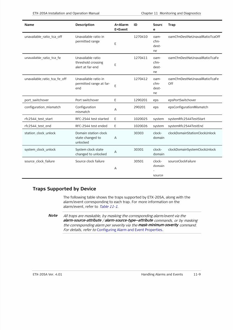
7/25/2019 Manual ETX-205A
http://slidepdf.com/reader/full/manual-etx-205a 313/409
ETX-205A Installation and Operation Manual Chapter 11 Monitoring and Diagnostics
ETX-205A Ver. 4.01 Handling Alarms and Events 11-9
Name Description A=Alarm
E=Event
ID Sourc
e
Trap
unavailable _ ratio _ tca _ off Unavailable ratio in
permitted rangeE
1270410 oam-
cfm-
dest-
ne
oamCfmDestNeUnavailRatioTc
unavailable _ ratio _ tca _ fe Unavailable ratio
threshold crossing
alert at far-endE
1270411 oam-
cfm-
dest-
ne
oamCfmDestNeUnavailRatioTc
unavailable_ratio _ tca _ fe _ off Unavailable ratio in
permitted range at far-
endE
1270412 oam-
cfm-
dest-
ne
oamCfmDestNeUnavailRatioTc
Off
port _ switchover Port switchover E 1290201 eps epsPortSwitchover
configuration _ mismatch Configuration
mismatch A290201 eps epsConfigurationMismatch
rfc2544 _ test _ start RFC-2544 test started E 1020025 system systemRfc2544TestStart
rfc2544 _ test _ end RFC-2544 test ended E 1020026 system systemRfc2544TestEnd
station _ clock _ unlock Domain station clock
state changed to
unlocked
A
30303 clock-
domain
clockDomainStationClockUnloc
system _ clock _ unlock System clock state
changed to unlockedA
30301 clock-
domain
clockDomainSystemClockUnlo
source _ clock _ failure Source clock failure
A
30501 clock-
domain
-
source
sourceClockFailure
Traps Supported by Device
The following table shows the traps supported by ETX-205A, along with the
alarm/event corresponding to each trap. For more information on the
alarm/event, refer to Table 11-1.
All traps are maskable, by masking the corresponding alarm/event via the
alarm source attribute / alarm source type—attribute commands, or by maskingthe corresponding alarm per severity via the mask minimum severity command.
For details, refer to Configuring Alarm and Event Properties.
Note
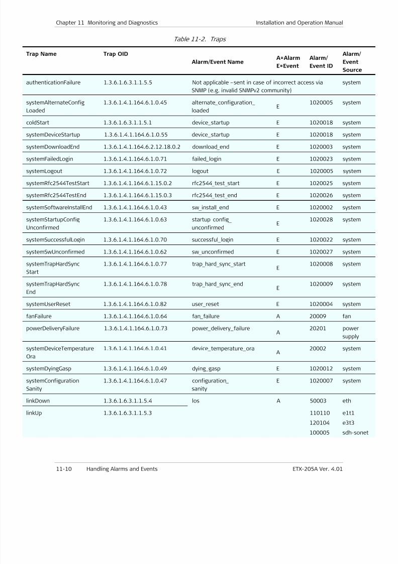
7/25/2019 Manual ETX-205A
http://slidepdf.com/reader/full/manual-etx-205a 314/409
Chapter 11 Monitoring and Diagnostics Installation and Operation Manual
11-10 Handling Alarms and Events ETX-205A Ver. 4.01
Table 11-2. Traps
Trap Name Trap OID
Alarm/Event NameA=Alarm
E=Event
Alarm/
Event ID
Alarm/
Event
Source
authenticationFailure 1.3.6.1.6.3.1.1.5.5 Not applicable –sent in case of incorrect access via
SNMP (e.g. invalid SNMPv2 community)
system
systemAlternateConfig
Loaded
1.3.6.1.4.1.164.6.1.0.45 alternate _configuration _
loadedE
1020005 system
coldStart 1.3.6.1.6.3.1.1.5.1 device _startup E 1020018 system
systemDeviceStartup 1.3.6.1.4.1.164.6.1.0.55 device _startup E 1020018 system
systemDownloadEnd 1.3.6.1.4.1.164.6.2.12.18.0.2 download _ end E 1020003 system
systemFailedLogin 1.3.6.1.4.1.164.6.1.0.71 failed _login E 1020023 system
systemLogout 1.3.6.1.4.1.164.6.1.0.72 logout E 1020005 system
systemRfc2544TestStart 1.3.6.1.4.1.164.6.1.15.0.2 rfc2544 _ test _ start E 1020025 system
systemRfc2544TestEnd 1.3.6.1.4.1.164.6.1.15.0.3 rfc2544 _ test _ end E 1020026 system
systemSoftwareInstallEnd 1.3.6.1.4.1.164.6.1.0.43 sw _ install _ end E 1020002 system
systemStartupConfig
Unconfirmed
1.3.6.1.4.1.164.6.1.0.63 startup _ config _
unconfirmedE
1020028 system
systemSuccessfulLogin 1.3.6.1.4.1.164.6.1.0.70 successful _login E 1020022 system
systemSwUnconfirmed 1.3.6.1.4.1.164.6.1.0.62 sw _ unconfirmed E 1020027 system
systemTrapHardSync
Start
1.3.6.1.4.1.164.6.1.0.77 trap _ hard _ sync _ startE
1020008 system
systemTrapHardSync
End
1.3.6.1.4.1.164.6.1.0.78 trap _ hard _ sync _ endE
1020009
system
systemUserReset 1.3.6.1.4.1.164.6.1.0.82 user _reset E 1020004 system
fanFailure 1.3.6.1.4.1.164.6.1.0.64 fan _failure A 20009 fan
powerDeliveryFailure 1.3.6.1.4.1.164.6.1.0.73 power _delivery _failureA
20201 power
supply
systemDeviceTemperature
Ora
1.3.6.1.4.1.164.6.1.0.41 device _temperature _oraA
20002 system
systemDyingGasp 1.3.6.1.4.1.164.6.1.0.49 dying _gasp E 1020012 system
systemConfiguration
Sanity
1.3.6.1.4.1.164.6.1.0.47 configuration _
sanity
E 1020007 system
linkDown 1.3.6.1.6.3.1.1.5.4 los A 50003 eth
linkUp 1.3.6.1.6.3.1.1.5.3 110110
120104
100005
e1t1
e3t3
sdh-son
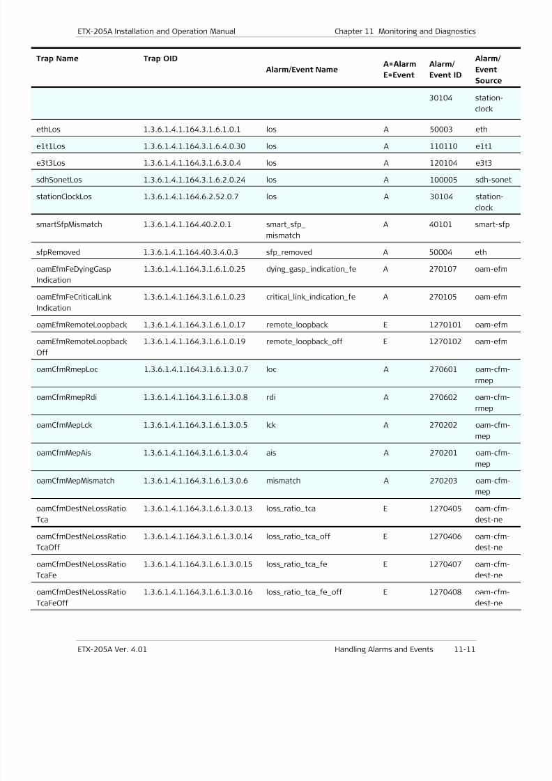
7/25/2019 Manual ETX-205A
http://slidepdf.com/reader/full/manual-etx-205a 315/409
ETX-205A Installation and Operation Manual Chapter 11 Monitoring and Diagnostics
ETX-205A Ver. 4.01 Handling Alarms and Events 11-11
Trap Name Trap OID
Alarm/Event NameA=Alarm
E=Event
Alarm/
Event ID
Alarm/
Event
Source
30104 station-
clock
ethLos 1.3.6.1.4.1.164.3.1.6.1.0.1 los A 50003 eth
e1t1Los 1.3.6.1.4.1.164.3.1.6.4.0.30 los A 110110 e1t1
e3t3Los 1.3.6.1.4.1.164.3.1.6.3.0.4 los A 120104 e3t3
sdhSonetLos 1.3.6.1.4.1.164.3.1.6.2.0.24 los A 100005 sdh-son
stationClockLos 1.3.6.1.4.1.164.6.2.52.0.7 los A 30104 station-
clock
smartSfpMismatch 1.3.6.1.4.1.164.40.2.0.1 smart _sfp _
mismatch
A 40101 smart-sf
sfpRemoved 1.3.6.1.4.1.164.40.3.4.0.3 sfp _removed A 50004 eth
oamEfmFeDyingGasp
Indication
1.3.6.1.4.1.164.3.1.6.1.0.25 dying _gasp _indication _fe A 270107 oam-efm
oamEfmFeCriticalLink
Indication
1.3.6.1.4.1.164.3.1.6.1.0.23 critical _link _indication _fe A 270105 oam-efm
oamEfmRemoteLoopback 1.3.6.1.4.1.164.3.1.6.1.0.17 remote _loopback E 1270101 oam-efm
oamEfmRemoteLoopback
Off
1.3.6.1.4.1.164.3.1.6.1.0.19 remote _loopback _off E 1270102 oam-efm
oamCfmRmepLoc 1.3.6.1.4.1.164.3.1.6.1.3.0.7 loc A 270601 oam-cfm
rmep
oamCfmRmepRdi 1.3.6.1.4.1.164.3.1.6.1.3.0.8 rdi A 270602 oam-cfm
rmep
oamCfmMepLck 1.3.6.1.4.1.164.3.1.6.1.3.0.5 lck A 270202 oam-cfm
mep
oamCfmMepAis 1.3.6.1.4.1.164.3.1.6.1.3.0.4 ais A 270201 oam-cfm
mep
oamCfmMepMismatch 1.3.6.1.4.1.164.3.1.6.1.3.0.6 mismatch A 270203 oam-cfm
mep
oamCfmDestNeLossRatio
Tca
1.3.6.1.4.1.164.3.1.6.1.3.0.13 loss _ratio _tca E 1270405 oam-cfm
dest-ne
oamCfmDestNeLossRatio
TcaOff
1.3.6.1.4.1.164.3.1.6.1.3.0.14 loss _ratio _tca _off E 1270406 oam-cfm
dest-ne
oamCfmDestNeLossRatio
TcaFe
1.3.6.1.4.1.164.3.1.6.1.3.0.15 loss _ratio _tca _fe E 1270407 oam-cfm
dest-ne
oamCfmDestNeLossRatio
TcaFeOff
1.3.6.1.4.1.164.3.1.6.1.3.0.16 loss _ratio _tca _fe _off E 1270408 oam-cfm
dest-ne
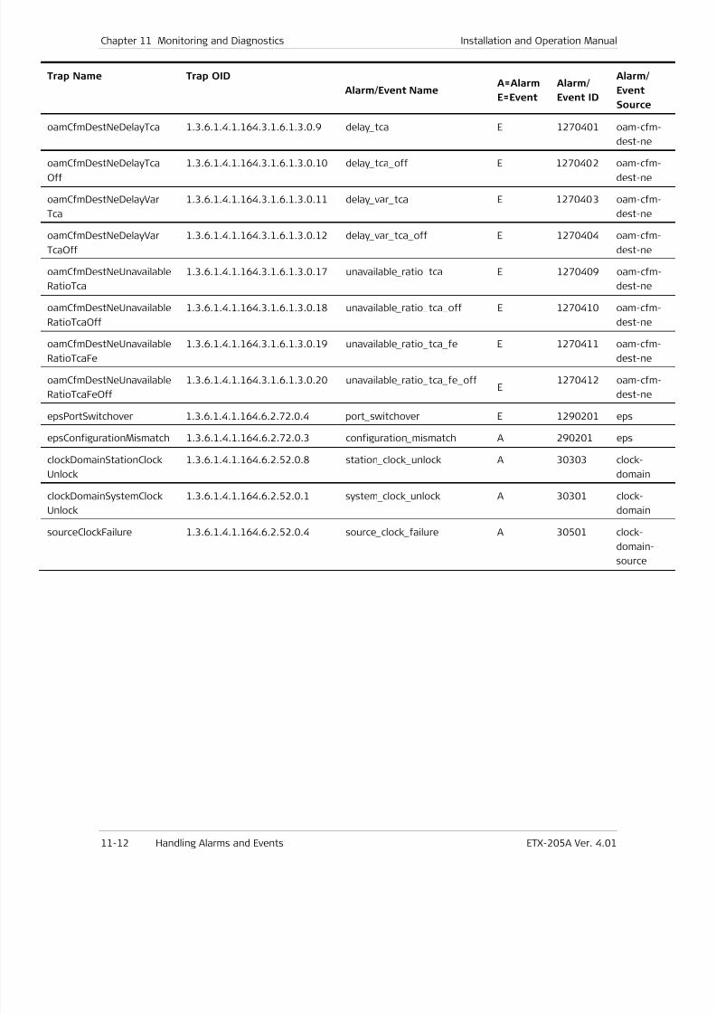
7/25/2019 Manual ETX-205A
http://slidepdf.com/reader/full/manual-etx-205a 316/409
Chapter 11 Monitoring and Diagnostics Installation and Operation Manual
11-12 Handling Alarms and Events ETX-205A Ver. 4.01
Trap Name Trap OID
Alarm/Event NameA=Alarm
E=Event
Alarm/
Event ID
Alarm/
Event
Source
oamCfmDestNeDelayTca 1.3.6.1.4.1.164.3.1.6.1.3.0.9 delay _tca E 1270401 oam-cfm
dest-ne
oamCfmDestNeDelayTcaOff 1.3.6.1.4.1.164.3.1.6.1.3.0.10 delay _
tca _
off E 1270402 oam-cfmdest-ne
oamCfmDestNeDelayVar
Tca
1.3.6.1.4.1.164.3.1.6.1.3.0.11 delay _var _tca E 1270403 oam-cfm
dest-ne
oamCfmDestNeDelayVar
TcaOff
1.3.6.1.4.1.164.3.1.6.1.3.0.12 delay _var _tca _off E 1270404 oam-cfm
dest-ne
oamCfmDestNeUnavailable
RatioTca
1.3.6.1.4.1.164.3.1.6.1.3.0.17 unavailable _ratio _tca E 1270409 oam-cfm
dest-ne
oamCfmDestNeUnavailable
RatioTcaOff
1.3.6.1.4.1.164.3.1.6.1.3.0.18 unavailable _ratio _tca _off E 1270410 oam-cfm
dest-ne
oamCfmDestNeUnavailable
RatioTcaFe
1.3.6.1.4.1.164.3.1.6.1.3.0.19 unavailable _ratio _tca _fe E 1270411 oam-cfm
dest-ne
oamCfmDestNeUnavailable
RatioTcaFeOff
1.3.6.1.4.1.164.3.1.6.1.3.0.20 unavailable _ratio _tca _fe _offE
1270412 oam-cfm
dest-ne
epsPortSwitchover 1.3.6.1.4.1.164.6.2.72.0.4 port _switchover E 1290201 eps
epsConfigurationMismatch 1.3.6.1.4.1.164.6.2.72.0.3 configuration _mismatch A 290201 eps
clockDomainStationClock
Unlock
1.3.6.1.4.1.164.6.2.52.0.8 station _clock _unlock A 30303 clock-
domain
clockDomainSystemClock
Unlock
1.3.6.1.4.1.164.6.2.52.0.1 system _ clock _ unlock A 30301 clock-
domain
sourceClockFailure 1.3.6.1.4.1.164.6.2.52.0.4 source _clock _failure A 30501 clock-
domain-
source
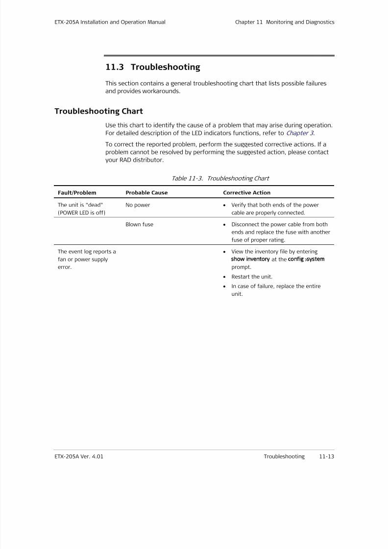
7/25/2019 Manual ETX-205A
http://slidepdf.com/reader/full/manual-etx-205a 317/409
ETX-205A Installation and Operation Manual Chapter 11 Monitoring and Diagnostics
ETX-205A Ver. 4.01 Troubleshooting 11-13
11.3 Troubleshooting
This section contains a general troubleshooting chart that lists possible failures
and provides workarounds.
Troubleshooting Chart
Use this chart to identify the cause of a problem that may arise during operation.
For detailed description of the LED indicators functions, refer to Chapter 3 .
To correct the reported problem, perform the suggested corrective actions. If a
problem cannot be resolved by performing the suggested action, please contact
your RAD distributor.
Table 11-3. Troubleshooting Chart
Fault/Problem Probable Cause Corrective Action
The unit is “dead”
(POWER LED is off)
No power • Verify that both ends of the power
cable are properly connected.
Blown fuse • Disconnect the power cable from both
ends and replace the fuse with another
fuse of proper rating.
The event log reports a
fan or power supply
error.
• View the inventory file by entering
show inventory at the config>system
prompt.
•
Restart the unit.
• In case of failure, replace the entire
unit.
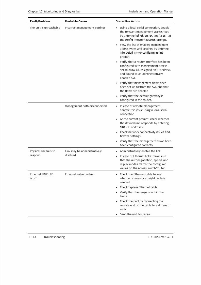
7/25/2019 Manual ETX-205A
http://slidepdf.com/reader/full/manual-etx-205a 318/409
7/25/2019 Manual ETX-205A
http://slidepdf.com/reader/full/manual-etx-205a 319/409
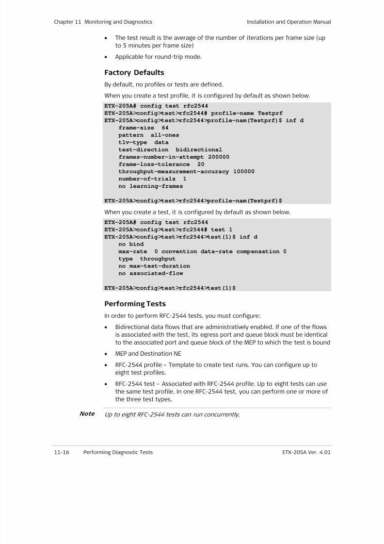
7/25/2019 Manual ETX-205A
http://slidepdf.com/reader/full/manual-etx-205a 320/409
Chapter 11 Monitoring and Diagnostics Installation and Operation Manual
11-16 Performing Diagnostic Tests ETX-205A Ver. 4.01
• The test result is the average of the number of iterations per frame size (up
to 5 minutes per frame size)
• Applicable for round-trip mode.
Factory Defaults
By default, no profiles or tests are defined.
When you create a test profile, it is configured by default as shown below.
ETX-205A# config test rfc2544
ETX-205A >config>test>rfc2544# profile-name Testprf
ETX-205A >config>test>rfc2544> profile-nam(Testprf)$ inf d
frame-size 64
pattern all-ones
tlv-type data
test-direction bidirectional
frames-number-in-attempt 200000
frame-loss-tolerance 20
throughput-measurement-accuracy 100000
number-of-trials 1no learning-frames
ETX-205A >config>test>rfc2544> profile-nam(Testprf)$
When you create a test, it is configured by default as shown below.
ETX-205A# config test rfc2544
ETX-205A >config>test>rfc2544# test 1
ETX-205A >config>test>rfc2544>test(1)$ inf d
no bind
max-rate 0 convention data-rate compensation 0
type throughput
no max-test-duration
no associated-flow
ETX-205A >config>test>rfc2544>test(1)$
Performing Tests
In order to perform RFC-2544 tests, you must configure:
• Bidirectional data flows that are administratively enabled. If one of the flows
is associated with the test, its egress port and queue block must be identical
to the associated port and queue block of the MEP to which the test is bound
• MEP and Destination NE
•
RFC-2544 profile – Template to create test runs. You can configure up to
eight test profiles.
• RFC-2544 test – Associated with RFC-2544 profile. Up to eight tests can use
the same test profile. In one RFC-2544 test, you can perform one or more of
the three test types.
Up to eight RFC-2544 tests can run concurrently.Note
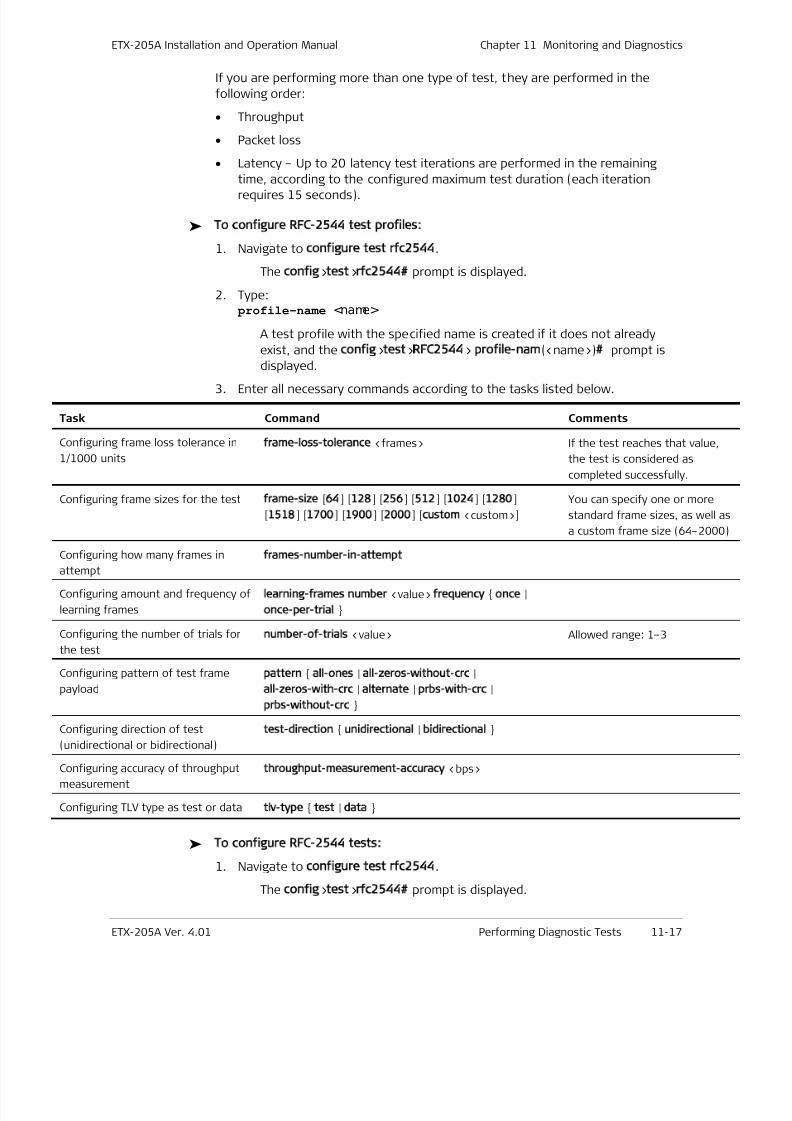
7/25/2019 Manual ETX-205A
http://slidepdf.com/reader/full/manual-etx-205a 321/409
ETX-205A Installation and Operation Manual Chapter 11 Monitoring and Diagnostics
ETX-205A Ver. 4.01 Performing Diagnostic Tests 11-17
If you are performing more than one type of test, they are performed in the
following order:
• Throughput
• Packet loss
• Latency – Up to 20 latency test iterations are performed in the remaining
time, according to the configured maximum test duration (each iteration
requires 15 seconds).
To configure RFC-2544 test profiles:
1. Navigate to configure test rfc2544.
The config>test>rfc2544 prompt is displayed.
2. Type: profile-name <name>
A test profile with the specified name is created if it does not already
exist, and the config>test>RFC2544> profile-nam(<name>) prompt is
displayed.
3. Enter all necessary commands according to the tasks listed below.
Task Command Comments
Configuring frame loss tolerance in
1/1000 units
frame-loss-tolerance <frames> If the test reaches that value,
the test is considered as
completed successfully.
Configuring frame sizes for the test frame-size [64] [128] [256] [512] [1024] [1280]
[1518] [1700] [1900] [2000] [custom <custom>]
You can specify one or more
standard frame sizes, as well a
a custom frame size (64–2000
Configuring how many frames inattempt
frames-number-in-attempt
Configuring amount and frequency of
learning frames
learning-frames number <value> frequency once |
once-per-trial
Configuring the number of trials for
the test
number-of-trials <value> Allowed range: 1–3
Configuring pattern of test frame
payload
pattern all-ones | all-zeros-without-crc |
all-zeros-with-crc | alternate | prbs-with-crc |
prbs-without-crc
Configuring direction of test
(unidirectional or bidirectional)
test-direction unidirectional | bidirectional
Configuring accuracy of throughput
measurement
throughput-measurement-accuracy <bps>
Configuring TLV type as test or datatlv-type test | data
To configure RFC-2544 tests:
1. Navigate to configure test rfc2544.
The config>test>rfc2544 prompt is displayed.
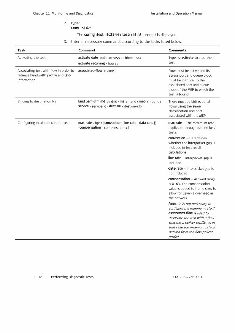
7/25/2019 Manual ETX-205A
http://slidepdf.com/reader/full/manual-etx-205a 322/409
Chapter 11 Monitoring and Diagnostics Installation and Operation Manual
11-18 Performing Diagnostic Tests ETX-205A Ver. 4.01
2. Type:test <i d>
The config>test>rfc2544> test(<id>) prompt is displayed.
3. Enter all necessary commands according to the tasks listed below.
Task Command Comments
Activating the testactivate date <dd-mm-yyyy> <hh:mm:ss>
activate recurring <hours>
Type no activate to stop the
test
Associating test with flow in order to
retrieve bandwidth profile and QoS
information.
associated-flow <name> Flow must be active and its
egress port and queue block
must be identical to the
associated port and queue
block of the MEP to which the
test is bound
Binding to destination NEbind oam-cfm md <md-id> ma <ma-id> mep <mep-id>
service <service-id> dest-ne <dest-ne-id>
There must be bidirectional
flows using the same
classification and portassociated with the MEP
Configuring maximum rate for testmax-rate <bps> [convention line-rate | data-rate]
[compensation <compensation>]
max-rate – The maximum rate
applies to throughput and loss
tests.
convention – Determines
whether the interpacket gap is
included in test result
calculations:
line-rate – Interpacket gap is
included
data-rate – Interpacket gap is
not included
compensation – Allowed range
is 0–63. The compensation
value is added to frame size, t
allow for Layer-1 overhead in
the network
Note
: It is not necessary to
configure the maximum rate if
associated flow
is used to
associate the test with a flow
that has a policer profile, as in
that case the maximum rate is
derived from the flow policer
profile.
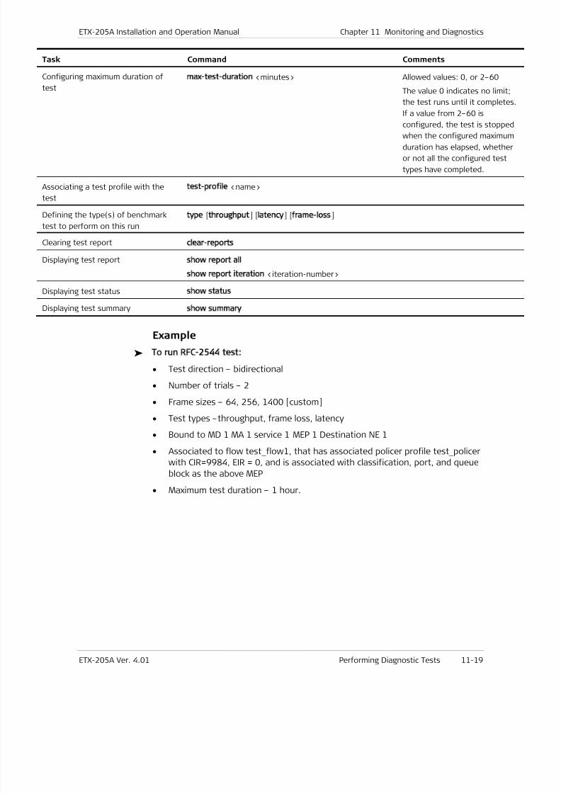
7/25/2019 Manual ETX-205A
http://slidepdf.com/reader/full/manual-etx-205a 323/409
ETX-205A Installation and Operation Manual Chapter 11 Monitoring and Diagnostics
ETX-205A Ver. 4.01 Performing Diagnostic Tests 11-19
Task Command Comments
Configuring maximum duration of
test
max-test-duration <minutes> Allowed values: 0, or 2–60
The value 0 indicates no limit;
the test runs until it completes
If a value from 2–60 is
configured, the test is stopped
when the configured maximum
duration has elapsed, whether
or not all the configured test
types have completed.
Associating a test profile with the
test
test-profile <name>
Defining the type(s) of benchmark
test to perform on this run
type [throughput] [latency] [frame-loss]
Clearing test reportclear-reports
Displaying test report show report all
show report iteration <iteration-number>
Displaying test status show status
Displaying test summaryshow summary
Example
To run RFC-2544 test:
• Test direction – bidirectional
• Number of trials – 2
• Frame sizes – 64, 256, 1400 [custom]
• Test types –throughput, frame loss, latency
• Bound to MD 1 MA 1 service 1 MEP 1 Destination NE 1
• Associated to flow test _ flow1, that has associated policer profile test _ policer
with CIR=9984, EIR = 0, and is associated with classification, port, and queue
block as the above MEP
• Maximum test duration – 1 hour.
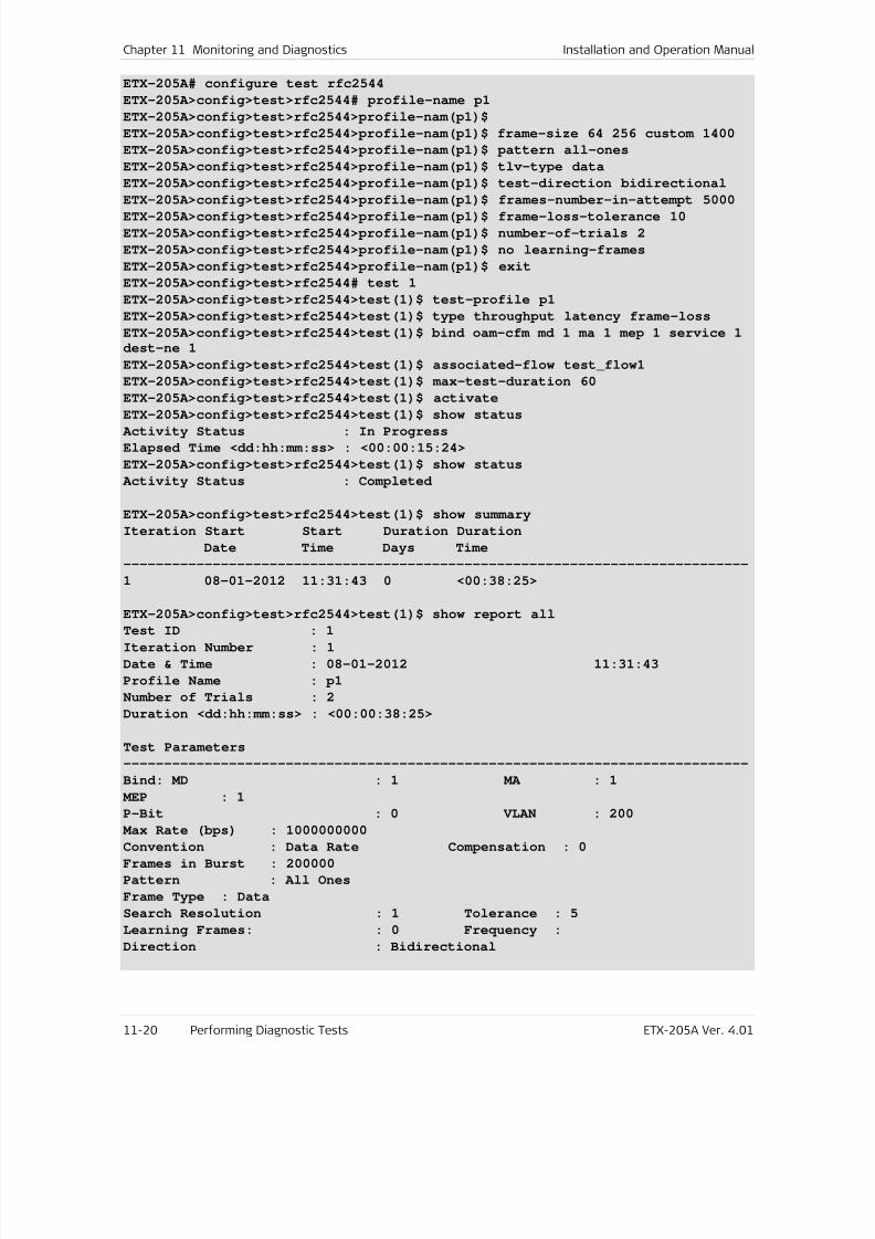
7/25/2019 Manual ETX-205A
http://slidepdf.com/reader/full/manual-etx-205a 324/409
Chapter 11 Monitoring and Diagnostics Installation and Operation Manual
11-20 Performing Diagnostic Tests ETX-205A Ver. 4.01
ETX-205A# configure test rfc2544
ETX-205A>config>test>rfc2544# profile-name p1
ETX-205A>config>test>rfc2544>profile-nam(p1)$
ETX-205A>config>test>rfc2544>profile-nam(p1)$ frame-size 64 256 custom 1400
ETX-205A>config>test>rfc2544>profile-nam(p1)$ pattern all-ones
ETX-205A>config>test>rfc2544>profile-nam(p1)$ tlv-type data
ETX-205A>config>test>rfc2544>profile-nam(p1)$ test-direction bidirectional
ETX-205A>config>test>rfc2544>profile-nam(p1)$ frames-number-in-attempt 5000ETX-205A>config>test>rfc2544>profile-nam(p1)$ frame-loss-tolerance 10
ETX-205A>config>test>rfc2544>profile-nam(p1)$ number-of-trials 2
ETX-205A>config>test>rfc2544>profile-nam(p1)$ no learning-frames
ETX-205A>config>test>rfc2544>profile-nam(p1)$ exit
ETX-205A>config>test>rfc2544# test 1
ETX-205A>config>test>rfc2544>test(1)$ test-profile p1
ETX-205A>config>test>rfc2544>test(1)$ type throughput latency frame-loss
ETX-205A>config>test>rfc2544>test(1)$ bind oam-cfm md 1 ma 1 mep 1 service 1
dest-ne 1
ETX-205A>config>test>rfc2544>test(1)$ associated-flow test_flow1
ETX-205A>config>test>rfc2544>test(1)$ max-test-duration 60
ETX-205A>config>test>rfc2544>test(1)$ activate
ETX-205A>config>test>rfc2544>test(1)$ show status Activity Status : In Progress
Elapsed Time <dd:hh:mm:ss> : <00:00:15:24>
ETX-205A>config>test>rfc2544>test(1)$ show status
Activity Status : Completed
ETX-205A>config>test>rfc2544>test(1)$ show summary
Iteration Start Start Duration Duration
Date Time Days Time
-----------------------------------------------------------------------------
1 08-01-2012 11:31:43 0 <00:38:25>
ETX-205A>config>test>rfc2544>test(1)$ show report allTest ID : 1
Iteration Number : 1
Date & Time : 08-01-2012 11:31:43
Profile Name : p1
Number of Trials : 2
Duration <dd:hh:mm:ss> : <00:00:38:25>
Test Parameters
-----------------------------------------------------------------------------
Bind: MD : 1 MA : 1
MEP : 1
P-Bit : 0 VLAN : 200
Max Rate (bps) : 1000000000
Convention : Data Rate Compensation : 0
Frames in Burst : 200000
Pattern : All Ones
Frame Type : Data
Search Resolution : 1 Tolerance : 5
Learning Frames: : 0 Frequency :
Direction : Bidirectional
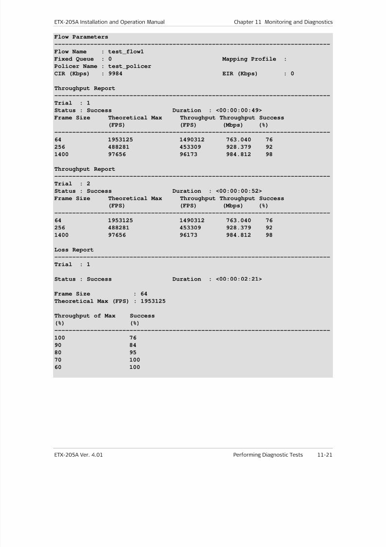
7/25/2019 Manual ETX-205A
http://slidepdf.com/reader/full/manual-etx-205a 325/409
ETX-205A Installation and Operation Manual Chapter 11 Monitoring and Diagnostics
ETX-205A Ver. 4.01 Performing Diagnostic Tests 11-21
Flow Parameters
-----------------------------------------------------------------------------
Flow Name : test_flow1
Fixed Queue : 0 Mapping Profile :
Policer Name : test_policer
CIR (Kbps) : 9984 EIR (Kbps) : 0
Throughput Report-----------------------------------------------------------------------------
Trial : 1
Status : Success Duration : <00:00:00:49>
Frame Size Theoretical Max Throughput Throughput Success
(FPS) (FPS) (Mbps) (%)
-----------------------------------------------------------------------------
64 1953125 1490312 763.040 76
256 488281 453309 928.379 92
1400 97656 96173 984.812 98
Throughput Report
-----------------------------------------------------------------------------
Trial : 2
Status : Success Duration : <00:00:00:52>
Frame Size Theoretical Max Throughput Throughput Success
(FPS) (FPS) (Mbps) (%)
-----------------------------------------------------------------------------
64 1953125 1490312 763.040 76
256 488281 453309 928.379 92
1400 97656 96173 984.812 98
Loss Report
-----------------------------------------------------------------------------
Trial : 1
Status : Success Duration : <00:00:02:21>
Frame Size : 64
Theoretical Max (FPS) : 1953125
Throughput of Max Success
(%) (%)
-----------------------------------------------------------------------------
100 76
90 84
80 95
70 100
60 100
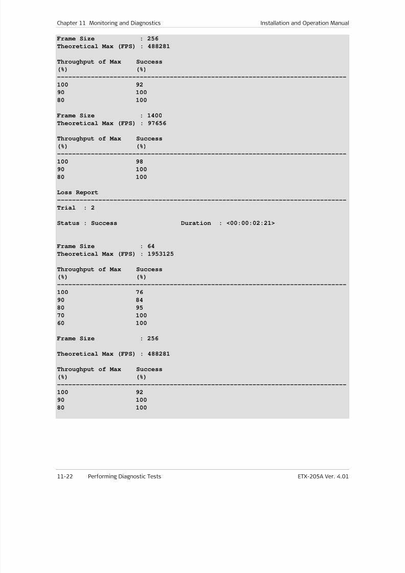
7/25/2019 Manual ETX-205A
http://slidepdf.com/reader/full/manual-etx-205a 326/409
Chapter 11 Monitoring and Diagnostics Installation and Operation Manual
11-22 Performing Diagnostic Tests ETX-205A Ver. 4.01
Frame Size : 256
Theoretical Max (FPS) : 488281
Throughput of Max Success
(%) (%)
-----------------------------------------------------------------------------
100 92
90 10080 100
Frame Size : 1400
Theoretical Max (FPS) : 97656
Throughput of Max Success
(%) (%)
-----------------------------------------------------------------------------
100 98
90 100
80 100
Loss Report
-----------------------------------------------------------------------------
Trial : 2
Status : Success Duration : <00:00:02:21>
Frame Size : 64
Theoretical Max (FPS) : 1953125
Throughput of Max Success
(%) (%)
-----------------------------------------------------------------------------100 76
90 84
80 95
70 100
60 100
Frame Size : 256
Theoretical Max (FPS) : 488281
Throughput of Max Success
(%) (%)
-----------------------------------------------------------------------------
100 92
90 100
80 100
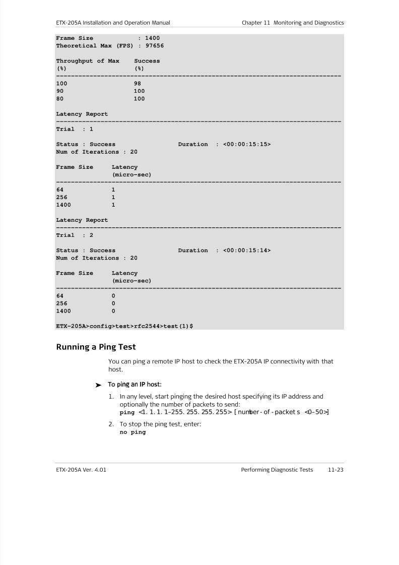
7/25/2019 Manual ETX-205A
http://slidepdf.com/reader/full/manual-etx-205a 327/409
ETX-205A Installation and Operation Manual Chapter 11 Monitoring and Diagnostics
ETX-205A Ver. 4.01 Performing Diagnostic Tests 11-23
Frame Size : 1400
Theoretical Max (FPS) : 97656
Throughput of Max Success
(%) (%)
-----------------------------------------------------------------------------
100 98
90 10080 100
Latency Report
-----------------------------------------------------------------------------
Trial : 1
Status : Success Duration : <00:00:15:15>
Num of Iterations : 20
Frame Size Latency
(micro-sec)
-----------------------------------------------------------------------------
64 1
256 1
1400 1
Latency Report
-----------------------------------------------------------------------------
Trial : 2
Status : Success Duration : <00:00:15:14>
Num of Iterations : 20
Frame Size Latency
(micro-sec)-----------------------------------------------------------------------------
64 0
256 0
1400 0
ETX-205A>config>test>rfc2544>test(1)$
Running a Ping Test
You can ping a remote IP host to check the ETX-205A IP connectivity with that
host.
To ping an IP host:
1. In any level, start pinging the desired host specifying its IP address and
optionally the number of packets to send: ping <1. 1. 1. 1–255. 255. 255. 255> [ number - of - packet s <0–50>]
2. To stop the ping test, enter:no ping

7/25/2019 Manual ETX-205A
http://slidepdf.com/reader/full/manual-etx-205a 328/409
Chapter 11 Monitoring and Diagnostics Installation and Operation Manual
11-24 Performing Diagnostic Tests ETX-205A Ver. 4.01
Tracing the Route
This diagnostic utility traces the route through the network from ETX-205A to the
destination host. The trace route utility supports up to 30 hops.
To trace a route:
• In any level, start the trace route and specify the IP address of the host to
which you intend to trace route:trace-route <1. 1. 1. 1–255. 255. 255. 255>
7/25/2019 Manual ETX-205A
http://slidepdf.com/reader/full/manual-etx-205a 329/409
ETX-205A Installation and Operation Manual Chapter 11 Monitoring and Diagnostics
ETX-205A Ver. 4.01 Technical Support 11-25
11.5 Frequently Asked Questions
Q How should ETX-205A be configured for management?
A
You need to configure a router interface for management by assigning it anIP address, and binding it to an SVI for which management flows have been
configured. Additionally, you need to configure the default gateway address
in the router. Refer to the Quick Start Guide for an example of configuring
ETX-205A for management.
Q If I change the second Ethernet port from network to user, what happens to
the associated flows?
A When you change the functional mode, all flows related to the port are
deleted.
11.6 Technical Support
Technical support for this product can be obtained from the local partner from
whom it was purchased.
RADcare Global Professional Services offers a wide variety of service, support and
training options, including expert consulting and troubleshooting assistance,
online tools, regular training programs, and various equipment coverage options.
For further information, please contact the RAD partner nearest you or one of
RAD's offices worldwide.RAD Data Communications would like your help in improving its product
documentation. Please send us an e-mail with your comments.
Thank you for your assistance!

7/25/2019 Manual ETX-205A
http://slidepdf.com/reader/full/manual-etx-205a 330/409
Chapter 11 Monitoring and Diagnostics Installation and Operation Manual
11-26 Technical Support ETX-205A Ver. 4.01
7/25/2019 Manual ETX-205A
http://slidepdf.com/reader/full/manual-etx-205a 331/409
ETX-205A Ver. 4.01 Prerequisites 12-1
Chapter 12
Software Upgrade
This chapter explains how to upgrade ETX-205A for software version 4.01.
Software upgrade is required to fix product limitations, enable new features, or
to make the unit compatible with other devices that are already running the new
software version.
The device can store up to two software images, referred to as software packs
and named sw-pack-1 through sw-pack-2. You can designate any of the software
packs as active. The non-active software packs serve as backups that can be used
if the active software becomes corrupted.
The CLI allows sw pack 1 through s w pack 4, but only sw pack 1 and sw pack 2 should be used.
The information in this chapter includes the following:
• Detailed conditions required for the upgrade
• Any impact the upgrade may have on the system
• Description of downloading options.
12.1
Software Upgrade OptionsApplication software can be downloaded to ETX-205A via SFTP/TFTP with the
copy command, or via XMODEM, FTP, or TFTP, using the boot menu.
The downloaded software pack can be installed as the active software via the
admin software install command, or by using the boot menu.
12.2 Prerequisites
Before starting the upgrade, verify that you have the following:
• For upgrade via SFTP/FTP/TFTP:
Operational ETX-205A unit with valid IP parameters configured
Connection to a PC with an SFTP/FTP/TFTP server application and a valid IP
address
Software image file stored on the PC. The image file (and exact name)
can be obtained from the local RAD business partner from whom the
device was purchased.
Note
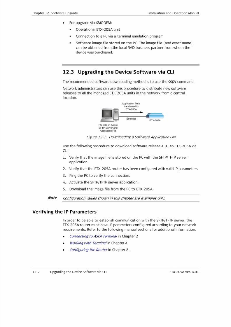
7/25/2019 Manual ETX-205A
http://slidepdf.com/reader/full/manual-etx-205a 332/409
Chapter 12 Software Upgrade Installation and Operation Manual
12-2 Upgrading the Device Software via CLI ETX-205A Ver. 4.01
• For upgrade via XMODEM:
Operational ETX-205A unit
Connection to a PC via a terminal emulation program
Software image file stored on the PC. The image file (and exact name)
can be obtained from the local RAD business partner from whom the
device was purchased.
12.3 Upgrading the Device Software via CLI
The recommended software downloading method is to use the copy command.
Network administrators can use this procedure to distribute new software
releases to all the managed ETX-205A units in the network from a central
location.
Figure 12-1. Downloading a Software Application File
Use the following procedure to download software release 4.01 to ETX-205A via
CLI.
1. Verify that the image file is stored on the PC with the SFTP/TFTP server
application.2. Verify that the ETX-205A router has been configured with valid IP parameters.
3. Ping the PC to verify the connection.
4. Activate the SFTP/TFTP server application.
5. Download the image file from the PC to ETX-205A.
Configuration values shown in this chapter are examples only.
Verifying the IP Parameters
In order to be able to establish communication with the SFTP/TFTP server, the
ETX-205A router must have IP parameters configured according to your network
requirements. Refer to the following manual sections for additional information:
• Connecting to ASCII Terminal in Chapter 2
• Working with Terminal in Chapter 4
• Configuring the Router in Chapter 8.
Note
7/25/2019 Manual ETX-205A
http://slidepdf.com/reader/full/manual-etx-205a 333/409
Installation and Operation Manual Chapter 12 Software Upgrade
ETX-205A Ver. 4.01 Upgrading the Device Software via CLI 12-3
Pinging the PC
Check the integrity of the communication link between ETX-205A and the PC by
pinging the PC from ETX-205A.
To ping the PC:
1. In any level, start pinging the PC specifying its IP address and optionally the
number of packets to send:
ping <i p- addr ess> [ number-of-packets <num- packet s>]
A reply from the PC indicates a proper communication link.
2. If the ping request times out, check the link between ETX-205A and the PC
(physical path, configuration parameters, etc.)
Activating the SFTP Server
Once the SFTP server is activated on the PC, it waits for any SFTP file transfer
request originating from the product, and carries out the received requestautomatically.
SFTP file transfers are carried out through TCP port 22. Make sure that the
firewall you are using on the server allows communication through this port (refer
to Chapter 10 for details).
Activating the TFTP Server
Once the TFTP server is activated on the PC, it waits for any TFTP file transfer
request originating from the product, and carries out the received request
automatically.
TFTP file transfers are carried out through port 69. Make sure that the firewallyou are using on the server allows communication through this port (refer to
Chapter 10 for details).
Configure the connection timeout of the TFTP server to be more than 30 seconds
to prevent an automatic disconnection during the backup partition deletion
(about 25 seconds).
Downloading the Software
This procedure is used to download the new software release.
To copy the image file to the ETX-205A unit:
• In any level, enter:
copy
sftp://<user name>:<passwor d>@<i p- address>/<i mage- f i l e- name>
<sw- pack- n>
Where <i p- address> is the IP address of the PC where the SFTP server is
installed, and <n> is the index of the desired software pack.
Note
7/25/2019 Manual ETX-205A
http://slidepdf.com/reader/full/manual-etx-205a 334/409
Chapter 12 Software Upgrade Installation and Operation Manual
12-4 Upgrading the Device Software via CLI ETX-205A Ver. 4.01
Or
copy tftp://<t f t p- i p- addr ess>/<i mage- f i l e- name> <sw- pack- n>
Where tftp-ip-address is the IP address of the PC where the TFTP server
is installed, and <n> is the index of the desired software pack.
Choose an index that is not being used by the active software, or by a software
pack that you do not want to overwrite.
The software download is performed. See Installing Software for
instructions on installing the downloaded software as the active
software.
Installing Software
After software is downloaded to ETX-205A, it has to be installed via the install
command as the active software. When you install software, by default ETX-205A
creates a restore point, so that if there is a problem with the new software pack,
you can perform a rollback to the previous software pack.
The file startup config must exist before you can install software with creation of
a restore point.
You can request (via command software-confirm-required) that the next installed
software be confirmed after the next reboot. When you execute the request,
then the next time ETX-205A reboots and loads the new software, you must
confirm the software (via command software-confirm) within the configured
timeout period. If the confirmation is not received before timeout, ETX-205A
automatically falls back to its previous software.
To request software confirmation:
• At the admin>software prompt, enter:software-confirm-required [ time-to-confirm <mi nut es>]
The confirmation timeout can be from five minutes to 24 hours. If you do not
specify it, the default is five minutes.
You can cancel the software confirmation request by enteringno software-confirm-required .
Next time ETX-205A reboots and loads new software, it starts a
confirmation timer. See the following procedure for more details on the
confirmation.
To install a software pack as active:
If startup config does not exist, you must install the software pack without
creating a restore point.
1. At the admin>software prompt, enter:install <f i l ename> [ no-restore-point]
The parameter <filename> can be any of the non-active software packs
(sw-pack-1 through sw-pack-2). If you specify no-restore-point, then after
Note
Note
Note
Note
7/25/2019 Manual ETX-205A
http://slidepdf.com/reader/full/manual-etx-205a 335/409
Installation and Operation Manual Chapter 12 Software Upgrade
ETX-205A Ver. 4.01 Upgrading the Device Software via the Boot Menu 12-5
the software is installed, it is not possible to rollback to the previous
software.
You are prompted to confirm the operation.
!Device will install file and reboot. Are you sure? [yes/no] _
2. Type yes to confirm.
If a restore point is being created, then startup-config is copied to
restore-point-config. ETX-205A designates the specified software pack as
active, then reboots.
3. If a software confirmation request is active, ETX-205A starts a timer with the
specified timeout period.
While the confirmation timer is running, ETX-205A does not allow any commands
that change its configuration.
4. If the software-confirm command is entered before the timer expires, the
software is considered to be confirmed.
5. If the software-confirm command is not entered before the timer expires,
then restore-point-config is deleted, ETX-205A designates the previously
active software pack as active, then reboots.
Restoring Previous Active Software
If the installed software malfunctions and was installed with a restore point, you
can perform rollback to the previous active software.
To rollback to the previous active software pack:
1.
At the admin>software# prompt, enter:undo-install
You are prompted to confirm the operation.
! Falling back to restore point ! Are you sure? [yes/no] _
2. Type yes to confirm.
The file restore-point-config is renamed to startup-config. ETX-205A
designates the previously active software pack as active, then reboots.
12.4
Upgrading the Device Software via the BootMenu
Software downloading can also be performed using the Boot menu. The Boot
menu can be reached while ETX-205A performs initialization, for example, after
power-up.
You may need to start the loading from the Boot menu if you are unable to use
the copy command (for example, because the ETX-205A software has not yet
been downloaded or is corrupted).
Note
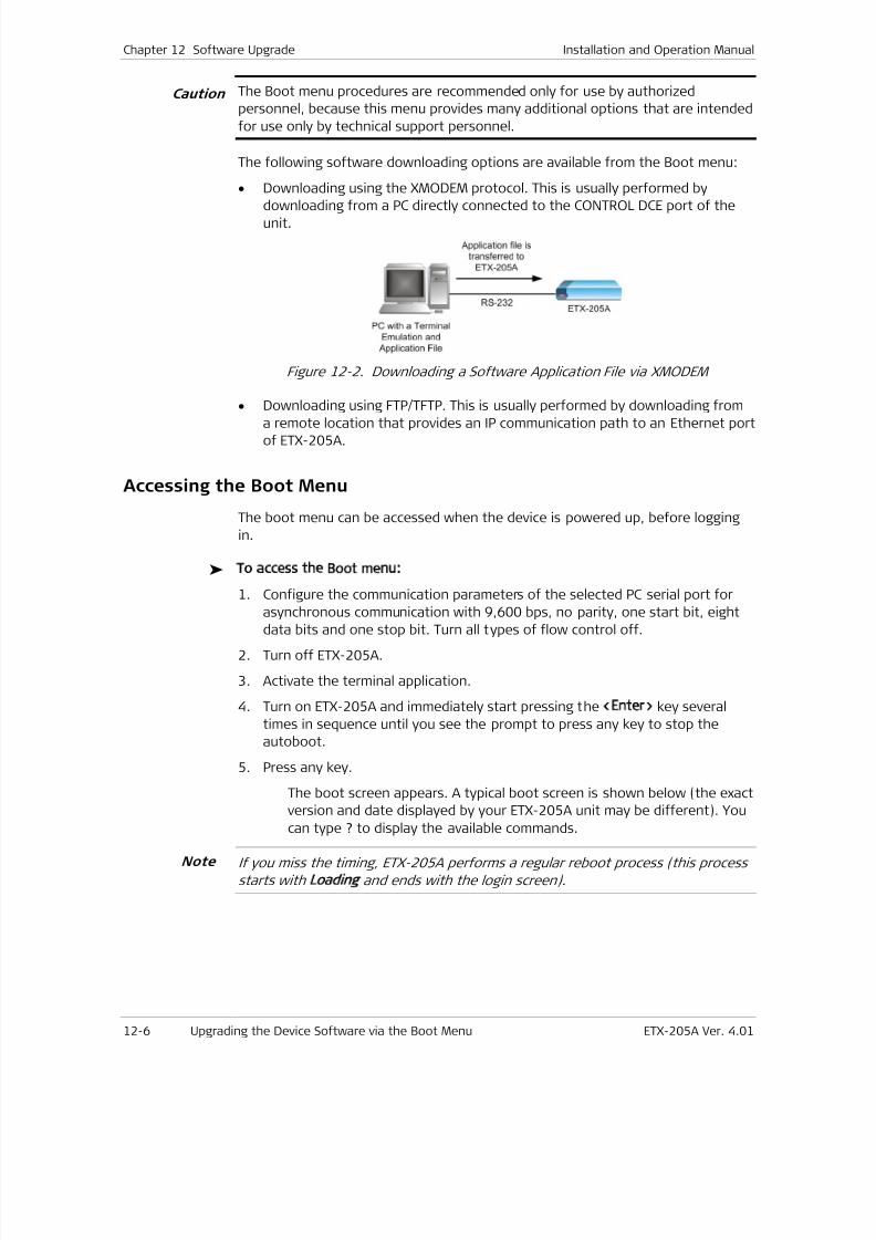
7/25/2019 Manual ETX-205A
http://slidepdf.com/reader/full/manual-etx-205a 336/409
Chapter 12 Software Upgrade Installation and Operation Manual
12-6 Upgrading the Device Software via the Boot Menu ETX-205A Ver. 4.01
The Boot menu procedures are recommended only for use by authorized
personnel, because this menu provides many additional options that are intended
for use only by technical support personnel.
The following software downloading options are available from the Boot menu:
• Downloading using the XMODEM protocol. This is usually performed by
downloading from a PC directly connected to the CONTROL DCE port of theunit.
Figure 12-2. Downloading a Software Application File via XMODEM
•
Downloading using FTP/TFTP. This is usually performed by downloading froma remote location that provides an IP communication path to an Ethernet port
of ETX-205A.
Accessing the Boot Menu
The boot menu can be accessed when the device is powered up, before logging
in.
To access the Boot menu:
1. Configure the communication parameters of the selected PC serial port for
asynchronous communication with 9,600 bps, no parity, one start bit, eightdata bits and one stop bit. Turn all types of flow control off.
2. Turn off ETX-205A.
3. Activate the terminal application.
4. Turn on ETX-205A and immediately start pressing the <Enter> key several
times in sequence until you see the prompt to press any key to stop the
autoboot.
5. Press any key.
The boot screen appears. A typical boot screen is shown below (the exact
version and date displayed by your ETX-205A unit may be different). You
can type ? to display the available commands.
If you miss the timing, ETX-205A performs a regular reboot process (this process
starts with Loading and ends with the login screen).
Caution
Note
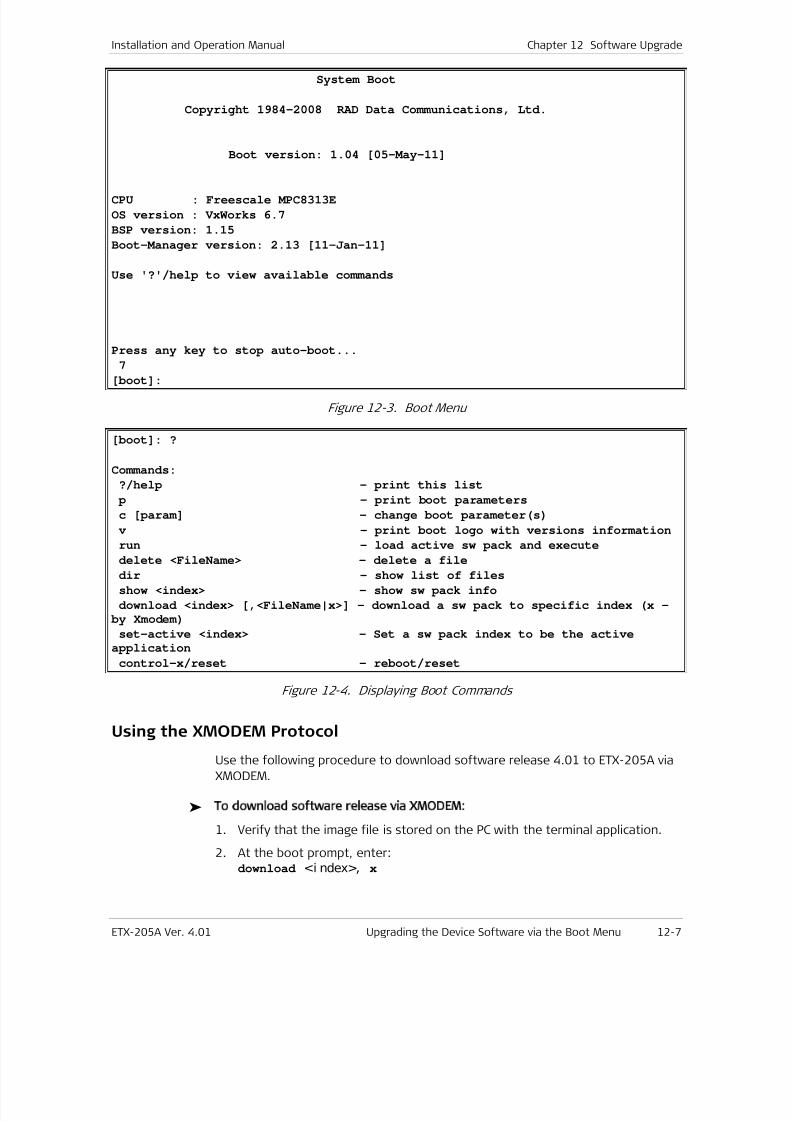
7/25/2019 Manual ETX-205A
http://slidepdf.com/reader/full/manual-etx-205a 337/409
Installation and Operation Manual Chapter 12 Software Upgrade
ETX-205A Ver. 4.01 Upgrading the Device Software via the Boot Menu 12-7
System Boot
Copyright 1984-2008 RAD Data Communications, Ltd.
Boot version: 1.04 [05-May-11]
CPU : Freescale MPC8313E
OS version : VxWorks 6.7
BSP version: 1.15
Boot-Manager version: 2.13 [11-Jan-11]
Use '?'/help to view available commands
Press any key to stop auto-boot...
7
[boot]:
Figure 12-3. Boot Menu
[boot]: ?
Commands:
?/help - print this list
p - print boot parameters
c [param] - change boot parameter(s)
v - print boot logo with versions information
run - load active sw pack and execute
delete <FileName> - delete a filedir - show list of files
show <index> - show sw pack info
download <index> [,<FileName|x>] - download a sw pack to specific index (x -
by Xmodem)
set-active <index> - Set a sw pack index to be the active
application
control-x/reset - reboot/reset
Figure 12-4. Displaying Boot Commands
Using the XMODEM Protocol
Use the following procedure to download software release 4.01 to ETX-205A via
XMODEM.
To download software release via XMODEM:
1. Verify that the image file is stored on the PC with the terminal application.
2. At the boot prompt, enter:download <i ndex>, x
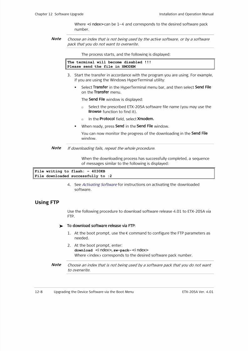
7/25/2019 Manual ETX-205A
http://slidepdf.com/reader/full/manual-etx-205a 338/409
Chapter 12 Software Upgrade Installation and Operation Manual
12-8 Upgrading the Device Software via the Boot Menu ETX-205A Ver. 4.01
Where <i ndex> can be 1–4 and corresponds to the desired software pack
number.
Choose an index that is not being used by the active software, or by a software
pack that you do not want to overwrite.
The process starts, and the following is displayed:
The terminal will become disabled !!!
Please send the file in XMODEM
3. Start the transfer in accordance with the program you are using. For example,
if you are using the Windows HyperTerminal utility:
Select Transfer in the HyperTerminal menu bar, and then select Send File
on the Transfer menu.
The Send File window is displayed:
Select the prescribed ETX-205A software file name (you may use the
Browse function to find it).
In the Protocol field, select Xmodem.
When ready, press Send in the Send File window.
You can now monitor the progress of the downloading in the Send File
window.
If downloading fails, repeat the whole procedure.
When the downloading process has successfully completed, a sequence
of messages similar to the following is displayed:
File writing to flash: - 4030KB
File downloaded successfully to :2
4. See Activating Software for instructions on activating the downloaded
software.
Using FTP
Use the following procedure to download software release 4.01 to ETX-205A via
FTP.
To download software release via FTP:
1.
At the boot prompt, use the c command to configure the FTP parameters asneeded.
2. At the boot prompt, enter:download <i ndex>,sw-pack-<i ndex>
Where <index> corresponds to the desired software pack number.
Choose an index that is not being used by a software pack that you do not want
to overwrite.
Note
Note
Note
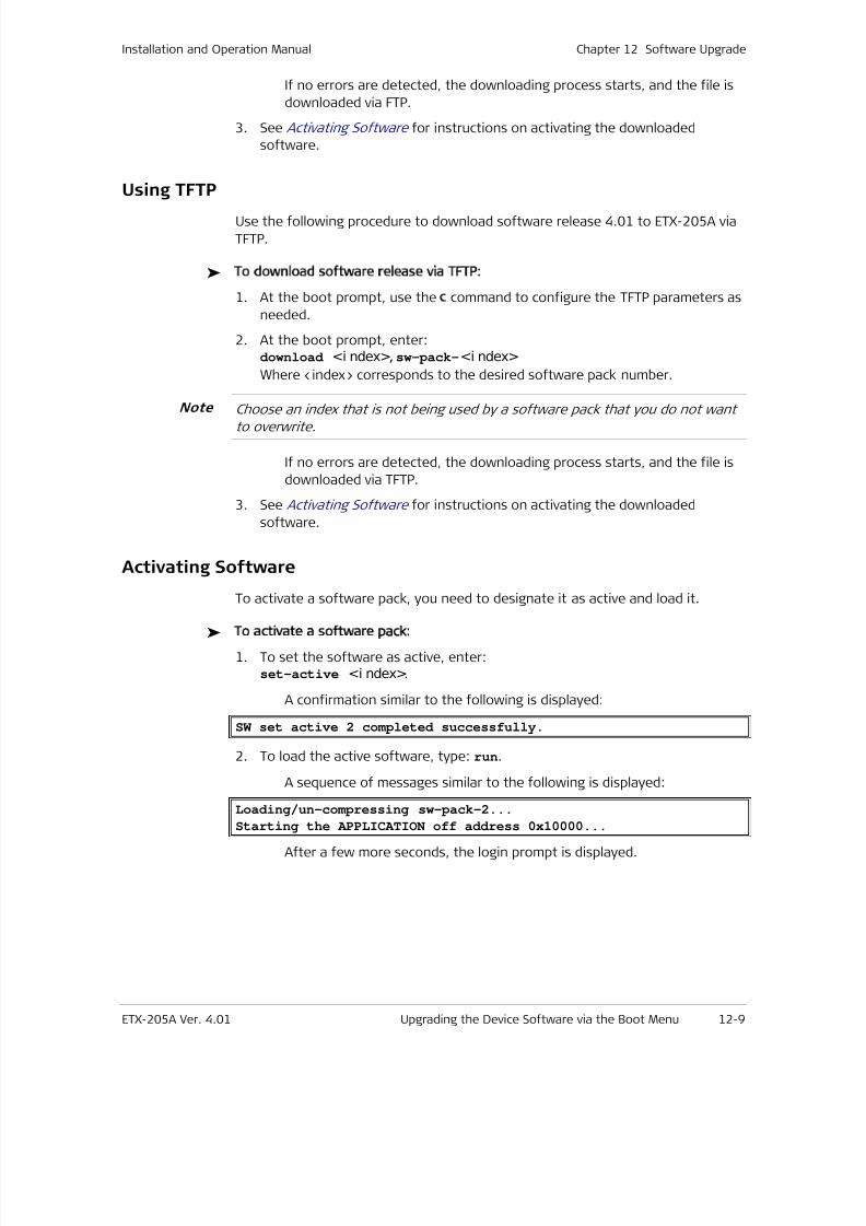
7/25/2019 Manual ETX-205A
http://slidepdf.com/reader/full/manual-etx-205a 339/409
Installation and Operation Manual Chapter 12 Software Upgrade
ETX-205A Ver. 4.01 Upgrading the Device Software via the Boot Menu 12-9
If no errors are detected, the downloading process starts, and the file is
downloaded via FTP.
3. See Acti vating Software for instructions on activating the downloaded
software.
Using TFTP
Use the following procedure to download software release 4.01 to ETX-205A via
TFTP.
To download software release via TFTP:
1. At the boot prompt, use the c command to configure the TFTP parameters as
needed.
2. At the boot prompt, enter:download <i ndex>,sw-pack-<i ndex>
Where <index> corresponds to the desired software pack number.
Choose an index that is not being used by a software pack that you do not wantto overwrite.
If no errors are detected, the downloading process starts, and the file is
downloaded via TFTP.
3. See Activating Software for instructions on activating the downloaded
software.
Activating Software
To activate a software pack, you need to designate it as active and load it.
To activate a software pack:
1. To set the software as active, enter:set-active <i ndex>.
A confirmation similar to the following is displayed:
SW set active 2 completed successfully.
2. To load the active software, type: run.
A sequence of messages similar to the following is displayed:
Loading/un-compressing sw-pack-2...Starting the APPLICATION off address 0x10000...
After a few more seconds, the login prompt is displayed.
Note

7/25/2019 Manual ETX-205A
http://slidepdf.com/reader/full/manual-etx-205a 340/409
Chapter 12 Software Upgrade Installation and Operation Manual
12-10 Verifying Upgrade Results ETX-205A Ver. 4.01
12.5 Verifying Upgrade Results
To verify that the upgrade was successful, log on to ETX-205A via a terminal
emulation program to view the Inventory table (show inventory-table at prompt
config>system ), and verify the active software version in the SW Rev column.
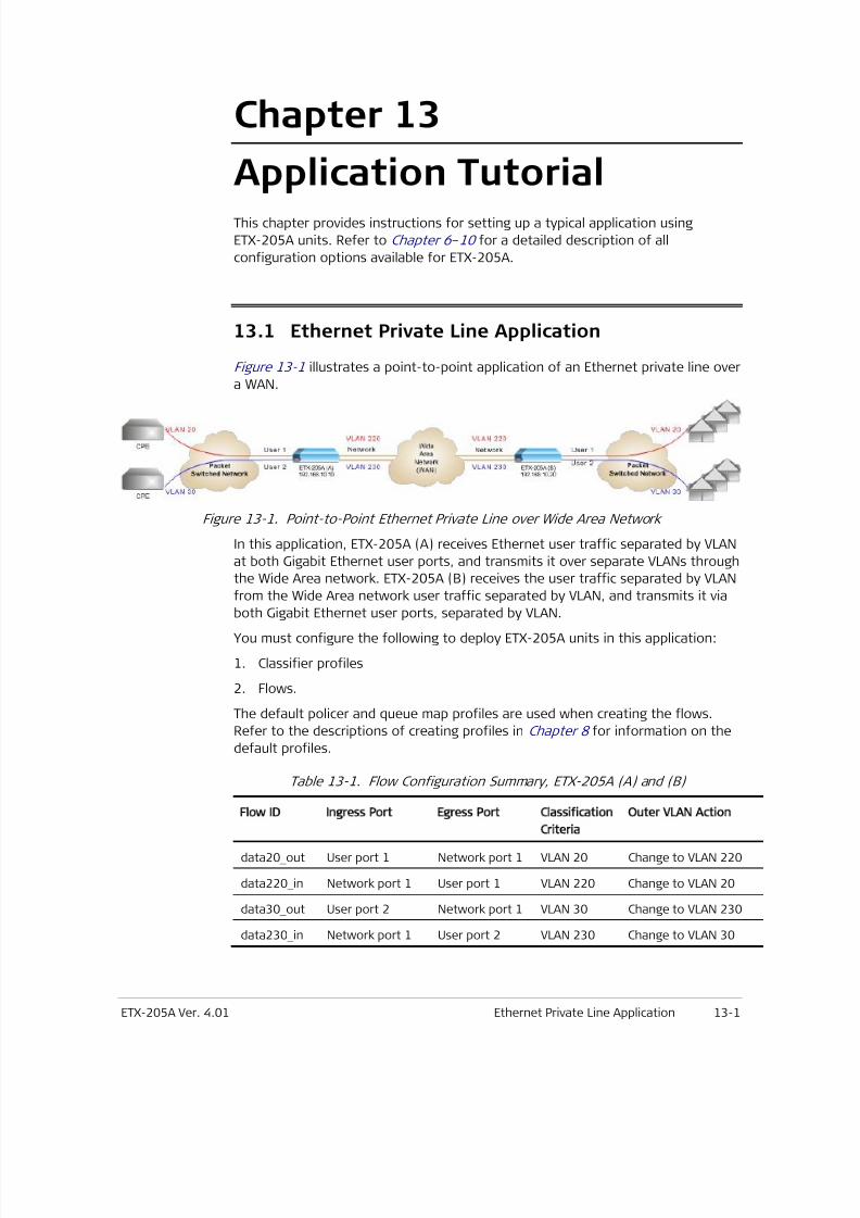
7/25/2019 Manual ETX-205A
http://slidepdf.com/reader/full/manual-etx-205a 341/409
ETX-205A Ver. 4.01 Ethernet Private Line Application 13-1
Chapter 13
Application TutorialThis chapter provides instructions for setting up a typical application using
ETX-205A units. Refer to Chapter 6–10 for a detailed description of all
configuration options available for ETX-205A.
13.1
Ethernet Private Line Application
Figure 13-1 illustrates a point-to-point application of an Ethernet private line over
a WAN.
Figure 13-1. Point-to-Point Ethernet Private Line over Wide Area Network
In this application, ETX-205A (A) receives Ethernet user traffic separated by VLAN
at both Gigabit Ethernet user ports, and transmits it over separate VLANs through
the Wide Area network. ETX-205A (B) receives the user traffic separated by VLAN
from the Wide Area network user traffic separated by VLAN, and transmits it via
both Gigabit Ethernet user ports, separated by VLAN.
You must configure the following to deploy ETX-205A units in this application:
1. Classifier profiles
2. Flows.
The default policer and queue map profiles are used when creating the flows.
Refer to the descriptions of creating profiles in Chapter 8 for information on the
default profiles.
Table 13-1. Flow Configuration Summary, ETX-205A (A) and (B)
Flow ID Ingress Port Egress Port Classification
Criteria
Outer VLAN Action
data20 _ out User port 1 Network port 1 VLAN 20 Change to VLAN 220
data220 _ in Network port 1 User port 1 VLAN 220 Change to VLAN 20
data30 _ out User port 2 Network port 1 VLAN 30 Change to VLAN 230
data230 _ in Network port 1 User port 2 VLAN 230 Change to VLAN 30
7/25/2019 Manual ETX-205A
http://slidepdf.com/reader/full/manual-etx-205a 342/409
Chapter 13 Application Tutorial Installation and Operation Manual
13-2 Ethernet Private Line Application ETX-205A Ver. 4.01
Configuring Classifier Profiles
In both units, you have to create classifier profiles for VLANs 20, 30, 220, and
230. The same scripts can be used in both units, therefore they are presented
here only once.
To create the classifier profile for VLAN 2 :
•
Execute the following script to create the classifier profile for VLAN 20.
configure flows
classifier-profile vlan20 match-any
match vlan 20
exit all
To create the classifier profile for VLAN 3 :
• Execute the following script to create the classifier profile for VLAN 30.
configure flows
classifier-profile vlan30 match-any
match vlan 30
exit all
To create the classifier profile for VLAN 22 :
• Execute the following script to create the classifier profile for VLAN 220.
configure flows
classifier-profile vlan220 match-any
match vlan 220
exit all
To create the classifier profile for VLAN 23 :
• Execute the following script to create the classifier profile for VLAN 230.
configure flows
classifier-profile vlan230 match-any
match vlan 230
exit all
Configuring Flows
In both units, you have to create four flows, as flows are unidirectional (see
Table 13-1).
• Flow data20 _ out from user port 1 (ethernet 3) to network port 1 (ethernet
1), changing VLAN 20 to VLAN 220
• Flow data220 _ in from network port 1 (ethernet 1) to user port 1 (ethernet
3), changing VLAN 220 to VLAN 20
• Flow data30 _ out from user port 2 (ethernet 4) to network port 1 (ethernet
1), changing VLAN 30 to VLAN 230
• Flow data230 _ in from network port 1 (ethernet 1) to user port 2 (ethernet
4), changing VLAN 230 to VLAN 30
7/25/2019 Manual ETX-205A
http://slidepdf.com/reader/full/manual-etx-205a 343/409
Installation and Operation Manual Chapter 13 Application Tutorial
ETX-205A Ver. 4.01 Ethernet Private Line Application 13-3
The same scripts can be used in both units, therefore they are presented here
only once.
To create flow data2 out:
• Execute the following script to create flow data20 _ out as shown in
Table 13-1.
configure flows flow data20_out
classifier vlan20
policer profile Policer1
ingress-port ethernet 3
egress-port ethernet 1 queue-map CosProfile1 block 0/1
mark all
vlan 220
no shutdown
exit all
To create flow data22 in:
• Execute the following script to create flow data220 _ in as shown in
Table 13-1. configure flows flow data220_in
classifier vlan220
policer profile Policer1
ingress-port ethernet 1
egress-port ethernet 3 queue-map CosProfile1 block 0/1
mark all
vlan 20
no shutdown
exit all
To create flow data3 out:
•
Execute the following script to create flow data30 _ out as shown in
Table 13-1.
configure flows flow data30_out
classifier vlan30
policer profile Policer1
ingress-port ethernet 4
egress-port ethernet 1 queue-map CosProfile1 block 0/1
mark all
vlan 230
no shutdown
exit all

7/25/2019 Manual ETX-205A
http://slidepdf.com/reader/full/manual-etx-205a 344/409
Chapter 13 Application Tutorial Installation and Operation Manual
13-4 Ethernet Private Line Application ETX-205A Ver. 4.01
To create flow data23 in:
• Execute the following script to create flow data230 _ in as shown in
Table 13-1.
configure flows flow data230_in
classifier vlan230
policer profile Policer1
ingress-port ethernet 1egress-port ethernet 4 queue-map CosProfile1 block 0/1
mark all
vlan 30
no shutdown
exit all
7/25/2019 Manual ETX-205A
http://slidepdf.com/reader/full/manual-etx-205a 345/409
ETX-205A Ver. 4.01 MNG Connector A-1
Appendix A
Connection Data
A.1
Ethernet Connector
The Ethernet electrical interface portion of the SFP/UTP combo ports terminates
in 8-pin RJ-45 connectors, of type 10/100/1000BaseT, wired in accordance with
Table A-1. The connector supports both MDI and MDIX modes.
Table A-1. 10/100/1000BaseT Connector Pinout
Pin M I M IX
1 A+ B+
2 A- B-
3 B+ A+
4 C+ D+
5 C- D-
6 B- A-
7 D+ C+
8 D- C-
A.2
MNG Connector
The ETX-205A Ethernet management port uses an electrical interface that
terminates in an RJ-45, 8-pin connector. The port supports MDI and MDIX modes.
Table A-2 lists the pin assignments.
Table A-2. MNG Pinout
Pin esignation Function
1 RxD+ Receive Data output, + wire
2 RxD– Receive Data output, – wire
3 TxD+ Transmit Data input, + wire
4,5 – Not connected
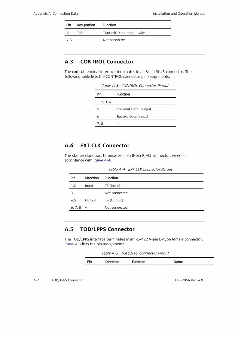
7/25/2019 Manual ETX-205A
http://slidepdf.com/reader/full/manual-etx-205a 346/409
Appendix A Connection Data Installation and Operation Manual
A-2 TOD/1PPS Connector ETX-205A Ver. 4.01
Pin esignation Function
6 TxD- Transmit Data input, – wire
7,8 – Not connected
A.3
CONTROL Connector
The control terminal interface terminates in an 8-pin RJ-45 connector. The
following table lists the CONTROL connector pin assignments.
Table A-3. CONTROL Connector Pinout
Pin Function
1, 2, 3, 4 –
5 Transmit Data (output)
6 Receive Data (input)
7, 8 –
A.4
EXT CLK Connector
The station clock port terminates in an 8-pin RJ-45 connector, wired in
accordance with Table A-4 .
Table A-4. EXT CLK Connector Pinout
Pin irection Function
1,2 Input T3 (Input)
3 – Not connected
4,5 Output T4 (Output)
6, 7, 8 – Not connected
A.5
TOD/1PPS Connector
The TOD/1PPS interface terminates in an RS-422 9-pin D-type female connector.
Table A-5 lists the pin assignments.
Table A-5. TOD/1PPS Connector Pinout
Pin irection Function Name

7/25/2019 Manual ETX-205A
http://slidepdf.com/reader/full/manual-etx-205a 347/409
Installation and Operation Manual Appendix A Connection Data
ETX-205A Ver. 4.01 TOD/1PPS Connector A-3
1 In/Out Receive/Transmit Data RS422_1PPS +
2 In/Out Receive/Transmit Data RS422_1PPS -
3 – Not connected –
4 In Receive Data RS422_RX +
5 In Receive Data RS422_RX -
6 – Ground GND
7 Out Transmit Data RS422_TX_TOD-
8 Out Transmit Data RS422_TX_TOD+
9 – Not connected –

7/25/2019 Manual ETX-205A
http://slidepdf.com/reader/full/manual-etx-205a 348/409
Appendix A Connection Data Installation and Operation Manual
A-4 TOD/1PPS Connector ETX-205A Ver. 4.01
7/25/2019 Manual ETX-205A
http://slidepdf.com/reader/full/manual-etx-205a 349/409
ETX-205A Ver. 4.01 Introduction B-1
Appendix B
Operation,
Administration, and
Maintenance (OAM)
B.1
Introduction
ETX-205A supports standard implementation of Ethernet OAM based on
ITU-T Y.1731 and IEEE 802.1ag-D8. Pre-standard implementation based on
Y.1731 is supported for backward compatibility, for instance when working
opposite a device with an older version of Ethernet OAM software. This appendix
describes the pre-standard implementation. The standard implementation can be
found in the ITU-T Y.1731 and IEEE 802.1ag-D8 documentation.
The pre-standard OAM implementation provides the following:
• Continuity check
• Non-intrusive loopback which used to detect loss of bidirectional continuity
• Performance measurements (per service).
Table B-1 lists the Ethernet OAM-related terms used in the appendix.
Table B-1. Ethernet OAM Terminology
Term Description
UNI User Network Interface. The physical demarcation point
between the responsibility of the Service Provider and the
responsibility of the Subscriber
UNI_C Customer side of a UNI link
UNI_N Network side of a UNI link
Service frame An Ethernet frame transmitted across the UNI toward the
Service Provider or an Ethernet frame transmitted across the
UNI toward the Subscriber.
Flow Ethernet Virtual Connection : An association of two or more
UNIs that limits the exchange of Service Frames to UNIs in the
Ethernet Virtual Connection
Point-to-point Flow Flow connecting exactly two UNIs
7/25/2019 Manual ETX-205A
http://slidepdf.com/reader/full/manual-etx-205a 350/409
Appendix B Operation, Administration, and Maintenance (OAM) Installation and Operation Manual
B-2 Reference Architecture ETX-205A Ver. 4.01
Term Description
Multipoint-to-Multipoint
Flow
Flow connecting two or more UNIs
Service Instance / Class
of service (CoS)
A set of Service Frames that have a commitment from the
Service Provider to receive a particular level of performance
Service InstanceIdentifier (CoS ID)
Service Frame delivery performance is specified for all ServiceFrames transported within a flow with a particular Class of
Service instance. The Class of Service instance is identified by a
Class of Service Identifier associated with each Service Frame
(Class of service can be identified by more than one
parameter/frame attribute)
MEP Proactive OAM reference point which is capable to initiate and
terminate proactive OAM frames. MEP is also capable to initiate
and react to diagnostics OAM frames.
MIP A provisioned OAM reference point which is capable to respond
to diagnostics OAM frames initiated by the MEP.
MEP Service Instance
Source
The receiver of OAM frames in each Service Instance
MEP Service Instance
Destination
The transmitter of OAM frames in each Service Instance
B.2
Reference Architecture
Figure B-1 illustrates two OAM flows:
• OAM flow originating from the CPE
The CPE-to-CPE OAM flow is transferred transparently by ETX-205A and
treated as data.
• OAM flow originating from the ETX-205A devices.
The ETX-205A OAM flow runs on a data flow on the same VLAN.
The ETX-205A units terminate the OAM flow and can be referred as a
Maintenance Entity (ME). Each device supports up to 8 such MEs. In this case,
the ETX-205A units act as MEPs (Maintenance End-Points) and not as a MIP
(Maintenance Intermediate Points) and all measurements are performed on
the UNI_N to UNI_N segment.
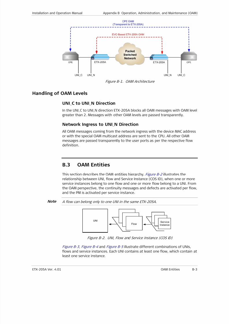
7/25/2019 Manual ETX-205A
http://slidepdf.com/reader/full/manual-etx-205a 351/409
Installation and Operation Manual Appendix B Operation, Administration, and Maintenance (OAM)
ETX-205A Ver. 4.01 OAM Entities B-3
Figure B-1. OAM Architecture
Handling of OAM Levels
UNI_C to UNI_N Direction
In the UNI_C to UNI_N direction ETX-205A blocks all OAM messages with OAM level
greater than 2. Messages with other OAM levels are passed transparently.
Network Ingress to UNI_N Direction
All OAM messages coming from the network ingress with the device MAC address
or with the special OAM multicast address are sent to the CPU. All other OAM
messages are passed transparently to the user ports as per the respective flow
definition.
B.3
OAM Entities
This section describes the OAM entities hierarchy. Figure B-2 illustrates the
relationship between UNI, flow and Service Instance (COS ID), when one or more
service instances belong to one flow and one or more flow belong to a UNI. From
the OAM perspective, the continuity messages and defects are activated per flow,
and the PM is activated per service instance.
A flow can belong only to one UNI in the same ETX-205A.
UNI
FlowServiceInstance
Figure B-2. UNI, Flow and Service Instance (COS ID)
Figure B-3 , Figure B-4 and Figure B-5 illustrate different combinations of UNIs,
flows and service instances. Each UNI contains at least one flow, which contain at
least one service instance.
Note
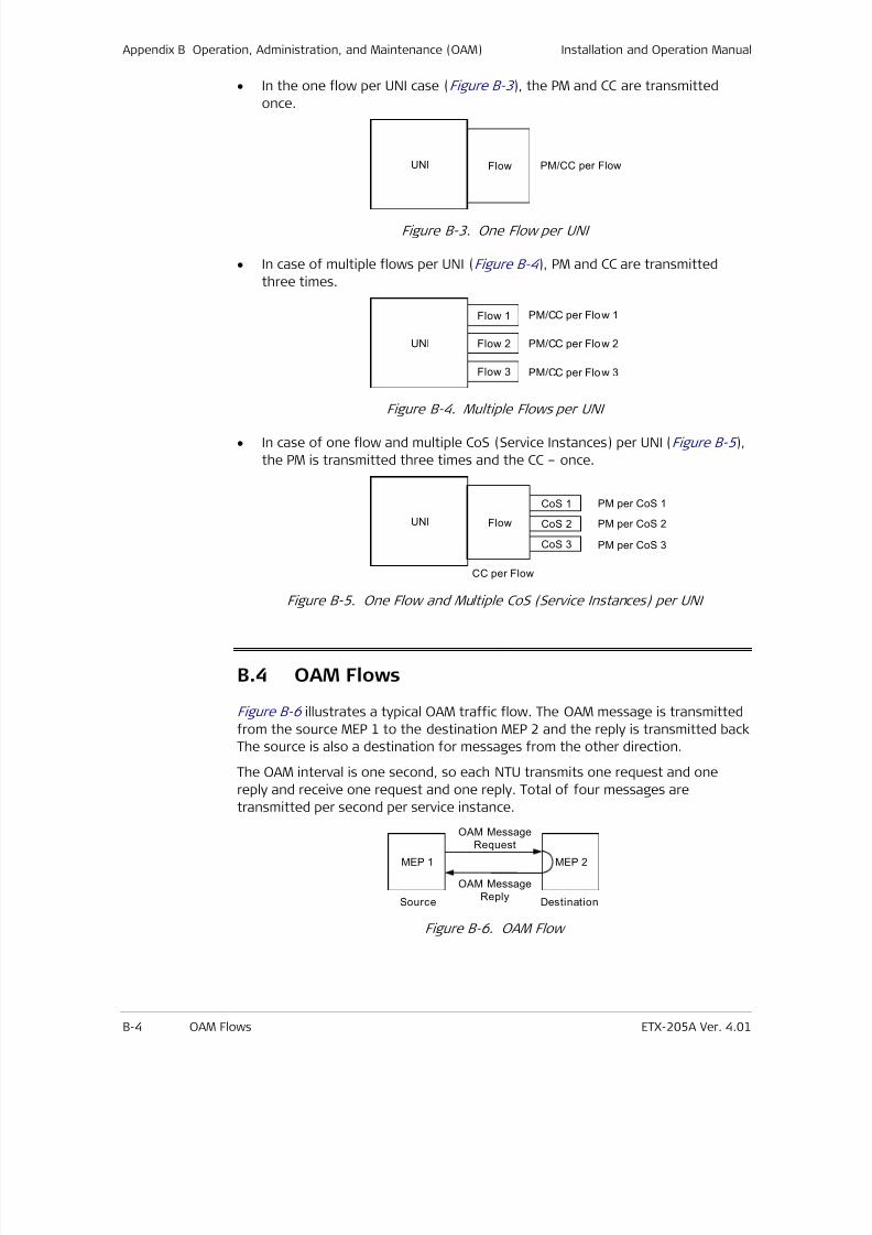
7/25/2019 Manual ETX-205A
http://slidepdf.com/reader/full/manual-etx-205a 352/409
Appendix B Operation, Administration, and Maintenance (OAM) Installation and Operation Manual
B-4 OAM Flows ETX-205A Ver. 4.01
• In the one flow per UNI case (Figure B-3 ), the PM and CC are transmitted
once.
UNI Flow PM/CC per Flow
Figure B-3. One Flow per UNI
• In case of multiple flows per UNI (Figure B-4 ), PM and CC are transmitted
three times.
UNI
PM/CC per Flow 1
Flow 2
Flow 1
Flow 3
PM/CC per Flow 2
PM/CC per Flow 3
Figure B-4. Multiple Flows per UNI
• In case of one flow and multiple CoS (Service Instances) per UNI (Figure B-5 ),
the PM is transmitted three times and the CC – once.
UNI Flow
CC per Flow
CoS 1
CoS 2
CoS 3
PM per CoS 1
PM per CoS 2
PM per CoS 3
Figure B-5. One Flow and Multiple CoS (Service Instances) per UNI
B.4
OAM Flows
Figure B-6 illustrates a typical OAM traffic flow. The OAM message is transmitted
from the source MEP 1 to the destination MEP 2 and the reply is transmitted back
The source is also a destination for messages from the other direction.
The OAM interval is one second, so each NTU transmits one request and one
reply and receive one request and one reply. Total of four messages are
transmitted per second per service instance.
MEP 1 MEP 2
Source Destination
OAM Message
Request
OAM Message
Reply
Figure B-6. OAM Flow
7/25/2019 Manual ETX-205A
http://slidepdf.com/reader/full/manual-etx-205a 353/409
Installation and Operation Manual Appendix B Operation, Administration, and Maintenance (OAM)
ETX-205A Ver. 4.01 OAM Flows B-5
OAM Message Addressing
The OAM defines two modes of addressing, unicast and multicast. Unicast
addressing is used for point-to-point connections, while multicast addressing is
used in cases where the MAC address of the destination MEP is not known.
Currently ETX-205A supports point-to-point flows in proprietary mode.
OAM Message Association
On the receiver side the OAM frame is associated with a flow and a service.
Flow Association
When an OAM frame is associated with a flow, the following steps are performed:
• Request message reception
When a request message is received, the VLAN is extracted to find the Flow
ID. The Flow ID found at the receiver is compared against the Flow ID in the
frame. If the IDs are equal, further service association is made. If it is not
found, the “Flow ID no match” notification is returned in the reply message.
• Reply message reception
When a reply message is received, the VLAN is extracted to find the Flow ID.
The Flow ID found at the receiver is compared against the Flow ID in the
frame. If the IDs are equal, further service association is made. If it is not
found, the frame is discarded and connectivity alarm is issued.
Service Association
When an OAM frame is associated with a service, the following steps are
performed:
• Request message reception
The class of service characteristics are extracted from the frame and must be
matched to an entry in the flows <-> services table at the receiver. If they are
matched, the frame is processed. If not, the service ID is returned with the
“Not Found” notification.
• Reply message reception
The class of service characteristics are extracted from the frame and must be
matched to an entry in the flow <-> services table at the receiver. If they are
matched, the frame is processed. If not, the frame is discarded.
Ethernet Loopback (ETH-LB)
The ETH-LB can be used to verify connectivity. The ETH-LB is performed by
sending a request ETH-LB message to the remote unit and expecting an ETH-LB
reply message back to verify connectivity. When the insertion rate of ETH-LB
messages is much slower compared to data rate between the flow points.
Unicast ETH-LB request message is sent from a MEP to a specific MEP (remote
device). The DA of the request message is a unicast MAC address of destination
device. Upon receipt of the request message, the MEP responds with unicast ETH-
7/25/2019 Manual ETX-205A
http://slidepdf.com/reader/full/manual-etx-205a 354/409
Appendix B Operation, Administration, and Maintenance (OAM) Installation and Operation Manual
B-6 OAM Flows ETX-205A Ver. 4.01
LB reply message. The DA of the reply message is a unicast MAC address of
requesting device, learned from request message.
Continuity Check (ETH-CC)
Ethernet Continuity Check (ETH-CC) can be used to detect continuity failures
across flows between a given pair of edge service point on a flow. Continuity
failures are caused by:
• Major failures (link failure, device failure, network path failure etc)
• Minor failures (software failure, memory corruption, incorrect configuration
etc).
The ETH-CC signal is generated by one MEP. Upon receipt of the first ETH-CC
signal from a sending MEP, the receiving MEP detects continuity with sending MEP
and expects to receive further periodic ETH-CC signals. Once the receiving MEP
stops receiving periodic ETH-CC signals from sending MEP, it declares continuity
failure.
OAM Procedures
This section discusses the continuity check (CC) and the performance
measurement (PM) procedures.
Continuity Check Procedure
The loopback message and the ETH-CC messages are used for continuity check. In
case the services are defined and PM collection is enabled, they are also used to
carry PM messages. If PM collection is disabled, the messages are used for
continuity check only.
If the RX CC mode of the receiver is configured to CC-based, the continuitydetection is based on ETH-CC. If the mode is set to LB-based, the continuity
detection is based on ETH-LB. If the mode is disabled, the continuity detection is
not performed.
ETH-LB Method
The ETH-LB method includes the following elements:
• Unicast ETH-LB transmission
Unicast ETH-LB request message is transmitted by a MEP (ETX-205A) every
1 second. The transmitted Transaction Identifier is retained for at least
5 seconds after the unicast ETH-LB signal is transmitted. The Transaction
Identifier must be changed for every unicast ETH-LB message, and no
Transaction Identifier from the same MEP is allowed to be repeated within
1 minute.
• Unicast ETH-LB reception and reply transmission
Whenever a valid unicast ETH-LB request message is received by MEP
(ETX-205A), a unicast ETH-LB reply message is generated and transmitted to
the requesting MEP. Every field in the unicast ETH-LB request message is
copied to the unicast ETH-LB reply message with the following exceptions:
7/25/2019 Manual ETX-205A
http://slidepdf.com/reader/full/manual-etx-205a 355/409
Installation and Operation Manual Appendix B Operation, Administration, and Maintenance (OAM)
ETX-205A Ver. 4.01 OAM Flows B-7
The source and destination MAC addresses are swapped.
The OpCode field is vendor-specific 0xFE.
The Flow and MEP ID are processed as follows: if the Flow/MEP ID do not
exist in the device, it changes them to “No Match” otherwise they are left
intact.
• Unicast ETH-LB reply receipt
When a unicast ETH-LB reply message is received by a MEP (ETX-205A)
diagnostic flow termination function, it examines the TLVs returned in the
unicast ETH-LB reply message. The signal is declared invalid if the TLVs do not
match those sent in the corresponding unicast ETH-LB request signal,
including MEP ID and Flow ID.
• Continuity declarations
Loss of Continuity and Connectivity Mismatch states are declared by the
ETH-LB mechanism.
Loss of continuity declaration
After the source device sends an ETH-LB message a timer is set with a3.52 second timeout. If the destination device does send reply within the
timeout, the source enters the loss of continuity state. Upon reply from
the destination, the source resets the timer to 3.52 seconds. Regarding
the continuity check message, the source checks only the Flow ID with
the MEP ID. When the source enters the loss of continuity state, it adds
24 to Unavailable Seconds counter. The 3.52 second period is calculated
as a sliding window.
Loss of continuity state is cleared after 3.52 seconds with at least
21 reply messages from the destination. In this case the Unavailable
Seconds counter decreased by 24.
Connectivity mismatch declaration
If the source Flow ID is not equal to the destination Flow ID as recorded
in the reply message for 10 consecutive times, the source enters in to
misconnection state.
Misconnection state is cleared after 10 consecutive reply messages with
the correct flow name from the destination.
The Unavailable counter is maintained by the service according to the
number of PM messages that did not receive replies. If a mismatch
notification is received to the LB request, the frame is dropped and reply
message is not sent. This is why the service becomes unavailable (no
reply) in case of mismatch and the unavailable counter is raised.
ETH-CC Method
The ETH-CC method includes the following elements:
• ETH-CC transmission
Unicast ETH-CC request message is transmitted by a MEP (ETX-205A) every
1 second. The transmitted Transaction Identifier is retained for at least
5 seconds after the unicast ETH-CC signal is transmitted. The Transaction
Identifier must be changed for every Unicast ETH-CC message, and no
7/25/2019 Manual ETX-205A
http://slidepdf.com/reader/full/manual-etx-205a 356/409
Appendix B Operation, Administration, and Maintenance (OAM) Installation and Operation Manual
B-8 OAM Flows ETX-205A Ver. 4.01
Transaction Identifier from the same MEP is allowed to be repeated within
1 minute.
• Unicast ETH-CC reply receipt
When a unicast ETH-CC message is received by a MEP (ETX-205A) diagnostic
flow termination function, it examines the TLVs returned in the unicast
ETH-CC message, and declares the signal invalid if the TLVs do not match
those sent in the corresponding exiting MEP ID and Flow ID.
• Continuity declarations
Loss of Continuity and Connectivity Mismatch states are declared by the
ETH-CC mechanism.
Loss of continuity declaration
When the MEP receives the ETH-CC message a timer is set with a
3.5 seconds timeout. If the source does send another message during
this period, the destination enters the loss of continuity state. Upon
receipt of the ETH-CC message, the destination resets the timer to
3.5 seconds. Regarding the continuity check message, the destination
check the Flow ID and the MEP ID. When the destination enters the lossof continuity state, it adds 4 to the Unavailable Seconds counter. The
3.5 second period is calculated as a sliding window.
Loss of continuity state is cleared after 3.5 seconds with at least
2 messages from the source. In this case the Unavailable Seconds counter
is decreased by 4.
Connectivity mismatch declaration
If the source Flow ID is not equal to the destination Flow ID for
10 consecutive times, the destination enters in to misconnection state.
Misconnection state is cleared after 10 consecutive reply messages with
the correct flow name from the source.
The Unavailable counter is maintained by the service according to the
number of PM messages that did not receive replies. If a mismatch
notification is received to the LB request, the frame is dropped and reply
message is not sent. This is why the service becomes unavailable (no
reply) in case of mismatch and the unavailable counter is raised.
Performance Measurement
For details on OAM statistic counters, refer to Chapter 8 .
7/25/2019 Manual ETX-205A
http://slidepdf.com/reader/full/manual-etx-205a 357/409
ETX-205A Ver. 4.01 Overview C-1
Appendix C
Clock Selection and
Management (CSM)
Contents
Clock Selection and Management CSM) ................................................................................... C-1
C.1 Overview.................................................................................................................... C-2
C.2 Terms and Definitions ................................................................................................ C-2
Timing loop ............................................................................................................. C-2
QL_minimum ........................................................................................................... C-2
Clock-Source Quality-Level ...................................................................................... C-2
Station Clock .......................................................................................................... C-3
Squelch .................................................................................................................. C-3
Synchronous Equipment Clock ................................................................................. C-3
C.3 Abbreviations ............................................................................................................. C-4
C.4 Standard Compliance ................................................................................................. C-6
C.5 CSM Features ............................................................................................................. C-7
C.6 CSM Structure Overview ............................................................................................. C-8
C.7 Detailed Description ................................................................................................. C-10
Clock Domains ...................................................................................................... C-10
Supported Physical Synchronization Interfaces ...................................................... C-11
Clock-Source Quality Levels (QL) Supported .......................................................... C-14
Synchronization Status Messages (SSM) ................................................................ C-19
CSM Selection Process .......................................................................................... C-26
Signal Fail ............................................................................................................. C-27
Hold-Off and Wait-to-Restore Delays Support ....................................................... C-29
Synchronization Source Priorities .......................................................................... C-31
External Commands .............................................................................................. C-32
Automatic Reference Selection Process ................................................................. C-34
Timing Loop Prevention ........................................................................................ C-36
Delay Times .......................................................................................................... C-39
ESMC Support ....................................................................................................... C-40
CSM State Machine ............................................................................................... C-43
C.8
CSM CLI Commands .................................................................................................. C-45
Clock Selection Module Commands ........................................................................ C-45
Clock Client Commands ......................................................................................... C-46
Status and Statistics Commands ........................................................................... C-47
7/25/2019 Manual ETX-205A
http://slidepdf.com/reader/full/manual-etx-205a 358/409
Appendix C Clock Selection and Management (CSM) Shared under non-disclosure with DTAG
C-2 Terms and Definitions ETX-205A Ver. 4.01
C.1 Overview
This document describes RAD’s clock selection and management SW moduleversion 1.55. The detailed functionality of this module is described as well as the
specific CLI commands that control it.The specifications in this document apply to three regional standards bodies.When different processing within a single function is required to support thespecific regional processing, this is identified by means of Options I, II and IIIprocessing. "Option I" applies to networks optimised for the 2048 kbit/shierarchy. "Option II" applies to networks optimized for the 1544 kbit/s hierarchy."Option III" applies to networks optimized for the 1544 kbit/s hierarchy.
The SSM based clock selection algorithm specified in this document is onlygenerally applicable to SEC/EEC (Recommendation G.813 and G.8262) clockequipment.
C.2 Terms and Definitions
Timing loop
This is a network condition where a slave clock providing synchronizationbecomes locked to its own timing signal. It is generally created when the slaveclock timing information is looped back to its own input, either directly or viaother network equipments. Timing loops should be prevented in networks bycareful network design.
QL_minimum
QL_minimum is a user configurable parameter used in the squelching of clockoutput signals. If the QL of the signal used to derive the output falls belowQL_minimum then the output will be squelched (cut-off or set to AIS).
Note: In the current CSM version, as a temporary fix for DTAG, the QL_minimum
configuration will also be used to determine the incoming source clock quality
level below which the T0 path will go into holdover (instead of the static internal
QL of the equipment).
Clock-Source Quality-Level
The clock-source quality-level of a SEC or SASE is defined as the grade of clock towhich it is ultimately traceable; i.e. the grade-of-clock to which it is synchronizeddirectly or indirectly via a chain of SECs, and SASEs however long this chain ofclocks is. For example, the clock-source quality-level may be a Primary ReferenceClock complying with Recommendation G.811, or it may be a Slave Clock in
7/25/2019 Manual ETX-205A
http://slidepdf.com/reader/full/manual-etx-205a 359/409
Shared under non-disclosure with DTAG Appendix C Clock Selection and Management (CSM)
ETX-205A Ver. 4.01 Abbreviations C-3
holdover-mode, complying with Recommendation G.812, or a RecommendationG.813 or G.8262 Clock in holdover or free-run.
The clock-source quality-level is essentially, therefore, an indication only of thelong-term accuracy of the NE Clock.
Station Clock
This is a node clock as defined in Recommendation G.810.
The functional definitions are given in Recommendation G.783.
The symbols and diagrammatic conventions are given in Recommendation G.783.
Squelch
An action that cuts-off (i.e. shuts down) an output signal. For some signals(e.g. 2 Mbit/s) squelching may be realized by means of inserting AIS, instead ofshutting down the signal.
Synchronous Equipment Clock
A generic term representing both the SDH Equipment Clock (G.813) and theEthernet Equipment Clock (G.8262).
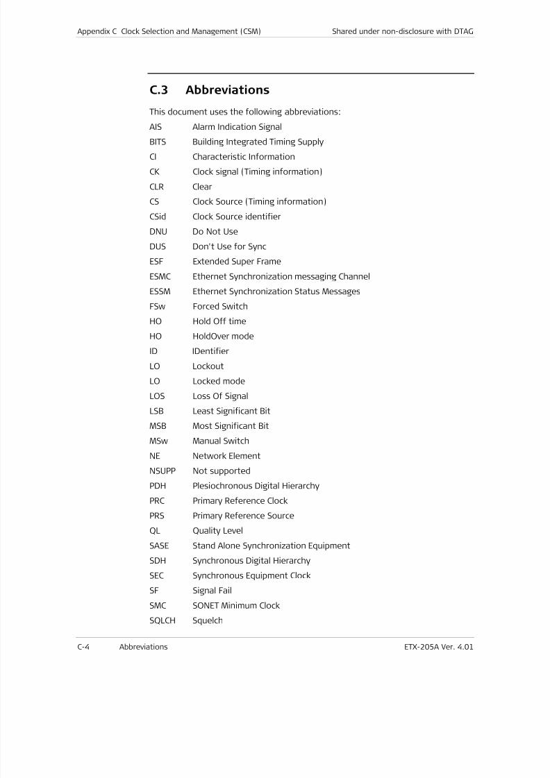
7/25/2019 Manual ETX-205A
http://slidepdf.com/reader/full/manual-etx-205a 360/409
Appendix C Clock Selection and Management (CSM) Shared under non-disclosure with DTAG
C-4 Abbreviations ETX-205A Ver. 4.01
C.3 Abbreviations
This document uses the following abbreviations:
AIS Alarm Indication SignalBITS Building Integrated Timing Supply
CI Characteristic Information
CK Clock signal (Timing information)
CLR Clear
CS Clock Source (Timing information)
CSid Clock Source identifier
DNU Do Not Use
DUS Don't Use for Sync
ESF Extended Super Frame
ESMC Ethernet Synchronization messaging Channel
ESSM Ethernet Synchronization Status Messages
FSw Forced Switch
HO Hold Off time
HO HoldOver mode
ID IDentifier
LO Lockout
LO Locked mode
LOS Loss Of Signal
LSB Least Significant Bit
MSB Most Significant Bit
MSw Manual Switch
NE Network Element
NSUPP Not supported
PDH Plesiochronous Digital Hierarchy
PRC Primary Reference Clock
PRS Primary Reference SourceQL Quality Level
SASE Stand Alone Synchronization Equipment
SDH Synchronous Digital Hierarchy
SEC Synchronous Equipment Clock
SF Signal Fail
SMC SONET Minimum Clock
SQLCH Squelch
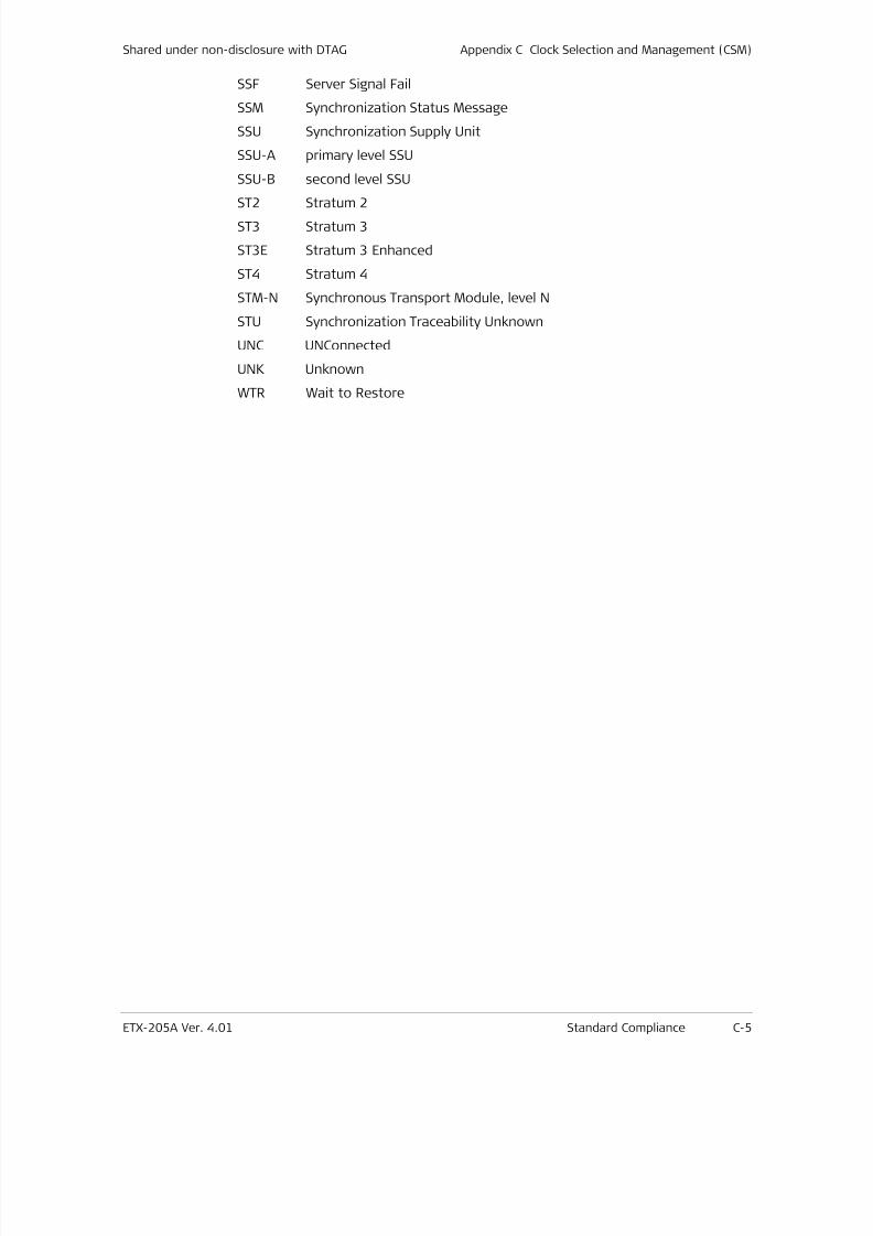
7/25/2019 Manual ETX-205A
http://slidepdf.com/reader/full/manual-etx-205a 361/409
Shared under non-disclosure with DTAG Appendix C Clock Selection and Management (CSM)
ETX-205A Ver. 4.01 Standard Compliance C-5
SSF Server Signal Fail
SSM Synchronization Status Message
SSU Synchronization Supply Unit
SSU-A primary level SSU
SSU-B second level SSU
ST2 Stratum 2ST3 Stratum 3
ST3E Stratum 3 Enhanced
ST4 Stratum 4
STM-N Synchronous Transport Module, level N
STU Synchronization Traceability Unknown
UNC UNConnected
UNK Unknown
WTR Wait to Restore
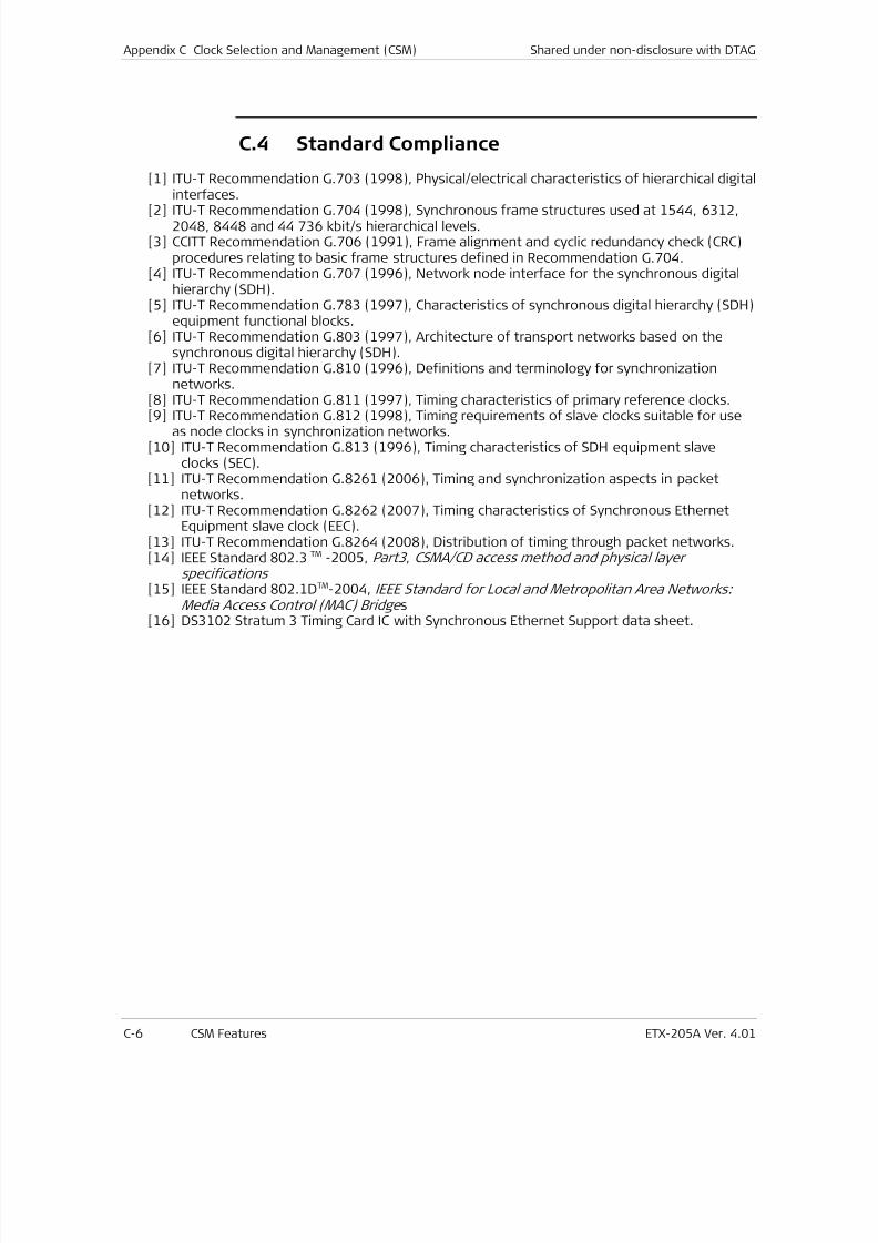
7/25/2019 Manual ETX-205A
http://slidepdf.com/reader/full/manual-etx-205a 362/409
Appendix C Clock Selection and Management (CSM) Shared under non-disclosure with DTAG
C-6 CSM Features ETX-205A Ver. 4.01
C.4 Standard Compliance
[1] ITU-T Recommendation G.703 (1998), Physical/electrical characteristics of hierarchical digitalinterfaces.
[2] ITU-T Recommendation G.704 (1998), Synchronous frame structures used at 1544, 6312,2048, 8448 and 44 736 kbit/s hierarchical levels.
[3] CCITT Recommendation G.706 (1991), Frame alignment and cyclic redundancy check (CRC)procedures relating to basic frame structures defined in Recommendation G.704.
[4] ITU-T Recommendation G.707 (1996), Network node interface for the synchronous digitalhierarchy (SDH).
[5] ITU-T Recommendation G.783 (1997), Characteristics of synchronous digital hierarchy (SDH)equipment functional blocks.
[6] ITU-T Recommendation G.803 (1997), Architecture of transport networks based on thesynchronous digital hierarchy (SDH).
[7] ITU-T Recommendation G.810 (1996), Definitions and terminology for synchronizationnetworks.
[8] ITU-T Recommendation G.811 (1997), Timing characteristics of primary reference clocks.
[9] ITU-T Recommendation G.812 (1998), Timing requirements of slave clocks suitable for useas node clocks in synchronization networks.
[10] ITU-T Recommendation G.813 (1996), Timing characteristics of SDH equipment slaveclocks (SEC).
[11] ITU-T Recommendation G.8261 (2006), Timing and synchronization aspects in packetnetworks.
[12] ITU-T Recommendation G.8262 (2007), Timing characteristics of Synchronous EthernetEquipment slave clock (EEC).
[13] ITU-T Recommendation G.8264 (2008), Distribution of timing through packet networks.[14] IEEE Standard 802.3 TM -2005, Part3 , CSMA/CD access method and physical layer
specifications [15] IEEE Standard 802.1DTM-2004, IEEE Standard for Local and Metropolitan Area Networks:
Media Access Control (MAC) Bridge s
[16] DS3102 Stratum 3 Timing Card IC with Synchronous Ethernet Support data sheet.
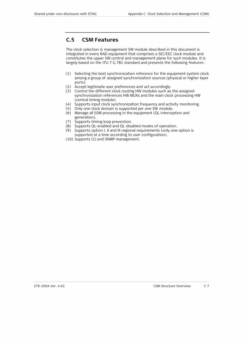
7/25/2019 Manual ETX-205A
http://slidepdf.com/reader/full/manual-etx-205a 363/409
Shared under non-disclosure with DTAG Appendix C Clock Selection and Management (CSM)
ETX-205A Ver. 4.01 CSM Structure Overview C-7
C.5 CSM Features
The clock selection & management SW module described in this document isintegrated in every RAD equipment that comprises a SEC/EEC clock module and
constitutes the upper SW control and management plane for such modules. It islargely based on the ITU-T G.781 standard and presents the following features:
(1) Selecting the best synchronization reference for the equipment system clockamong a group of assigned synchronization sources (physical or higher-layerports).
(2) Accept legitimate user preferences and act accordingly.(3) Control the different clock routing HW modules such as the assigned
synchronization references HW MUXs and the main clock processing HW(central timing module).
(4) Supports input clock synchronization frequency and activity monitoring.(5) Only one clock domain is supported per one SW module.
(6) Manage all SSM processing in the equipment (QL interception andgeneration).(7) Supports timing loop prevention.(8) Supports QL-enabled and QL-disabled modes of operation.(9) Supports option I, II and III regional requirements (only one option is
supported at a time according to user configuration).(10) Supports CLI and SNMP management.
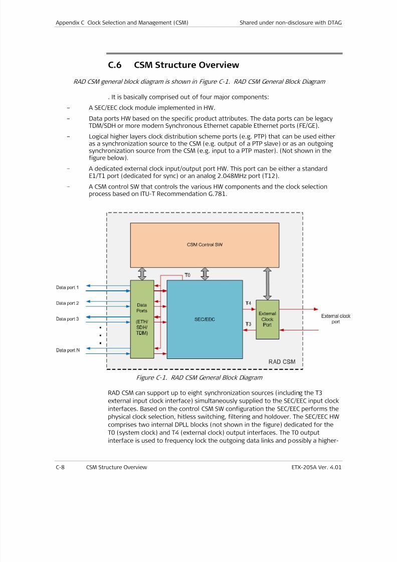
7/25/2019 Manual ETX-205A
http://slidepdf.com/reader/full/manual-etx-205a 364/409
Appendix C Clock Selection and Management (CSM) Shared under non-disclosure with DTAG
C-8 CSM Structure Overview ETX-205A Ver. 4.01
C.6 CSM Structure Overview
RAD CSM general block diagram is shown in Figure C-1. RAD CSM General Block Diagram
. It is basically comprised out of four major components:
– A SEC/EEC clock module implemented in HW.
– Data ports HW based on the specific product attributes. The data ports can be legacyTDM/SDH or more modern Synchronous Ethernet capable Ethernet ports (FE/GE).
– Logical higher layers clock distribution scheme ports (e.g. PTP) that can be used eitheras a synchronization source to the CSM (e.g. output of a PTP slave) or as an outgoingsynchronization source from the CSM (e.g. input to a PTP master). (Not shown in thefigure below).
– A dedicated external clock input/output port HW. This port can be either a standardE1/T1 port (dedicated for sync) or an analog 2.048MHz port (T12).
– A CSM control SW that controls the various HW components and the clock selectionprocess based on ITU-T Recommendation G.781.
Figure C-1. RAD CSM General Block Diagram
RAD CSM can support up to eight synchronization sources (including the T3
external input clock interface) simultaneously supplied to the SEC/EEC input clock
interfaces. Based on the control CSM SW configuration the SEC/EEC performs the
physical clock selection, hitless switching, filtering and holdover. The SEC/EEC HW
comprises two internal DPLL blocks (not shown in the figure) dedicated for the
T0 (system clock) and T4 (external clock) output interfaces. The T0 output
interface is used to frequency lock the outgoing data links and possibly a higher-

7/25/2019 Manual ETX-205A
http://slidepdf.com/reader/full/manual-etx-205a 365/409
Shared under non-disclosure with DTAG Appendix C Clock Selection and Management (CSM)
ETX-205A Ver. 4.01 Detailed Description C-9
layer clock distribution function (e.g. PTP master), while the T4 output interface is
used to frequency lock the external clock output port.
The CSM control SW runs all the G.781 based attributes such as the clock
selection algorithms, external user commands etc. It receives and transmits
Quality Level (QL) and Server Signal Fail (SSF) information from/to the relevant
data and external clock ports. It is also responsible for correctly configuring the
SEC/EEC according to the relevant standards and user preferences (e.g. G.8262option I…).
7/25/2019 Manual ETX-205A
http://slidepdf.com/reader/full/manual-etx-205a 366/409
Appendix C Clock Selection and Management (CSM) Shared under non-disclosure with DTAG
C-10 Detailed Description ETX-205A Ver. 4.01
C.7 Detailed Description
Clock Domains
The CSM module supports one clock domain (one primary long-term frequency
source) only. In products that require to support multiple clock domains (e.g. to
support multiple service providers, each having its own primary long-term
frequency source), multiple instances of the CSM module are required.
The clock domain ID shall be configured by the user using the following CLI
command:
configure >system>clock> domain <id> // <id> - domain number
7/25/2019 Manual ETX-205A
http://slidepdf.com/reader/full/manual-etx-205a 367/409
Shared under non-disclosure with DTAG Appendix C Clock Selection and Management (CSM)
ETX-205A Ver. 4.01 Detailed Description C-11
Supported Physical Synchronization Interfaces
Synchronization trails can be carried through the network by a number ofinterfaces. The following physical synchronization interfaces are supported:
Option I synchronization networking
Traffic interfaces:
• 2048 kHz (T12)1;
• 2048 kbit/s (E12+P12s);
Dedicated sync interfaces:
• 155 520 kbit/s (OS1 (or ES1)+RS1+MS1);
• 2048 kbit/s (E12+P12s)
• 100 000 kbit/s (ETY2[+ETH])
• 1 000 000 kbit/s (ETY3[+ETH])
• 10 000 000 kbit/s (ETY4[+ETH]).
Note: ETYn synchronization interfaces are full duplex ones with continuous bit
stream, as specified in G.8262.
Option II synchronization networking
Traffic interfaces:
• 1544 kbit/s (E11+P11s);• 155 520 kbit/s (OS1 (or ES1)+RS1+MS1);
• 1544 kbit/s (E11+P11s)
• 100 000 kbit/s (ETY2[+ETH])
• 1 000 000 kbit/s (ETY3[+ETH])
• 10 000 000 kbit/s (ETY4[+ETH]).
Note: ETYn synchronization interfaces are full duplex ones with continuous bit
stream, as specified in G.8262.
Option III synchronization networking
Traffic interfaces:
• 155 520 kbit/s (OS1 (or ES1)+RS1+MS1)
1 For more information regarding the terms in brackets see ITU-TG.703/G.704/G.781.
7/25/2019 Manual ETX-205A
http://slidepdf.com/reader/full/manual-etx-205a 368/409
Appendix C Clock Selection and Management (CSM) Shared under non-disclosure with DTAG
C-12 Detailed Description ETX-205A Ver. 4.01
• 100 000 kbit/s (ETY2[+ETH])
• 1 000 000 kbit/s (ETY3[+ETH])
• 10 000 000 kbit/s (ETY4[+ETH]).
Note: ETYn synchronization interfaces are full duplex ones with continuous bit
stream, as specified in G.8262.
STM-N
The STM-N transport signals carry (in addition to the payload) reference timinginformation and an indication of the quality level of the source generating thistiming information, via the Synchronization Status Message (SSM) as defined inRecommendation G.707.
2 Mbit/s (E1)The 2 Mbit/s transport signals may carry (in addition to the payload) referencetiming information.
The 2 Mbit/s timing reference signals (without payload) carry reference timinginformation to specific synchronization ports.
Both signals can carry an indication of the quality level of the source generatingthe timing information via the SSM as specified in Recommendation G.704.
2 MHz (T12)
Synchronization can be carried through 2 MHz signals to specific synchronizationports (so called station clock ports). This signal does not carry an indication ofthe quality level of the source generating the timing information.
1.5 Mbit/s (T1)
The 1.5 Mbit/s transport signals may carry (in addition to the payload) referencetiming information.
The 1.5 Mbit/s timing reference signals (without payload) carry reference timinginformation to specific synchronization ports.
Both signals can carry an indication of the quality level of the source generating
the timing information via the SSM transported within the 1544 kbit/s signal'sExtended Super Frame (ESF) Data Link (DL) as specified in RecommendationG.704.
100 Mbit/s, 1 Gbit/s, 10 Gbit/s
The 802.3 transport signals may carry (in addition to the payload) referencetiming information and an indication of the quality level of the source generatingthis timing information, via the Synchronization Status Message (SSM) as definedin ITU-T Recommendation G.8264.
7/25/2019 Manual ETX-205A
http://slidepdf.com/reader/full/manual-etx-205a 369/409
Shared under non-disclosure with DTAG Appendix C Clock Selection and Management (CSM)
ETX-205A Ver. 4.01 Detailed Description C-13
Note: Equipment developed prior to this first revision of the Recommendation
may not be able to carry reference timing information and/or support SSM via its
802.3 interfaces.
Note: It is possible that equipment is equipped with both non-synchronous andsynchronous 802.3 interfaces as defined in G.8264. Non-synchronous 802.3
interfaces are excluded from the synchronization distribution process.
The relevant synchronization input/output ports (type and ID) that are to take
part in the clock selection process are user configured using the following CLI
command:
configure >system>clock>domain (id)#[no] source <src-id> type
[<id>] [port type <port-index>]
// type – domain <domain-id>| rx-port port-type
<port-index>| station <station-id> | recovered<recovered-id>.
// rx-port port-type – E1, T1, Ethernet, SDH/SONET.
Note: Further details regarding the specific CLI structure may be found in
Chapter 5 .
7/25/2019 Manual ETX-205A
http://slidepdf.com/reader/full/manual-etx-205a 370/409
Appendix C Clock Selection and Management (CSM) Shared under non-disclosure with DTAG
C-14 Detailed Description ETX-205A Ver. 4.01
Clock-Source Quality Levels (QL) Supported
Clock-source quality-level definitions
SDH and packet transport networks throughout the world are based on differentsynchronization philosophies. Those differences are identified as three Options: I,
II, and III in the relevant standards and are all supported by the CSM SW module.
The relevant network option shall be configured by the user using the following
CLI command:
configure >system>clock>domain (id)# sync-network type-1 |type-2 | type-3 // default type-2
A change in the sync-network Type configuration can only take place if no clocksources are configured. An attempt to change the sync-network Type when oneor more clock sources are configured in the system will result in the following
error message:‘Existing sources should be removed first’
Thus, before changing the sync-network Type, the user must delete all configuredclock sources.
Option I synchronization networking
The following clock source quality levels are defined in the CSM synchronizationprocess of Option I network corresponding to 4 levels of synchronization quality(based in ITU-T Recommendation G.803).
QL-PRC: This synchronization trail transports a timing qualitygenerated by a Primary Reference Clock that isdefined in Recommendation G.811.
QL-SSU-A: This synchronization trail transports a timing qualitygenerated by Types I or V slave clock that is definedin Recommendation G.812.
QL-SSU-B: This synchronization trail transports a timing qualitygenerated by a Type VI slave clock that is defined inRecommendation G.812.
QL-SEC: This synchronization trail transports a timing qualitygenerated by a Synchronous Equipment Clock (SEC)
that is defined in Recommendation G.813 or G.8262,Option I.
QL-DNU: This signal should not be used for synchronization.
Option II synchronization networking
Clock source quality levels of Option II networks have been expanded from 7levels to 9 levels. The 7 quality level set is referred to as First generation and the
7/25/2019 Manual ETX-205A
http://slidepdf.com/reader/full/manual-etx-205a 371/409
Shared under non-disclosure with DTAG Appendix C Clock Selection and Management (CSM)
ETX-205A Ver. 4.01 Detailed Description C-15
new 9 quality level set is referred to as Second generation. First generationquality levels are a subset of Second generation.
Note: RAD equipment is always defined as a second generation equipment.
The following clock source quality levels are defined in the CSM synchronizationselection process of Option II network corresponding to Second generation.
QL-PRS: PRS traceable (Recommandation G.811).
QL-STU: Synchronized – Traceability Unknown.
QL-ST2: Traceable to Stratum 2 (Recommendation G.812, Type II).
QL-TNC: Traceable to Transit Node Clock (Recommendation G.812, TypeV).
QL-ST3E: Traceable to Stratum 3E (Recommendation G.812, Type III).
QL-ST3: Traceable to Stratum 3 (Recommendation G.812, Type IV).
QL-SMC: Traceable to SONET Clock Self Timed (Recommendation G.813 orG.8262, Option II).
QL-ST4: Traceable to Stratum 4 Freerun (only applicable to 1.5 Mbit/ssignals).
QL-PROV: Provisionable by the Network Operator.
QL-DUS: This signal should not be used for synchronization.
Option III synchronization networking
The following clock source quality levels are defined in the synchronizationprocess of Option III SDH network corresponding to 2 levels of synchronization
quality.
QL-UNK: This synchronization trail transports a timing qualitygenerated by an unknown clock source. It is at least ofquality SSU.
QL-SEC: This synchronization trail transports a timing qualitygenerated by a Synchronous Equipment Clock (SEC) that isdefined in ITU-T Recommendation G.813 or G.8262, Option I.
External synchronization interface output (T4) squelchingThe CSM module supports ‘squelching’ of the external synchronization interfaceoutput. The first purpose of the "squelch" function is to prevent transmission ofa timing signal with a quality that is lower than the quality of the clock in thereceiving network element or SASE. It is also used for the prevention of timingloops (see 0).
Squelching is done according to the user configured QL_minimum value, bycomparing this user configured value to the reported quality level of the currentselected synchronization source.
7/25/2019 Manual ETX-205A
http://slidepdf.com/reader/full/manual-etx-205a 372/409
Appendix C Clock Selection and Management (CSM) Shared under non-disclosure with DTAG
C-16 Detailed Description ETX-205A Ver. 4.01
Note: Squelching (signal cutoff) is only applicable for 2.048 MHz (T12) clock
interfaces. In case 2.048 Kb/s (E1) or 1.544 Kb/s (T1) are used, upon a
‘squelching’ event the interface would start transmitting AIS.
Supported hierarchy of clock-sources quality levels (QL)
The following tables define the QL hierarchy.
Option I synchronization networking
Table C-1. Hierarchy of quality levels in Option I
Quality Level Order
QL-PRC highest
QL-SSU-A |
QL-SSU-B |
QL-SEC |
QL-DNU |
QL-INVx, -FAILED, -UNC, -NSUPP lowest
Note: The quality levels QL-INVx, QL-FAILED, QL-UNC and QL-NSUPP are internal
QLs inside the NE and are never generated at an output port.
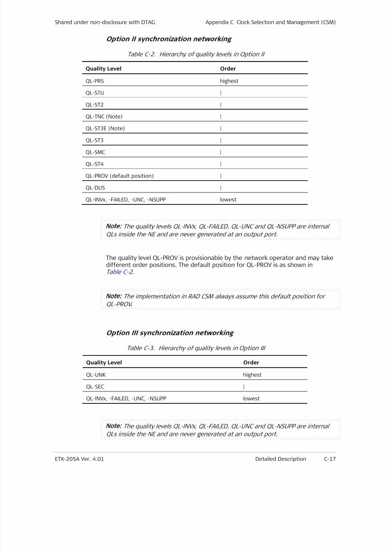
7/25/2019 Manual ETX-205A
http://slidepdf.com/reader/full/manual-etx-205a 373/409
Shared under non-disclosure with DTAG Appendix C Clock Selection and Management (CSM)
ETX-205A Ver. 4.01 Detailed Description C-17
Option II synchronization networking
Table C-2. Hierarchy of quality levels in Option II
Quality Level Order
QL-PRS highest
QL-STU |
QL-ST2 |
QL-TNC (Note) |
QL-ST3E (Note) |
QL-ST3 |
QL-SMC |
QL-ST4 |
QL-PROV (default position) |
QL-DUS |
QL-INVx, -FAILED, -UNC, -NSUPP lowest
Note: The quality levels QL-INVx, QL-FAILED, QL-UNC and QL-NSUPP are internal
QLs inside the NE and are never generated at an output port.
The quality level QL-PROV is provisionable by the network operator and may takedifferent order positions. The default position for QL-PROV is as shown inTable C-2 .
Note: The implementation in RAD CSM always assume this default position for
QL-PROV .
Option III synchronization networking
Table C-3. Hierarchy of quality levels in Option III
Quality Level Order
QL-UNK highest
QL-SEC |
QL-INVx, -FAILED, -UNC, -NSUPP lowest
Note: The quality levels QL-INVx, QL-FAILED, QL-UNC and QL-NSUPP are internal
QLs inside the NE and are never generated at an output port.
7/25/2019 Manual ETX-205A
http://slidepdf.com/reader/full/manual-etx-205a 374/409
Appendix C Clock Selection and Management (CSM) Shared under non-disclosure with DTAG
C-18 Detailed Description ETX-205A Ver. 4.01
Forcing and defaulting of clock-source quality-levels
For synchronization source signals/interfaces not supporting SSMtransport/processing, it is possible to force the quality level to a fixed provisionedvalue. This allows using these signals/interfaces as synchronization sources in anautomatic reference selection process operating in QL-enabled mode.
Forcing of quality levels is used for new equipment operating in QL-enabled modein order to:
• interwork with old equipment not supporting SSM generation
• interwork with new equipment operating in QL-disabled mode;
• select interfaces not supporting SSM processing;
• select signals for which SSM is not defined (e.g. 2 MHz).
Note: It should be however noted that valid SSM synchronization sources can alsobe overwritten using the ‘Force QL’ procedure.
In RAD CSM, when working in QL-enabled mode, the user must configure (‘force’)a specific QL level (see 0) for all the ingress synchronization interfaces (assignedsync sources) that does not support SSM (outputting the default QL-NSUPP).
A synchronization source issuing signal fail (SSF) cannot be QL overwritten byuser configuration (QL_FAILED will always be distributed to the selectionalgorithm).
Option I synchronization networking
The quality level of the input signal (STM-N, 2 Mbit/s, 2 MHz) can be forced toeither QL-PRC, QL-SSU-A, QL-SSU-B or QL-SEC.
Option II synchronization networking
The quality level of the input signal can be forced to either QL-PRS, QL-STU,QL-ST2, QL-TNC, QL-ST3E, QL-ST3, QL-SMC, QL-ST4, QL-PROV or QL-DUS.
Option III synchronization networking
The quality level of the input signal can be forced to either QL-UNK or QL-SEC.

7/25/2019 Manual ETX-205A
http://slidepdf.com/reader/full/manual-etx-205a 375/409
Shared under non-disclosure with DTAG Appendix C Clock Selection and Management (CSM)
ETX-205A Ver. 4.01 Detailed Description C-19
Synchronization Status Messages (SSM)
The following supported signals have a four-bit SSM channel defined:
• STM-N (N = 1, 4, 16): bits 5 to 8 of the byte S1 (called SSMB,Synchronization Status Message Byte) of the multiplex section
overhead as defined in Recommendation G.707. • 2 Mbit/s octet structured according to Recommendation G.704: bits
Sax1 to Sax4 (x = 4, 5, 6, 7, or 8) of TS0.
• 1.5 Mbit/s octet structured according to 2.1/G.704.
• 100 Mbit/s, 1 Gbit/s, 10 Gbit/s as defined in IEEE Std. 802.3: 4-bit SSMfield in the SSM PDU as defined in Recommendation G.8264.
SSM message sets
Option I synchronization networking
Five SSM codes are defined to represent clock source QL as listed below:
• code 0010 (Quality PRC) means that the source of the trail is a PRCclock (Recommendation G.811);
• code 0100 (Quality SSU-A), means that the source of the trail is a Type I or V
SSU clock as defined in Recommendation G.812;
• code 1000 (Quality SSU-B), means that the source of the trail is a Type VI
SSU clock (Recommendation G.812);
• code 1011 (Quality SEC), means that the source of the trail is a SEC clock
(Recommendation G.813 or G.8262, Option I);
•
code 1111 (quality DNU), means that the signal carrying this SSM shall not beused for synchronization because a timing loop situation could result if it is
used.
Option II synchronization networking
Nine SSM codes are defined to represent clock source QL as listed below on STM-N signals:
• code 0001 (Quality PRS) means that the source of the trail is a PRS clock
(Recommendation G.811);
• code 0000 (Quality STU) means that the signal does not carry the QL
message of the source of the trail;
• code 0111 (Quality ST2), means that the source of the trail is a Stratum 2
clock (Recommendation G.812, Type II);
• code 0100 (Quality TNC), means that the source of the trail is a Transit Node
Clock (Recommendation G.812, Type V);
• code 1101 (Quality ST3E), means that the source of the trail is a stratum 3E
clock (Recommendation G.812, Type III);
• code 1010 (Quality ST3), means that the source of the trail is a stratum 3
clock (Recommendation G.812, Type IV);
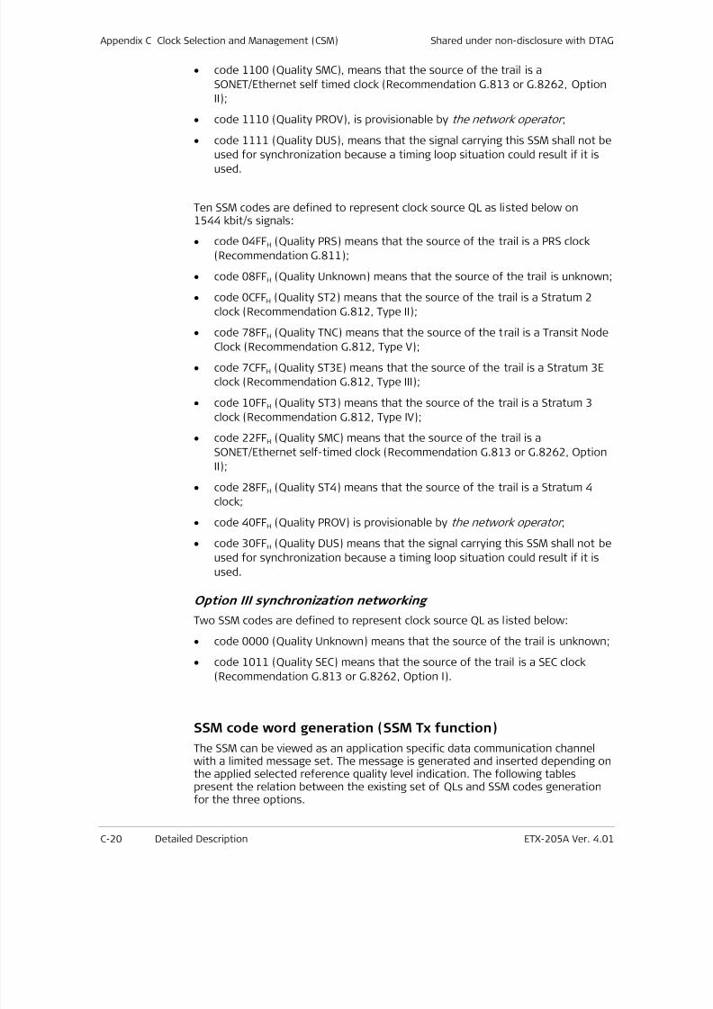
7/25/2019 Manual ETX-205A
http://slidepdf.com/reader/full/manual-etx-205a 376/409
Appendix C Clock Selection and Management (CSM) Shared under non-disclosure with DTAG
C-20 Detailed Description ETX-205A Ver. 4.01
• code 1100 (Quality SMC), means that the source of the trail is a
SONET/Ethernet self timed clock (Recommendation G.813 or G.8262, Option
II);
• code 1110 (Quality PROV), is provisionable by the network operator ;
• code 1111 (Quality DUS), means that the signal carrying this SSM shall not be
used for synchronization because a timing loop situation could result if it is
used.
Ten SSM codes are defined to represent clock source QL as listed below on1544 kbit/s signals:
• code 04FFH (Quality PRS) means that the source of the trail is a PRS clock
(Recommendation G.811);
• code 08FFH (Quality Unknown) means that the source of the trail is unknown;
• code 0CFFH (Quality ST2) means that the source of the trail is a Stratum 2
clock (Recommendation G.812, Type II);
•
code 78FFH (Quality TNC) means that the source of the trail is a Transit NodeClock (Recommendation G.812, Type V);
• code 7CFFH (Quality ST3E) means that the source of the trail is a Stratum 3E
clock (Recommendation G.812, Type III);
• code 10FFH (Quality ST3) means that the source of the trail is a Stratum 3
clock (Recommendation G.812, Type IV);
• code 22FFH (Quality SMC) means that the source of the trail is a
SONET/Ethernet self-timed clock (Recommendation G.813 or G.8262, Option
II);
• code 28FFH (Quality ST4) means that the source of the trail is a Stratum 4
clock;
• code 40FFH (Quality PROV) is provisionable by the network operator ;
• code 30FFH (Quality DUS) means that the signal carrying this SSM shall not be
used for synchronization because a timing loop situation could result if it is
used.
Option III synchronization networking
Two SSM codes are defined to represent clock source QL as listed below:
• code 0000 (Quality Unknown) means that the source of the trail is unknown;
• code 1011 (Quality SEC) means that the source of the trail is a SEC clock
(Recommendation G.813 or G.8262, Option I).
SSM code word generation (SSM Tx function)
The SSM can be viewed as an application specific data communication channelwith a limited message set. The message is generated and inserted depending onthe applied selected reference quality level indication. The following tablespresent the relation between the existing set of QLs and SSM codes generationfor the three options.
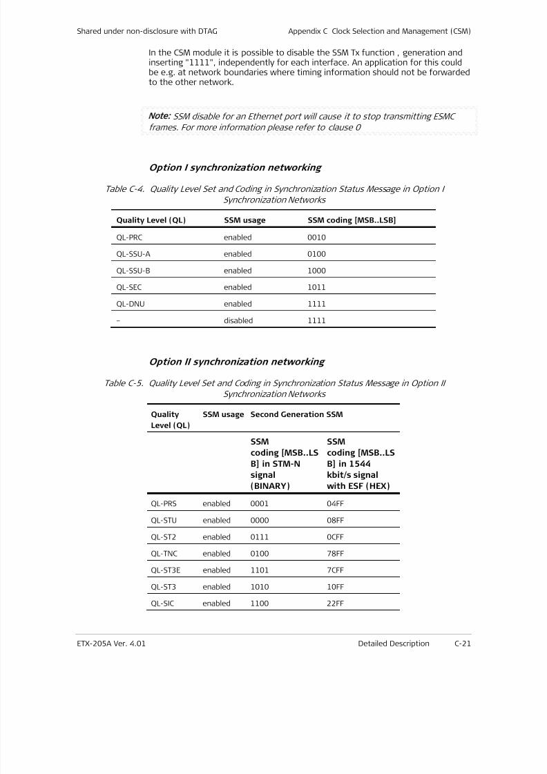
7/25/2019 Manual ETX-205A
http://slidepdf.com/reader/full/manual-etx-205a 377/409
Shared under non-disclosure with DTAG Appendix C Clock Selection and Management (CSM)
ETX-205A Ver. 4.01 Detailed Description C-21
In the CSM module it is possible to disable the SSM Tx function , generation andinserting "1111", independently for each interface. An application for this couldbe e.g. at network boundaries where timing information should not be forwardedto the other network.
Note: SSM disable for an Ethernet port will cause it to stop transmitting ESMC
frames. For more information please refer to clause 0
Option I synchronization networking
Table C-4. Quality Level Set and Coding in Synchronization Status Message in Option I
Synchronization Networks
Quality Level (QL) SSM usage SSM coding [MSB..LSB]
QL-PRC enabled 0010
QL-SSU-A enabled 0100
QL-SSU-B enabled 1000
QL-SEC enabled 1011
QL-DNU enabled 1111
– disabled 1111
Option II synchronization networking
Table C-5. Quality Level Set and Coding in Synchronization Status Message in Option IISynchronization Networks
Quality
Level (QL)
SSM usage Second Generation SSM
SSM
coding [MSB..LS
B] in STM-N
signal
(BINARY)
SSM
coding [MSB..LS
B] in 1544
kbit/s signal
with ESF (HEX)
QL-PRS enabled 0001 04FF
QL-STU enabled 0000 08FF
QL-ST2 enabled 0111 0CFF
QL-TNC enabled 0100 78FF
QL-ST3E enabled 1101 7CFF
QL-ST3 enabled 1010 10FF
QL-SIC enabled 1100 22FF
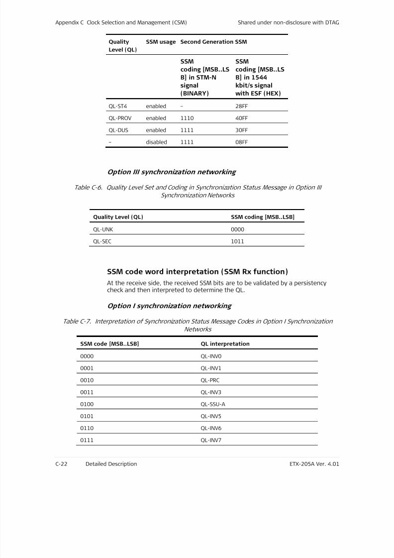
7/25/2019 Manual ETX-205A
http://slidepdf.com/reader/full/manual-etx-205a 378/409
Appendix C Clock Selection and Management (CSM) Shared under non-disclosure with DTAG
C-22 Detailed Description ETX-205A Ver. 4.01
Quality
Level (QL)
SSM usage Second Generation SSM
SSM
coding [MSB..LS
B] in STM-N
signal
(BINARY)
SSM
coding [MSB..LS
B] in 1544
kbit/s signal
with ESF (HEX)
QL-ST4 enabled – 28FF
QL-PROV enabled 1110 40FF
QL-DUS enabled 1111 30FF
– disabled 1111 08FF
Option III synchronization networking
Table C-6. Quality Level Set and Coding in Synchronization Status Message in Option IIISynchronization Networks
Quality Level (QL) SSM coding [MSB..LSB]
QL-UNK 0000
QL-SEC 1011
SSM code word interpretation (SSM Rx function)
At the receive side, the received SSM bits are to be validated by a persistencycheck and then interpreted to determine the QL.
Option I synchronization networking
Table C-7. Interpretation of Synchronization Status Message Codes in Option I Synchronization
Networks
SSM code [MSB..LSB] QL interpretation
0000 QL-INV0
0001 QL-INV10010 QL-PRC
0011 QL-INV3
0100 QL-SSU-A
0101 QL-INV5
0110 QL-INV6
0111 QL-INV7
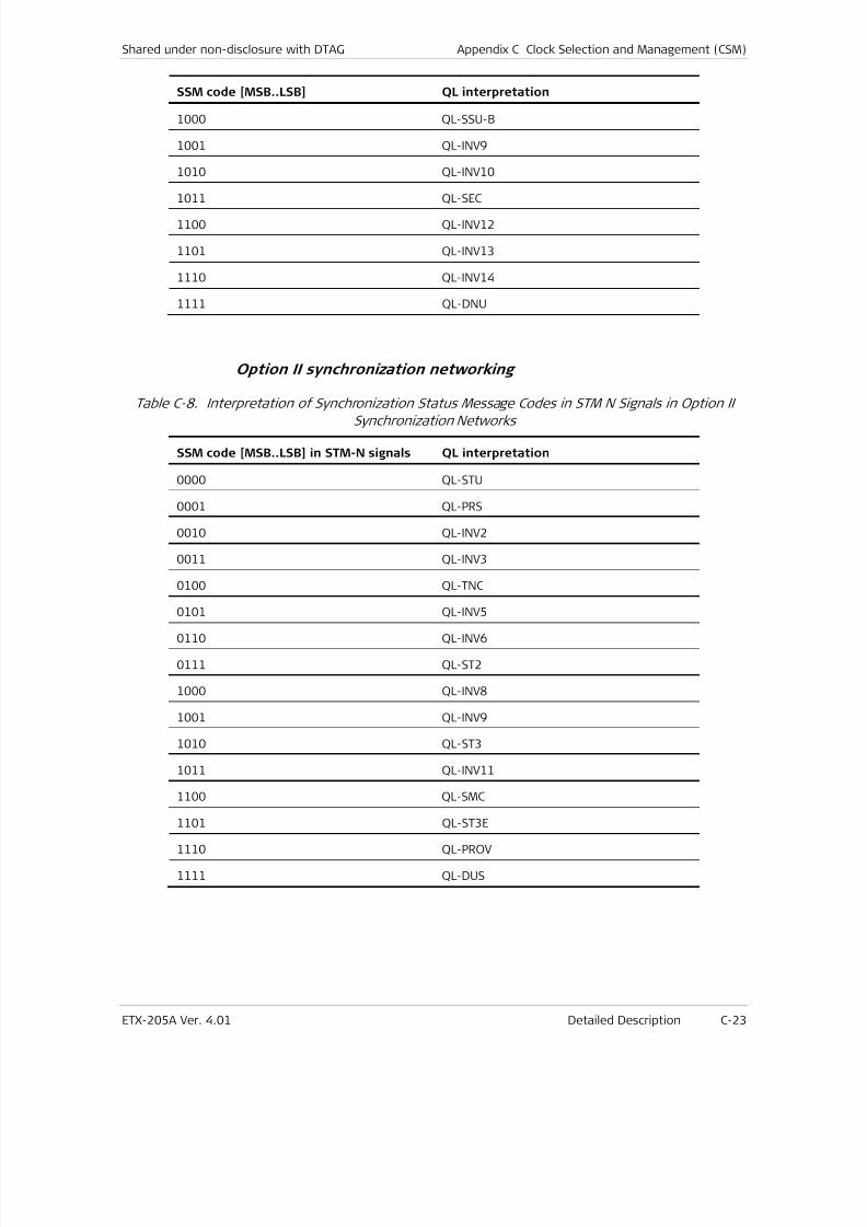
7/25/2019 Manual ETX-205A
http://slidepdf.com/reader/full/manual-etx-205a 379/409
Shared under non-disclosure with DTAG Appendix C Clock Selection and Management (CSM)
ETX-205A Ver. 4.01 Detailed Description C-23
SSM code [MSB..LSB] QL interpretation
1000 QL-SSU-B
1001 QL-INV9
1010 QL-INV10
1011 QL-SEC
1100 QL-INV12
1101 QL-INV13
1110 QL-INV14
1111 QL-DNU
Option II synchronization networking
Table C-8. Interpretation of Synchronization Status Message Codes in STM N Signals in Option IISynchronization Networks
SSM code [MSB..LSB] in STM-N signals QL interpretation
0000 QL-STU
0001 QL-PRS
0010 QL-INV2
0011 QL-INV3
0100 QL-TNC
0101 QL-INV5
0110 QL-INV6
0111 QL-ST2
1000 QL-INV8
1001 QL-INV9
1010 QL-ST3
1011 QL-INV11
1100 QL-SMC
1101 QL-ST3E
1110 QL-PROV
1111 QL-DUS
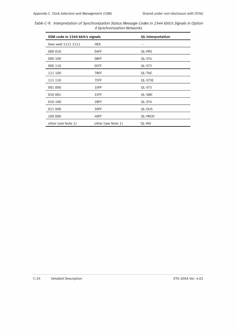
7/25/2019 Manual ETX-205A
http://slidepdf.com/reader/full/manual-etx-205a 380/409
Appendix C Clock Selection and Management (CSM) Shared under non-disclosure with DTAG
C-24 Detailed Description ETX-205A Ver. 4.01
Table C-9. Interpretation of Synchronization Status Message Codes in 1544 kbit/s Signals in Option
II Synchronization Networks
SSM code in 1544 kbit/s signals QL interpretation
0xxx xxx0 1111 1111 HEX --
000 010 04FF QL-PRS
000 100 08FF QL-STU
000 110 0CFF QL-ST2
111 100 78FF QL-TNC
111 110 7CFF QL-ST3E
001 000 10FF QL-ST3
010 001 22FF QL-SMC
010 100 28FF QL-ST4
011 000 30FF QL-DUS
100 000 40FF QL-PROV
other (see Note 1) other (see Note 1) QL-INV
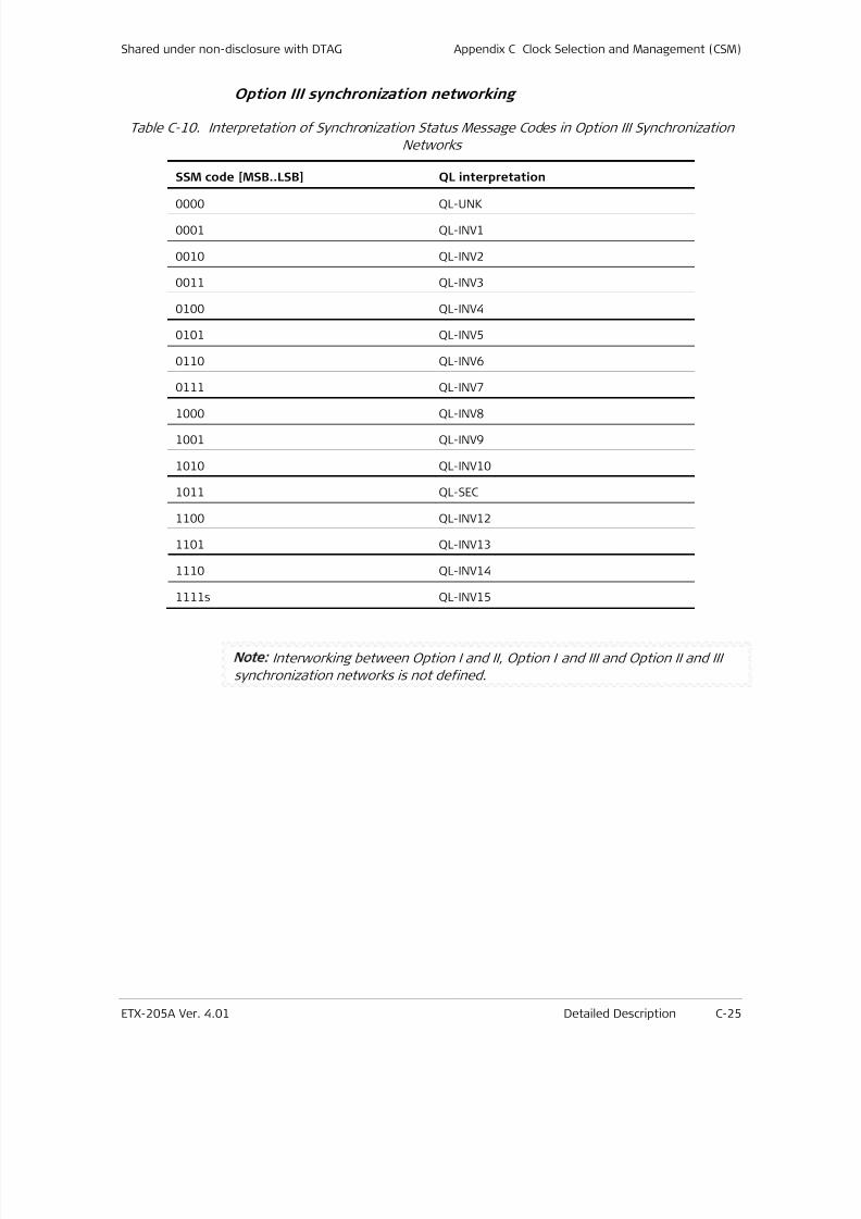
7/25/2019 Manual ETX-205A
http://slidepdf.com/reader/full/manual-etx-205a 381/409
Shared under non-disclosure with DTAG Appendix C Clock Selection and Management (CSM)
ETX-205A Ver. 4.01 Detailed Description C-25
Option III synchronization networking
Table C-10. Interpretation of Synchronization Status Message Codes in Option III Synchronization
Networks
SSM code [MSB..LSB] QL interpretation
0000 QL-UNK
0001 QL-INV1
0010 QL-INV2
0011 QL-INV3
0100 QL-INV4
0101 QL-INV5
0110 QL-INV6
0111 QL-INV7
1000 QL-INV8
1001 QL-INV9
1010 QL-INV10
1011 QL-SEC
1100 QL-INV12
1101 QL-INV13
1110 QL-INV14
1111s QL-INV15
Note: Interworking between Option I and II, Option I and III and Option II and III
synchronization networks is not defined.
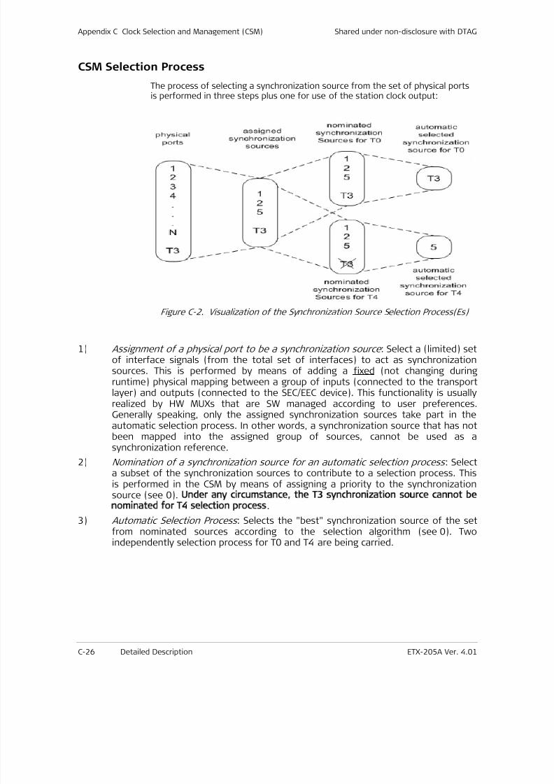
7/25/2019 Manual ETX-205A
http://slidepdf.com/reader/full/manual-etx-205a 382/409
Appendix C Clock Selection and Management (CSM) Shared under non-disclosure with DTAG
C-26 Detailed Description ETX-205A Ver. 4.01
CSM Selection Process
The process of selecting a synchronization source from the set of physical portsis performed in three steps plus one for use of the station clock output:
Figure C-2. Visualization of the Synchronization Source Selection Process(Es)
1) Assignment of a physical port to be a synchronization source : Select a (limited) setof interface signals (from the total set of interfaces) to act as synchronizationsources. This is performed by means of adding a fixed (not changing duringruntime) physical mapping between a group of inputs (connected to the transport
layer) and outputs (connected to the SEC/EEC device). This functionality is usuallyrealized by HW MUXs that are SW managed according to user preferences.Generally speaking, only the assigned synchronization sources take part in theautomatic selection process. In other words, a synchronization source that has notbeen mapped into the assigned group of sources, cannot be used as asynchronization reference.
2) Nomination of a synchronization source for an automatic selection process : Selecta subset of the synchronization sources to contribute to a selection process. Thisis performed in the CSM by means of assigning a priority to the synchronizationsource (see 0). Under any circumstance, the T3 synchronization source cannot be
nominated for T4 selection process.
3) Automatic Selection Process : Selects the "best" synchronization source of the setfrom nominated sources according to the selection algorithm (see 0). Twoindependently selection process for T0 and T4 are being carried.
7/25/2019 Manual ETX-205A
http://slidepdf.com/reader/full/manual-etx-205a 383/409
Shared under non-disclosure with DTAG Appendix C Clock Selection and Management (CSM)
ETX-205A Ver. 4.01 Detailed Description C-27
Signal Fail
RAD CSM supports three levels (or sources) of signal fail triggering:
1. Signal fail for a synchronization source is activated in case of defects
detected in the transport layers. In addition an unconnected synchronizationsignal has also signal fail active in order to allow correct processing in the QL
disabled mode.
2. Inclusion of specific synchronization failures conditions based on dedicated
detection mechanism embedded within the SEC/EEC device are also
supported. More specifically, RAD’s SEC/EEC implementation is capable of
detecting a large frequency deviation, beyond a pre-configured threshold, as
well as lack of activity on each one of the assigned synchronization sources.
Those alarm indications will be also used to issue a Server Singal Fail (SSF)
signal towards the CSM.
An SSF signal will be issued by the SEC/EEC HW in the following cases:
Activity alarm (leaky bucket mechanism). The configuration of the activity
detector is fixed and preconfigured for all RAD products.
10,000 ppm coarse frequency monitoring (fixed for all RAD products).
User configured HARD limit frequency monitoring. The user can configurea HARD frequency limit within the range of ±3.81 ppm to ±60.96 ppm in
0.01 ppm steps using the following CLI command:
configure >system>clock>domain (id)># max-frequency-deviation<value>
3. For Synchronous Ethernet ports, failing to receive a valid ESMC message for a
period of 5 seconds will immediately issue a signal fail indication.
In order to avoid reactions on short pulses or intermittent signal fail information,the signal fail information is passed through a hold-off and wait-to-restoreprocesses before it is considered by the selection process.
In QL enabled mode the QL of a synchronization source with active signal fail isset to QL-FAILED. The selection process will react to this QL value instead of thesignal fail signal in this mode.
When it comes to the user failure indications for a specific clock source, thepriority of presenting the specific SSF event cause will be as follows:
1. A problem reported by the PHY ( physical-fail)
2. Violation of the HARD frequency limit (monitoring-fail)
3. Lack of ESMC messages reception (if the interface is an Ethernet one) (esmc-
fail)
In other words, a violation of the HARD frequency limit would mask a concurrentESMC messages timeout indication. A problem reported from the PHY would mask

7/25/2019 Manual ETX-205A
http://slidepdf.com/reader/full/manual-etx-205a 384/409
Appendix C Clock Selection and Management (CSM) Shared under non-disclosure with DTAG
C-28 Detailed Description ETX-205A Ver. 4.01
both concurrent HARD frequency violation and ESMC messages timeoutindications.
It should be stressed again that only the user indication would be masked, notthe actual failure signal (SSF). Moreover, next versions of CSM will supportdedicated/independent user indications for each cause.

7/25/2019 Manual ETX-205A
http://slidepdf.com/reader/full/manual-etx-205a 385/409
Shared under non-disclosure with DTAG Appendix C Clock Selection and Management (CSM)
ETX-205A Ver. 4.01 Detailed Description C-29
Hold-Off and Wait-to-Restore Delays Support
Hold-Off Time
The hold-off time ensures that short activation of signal fail is not passed to theselection process.
In QL-disabled mode signal fail is active for the hold-off time before it is passedto the selection process.
In QL-enabled mode a QL value of QL-FAILED exists for the hold-off time before itis passed to the selection process. In the mean time the previous QL value ispassed to the selection process.
Note: Other QL values than QL-FAILED are passed to the selection process
immediately.
Separate hold-off timers are used for each input to a selection process(nominated source). The hold-off time is user configured within the range of 300ms to 1800 ms using the following CLI command:
configure >system>clock>domain (id)> source (src-id)# hold-off<seconds>
Wait-to-Restore Time
The wait to restore time ensures that a previous failed synchronization source isonly again considered as available by the selection process if it is fault free for acertain time.
In QL-disabled mode after deactivation of signal fail, it will remain false for thewait to restore time before signal fail false is passed to the selection process. Inthe meantime, signal fail true is passed to the selection process.
In QL-enabled mode after a change of the quality level from QL-FAILED to anyother value, the quality value QL-FAILED is maintained for the wait to restoretime before the new QL value is passed to the selection process. In themeantime, the quality level QL-FAILED is passed to the selection process.
Separate wait to restore timers are used for each input to a selection process(nominated source).
The wait to restore time is user configurable (user configuration) in the range of0 to 12 minutes in steps of 1 minute for all inputs of the selection process incommon using the following CLI command. The default value is 5 minutes.
configure >system>clock>domain (id)> source (src-id)#
wait-to-restore <seconds>
Each wait to restore timer can be cleared with a separate (user) Clear commandusing the CLI command shown below. If a wait to restore timer is cleared the newQL value (in QL-enabled mode), or signal fail value (in QL-disabled mode), isimmediately passed to the selection process.

7/25/2019 Manual ETX-205A
http://slidepdf.com/reader/full/manual-etx-205a 386/409
Appendix C Clock Selection and Management (CSM) Shared under non-disclosure with DTAG
C-30 Detailed Description ETX-205A Ver. 4.01
configure >system>clock>domain (id)> source (src-id)#
wait-to-restore-clear //command
A new WTR state status was added to the source/show status command togive the user more clarity regarding the current ‘WTR state’ of eachsynchronization source.
configure >system>clock>domain (id)> source (src-id)# show status
.
.
.
WTR State : Inactive | Running
7/25/2019 Manual ETX-205A
http://slidepdf.com/reader/full/manual-etx-205a 387/409
Shared under non-disclosure with DTAG Appendix C Clock Selection and Management (CSM)
ETX-205A Ver. 4.01 Detailed Description C-31
Synchronization Source Priorities
In order to define a preferred network synchronization flow, priority values areallocated to assigned synchronization sources within a network element (seeTable C-11).
Different priorities reflect a preference of one synchronization source over theother. Equal synchronization source priorities reflect that no preference existsbetween the synchronization sources.
Within the group of synchronization sources with equal priorities, the selectionprocess has a non-revertive behaviour.
Table C-11. Priority Order
Priority value Order
1 highest
2 |
3 |
: |
K lowest
Disable (no priority) Cannot be used for
clock selection T0/T4
Note: The priority value is not numerical ordered. The following relation is
present: "1" > "2" > "3" > .. >"K".
Note: The assigning of equal priorities to synchronization sources, in order to
allow for non-revertive operation, does not allow for a pre-defined initialization
state of known synchronization configuration following failure of a higher priority
source.
The CSM synchronization source ports priority is configured by the user using thefollowing CLI command:
configure >system>clock>domain (id)> source (src-id)#no priority <num> ock-
// If no option is chosen, then this source is not taken to theselection process
7/25/2019 Manual ETX-205A
http://slidepdf.com/reader/full/manual-etx-205a 388/409
Appendix C Clock Selection and Management (CSM) Shared under non-disclosure with DTAG
C-32 Detailed Description ETX-205A Ver. 4.01
External Commands
Several external commands are available to the user via the product’smanagement level (e.g. for maintenance purposes). These commands areindependent and have different impact on the selection processes.
The activation and deactivation of external commands associated with thesynchronization selection process are defined below. Furthermore, only one ofthese external commands is active at a time as per the selection process.
Clear command
A clear (CLR) command clears the forced switch and manual switch commands.
Forced switch #p command
A forced switch (FSw) to #p command can be used to override the currently
selected synchronization source, assuming the synchronization source #p isenabled.
The forced switch overrides the manual switch and a subsequent forced switchpre-empts the previous forced switch.
If the source selected by the forced switch command (#p) is disabled (using the‘no priority’ command), the forced switch command is automatically rejected. Theforced switch command can be cleared by the "clear" command.
Note: A forced switch command to a synchronization source #p, which is in the
SF state or has a QL of DNU in QL enabled mode, will result in the network
element entering holdover.
A new Force switch state status was added to the domain/show status command to give the user more clarity regarding the current ‘Force switch’ stateof the clock domain.
configure >system>clock>domain (id) # show status
.
.
.
Force Switch: InActive | Active
Manual switch #p command
A manual switch (MSw) to #p command selects the synchronization source #p,assuming it is enabled, , not in signal fail condition, and has a QL better thanDNU in QL enabled mode. Furthermore, in the QL enabled mode, a manual switchcan be performed only to a source which has the highest available QL. As such,these conditions have the effect that manual switching can only be used tooverride the assigned synchronization source priorities.
A manual switch request overrides a previous manual switch request.

7/25/2019 Manual ETX-205A
http://slidepdf.com/reader/full/manual-etx-205a 389/409
Shared under non-disclosure with DTAG Appendix C Clock Selection and Management (CSM)
ETX-205A Ver. 4.01 Detailed Description C-33
If the source selected by the manual switch command (#p) is in signal fail, or hasa QL of DNU or lower than one of the other source signals, the manual switchcommand is automatically rejected.
The manual switch command can be cleared by the "clear" command.
The following CLI commands allow the user to impose external commands on the
CSM:configure >system>clock>domain (id)# force < source-id >
configure >system>clock>domain (id)# manual < source-id >
configure >system>clock>domain (id)# clear
A new Manual switch state status was added to the domain/show status command to give the user more clarity regarding the current ‘Manual switch’state of the clock domain.
configure >system>clock>domain (id) # show status
.
.
. Manual Switch: InActive | Active
Force T4=T0 set command
A new ‘Force T4 to T0’ command has been added to this version of the CSM.
Activating this command will deactivate the T4 DPLL and will use the T0 DPLL to
feed both the T0 and T4 output clock paths.
configure >system>clock>domain (id)# [no] force-t4-as-t0//project dependent
7/25/2019 Manual ETX-205A
http://slidepdf.com/reader/full/manual-etx-205a 390/409
Appendix C Clock Selection and Management (CSM) Shared under non-disclosure with DTAG
C-34 Detailed Description ETX-205A Ver. 4.01
Automatic Reference Selection Process
One or more reference selection processes are operating independently to selectthe reference signal for the internal (system) clock (T0) and, where present, thestation clock output(s) (T4).
The selection process(es) can work in two distinct modes: QL-enabled orQL-disabled. If multiple selection processes are present in a network element, allprocesses work in the same mode.
The following is a brief description of the automatic reference selection process.
The relevant QL mode shall be configured by the user using dedicated CLI
commands. To switch the CSM into QL-disabled mode the following CLI command
shall be used:
configure >system>clock>domain (id)# no quality
To switch the CSM back into QL-enabled mode the following CLI command shouldbe used. Through this CLI command the user also configures the QL_minimumlevel used for the T4 ‘squelching’ mechanism (see clause 0).
configure >system>clock>domain (id)# quality min-level level
QL-enabled mode
In QL-enabled mode the following parameters contribute to the selectionprocess:
• Quality Level
• signal fail via QL_FAILED
• priority
• external commands.
If no overriding external commands are active, the algorithm selects the referencewith the highest quality level, which is not experiencing a signal fail condition. Ifmultiple inputs have the same highest quality level, the input with the highestpriority is selected. For the case that multiple inputs have the same highestpriority and quality level, the current existing selected reference is maintained if itbelongs to this group, otherwise an arbitrary reference from this group isselected.
If no input could be selected, the CSM will move the SEC/EEC to holdover statewhile distributing the internal oscillator QL level towards the outputsynchronization interfaces (T4 will immediately move to ‘squelch’ mode).
QL-disabled mode
In QL-disabled mode the following parameters contribute to the selectionprocess:
• signal fail
• priority
• external commands.

7/25/2019 Manual ETX-205A
http://slidepdf.com/reader/full/manual-etx-205a 391/409
Shared under non-disclosure with DTAG Appendix C Clock Selection and Management (CSM)
ETX-205A Ver. 4.01 Detailed Description C-35
If no overriding external commands are active, the algorithm selects the referencewith the highest priority which is not experiencing a signal fail condition. For thecase that multiple inputs have the same highest priority, the current existingselected reference is maintained if it belongs to this group, otherwise an arbitraryreference from this group is selected.
If no input could be selected, the CSM will move the SEC/EEC to holdover state(T4 will immediately move to ‘squelch’ mode).
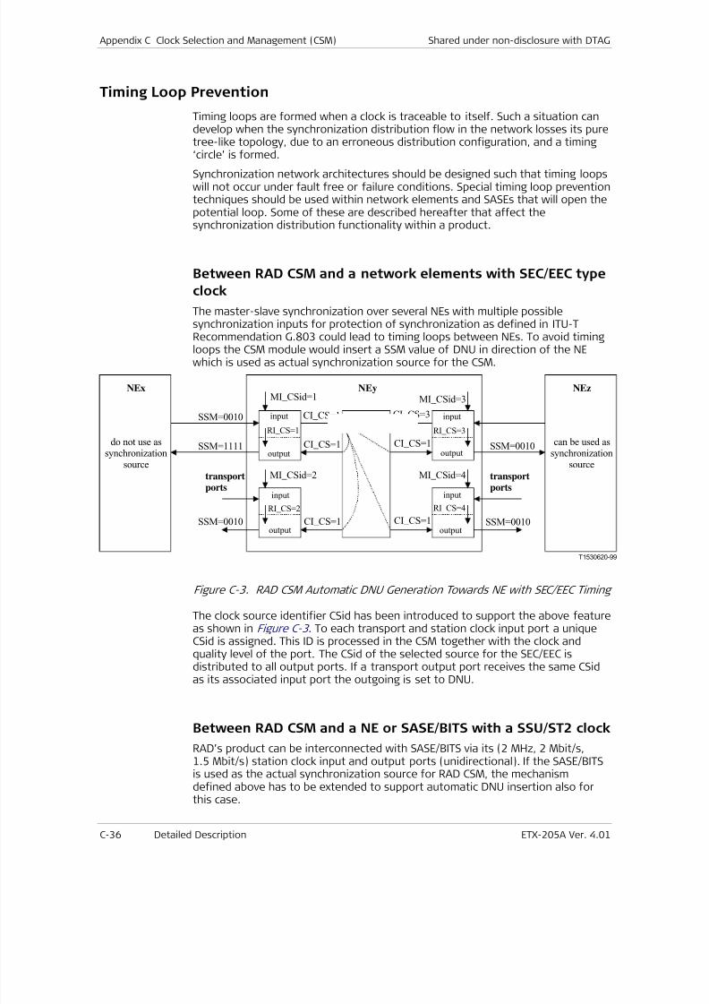
7/25/2019 Manual ETX-205A
http://slidepdf.com/reader/full/manual-etx-205a 392/409
Appendix C Clock Selection and Management (CSM) Shared under non-disclosure with DTAG
C-36 Detailed Description ETX-205A Ver. 4.01
Timing Loop Prevention
Timing loops are formed when a clock is traceable to itself. Such a situation candevelop when the synchronization distribution flow in the network losses its puretree-like topology, due to an erroneous distribution configuration, and a timing‘circle’ is formed.
Synchronization network architectures should be designed such that timing loopswill not occur under fault free or failure conditions. Special timing loop preventiontechniques should be used within network elements and SASEs that will open thepotential loop. Some of these are described hereafter that affect thesynchronization distribution functionality within a product.
Between RAD CSM and a network elements with SEC/EEC type
clock
The master-slave synchronization over several NEs with multiple possiblesynchronization inputs for protection of synchronization as defined in ITU-T
Recommendation G.803 could lead to timing loops between NEs. To avoid timingloops the CSM module would insert a SSM value of DNU in direction of the NEwhich is used as actual synchronization source for the CSM.
T1530620-99
RI_CS=1
MI_CSid=1
CI_CS=1
CI_CS=1
RI_CS=2
MI_CSid=2
RI_CS=3
MI_CSid=3
RI_CS=4
MI_CSid=4
SSM=0010
SSM=0010 SSM=0010
SSM=0010SSM=1111
CI_CS=1 CI_CS=1
CI_CS=3
CI_CS=1
input
output
input
output
input
output
input
output
do not use assynchronization
source
can be used assynchronization
source
transportports
transportports
NEyNEx NEz
Figure C-3. RAD CSM Automatic DNU Generation Towards NE with SEC/EEC Timing
The clock source identifier CSid has been introduced to support the above featureas shown in Figure C-3 . To each transport and station clock input port a uniqueCSid is assigned. This ID is processed in the CSM together with the clock andquality level of the port. The CSid of the selected source for the SEC/EEC is
distributed to all output ports. If a transport output port receives the same CSidas its associated input port the outgoing is set to DNU.
Between RAD CSM and a NE or SASE/BITS with a SSU/ST2 clock
RAD’s product can be interconnected with SASE/BITS via its (2 MHz, 2 Mbit/s,1.5 Mbit/s) station clock input and output ports (unidirectional). If the SASE/BITSis used as the actual synchronization source for RAD CSM, the mechanismdefined above has to be extended to support automatic DNU insertion also forthis case.
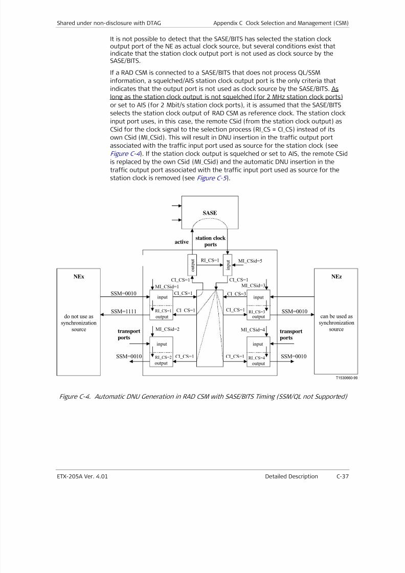
7/25/2019 Manual ETX-205A
http://slidepdf.com/reader/full/manual-etx-205a 393/409
Shared under non-disclosure with DTAG Appendix C Clock Selection and Management (CSM)
ETX-205A Ver. 4.01 Detailed Description C-37
It is not possible to detect that the SASE/BITS has selected the station clockoutput port of the NE as actual clock source, but several conditions exist thatindicate that the station clock output port is not used as clock source by theSASE/BITS.
If a RAD CSM is connected to a SASE/BITS that does not process QL/SSM
information, a squelched/AIS station clock output port is the only criteria that
indicates that the output port is not used as clock source by the SASE/BITS. As
long as the station clock output is not squelched (for 2 MHz station clock ports)or set to AIS (for 2 Mbit/s station clock ports), it is assumed that the SASE/BITS
selects the station clock output of RAD CSM as reference clock. The station clock
input port uses, in this case, the remote CSid (from the station clock output) as
CSid for the clock signal to the selection process (RI_CS = CI_CS) instead of its
own CSid (MI_CSid). This will result in DNU insertion in the traffic output port
associated with the traffic input port used as source for the station clock (see
Figure C-4 ). If the station clock output is squelched or set to AIS, the remote CSid
is replaced by the own CSid (MI_CSid) and the automatic DNU insertion in the
traffic output port associated with the traffic input port used as source for the
station clock is removed (see Figure C-5 ).
T1530660-99
MI_CSid=1CI_CS=1SSM=0010
SSM=0010 SSM=0010
SSM=0010SSM=1111
MI_CSid=2 MI_CSid=4
MI_CSid=3
MI_CSid=5
CI_CS=1
CI_CS=1 CI_CS=1
CI_CS=1
CI_CS=3
CI_CS=1CI_CS=1
RI_CS=1
RI_CS=1
RI_CS=2
RI_CS=3
RI_CS=4
output output
input
output
input
input
output
input
NEy
NEx NEz
o u t p u t
i n p u t
SASE
active
do not use assynchronization
source
can be used assynchronization
source
station clockports
transportports
transportports
Figure C-4. Automatic DNU Generation in RAD CSM with SASE/BITS Timing (SSM/QL not Supported)
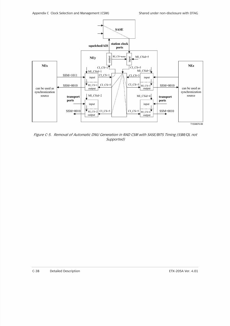
7/25/2019 Manual ETX-205A
http://slidepdf.com/reader/full/manual-etx-205a 394/409
Appendix C Clock Selection and Management (CSM) Shared under non-disclosure with DTAG
C-38 Detailed Description ETX-205A Ver. 4.01
T1530670-99
MI_CSid=1
CI_CS=1SSM=1011
SSM=0010 SSM=0010
SSM=0010SSM=0010
SASE
MI_CSid=2 MI_CSid=4
MI_CSid=3
MI_CSid=5
CI_CS=5
CI_CS=5 CI_CS=5
CI_CS=5
CI_CS=3
CI_CS=5CI_CS=1
RI_CS=1
RI_CS=2
RI_CS=3
RI_CS=4
RI_CS=none
output output
input
output
input
input
output
input
NEy
NEx NEz
o u t p u t
i n p u t
squelched/AIS
can be used assynchronization
source
can be used assynchronization
source
station clockports
transportports
transportports
Figure C-5. Removal of Automatic DNU Generation in RAD CSM with SASE/BITS Timing (SSM/QL not
Supported)
7/25/2019 Manual ETX-205A
http://slidepdf.com/reader/full/manual-etx-205a 395/409
Shared under non-disclosure with DTAG Appendix C Clock Selection and Management (CSM)
ETX-205A Ver. 4.01 Detailed Description C-39
Delay Times
The following delay times are respected by the CSM module:
1. Holdover message delay THM - This delay applies when the CSM (SEC/EEC)
switches to holdover because of loss of signal of the input reference and lack
of any other available reference. When this event occurs, the CSM (and
SEC/EEC) goes immediately into holdover but changes the output SSM to theholdover code after a delay which has been defined to be between 500 ms
and 2000 ms.
2. Non-switching message delay TNSM - This delay applies when the QL of the
selected synchronization source changes but no switchover to another source
is performed by the CSM. The outgoing SSM follows this change at the input
within a time defined to be less than 200 ms.
3. Switching message delay TSM - This delay applies when a new synchronization
source is selected by the CSM. The output SSM change, if any, is done after a
delay that has been defined to be between 180 ms and 500 ms.
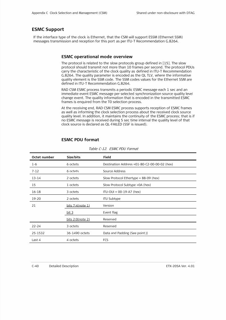
7/25/2019 Manual ETX-205A
http://slidepdf.com/reader/full/manual-etx-205a 396/409
Appendix C Clock Selection and Management (CSM) Shared under non-disclosure with DTAG
C-40 Detailed Description ETX-205A Ver. 4.01
ESMC Support
If the interface type of the clock is Ethernet, that the CSM will support ESSM (Ethernet SSM)messages transmission and reception for this port as per ITU-T Recommendation G.8264.
ESMC operational mode overview
The protocol is related to the slow protocols group defined in [15]. The slowprotocol should transmit not more than 10 frames per second. The protocol PDUscarry the characteristic of the clock quality as defined in ITU-T RecommendationG.8264. The quality parameter is encoded as the QL TLV, where the informativequality element is the SSM code. The SSM codes values for the Ethernet SSM aredefined in ITU-T Recommendation G.8264.
RAD CSM ESMC process transmits a periodic ESMC message each 1 sec and animmediate event ESMC message per selected synchronization source quality levelchange event. The quality information that is encoded in the transmitted ESMCframes is enquired from the T0 selection process.
At the receiving end, RAD CSM ESMC process supports reception of ESMC framesas well as informing the clock selection process about the received clock sourcequality level. In addition, it maintains the continuity of the ESMC process; that is ifno ESMC message is received during 5 sec time interval the quality level of thatclock source is declared as QL-FAILED (SSF is issued).
ESMC PDU format
Table C-12. ESMC PDU Format
Octet number Size/bits Field
1-6 6 octets Destination Address =01-80-C2-00-00-02 (hex)
7-12 6 octets Source Address
13-14 2 octets Slow Protocol Ethertype = 88-09 (hex)
15 1 octets Slow Protocol Subtype =0A (hex)
16-18 3 octets ITU-OUI = 00-19-A7 (hex)
19-20 2 octets ITU Subtype
21 bits 7:4(note 1) Version
bit 3 Event flag
bits 2:0(note 2) Reserved
22-24 3 octets Reserved
25-1532 36-1490 octets Data and Padding (See point J)
Last 4 4 octets FCS
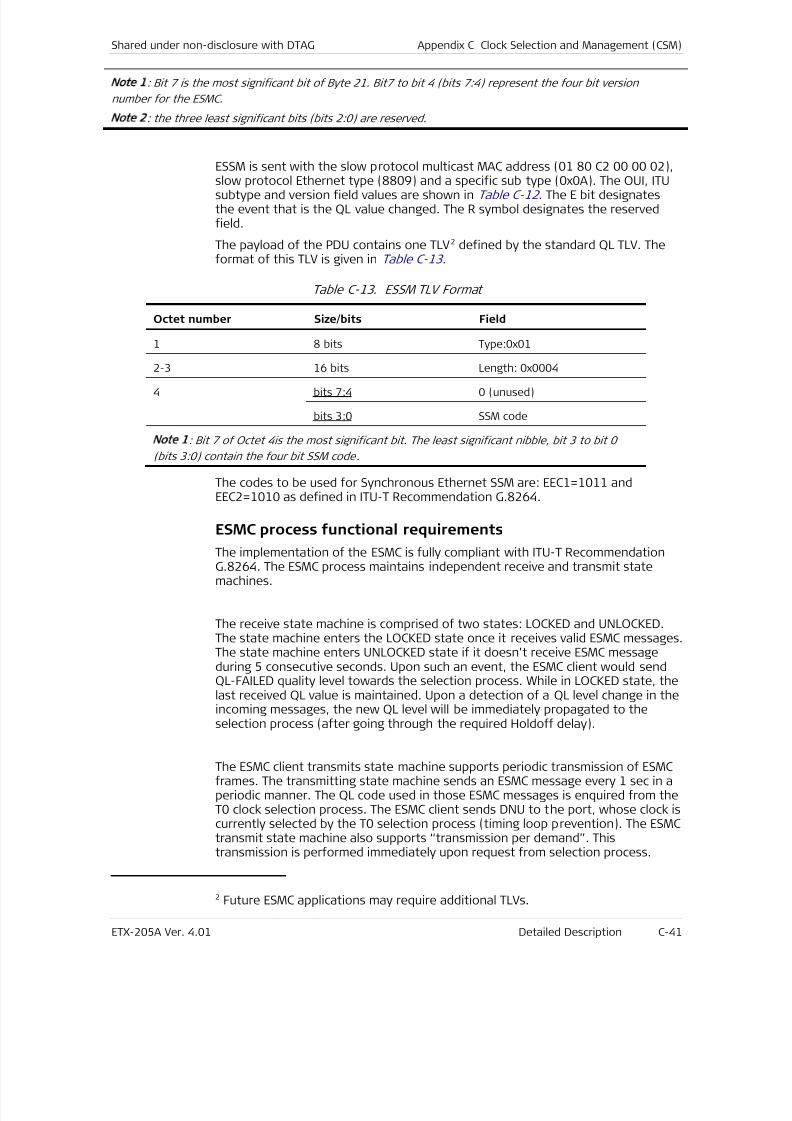
7/25/2019 Manual ETX-205A
http://slidepdf.com/reader/full/manual-etx-205a 397/409
Shared under non-disclosure with DTAG Appendix C Clock Selection and Management (CSM)
ETX-205A Ver. 4.01 Detailed Description C-41
Note 1
: Bit 7 is the most significant bit of Byte 21. Bit7 to bit 4 (bits 7:4) represent the four bit version
number for the ESMC.
Note 2
: the three least significant bits (bits 2:0) are reserved.
ESSM is sent with the slow protocol multicast MAC address (01 80 C2 00 00 02),
slow protocol Ethernet type (8809) and a specific sub type (0x0A). The OUI, ITUsubtype and version field values are shown in Table C-12 . The E bit designatesthe event that is the QL value changed. The R symbol designates the reservedfield.
The payload of the PDU contains one TLV2 defined by the standard QL TLV. Theformat of this TLV is given in Table C-13 .
Table C-13. ESSM TLV Format
Octet number Size/bits Field
1 8 bits Type:0x01
2-3 16 bits Length: 0x0004
4 bits 7:4 0 (unused)
bits 3:0 SSM code
Note 1
: Bit 7 of Octet 4is the most significant bit. The least significant nibble, bit 3 to bit 0
(bits 3:0) contain the four bit SSM code .
The codes to be used for Synchronous Ethernet SSM are: EEC1=1011 andEEC2=1010 as defined in ITU-T Recommendation G.8264.
ESMC process functional requirements
The implementation of the ESMC is fully compliant with ITU-T RecommendationG.8264. The ESMC process maintains independent receive and transmit statemachines.
The receive state machine is comprised of two states: LOCKED and UNLOCKED.The state machine enters the LOCKED state once it receives valid ESMC messages.The state machine enters UNLOCKED state if it doesn’t receive ESMC messageduring 5 consecutive seconds. Upon such an event, the ESMC client would sendQL-FAILED quality level towards the selection process. While in LOCKED state, thelast received QL value is maintained. Upon a detection of a QL level change in theincoming messages, the new QL level will be immediately propagated to theselection process (after going through the required Holdoff delay).
The ESMC client transmits state machine supports periodic transmission of ESMCframes. The transmitting state machine sends an ESMC message every 1 sec in aperiodic manner. The QL code used in those ESMC messages is enquired from theT0 clock selection process. The ESMC client sends DNU to the port, whose clock iscurrently selected by the T0 selection process (timing loop prevention). The ESMCtransmit state machine also supports “transmission per demand”. Thistransmission is performed immediately upon request from selection process.
2 Future ESMC applications may require additional TLVs.

7/25/2019 Manual ETX-205A
http://slidepdf.com/reader/full/manual-etx-205a 398/409
Appendix C Clock Selection and Management (CSM) Shared under non-disclosure with DTAG
C-42 Detailed Description ETX-205A Ver. 4.01
Such request may happen if the selection process selects a new referenceclocked with a different QL value (or alternatively its current selected sync sourcehas altered its quality level).
The transmission of ESMC frames on a specific port can be enabled/disabled byuser configuration. In QL-disbaled mode, ESMC frames are being transmitted onthe relevant ports (unless they have been disabled by the user) with QL value setto QL_DNU.
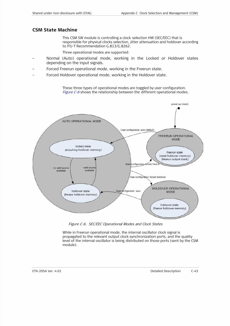
7/25/2019 Manual ETX-205A
http://slidepdf.com/reader/full/manual-etx-205a 399/409
Shared under non-disclosure with DTAG Appendix C Clock Selection and Management (CSM)
ETX-205A Ver. 4.01 Detailed Description C-43
CSM State Machine
This CSM SW module is controlling a clock selection HW (SEC/EEC) that isresponsible for physical clocks selection, jitter attenuation and holdover accordingto ITU-T Recommendation G.813/G.8262.
Three operational modes are supported:– Normal (Auto) operational mode, working in the Locked or Holdover states
depending on the input signals.
– Forced Freerun operational mode, working in the Freerun state.
– Forced Holdover operational mode, working in the Holdover state.
These three types of operational modes are toggled by user configuration.Figure C-6 shows the relationship between the different operational modes.
Figure C-6. SEC/EEC Operational Modes and Clock States
While in Freerun operational mode, the internal oscillator clock signal ispropagated to the relevant output clock synchronization ports, and the qualitylevel of the internal oscillator is being distributed on those ports (sent by the CSMmodule).
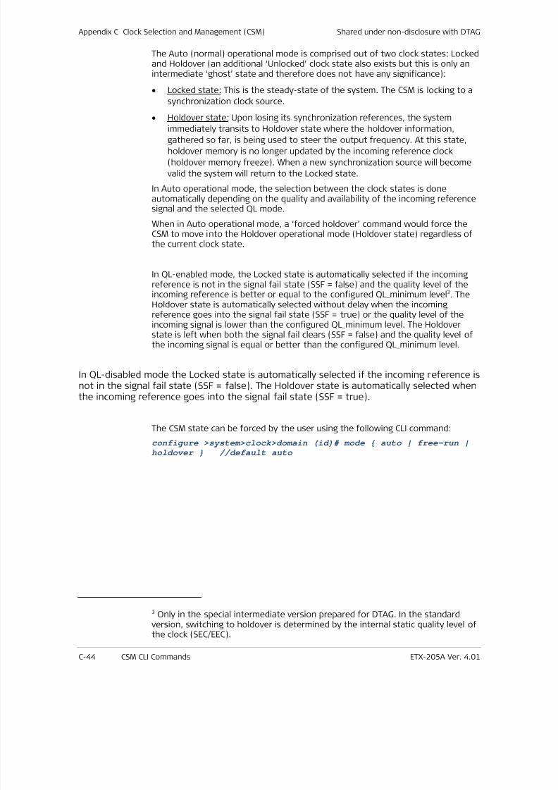
7/25/2019 Manual ETX-205A
http://slidepdf.com/reader/full/manual-etx-205a 400/409
Appendix C Clock Selection and Management (CSM) Shared under non-disclosure with DTAG
C-44 CSM CLI Commands ETX-205A Ver. 4.01
The Auto (normal) operational mode is comprised out of two clock states: Lockedand Holdover (an additional ‘Unlocked’ clock state also exists but this is only anintermediate ‘ghost’ state and therefore does not have any significance):
• Locked state: This is the steady-state of the system. The CSM is locking to a
synchronization clock source.
• Holdover state: Upon losing its synchronization references, the system
immediately transits to Holdover state where the holdover information,gathered so far, is being used to steer the output frequency. At this state,
holdover memory is no longer updated by the incoming reference clock
(holdover memory freeze). When a new synchronization source will become
valid the system will return to the Locked state.
In Auto operational mode, the selection between the clock states is doneautomatically depending on the quality and availability of the incoming referencesignal and the selected QL mode.
When in Auto operational mode, a ‘forced holdover’ command would force theCSM to move into the Holdover operational mode (Holdover state) regardless ofthe current clock state.
In QL-enabled mode, the Locked state is automatically selected if the incomingreference is not in the signal fail state (SSF = false) and the quality level of theincoming reference is better or equal to the configured QL_minimum level3. TheHoldover state is automatically selected without delay when the incomingreference goes into the signal fail state (SSF = true) or the quality level of theincoming signal is lower than the configured QL_minimum level. The Holdoverstate is left when both the signal fail clears (SSF = false) and the quality level ofthe incoming signal is equal or better than the configured QL_minimum level.
In QL-disabled mode the Locked state is automatically selected if the incoming reference isnot in the signal fail state (SSF = false). The Holdover state is automatically selected when
the incoming reference goes into the signal fail state (SSF = true).
The CSM state can be forced by the user using the following CLI command:
configure >system>clock>domain (id)# mode auto | free-run |holdover //default auto
3 Only in the special intermediate version prepared for DTAG. In the standardversion, switching to holdover is determined by the internal static quality level ofthe clock (SEC/EEC).
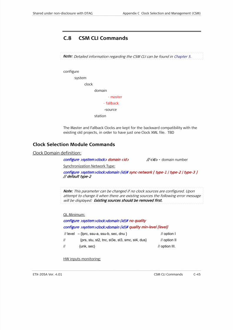
7/25/2019 Manual ETX-205A
http://slidepdf.com/reader/full/manual-etx-205a 401/409
Shared under non-disclosure with DTAG Appendix C Clock Selection and Management (CSM)
ETX-205A Ver. 4.01 CSM CLI Commands C-45
C.8 CSM CLI Commands
Note: Detailed information regarding the CSM CLI can be found in Chapter 5 .
configure
system
clock
domain
- master
- fallback
-source
station
The Master and Fallback Clocks are kept for the backward compatibility with the
existing old projects, in order to have just one Clock XML file. TBD
Clock Selection Module Commands
Clock Domain definition:
configure >system>clock> domain <id> //
<id> - domain number
Synchronization Network Type:
configure >system>clock>domain (id) sync-network type-1 | type-2 | type-3
// default type-2
Note: This parameter can be changed if no clock sources are configured. Upon
attempt to change it when there are existing sources the following error message
will be displayed: Existing sources should be removed first.
QL Minimum:
configure >system>clock>domain (id) no quality
configure >system>clock>domain (id) quality min-level level
// level – lprc, ssu-a, ssu-b, sec, dnu // option I
// prs, stu, st2, tnc, st3e, st3, smc, st4, dus // option II
// unk, sec // option III.
HW inputs monitoring:
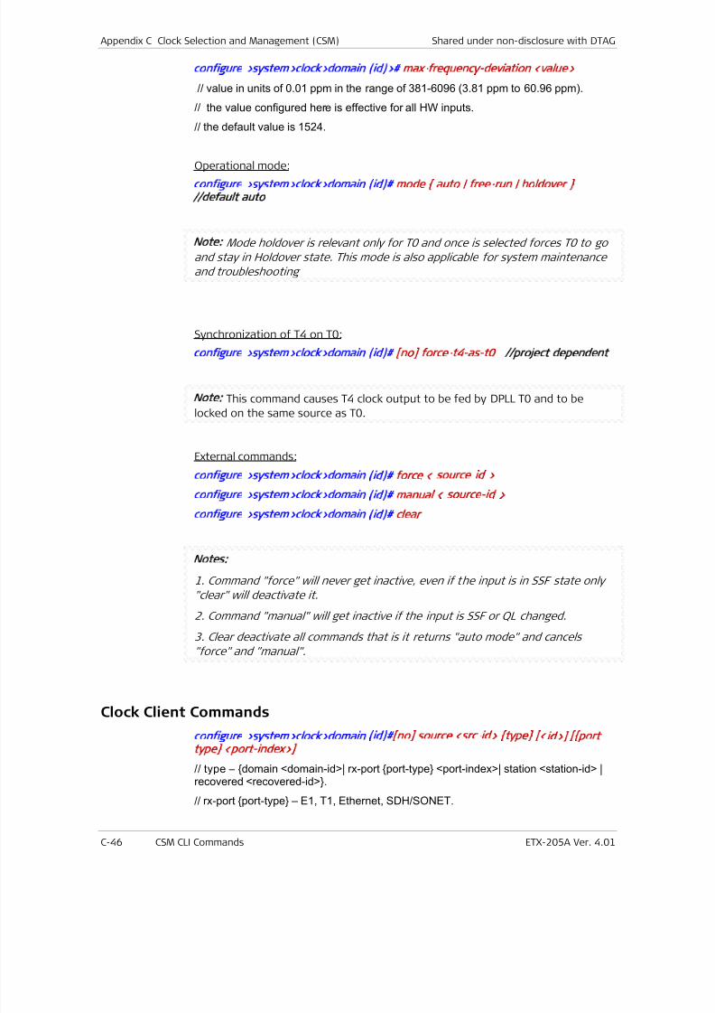
7/25/2019 Manual ETX-205A
http://slidepdf.com/reader/full/manual-etx-205a 402/409
Appendix C Clock Selection and Management (CSM) Shared under non-disclosure with DTAG
C-46 CSM CLI Commands ETX-205A Ver. 4.01
configure >system>clock>domain (id)> max-frequency-deviation <value>
// value in units of 0.01 ppm in the range of 381-6096 (3.81 ppm to 60.96 ppm).
// the value configured here is effective for all HW inputs.
// the default value is 1524.
Operational mode:configure >system>clock>domain (id) mode auto | free-run | holdover
//default auto
Note: Mode holdover is relevant only for T0 and once is selected forces T0 to go
and stay in Holdover state. This mode is also applicable for system maintenance
and troubleshooting
Synchronization of T4 on T0:configure >system>clock>domain (id) [no] force-t4-as-t0 //project dependent
Note: This command causes T4 clock output to be fed by DPLL T0 and to be
locked on the same source as T0.
External commands:
configure >system>clock>domain (id) force < source-id >
configure >system>clock>domain (id) manua l < source-id >
configure >system>clock>domain (id) clear
Notes:
1. Command "force" will never get inactive, even if the input is in SSF state only
"clear" will deactivate it.
2. Command "manual" will get inactive if the input is SSF or QL changed.
3. Clear deactivate all commands that is it returns "auto mode" and cancels
"force" and "manual".
Clock Client Commands
configure >system>clock>domain (id) [no] source <src-id> type [<id>] [port
type <po rt-index>]
// type – domain <domain-id>| rx-port port-type <port-index>| station <station-id> |recovered <recovered-id>.
// rx-port port-type – E1, T1, Ethernet, SDH/SONET.
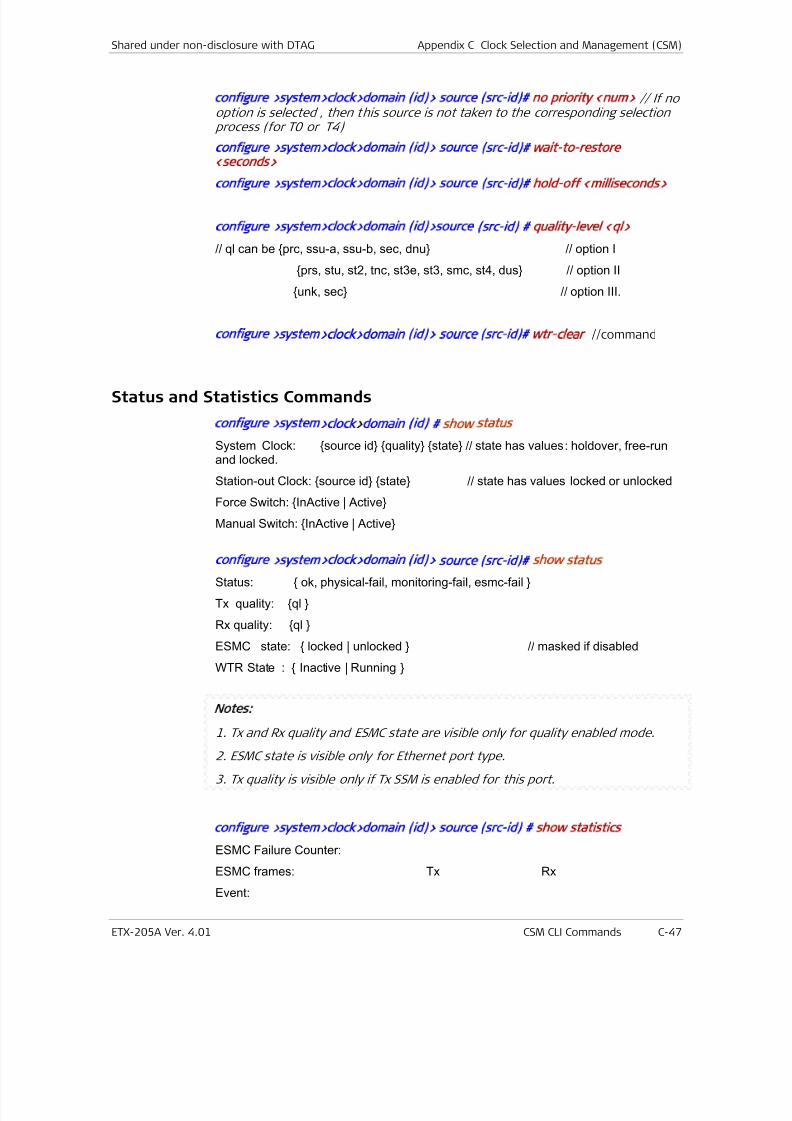
7/25/2019 Manual ETX-205A
http://slidepdf.com/reader/full/manual-etx-205a 403/409
Shared under non-disclosure with DTAG Appendix C Clock Selection and Management (CSM)
ETX-205A Ver. 4.01 CSM CLI Commands C-47
configure >system>clock>domain (id)> source (src-id) no priority <num> // If nooption is selected , then this source is not taken to the corresponding selectionprocess (for T0 or T4)
configure >system>clock>domain (id)> source (src-id) wait-to-restore
<seconds>
configure >system>clock>domain (id)> source (src-id) hold-off <m illiseconds>
configure >system>clock>domain (id)>source (src-id) quality-level <ql>
// ql can be prc, ssu-a, ssu-b, sec, dnu // option I
prs, stu, st2, tnc, st3e, st3, smc, st4, dus // option II
unk, sec // option III.
configure >system>clock>domain (id)> source (src-id) wtr-clear //command
Status and Statistics Commands
configure >system>clock>domain (id) show status
System Clock: source id quality state // state has values: holdover, free-run and locked.
Station-out Clock: source id state // state has values locked or unlocked
Force Switch: InActive | Active
Manual Switch: InActive | Active
configure >system>clock>domain (id)> source (src-id) show status
Status: ok, physical-fail, monitoring-fail, esmc-fail
Tx quality: ql
Rx quality: ql
ESMC state: locked | unlocked // masked if disabled
WTR State : Inactive | Running
Notes:
1. Tx and Rx quality and ESMC state are visible only for quality enabled mode.
2. ESMC state is visible only for Ethernet port type.
3. Tx quality is visible only if Tx SSM is enabled for this port.
configure >system>clock>domain (id)> source (src-id) show statistics
ESMC Failure Counter:
ESMC frames: Tx Rx
Event:

7/25/2019 Manual ETX-205A
http://slidepdf.com/reader/full/manual-etx-205a 404/409
Appendix C Clock Selection and Management (CSM) Shared under non-disclosure with DTAG
C-48 CSM CLI Commands ETX-205A Ver. 4.01
Information:
configure >system>clock>domain (id)> source (src-id) clear statistics

7/25/2019 Manual ETX-205A
http://slidepdf.com/reader/full/manual-etx-205a 405/409
Publication No. SUP-220-09/11 The Access Company
Terminal Block
Connectorfor DC Power Supply Connection
Supplement
5
Ignore this supplement if the unit is AC-powered.
Certain DC-powered units are equippedwith a plastic 3-pin VDC-IN power input
connector, located on the unit rear
panel. Different variations of the
connector are shown in 0F igure 1. All
are functionally identical.
Supplied with such units is a kit
including a mating Terminal Block (TB)
type connector plug for attaching to
your power supply cable.
Connect the wires of your power
supply cable to the TB plug, according
to the voltage polarity and assembly
instructions provided on the following
pages. Figure 1. TB DC Input Connector Types
Appearing on Unit Panels
Prepare all connections to the TB plug before inserting it into the unit’s VDC-IN
connector.
Caution
Note
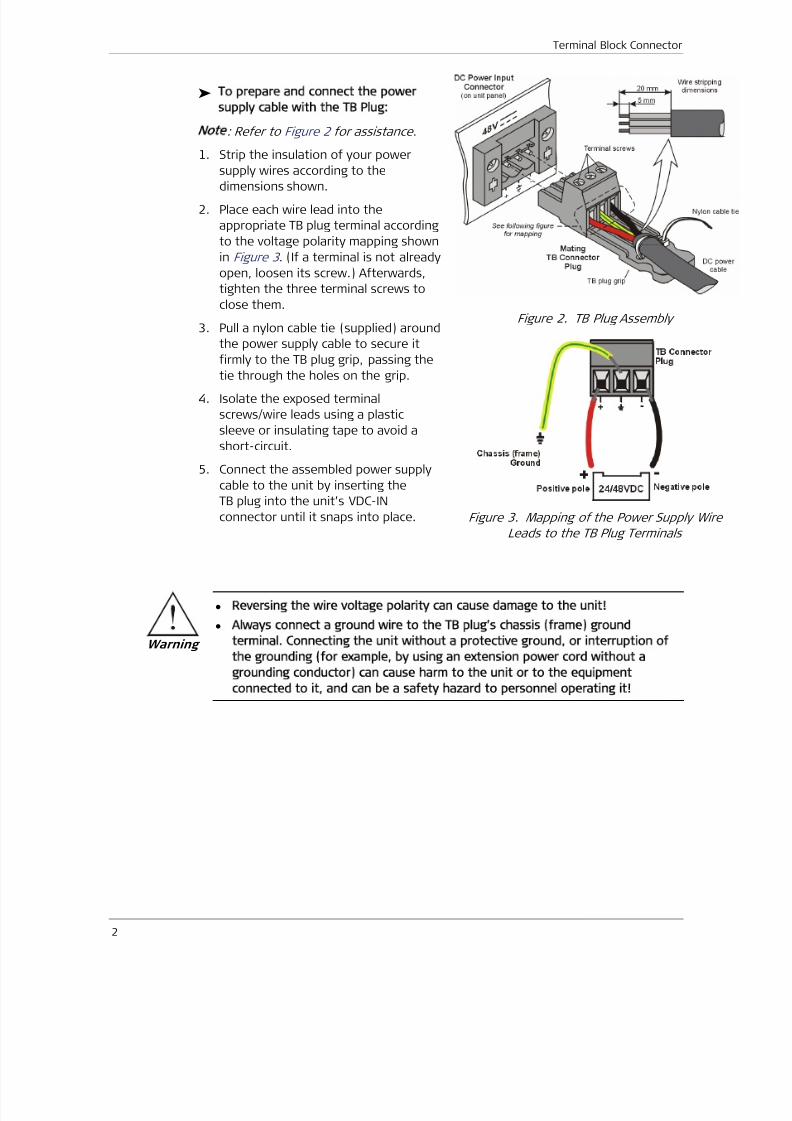
7/25/2019 Manual ETX-205A
http://slidepdf.com/reader/full/manual-etx-205a 406/409
Terminal Block Connector
2
To prepare and connect the power
supply cable with the TB Plug:
ot : Refer to 1Figure 2 for assistance .
1. Strip the insulation of your power
supply wires according to the
dimensions shown.
2. Place each wire lead into the
appropriate TB plug terminal according
to the voltage polarity mapping shown
in 2Figure 3 . (If a terminal is not already
open, loosen its screw.) Afterwards,
tighten the three terminal screws to
close them.
3. Pull a nylon cable tie (supplied) around
the power supply cable to secure it
firmly to the TB plug grip, passing the
tie through the holes on the grip.
4. Isolate the exposed terminal
screws/wire leads using a plastic
sleeve or insulating tape to avoid a
short-circuit.
5. Connect the assembled power supply
cable to the unit by inserting the
TB plug into the unit’s VDC-IN
connector until it snaps into place.
Figure 2. TB Plug Assembly
Figure 3. Mapping of the Power Supply Wire
Leads to the TB Plug Terminals
• Reversing the wire voltage polarity can cause damage to the unit
• Always connect a ground wire to the TB plug’s chassis (frame) ground
terminal. Connecting the unit without a protective ground, or interruption of
the grounding (for example, by using an extension power cord without a
grounding conductor) can cause harm to the unit or to the equipment
connected to it, and can be a safety hazard to personnel operating it
Warning
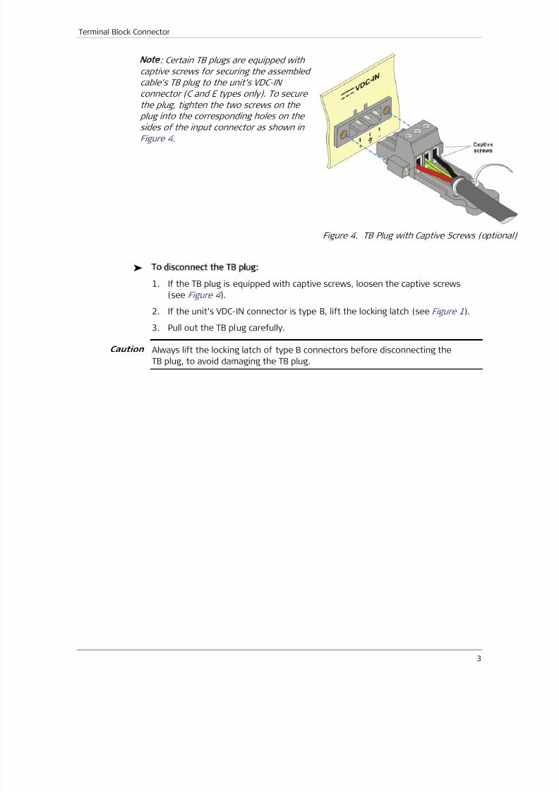
7/25/2019 Manual ETX-205A
http://slidepdf.com/reader/full/manual-etx-205a 407/409
Terminal Block Connector
3
ot : Certain TB plugs are equipped with
captive screws for securing the assembled
cable’s TB plug to the unit’s VDC-IN
connector (C and E types only). To secure
the plug, tighten the two screws on the
plug into the corresponding holes on the
sides of the input connector as shown in3F igure 4 .
Figure 4. TB Plug with Captive Screws (optiona
To disconnect the TB plug:
1. If the TB plug is equipped with captive screws, loosen the captive screws
(see 4Figure 4 ).
2. If the unit’s VDC-IN connector is type B, lift the locking latch (see 5Figure 1).
3. Pull out the TB plug carefully.
Always lift the locking latch of type B connectors before disconnecting the
TB plug, to avoid damaging the TB plug.
Caution

7/25/2019 Manual ETX-205A
http://slidepdf.com/reader/full/manual-etx-205a 408/409
Terminal Block Connector
4

7/25/2019 Manual ETX-205A
http://slidepdf.com/reader/full/manual-etx-205a 409/409