manual - dcbnet.com · default ip address is 192.168.0.96, port number 8000 rather than port 23....
TRANSCRIPT

8500117
EST 9600
TABLE OF CONTENTS
SECTION 1 - OVERVIEW ............................................................................2
SECTION 2 - SPECIFICATIONS .................................................................5
SECTION 3 - CONTROLS AND INDICATORS...........................................6
SECTION 4 - INSTALLATION.....................................................................7
SECTION 5 – QUICK SETUP GUIDE .........................................................8
SECTION 6 - SETUP.................................................................................. 11
SECTION 7 - INTERFACE SIGNALS AND CABLING.............................. 22
SECTION 8 - TROUBLESHOOTING ........................................................ 26
SECTION 9 - WARRANTY......................................................................... 27
Data Comm for Business, Inc.PO Box 6329Champaign, IL 61826-6329 December 1, 2006(217) 897-6600 Firmware Version: 1.03www.dcbnet.com

2
1. OVERVIEW
DESCRIPTION
The EST-9600 is a serial server that allows multi-drop devices to use Ethernet LANs eitherunencrypted or with 128-bit AES encryption. The EST-9600 connects any HDLC based synchronousprotocol serial device through a LAN and between LANs via routers. The EST-9600 is designedspecifically to support synchronous polling protocols that are HDLC based. These protocols includeSDLC, BDLC, X.25, Frame Relay, synchronous PPP protocol, etc. These protocols are often errorcorrected, and the EST-9600 allows these protocols to work through routed local and wide areanetworks. The EST-9600 uses UDP protocol to deliver the HDLC traffic, allowing the necessarydata connection over a local LAN and across routed networks. The EST-9600 functionsindependently of the device protocol, allowing HDLC protocols to be carried with no configurationchanges.
An EST-9600 host authenticates with remote drop EST-9600s to allow serial synchronous HDLCdata connections. Remote drop EST-9600s can authenticate with both a primary host and a backuphost. This feature makes it easy to have redundant host sites that will always receive the same pollresponses as the master host site. If the objective is to have a backup host site or have a second sitethat always monitors the RTU responses, the EST-9600 makes it simple and easy to accomplish.
The EST-9600 supports RS-232 serial interface speeds up to 230 Kbps, RS-530 speeds up to 2048Kbps.
To deliver HDLC traffic via Ethernet in as close to the nature of HDLC as possible, the EST-9600uses TCP/UDP “best-effort”, speedy delivery, rather than the delay and extra overhead that TCP/IPerror-correction and flow control could cause. Up to 20 drop EST-9600s may be used with each hostEST-9600.
The EST-9600 can be managed through its serial port, via telnet, or with a web browser. Remoteconfiguration is supported using TCP/IP (telnet) or any web browser. Security features of the EST-9600 include fine-grained configuration and management controls as well as the ability to turn offremote management functions.
Instead of replacing your existing host computers and terminals to migrate to Ethernet, add theEST-9600 for a fraction of the cost. OEM manufacturers can design the EST-9600 into theirproducts or use it as an add-on method to gain Ethernet connectivity.
FEATURES
• Industrial rated -40° to +70° C• Ethernet port: 10/100BaseT• Encapsulates HDLC protocols over Ethernet networks• Point-to-point or point-to-multi-point for serial synchronous polling applications• AES 128-bit encrypted or non-encrypted payload• UDP transport for non-interference with HDLC error correction functions• Synchronous serial RS232 port• Option for RS530/V.35 port• Internal or external sync clock• Speeds to 2.048 Mbps• Supports up to 20 Drops• Backup host option

3
• Easy to setup and maintain• Web browser, telnet or serial port configuration• Statistics, logging and diagnostic tools• Can authenticate with RADIUS server• Stand-alone or Rack Mounting• 120, 220 VAC, 12, 24, 48 and 125 VDC options
EST 9600 Front View
EST 9600 Rear View (48 VDC Version)

4
APPLICATION

5
2. SPECIFICATIONS
PORTS
One synchronous serial port:RS-232 (per EIA/TIA 561 RJ 45 connector)
Speeds to 230 KbpsRS-530 or V.35 balanced interface option
Speeds to 2.048 MbpsOne 10/100BaseT Ethernet portOne asynchronous 9600 baud RS-232 port for setup
HDLC COMPATIBILITY
Accepts/Sends any HDLC frame up to 1500 bytes longData Encoded via NRZ or NRZIStandard CRC-CCITT as used in HDLC or Sync PPPInternal or External clocksIncluding but not limited to: HDLC, Sync PPP, Frame relay
PROTOCOL FEATURES
IP, DHCP (Client), UDP, ICMP, HTTP, TCP/IPAuthentication: internal name/password database, or up to two external, customer-supplied
RADIUS serversEncryption: 128-bit AES or NONEOnce connection is established, tunnels use UDP to deliver packetsWeb browser, telnet, or serial port configuration and managementDefault IP address: 192.168.0.96
INDICATORS
Front - Power, Status, Valid received sync data, port activityRear – LAN connection, LAN activity
CONTROLS
DIP switch:Setup (initial setup using serial terminal)Reset
PHYSICAL/ELECTRICAL
Power: 6VDC external supply, 1330 ma standard12, 24, 48, 125 VDC and 240 VAC options are availableSupplied with 120 VAC external power supply5 ¼”x 5 ½”x 1 ¾”One pound
ENVIRONMENTAL
Operational Temperature: −40° to +70° CStorage Temperature: −50° to +75° CHumidity: < 95% Non-condensing

6
3. CONTROLS AND INDICATORS
CONTROLS
DIP Switches
Switch Down Up
1 Normal Reset2 Setup Port Inactive Setup Port Active3 Must be Down4 Must be Down
INDICATORS
Front
Indicator Condition Meaning
Power ON Power to unitStatus OFF
ONSet for Internal ClockSet for External Clock
Sync Flashing Sync Port Data ActivitySetup Flashing Setup Port Data Activity
Rear
Indicator Condition Meaning
Top Flashing LAN activity presentBottom ON Good LAN connection

7
4. INSTALLATION
UNPACKING
The following is included with each unit:
• Unit and external power supply• Cable for initial setup using a PC• Manual• Information regarding warranty, maintenance contracts and repair
SETUP
Initial setup is done through the SETUP port using the serial cable provided. See Section 6 forspecific information.
SECURITY
Link Security
The EST-9600 tunnels HDLC serial protocols encrypted or non-encrypted. The EST-9600default is encryption enabled. For private networks that are already considered to besufficiently secure, turning encryption off may be an acceptable mode of operation.
The EST-9600 has default pass phrases. If encryption is turned on, be aware that the passphrases should be changed from the default values.
Management Security
The EST-9600 can be managed via the Serial Setup port, via Telnet, or via a Web Browser. Theserial port can be enabled or disabled using switch 2 on the rear of the unit. Switch 2 must beup for the serial management port to be active.
The encrypted HDLC data is sent via the ethernet interface. This is the same interface used toaccess telnet or browser management. The telnet port can be enabled or disabled. The telnetport is a non-standard port 8000. This provides some degree of security, as the default port fortelnet is port 23.
Management using the browser port can also be enabled or disabled. In addition, the browserport can be limited to only 1 or 2 specific IP addresses.
CONNECTIONS
Connect the synchronous port to the equipment using an appropriate cable. See Section 6 forpinouts and cabling guidance.
Connect the Ethernet port to the local area network using standard ethernet cables. A straightthrough patch cord is used for connection to a hub or switch. To other equipment, a crossover cablemay be required.

8
5. QUICK SETUP GUIDE
For serial or telnet quick setup, the default user NAME is “admin”. The default PASSWORD isblank, so enter nothing at the prompt. Just press the “Enter” key to continue. If using telnet, thedefault IP address is 192.168.0.96, port number 8000 rather than port 23. For serial connections,use 9600 bps, 8 data bits, no parity, no flow control. For a quick setup, select the following 4highlighted menu items. The menus are shown in detail below:
2 Set HDLC Tunnel Values3 Set Ethernet LAN Values4 Set HDLC Port Values8 Save and Activate
The EST-9600 can tunnel in encrypted mode or with no encryption. Menu selection 2 is used if youwish to change from the default of Encryption ON to NONE. For Tunnel Mode, menu selection 3,set the Tunnel Mode to either Host or Drop. Drop is the default since most units will be drops inmulti-drop applications. When configuring drops, select “5. Primary Host Values”.
At drops it is necessary to enter the IP address of the host by selecting “5. Primary Host Values”.Drops “find” the host via the IP address. At the Host unit no address is entered for the drops. TheHost discovers the address of the drop from the drop’s connection request to the host. Menuselection 5 gives you the menu below where the Primary Host Values are entered.

9
The address of the host is entered per the following example:->: 1 192.168.10.10
In the “LAN Values” menu, enter the IP Address, the Subnet Mask and the Default Gateway for theunit. This is required in both the Host and the Drop units.
In the “HDLC Port Values” menu, enter the clock choice for the drops and the host. The default isInternal Clock. There are jumpers inside the EST-9600 that must be set to match the softwaresetting. See the photos below for details on changing the clock source jumpers.
The internal jumpers are accessed by removing the 2Phillips head screws that hold on the front panel. Removethe 2 screws and slide the circuit board forward to exposethe jumpers. There are 2 sets of jumpers. The longer setof jumpers nearest the front panel set the HDLC serialinterface to RS232 when toward the front panel orRS422/RS485/RS530 when set away from the front. Thesmaller set of jumpers about an inch further back set theclock source to internal when set toward the front andexternal clock when set toward the rear.
Defaults are RS232 electrical interface and internal clocksource.

10
When setting the EST-9600 to Internal Clock source, also set the rate. The Encoding, menuselection 3, defaults to NRZ (non-return to zero). This is typical for PPP, Frame Relay, X.25 data.NRZI is often used with IBM SDLC protocols.
After making all the necessary changes, select item 8 from the main menu, “ Save and Activate”.Remember that after changing the IP address, if the EST-9600 is again accessed for setup via telnetor a web browser, it is necessary to change the address of the PC to match the IP subnet of the EST-9600.

11
6. SETUP
INTRODUCTION
Initial setup is performed using a PC with terminal emulation software (HyperTerm). After initialconfiguration is complete, Telnet or a Web Browser may be used for further configuration and formonitoring.
CONNECTIONS
Using the serial cable provided, connect the PC to the SETUP port on EST. Put DIP switch 2 inthe UP position. The SETUP port will remain active as long as switch 2 is in the UP position.
USING A PC
Set the PC terminal emulation software as follows:
Rate: 9600Data Bits: 8Stop Bits: 1Parity: NoneFlow Control: None (disabled)
Apply power to the EST.
USING THE SETUP PORT
After the unit boots, press <Enter>. An Enter name: prompt should appear. Enter the user nameadmin. At the Enter password: prompt, press <Enter>. The following menu should appear.
Enter name: adminEnter password:
---- Welcome to the EST-9600 version v1_00 Setup Program ----
1 Set Administration Values 2 Set HDLC Tunnel Values 3 Set Ethernet LAN Values 4 Set HDLC Port Values 5 Display Settings 6 Display Status 7 Reset Default Settings or Reset Unit 8 Save and Activate 9 Exit without Saving
Select a function by number ->:
12
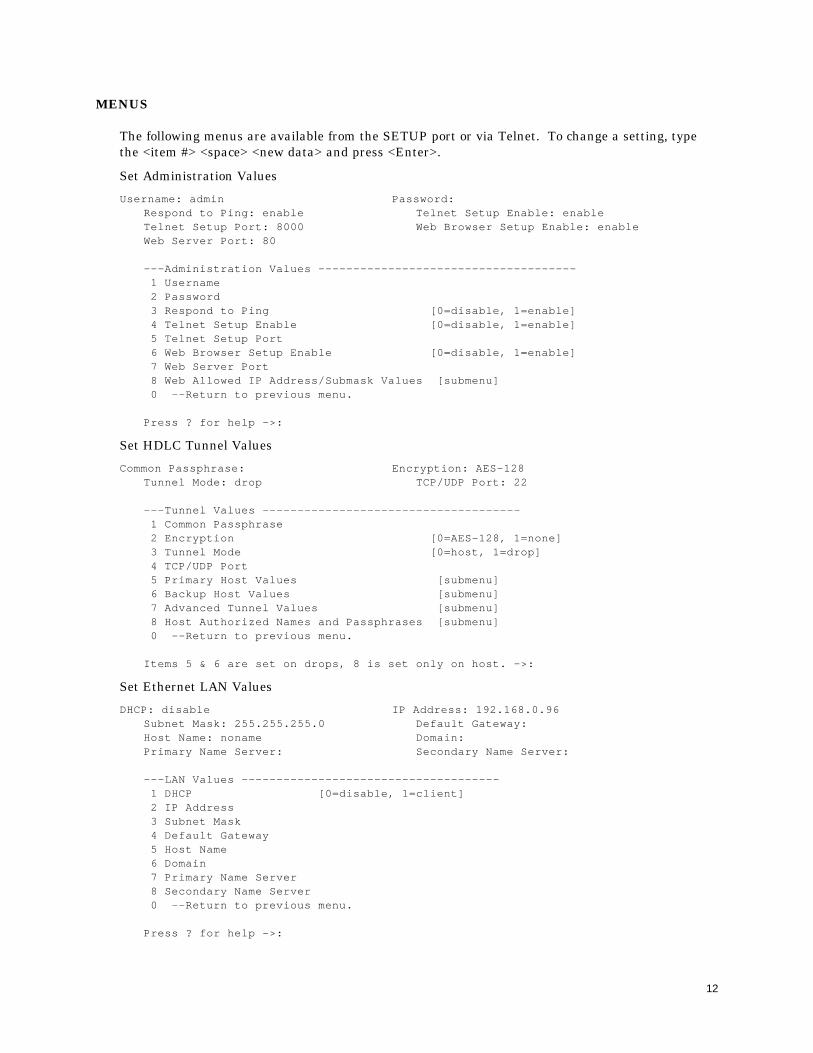
MENUS
The following menus are available from the SETUP port or via Telnet. To change a setting, typethe <item #> <space> <new data> and press <Enter>.
Set Administration Values
Username: admin Password:Respond to Ping: enable Telnet Setup Enable: enableTelnet Setup Port: 8000 Web Browser Setup Enable: enableWeb Server Port: 80
---Administration Values ------------------------------------- 1 Username 2 Password 3 Respond to Ping [0=disable, 1=enable] 4 Telnet Setup Enable [0=disable, 1=enable] 5 Telnet Setup Port 6 Web Browser Setup Enable [0=disable, 1=enable] 7 Web Server Port 8 Web Allowed IP Address/Submask Values [submenu] 0 --Return to previous menu.
Press ? for help ->:
Set HDLC Tunnel Values
Common Passphrase: Encryption: AES-128Tunnel Mode: drop TCP/UDP Port: 22
---Tunnel Values ------------------------------------- 1 Common Passphrase 2 Encryption [0=AES-128, 1=none] 3 Tunnel Mode [0=host, 1=drop] 4 TCP/UDP Port 5 Primary Host Values [submenu] 6 Backup Host Values [submenu] 7 Advanced Tunnel Values [submenu] 8 Host Authorized Names and Passphrases [submenu] 0 --Return to previous menu.
Items 5 & 6 are set on drops, 8 is set only on host. ->:
Set Ethernet LAN Values
DHCP: disable IP Address: 192.168.0.96Subnet Mask: 255.255.255.0 Default Gateway:Host Name: noname Domain:Primary Name Server: Secondary Name Server:
---LAN Values ------------------------------------- 1 DHCP [0=disable, 1=client] 2 IP Address 3 Subnet Mask 4 Default Gateway 5 Host Name 6 Domain 7 Primary Name Server 8 Secondary Name Server 0 --Return to previous menu.
Press ? for help ->:

13
Set HDLC Port Values
Sync Mode Clock Source: internal Internal Clock Rate (bps): 56000Encoding: nrz Max Transmit Unit (bytes): 1500
---HDLC Values ------------------------------------- 1 Sync Mode Clock Source [0=external, 1=internal] 2 Internal Clock Rate (bps) [0=1200, 1=2400, 2=4800, 3=9600, 4=19200, 5=38400, 6=56000, 7=64000, 8=128000, 9=192000, 10=256000, 11=512000, 12=768000, 13=1536000, 14=2048000] 3 Encoding [0=nrz, 1=nrzi] 4 Max Transmit Unit (bytes) 0 --Return to previous menu.
Press ? for help ->:
Display Settings-----------------------------------------------
== Administration Values ==Username: admin Password:Respond to Ping: enable Telnet Setup Enable: enableTelnet Setup Port: 8000 Web Browser Setup Enable: enableWeb Server Port: 80-----------------------------------------------== Web Allowed IP Address/Netmask Values ==Allowed Web IP Address 1: Allowed Web IP Netmask 1:Allowed Web IP Address 2: Allowed Web IP Netmask 2:-----------------------------------------------== Tunnel Values ==Common Passphrase: Encryption: AES-128Tunnel Mode: drop TCP/UDP Port: 22-----------------------------------------------== Primary Host Values ==Primary IP Address: 192.168.0.97 Primary Passname: client1Primary Passphrase: ***press return for more, ESC to quit:-----------------------------------------------== Backup Host Values ==Backup IP Address: Backup Passname: client1Backup Passphrase: ***-----------------------------------------------== Host Authorized Names and Passphrases - ==Drop 1: client1 Passphrase 1: ***Drop 2: Passphrase 2:Drop 3: Passphrase 3:Drop 4: Passphrase 4:Drop 5: Passphrase 5:-----------------------------------------------== Host Authorized Names and Passphrases - ==Drop 6: Passphrase 6:Drop 7: Passphrase 7:Drop 8: Passphrase 8:Drop 9: Passphrase 9:Drop 10: Passphrase 10:press return for more, ESC to quit:-----------------------------------------------== Host Authorized Names and Passphrases - ==Drop 11: Passphrase 11:Drop 12: Passphrase 12:Drop 13: Passphrase 13:Drop 14: Passphrase 14:Drop 15: Passphrase 15:

14
-----------------------------------------------== Host Authorized Names and Passphrases - ==Drop 16: Passphrase 16:Drop 17: Passphrase 17:Drop 18: Passphrase 18:Drop 19: Passphrase 19:Drop 20: Passphrase 20:-----------------------------------------------== Advanced Tunnel Values ==Host Authentication Mode: user-list Idle Disconnect Time (seconds): 120Send Keep-Alives Time (seconds): 40press return for more, ESC to quit:-----------------------------------------------== RADIUS Server 1 Values ==RADIUS Server 1 Name/Addr: RADIUS Server 1 UDP Port: 1812RADIUS Server 1 NAS Index: 0 RADIUS Server 1 Shared Secret:-----------------------------------------------== RADIUS Server 2 Values ==RADIUS Server 2 Name/Addr: RADIUS Server 2 UDP Port: 1812RADIUS Server 2 NAS Index: 0 RADIUS Server 2 Shared Secret:-----------------------------------------------== RADIUS Common Values ==RADIUS Server timeout (seconds): 2 RADIUS Server retries: 2-----------------------------------------------== LAN Values ==DHCP: disable IP Address: 192.168.0.96Subnet Mask: 255.255.255.0 Default Gateway:Host Name: noname Domain:Primary Name Server: Secondary Name Server:press return for more, ESC to quit:-----------------------------------------------== HDLC Values ==Sync Mode Clock Source: internal Internal Clock Rate (bps): 56000Encoding: nrz Max Transmit Unit (bytes): 1500
Display Status
=== Ethernet Status ===HWaddr 00:06:3B:00:51:C9addr:192.168.0.96 Bcast:192.168.0.255 Mask:255.255.255.0UP BROADCAST RUNNING MULTICAST MTU:1500 Metric:1RX packets:0 errors:0 dropped:0 overruns:0 frame:0TX packets:0 errors:525 dropped:0 overruns:0 carrier:525collisions:0 txqueuelen:1000
=== HDLC Status ===UP POINTOPOINT NOARP MTU:1500 Metric:1RX packets:0 errors:0 overruns:0 frame:0TX packets:0 errors:0 dropped:0 overruns:0 carrier:2collisions:0 txqueuelen:10
=== Tunnel node Status ===Location Rx Count Tx Count Tx Drops Connects UserName--------------------- ---------- ---------- ---------- ---------- --------HDLC 0 0 0 1 none192.168.0.97:22 0 0 0 0 client1
(Counts are counts of packets, not bytes.)
Display tunnel log file (y,n,p):

15
Reset Default Settings or Reset Unit
To reset to default values, Press D.To reset Unit, press R.Press return to exit :
Save and Activate
Setup complete.No changes to activate.Bye
USING A WEB BROWSER
Below is the main web browser menu. The left side shows the main menu selections. The righthand column shows the sub menus for the main menu selections that have sub menus. All pageswith fields that can filled in have help screens that describe the function of that selection. On theURL bar of the browser, enter the IP address of the EST-9600. If you have changed the default webbrowser port from 80, enter the new port number with the IP address, i.e. “192.168.0.96:7999”

16
ADMINISTRATION
Admin Password. Access to the EST-9600 is controlled with the Administration functions. UnderAdministration the user name and password are set.
Admin Access Control. Ping can be enabled or disabled. Telnet access can be enabled or disabled.The Telnet setup port can be changed from the default 8000 to any other port. Web browser accesscan be enabled or disabled. The web browser port can be changed from the default 80 to any otherport. Access can be limited to a list of 2 IP addresses.

17
Set Clock sets a relative clock, relative to the power-on time of the EST-9600. The clock is resetwhen the EST-9600 is rebooted.
Set All Defaults puts all the settings back to the factory default state.
Config File is a way to save the configuration file to a PC or to load a working configuration file froma PC into the EST-9600.
Firmware Upgrade is used to upgrade EST-9600 firmware.
System Reboot reboots the EST-9600.
Version Info reports the firmware version.
18
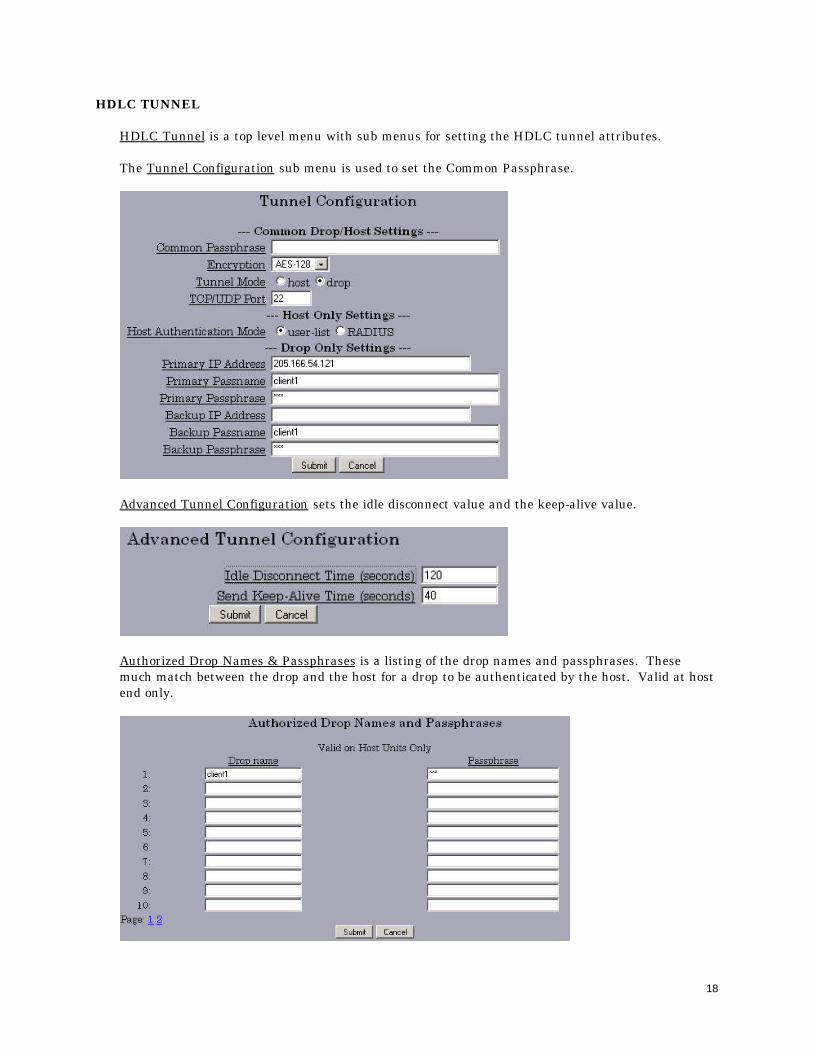
HDLC TUNNEL
HDLC Tunnel is a top level menu with sub menus for setting the HDLC tunnel attributes.
The Tunnel Configuration sub menu is used to set the Common Passphrase.
Advanced Tunnel Configuration sets the idle disconnect value and the keep-alive value.
Authorized Drop Names & Passphrases is a listing of the drop names and passphrases. Thesemuch match between the drop and the host for a drop to be authenticated by the host. Valid at hostend only.

19
RADIUS Servers provides a way to move the authentication from the Host EST-9600 to a Radiusserver. This is useful when a radius server is used as a centralized authorization device. Ininstallations with many EST-9600 units, a radius server approach makes it easier to change EST-9600 host devices in the event of a hardware failure.
ETHERNET
Ethernet IP Configuration is where the IP address of the EST-9600 is set.

20
HDLC
HDLC Port Values set the clock source to external or internal, the speed, and the MaximumTransmit Unit (MTU). The EST-9600 defaults to internal sync mode clock source. There are 15clock speed choices, ranging from 1200 bps to 2048000 bps.
TOOLS
The Tools include Ping, Traceroute, and a Packet Sniffer.
STATUS
Interface Status displays the status of the Ethernet and the HDLC interfaces.

21
The Tunnel Logfile shows the status of the connections to the remote drop or host. Note that thekeys are changed every 24 hours.
Tunnel Node status shows the traffic count for HDLC and ethernet traffic.
The HDCL Logfile shows HDLC traffic.
The DHCP Client Log shows DHCP activity.
ACTIVATE
Activate Changes is used to move configuration changes to the active state. If changes are activatedbut not stored in the next step, the changes will only be active until the next reboot and/ or powercycle. To make changes, the steps are:
1. Make a menu change.2. SUBMIT the change.3. Activate the change.4. Store the configuration.
STORE
Store Configuration is used to save changes to memory. Once changes are saved to memory thechanges will be survive a reboot and/or power cycle.

22
7. INTERFACE SIGNALS AND CABLING
CONNECTOR AND PIN REFERENCE
RJ-45 Plug and Jack
PORT INTERFACE
Synchronous Port
The Synchronous port can be either RS-232 or RS-530 depending on the position of a jumper insidethe unit. This jumper (P7) is located behind the synchronous port connector (P8) and is defaulted toRS-232. To change the port to RS-530, remove the two screws that hold the front panel in place andremove the circuit board. Move the jumper to the position farthest away from the port connectorand reassemble the unit.
RS-232 (RJ-45)
Pin Signal In/Out
1 Receive Clock IN/OUT2 Transmit Clock IN/OUT3 Clear to Send IN4 Signal Ground -----5 Transmit Data OUT6 Receive Data IN7 Request to Send OUT8 Data Carrier Detect IN
RS-530/422 (RJ-45)
Pin Signal In/Out
1 Transmit Data A (−) OUT2 Transmit Data B (+) OUT3 Receive Data A (−) IN4 Receive Clock A (−) IN/OUT5 Receive Clock B (+) IN/OUT6 Receive Data B (+) IN7 Transmit Clock A (−) IN/OUT8 Transmit Clock B (+) IN/OUT
1 2 3 4 5 6 7 8

23
Ethernet Port
Pin Signal In/Out
1 Transmit OUT2 Transmit OUT3 Receive IN6 Receive IN
Setup Port
RS-232 (RJ-45)
Pin Signal In/Out
1 Data Set Ready OUT2 Data Carrier Detect OUT3 Busy IN4 Signal Ground -----5 Receive Data OUT6 Transmit Data IN7 Clear to Send OUT8 Request to Send IN

24
CABLES
Synchronous Port
RS-232
EST DCE DTERJ-45 DB-25 DB-25
RS-530
EST RS-530RJ-45 DB-25
17 or 1715 or 155 or 47 or 72 or 33 or 24 or 58 or 4
12345678
12345678
2143179161512456820

25
Setup Port
To a TERMINAL
EST TerminalRJ-45 DB-25P
To a PC using terminal emulation
EST ComputerRJ-45 DE-9S DB-25S
732
456
5 or 72 or 33 or 2
456

26
8. TROUBLESHOOTING
When troubleshooting problems, a rational plan can save you many hours of frustration. Thefollowing is a brief outline of standard troubleshooting procedures.
1. Gather the facts to determine the exact nature of the problem.
2. Draw a picture of the system showing the equipment at both the host and remote ends andthe phone lines or in-house wiring. Use this as a reference to note your observations, teststeps and test results. A picture keeps you focused and often saves duplicate effort.
3. Record the front panel indications before changing anything. This is an important part offact gathering.
4. If you change anything, change only one thing at a time.
5. Use the built-in test functions, especially the loopback tests. Record your results.

27
9. WARRANTY
This DCB product is warranted to be free of defects in materials and workmanship for two years.Data Comm for Business, Inc. will repair or replace any equipment proven to be defective within thewarranty period. All warranty work is F.O.B. Champaign, IL. This warranty is exclusive of abuse,misuse, accidental damage, acts of God or consequential damages, etc. DCB liability shall notexceed the original purchase price.
All equipment returned for repair must be accompanied by a Returned Material Authorization (RMA)number. To receive an RMA number, call (217) 897-6600 between the hours of 8 AM and 5 PMcentral time. Equipment must be shipped prepaid to DCB and will be returned at DCB's expense.
Ship returned items to:
Data Comm for Business2949 County Road 1000EDewey, IL 61840ATTN: RMA #
Data Comm for Business, Inc.PO Box 6329Champaign, IL 61826-6329
Tel (217) 897-6600Fax (217) 897-1331Email [email protected]