etherpoll - dcbnet.com user’s guide physical details the etherpoll epl-2 front and rear panels are...
TRANSCRIPT

EtherPoll
EPL-2User’s Guide
Revised March 22, 2007
Firmware Version 1.0


FCC StatementThis device complies with the limits for a Class B digital device, pursuant to Part 15 of the FCC rules. Operation is subject to the following two conditions:
(1) This device may not cause harmful interference.
(2) This device must accept any interference received, including interference that may cause undesired operation.
CE Marking Warning
This is a class B product. In a domestic environment this product may cause radio interference in which case the user may be required to take adequate measures.
Copyright 2007 All rights reserved.
Version 1.0
All trademarks and trade names are the properties of their respective owners.


TABLE OF CONTENTS
FCC Statement........................................................ iCE Marking Warning.............................................. i
Chapter 1Introduction.............................................................. 1
Etherpoll Functions...................................................... 2Normal Operating Mode (Point-to-Multi-Point)2Point-to-Point Mode........................................ 2Broadcast Mode (Point-to-Multi-Point).......... 2Normal Mode with Backup Polling Host......... 2
Other Features.............................................................. 3UDP/IP Protocol...................................................... 3Protocol Independent .............................................. 3Easy Configuration ................................................. 3Protocol Conversion................................................ 3Upgradeable Firmware............................................. 3
Physical Details............................................................ 4Configuration Switches .........................................5
Switch 1................................................................. 5Switch 2................................................................. 5Switch 3................................................................. 5Switch 4................................................................. 5
LED Indicators...................................................... 5Rear Panel LED Indicators..................................... 5Front Panel LED Indicators.................................. 5
Package Contents...................................................6Software Requirements..........................................6
Chapter 2Installation................................................................ 7
Overview...................................................................... 7LAN Installation...........................................................7
1. Connect the Network Cable............................... 72. Connect the Power Adapter Cable..................... 73. Connect the Serial Port Device.......................... 74. Apply power to the serial port device................. 7
Chapter 3The Configuration Process...................................... 8
Overview...................................................................... 8Using the Configuration Flexibility..............................8Configuration Process Examples .................................9
Make configuration changes, test them with Activate, then save them with Save. .......................... 9Make configuration changes, save them, reset to activate the changes................................................ 9
i
Transfer a saved configuration to the unit, save it, reset the router to activate the changes................. 9
Chapter 4Terminal/TelnetConfiguration.......................................................... 10
Overview.................................................................... 10Terminal Configuration.............................................. 10
Procedure.............................................................10Telnet Configuration.................................................. 11Terminal/Telnet Interface...........................................12
Entering Data.......................................................12Menu Options...................................................... 12Main Menu Option 1.Setting Administration Values.............................13
1. User Name......................................................... 13This field may be a string of 0 to 15 printable characters. Do not use space or control characters. If you leave this field blank, you will need to enter a blank username during authentication. ............................ 132. Password............................................................ 13 3. Access Control Values...................................... 134. SNMP Values.................................................... 13
Main Menu Option 1.4Setting SNMP Administration Values.................13Main Menu Option 2. Set Serial Port Values.......................................... 14
Baud Rate.............................................................. 14Parity..................................................................... 14Flow Control......................................................... 14Data Bits................................................................ 15Stop Bits................................................................ 15Connection Control............................................... 15Selects whether connections are always allowed (Nailed-up) or only when the serial input pin (DCD) is active. ................................................................... 15UDP Port............................................................... 15Serial Advanced Values Menu .............................. 15
Main Menu Option 2.9.Serial Port Advanced Configuration ...................15
1. Transmit Timer.................................................. 152. Timer Mode....................................................... 163. Block Size.......................................................... 164. Line_Terminator_Character............................... 165. Transmit_on_LT_Char...................................... 166. Client Local Character Echo.............................. 16
Main Menu Option 3.Enter Remote IP addresses.................................. 16Main Menu Option 4.Configure Ethernet LAN..................................... 17
IP Address............................................................. 17Subnet Mask.......................................................... 17
ii

Introduction
Gateway IP Address............................................... 17Main Menu Option 5.Display Settings................................................... 17Main Menu Option 6.Display / Reset Current Status............................. 19
Current Statistics............................................ 19LAN Receive ........................................................ 19LAN Transmit ....................................................... 19 Serial Port RX count per port: ............................. 19Serial Port TX count per port: .............................. 19Remote IP Activity counts per port........................ 20
Main Menu Option 7.Reset Configuration to Default............................ 20Main Menu Option 8.Save and Activate................................................ 20Main Menu Option 1.3Security Configuration ........................................20Main Menu Option 9.Exit without Saving............................................. 21
Chapter 5Browser Configuration.......................................... 22
Overview.................................................................... 22Connection Procedure................................................ 22Web-based Interface...................................................23
Serial Port Configuration Screen......................... 24Port Activity Screen.............................................25Serial Port Advanced Configuration Screen........26LAN Configuration Screen..................................28SNMP Configuration Screen............................... 30Configure Remote IP Addresses Screen..............31 Configuration Summary Screen..........................32Administrative Tools Screen............................... 33Admin Password..................................................34
Fields................................................................... 34Notes.................................................................... 34
Set Clock..............................................................35Year Year in the range 2000 to 2035................ 36Month Numeric value of month in the range 1 to 12.............................................................................. 36Day Day of month in the range 1 to 31............... 36Hour Hour of the day in the range 0 to 23...........36Minute Minutes in the range 0 to 59................... 36Notes.................................................................... 36
Set All Defaults....................................................36Ping, Traceroute, Sniffer Tools........................... 37Transfer Configuration File................................. 38
iii

Fields................................................................... 38Notes.................................................................... 38
Firmware Upload................................................. 39Fields................................................................... 39Notes.................................................................... 39
System Reboot..................................................... 40Fields................................................................... 40Notes.................................................................... 40
Version Information Screen.................................41
Chapter 6................................................................. 42
Security.................................................................... 42Overview.................................................................... 42
Data Security....................................................... 42Configuration Security.........................................42
Configuration Level 0: ............................................ 42Configuration Level 1:............................................... 43Configuration Level 2:............................................... 43Configuration Level 3:............................................... 43
Chapter 7Operation................................................................ 44
Normal Mode............................................................ 44Broadcast Mode..........................................................44Point-to-Point Mode................................................... 44RTS Toggle Feature................................................... 44
Chapter 8Troubleshooting...................................................... 46
Hardware Problems.................................................... 46Can't Connect via the LAN.........................................47Other Problems...........................................................48Checking Device Operation....................................... 49
Appendix ASpecifications.......................................................... 50
EtherPoll Specifications............................................. 50RS-232 PIN Assignments...........................................51Control Signal Operation............................................51
DCD...................................................................... 51Receive Data.......................................................... 51Transmit Data........................................................ 51Signal Ground........................................................ 51DSR....................................................................... 51RTS....................................................................... 51CTS....................................................................... 52
iv

Introduction
Ring Indicator........................................................ 52CABLES.....................................................................52
To PC 9-pin COM: port................................. 52EtherPoll to Modem....................................... 52Ethernet Cross-Over Cable............................ 52
Appendix BAdvanced Operation.............................................. 53
Introduction................................................................ 53Description and Behavior...........................................53
Ports used by the EtherPoll..................................53Normal Operation Modes.................................... 53Point - to - Point Mode........................................ 53Broadcast Mode...................................................54Transmit Conditions............................................ 54SCADA Protocols................................................54
Appendix COpen Source Software Information...................... 55
Introduction................................................................ 55Obtaining the Source Code.........................................55
v


Chapter 1
IntroductionThis chapter provides an overview of the two port EtherPoll's features and capabilities.
ongratulations on the purchase of your new EtherPoll. The EtherPoll is a SCADA communications serial server that allows multi-drop devices to use Ethernet LAN's. The EtherPoll connects any
asynchronous serial devices through a LAN and between LAN's via routers. The EtherPoll is designed specifically to support asynchronous polling protocols, such as Poll Select, Modbus, DNP, etc. These protocols are often error corrected, and the EtherPoll allows these protocols to work through routed LANs and over IP protocol networks. The EtherPoll uses the UDP/IP protocol, allowing the necessary data connection over a local LAN and across routed networks.
C
The EtherPoll functions independently of the device protocol, allowing most 8 bit asynchronous protocols to be used with no configuration changes.
The EtherPoll can receive data from any Serial device, convert the data to a valid IP packet, and transmit that data over the LAN/WAN in appropriate packets. Serial devices may then be accessed from anywhere on your LAN/WAN by any workstation computer using another EtherPoll. Two EtherPolls may be used in “nailed-up” mode to build an “RS-232 path” through the WAN/LAN using UDP/IP packets.
Most EtherPolls are used with multi-drop SCADA RTUs; although a pair of EtherPolls configured for point-to-point operation may be used by any asynchronous serial devices such as alarms, access control devices, and Multiplexers.
For easy connection to your LAN, the EtherPoll supports 10BaseT or 100BaseT with autosensing.
NOTE: A similar product, the EtherPath, uses TCP/IP protocol and may be more appropriate for some installations. If the application is not a polled environment, the EtherPath should be investigated. There are also protocol aware products in the EtherSeries line of serial servers and gateways, as well as a single port EtherPoll.
1

EtherPoll User’s Guide
Etherpoll Functions
The EtherPoll is usually used in a host-to-multiple remote polled environment.
Figure 1: Normal Mode of Operation
Normal Operating Mode (Point-to-Multi-Point)
In this mode, several EtherPolls are used. All are connected to serial RS-232 devices. This is the equivalent to using a multi-drop analog modem network… only it uses ethernet as the medium and encrypts the data in transit.• The "host" EtherPoll will be configured with IP addresses of each “remote” EtherPoll. It is connected
to a polling host computer.• Each “remote” EtherPoll is configured with the IP address of the “host” EtherPoll. These are each
connected to a remote terminal unit (RTU).• Whenever the host computer polls the remotes, a copy of the poll block is sent to each remote in the
host EtherPoll’s address list. • The proper remote RTU will respond to the poll through its EtherPoll with a poll response or
appropriate data blocks, while other RTUs ignore the poll.
Point-to-Point Mode
This mode requires one pair of EtherPolls. Each EtherPoll is connected to a serial port device, and to the LAN.
Each EtherPoll has only one IP address in its IP address list (that of the other unit). All data received by the RS-232 port of either EtherPoll is sent to the other EtherPoll and out its RS-232 port.
Broadcast Mode (Point-to-Multi-Point)
Point-to-multi-point (broadcast) operation allows a single EtherPoll to broadcast all incoming data to multiple EtherPolls. Configuration is identical to the normal mode, but since non-polling external devices are used, there is no implicit method to control data being sent back to the host unit. For this reason, it is normally used in “outbound broadcast data only” applications.
Normal Mode with Backup Polling Host
This mode is also similar to the normal mode, but allows a redundant polling host computer to monitor all data traffic, and take control for fail-safe operation should the master host fail. Configuration changes from normal mode are simple. Each remote EtherPoll would have both the master and backup host EtherPoll IP
2
Introduction
addresses in its IP address list. The master host would also have the backup host EtherPoll address in its IP address list.
Each remote EtherPoll sends its data to both the master and backup polling host. If the master host fails, the backup host should be programmed to take over the polling function. It would sense a failure by noting that master host polls are absent.
Other Features
UDP/IP ProtocolThe EtherPoll uses the UDP/IP protocol. This is much more efficient for a polling system than TCP/IP. Since most polled SCADA systems use protocols that are error corrected, the transport (EtherPoll IP network) doesn’t need to provide an additional layer of error correction overhead.
Protocol IndependentThe EtherPoll works well with any byte oriented asynchronous SCADA protocol. It does not require getting “into” the protocol blocks.
Easy ConfigurationThe EtherPoll may be configured with a telnet session, web browser, or directly connected terminal
Protocol ConversionThe RS-232 device at the client end and the device at the server end of a link do not have to use the same communications parameters on the RS232 link (speed, parity, flow control). The EtherPolls will convert the data to the correct parameters (speed, format, parity) at each end.
Upgradeable FirmwareFirmware upgrades are downloadable to the EtherPoll. The actual firmware upgrade images are available from your dealer or DCB.
3

EtherPoll User’s Guide
Physical Details
The EtherPoll EPL-2 front and rear panels are shown below.
Figure 1: EtherPoll EPL-2 Rear
1 Power port Connect the power adapter here.
2 10/100Base-T port
Connect LAN cabling here.
3 Dip Switches See next section
Figure 1: EtherPoll EPL-2 Front
1 Status LED Normally On
2 Power LED Always On
3 A LED Port A Activity
4 B LED Port B Activity.
5 Serial A Serial Port A
6 Serial B Serial Port B
4

Introduction
Configuration Switches The rear panel contains four small switches, numbered 1 through four (left to right). These are used for configuration.
The normal position for all switches is DOWN.
Switch 1This switch immediately resets the unit . When placed in the UP position, it resets the unit just as if it had been power cycled.
Switch 2This switch places the unit in basic configuration mode. It is used to provide a terminal interface for initial configuration. Powering up the unit with this switch UP, provides a terminal attached to the Serial-A port with a login prompt and the ability to manage the unit with a command line. This method is used to install an initial IP address in the unit.
Switch 3Factory use only.
Switch 4Factory use only.
LED IndicatorsThere are two red LED indicators on the rear panel adjacent to the LAN connector and four red LED indicators on the front panel near each 9-pin serial connector.
Rear Panel LED Indicators• The lower red LED is the Ethernet Status indicator. It is lit when there is a valid Ethernet connection• The upper red LED is a LAN activity indicator. This LED flashes with activity on the Ethernet (even if
the activity isn't directly to this unit).
Front Panel LED Indicators• Lower Left LED is a power indicator.• Upper Left LED is a status indicator. It should be on.• Upper right LED flickers with activity on Serial Port B.• Lower right LED flickers with activity on Serial Port A.
5

EtherPoll User’s Guide
Package ContentsYou should find the following items packaged with your EtherPoll:• The EtherPoll Unit• Power Adapter• This User’s Guide
If any of the above are missing, contact your dealer immediately.
Software RequirementsThe EtherPoll supports the following Ethernet protocols.• UDP/IP (used for data transfer)• TCP/IP (if used for configuration)• ARP• ICMP• TELNET (if used for configuration)• HTTP (if used for configuration)• SNMP (if used for management)
It may be configured using any terminal or terminal emulation software on a PC. Any standard web browser may be used for configuration once the EtherPoll has a valid IP address configured.
6

Chapter 2
InstallationThis Chapter details the LAN installation process for the EtherPoll.
Overview
For Telnet Mode or Web Browser Mode configuration, LAN installation is performed before configuration. There must also be a valid IP address in the unit prior to configuration with these methods. The default value may not work with your network.
If you use Terminal Mode configuration, then the configuration should be performed prior to LAN installation. See Chapter 3 for details.
LAN Installation
1. Connect the Network CableThe EtherPoll network interface is 10/100BaseT auto-sensing. Simply connect your network cable to the appropriate connector on the EtherPoll panel.
2. Connect the Power Adapter CablePlug in the power adapter cable. After about a boot process the EtherPoll is ready for operation.
3. Connect the Serial Port DeviceConnect the serial port device to the serial port on the EtherPoll. If connecting to a PC 9-pin port, a cross-over (null modem) cable is required. See the Appendix for wiring details.
4. Apply power to the serial port device.
7

EtherPoll User’s Guide
Chapter 3
The Configuration ProcessThis Chapter describes configuration management process on the EtherPoll using a Web Browser.
Overview
The EtherPoll contains a quite flexible configuration management system. By using this system correctly, one can remotely configure the unit, save copies of that configuration to a PC, change configuration changes for later activation, and remote transfer firmware upgrades to the unit.
There may be up to three configuration “images” in use at any time.
1. The active configuration. Normally, this is the configuration that was loaded from memory when the unit was last booted. However it may have been changed since boot time as described below. This is the configuration that is currently running the unit.
2. The pending configuration: This is the current configuration that was loaded form memory when the unit was last booted WITH any changes made by using the configuration screens. This configuration is NOT the configuration running the unit at present.
3. The stored configuration. This is the configuration that was last written to the unit’s non-volatile RAM. The next time the unit boots, it will start running this configuration.
Note that any configuration transfer (with the Administration Configuration Transfer screen) is the working configuration. You can load a configuration file from the PC, then either activate it to test it. Or, save it without activation if you don’t want to change the currently running.
Using the Configuration Flexibility
When the unit starts from a power-off condition, it loads an active configuration from its non-volatile memory. This active configuration is also copied to the working configuration.
Whenever the configuration screens are used to change values, only the pending configuration is changed… not the active configuration.
Using the configuration screens will change the pending configuration. You may change the active configuration by copying the pending configuration over it. This change is performed using the “Activate Configuration” screen. Going to this screen activates the pending configuration by copying the pending configuration over the top of the active configuration. This does not store the configuration in non-volatile memory. When the unit is next reset or powered up, it will begin using the old stored configuration from before the changes and activate command. Unless…
Using the store configuration screen will copy the pending configuration into Non-volatile memory. It will not cause this configuration to begin running the unit. However, upon the next reset or power cycle, the unit will begin using the stored configuration.
It is possible to activate the pending configuration using the Activate Configuration screen and then store the configuration using the Store Configuration screen. This two step process will cause all three configurations to be identical.
8
Security
Configuration Process Examples
Make configuration changes, test them with Activate, then save them with Save.
This is the most commonly used method for changing the configuration. It allows you to test the configuration prior to saving it. If, during the testing, you notice an abnormality; you can reset to return to the last good configuration.
Make configuration changes, save them, reset to activate the changes.
This method allows one to configure while not immediately using the new configuration. Make the changes to the pending configuration and save them. Your current session will not be affected, but when reset, the unit will begin using the new configuration. This method is useful when you are configuring to use a new LAN address range while it is on the old LAN.
Transfer a saved configuration to the unit, save it, reset the router to activate the changes.
It is useful to transfer an existing configuration to a PC text file for future use. Then if the unit must be replaced, simply transfer that stored configuration to the new router.
If the PC is in the default IP address range of the new unit (192.168.0.x subnet), then a new, out-of-the-box unit is easily configured using this method. Start the new unit, transfer a stored configuration file, and store it. When it is restarted, it will have the proper configuration.
The saved configuration file is a simply formatted raw text file. Advanced users may wish to edit this file using an appropriate text editor , then transfer the changed configuration to a router.
Use care when performing configuration with this technique as the text configuration file must be in the proper format.
This method is ideal for automating the configuration of many units in a large corporate environment.
9

EtherPoll User’s Guide
Chapter 4
Terminal/TelnetConfiguration
This Chapter describes how to configure the EtherPoll using Terminal, or Telnet mode. Web Browser mode configuration is detailed in Chapter 5.
Overview
The EtherPoll can be configured using any of the following methods:• Web Browser - After installing the EtherPoll in your LAN, use your Web Browser for configuration.
See Chapter 4 - Browser Configuration for details.• Terminal Mode - Use a serial cable connection and a communication program. The advantage of this
method is that you give the EtherPoll a compatible IP Address prior to installation in your network.• Telnet Mode - After installing the EtherPoll in your LAN, connect to it using Telnet.
Both Terminal and Telnet modes provide the same user interface.
Terminal Configuration
Terminal configuration requires the following:• PC with terminal emulation program, or a dumb terminal.• Serial cable to connect the PC to the EtherPoll. See the Appendix for cable requirements. A Crossover
(null modem) cable is required when using a 9 pin PC port.
Procedure1. Connect the EtherPoll to your PC or terminal.
2. Connect the EtherPoll to the power supply.
3. Raise switch 2 on the rear of the EtherPoll
4. Configure the terminal program with the following settings.
Setting ValueFlow control protocol NoneSpeed 9600Data 8 bitsParity NoneStop Bit 1
5. Connect your terminal program to the appropriate port (e.g. COM 1).
6. The configuration program should now start and after a few seconds display a sign-on screen.
If nothing appears on your screen, press ESC.
Refer to the Terminal/Telnet Interface section for details on using the configuration program.
10

Security
Telnet Configuration
NOTE: For telnet to work properly, there MUST be compatible IP addresses in both the PC and the EtherPoll!
1. Install the EtherPoll into your LAN as described in Chapter 2. Ensure that the EtherPoll is powered on.
2. Connect to the EtherPoll with the command:telnet IP_Address Port_number
Where:IP_Address is the IP address of the EtherPollPort_number (for configuration) is 8000.
For example, if the default IP address had not been changed, then you would enter the command:telnet 192.168.1.1 8000
If you can't connectIf the EtherPoll does not respond, check the following:• The EtherPoll is properly installed, LAN connections are
OK, and it is powered ON.• Check that your PC is using a compatible IP Address and
Network Mask.In Windows, the IP Address and Network Mask can be checked by using Control Panel-Network to examine the Properties for the TCP/IP protocol. If your PC is NOT using an IP Address within the range 192.168.1.2 to 192.168.1.254, with a Network Mask of 255.255.255.0, then it will not connect to the default EtherPoll IP address.
3. Refer to the following section for details on using the configuration program.
11

EtherPoll User’s Guide
Terminal/Telnet Interface
The Signon screen displays the version number.
Escape character is '^]'.Enter name: adminEnter password:
Entering the default user name (admin) and press return for the password will then take you to the Main Menu.
---- Welcome to the EPL-2 version v0_01 Setup Program ----
1 Set Administration Values 2 Set Serial Port Values 3 Set/Delete Remote IP Values 4 Set Ethernet LAN values 5 Display Settings 6 Display/Reset Current Status 7 Reset Default Settings or Reset Unit 8 Save and Activate 9 Exit without Saving
Select a function by number ->:
Each of these menu options is explained in the following pages.
Entering DataEnter the number of the field you wish to change, followed (on the same line) by a space and the data for that field.
Example
On screen one, to set the IP address (field 1) to 192.168.1.10 =>1 192.168.1.10
Menu Options
12

Security
Main Menu Option 1.Setting Administration ValuesSelecting 1 (Set Administration Values) from the Main Menu will result in a screen similar to the following.
1. User Name
This field may be a string of 0 to 15 printable characters. Do not use space or control characters. If you leave this field blank, you will need to enter a blank username during authentication.
2. PasswordWhen changing the username and password, this field provides the new password. It may be a string of 0 to 15 characters. If you leave this field blank, you will need to enter a blank password during authentication.
3. Access Control ValuesThis takes you to a submenu for Access Control management. See the Access Control section for details
4. SNMP ValuesThis takes you to a submenu for SNMP values. See the SNMP section for details.
Main Menu Option 1.4Setting SNMP Administration ValuesSelecting 1 (Set SNMP Values) from the Main Menu will result in a screen similar to the following. All standard SNMP values are configured using this screen. The EPL-2 responds only to SNMP queries.
13
Username: admin Password:
---Administration Values -------------------------------------
1 Username
2 Password
3 Access Control Values [submenu]
4 SNMP Values [submenu]
0 --Return to previous menu.
Press ? for help ->:
SNMP server: disable Contact Person: Supervisor
Device Name: GW3B00414D Physical Location: Head Office
SNMP Community: public
---SNMP Values -------------------------------------
1 SNMP server [0=disable, 1=enable]
2 Contact Person
3 Device Name
4 Physical Location
5 SNMP Community
0 --Return to previous menu.
Press ? for help ->:

EtherPoll User’s Guide
These are text fields, commonly used in SNMP (Simple Network Management Protocol) Programs to identify this device when browsing or managing the network.
These values have no effect on the data operation of the EtherPoll. Other standard MIB values are returned to the SNMP manager along with this information. The EtherPoll may not be remotely configured using SNMP.
The MIB file is available from the DCB website.
Main Menu Option 2. Set Serial Port ValuesSelecting (2) from the Main Menu will display a prompt asking for the serial port number to configure (1 or 2). Then the configuration menu will be displayed. Each serial port is independently configured.
Baud RateSpeeds between 300 bps and 230.4Kbps are supported.
This screen allows you to change the settings for the RS232 link. The settings used should match the device connected to the serial port of the EtherPoll.
ParityThe choices are “None”, “Odd”, or “Even”.
Flow ControlThe choices are “None”, “XON/XOFF”, “RTS/CTS”, and RTS Toggle. See section 6 for detailed information on RTS Toggle is that feature is required.
14
Baud Rate: 57600 Flow Control: none
Parity: none Data Bits: 8
Stop Bits: 1 Connection Control: nailed-up
Encryption Mode: unsecured Etherpoll UDP Port: 3000
---Serial Port Values -------------------------------------
1 Baud Rate [0=300, 1=1200, 2=2400, 3=4800, 4=9600,
5=19200, 6=38400, 7=57600, 8=115200,
9=230400, 10=460800]
2 Flow Control [0=none, 1=xon/xoff, 2=cts/rts,
3=rts-toggle]
3 Parity [0=odd, 1=even, 2=none]
4 Data Bits [0=7, 1=8]
5 Stop Bits [0=1, 1=2]
6 Connection Control [0=nailed-up, 1=DCD-input]
7 Etherpoll UDP Port
8 Serial 1 Advanced Config Values [submenu]
0 --Return to previous menu.
Press ? for help ->:

Security
Data BitsThe choices are 7 or 8.
Stop BitsThe choices are 1 or 2.
Connection Control
Selects whether connections are always allowed (Nailed-up) or only when the serial input pin (DCD) is active.
UDP PortThe UDP port number associated with this port. Defaults are 3000 for port 1 and 3001 for port 2.
Serial Advanced Values MenuThis brings up another menu for the Advanced Configuration of this port. See that section for details.
Main Menu Option 2.9.Serial Port Advanced Configuration Selecting (4) from the Main Menu will display the following:
The EtherPoll has a built-in buffer to store data, and most of these settings affect the operation of the buffer. The default values should normally be satisfactory.1. Transmit TimerIf set to “Transmit Timer mode”, this is the time period for which data will be stored in the buffer before being sent. It is a free running clock. Upon every “tic” of the clock, if there is data in the buffer, a packet is sent out the ethernet port.
15
Transmit Timer (ms): 20 Timer Mode: transmit-timer
Block Size: 512
Line terminator Character (Decimal 0-255): 13
Transmit On LT Char: off Local Character Echo: off
---Serial-B Advanced Values -------------------------------------
1 Transmit Timer (ms)
2 Timer Mode [0=transmit-timer, 1=idle-timeout]
3 Block Size
4 Line terminator Character (Decimal 0-255)
5 Transmit On LT Char [0=off, 1=on]
6 Local Character Echo [0=off, 1=on]
0 --Return to previous menu.
Press ? for help ->:

EtherPoll User’s Guide
If set to “Idle Timeout mode”, this is an idle timer. Any data in the buffer is sent out the ethernet port after the EtherPoll detects this length of time with no incoming data on the RS-232 port.
Allowable values range from 1msec to 10,000msec (10 seconds) for both timers. Only one is used at a time. Default value is 20 msec.
2. Timer ModeWhen set = 0, the transmit timer is used. If set = 1, the idle timeout mode is used.
3. Block SizeThe maximum ethernet packet buffer size. The minimum value is 1 byte, the maximum 4096 bytes (4 K). Note that a minimum ethernet packet is 64 bytes, so extremely small values may be inefficient. The timer (above) usually overrides this value. When “block size” characters are in the buffer, a packet is sent out the ethernet port even if timer criteria has not been met, so the block size should be large enough to prevent fragmentation if data blocks should not be fragmented.
4. Line_Terminator_CharacterThis setting is used to change the Line Terminator Character. The Line Terminator Character causes any data in the buffer to be transmitted immediately when the character is received, provided the following setting (Transmit_on_LT_Char) is ON.
5. Transmit_on_LT_CharWhen this setting is ON, any data in the buffer will be sent immediately upon receipt of a Line_Terminator_Character (see previous setting). When the setting is OFF, the Line_Terminator_Character has no effect.
This is usually set OFF for SCADA applications.
6. Client Local Character EchoIf ECHO is ON, the EtherPoll will locally echo all incoming characters.
If ECHO is OFF, the EtherPoll will not echo characters or transmit any status messages to the serial port. This mode should be used if any messages from the EtherPoll would create interference.
This is usually set OFF for SCADA applications.
Main Menu Option 3.Enter Remote IP addressesSelecting (3) from the Main Menu displays a screen similar to the following example.
16
Enter port (1-2) or 0 to return: 1
---Set/Delete Remote IP Values -------------------------------------
205.166.54.186
Enter either A {address} to add, D {address} to delete, or 0 to return:
Security
Use this screen to enter or delete remote IP addresses from the poll list. Only remote EtherPolls having addresses in this table will be sent the data from this port. Data destined for this port is only accepted from IP addresses on the table.
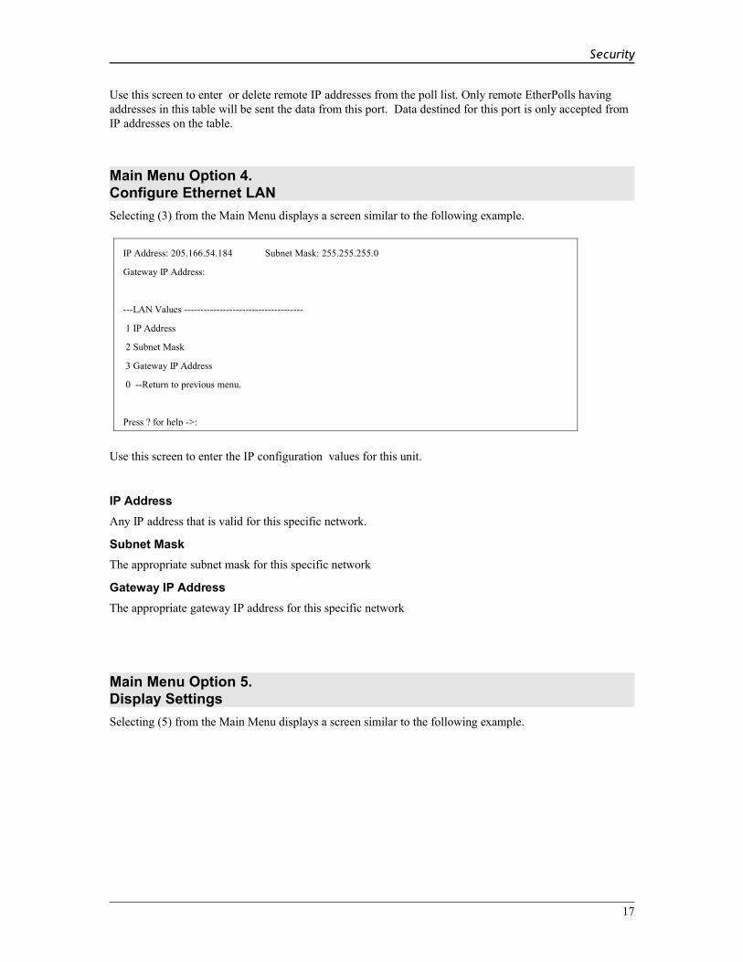
Main Menu Option 4.Configure Ethernet LANSelecting (3) from the Main Menu displays a screen similar to the following example.
Use this screen to enter the IP configuration values for this unit.
IP AddressAny IP address that is valid for this specific network.
Subnet MaskThe appropriate subnet mask for this specific network
Gateway IP AddressThe appropriate gateway IP address for this specific network
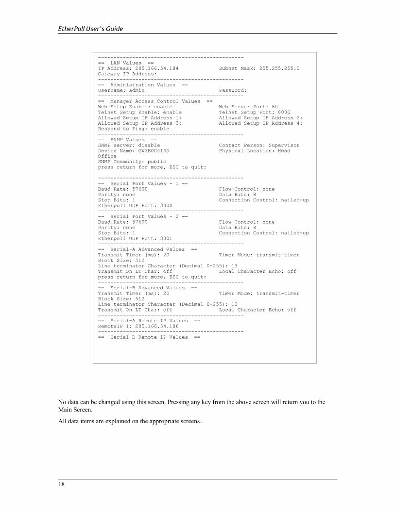
Main Menu Option 5.Display SettingsSelecting (5) from the Main Menu displays a screen similar to the following example.
17
IP Address: 205.166.54.184 Subnet Mask: 255.255.255.0
Gateway IP Address:
---LAN Values -------------------------------------
1 IP Address
2 Subnet Mask
3 Gateway IP Address
0 --Return to previous menu.
Press ? for help ->:
EtherPoll User’s Guide
No data can be changed using this screen. Pressing any key from the above screen will return you to the Main Screen.
All data items are explained on the appropriate screens..
18
-----------------------------------------------== LAN Values ==IP Address: 205.166.54.184 Subnet Mask: 255.255.255.0Gateway IP Address:-----------------------------------------------== Administration Values ==Username: admin Password:-----------------------------------------------== Manager Access Control Values ==Web Setup Enable: enable Web Server Port: 80Telnet Setup Enable: enable Telnet Setup Port: 8000Allowed Setup IP Address 1: Allowed Setup IP Address 2:Allowed Setup IP Address 3: Allowed Setup IP Address 4:Respond to Ping: enable-----------------------------------------------== SNMP Values ==SNMP server: disable Contact Person: SupervisorDevice Name: GW3B00414D Physical Location: Head OfficeSNMP Community: publicpress return for more, ESC to quit:-----------------------------------------------== Serial Port Values - 1 ==Baud Rate: 57600 Flow Control: noneParity: none Data Bits: 8Stop Bits: 1 Connection Control: nailed-upEtherpoll UDP Port: 3000-----------------------------------------------== Serial Port Values - 2 ==Baud Rate: 57600 Flow Control: noneParity: none Data Bits: 8Stop Bits: 1 Connection Control: nailed-upEtherpoll UDP Port: 3001-----------------------------------------------== Serial-A Advanced Values ==Transmit Timer (ms): 20 Timer Mode: transmit-timerBlock Size: 512Line terminator Character (Decimal 0-255): 13Transmit On LT Char: off Local Character Echo: offpress return for more, ESC to quit:-----------------------------------------------== Serial-B Advanced Values ==Transmit Timer (ms): 20 Timer Mode: transmit-timerBlock Size: 512Line terminator Character (Decimal 0-255): 13Transmit On LT Char: off Local Character Echo: off-----------------------------------------------== Serial-A Remote IP Values ==RemoteIP 1: 205.166.54.186-----------------------------------------------== Serial-B Remote IP Values ==
Security
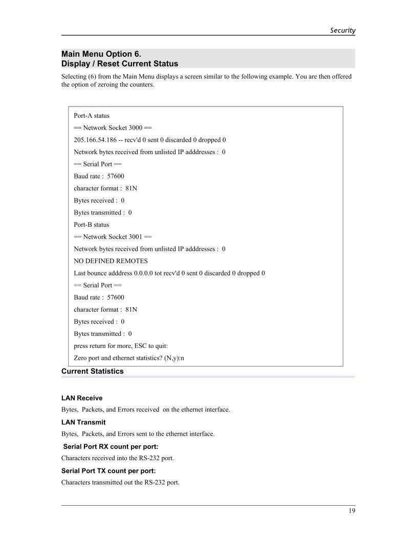
Main Menu Option 6.Display / Reset Current StatusSelecting (6) from the Main Menu displays a screen similar to the following example. You are then offered the option of zeroing the counters.
Current Statistics
LAN Receive Bytes, Packets, and Errors received on the ethernet interface.
LAN Transmit Bytes, Packets, and Errors sent to the ethernet interface.
Serial Port RX count per port: Characters received into the RS-232 port.
Serial Port TX count per port: Characters transmitted out the RS-232 port.
19
Port-A status
== Network Socket 3000 ==
205.166.54.186 -- recv'd 0 sent 0 discarded 0 dropped 0
Network bytes received from unlisted IP adddresses : 0
== Serial Port ==
Baud rate : 57600
character format : 81N
Bytes received : 0
Bytes transmitted : 0
Port-B status
== Network Socket 3001 ==
Network bytes received from unlisted IP adddresses : 0
NO DEFINED REMOTES
Last bounce adddress 0.0.0.0 tot recv'd 0 sent 0 discarded 0 dropped 0
== Serial Port ==
Baud rate : 57600
character format : 81N
Bytes received : 0
Bytes transmitted : 0
press return for more, ESC to quit:
Zero port and ethernet statistics? (N,y):n

EtherPoll User’s Guide
Remote IP Activity counts per portDisplays IP address and packet count for each remote that has exchanged data with this EtherPoll. If data has been received from a remote that is not is the IP address list, that information is also displayed along with the IP address of the first unlisted IP address. (These packets are discarded.)
Main Menu Option 7.Reset Configuration to DefaultSelecting (7) from the Main Menu will restore all values to their default values.
If using Telnet or web browser configuration, the connection will be lost when the EtherPoll reboots. To reconnect, you must use the default IP Address of 192.168.1.1 or change the EtherPoll IP address before rebooting with main menu option 7. The preferred method is to restore defaults with menu item 6, and then BEFORE REBOOTING, change the IP information using submenu 1 so your PC will still be able to connect to the EtherPoll when it reboots.
Main Menu Option 8.Save and ActivateSelecting (8) from the Main Menu will store the configuration details in the EtherPoll, and activate any pending changes.
If using Telnet, the connection may be lost when the EtherPoll reboots. If you have changed the
IP Address, you must use the new IP Address when you reconnect.
Main Menu Option 1.3Security ConfigurationThe EtherPoll contains extensive configuration security features. See Section 5, Security Configuration, for extensive details.
20
Select a function by number ->: 7
To reset to default values, Press D.
To reset Unit, press R.
Press return to exit :
---Manager Access Control Values -------------------------------------
1 Web Setup Enable [0=disable, 1=enable]
2 Web Server Port
3 Telnet Setup Enable [0=disable, 1=enable]
4 Telnet Setup Port
5 Allowed Setup IP Address 1
6 Allowed Setup IP Address 2
7 Allowed Setup IP Address 3
8 Allowed Setup IP Address 4
9 Respond to Ping [0=disable, 1=enable]
0 --Return to previous menu.

Security
Main Menu Option 9.Exit without SavingSelecting (9) from the Main Menu will exit the configuration program without saving any data you have entered.
21

EtherPoll User’s Guide
Chapter 5
Browser ConfigurationThis Chapter describes how to configure the EtherPoll using a Web Browser.
Overview
This configuration method uses your Web Browser to configure the EtherPoll. This provides a more user-friendly interface than the Telnet/Terminal method.• The EtherPoll must be installed in your LAN and have a compatible IP address before this
configuration method can be used.• Most Browsers will work. The only requirement is that they support HTML tables and forms. If your
browser uses a proxy, the proxy function may need to be disabled.• Some field details are not shown in this section. Refer to chapter 4, "Telnet/Terminal Configuration",
for more details about the entry fields.
Connection Procedure
To establish a connection to the EtherPoll, follow this procedure:
1. Install the EtherPoll in your LAN as described in Chapter 2. Ensure that the EtherPoll is powered on.
4. Start your Web browser.
5. In the Address box of your browser, enter the following:http://IP_Address
(IP_Address is the IP address of the EtherPoll)For example, if the default IP address has not been changed, then you would enter the command:
Http://192.168.1.1
If you can't connectIf the EtherPoll does not respond, check the following:• The EtherPoll is properly installed, LAN connections are
OK, and it is powered ON.• Check that your PC is using a compatible IP Address and
Network Mask.In Windows, the IP Address and Network Mask can be checked by using Control Panel-Network to examine the Properties for the TCP/IP protocol. If your PC is NOT using an IP Address within the range 192.168.1.2 to 192.168.1.254, with a Network Mask of 255.255.255.0, it will not be able to communicate with the EtherPoll.
6. Once connected, you will see the first screen. Refer to the following section for details on using the Web-based interface.
22

Security
Web-based Interface
After entering the username and password (the default username is admin, there is no default password), the first screen is similar to Figure 2.
Figure 2: Sign on Screen
• Use the menu bar on the left to navigate to the desired screen.• On-line help is available on each screen.• Each screen is explained in the following sections.
23

EtherPoll User’s Guide
Serial Port Configuration Screen
Figure 3: Serial Port Configuration Screen
This screen allows you to configure the Serial Port on the EtherPoll. The settings used should match the device connected to the serial port of the EtherPoll. • Consult the documentation of your serial port device to determine the appropriate settings to match the
device connected to this port.• Connection Control Mode, See Section 6. Operation for details on how to set this. Normally “From
Interface”.• RTS Toggle is used with radio transmitters. See Appendix B for more information if this is required.
24

Security
Port Activity Screen
Figure 4: Port Activity Screen
This screen displays details about the data currently being transmitted or received, either through the LAN or each Serial port. The display is updated every 10 seconds.
Data - Network Per Network Port
Packets received: Number of packets received by the EtherPoll through the LAN connection.
Packets Transmitted Number of packets transmitted by the EtherPoll through the LAN connection.
Network Bytes Received from Unlisted Addresses
This is the number of bytes received from IP addresses that are not in this ports' poll list. This should be zero in a properly functioning system. These packets are discarded.
Packets with Errors Number of packets transmitted or received by the EtherPoll through the LAN connection which contained errors. (Should be zero)
Data - Serial Port
Bytes Received
Number of bytes received, through the serial (RS232) connection, from the Serial port device
Bytes Transmitted
Number of bytes transmitted through the serial (RS232) connection to the Serial port device (or PC, if in Client mode).
Data – Remote IP Addresses
Remote IP Address
Number of bytes transmitted to that address
25

EtherPoll User’s Guide
LAN Receive, LAN Transmit
Total LAN bytes in and out the ethernet port
Total packets received, transmitted, and in error. This includes management packets.
Serial Port Advanced Configuration Screen
Figure 5: Advanced Configuration Screen
These settings affect the EtherPoll's internal buffer, which is used for temporary storage of data, and how some characters are processed. These values strongly affect efficiency and throughput. They may be “tuned” for your application.
Transmit Timer (msec)
When in Timer Mode, the maximum time period data will be stored in the buffer before being sent.
When in Idle Timeout Mode, the time that the RS-232 port must be idle before data in the buffer is transmitted to the ethernet port.
Allowable values range from 1ms to 10,000ms (10 seconds). Default is 20 ms.
Timer Mode When set for Transmit Timer, a free-running clock triggers the EtherPoll to send a packet of data at every tic if there is any data its buffer.
When set for Idle Timeout a packet of data is transmitted to the ethernet when there is not RS-232 data received for the specified idle time and any data is in the buffer.
26

Security
Block Size (bytes)
The size of the ethernet packet buffer. The minimum value is 1 byte, the maximum 4096 bytes (4 K). ). Note that ethernet packets are at least 64 bytes long, so extremely small values are quite inefficient.
Flow OFF buffer level (%)
If the amount of data stored in the buffer reaches this point, and the EtherPoll is unable to transmit the data, then no further input will be accepted from the serial port. The RS-232 port will be “flowed off”. Under normal operation, this will not happen.
Flow ON buffer level (%)
Once flow control has stopped input characters, the "no-input accepted" mode will continue until the EtherPoll has transmitted enough data to reduce the buffer contents to this point.
Line terminatorcharacter (decimal)
Enter the ASCII/ANSI number (1..128) to represent the Line Terminator Character. The Line Terminator Character causes any data in the buffer to be transmitted immediately when the character is received, provided that the following setting (Transmit on LT Char) is ON. The default value is 0x13, a carriage return character.
Transmit on LT char
When this setting is ON, any data in the buffer will be sent immediately upon receipt of a Line Terminator Character (see above). When this setting is OFF, the Line Terminator Character has no effect. This should normally be set to OFF for SCADA networks.
Transmit filter mode
This setting turns the filter function ON or OFF. If ON, when a CR/LF (Carriage Return, Line Feed) character pair is received, it is converted to a CR only. CR/LF pairs are normally used in the MS-DOS environment to mark the end of a line, but may cause problems in other environments which expect a CR only. CR/NULL character pairs are also converted to a CR only. If this setting is OFF, then no conversion is done. It is normally OFF for SCADA networks.
Local character echo
If ECHO is ON, all characters received from the serial port are echoed back out that port when connected.If ECHO is OFF, the EtherPoll will not echo input characters. This mode should be used if any messages from the EtherPoll would create interference with other software.
27
EtherPoll User’s Guide
LAN Configuration Screen
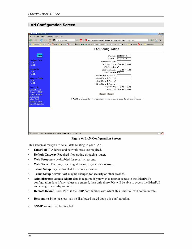
Figure 6: LAN Configuration Screen
This screen allows you to set all data relating to your LAN.• EtherPoll IP Address and network mask are required.• Default Gateway Required if operating through a router. • Web Setup may be disabled for security reasons.• Web Server Port may be changed for security or other reasons. • Telnet Setup may be disabled for security reasons.• Telnet Setup Server Port may be changed for security or other reasons.• Administrator Access Rights data is required if you wish to restrict access to the EtherPoll's
configuration data. If any values are entered, then only those PCs will be able to access the EtherPoll and change the configuration.
• Remote Device Listen Port is the UDP port number with which this EtherPoll will communicate.
• Respond to Ping packets may be disallowed based upon this configuration.
• SNMP server may be disabled.
28

Security
Data - EtherPoll
IP Address: The IP address of this EtherPoll device on your LAN in dotted decimal format. The default IP Address is 192.168.1.1
Note: If you change the IP Address, the connection will be lost when you "Save". You must reconnect using the new IP Address.
Network Mask: The network mask indicates what class of TCP/IP network you have. The default value (255.255.255.0) is for a class "C" network, with up to 255 users. This value should work in small networks. If in doubt, consult your network administrator.
Gateway IP Address:
If your LAN contains a router, enter the IP Address of the Router. Otherwise, leave this value at 0.0.0.0
Data – Telnet Configuration
Telnet configuration enable and port
This device may be configured by a telnet connection on the given port. Some installations require higher security and disable telnet configuration.
Data - Administrator Access Rights
Manager IP Address[1] to [4]
Enter the IP Addresses of the PCs which you wish to have access to the EtherPoll configuration data. If these are left blank (default) then all PCs have access.
Data - Remote Device
Remote IP Port This is the port with which the EtherPoll will send and receive data. The default is 3000.
Data – Web ServerWeb server configuration enable and port
This device may be configured by a web server on the given port. Some installations require higher security and disable web server configuration.
29

EtherPoll User’s Guide
SNMP Configuration Screen
Figure 7: SNMP Configuration Screen
Overview
This screen may be ignored if SNMP is not used.
These are text fields, commonly used in SNMP (Simple Network Management Protocol) Programs to identify this device when browsing the network.
These values have no effect on the data operation of the EtherPoll. Other standard MIB values are returned to the SNMP manager along with this information. The EtherPoll may not be configured using SNMP.
The MIB file is available from the DCB website.
30

Security
Configure Remote IP Addresses Screen
Figure 8: IP Addresses Configuration Screen
Overview
This screen is used to add or delete remote device IP addresses for each serial port.
These are the IP addresses of all devices this serial port on the EtherPoll will communicate with. The EtherPoll will discard any packet received from a device that is not on this list.
Up to 32 remote device addresses are allowed.
Every packet received into the serial port will be forwarded to all IP addresses in this table.
31

EtherPoll User’s Guide
Configuration Summary Screen
Figure 9: Configuration Summary Screen
Operation
• This screen displays all current settings for this EtherPoll
Data
All values on this screen are described in earlier sections.
32

Security
Administrative Tools Screen
Figure 10: Administrative Tools Maintenance Screen
Overview
This screen contains command buttons for a multitude of administration and diagnostic tools. With it, you may:
• Change the administration login user name and password.
• Save or load a new configuration file.
• Upload a new firmware image.
• View firmware version and other information.
• Reset all configuration settings to factory default
• Perform a "Ping" from the EPL-2 to any other IP device.
• Perform a "Traceroute" from the EPL-2 to any other IP device.
• "Sniff" packets on the ethernet interface. Only packet header information is shown.
• Reboot the unit.
• Reset the system clock. Note that there is no hardware clock in this unit.
33

EtherPoll User’s Guide
Admin Password
Admin Password ScreenAccess to the Web Server is protected by HTTP Basic Authentication. This is a simple methodology where the Web Server will require a Web Browser to provide a username and password for each page requested. The Web Browser will typically ask the user to enter the username and password once, then will remember it for the duration that the Web Browser is running.
The Administration screen allows you to change the user name and password for the router administrator. This is the only user allowed to configure the router. If you forget the administrator name or password, the router can only be configured by returning it to factory defaults as described in the quick start chapter.
Fields• User Name
This field may be a string of 0 to 15 printable characters. Do not use space or control characters. If you leave this field blank, you will need to enter a blank username during authentication.
• Old Password In order to change the username and password, you must know the old password. When making a change, enter the current password in this field.
• New PasswordWhen changing the username and password, this field provides the new password. It may be a string of 0 to 15 characters. If you leave this field blank, you will need to enter a blank password during authentication.
Notes• If you forget your username or password, you can use the Serial Port Setup to erase the current
settings.• Security Note: HTTP Basic Authentication may be easily hacked if the attacker has the ability to sniff
network packets. The username is transmitted in the clear and the password is transmitted in an obfuscated but easily reversed format.
34

Security
Set Clock
Set Clock Screen
This form allows you to set the unit's software clock. The setting will take effect when you "Activate Changes".
35

EtherPoll User’s Guide
Fields
• Year Year in the range 2000 to 2035.
• Month Numeric value of month in the range 1 to 12.
• Day Day of month in the range 1 to 31.
• Hour Hour of the day in the range 0 to 23.
• Minute Minutes in the range 0 to 59.
Notes• If you save the time to non-volatile memory, the clock will be set to the specified time at each reboot.
• The EEB-2 does not contain a real-time clock, nor has the ability to remember the current time across reboots. The software clock is used for time stamping log entries.
• The default values shown on this screen are the “boot” values… not the current time. Set the values for the time to be when the unit is next restarted.
Set All Defaults
Set All Defaults Screen
This form will allow you to set all configuration parameters to their default value. Before you "Activate Changes", you should configure the interface that
36

Security
you are using to access the unit. Otherwise, the ethernet interface will be configured with the IP address of 192.168.0.1.
Ping, Traceroute, Sniffer Tools
Typical Tool Screen
These screens provide tools that are used to diagnose network problems. All are similar to the Traceroute screen shown above. Once the button is activated, the tool runs until completion, which would be receipt of four ping packets or a valid traceroute, or a timeout. The packet sniffer runs until 100 packets are captured or 30 seconds elapse
37

EtherPoll User’s Guide
Transfer Configuration File
Configuration File Screen
This form will allow you to copy the unit's configuration to a file on your PC. You can also use the form to transfer a configuration file from your PC to the unit.
Fields• File to Transfer
This is the name of the configuration file on your PC to be transferred to the unit.
• Transfer file to PC (action)Transfers the current configuration file to this PC.
• Transfer file to the unit (action)Transfers the named file to the router.
Notes• The configuration file is a specially formatted text file. It may be edited with any text editor.
• You may save multiple configuration files on the PC by using different names for them.
• After transferring a configuration file to the router, you may either activate the changes (with the activate screen), or store the changes (with the store configuration screen). If you activate the changes, the router will immediately begin using the new configuration. If the changes are stored, the router will use the new configuration only after a reboot or reset.
• Be sure that you can access the router using its new configuration if you activate the new configuration. Otherwise, it may be necessary to return to the old stored configuration with a reset.
38

Security
Firmware Upload
Firmware Upgrade Screen
This form will allow you to load new firmware into the EPL-2. The firmware will be saved to non-volatile memory, replacing the current firmware.
Fields• File Name
This is the name of the firmware image file to be transferred to the unit.
• Upgrade Firmware (action)Pressing this button transfers the firmware image to the unit and upgrades it.
NotesYou should only use a firmware image obtained from DCB.
39
EtherPoll User’s Guide
System Reboot
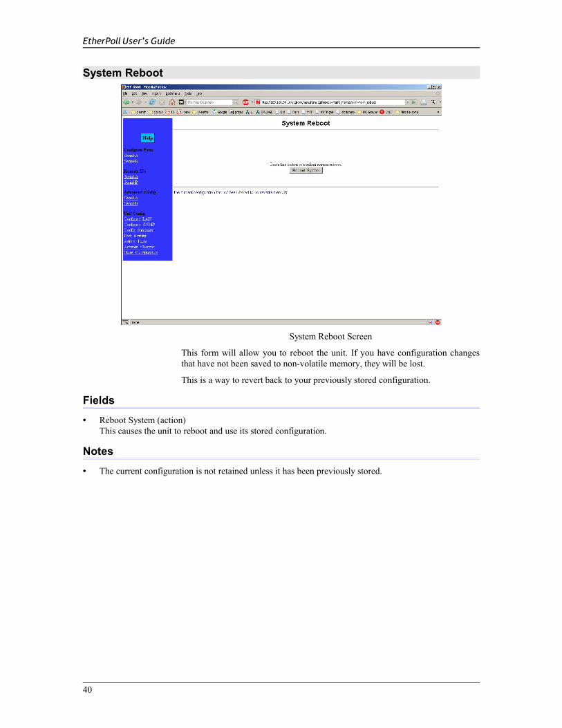
System Reboot Screen
This form will allow you to reboot the unit. If you have configuration changes that have not been saved to non-volatile memory, they will be lost.
This is a way to revert back to your previously stored configuration.
Fields• Reboot System (action)
This causes the unit to reboot and use its stored configuration.
Notes• The current configuration is not retained unless it has been previously stored.
40
Security
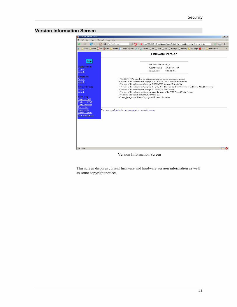
Version Information Screen
Version Information Screen
This screen displays current firmware and hardware version information as well as some copyright notices.
41

EtherPoll User’s Guide
Chapter 6
SecurityThis section discusses configuration options that restrict configuration as well as overall security issues.
Overview
Data SecurityThe EtherPoll uses the industry standard UDP/IP protocol. Since UDP/IP is a well known standard, its security vulnerabilities are also well known and may be exploited. Several EtherPoll options are available to enhance the inherent security of your EtherPoll network. However, since network security is a moving target and absolute security is never achievable, every network installation should be designed and implemented with care to minimize security risks in a way that is appropriate for the application and perceived risks.
Configuration SecurityThe EtherPoll may be configured with several levels of security configuration and authentication. These restrict the ability of an unwanted user from changing the configuration of the EtherPoll. They do not restrict the ability of a remote device to deliver packets to the EtherPoll's data port, only using the encryption feature does that.
At the level 0, any workstation may be used to configure the EtherPoll via either telnet or web browser configuration. Level 1 restricts configuration to workstations claiming to be from one of four IP addresses previously stored in the EtherPoll. Either web-based or telnet configuration is allowed. Level 2 disables remote configuration using web browser, telnet, or SNMP in any combination. Level 3 requires a user name and password for remote configuration. Combinations of Level 2 and Level 3 are possible (ie. One may disable web browser configuration and SNMP and require a username/password for telnet configuration. The most secure method would be to disable all remote configuration.
The EtherPoll may always be configured using the direct connected terminal method. This requires physical access to the hardware, and pressing the configuration button while a terminal (or PC) is connected to the serial port.
Configuration Level 0:
No specific security configuration is required. Make sure that no IP addresses have been entered in menu item 2, "Set Manager/Telnet IP Address" screen (or the "Administrator Access Rights of the web browser "Configure LAN" screen). Also, any user name/password pairs that may have been entered on the terminal configuration/telnet "Security Configuration" screen should be cleared.
42

Security
Configuration Level 1:
Using any configuration method, configure Administrator Access IP addresses. Enter the IP addresses that should have the ability to change the EtherPoll configuration. If configuring this remotely, insure that the workstation you are using is one of the valid addresses.
Configuration Level 2:
Using telnet or direct connection configuration, selectively enable or disable remote configuration via Telnet, via web browser, and SNMP. This setting may not be performed from the web configuration screen.
Configuration Level 3:
Configure Level 1 and Level 2 security as needed. Using the telnet or direct connection configuration, enter up to three user name and password pairs. If there is at least one user name in this list, then a password prompt will be issued upon establishing a telnet configuration session.
There may be up to 3 user names and passwords configured. If no users are configured, password protection is disabled. User names and passwords are limited to 8 characters each. There is a six failed login attempt limit. After six failed attempts in a row, the unit will lock out all logins for a period of about 10 minutes.
Each user name has an associated user ID or index. The user with ID 1 is considered the master user. It has the ability to change the other user names and passwords. The other two user ID's are limited to only changing their own user name and password. All users may modify any other system parameters.
43

EtherPoll User’s Guide
Chapter 7
OperationThis Chapter explains how to use the EtherPoll, once it is installed and configured.
Normal Mode• All EtherPolls must be connected as described in Chapter 3. Configuration is complete, and serial port
configurations match the associated serial port device (Polling host or RTU). LAN configuration is complete with appropriate IP addressing.
• Power up all EtherPolls and associated hardware.• Start the polling program on the polling host computer. It should automatically poll each RTU
connected to an EtherPoll whose IP address was stored during configuration of the host EtherPoll.• The serial DCD input must be HIGH or Forced ON for the unit to send and receive packets.
Broadcast Mode• Install and connect the EtherPolls and Serial Port Devices as described above.• Send some characters from a PC or terminal device connected to the host EtherPoll to its RS-232 port. • The characters should appear on the RS-232 port of all EtherPolls whose addresses are configured in
the host EtherPoll IP address list.• DCD must be HIGH or Forced ON for the unit to send and receive packets.
Point-to-Point Mode• This is similar to the above operations, however only ONE remote IP address is configured into each
EtherPoll.• DCD must be HIGH or Forced ON for the unit to send and receive packets.
RTS Toggle Feature• This feature is sometimes used to key the push-to-talk line on radio transmitters and specialty modems.• One of the above normal modes is used.• DCD must be HIGH or Forced ON for the unit to send and receive packets. • When a frame of data is in the serial output buffer, the RTS signal is asserted prior to transmitting the
data. Approximately 5 msec. after the data is sent, RTS will again be lowered.
44

Security
45

Chapter 8
TroubleshootingThis chapter outlines some problems that may occur during installation or operation and some possible solutions to them.
If you follow the suggested troubleshooting steps and the EtherPoll still does not function properly, please contact your dealer for further advice.
Hardware Problems
Before anything else, check that all cables are wired correctly and properly connected. If connecting to a 9 pin PC port, a crossover (null modem) cable is required.P: All the EtherPoll’s LEDs are off.S: Check the power supply or power connection.
P: When using 10/100Base-T cabling, the EtherPoll unit does not work.S: Check the Hub’s link LED for the port to which EtherPoll is connected. If it is off, make sure the
network cable between the EtherPoll and hub is in good condition.
46

Troubleshooting
Can't Connect via the LAN
P: Can't connect to the EtherPoll using Telnet or Web Browser.S: Check the following:• Start troubleshooting from a known state. Power the EtherPoll OFF and ON to reboot.• “Ping” the EtherPoll to see if it responds. From the Windows command prompt or “Run” dialog box,
use the command:
ping IP_AddressWhere IP_Address is the IP Address of the EtherPoll (e.g. ping 192.168.1.1 ). If it does not respond, then check all LAN connections. If the LAN connection are OK, the problem is in the LAN addresses or routing. You should be able to ping all EtherPolls. The most common problem cause is incorrect IP addressing. Make sure the workstation and EtherPolls have compatible IP addresses.
• If using a LAN without routers, you can connect to the EtherPoll ONLY IF your PC and the EtherPoll are using IP Addresses from the same address block. The EtherPolls default IP Address (192.168.1.1) requires that your PC is using an address from the address block 192.168.1.2 to 192.168.1.254, and a Network Mask of 255.255.255.0. If a router is between the devices, a gateway address must be configured in both devices.
Check your PC's IP Address using Control Panel - Network - TCP/IP (Adapter) Properties or Windows98 WINIPCFG.EXE . If you are using a different Address block, use Terminal Mode configuration to set a compatible IP Address in the EtherPoll.
• It may be that your "arp table" contains invalid entries. You can clear the "arp table" by rebooting, or, on Windows95 , by typing the following command at the command prompt or Run dialog box.: arp -d
• Check that you have used the correct port address on all units. The default port addresses are “3000” and "3001"
• MOST EtherPoll connection problems are due to incorrect RS-232 wiring. The second most common errors are incorrect IP addressing on either the EtherPoll or on the PC used for testing.
• In some cases, “smart” hubs and switches must be power-cycled to clear their internal arp cache. This is often a problem on test bench setups where IP addresses are moved between different equipment or a unit is moved between ethernet switch receptacles.
47
EtherPoll User’s Guide
Other Problems
P: Can’t run the configuration program using a serial cable connection.S: Check that:• The communication parameters are set properly. • Disconnect and reconnect the power supply to the EtherPoll.• Power is available... a LED is on.• The terminal program is operating properly. Try a loopback connector at the EtherPoll end of the cable
to verify program operation and the proper COM: port.• The most common problems causing this symptom are incorrect RS-232 wiring or the Windows
Hyperterm program not operating correctly. First, restart Hyperterm.
P: The “host” EtherPoll doesn’t automatically send data to the “RTU” EtherPolls.S: Check that:• A workstation on the host EtherPoll LAN can successfully ping all remotes.• If a firewall is between the EtherPolls it must pass the ports in use for UDP. • The EtherPolls should either be configured for “Pin 6 Control” forced ON or the interface must be
wired in such a way that that pin 6 is asserted.• The “RTU’s” IP addresses were correctly entered into the “HOST’s” EtherPoll IP Address list.• The Gateway IP Address is set correctly.• The Subnet Mask is set correctly.• The communication parameters between the host computer and the local (“host”) EtherPoll match. • The communication parameters between the serial port RTU device and the remote (“RTU”) EtherPoll
match.
P: Throughput is extremely low. There seems to be a long delay when transmitting data.S: The first time an EtherPoll sends data to a remote device, it must ARP that device’s IP address. If that
device does not exist on the network, the ARP command is repeated, and allowed to timeout. If non-existant devices are configured in the EtherPoll’s remote address table, then the addresses are ARP’d (and allowed to timeout) every time there is data to send. This problem does not occur after a device has been located at least once, as the EtherPoll’s internal ARP table never times out…. It’s only a problem for non-existant devices after a power cycle.
• Do not configure IP addresses in the remote device table for devices that do not exist.
P: The EtherPoll's IP Address is unknown. Is there any way of finding it, other than using Terminal Configuration mode?
• S: No, it must be restarted in terminal configuration mode with a terminal connected. The existing IP address will be displayed in the startup sequence.
48

Troubleshooting
Checking Device Operation
Once the EtherPoll is installed on your Network, you can connect to it using Telnet, to verify its operation. The procedure is as follows.
1. Use telnet to connect to the EtherPoll with the command:telnet IP_Address 8000
2.Where IP_Address is the IP Address assigned to the EtherPoll, and 8000 represents the Port number.
The port number is “8000” for configuration, but “3000” is the default for normal operation. The actual data connections to the EtherPoll on port 3000 are not TCP/IP as used with telnet programs, but are UDP/IP, so you can not telnet to the EtherPoll to send test data through it.
If the “Manager IP Addresses” have been entered in the EtherPoll, then only a PC having one of those addresses can change the configuration.
3. Choose item 5 (“Display Settings”) from the Main Menu, and examine the data shown. See page 16 for an explanation of each of the data items.
49

Appendix A
Specifications
EtherPoll Specifications
• Flash Memory: 4 Mbytes• SRAM: 8 Mbytes• LAN Interface: 10/100BaseTx, Autosense• RS-232: Two male DE-9 connectors (PC –9 Pin)• RS-232 speed: Up to 230.4.2 Kbps• CPU: Motorola Coldfire 5272 CPU 66 Mhz• OS: uClinux• Power: 9 to 12 VDC 600mA or Optional power supplies• Switch: Configuration, Reset• LED:8 (Status, Serial Activity, LAN Activity, Power)• Default IP address: 192.168.1.1• Browser Management port: 80• Telnet Management port: 8000• Default Receive ports: 3000, 3001• Operational Temperature -40C to +70C
50
Specifications
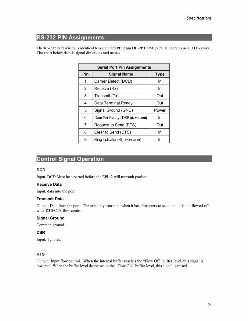
RS-232 PIN Assignments
The RS-232 port wiring is identical to a standard PC 9 pin DE-9P COM: port. It operates as a DTE device. The chart below details signal directions and names.
Serial Port Pin AssignmentsPin Signal Name Type
1 Carrier Detect (DCD) In
2 Receive (Rx) In
3 Transmit (Tx) Out
4 Data Terminal Ready Out
5 Signal Ground (GND) Power
6 Data Set Ready (DSR)(Not used) In
7 Request to Send (RTS) Out
8 Clear to Send (CTS) In
9 Ring Indicator (RI) (Not used) In
Control Signal Operation
DCDInput DCD Must be asserted before the EPL-2 will transmit packets.
Receive DataInput, data into the port
Transmit DataOutput, Data from the port. The unit only transmits when it has characters to send and it is not flowed-off with RTS/CTS flow control.
Signal GroundCommon ground
DSRInput. Ignored
RTSOutput. Input flow control. When the internal buffer reaches the “Flow Off” buffer level, this signal is lowered. When the buffer level decreases to the “Flow ON” buffer level, this signal is raised
51

EtherPoll User’s Guide
CTSInput. When Flow Control is set for CTS/RTS, lowering this signal will halt data flow from the RS-232 port.
Ring IndicatorNot used
CABLES
Commonly used cable connections:
To PC 9-pin COM: port
Port
1,6234578
P C
432
1,6587
This null-modem crossover cable is easily made by combining “PC-Direct” and “Remote PC” adapter hoods with a straight-through line cord.
EtherPoll to Modem
Use any commercially available PC-to-modem cable.
Ethernet Cross-Over Cable
Used to connect two EtherPoll ethernet connections “back-to-back” without using an ethernet hub for test purposes. Also used to connect a EtherPoll directly to a PC’s LAN connection for testing.
WHT / ORGORG / WHTWHT / GRNBLU / WHTWHT / BLUGRN / WHTWHT / BRNBRN / WHT
RJ-45
12345678
RJ-45
361N/CN/C2N/CN/C
52

Specifications
Appendix B
Advanced OperationThis Appendix explains the EtherPoll's operation in more detail. This information is not needed in most applications.
Introduction
The EtherPoll must be configured with proper ethernet addressing and serial port parameters. It has been used successfully with common SCADA protocols such as Modbus ASCII, Modbus RTU, DNP3, and other 8-bit asynchronous protocols. This section explains how the EtherPoll operates for the technician who needs to understand the internals in more detail.
Description and Behavior
Ports used by the EtherPoll
The EtherPoll uses 3 ports, as follows:
Port Description
Configurable default - 3000 & 3001
EtherPoll listens at ports 3000 and 3001and offers a raw UDP connection. This port number is configurable.
8000 Provides a telnet configuration service for all modes.
Normal Operation ModesIn Normal Mode, the EtherPoll runs under the UDP/IP network protocol. It will listen on a configured port number. The server will wait for incoming data after initialization.
The EtherPoll constantly checks for data on both Ethernet and Serial Ports.
If data from the Ethernet network is received, it will first check for a special control symbol, and then send the data to the serial port.
If data from the serial port is received, it will read the data from the serial buffer, move the data into the network buffer and send it by ethernet when the buffer is full, when it senses an idle timeout, or on the next tick of the transmit timer.
The data being sent via ethernet is packaged into UDP packets and a separate copy is sent to each IP address in the EtherPoll’s IP address list.
Each configured port number is associated ONLY with a single serial port.
Point - to - Point ModeEtherPolls configured for Point-to-Point mode function the same. The only difference between the “normal” operation and point-to-point is the number of IP addresses in the IP address list. For point-to-point operation, there is only one address in the list (the other unit’s).
53
EtherPoll User’s Guide
Broadcast ModeBroadcast mode is also identical to “normal” mode. There is simply no polling taking place over the network.
Transmit ConditionsThe EtherPoll will transmit an ethernet packet of data whenever one of the following conditions is met…• Timer is up. In Timer Mode, a free running clock triggers a transmission when it ticks if there is data
in the buffer.• Idle time is up. In Idle Timeout mode, a (configured) time period elapses with no incoming data if
there is data in the buffer.• Transmit Buffer full.
SCADA ProtocolsThe EtherPoll is protocol-transparent. It has been successfully used with many 8-bit asynchronous protocols. However, some protocols work best with specific settings. If in doubt, call Tech Support for additional information on your application.
54

Specifications
Appendix C
Open Source Software InformationThis product was designed in conjunction with Open Source Linux software..
Introduction
This product was designed and programmed with Open Source Linux software in mind. The core Linux operating system is uClinux, available from http://www.uclinux.org . DCB supports the Open Source software effort and is appreciative of the contribution many open source developers have made to the community
Other open source software used in this product may be obtained from the original developers, and is made available in accordance with GNU licensing terms.
Obtaining the Source Code
For more information on obtaining the source modules for open source code used in this product, send a written request to the following address. Code is provided on CDROM. According to GNU licensing terms, a duplication fee may be charged.
Open Source Software AdministratorData Comm for Business, Inc.2949 CR 1000 E Dewey, IL. 61840
55