manual de dosatron
TRANSCRIPT

D 8 RD 8 R 150
manuel d’utilisation owner’s manualgebrauchsanweisungmanuale d’usomanual de utilizacióngebruiksaanwijzing
manuel d’utilisation owner’s manualgebrauchsanweisungmanuale d’usomanual de utilizacióngebruiksaanwijzing
8 m3/h - 40 GPM

Quick start-up
US
VE
RS
ION
1
1 2
2
Maxi. : 46 clics/15 sec.
“ON”
© DOSATRON INTERNATIONAL / 3
Français.................................. Page 5
English.................................. Page 31
Deutsch .............................. Seite 57
Italiano .......................... Pagina 83
Español ...................... Página 109
Nederlands ............ Pagina 135
Annexes/Enclosure/Anhang ................ 160Anejos/Allegati/Bijvoegsel
WORLDWIDE - EUROPE :DOSATRON INTERNATIONAL S.A.
Rue Pascal - B.P. 6 - 33370 TRESSES (BORDEAUX) - FRANCETel. 33 (0)5 57 97 11 11Fax. 33 (0)5 57 97 11 29 / 33 (0)5 57 97 10 85e.mail : [email protected] - http://www.dosatron.com
NORTH & CENTRAL AMERICA :DOSATRON INTERNATIONAL INC.
2090 SUNNYDALE BLVD. CLEARWATER - FL 33765 - USATel. 1-727-443-5404 - Fax 1-727-447-0591Customer Service: 1-800-523-8499e.mail : [email protected] - http://www.dosatronusa.com
SERVICE CLIENTÈLECUSTOMER SERVICEKUNDENBETREUUNGSERVIZIO CLIENTIDEPARTAMENTO CLIENTELAKLANTENSERVICE

© DOSATRON INTERNATIONAL / 4 © DOSATRON INTERNATIONAL / 5
FR
Vous venez d'acquérir un Doseur Proportionnel DOSATRON.Nous vous félicitons de votre choix. Ce modèle a été élaboré grâce à l'expériencede plus de 30 années.Nos ingénieurs ont placé la série des DOSATRON largement en tête de ce que pou-vait être l'évolution technique des Doseurs Proportionnels Sans Electricité.Le choix des matériaux entrant dans leur fabrication fut des plus minutieux afin derésister aux attaques chimiques de tous ou du moins de la plus grande quantité desproduits à doser sur le marché. Ce DOSATRON se révélera, au fil du temps, commeun allié des plus fidèles.Quelques soins dispensés régulièrement sauront vous garantir un fonctionnementdans lequel le mot panne n'a plus sa place.
VEUILLEZ DONC LIRE CE MANUEL ATTENTIVEMENTAVANT DE METTRE L'APPAREIL EN SERVICE.
Important ! La référence complète et le numéro de série de votreDOSATRON figure sur le corps de pompe.Vous êtes priés d'enregistrer ce numéro dans la partieréservée ci-dessous et de le rappeler lors de tout contactou de besoin d'information avec votre vendeur.
Réf. : ................................................................................
N°Série : ........................................................................
Date d'achat : ................................................................
Notes......................................................................................................................
......................................................................................................................
......................................................................................................................
......................................................................................................................
......................................................................................................................
......................................................................................................................
......................................................................................................................
......................................................................................................................
......................................................................................................................
......................................................................................................................
......................................................................................................................
......................................................................................................................
......................................................................................................................
......................................................................................................................
......................................................................................................................
......................................................................................................................
......................................................................................................................
......................................................................................................................
......................................................................................................................
......................................................................................................................
......................................................................................................................
......................................................................................................................
Ce document ne constitue pas un engagement contractuel et n’est fourni qu’à titre indicatif. DOSATRON INTERNATIONAL se réserve le droit de modifier ses appareils à tout moment.
© DOSATRON INTERNATIONAL S.A. 2007
Français

© DOSATRON INTERNATIONAL / 6 © DOSATRON INTERNATIONAL / 7
FR
INSTALLATION PAGE
Précautions ..............................................................................................9
Installation du Dosatron ....................................................................11
Conseils d’installation ........................................................................14
MISE EN SERVICE
Première mise en service....................................................................15
By-Pass hydraulique incorporé ........................................................15
By-Pass commandé hydrauliquement............................................16
ENTRETIEN
Recommandations ..............................................................................18
Vidange du Dosatron ..........................................................................18
Nettoyage du filtre incorporé ..........................................................19
Conversions - mesures internationales..........................................19
Raccordement du tuyau d’aspiration ............................................20
Réglage du dosage ..............................................................................20
Changement des joints de la partie dosage ................................21
Changement du piston moteur........................................................24
DÉSIGNATION/RÉFÉRENCE ..........................................................25
INCIDENTS POSSIBLES ....................................................................26
GARANTIE ..............................................................................................28
SommaireCARACTERISTIQUES
Débit pratique de fonctionnement : 500 l/h mini - 8 m3 maxi [2.2 Fl oz/min - 40 US GPM]
Pression de fonctionnement : barPSI
Dosage réglable extérieurement : %ratio
Débit d'injection du produit concentré : Mini l/h - Maxi l/hUS Fl. oz/minUS GPM/max
Température maximum de fonctionnement : 40 °C [104 ° F]
Raccordement (NPT/BSP gaz mâle) : Ø 40x49 mm [1” 1/2 M]
Cylindrée du moteur hydraulique (tous les 2 clacs du piston) : environ 1.6 l [0.4224 US Gallons]
COMPOSITION DU COLIS : 1 DOSATRON / 1 support mural pour DOSATRON / 1 tuyau d’aspiration de produit concentré / 1 crépine / 1 manuel d’utilisation
ATTENTION ! Le DOSATRON n'est pas préréglé, pour cela se reporter au paragraphe REGLAGE DU DOSAGE
0.15 - 82 - 110
0.2 - 21:500 - 1:50
1 - 1600.560.70
D 8 R
ENCOMBREMENT
Diamètre : cm ["]
Haut. totale : cm ["]
Larg. hors tout : cm ["]
Poids : ± kg [lbs]
Dimensions du colis : cm["]
Poids du colis : ± kg [lbs]
18.4 [7 1/4]
59.1 [23 1/4]
31 [12 1/4]
4 [8.8]
0.15 - 82 - 110
1 - 51:100 - 1:20
5 - 4002.8
1.76
D 8 R 150
18.4 [7 1/4]
66.7 [26 1/4]
31 [12 1/4]
4.5 [10]
60 x 36.5 x 24[23 2/3 x 14 1/3 x 9 1/2]
82 x 26 x 21[32 1/4 x 10 1/4 x 8 1/4]
5.5 [12.15] 7 [15.5]

© DOSATRON INTERNATIONAL / 9© DOSATRON INTERNATIONAL / 8
FRInstallationPRECAUTIONS
1 - GENERALITES- Quand on connecte un DOSATRON,que ce soit au réseau d'eau publicou à son propre point d'eau, il estimpératif de respecter les normesde protection et de disconnexion.DOSATRON recommande un dis-connecteur afin d'éviter lacontamination de l'alimentationd'eau.- Dans le cas où l’installation seraitplus haute que le DOSATRON lui-même, un risque de retour d’eau etde produit dans le DOSATRON estpossible ; il est alors conseillé d’ins-taller un clapet anti-retour en avalde l’appareil.- Ne pas installer le DOSATRON au-dessus d’un bac d’acide ou deproduit agressif, décaler le bidon etle protéger, à l'aide d'un couvercle,d’éventuelles émanations de produits.- Tenir le DOSATRON éloigné dessources de chaleur importante et enhiver le mettre hors gel.- Ne pas installer le DOSATRON surle circuit d’aspiration de la pompemotrice (siphonnage).- L'opérateur doit se tenir face auDOSATRON et porter des lunettes et des gants de protection lors de touteintervention.
- Pour assurer la précision du dosage,le remplacement annuel des jointsde la partie dosage reste sous laseule responsabilité de l'utilisateur.- Le réglage du dosage du Dosatronest sous la responsabilité exclusivede son utilisateur. Celui-ci est tenude respecter rigoureusement lesrecommandations du fabricant desproduits chimiques.- S'assurer que le débit et la pressionde l'eau de l'installation sont enconformité avec les caractéristiquesdu DOSATRON.- L'utilisateur sera seul responsabledu choix correct des réglages duDOSATRON pour l'obtention dudosage voulu.- Une prise d'air, une impureté ouune attaque chimique du joint peutinterrompre le bon fonctionnementdu dosage. Il est recommandé devérifier périodiquement que le produit concentré à doser est bienaspiré dans le DOSATRON.- Changer le tuyau d'aspiration duDOSATRON dès que ce dernier semble détérioré par le concentrédosé.- En fin d'utilisation, mettre le système hors pression (recommandé).
Précis, simple et fiable
Piston moteur
Eau claire
Solution eau + % produit
Piston doseur
Réglage dosage (%)
Produit concentré à doser
Installé sur le réseau d’eau, le DOSATRON utilise la pressiond’eau comme seule force motrice. Ainsi actionné, il aspire le pro-duit concentré, le dose au pourcentage désiré, puis le mélangeavec l’eau motrice. La solution réalisée est alors envoyée en aval.La dose de produit injecté est toujours proportionnelle au volu-me d’eau qui traverse le DOSATRON, quelles que soient lesvariations de débit ou de pression.

L'INSTALLATION DOIT SE FAIRESANS OUTILLe DOSATRON est livré avec : - un support mural,- un tuyau d'aspiration avec crépine.- un tuyau (by-pass) Ø 6 x 9.Le support permet la fixation mura-le du DOSATRON. - Engager les queues d'aronde duDOSATRON (Fig. 1-A) dans le sup-port mural (Fig. 1-S). - Enlever les écrous (Fig. 1-E) et lesbagues crampées (Fig. 1-C) sur lesorifices d'entrée et de sortie d'eau duDOSATRON.
- Enlever les bouchons de protection(Fig. 1-B) qui obturent les orifices devotre DOSATRON avant de le raccor-der sur le réseau d'eau. - Veiller au bon positionnement àl'entrée et à la sortie du systèmed'étanchéité. Placer d'abord le jointtorique (Fig. 1-J) et ensuite la baguecrampée (Fig. 1-G). - S’assurer que l’eau s’écoule dans lesens des flêches sur l’appareil.
© DOSATRON INTERNATIONAL / 11© DOSATRON INTERNATIONAL / 10
FR1 - GENERALITES (suite)- Le rinçage (eau claire) du DOSA-TRON est impératif :. à chaque changement de produit,. avant chaque manipulation, afin
d'éviter tout contact avec des produits agressifs.
- Pour le dosage de produits agressifs,merci de consulter votre vendeuravant toute utilisation pour confir-mer la compatibilité avec le doseur.- Tout montage ou tout serrage doitêtre fait sans outil et manuellement.
2 - EAUX CHARGEES- Dans le cas d'eaux très chargées, installer impérativement en amontdu DOSATRON un filtre à tamis (ex. :300 mesh - 60 microns selon la quali-té de votre eau). Si ce filtre n'est pasinstallé, des particules abrasives cau-seront l'usure prématurée duDOSATRON.
3 - COUPS DE BELIER / SURDEBIT- Pour les exploitations sujettes auxcoups de bélier, il est nécessaired'installer un dispositif anti-bélier(système de régulation pression /débit).- Pour les installations automatisées,utiliser de préférence des électrovan-nes à ouvertures et fermetures lentes.- Dans le cas où un DOSATRON alimenterait plusieurs secteurs,actionner les électrovannes de façon
simultanée (fermeture d'un secteuret ouverture d'un autre secteur enmême temps).
4 - LOCALISATION DE L'INSTALLATION- Le DOSATRON et le produit à doserdoivent être accessibles. Leur instal-lation ne doit en aucun casprésenter un risque de pollution oude contamination.- Il est recommandé d'équiper toutesles canalisations d'eau avec un marquage signalant que l'eaucontient des additifs et porter lamention : "ATTENTION ! Eau Non Potable".
5 - MAINTENANCE- Après utilisation, il est recommandéde faire aspirer de l'eau claire (~ 1/4 litre [8 1/2 US Fl.oz]).- Une maintenance annuelle optimi-sera la longévité de votre DOSATRON.Changer les joints de dosage au moinsune fois par an, en fonction de son uti-lisation.
6 - SERVICE- Ce DOSATRON a été testé avantson emballage.- Des sous-ensembles de réparation etdes pochettes de joints sont disponibles.- Ne pas hésiter à appeler votre distributeur ou DOSATRON pour toutservice après-vente.
PRECAUTIONS (suite) INSTALLATION DU DOSATRON
A
Fig. 1E C B G J
B
S

© DOSATRON INTERNATIONAL / 13© DOSATRON INTERNATIONAL / 12
FR
ATTENTION ! Laisser la crépine à 10 cm [4”] environ du fond du bac de solution afin d'éviter d'aspirer les particules non solubles qui risquentd'endommager le corps doseur (Fig. 3).- Ne pas poser la crépine sur le sol.
NOTA : La hauteur d'aspiration est de 4 mètres maximum [13 ft].
- Raccorder le tuyau muni de sa crépine et de son lest, le plonger dans lasolution à doser.
En aucun cas le niveau de la solution ne doit être au-dessus de l'entréed'eau dans le DOSATRON, afin d’éviter tout siphonage .
INSTALLATION DU DOSATRON (suite)
10 c
m
Fig. 3
CE QUE VOUS NE DEVEZ PAS FAIRE
CE QUE VOUS DEVEZ FAIRE
▼
▼
Fig. 4
Méthode à suivre pour raccorde-ment avec tube PVC : - Procéder comme pour le raccorde-ment de tube polyéthylène oupolypropylène, mais avant de serrer,enduire de colle PVC la place qu'oc-cupera la bague crampée. - Avancer la bague crampée en posi-tion, en l'écartant avec les deuxpouces placés dans la fente (Fig. 2-C)pour ne pas racler la colle, puis procé-der au serrage de l'écrou.
NOTA : Attendre une heure avant lamise en pression du circuit. Pour toutdémontage ultérieur, il faut savoirque la colle PVC n'adhère pas à labague crampée qui est en polyacétal.
Le raccordement de l'appareil au réseau d'eau peut s'effectuer à l'aide detuyaux souples de 40 mm de diamètre intérieur fixés à l'aide de colliers etraccords à écrous tournants Ø 40 x 49 mm [1"1/2]. S'assurer que l'eaus'écoule dans le sens des flèches sur l'appareil.
Le DOSATRON est livré avec un tuyau d'aspiration (à raccourcir suivantbesoin) qui permet son utilisation avec un récipient de grande contenance.Ce tuyau doit être muni obligatoirement de la crépine et du lest.Pour le raccordement de ce tuyau, voir le chapitre correspondant.
INSTALLATION DU DOSATRON (suite)
Méthode à suivre pour raccorde-ment avec tube polyéthylène etpolypropylène :- Placer sur le tube d'entrée et desortie d'eau coupé proprement etchanfreiné, l'écrou (Fig. 2-E) et labague crampée (Fig. 2-C). - Introduire le tube jusqu'en butéedans les orifices d'entrée et de sortied'eau (Fig. 2). - Pousser jusqu'en butée la bague
crampée (Fig. 2-C) sur l'entrée, puisl'autre sur la sortie d'eau. - Serrer l'écrou (Fig. 2-E).
E
Fig. 2
C

Mise en service du DOSATRON
PREMIERE MISE EN SERVICE- Placer le levier by-pass (Fig. 7-L) surla position ON. - Ouvrir progressivement l'arrivéed'eau, le DOSATRON s'auto-amorce. - Le laisser fonctionner jusqu'à ce quele produit à doser monte dans la par-tie dosage (visualisation à travers le tuyau transparent). - Le DOSATRON émet un "clic clac" caractéristique de son fonctionnement. NOTA : Le temps d'amorçage de la solution dosée est fonction du débit, duréglage du dosage et de la longueur du tuyau d'aspiration de produit. Pouraccélérer l'amorçage, régler le dosage au maximum. Une fois l'amorçageréalisé, faire chuter la pression à zéro et régler le dosage à la valeur désirée(voir § REGLAGE DU DOSAGE).
Système de mise en route ou arrêt d'aspiration de produit : Une pression de 0.8 bar minimum d'eau de commande est nécessaire pourobtenir un bon fonctionnement du by-pass. - By-pass sur OFF (Fig. 8-L), le DOSATRON est arrêté et n’aspire pas le produit. - By-pass sur ON (Fig. 9-L), le DOSATRON fonctionne, il aspire, injecte etmélange le produit concentré dans l’eau au % choisi.
ATTENTION ! Lorsque l'on passe de la position OFF à la position ON, ilest normal qu'une petite quantité d'eau s'évacue par la queue canneléeØ 3 [1/8"] (Fig. 9-Q).
© DOSATRON INTERNATIONAL / 15© DOSATRON INTERNATIONAL / 14
FR
CONSEIL D’INSTALLATION
Surdébit (à titre indicatif) Si votre DOSATRON claque plus de 36 coups, soit 18 cycles en 15 secon-des, vous êtes en limite de capacité de débit supérieur. Pour aller au-delà,choisir un DOSATRON à capacité de débit d'eau supérieur.
Sur la canalisation d’eau, les montagespeuvent être faits en ligne (Fig. 5), enby-pass, conseillés (Fig. 6). Si votredébit est supérieur aux limites duDOSATRON, voir § SURDEBIT.
Afin de préserver la longévité duDOSATRON, il est conseillé de monterun filtre (300 mesh -60 microns) enamont de celui-ci. Cette précaution estindispensable quand l’eau est chargéeen impuretés ou particules, surtout sil’eau provient d’un forage. Le filtre estconseillé et nécessaire pour que lagarantie soit valable.
Le montage en by-pass permet l’ali-mentation en eau claire del'installation sans faire fonctionner leDOSATRON et permet le démontageaisé de celui-ci.
Pour toute installation sur leréseau d’eau potable, respectezles normes et réglementations
en vigueur dans le pays.
Clapet anti-
retourVanne Vanne
Filtre Filtre
Fig. 6Fig. 5
Fig. 7
Fig. 8 Fig. 9
F
L L Q
BY-PASS HYDRAULIQUE INCORPORÉ

© DOSATRON INTERNATIONAL / 17
FR
© DOSATRON INTERNATIONAL / 16
BY-PASS COMMANDE HYDRAULIQUEMENT
Système de mise en route ou arrêt d'aspiration de produit : Une pression de 0.8 bar minimum d'eau de commande est nécessaire pourobtenir un bon fonctionnement du by-pass. NOTA : En utilisation du by-pass télécommandé, le levier de commandemanuelle (Fig. 10-L) doit être sur la position ON.
BY-PASS COMMANDE HYDRAULIQUEMENT (suite)
Dispositif automatique anti-siphonnage du produit : - Il rétablit automatiquement la pression atmosphérique dans l'installation
en cas de dépression accidentelle* (Fig. 11). Son utilisation relève de laréglementation sanitaire en vigueur dans le pays. - Se conformer aux dispositions prévues. - Pour le mettre en service, dévisser l'écrou (Fig. 11-E) enlever la rondellemétallique pleine (Fig. 11-P) et la remplacer par la rondelle creuse (Fig. 11-C) qui se trouve dans le colis. - Revisser l'écrou (Fig. 11-E).
Mise en by-pass télécommandé : - Ouverture de l'électrovanne. NO (normalement ouvert) : 1 vers 2 > Utilisation : Arrivée eau de commande
du by-pass Mise en by-pass (arrêt du DOSATRON) 3 > Echappement fermé
Mise en route du DOSATRON : - Fermeture de l'électrovanne. NF (normalement fermé) : 2 vers 3 > Echappement : Echappement eau
de commande à l'extérieur Mise en route du DOSATRON 1 > Pression en attente
Fig. 10
Fig. 11
F
C
E
Bille
Rondellecaoutchouc
P
F
Q : Queue cannelée Ø 3 [1/8"] (livrée avec le DOSATRON)
Fluide de commande (air oueau) Pression : de 0.8 à 8 bar
O : Electrovanne à 3 voies en L
(non livrée avec le DOSATRON)
T : Tuyau souple Ø 6 x 9[1/4" ID] x [3/8" OD]
*exemple : cas où la sortie doseur est plus basse que l’entrée.

Fig. 12
Joint
NETTOYAGE DU FILTRE INCORPORE 500 microns - 32 mesh
Démontage du filtre- Fermer l'arrivée d'eau etchuter la pression àzéro. Avant d’accéder aufiltre, suivre les pro-cédureschronologiques dedémontage décri-tes au §CHANGEMENT DUPISTON MOTEUR.- Enlever la partie dosage.
- Dévisser la cloche à la main etla retirer (Fig. 13). - Enlever le piston moteur (Fig. 14-M). - Sortir le filtre (Fig. 14-F). - Enlever le joint d'étanchéité (Fig. 14-N). - Nettoyer le filtre et le joint à l'eau claire.
Remontage du filtre - Avant le remontage, s'assurer que les portéesdu filtre et celles du joint d'étanchéité (Fig. 14-N) sur le corps et sur la clo-che sont propres. Remplacer le joint si nécessaire. - Graisser le filetage du corps de pompe (graisse silicone). - Opérations inverses du démontage. Important : dans tous les cas, le serrage doit s’effectuer à la main.
CONVERSIONS - Mesures internationales
Principe : Réglage à 1% ⇒ 1/100 = 1 volume de produit concentré pour100 volumes d’eau.Ex. : Réglage à 2 % ⇒ 2/100 = 2 volumes de produit concentré pour 100 volumes d’eau.Rapport ⇒ 1/50.
© DOSATRON INTERNATIONAL / 19
FR
© DOSATRON INTERNATIONAL / 18
EntretienRECOMMANDATIONS
1 - Lorsque vous utilisez des produitssolubles mis en solution, il estconseillé de démonter périodique-ment la partie dosage complète (§CHANGEMENT DES JOINTS DEDOSAGE).Rincer abondamment les élémentsde la partie dosage à l'eau claire, lesremonter en ayant au préalable graissé avec unegraisse au silicone le joint repéré (Fig. 12).2 - Une prise d'air, une impureté ou une attaquechimique du joint peut interrompre le bon fonction-nement du dosage. Il est recommandé de vérifierpériodiquement que le produit concentré à doserest bien aspiré dans le DOSATRON.3 - Avant la remise en service du DOSATRON endébut de période d'utilisation, sortir le pistonmoteur et le tremper dans de l'eau tiède (< 40°C)pendant quelques heures. Cette opération permetd'éliminer les dépôts ayant séchés dans le pistonmoteur.
VIDANGE DU DOSATRON (dans le cadre d’une mise hors gel)
- Fermer l'arrivée d'eau et faire chuter la pression à zéro. - Enlever la partie dosage. - Enlever la cloche et le moteur, § NETTOYAGE DU FILTRE INCORPORE. - Débrancher les raccords à l'entrée et à la sortie d'eau. - Vider le corps principal après l'avoir enlevé du support mural. - Procéder au remontage en ayant au préalable nettoyé le joint d'étanchéi-té (Fig. 14-N page suivante).
Périodicité : Une fois par mois suivant utilisation.
Fig. 13
Fig. 14
M
N
F

REGLAGE DU DOSAGE (suite)
© DOSATRON INTERNATIONAL / 21
FR
© DOSATRON INTERNATIONAL / 20
RACCORDEMENT DU TUYAU D’ASPIRATION
Dans le cas de raccordement sur un DOSATRON déjà utilisé, consulter impéra-tivement le § PRECAUTIONS.
- Dévisser l'écrou (Fig. 15-E) du bas de la partie dosage et enfiler le tuyaud'aspiration dans l'écrou. - Pousser à fond le tuyau sur l'embout cannelé et revisser l'écrou à la main. - Pour le tuyau d'aspiration Ø 20 (D8RV et D8R150), dévisser à l’aide d’untournevis, le collier (Fig. 16-C) monté sur le tuyau d’aspiration. - Enfiler le tuyau à fond sur l’embout cannelé, revisser le collier.
Modèle D8R150- Desserrer la bague de blocage (Fig. 17-B). - Visser ou dévisser la douille de réglage(Fig. 17-D) pour amener le haut de la douil-le sur le repère du dosage souhaité. - Resserrer la bague de blocage (Fig. 17-B).
RAPPEL : La quantité de produit injecté estproportionnelle à la quantité d’eau qui entredans le DOSATRON. 1% ⇒ 1/100, rapportde 100 volumes d’eau + 1 volume de produitinjecté.
REGLAGE DU DOSAGE (hors pression)
ATTENTION ! Ne pas utiliser d’outil.Le réglage du dosage doit-être effec-tué hors pression, après fermeturearrivée d’eau.Modèle D8R- Desserrer la bague de blocage (Fig.17-B). - Visser ou dévisser la douille de réglage(Fig. 17-D) pour amener le haut de ladouille sur le repère du dosage souhaité. - Resserrer la bague de blocage (Fig. 17-B).
Fig. 15
ø 12 ø 20
D8R150D8R
ø 20(option “V”)
Fig. 16
C
E
Fig. 17
B
D
Fig. 17
B
D
CHANGEMENT DES JOINTS DE LA PARTIE DOSAGE (hors pression)
Périodicité : au moins une fois par an.ATTENTION ! Ne pas utiliser d’outil ou d’ustensile métallique.
CONSEIL : Avant tout démontage de la partie dosage, il est conseillé defaire fonctionner le DOSATRON en aspirant de l’eau claire afin de rincer lesystème d’injection. Ceci évite tout risque de contact avec des produits pou-vant se trouver dans la partie dosage. Porter des lunettes et des gants deprotection lors de toute intervention de cette nature !
METHODE POUR RETIRER UN JOINTFig. 18 : Entre le pouce et l’index, pincer lapièce et le joint ; le repousser vers le côtéopposé pour le déformer.Fig. 19 : Accentuer la déformation poursaisir la partie du joint qui dépasse, déga-ger ensuite ce dernier hors de sa gorge.Nettoyer la portée de joint sans outil.Le remontage se fait à la main.Il est très important que le joint ne soit pasvrillé une fois en place car l’étanchéité neserait pas assurée.
Fig. 18
Fig. 19

CHANGEMENT DES JOINTS DE LA PARTIE DOSAGE (suite)
NETTOYAGE ET REMONTAGE DU CLAPET D’ASPIRATION
Fig. 21
Fig. 22
- Fermer l’arrivée d’eau et faire chuter la pression à zéro. Modèle D8R- Dévisser l’écrou (Fig. 20/21-E) et enlever le tuyau d’aspiration.- Pour le tuyau d'aspiration Ø 20 (option V), dévisser à l’aide d’un tournevis,le collier (Fig. 21-C) monté sur le tuyau d’aspiration.- Dévisser et enlever l’écrou noir (Fig. 20/21-N). - Tirer vers le bas pour dégager l’ensemble du clapet d’aspiration. - Rincer abondamment à l'eau claire les différentes parties, les remonterdans l'ordre du schéma (Fig.20/21-P) et vérifier que le ressort de rappel estbien actif. - Remonter dans le sens inverse du démontage à la main.
Modèle D8R150- Dévisser la bague de blocage(Fig. 22-A).- Tirer vers le bas pour dégagerl’ensemble du clapet d’aspiration. - Rincer abondamment à l'eau clai-re les différentes parties, lesremonter dans l'ordre du schéma(Fig.22-P) et vérifier que le ressortde rappel est bien actif. - Remonter dans le sens inverse dudémontage à la main.
N
A
N
C
P
P
P
E E
© DOSATRON INTERNATIONAL / 23
FR
© DOSATRON INTERNATIONAL / 22
CHANGEMENT DES JOINTS DE LA PARTIE DOSAGE (suite)
CHANGEMENT DES JOINTS DE DOSAGE- Fermer l’arrivée d’eau et faire chuter la pression à zéro. - Démonter le tuyau d'aspiration de produit, dévisser la partie dosagecomme décrit dans le chapitre précédent et tirer vers le bas pour la dégager. - Changer le joint du corps doseur (Fig. 23-O) et celui du plongeur (Fig. 23-P). - Pour le D8R, dévisser l'écrou de maintien du clapet d'aspiration (Fig. 23-E)en prenant garde de ne pas perdre les éléments du clapet, puis changer lejoint torique (Fig. 23-T) et le joint de clapet (Fig. 23-C). - Pour le D8R150, tout en maintenant l’écrou (Fig. 23-S), dévisser la chemi-se doseur (Fig. 23-U) et tirer vers le bas.- Remonter dans l’ordre inverse du démontage. Nota : La réglette de dosage (Fig. 23-L) doit être positionnée face à vous.- Visser la bague de retenue (Fig. 23-R) jusqu’au blocage.
Fig. 23
D8R
option V
option V
D8R150
O
U
PPS
L
E
CT
R
Engager la partie dosage à fond en
butée. Tourner légèrement à
droite ou à gauche jusqu’à ce que le corps doseur
se bloque en rotation
Fig. 20
O

Désignation /référence
REF. / N° Série : ................................................................................................................................EXEMPLE D8R BP V AF P H ii
Type de DOSATRONBP : By-pass intégréV : Produits Visqueux(200-400 cSt)Joints Dosage :
AF = PH 7-14VF = PH 1-7
Couleur : - = BleuP = BlancR = RougeV = VertJ = JauneO = Orange
H = HastelloyAutres extensions(à nous préciser)
FR
© DOSATRON INTERNATIONAL / 25
D8RVF06140745D8RVF06140745
Réf. / N° Série
© DOSATRON INTERNATIONAL / 24
CHANGEMENT DU PISTON MOTEUR (hors pression)
- Fermer l’arrivée d’eau et faire chuter la pression à zéro. - Démonter la partie dosage comme indiqué au § précédent. - Dévisser la cloche à la main (Fig. 24-C) et la retirer. - Sortir l’ensemble piston moteur (Fig. 24-M) en tirant vers le haut, en pre-nant soin de guider le joint (Fig. 24-J). - Changer et remonter l’ensemble dans le sens inverse du démontage. - Remonter la cloche en prenant garde de ne pas abîmer son joint et la vis-ser à la main. - Remonter la partie dosage.
Fig. 24
M
J
M
C C
D8R D8R150

Incidents possiblesSYMPTOME CAUSE REMEDE
Piston moteurVotre DOSATRON Piston moteur Relancer le pistonne démarre pas bloqué moteur en l'actionnantou s'arrête manuellement
Surdébit 1. Réduire le débit, remettre en route
2. Vérifier la présence desjoints des soupapes dumoteur
By-pass ouvert ou à Placer le levier sur demi fermé position “ON”
Piston moteur cassé Renvoyer le DOSATRON àvotre distributeur.
Filtre colmaté Nettoyer le filtre : § p19DosageRefoulement dans Clapet d'aspiration A nettoyer ou à remplacerle bac de produit ou joint de clapet sale,
usé ou absent
Pas d'aspiration Le piston moteur Voir § Incidents Piston de produit est arrêté moteur
Prise d’air au niveau Vérifier le tuyaudu tuyau d'aspiration d'aspiration et le serrage
de ses écrous
Tuyau d’aspiration Les nettoyerobstrué ou crépine ou les remplacercolmatée
Joint du clapet Le nettoyer d'aspiration usé, mal ou le remplacermonté ou encrassé
Joint de plongeur mal Le nettoyermonté, encrassé ou le remplacerou gonflé
SYMPTOME CAUSE REMEDE
DosagePas d'aspiration Corps doseur rayé Le remplacerde produit
Sous dosage Prise d’air 1. Vérifier le serrage desécrous de la partiedosage
2. Vérifier l'état du tuyaud'aspiration
Joint du clapet Le nettoyerd’aspiration usé ou le remplacerou sale
Surdébit (cavitation) Réduire le débit
Joint de plongeur usé Le remplacer
Corps doseur rayé Le remplacer
FuitesFuites à proximité Joint de chemise Le positionner de la bague abîmé, mal positionné correctementde fixation ou absent ou le remplacersous le corpsde pompe
Fuites entre la Joint de corps doseur Le positionnerdouille de réglage abîmé, mal positionné correctementet la bague de ou absent ou le remplacerblocage
Fuites entre Joint de cloche abîmé, Le positionnerle corps et la cloche mal monté ou absent correctement, nettoyer la
portée de siège du joint ou le remplacer.
DOSATRON INTERNATIONALDECLINE TOUTE RESPONSABILITE EN CAS D’UTILISATION
NON CONFORME A LA NOTICE D’EMPLOI.
© DOSATRON INTERNATIONAL / 27© DOSATRON INTERNATIONAL / 26
FR

GarantieDOSATRON INTERNATIONAL S.A.s’engage à remplacer toute piècereconnue défectueuse d’origine pen-dant une période de douze mois àcompter de la date de l’achat parl’acheteur initial.
Pour obtenir le remplacement sousgarantie, l’appareil ou la pièce déta-chée doit être renvoyé avec la preuved’achat initial au fabricant ou au distri-buteur agréé.Il pourra être reconnu défectueuxaprès vérification des services techni-ques du fabricant ou du distributeur.
L’appareil doit être rincé de tout pro-duit chimique et envoyé au fabricantou au distributeur port payé, puis ilsera retourné gratuitement après répa-ration si celle-ci est couverte par lagarantie.
Les interventions réalisées au titre dela garantie ne pourront avoir pourobjet d’en prolonger la durée.
Cette garantie ne s’applique qu’auxdéfauts de fabrication.
Cette garantie ne couvre pas lesdéfauts constatés provenant d’une ins-tallation anormale de l’appareil, de lamise en œuvre d’outillages non appro-priés, d’un défaut d’installation ou
d’entretien, d’un accident d’environne-ment ou par la corrosion due à descorps étrangers ou des liquides trouvésà l’intérieur ou à proximité de l’appareil.
Pour le dosage de produits agressifs,merci de consulter votre vendeur avanttoute utilisation pour confirmer la com-patibilité avec le doseur.
Les garanties ne comprennent pas lesjoints (pièces d’usure) ni les dommagescausés par les impuretés de l’eau, telque le sable.
Un filtre (ex. : 300 mesh - 60 micronsselon la qualité de votre eau) doit êtreinstallé devant l’appareil pour validercette garantie.
DOSATRON INTERNATIONAL S.A.décline toute responsabilité si l’appa-reil est utilisé dans des conditions nonconformes aux prescriptions et toléran-ces du manuel d’utilisation.
Il n’y a pas de garantie explicite ouimplicite relative à d’autres produits ouaccessoires utilisés avec les appareilsde DOSATRON INTERNATIONAL S.A.
Ne pas hésiter à appeler votre distribu-teur ou Dosatron pour tout serviceaprès-vente.
CONNAITRE VOTRE DEBIT
UNE METHODE SIMPLELE DOSATRON EST CONSTITUE :
La cadence du moteur est proportionnelle au débit d’eau passant par l’appareil.
Dans son mouvement de va-et-vient, le piston moteur claque :
Comptez le nombre de clacs en 30 secondes x 100= Débit d’eau en litres/H.
NOTA : Cette méthode de calcul ne saurait remplacer un débitmètre.Elle est donnée seulement à titre indicatif.
D’un moteur hydraulique volumétriqueà piston entraînant :
Un piston de dosage.
1 fois en position haute
1 fois en position basse
© DOSATRON INTERNATIONAL / 29© DOSATRON INTERNATIONAL / 28
FR

© DOSATRON INTERNATIONAL / 30 © DOSATRON INTERNATIONAL / 31
GB
You have just become the owner of one of the latest in the line of DOSATRON pro-portional dosing pumps and we congratulate you on your choice.The development of this model is the result of over 30 years experience. Our engi-neers have placed the DOSATRON series at the forefront of technical developmentin the field of non-electric proportional dosing pumps.The choice of materials used in manufacture was most meticulous in order to resistchemical attack from the great majority of injectable products on the market. ThisDOSATRON will, as time goes by, prove itself to be a most faithful ally.A little care and attention, regularly spent, will guarantee you an operation inwhich the word breakdown has no place.
THEREFORE, PLEASE, READ THIS MANUAL CAREFULLYBEFORE PUTTING THE DOSATRON INTO OPERATION.
This document does not form a contractual engagement on the part of DosatronInternational and is for information only. Dosatron International reserves the rightto alter product specification or appearance without prior notice.
© DOSATRON INTERNATIONAL S.A. 2007
Important !The complete model reference and the serial number ofyour DOSATRON is stamped on the pump body.Please record this number in the space below and refer toit when you call your distributor for information, parts,and service.
Ref. # ................................................................................
Serial # ............................................................................
Purchase Date ................................................................
English

© DOSATRON INTERNATIONAL / 33
GB
© DOSATRON INTERNATIONAL / 32
INSTALLATION PAGE
Precautions ............................................................................................35
Assembling the Dosatron ..................................................................37
Installation hints ..................................................................................40
PUTTING INTO ORDER
Using for the first time ......................................................................41
Incorporated hydraulic By-Pass ........................................................41
Automatic By-Pass ..............................................................................42
MAINTENANCE
Recommendations................................................................................44
How to drain the Dosatron................................................................44
Cleaning the water filter ....................................................................45
International conversions ..................................................................45
Fitting the suction tube......................................................................46
Adjusting the injection rate ..............................................................46
Changing seals in the injection assembly ....................................47
Changing the motor piston ..............................................................50
REFERENCE DESIGNATION ............................................................51
TROUBLESHOOTING ..........................................................................52
LIMITED WARRANTY ........................................................................54
SummarySPECIFICATIONS
Practical operating flow range:500 l/h mini - 8 m3 maxi [2.2 Fl oz/min - 40 US GPM]
Operating pressure: barPSI
Externally adjustable injection rate: %ratio
Concentrated additive injection: Mini l/h - Maxi l/hUS Fl. oz/minUS GPM/max
Maximum operating temperature: 40 °C [104 ° F]
Connections (NPT/BSP male): Ø 40x49 mm [1” 1/2 M]
Hydraulic motor capacity (for every 2 clicks of the piston) :about 1.6 l [0.4224 US Gallons]
PACKAGE CONTENTS: 1 DOSATRON / 1 mounting bracket for DOSATRON / 1 suction tube of concentrated additive / 1 strainer / 1 owner's manual
NOTE: The Dosatron is not preset, see chapter ADJUSTING THE INJECTING RATE
0.15 - 82 - 110
0.2 - 21:500 - 1:50
1 - 1600.560.70
D 8 R
UNIT SIZE
Diameter: cm ["]
Total height: cm ["]
Width: cm ["]
Weight: ± kg [lbs]
Packaging size: cm["]
Packaging weight: ± kg [lbs]
18.4 [7 1/4]
59.1 [23 1/4]
31 [12 1/4]
4 [8.8]
0.15 - 82 - 110
1 - 51:100 - 1:20
5 - 4002.8
1.76
D 8 R 150
18.4 [7 1/4]
66.7 [26 1/4]
31 [12 1/4]
4.5 [10]
60 x 36.5 x 24[23 2/3 x 14 1/3 x 9 1/2]
82 x 26 x 21[32 1/4 x 10 1/4 x 8 1/4]
5.5 [12.15] 7 [15.5]

© DOSATRON INTERNATIONAL / 35
GB
© DOSATRON INTERNATIONAL / 34
InstallationPRECAUTIONS
1 - GENERAL REMARKS- When connecting a DOSATRONeither to the public water supply orto its own water source, you mustrespect the regulations in forceconcerning protection of the sour-ce i.e. backflow prevention, etc.- In a case where the downstreamwater installation is higher than theDOSATRON itself, there is a possiblerisk of water and concentrate flo-wing back through the DOSATRON.In this case, installing a check valvedownstream is recommended.- Do not install the DOSATRON justabove an acid container, (risk of acidfumes attacking the DOSATRON)and protect it from possible contactwith corrosive products.- Protect the DOSATRON from free-zing temperatures by draining it andstore it away from sources of excessi-ve heat.- Do not install the DOSATRON onthe suction side of the supply pump(risk of siphoning).- During any intervention the opera-tor must stay in front of theDOSATRON and wear protectiveeyewear and gloves.- It is the responsibility of theowner/operator to replace the
injection seals annually to ensureprecise injection.- The setting of the Dosatron’s dosingrate is the sole responsibility of theuser. The user has to respect therecommendations given by the manu-facturer of the chemical product.- It is the responsibility of theowner/operator to check that theflow and pressure of the installationdo not exceed the DOSATRON cha-racteristics.- It is the responsibility of theowner/operator of the DOSATRON,to determine the correct amount ofsolution and injection ratio toobtain the desired result.- An air inlet, an impurity or a chemi-cal attack on a seal can interrupt thedosing function. It is recommendedto periodically check that the solu-tion is being correctly drawn up intothe DOSATRON.- Change the suction tube as soon asit seems damaged by the chemical.- Relieve the pressure after use(advised).- Rinsing of the DOSATRON is required : . when changing chemicals,. before handling the DOSATRON, toavoid any contact with the chemical.
Precise, simple and reliable
Motor piston
Clear water
Solution water + % additive
Dosing piston
Adjustment (%) ratio
Concentratedadditive to bedosed
Installed directly in the water supply line, the DOSATRON opera-tes by using water pressure as the power source. The wateractivates the DOSATRON, which takes up the required percenta-ge of concentrate. Inside the DOSATRON, the concentrate ismixed with the water. The water pressure forces the solutiondownstream. The dose of concentrate will be directly proportio-nal to the volume of water entering the DOSATRON, regardlessof variations in flow or pressure which may occur in the main line.

A
Fig. 1E C B G J
B
S
ASSEMBLY SHOULD BE CARRIEDOUT WITHOUT THE USE OF TOOLSThe DOSATRON is delivered with : - a mounting bracket,- a suction tube with a strainer.- 1 by-pass tube ø 6 x 9 [1/4" ID x 3/8" OD]The bracket enables the DOSATRONto be fixed to a wall.- Slide dovetails on the pump body(Fig. 1-A) into the support bracket(Fig. 1-S).- Remove the nuts (Fig. 1-E) and fer-rules (Fig. 1-C) from the DOSATRONinlet and outlet.
- Remove the plastic caps (Fig. 1-B)which block the inlet and outlet ofyour DOSATRON before connectingto the water supply.- Make sure the watertight seals atthe inlet and outlet of the DOSA-TRON are correctly positioned : firstposition the <O> ring (Fig. 1-J) andthen the spacing ring (Fig. 1-G).- Make certain that the water flowsin the direction of the arrows on thepump body.
ASSEMBLING THE DOSATRON
© DOSATRON INTERNATIONAL / 37
GB
© DOSATRON INTERNATIONAL / 36
1 - GENERAL REMARKS (cont...)- Before applying any aggressivechemicals, please consult your dis-tributor to confirm compatibilitywith the dosing pump.- All assembly should be donewithout tools, hand tighten only.
2 - WATER WITH HIGH PARTICLECONTENT
- A (ex.: 300 mesh - 60 microns depen-ding on your water quality) waterfilter must be installed upstream fromthe DOSATRON (see accessories), if afilter is not installed abrasive substan-ces will cause the DOSATRON todeteriorate prematurely.
3 - WATER-HAMMER / EXCESSIVEFLOW
- For installations subject to waterhammer a protection device such asa check valve or union ball checkmust be fitted (pressure/flowcontrol system).- For automatic installations, slowopening and closing solenoid valvesare preferable.- In an installation where a DOSATRON serves several sectors, theclosing of one sector and the openingof another sector must be done at thesame time (simultaneous operation ofthe solenoid valves).
4 - INSTALLATION LOCATION- The location of the DOSATRON andconcentrate container should beaccessible, but should never presenta risk of pollution or contamination.- It is recommended to label allwater lines with a warning aboutthe injected solution i.e. Not ForHuman Consumption.
5 - MAINTENANCE- Rinse the injection areas after usingthe DOSATRON. To do this, insert suc-tion tube into a container of cleanwater and inject about 1/4 liter [8 1/2 US Fl.oz].- Routine maintenance once a yearwill add to the life of your DOSATRON.Change the dosing seals at least oncea year, depending on its use.
6 - SERVICE- This DOSATRON was tested prior topackaging.- Complete maintenance and sealkits are available.- Call your DOSATRON distributor forservice or parts.
PRECAUTIONS (cont...)

© DOSATRON INTERNATIONAL / 39
GB
© DOSATRON INTERNATIONAL / 38
NOTE : The maximum suction height is 4 meters (13 vertical feet).
- Fit the hose, equipped with its strainer and its weight, and immerse it in thesolution to be injected.
IMPORTANT ! - Do not put the suction tube strainer on the bottom of thestock solution container. The strainer must be suspended at least 10 cm[4”] above the bottom of the tank to avoid sucking up the insoluble parti-cles that may damage the injection assembly (Fig. 3).- Do not put the strainer on the ground.
Under no circumstance should the solution level be above the waterinlet of the DOSATRON (to avoid siphoning situations).
ASSEMBLING THE DOSATRON (cont...)ASSEMBLING THE DOSATRON (cont...)
10 c
m
Fig. 3 Fig. 4
WHAT YOU MUST NOT DO
WHAT YOU SHOULD DO
▼
▼
For connecting to PVC pipe : - Proceed as for the polyethylene andpolypropylene pipes but spread PVCadhesive on the pipe where the ferru-les are to be mounted.- Then place the ferrules over thepipe using both thumbs in the slot towiden the ferrule (Fig. 2-C) andavoid scraping off the adhesive, thentighten the nut.
NOTE : Wait for one hour before put-ting into operation.The ferrule made of polyacetal willnot adhere to the PVC glue and cantherefore be dismantled easily at alater date.
The connection of the DOSATRON to the water network can be done withflexible hoses (internal diameter 40 mm) to be fixed by means of clampsand turning adapters ø 40 x 49 mm [1"1/2]. Make sure the water is flowingaccording to the direction arrow on the pump body.
The DOSATRON is delivered with a suction hose (cut it to the neededlength) enabling its use with a large capacity concentrate container.The hose must be fitted with its strainer and weights.The instructions for fitting the hose are to be found in the specific chapter.
For connecting to polyethylene orpolypropylene pipe : - Bevel the end of the pipe and slideon nut (Fig. 2-E) and then ferrule(Fig. 2-C).- Slide pipes into water inlet andoutlet (Fig. 2) as far as they will go.- Push one ferrule (Fig. 2-C) againstthe inlet and the other against theoutlet.- Tighten the nuts (Fig. 2-E).
E
Fig. 2
C
© DOSATRON INTERNATIONAL / 41
GB
© DOSATRON INTERNATIONAL / 40
Putting the DOSATRONinto order
INSTALLATION HINTS
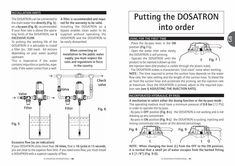
Excessive flow (as an indication)If your DOSATRON clicks more than 36 times, that is 18 cycles in 15 seconds,you are close to the superior flow limit. If you need more flow, you must installa DOSATRON with a superior capacity of flow.
The DOSATRON can be connected tothe main water line directly (Fig. 5) ;on a by-pass (Fig. 6), recommended.If your flow rate is above the opera-ting limits of the DOSATRON, see §EXCESSIVE FLOW.To prolong the working life of theDOSATRON it is advisable to installa filter (ex.: 300 mesh - 60 micronsdepending on your water quality)upstream.This is imperative if the watercontains impurities or particles, espe-cially if the water comes from a well.
A filter is recommended and requi-red for the warranty to be valid.Installing the DOSATRON on abypass enables clean water to besupplied without operating theDOSATRON and the DOSATRON tobe easily dismantled.
When connecting an installation to the public water
supply, you must respect therules and regulations in force
in the country.
Fig. 5
Checkvalve
ValveValve
Filter Filter Fig. 6
USING FOR THE FIRST TIME- Place the by-pass lever in the ONposition (Fig.7-L).- Open the water inlet valve slowly,the DOSATRON is self-priming.- Operate the DOSATRON until theproduct to be injected is drawn up intothe injection stem (the product is visible through the plastic tube).- The DOSATRON makes a characteristic “click-clack” noise when working.NOTE : The time required to prime the suction hose depends on the waterflow-rate, the ratio setting and the length of the suction hose. To bleed theair from the suction hose and accelerate the priming, set the injection rateat maximum. Once the DOSATRON is primed, adjust to the required injec-tion rate (see § ADJUSTING THE INJECTION RATE).
A mechanism to select either the dosing function or the by-pass mode : The operating medium must have a minimum pressure of 0.8 bar [12 PSI]in order to operate the by-pass.- By-pass in OFF position (Fig. 8-L) : the DOSATRON is not working and is notdrawing up any concentrate.- By-pass in ON position (Fig. 9-L) : the DOSATRON is sucking, injecting andmixing concentrate into water at the desired percentage.
NOTE : When changing the lever (L) from the OFF to the ON position,it is normal that a small jet of water escapes from the barbed fittingø 3 [1/8"] (Fig. 9-Q).
Fig. 7
Fig. 8 Fig. 9
F
L L Q
INCORPORATED HYDRAULIC BY-PASS

© DOSATRON INTERNATIONAL / 43
GB
© DOSATRON INTERNATIONAL / 42
AUTOMATIC BY-PASS
A mechanism to select either the dosing function or the by-pass mode : The operating medium must have a minimum pressure of 0.8 bar [12 PSI]in order to operate the by-pass.NOTE : When operating the By-pass through a remote control system, theoperating lever (Fig. 10-L) must be on the ON position.
AUTOMATIC BY-PASS (cont...)
Automatic anti-siphon valve : - This automatically recreates normal atmospheric pressure in the DOSATRONin the event of an accidental vacuum in the line (Fig. 11)*.Its use depends on the regulations in force in your country.- You must comply with the local water authority's requirements.- To put into operation, unscrew the nut (Fig. 11-E), remove the solid metaldisc (Fig. 11-P) and replace it by the washer (Fig. 11-C) supplied with theDOSATRON.- Screw the nut (Fig. 11-E).
Operating the automatic by-pass : - Opening of the solenoid valve.Power supply open : 1 to 2 > Normal operating : Admission of the by-pass
operating mediumBy-pass function activated : Dosing function stopped 3 > Outlet closed
Operating of the DOSATRON : - Closing of the solenoid valve. Power supply interrupted : 2 to 3 > Outlet open : Escaping of the by-pass
operating mediumActivating of the dosing function 1 > Pressure at stand-by
Fig. 10
Fig. 11
F
C
E
Ball
Rubberwasher
P
F
Q : Barbed fitting ø 3 [1/8"](supplied with the DOSATRON)
By-pass operating medium (airor water) Pressure : 0.8 to 8 bar
[12 PSI to 120 PSI]
O: 3-way Solenoid valve
(not supplied with theDOSATRON)
T : Flexible tube ø 6 x 9[1/4" ID x 3/8" OD]
*i.e. if the water outlet is lower than the inlet.

© DOSATRON INTERNATIONAL / 45
GB
© DOSATRON INTERNATIONAL / 44
Fig. 12
O-ring
CLEANING THE WATER FILTER 500 microns - 32 mesh
To remove the filter- Close the valve upstreamof the DOSATRON andallow the pressure todrop to zero.Before removing thefilter, please followthe dismantlinginstructions at §CHANGING THEMOTOR PISTON.- Remove the injectionassembly.- Unscrew the bell-housing byhand and remove it (Fig. 13). - Remove the motor piston (Fig. 14-M). - Remove the filter (Fig. 14-F). - Remove the seal (Fig. 14-N). - Clean the filter and the seal with clean water.
To refit the filter - Before re-assembly make sure that the seating area of the filter and seal (Fig.14-N) in the lower pump body and the bell-housing are clean. If necessary theseal has to be replaced.- Apply silicone grease to the thread on the body.- Then proceed in reverse order to the above.Important : in all cases tightening must be done by hand.
INTERNATIONAL CONVERSIONS
Principle : Setting at 1% ⇒ 1/100 = 1 part of concentrate for 100 parts ofwater.Ex. : Setting at 2% ⇒ 2/100 = 2 parts of concentrate for 100 parts ofwater.Ratio ⇒ 1/50.
MaintenanceRECOMMENDATIONS
1 - When using soluble products to bemade up into solutions, we recom-mend the periodic dismantling of theentire dosing part (see : § CHAN-GING SEALS IN THE INJECTIONASSEMBLY).Thoroughly rinsing all the elementsof the dosing part with water andre-assembling them after having previously lubri-cated the seal (Fig. 12) with a silicone lubricant, inthe case of difficulty in re-fitting. 2 - An air inlet, an impurity or a seal's failure caninterrupt the dosing function ; periodically checkout that the concentrate is correctly drawn up, thusincorporated into the water. 3 - Before putting the DOSATRON into operationafter a non-use period, remove the motor pistonand soak it into lukewarm water < 40° C [104° F] overnight. This helps to dissolveany deposits which may have dried onto the pistonmotor.
HOW TO DRAIN THE DOSATRON (in case of freezing temperature)
- Turn off the water supply and let the pressure drop to zero.- Remove the injection assembly.- Remove the bell and the motor piston, see § CLEANING THE WATER FILTER.- Disconnect the water inlet and outlet fittings.- Remove the lower pump body from the mounting bracket and empty anyremaining water.- The DOSATRON can now be reassembled, having first cleaned the seal(Fig.14-N next page).
Frequency: once per month depending on use.
Fig. 13
Fig. 14
M
N
F

© DOSATRON INTERNATIONAL / 47
GB
© DOSATRON INTERNATIONAL / 46
ADJUSTING THE INJECTION RATE (with pressure off) - cont...FITTING THE SUCTION TUBE
If the DOSATRON has already been used, please imperatively refer to § PRE-CAUTIONS.- Unscrew the nut (Fig. 15-E) at the bottom of the injection assembly andput it onto the tube.- Push the tube onto the barbed fitting as far as it will go and screw up thenut by hand.- For the suction tube Ø 20 (D8RV and D8R150), unscrew the nut (Fig. 16-C)at the bottom of the injection assembly and put it onto the tube.- Slide the tube onto the barb as far as it will go, tighten the clamp.
Model D8R150- Unscrew the blocking ring (Fig. 17-B). - Screw or unscrew the adjusting sleeve (Fig.17-D) so as to bring the top of the sleeveinto line with the desired injection rate.- Tighten the blocking ring (Fig. 17-B).
REMINDER: The quantity of injected productis proportional to the quantity of water ente-ring the DOSATRON. 1% ⇒ 1/100, whichmeans 100 volumes of water + 1 volume ofinjected products.
ADJUSTING THE INJECTION RATE (with pressure off)
IMPORTANT ! Use no tools.Adjustment must be made when thereis no pressure in the DOSATRON.Model D8R- Unscrew the blocking ring (Fig.17-B). - Screw or unscrew the adjusting sleeve(Fig. 17-D) so as to bring the top of thesleeve into line with the desired injectionrate.- Tighten the blocking ring (Fig. 17-B).
Fig. 15
ø 12 ø 20
D8R150D8R
ø 20(option “V”)
Fig. 16
C
E
Fig. 17
B
D
Fig. 17
B
D
CHANGING SEALS IN THE INJECTION ASSEMBLY (with pressure off)
Frequency : Once per year.IMPORTANT ! Use no tool or metallic utensils
ADVICE: Before dismantling any part of the injection assembly it is advisa-ble to operate the DOSATRON, injecting clean water so as to rinse throughthe injection system. In this way, risks of contact with concentrated solutionsin the injection assembly are minimized. During any such intervention, wearprotective eyewear and gloves !
METHOD OF REMOVING SEALFig. 18 : Between finger and thumb, pinchthe component and the seal ; push towardsone side to deform the seal.Fig. 19 : Increase the deformation to gripthe part of the seal thus exposed and pullit out of its groove. Clean the seal seatingwithout any tools. Refitting is done byhand. It is very important that the seal isnot twisted once in place as this wouldimpair its efficiency.
Fig. 18
Fig. 19

Model D8R150- Unscrew the blocking ring (Fig. 22-A).- Pull downwards to remove the suc-tion valve assembly- Thoroughly rinse all single partswith water, reassemble according tothe drawing (Fig.22-P) and checkthat the suction valve spring is in cor-rect operating condition. - Re-assemble in the reverse order tothe above by hand.
© DOSATRON INTERNATIONAL / 49
GB
© DOSATRON INTERNATIONAL / 48
CHANGING SEALS IN THE INJECTION ASSEMBLY - cont...
CLEANING AND RE-ASSEMBLING THE SUCTION VALVE SEAL
Fig. 21
Fig. 22
- Turn off the water supply and allow the pressure to drop to zero.Model D8R- Unscrew the nut (Fig. 20/21-E) and pull downwards to remove the suctiontube.- For the suction tube Ø 20 (D8RV and D8R150), loose the clamp on the suc-tion hose with a screwdriver (Fig. 21-C).- Unscrew and remove the black nut (Fig. 20/21-N). - Pull downwards to remove the suction valve assembly.- Thoroughly rinse all single parts with water, reassemble according to thedrawing (Fig.20/21-P) and check that the suction valve spring is in correctoperating condition. - Re-assemble in the reverse order to the above by hand.
N
A
N
C
P
P
P
E E
CHANGING SEALS IN THE INJECTION ASSEMBLY - cont...
CHANGING THE INJECTION SEALS- Turn off the water supply and allow the pressure to drop to zero.- Take off the suction hose, unscrew the injection part as described in theprevious chapter and pull downwards to remove it. - Change the injection stem seal (Fig. 23-O) and the plunger seal (Fig. 23-P). - For the D8R, unscrew the suction valve maintaining nut (Fig. 23-E), takingcare not to loose the single parts of the suction valve, then change the o-ring (Fig. 23-T) and the valve seal (Fig. 23-C). - For the D8R150, while holding the nut (Fig. 23-S), unscrew the sleeve (Fig.23-U) and pull downwards.- Re-assemble in the reverse order to the above.Note : The graduated scale (Fig. 23-L) must be in front of you.- Fasten the fixing ring (Fig. 23-R) firmly.
Fig. 23
D8R
option V
option V
D8R150
O
U
PPS
L
E
CT
R
Push the injec-tion assemblyas far as it will
go. Turn slightlyto the left or tothe night until
the dosing stemgets blocked.
Fig. 20
O

CHANGING THE MOTOR PISTON (with pressure off)
- Turn off the water supply and allow the pressure to drop to zero.- Remove the injection assembly as previously described. - Unscrew and remove bell-housing by hand (Fig. 24-C). - Remove the motor piston (Fig. 24-M) by pulling it up, paying particularattention to the seal (Fig. 24-J). - Change and reassemble in the reverse order to the above. - Refit the bell-housing (take care not to damage its seal) and tighten by hand.- Refit the injection part assembly.
Fig. 24
M
J
M
C C
D8R D8R150
© DOSATRON INTERNATIONAL / 51
GB
© DOSATRON INTERNATIONAL / 50
Reference Designation
REF. / Serial # : ................................................................................................................................EXAMPLE D8R BP V AF P H ii
Type of DOSATRONBP : integrated by-passV : Viscous Products(200-400 cSt)Dosing seals : AF = PH 7-14VF = PH 1-7Colour : - = Blue
P = WhiteR = RedV = GreenJ = YellowO = Orange
H = HastelloyOther extensions(consult us)
D8RVF06140745D8RVF06140745
Ref. / Serial #

THE MANUFACTURERDECLINES ALL RESPONSIBILITY IF THE DOSATRON
IS USED IN CONDITIONS THAT DO NOT CORRESPONDTO THE OPERATING INSTRUCTIONS AS INDICATED
IN THIS MANUAL
© DOSATRON INTERNATIONAL / 53
GB
© DOSATRON INTERNATIONAL / 52
TroubleshootingSYMPTOM CAUSE SOLUTION
Motor piston Piston stalled Reset piston, by hand
Maximum flow 1. Reduce flow, exceeded restart unit
2. Unscrew the bell. Takeoff the piston and checkpiston valves seals toensure correct position
The by-pass is either Place the by-pass leveron OFF position or in the ON positionhalf opened
Motor piston Return unit to youris damaged service center for repair
Filter clogged Clean the filter : p45InjectionWater flowing back Contaminated, worn, Clean or replace theminto concentrate or missing check container valve parts
No suction of The piston motor See Motor piston sectionconcentrate has stopped
Air leak (inlet) in the Check the tightness suction tube between nut and
suction hose
Blocked suction Clean or replace ittube or cloggedstrainer
Missing or worn Clean or replace itsuction check valve seal
Missing or worn Clean or replace itplunger seal
SYMPTOM CAUSE SOLUTION
InjectionNo suction of Worn injection stem Replace itconcentrate
Under injection Suction of air 1. Check the tightness ofthe nuts in the injectionarea
2. Check suction tube
Dirty or worn check Clean or replace itvalve seal
Maximum flow Reduce flowexceeded (cavitation)
Worn plunger seal Replace it
Worn injection stem Replace it
LeaksLeaks in the vicinity Injection sleeve seal Replace it or refit itof the fixing ring is damaged or correctlyunder the pump positioned incorrectlybody
Leaks between the Injection stem seal Replace it or refit itadjusting nut and damaged, positioned correctlythe blocking ring incorrectly or missing
Leaks between the Pump body seal is Unscrew the bell,body and bell damaged, positioned clean the seal seating,
incorrectly or missing replace or change the seal. Position correctly the bell.
DOSATRON doesnot start or stops

Limited warrantyDOSATRON INTERNATIONAL S.A. willprovide for replacement of all partsshown to be defective in material orworkmanship during a period of twel-ve months from the date of purchaseby the original purchaser. To obtainwarranty replacement of a part, theDOSATRON must be returned with ori-ginal proof of purchase receipt to themanufacturer or authorized distribu-tor and thereafter recognized asdefective after examination by thetechnical services of the manufactureror distributor.The DOSATRON must be flushed ofany chemical and sent to the manu-facturer or distributor prepaid, but willbe returned free of charge oncerepairs are made if found to be cove-red by the warranty.Any repairs made under warranty willnot extend the initial warranty period.This warranty only covers circumstan-ces where the part has failed due todefects caused by the manufacturingprocess. This warranty is invalid if the defectsare found to be due to the product’smisuse, inappropriate use of tools, lackof maintenance or defective installa-tion or environmental accidents orcorrosion by foreign bodies and liquidsfound within or in proximity to theDOSATRON.Before using any aggressive chemi-cals, please consult your distributor toconfirm compatibility with the dosing
pump. The seals and “o-rings” are notcovered under warranty, nor is dama-ge to the DOSATRON caused by waterimpurities such as sand.A filter (ex.: 300 mesh - 60 micronsdepending on your water quality)must be used in front of the DOSA-TRON for the warranty to be valid. DOSATRON INTERNATIONAL S.A.declines any responsibility if theDOSATRON is not used in compliancewith the operating instructions andtolerances as indicated in this owner’smanual.This warranty gives you specific legalrights and you may also have otherrights which vary from state to state.But any implied warranty or merchan-tability or fitness for a particularpurpose applicable to this product islimited in duration to the time periodof this written warranty or any impliedwarranty.The manufacturer or authorized distri-butor shall not be liable for incidentalor consequential damage, such as anyeconomic loss, resulting from breachof this written warranty or any impliedwarranty. There are no warranties,express or implied, which extendbeyond those described above, rela-ting in any way to products used inconjunction with DOSATRON INTER-NATIONAL S.A. products.Don't hesitate to call your distributoror Dosatron for any after sales service.
© DOSATRON INTERNATIONAL / 55
GB
© DOSATRON INTERNATIONAL / 54
KNOW YOUR FLOW
A SIMPLE METHODTHE DOSATRON IS COMPOSED OF:
The speed of the motor is proportional to the flow of water passing throughthe system.The greater the flow the faster it goes.In its up and down movement, you can hear the piston motor "click" :
Count the number of clicks in 30 seconds x 100 = Flow of water in litres/hour
[in 45 seconds ÷ 10 = Flow of water in GPM]
NOTE: This method of calculation cannot replace a flow meter.It is given only as an approximate guide.
A driving volumetric hydraulic pistonmotor connected to
A plunger piston
Once in the up position
Once in the down position

© DOSATRON INTERNATIONAL / 57
DE
© DOSATRON INTERNATIONAL / 56
Sie haben sich für eines der neuesten Modelle der DOSATRON Proportionaldosiererentschieden. Wir gratulieren Ihnen zu dieser Wahl. Dieser Apparat ist das Ergebniseiner langjährigen Erfahrung. Durch die Arbeit unserer Ingenieure gehört derDosatron nunmehr zu den Spitzenprodukten im Bereich der Proportionaldosierungohne Elektrizität. Die Wahl der für die Fabrikation notwendigen Materialien unter-lag grösster Sorgfalt, damit eine Resistenz gegenüber allen bzw. den meisten aufdem Markt erhältlichen Chemikalien gesichert werden konnte. Dieser DOSATRONwird sich im Laufe der Zeit als treuester Verbündeter zeigen. Einige regelmässigePflegemassnahmen werden Ihnen eine Betriebstüchtigkeit garantieren, wobei dasWort Panne fehl am Platze sein wird.
WIR BITTEN DAHER UM AUFMERKSAMES LESEN DIESER ANLEITUNG, BEVOR DAS GERÄT
IN BETRIEB GENOMMEN WIRD.
Dieses Dokument stellt keine vertragliche Verpflichtung dar und dient nurzur Information. DOSATRON INTERNATIONAL behält sich das Recht vor,jederzeit eine Änderung seiner Geräte vorzunehmen.
©DOSATRON INTERNATIONAL S.A. 2007
Wichtig ! Die Seriennummer des Dosierers befindet sich auf demPumpenkörper. Wir bitten Sie, diese Nummer in denunten aufgeführten Teil einzutragen und sie bei jeglicherKontaktaufnahme oder Informationsaustausch mit IhremHändler bereit zu haben.
Ref. : ................................................................................
Seriennr. : ........................................................................
Kaufdatum : ....................................................................
Deutsch

© DOSATRON INTERNATIONAL / 59
DE
© DOSATRON INTERNATIONAL / 58
INSTALLATION SEITE
Vorsichtsmassnahmen ........................................................................61
Installation des Dosatron ..................................................................63
Hinweise zur Installation ..................................................................65
INBETRIEBNAHME
Erstinbetriebnahme ............................................................................67
Eingebauter Hydraulischer Bypass ................................................67
Ferngesteuerter Bypass ......................................................................68
WARTUNG
Wichtige Hinweise................................................................................70
Entleeren des Dosatron ......................................................................70
Reinigung des eingebauten Filters ................................................71
Umrechnung % -Verhältnis ..............................................................71
Anschluss des Saugschlauches ........................................................72
Einstellen der Dosierung....................................................................72
Auswechseln der Dichtungen des Dosierteils ............................73
Auswechseln des Motorkolbens ......................................................76
DIE ARTIKELBEZEICHNUNG ..........................................................77
MÖGLICHE BETRIEBSSTÖRUNGEN ............................................78
GARANTIE ..............................................................................................80
InhaltsverzeichnisTECHNISCHE MERKMALE
Betriebswasserdurchsatz: 500 l/h mini - 8 m3 maxi [2.2 Fl oz/min - 40 US GPM]
Betriebswasserdruck: barPSI
Dosierung (aussen einstellbar): %Verhältnis
Menge des eingespritzten Produkts: Mini l/h - Maxi l/hUS Fl. oz/minUS GPM/max
Maximale Betriebstemperatur: 40 °C [104 ° F]
Anschluß (NPT/BSP Aussengewinde) : Ø 40x49 mm [1” 1/2 M]
Zylinderkapazität des hydraulischen Antriebs (bei jedem zweiten Kolbenschlag): ca. 1.6 l [0.4224 US Gallons]
PAKETINHALT: 1 DOSATRON / 1 Wandhalterung / 1 durchsichtigerSaugschlauch / 1 Saugfilter / 1 Betriebs- und Wartungsanleitung
ACHTUNG ! Der DOSATRON ist nicht voreingestellt, s. Paragraph EINSTELLUNG DER DOSIERUNG
0.15 - 82 - 110
0.2 - 21:500 - 1:50
1 - 1600.560.70
D 8 R
ABMESSUNGEN
Durchmesser: cm ["]
Gesamthöhe: cm ["]
Breite insgesamt: cm ["]
Gewicht: ± kg [lbs]
Paketmasse: cm["]
Gewicht des Pakets: ± kg [lbs]
18.4 [7 1/4]
59.1 [23 1/4]
31 [12 1/4]
4 [8.8]
0.15 - 82 - 110
1 - 51:100 - 1:20
5 - 4002.8
1.76
D 8 R 150
18.4 [7 1/4]
66.7 [26 1/4]
31 [12 1/4]
4.5 [10]
60 x 36.5 x 24[23 2/3 x 14 1/3 x 9 1/2]
82 x 26 x 21[32 1/4 x 10 1/4 x 8 1/4]
5.5 [12.15] 7 [15.5]

© DOSATRON INTERNATIONAL / 61
DE
InstallationVORSICHTSMASSNAHMEN
1 - ALLGEMEINES - Wenn man eine Anlage sei es andie öffentliche, sei es an die eigeneWasserversorgung anschliesst, somüssen unbedingt die Normen zumSchutz und zur Trennung desWasserzuflusses berücksichtigtwerden. DOSATRON empfiehlthierfür einen Systemtrenner. - Wenn die Anlage höher gelegen istals der DOSATRON, könnte even-tuell Wasser in den DOSATRONzurücklaufen ; daher wird empfoh-len, hinter dem Gerät einRückschlagventil einzubauen. - Den DOSATRON nicht über einemBehälter mit Säure oder aggressivenMitteln anbringen und ihn vorDämpfen, die eventuell von diesenMitteln aufsteigen, schützen. - Den DOSATRON von Wärmequellenentfernt halten und im Winter vorFrost schützen. - Den DOSATRON nicht an dieAnsaugleitung der Arbeitspumpeanschließen (Siphoneffekt). - Bei jeder Handhabung des DOSA-TRON Schutzbrille und-handschuhetragen.
- Um die Dosierpräzision zu gewähr-leisten, muss der jährliche Austauschder Dichtungen des Dosierteils erfol-gen. Dieser steht unter der alleinigenVerantwortung des Benutzers. - Die Einstellung des Dosatron erfolgtunter alleiniger Verantwortung sei-nes Benutzers. Letzterer ist dazuverpflichtet, die Anweisungen desChemikalienherstellers strengstenszu befolgen.- Stellen Sie sicher, dass derWasserdurchsatz und - druck derInstallation den Betriebswerten desDOSATRONS entspricht. - Der Benutzer allein ist verantwort-lich für die korrekte Wahl derEinstellungen des DOSATRONS, zumErhalt der gewünschlen Dosierung. - Lufteintritt, Unreinheiten oder einzerrissener Ring können das richtigeDosieren unterbrechen. Es ist zuempfehlen, regelmässig zu überprü-fen, ob das konzentrierte Produktvom DOSATRON angesaugt wird.- Wechseln Sie den Ansaugschlauchdes DOSATRONS sobald dieser durchdas Konzentrat beschädigt erscheint. - Am Ende jeder Benutzung dasSystem drucklos lassen (Empfehlung).
© DOSATRON INTERNATIONAL / 60
Präzise, einfach und zuverlässig
Motorkolben
Klares Wasser
Lösung Wasser + % Produkt
Dosierkolben
Einstellen der Dosierung (%)
Zu dosierendes Konzentrat
Der DOSATRON funktioniert ohne Strom und wird einfach an dieWasserleitung angeschlossen. Dabei wirkt der Wasserdruck alsAntriebskraft. Auf diese Weise wird das Konzentrat angesaugt,der gewünschte Prozentsatz dosiert und in der Mischkammer mitdem Antriebswassser homogenisiert. Die so hergestellte Lösungwird dann in die Wasserleitung befördert. Die Menge des ein-gespritzten Produkts ist immer proportional zumWasservolumen, dasdurch den DOSATRONfliesst, auch bei even-tuellen Durchsatz - undDruckschwankungen.

© DOSATRON INTERNATIONAL / 63
DE
© DOSATRON INTERNATIONAL / 62
1 - ALLGEMEINES (Forsetzung)- Das Durchspülen des DOSATRONSist unbedingt notwendig : . bei jedem Produktwechsel, . vor jeder Handhabung, um jeglichenKontakt mit dem aggressiven Produktzu vermeiden. - Vor Inbetriebnahme mit aggressi-ven Produkten bitte Händler nachVerträglichkeit fragen.- Jede Montage oder jeglichesFestziehen darf nur von Hand undohne Werkzeug erfolgen.
2 - VERUNREINIGTES WASSER - Bei Wasser mit Verunreinigungenmuß unbedingt vor der Dosierpumpeein Filter eingebaut werden (z. B. : 300mesh - 60 microns je nachWasserqualität). Ohne Filter kann einvorzeitiger Verschleiss des DOSATRONdurch abrasive Partikel erfolgen.
3 - DRUCKSTÖSSE / ZU HOHER DURCHSATZ - Bei Anlagen, die Druckstössen aus-gesetzt sind, muss ein Gerät zurVerhinderung von Wasserschlag ein-gebaut werden (ReguliersystemDruck/Durchsatz).- Bei automatisierten Anlagenwird die Verwendung eines lang-sam öffnenden und schliessendenMagnetventils empfohlen.- In einer Anlage, in der der DOSA-TRON mehrere Sektoren versorgt,
soll das Schliessen eines Sektors unddas Öffnen eines anderen Sektorsgleichzeitig erfolgen (simultaneAktivierung der Magnetventile).
4 - INSTALLATIONSORT - Der DOSATRON und das Konzentratmüssen zugänglich sein. IhreInstallation darf auf keinen Fall einUmweltverschmutzungs - oderKontaminationsrisiko darstellen. - Eswird empfohlen, alle Wasserleitungenmit einer Markierung, dass das WasserZusatzmittel enthält, und mit folgen-dem Hinweis zu versehen : "ACHTUNG ! Kein Trinkwasser".
5 - WARTUNG - Nach dem Gebrauch alle Teile desDOSATRONS durch Ansaugen von kla-rem Wasser durchspülen (~ 1/4 Liter[8 1/2 US Fl.oz]). - Eine jährliche Wartung optimisiert dieLanglebigkeit Ihres DOSATRON. DasAuswechseln der Dosierdichtungensollte mindestens einmal jährlich erfol-gen, je nach Einsatzbedingungen.
6 - SERVICE - Dieser DOSATRON wurde vorVersand getestet. - Austauschteile und Dichtungsbeutelsind verfügbar. - Rufen Sie Ihren Händler oderDOSATRON für jeglichen Wartungs-service an.
VORSICHTSMASSNAHMEN (Fortsetzung)
DIE MONTAGE MUSS OHNEWERKZEUGE ERFOLGENDer DOSATRON wird mit folgendenTeilen geliefert :- eine Wandhalterung,- ein Saugschlauch mit Saugfilter.- 1 Schlauch (Bypass) ø 6 x 9 [1/4"ID x 3/8" OD]Der Halter dient zur Befestigung aneiner Wand. - Die Zapfen des DOSATRON (Abb.1-A) in die Wandhalterung einfüh-ren (Abb. 1-S).
- Die Anschlüsse (Abb. 1-E) und dieKlemmringe (Abb. 1-C) von denWasserein-und-auslassöffnungendes DOSATRON entfernen.- Die vorhandenen Schutzkappen(Abb. 1-B) abnehmen, bevor Sie dasGerät an die Wasserversorgunganschließen. - Darauf achten, dass die Dichtungenam Einlass und Auslass korrekt sit-zen. Zuerst den O-Ring (Abb. 1-J),dann den Ring (Abb. 1-G) auflegen.- Stellen Sie sicher, daß das Wasser indie Richtung fließt, in die die Pfeileauf dem Gerät zeigen.
INSTALLATION DES DOSATRON
A
Abb. 1E C B G J
B
S

© DOSATRON INTERNATIONAL / 65© DOSATRON INTERNATIONAL / 64
DE
Bei Anschluss mit PVC-Rohr ist wiefolgt zu verfahren: - Verfahren Sie genauso wie beimAnschluß mit Polyethylen- oderPropylenrohr. Vor dem Anziehenjedoch die für den Klemmring vorge-sehene Stelle mit PVC-Kleberbestreichen.- Den Klemmring in seine korrekteLage bringen. Dazu den Schlitz(Abb. 2-C) mit beiden Daumen auf-ziehen, damit der Kleber nichtabgeschabt wird. Anschliessend dieAnschlüsse anziehen.- Die Anschlüsse anziehen.
HINWEIS: Eine Stunde warten, bevordie Anlage unter Druck gesetzt wird.Für den Fall, daß die Anlage später
einmal demontiert wird, sollteman wissen, daß der PVC-Klebernicht an dem Polyacetal-Klemmring haftet.
Das Gerät kann anhand eines Schlauches mit einem Innendurchmesser von40 Millimetern und anhand von Rohrschellen und drehbarenAnschlußstutzen ø 40 x 49 mm [1"1/2] an die Wasserversorgung ange-schlossen werden. Stellen Sie sicher, daß das Wasser in die Richtung, in diedie Pfeile auf dem Gerät zeigen, fliesst. Der DOSATRON wird mit einem Ansaugschlauch geliefert (kann beliebiggekürzt werden) der eine Benutzung von Behältern mit grosser Kapazitätermöglicht. Dieser Schlauch muß unbedingt mit einem Saugfilter und einemBallast versehen sein. Für den Anschluss dieses Schlauchs siehe das ent-sprechende Kapitel.
INSTALLATION DES DOSATRON (Fortsetzung)
Bei Anschluss mit Polyethylen -und Polypropylenrohr ist wie folgtzu verfahren: - Die Anschlüsse (Abb. 2-E) und dieKlemmringe (Abb. 2-C), auf dassauber abgeschnittene und abge-schrägte Rohr stecken (Einlass undAuslass).- Das Rohr bis zum Anschlag in dieWasserein - und auslassöffnungeneinführen (Abb. 2).- Die Klemmringe beidseitig jeweilsbis zum Anschlag schieben (Abb.2-C).- Die Anschlüsse anziehen (Abb. 2-E).
E
Abb. 2
C
ACHTUNG ! - Den Saugkopf ungefähr 10 cm [4”] vom Boden desLösungsbehälters entfernt lassen, damit keine nichtlöslichen Teilchen,die den Dosierkörper beschädigen könnten, angesaugt werden (Abb. 3).- Den Saugkopf nicht auf den Boden legen.
ANMERKUNG: Die maximale Ansaughöhe beträgt 4 m [13 ft].
- Schließen Sie den mit dem Saugfilter versehenen Schlauch an und tauchenSie ihn in die zu dosierende Lösung ein.
In keinem Fall darf sich das Niveau der zu dosierenden Lösung höher alsder Einlass des Dosatron befinden, um einen Siphon-Effekt zu vermeiden.
INSTALLATION DES DOSATRON (Fortsetzung)
10 c
m
Abb. 3
WIE SIE ES NICHT MACHEN SOLLEN
WIE SIE ES MACHEN SOLLEN
▼
▼
Abb. 4

© DOSATRON INTERNATIONAL / 67
DE
© DOSATRON INTERNATIONAL / 66
HINWEISE ZUR INSTALLATION
Zu hoher Durchsatz (Orientierungshilfe)Wenn Ihr DOSATRON mehr als 36 Kolbenschläge, d.h. 18 Zyklen in 15Sekunden macht, dann ist der DURCHSATZ ZU HOCH. Sie sollten einenDOSATRON mit höherer Wasserdurchsatzkapazität wählen.
Die Installation kann je nach denErfordernissen Ihrer Anlage direkt andie Wasserleitung (Abb. 5), oder aneine Bypass Leitung (Abb. 6) erfol-gen. Falls der Durchsatz die Grenzendes DOSATRON übersteigt, siehe§ ZU HOHER DURCHSATZ. Um die Langlebigkeit des DOSA-TRONS zu gewähren, wird dazugeraten, einen Filter (z. B. : 300 mesh -60 microns je nach Wasserqualität)vor diesem zu installieren.Diese Massnahme ist unumgänglich,wenn das Wasser Schmutzpartikeloder Unreinheiten aufweist, insbeson-
dere wenn das Wasser aus einemBrunnen oder einer Bohrung stammt. Der Filter ist unbedingt notwendig,damit die Garantie gültig ist. Die Montage eines Bypasses erlaubtden Zufluss von klarem Wasser, ohnedass der DOSATRON funktioniert unddessen problemlosen Ausbau.
Bei Installation ansTrinkwassersystem beachten
Sie bitte die Normen undAuflagen jedes Landes.
Rückschlagventil
Ventil Ventil
Filter Filter
Abb. 6Abb. 5
Inbetriebnahme des DOSATRON
ERSTINBETRIEBNAHME - Den Bypass-Schalter auf die StellungON bringen (Abb. 7-L).- Die Wasserzufuhr nach und nach öffnen. - Den Apparat solange funktionierenlassen, bis das Konzentrat dieDosierpartie erreicht hat (sichtbar amtransparenten Ansaugschlauch).- Beim Betrieb gibt der DOSATRON ein charakeristrisches Klicken von sich. ANMERKUNG: Die Ansaugzeit für das Konzentrat hängt vom Durchsatz,der Einstellung der Dosierung und der Länge des Ansaugschlauches ab. ZurBeschleunigung des Ansaugvorgangs die maximale Dosierung einstellen.Bei Erreichen der Dosierpartie den gewünschten Wert einstellen (siehe §EINSTELLEN DER DOSIERUNG).
Ein - und Ausschalten der Produktansaugung: Für den einwandfreien Betrieb des Bypasses muß das Antriebswasser einenMindestdruck von 0.8 Bar haben. - Bypass auf ON (Abb. 8-L), der DOSATRON funktioniert : Ansaugen, Einspritzenund Mischen von Konzentrat und Wasser zum gewünschten Prozentsatz. - Bypass auf OFF (Abb. 9-L), der DOSATRON funktioniert nicht : Der Motor stehtstill und es wird kein Konzentrat angesaugt.
ACHTUNG ! Wenn der Schalter L von der Stellung OFF auf die StellungON gebracht wird, entweicht eine kleine Menge Wasser aus dem geriffel-ten Zapfen (Abb. 9-Q). Das ist ganz normal.
Fig. 7
Fig. 8 Fig. 9
F
L L Q
EINGEBAUTER HYDRAULISCHER BYPASS
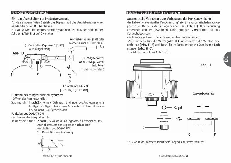
© DOSATRON INTERNATIONAL / 69
DE
© DOSATRON INTERNATIONAL / 68
FERNGESTEUERTER BYPASS
Ein - und Ausschalten der Produktansaugung: Für den einwandfreien Betrieb des Bypass muß das Antriebswasser einenMindestdruck von 0.8 bar haben.HINWEIS: Wird der ferngesteuerte Bypass benutzt, muß der Handbetrieb-Schalter (Abb. 8-L) auf ON stehen.
Funktion des ferngesteuerten Bypasses: - Öffnen des Magnetventils. Stromzufuhr: 1 nach 2 > normaler Gebrauch: Eindringen des Antriebsmediums
des Bypasses. Bypass-Funktion = Abschalten der Dosierfunktion3 > Wasserauslauf geschlossen
Funktion des DOSATRON: - Schliessen des Magnetventils. Keine Stromzufuhr: 2 nach 3 > Wasserauslauf geöffnet: Entweichen des
Antriebswassers des Bypasses nach aussenAnschalten des DOSATRON1 > Keine Druckveränderung
Abb. 10
F F
1Q : Geriffelter Zapfen ø 3 [1/8"]
(wird mitgeliefert)
Antriebsmedium (Luft oderWasser) Druck : 0.8 Bar bis 8
Bar
O : Magnetventil oder 3-Wege-Ventil
in L-Form(nicht mitgeliefert)
T : Schlauch ø 6 x 9[1/4" ID] x [3/8" OD]
FERNGESTEUERTER BYPASS (Fortsetzung)
Automatische Vorrichtung zur Vorbeugung der Hohlsaugwirkung: - Im Falle einer eventuellen Drucksenkung* stellt sie automatisch den atmos-phärischen Druck in der Anlage wieder her (Abb. 11). Ihre Benutzungunterliegt den im jeweiligen Land gültigen Vorschriften für dasGesundheitswesen.- Richten Sie sich nach den entsprechenden Bestimmungen.- Zur Inbetriebnahme die Mutter (Abb. 11-E) abschrauben, die Metallscheibeentfernen (Abb. 11-P) und durch die im Paket enthaltene Scheibe mit Lochersetzen (Abb. 11-C).- Die Mutter anziehen (Abb. 11-E).
Abb. 11
C
E
Kugel
Gummischeibe
P
*Z.B. wenn der Wasserauslauf tiefer liegt als der Wassereinlass.
2
3

DE
© DOSATRON INTERNATIONAL / 71© DOSATRON INTERNATIONAL / 70
Abb. 12
Dichtung
WartungWICHTIGE HINWEISE
1 - Wenn Sie lösliche Mittel zurHerstellung lhrer Lösung verwenden,so wird empfohlen, das ganzeDosierteil regelmäßig abzubauen(siehe § AUSWECHSELN DICHTUN-GEN DES DOSIERTEILS), dieElemente mit reichlich klarem Wasserzu spülen und nach vorherigemEinfetten der Dichtung wieder zusammenzumon-tieren (Abb. 12). 2 - Das Eindringen von Luft und Verunreinigungenoder eine beschädigte Dichtung können eineUnterbrechung des Dosiervorgangs bewirken.Prüfen Sie regelmäßig nach, ob die Lösung richtigverbraucht wurde.3 - Vor Inbetriebnahme des DOSATRON (nach län-gerer Nichtbenutzung) den Motorkolben einigeStunden lang in lauwarmes (< 40° C) Wasserlegen. So werden trockene Ablagerungen imMotorkolben entfernt.
ENTLEEREN DES DOSATRON (Bei Ausbau wegen Frostgefahr)
- Wasserzufuhr schließen. - Das Dosierteil abnehmen.- Die Glocke und den Motor entnehmen, siehe § REINIGUNG DES EINGE-BAUTEN FILTERS.- Die Anschlußstutzen von Wassereinlaß und Wasserauslaß lösen. - Den Pumpenkörper von der Wandhalterung nehmen und entleeren. - Vor dem Zusammenbau die Dichtung (Abb. 14-N) reinigen.
REINIGUNG DES EINGEBAUTEN FILTERS 500 µ - Maschenweite 32
Ausbau des Filters- Wassereinlass schliessenund Druck abfallen lassen.Um den Filter zuerreichen, folgen Sieden Anleitungen fürden Auseinanderbauwie auf den Seiten§ AUSWECHSELNDES MOTORKOLBENS.- Die Dosierpartie abbauen.- Die Glocke von Hand los-schrauben und abnehmen(Abb. 13).- Den Motorkolben herausneh-men (Abb. 14-M).- Den Filter herausnehmen (Abb. 14-F).- Die Dichtung lösen (Abb. 14-N).- Den Filter und die Dichtung mit klarem Wasserreinigen.
Wiedereinbau des Filters- Vor dem Wiedereinbau sicherstellen, dass die Auflageflächen des Filters undder Dichtung (Abb. 14-N) am Dosierkörper und an der Glocke sauber sind.Wenn nötig, die Dichtung auswechseln.Das Gewinde des Pumpengehäuses schmieren (Silikonfett).- In der umgekehrten Reihenfolge des Ausbaus vorgehen.Wichtig: das Festschrauben muss unbedingt von Hand erfolgen
UMRECHNUNG % -VERHÄLTNIS
Prinzip : Einstellung 1% ⇒ 1/100 = 1 Volumen des konzentriertenProdukts plus 100 Wasservolumen. Beispiel : Einstellung 2% ⇒ 2/100 = 2 Volumen des konzentriertenProdukts plus 100 Wasservolumen. Verhältnis ⇒ 1/50.
Wie oft : Einmal im Monat, je nach Gebrauch.
Abb. 13
Abb. 14
M
N
F

© DOSATRON INTERNATIONAL / 73
DE
© DOSATRON INTERNATIONAL / 72
ANSCHLUSS DES SAUGSCHLAUCHES
Falls Sie den Anschluss mit einem DOSATRON vornehmen, der schon benutztwurde, lesen Sie bitte § VORSICHTSMASSNAHMEN.- Zum Anschliessen des Ansaugschlauches die Mutter (Abb. 15-E), die sichunten am Dosierteil befindet, losschrauben und über den Saugschlauch stülpen.- Den Schlauch über das gerillte Ansatzstück ganz nach oben drücken unddie Mutter von Hand festziehen. - Beim Ansaugschlauch Ø 20 (D8RV und D8R150) die auf dem Schlauchbefindliche (Fig. 16-C) Klemme mit einem Schraubenzieher lösen. - Stülpen Sie den Ansaugschlauch soweit es geht auf das geriffelteAnsatzstück, und ziehen Sie die Schelle wieder fest.
EINSTELLEN DER DOSIERUNG (druckfrei)
ACHTUNG ! Keine Werkzeuge benutzen.Die Einstellung der Dosierung darfnicht unter Druck erfolgen, d.h. erstnach Schliessen der Wasserzufuhr.Modelle D8R- Den Blockierring losschrauben (Abb. 17-B). - Die Einstellmutter nach oben oder nachunten schrauben (Abb. 17-D), bis der obereTeil der Mutter auf der gewünschtenEinstellmarkierung steht.- Den Blockierring wieder festschrauben(Abb. 17-B).
Abb. 15
ø 12 ø 20
D8R150D8R
ø 20(Option “V”)
Abb. 16
C
E
Abb. 17
B
D
EINSTELLEN DER DOSIERUNG (Fortsetzung)
Modelle D8R150- Den Blockierring losschrauben (Fig. 17-B). - Die Einstellmutter nach unten oder nachoben festschrauben (Abb. 17-D), bis derobere Teil der Mutter auf der gewünschtenEinstellmarkierung steht.- Den Blockierring wieder festschrauben(Abb. 17-B).
MERKE: Die Menge des eingespritztenProdukts ist proportional zur Wassermenge,die den Dosatron durchfliesst. 1% ⇒1/100, d.h. 100 Volumen Wasser + 1Volumen Produkt.
Abb. 17
B
D
AUSWECHSELN DER DICHTUNGEN DES DOSIERTEILS (druckfrei)
Wie oft : Einmal pro Jahr.ACHTUNG ! Kein Werkzeug oder metallene Gegenstände benutzen Es wird geraten, vor jeglichem Ausbau der Dosierpartie den DOSATRON zubetätigen und klares Wasser anzusaugen, um die Ansaugpartie durchzuspü-len. Dies vermeidet jeglichen Kontakt mit noch in der Dosierpartiebefindlichen Chemikalien. Bei jeglichem Eingriff dieser Art Schutzbrille und- handschuhe tragen. METHODE ZUR ENTFERNUNG EINER DICHTUNG Abb. 18: Die Dichtung und das Teil zwischenDaumen und Zeigefinger klemmen; dieDichtung auf die gegenüberliegende Seitedrücken, um sie zu verformen. Abb. 19: Die Verformung verstärken, um dieDichtung am herausragenden Teil zu erfassenund sie dann aus ihrer Fassung entnehmen.
Mit einem Tuch die Dichtung reinigen. Der Zusammenbau erfolgt von Hand.Es ist sehr wichtig, dass dabei die Dichtungnicht verdreht wird, da sonst keineAbdichtung mehr garantiert ist.
Abb. 18
Abb. 19

Abb. 23D8R
Option V
Option V
D8R150
O
U
PPS
L
E
CT
R
Die Dosierpartiebis zum Anschlageinführen. Leichtnach rechts oderlinks drehen, bisder Dosierkörperblockiert bleibt.
O
© DOSATRON INTERNATIONAL / 75
DE
© DOSATRON INTERNATIONAL / 74
AUSWECHSELN DER DICHTUNGEN DES DOSIERTEILS (Fortsetzung)
REINIGUNG UND WIEDEREINBAU DES ANSAUGVENTILS
Abb. 21
Abb. 22
- Wasserzufuhr schliessen und somit Dosierer druckfrei machen.Modelle D8R- Die Haltemutter losschrauben (Abb. 20/21-E) und Saugschlauch abnehmen.- Beim Ansaugshlauch Ø 20 (Option V) die auf dem Schlauch befindliche(Fig. 21-C) Klemme mit einem Schraubenzieher lösen. - Die Mutter (Abb. 20/21-N) losschrauben und abnehmen. - Nach unten ziehen und das ganze Saugventil entnehmen. - Die Einzelteile gut abspülen, sie nach Schema wieder zusammenbauen(Fig.20/21-P) und dabei prüfen, ob die Feder korrekt arbeitet. - Der erneute Zusammenbau erfolgt per Hand in umgekehrter Reihenfolgedes Auseinanderbaus.
Modelle D8R150- Die kegelförmige Blockiermutter los-schrauben (Abb. 22-A).- Nach unten ziehen und das ganzeSaugventil entnehmen. - Die Einzelteile gut abspülen, sie nachSchema wieder zusammenbauen(Fig.22-P) und dabei prüfen, ob dieFeder korrekt arbeitet. - Der erneute Zusammenbau erfolgt perHand in umgekehrter Reihenfolge desAuseinanderbaus.
N
A
N
C
P
P
P
E E
AUSWECHSELN DER DICHTUNGEN DES DOSIERTEILS (Fortsetzung)
DOSIERDICHTUNGEN- Wasserzufuhr schliessen und somit Dosierer druckfrei machen.- Ansaugschlauch abmontieren, Abschrauben der Dosierpartie wie im vorange-gangenen Kapitel beschrieben, und sie durch Ziehen nach unten abnehmen. - Austauschen der Dosierkörperdichtung (Fig. 23-O) und der Saugkolben-dichtung (Fig. 23-P). - Beim Modell D8R den Haltering des Saugventils (Fig. 23-E) abschrauben. Dabeidarauf achten, keine Einzelteile des Saugventils zu verlieren. Austauschen der O-Ring- Dichtung (Fig. 23-T) und der Saugventildichtung (Fig. 23-C). - Beim Modell D8R150 muss die Verschraubung (Fig. 23-S) festgehaltenwerden und gleichzeitig der Dosierkörper (Fig. 23-U) abgeschraubt und zurAbnahme nach unten gezogen werden.- Der erneute Zusammenbau erfolgt in umgekehrter Reihenfolge desAuseinanderbaus.Anmerkung: Die Dosierskala (Fig. 23-L) muss so positioniert werden, dass siesich vor Ihnen befindet. Den Haltering (Fig. 23-R) bis zum Anschlag festziehen.
Abb. 20

© DOSATRON INTERNATIONAL / 77
DE
© DOSATRON INTERNATIONAL / 76
Die Artikelbezeichnung
REF. / Seriennummer: ....................................................................................................................BEISPIEL D8R BP V AF P H ii
DOSATRON TypBP: Integrierter BypassV: Option viskose Produkte(200-400 cSt)Dosierdichtungen: AF = PH 7-14VF = PH 1-7Farbe : - = Blau
P = WeissR = RotV = GrünJ = GelbO = Orange
H = HastelloyAndere Buchstaben(bitte angeben)
D8RVF06140745D8RVF06140745
REF. / Seriennummer
AUSWECHSELN DES MOTORKOLBENS (druckfrei)
- Wasserzufuhr schliessen und somit Dosierer druckfrei machen.- Abbau der Dosierpartie wie im vorangegangenen Kapitel beschrieben. - Die Glocke von Hand losschrauben (Abb. 24-C) und abnehmen.- Den gesamten Motorkolben (Abb. 24-M) nach oben herausziehen, dabeibesonders auf die Saugkolbendichtung (Fig. 24-J) achten. - Auswechseln und erneuter Zusammenbau per Hand in umgekehrterReihenfolge des Auseinanderbaus. - Die Glocke wieder per Hand aufschrauben und dabei darauf achten, dassdie Dichtung nicht beschädigt wird.- Die Dosierpartie erneut anbringen.
Abb. 24
M
J
M
C C
D8R D8R150

© DOSATRON INTERNATIONAL / 79
DE
© DOSATRON INTERNATIONAL / 78
Mögliche BetriebsstörungenSTÖRUNGEN URSACHEN ABHILFE
MotorkolbenMotorkolben Den Kolben per Handblockiert erneut in Gang bringen
Zu hoher Durchsatz 1. Durchsatz drosseln,wieder starten
2. Überprüfen, ob dieDichtungen der Motor-ventile richtig sitzen
Der Bypass ist entweder Stellen Sie den Schalterganz oder halb geöffnet auf ON
Kolben defekt DOSATRON an Händler zurücksenden
Filter verstopft Reinigen des Filters: s.71Dosierung Rückfluss des Saugventil oder Saugventil reinigenKonzentrats in den Saugventildichtung oder wechselnKonzentrats - verschmutzt, abgenutzt behälter oder nicht vorhanden
Der Motorkolben stoppt Siehe MotorkolbenLufteintritt am Saugschlauch und Festsit-Saugschlauch zen der Muttern überprüfen
Saugschlauch verstopft Teile reinigenoder Saugfilter verklebt oder austauschen
Saugventildichtung Dichtung reinigenabgenutzt, falsch oder austauschenmontiert oder verschmutzt
Saugkolbendichtung Dichtung reinigenfalsch montiert, oder austauschenverschmutzt oder aufgequollen
STÖRUNGEN URSACHEN ABHILFE
Dosierung Konzentrat wird Kratzer am Dosierkörper austauschennicht angesaugt Dosierkörper
Unterdosierung Lufteintritt 1. Prüfen, ob Muttern desDosierteils gut festge-schraubt sind
2. Zustand des Saug-schlauchs überprüfen
Dichtung des Reinigen oderSaugventils abgenutzt Ersetzen der Dichtungoder verschmutzt
Zu hoher Durchsatz Durchsatz reduzieren
Saugkolbendichtung Dichtung ersetzenabgenutzt
Kratzer am Dosierkörper ersetzenDosierkörper
LeckstellenLeckstellen an Dosierzylinderdichtung Auswechseln oder Mutter unterhalb abgenutzt, schlecht korrektes Einsetzen des Pumpenkörpers montiert oder nicht der Dichtung
vorhanden
Leckstelle zwischen Dosierkörperdichtung Auswechseln oder Einstellschraube verschlissen, schlecht korrektes Einsetzenund montiert oder nicht der DichtungBlockierungsring vorhanden
Leckstellen zwischen Dichtung beschädigt, Dichtung korrekt einsetzenPumpenkörper und schlecht montiert oder Dichtungssitz reinigen oderGlocke nicht vorhanden Dichtung austauschen
DOSATRON INTERNATIONAL LEHNT JEGLICHE VERANTWORTUNG BEI NICHTBEACHTUNG DER
GEBRAUCHSANWEISUNG DES GERÄTES AB.
Ihr DOSATRONstartet nichtoder stoppt
Konzentrat wirdnicht angesaugt

© DOSATRON INTERNATIONAL / 81
DE
© DOSATRON INTERNATIONAL / 80
GarantieDOSATRON INTERNATIONAL S.A. verp-flichtet sich, jegliches Teil zu ersetzen,dessen Fabrikationsfehler nachgewiesenwerden kann, und dies für einenZeitraum von 12 Monaten abEinkaufsdatum (Ersteinkauf am Werk).
Um Garantieersatz zu erhalten, muss dasGerät oder das Teil mit dem ur-sprüngli-chen Einkaufsbeweis an den Herstelleroder Händler zurückge-schickt werden.Die Fehlerhaftigkeit wird erst nach Über-prüfung durch die Technische Abteilungdes Herstellers oder Händlers bestätigt.
Das Gerät muss von chemischenProdukten gereinigt sein und demHersteller oder Händler franko zuge-schickt werden. Es wird nur dannkostenlos zurückgeschickt, wenn dieReparatur unter Garantie läuft.
Die unter Garantie vorgenommenenEingriffe verlängern den Garantiezeit-raum nicht weiter.
Diese Garantie gilt nur für Fabrikation-sfehler.
Die Garantie gilt nicht für Defekte, dieauf eine anormale Installation desGeräts zurückzuführen sind oder durchVerwendung von unangemessenenenWerkzeugen, Wartungs oder Installa-
tionsfehler, einen Unfall oder Korrosiondurch Fremdkörper oder Flüssigkeiten imInnern des Geräts oder dessen Umfeldverursacht worden sind.
Vor Inbetriebnahme mit aggressivenProdukten bitte Händler nachVerträglichkeit fragen.
Die Garantie gilt weder für Dichtungen(Verschleissteile) noch für durchUnreinheiten im Wasser (wie z. B. Sand)verursachte Defekte.
Ein Filter (z. B. : 300 mesh - 60 micronsoder weniger) muss vor dem Apparat ins-talliert sein, um diese Garantie gelten zumachen.
DOSATRON INTERNATIONAL S.A. haf-tet nicht für Geräte, sollten dieVorschriften und Funktionswerte der vor-liegenden Gebrauchsanweisung beimBetrieb der Geräte nicht beachtet wor-den sein.
Eine explizite oder implizite Garantie giltnicht in Bezug auf andere Produkte oderZubehör, die zusammen mit dem DOSA-TRON benutzt werden.
Für Beratung und Kundendienst neh-men Sie bitte Kontakt mit IhremVertriebspartner oder Dosatron auf.
BESTIMMUNG DES DURCHSATZES
EINE EINFACHE METHODEDER DOSATRON BESTEHT AUS:
Die Motorgeschwindigkeit ist abhängig vom Wasserdurchsatz im Gerät.
Bei der Hin-und Herbewegung des Kolbens ist ein klopfendes Geräusch hörbar.
Zählen Sie die Anzahl des Klopfgeräuschs in 30 Sekunden x 100= Wasserdurchsatz in Liter/Stunde.
ANMERKUNG : Diese Berechnungsmethode ersetzt natürlich nicht denDurchsatzmesser. Sie ist nur als Hinweis gedacht.
Einem hydraulischen Kolbenmotor, der
einen Dosierkolben antreibt
Einmal in der oberen Stellung
Einmal in der unteren Stellung

© DOSATRON INTERNATIONAL / 83
IT
© DOSATRON INTERNATIONAL / 82
Avete appena acquistato un modello della gamma dei Dosatori ProporzionaliDOSATRON.Ci congratuliamo con voi per la scelta effettuata. Questo modello è il risultato dipiù di 30 anni di esperienza.I nostri ingegneri hanno piazzato la serie dei DOSATRON molto in testa di quelloche poteva essere l’evoluzione tecnica dei Dosatori Proporzionali senza Elettricità.La scelta dei materiali impiegati nella fabbricazione dei dosatori è stata moltominuziosa per resistere agli attacchi chimici di tutti o almeno della maggior partedei prodotti da dosare presenti sul mercato.Questo DOSATRON si rivelerà uno degli alleati più fedeli.Poche cure costanti vi garantiranno un funzionamento durante il quale la parolaguasto scomparirà.
SI PREGA DI LEGGERE CON LA MASSIMA ATTENZIONE IL PRESENTEMANUALE PRIMA DI METTERE L’APPARECCHIO IN FUNZIONE
Questo documento non costituisce un documento contrattuale e viene fornito sol-tanto a titolo indicativo. La società DOSATRON INTERNATIONAL si riserva il dirittodi modificare i propri apparecchi in qualsiasi momento.
© DOSATRON INTERNATIONAL S.A. 2007
Importante ! Il numero di serie del vostro DOSATRON figura sul carter.Vi preghiamo di registrare questo numero nella parteriservata qui sotto e di menzionarlo ogni volta che avretebisogno di contattare o di chiedere informazioni al vostrorivenditore.
Rif. : ................................................................................
N°Serie : ........................................................................
Data acquisto : ..............................................................
Italiano

© DOSATRON INTERNATIONAL / 85
IT
© DOSATRON INTERNATIONAL / 84
INSTALLAZIONE PAGINA
Precauzioni ............................................................................................87
Montaggio del Dosatron ....................................................................89
Consigli per l’installazione ................................................................92
MESSA IN FUNZIONE
Prima messa in funzione ..................................................................93
By-pass idraulico incorporato ..........................................................93
By-pass telecomandato ....................................................................94
MANUTENZIONE
Raccomandazioni ................................................................................96
Scarico del Dosatron............................................................................96
Pulizia del filtro incorporato ............................................................97
Conversioni - misure internazionali ..............................................97
Raccordo del tubo di aspirazione ..................................................98
Regolazione del dosaggio..................................................................98
Sostituzione delle guarnizioni della parte dosaggio ................99
Sostituzione del pistone motore....................................................102
DESIGNAZIONE/RIFERIMENTO ................................................103
GUASTI POSSIBILI ............................................................................104
GARANZIA ............................................................................................106
SommarioCARATTERISTICHE
Portata d’acqua di funzionamento :500 l/h min. - 8 m3 mass [2.2 Fl oz/min. - 40 US GPM]
Pressione di funzionamento : barPSI
Dosaggio regolazione esterna o fissa : %ratio
Portata della soluzione iniettata : Min. l/h - Mass. l/hUS Fl. oz/min.US GPM/mass.
Temperatura massima di funzionamento : 40 °C [104 ° F]
Collegamento (NPT/BSP gas maschio) Ø 40x49 mm [1” 1/2 M]
Cilindrata del motore idraulico (ogni 2 clac del pistone) :± 1.6 l [0.4224 US Gallons]
CONTENUTO DEL PACCO : 1 DOSATRON / 1 supporto murale per DOSATRON / 1 tubo aspirazione di soluzione / 1 succhieruola / 1 manuale d’uso
ATTENZIONE ! Il Dosatron non è preregolato, per regolarlo vedi paragrafo REGOLAZIONE DEL DOSAGGIO.
0.15 - 82 - 110
0.2 - 21:500 - 1:50
1 - 1600.560.70
D 8 R
INGOMBRO
Diametro : cm ["]
Altezza totale cm ["]
Larghezza f. t. : cm ["]
Peso : ± kg [lbs]
Dimensioni della confezione : cm["]
Peso della confezione : ± kg [lbs]
18.4 [7 1/4]
59.1 [23 1/4]
31 [12 1/4]
4 [8.8]
0.15 - 82 - 110
1 - 51:100 - 1:20
5 - 4002.8
1.76
D 8 R 150
18.4 [7 1/4]
66.7 [26 1/4]
31 [12 1/4]
4.5 [10]
60 x 36.5 x 24[23 2/3 x 14 1/3 x 9 1/2]
82 x 26 x 21[32 1/4 x 10 1/4 x 8 1/4]
5.5 [12.15] 7 [15.5]

© DOSATRON INTERNATIONAL / 87
IT
© DOSATRON INTERNATIONAL / 86
InstallazionePRECAUZIONI
1 - INFORMAZIONI GENERALI- Quando si collega un'installazionesia alla rete idraulica pubblica siaalla propria rete idraulica, è indis-pensabile rispettare le norme diprotezione e di scollegamento.DOSATRON raccomanda un dis-connettore per evitare lacontaminazione dell’alimentazio-ne d’acqua.- Nel caso dove l’installazione sia piùalta che il proprio DOSATRON, unrischio di ritorno d’acqua nel DOSA-TRON è possibile ; si consiglia alloradi installare una valvola antiritornoprima dell’apparecchio.- Non si deve installare il DOSATRONsopra un serbatoio di acido o di pro-dotto aggressivo e si deveproteggerlo da eventuali emanazio-ni di prodotti.Mantenere il DOSATRON allontana-to da fonti di caldo importante emetterlo al riparo del gelo.- Non installare il DOSATRON nel cir-cuito di aspirazione della pompamotrice (sifonaggio).- L’operatore deve tenersi davanti alDOSATRON e portare occhiali eguanti di protezione durante ogniintervento.
- Per assicurare la precisione deldosaggio, il cambio annuale delleguarnizioni di dosaggio rimanesotto la sola responsabilitàdell’utente finale.- L’utente finale sarà il solo responsa-bile della scelta corretta delleregolazioni del DOSATRON per l’ot-tenimento del dosaggio voluto.L’utente deve rispettare rigorosa-mente le raccomandazioni delfabbricante di prodotti chimici.- Assicurarsi che la pressione e laportata dell’acqua dell’impiantosono in conformità con le caratteris-tiche del DOSATRON.- Una presa d’aria, un’impurità o l'at-tacco chimico di una guarnizionepuò interrompere il buon funziona-mento del dosaggio. Si raccomandadi verificare periodicamente che ilprodotto da dosare sia correttamen-te aspirato nel DOSATRON.- Cambiare il tubo di aspirazione delDOSATRON non appena quest’ultimodimostri un qualsiasi deterioramentodovuto al prodotto dosato.- Dopo l’utilizzazione, mettere il siste-ma fuori pressione (raccomandato).
Preciso, semplice e affidabile
Pistone motore
Acqua
Soluzione Acqua+ % Prodotto
Pistone dosatore
Regolazione deldosaggio (%)
Prodotto Concentrato dadosare
Installato nella rete d’acqua, il DOSATRON utilizza la pressionedell’acqua come unica forza motrice. Così azionato, aspira il pro-dotto concentrato, lo dosa alla percentuale desiderata,l’omogeneizza nella sua camera di miscelazione con l’acquamotrice. La soluzione realizzata è così inviata fuori del dosato-re. La dose di prodotto iniettato è sempre proporzionale alvolume di acqua che attraversa il DOSATRON, indipendentemen-te dalle variazioni di portata o di pressione.
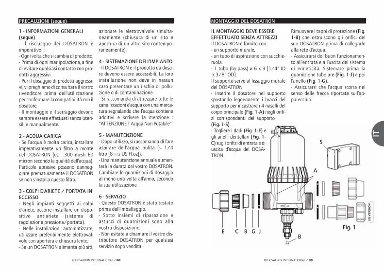
IL MONTAGGIO DEVE ESSEREEFFETTUATO SENZA ATTREZZIIl DOSATRON è fornito con : - un supporto murale,- un tubo di aspirazione con succhie-ruola.- 1 tubo (by-pass) ø 6 x 9 [1/4" IDx 3/8" OD].
Il supporto serve al fissaggio muraledel DOSATRON.- Inserire il dosatore nel supportospostando leggermente i bracci delsupporto per incastrare i 4 naselli delcorpo principale (Fig. 1-A) negli orifi-zi corrispondenti del supporto(Fig. 1-S).- Togliere i dadi (Fig. 1-E) egli anelli dentellari (Fig. 1-C) sugli orifizi di entrata e diuscita d’acqua del DOSA-TRON.
Rimuovere i tappi di protezione (Fig.1-B) che ostruiscono gli orifici delsuo DOSATRON prima di collegarloalla rete d’acqua.- Assicurarsi del buon funzionamen-to all’entrata e all’uscita del sistemadi ermeticità. Sistemare prima laguarnizione tubolare (Fig. 1-J) e poil’anello (Fig. 1-G).- Assicurarsi che l’acqua scorra nelsenso delle frecce riportate sull’ap-parecchio.
MONTAGGIO DEL DOSATRON
A
Fig. 1E C B G J
B
S
1 - INFORMAZIONI GENERALI(segue)- Il risciacquo dei DOSATRON èimperativo :- Ogni volta che si cambia di prodotto,- Prima di ogni manipolazione, a finedi evitare qualsiasi contatto con pro-dotti aggressivi.- Per il dosaggio di prodotti aggressi-vi, vi preghiamo di consultare il vostrorivenditore prima dell’utilizzazioneper confermare la compatibilità con ildosatore.- Il montaggio e il serraggio devonosempre essere effettuati senza uten-sili e manualmente.
2 - ACQUA CARICA- Se l’acqua è molta carica, installareimperativamente un filtro a montedel DOSATRON (es. : 300 mesh 60micron secondo la qualità dell’acqua).Particole abrasive possono danneg-giare prematuramente il DOSATRONse non s’installa questo filtro.
3 - COLPI D’ARIETE / PORTATA INECCESSO- Negli impianti soggetti ai colpid’ariete, occorre installare un dispo-sitivo antiariete (sistema diregolazione pressione/portata).- Nelle installazioni automatizzate,utilizzare preferibilmente elettroval-vole con apertura e chiusura lente.- Se un DOSATRON alimenta più siti,
azionare le elettrovalvole simulta-neamente (chiusura di un sito eapertura di un altro sito contempo-raneamente).
4 - SISTEMAZIONE DELL’IMPIANTO- Il DOSATRON e il prodotto da dosa-re devono essere accessibili. La loroinstallazione non deve in nessuncaso presentare un rischio di pollu-zione o di contaminazione.- Si raccomanda di attrezzare tutte lecanalizzazioni d’acqua con una marca-tura segnalando che l’acqua contieneadditivi e scrivere la menzione :"ATTENZIONE ! Acqua Non Potabile".
5 - MANUTENZIONE- Dopo utilizzo, si raccomanda di fareaspirare dell'acqua pulita (~ 1/4litro [8 1/2 US Fl.oz]).- Una manutenzione annuale aumen-terà la durata del vostro DOSATRON.Cambiare le guarnizioni di dosaggioal meno una volta all’anno, secondola sua utilizzazione.
6 - SERVIZIO- Questo DOSATRON è stato testatoprima dell’imballaggio.- Sotto insiemi di riparazione eastucci di guarnizioni sono allavostra disposizione.- Non esitate a chiamare il vostro dis-tributore DOSATRON per qualsiasiservizio dopo vendita.
© DOSATRON INTERNATIONAL / 89
IT
© DOSATRON INTERNATIONAL / 88
PRECAUZIONI (segue)

© DOSATRON INTERNATIONAL / 91
IT
© DOSATRON INTERNATIONAL / 90
ATTENZIONE ! - Lasciare la succhieruola a circa 10 cm dal fondo del ser-batoio di soluzione per evitare di aspirare le particelle insolubili chepossono danneggiare il corpo dosatore (Fig. 3).- Non posare la succhieruola a terra.
NOTA : L'altezza di aspirazione è di 4 metri al massimo [13 ft].
Collegare il tubo munito della succhieruola ed immergerlo nella soluzioneda dosare
Il livello della soluzione non deve essere mai al di sopra dell’entratadell’acqua nel DOSATRON (al fine di evitare il sifonaggio).
MONTAGGIO DEL DOSATRON (segue)
10 c
m
Fig. 3
QUELLO CHE NON SI DEVE FARE
QUELLO CHE SI DEVE FARE
▼
▼
Fig. 4
Metodo da seguire per il collega-mento del tubo PVC : - Procedere come per il collegamentodel tubo polietilene o polipropilenema prima di stringere, rivestire dicolla PVC il posto che occuperàl’anello dentellato.- Spingere in avanti l’anello dentella-to in posizione, allargandolo con ipollici posti nella fessura (Fig. 2-C)per evitare di raschiare la colla. Dopoprocedere al serraggio del dado.
NOTA : Aspettare 1 ora prima dellamessa in pressione del circuito. Perogni smontaggio ulteriore, bisognasapere che la colla PVC non aderisceall’anello dentellato in poliacetale.
Il collegamento dell’apparecchio alla rete d’acqua può essere effettuato contubi flessibili di 40 millimetri di diametro interno, fissati con collari e raccor-di girevoli di Ø 40 x 49 mm [3/4”]. Assicurarsi che l’acqua scorra nel sensodelle frecce riportate sull’apparecchio.
Il DOSATRON è venduto con un tubo di aspirazione (che può essere accor-ciato secondo i bisogni dell’installazione) che permette la sua utilizzazionecon un serbatoio di grande contenenza. Questo tubo deve essere dotatoobbligatoriamente della succhieruola. Per il collegamento di questo tubo,vedere il capitolo corrispondente.
MONTAGGIO DEL DOSATRON (segue)
Metodo da seguire per il collega-mento del tubo polietilene epolipropilene : - Collocare nel tubo tagliato precisa-mente e smussato, il dado (Fig. 2-E)e l’anello dentellato (Fig. 2-C).- Introdurre il tubo negli orifizi dientrata e di uscita d’acqua (Fig. 2).- Spingere fino all’arresto l’anellodentellato (Fig. 2-C) sull’entrata,poi l’altro sull’uscita dell’acqua.- Stringere il dado (Fig. 2-E).
E
Fig. 2
C
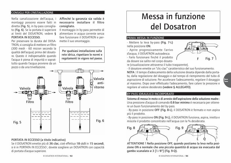
© DOSATRON INTERNATIONAL / 93
IT
© DOSATRON INTERNATIONAL / 92
Messa in funzione del Dosatron
PRIMA MESSA IN FUNZIONE- Mettere la leva by-pass (Fig. 7-L)nella posizione ON.- Aprire progressivamente l’arrivod’acqua, il DOSATRON autoadesca.- Farlo funzionare finché il prodottoda dosare sia salito nel corpo dosato-re (visualizzazione attraverso il tubo trasparente).- Il dosatore emette un “clic-clac” caratteristico del suo funzionamento.NOTA : Il tempo d’adescamento della soluzione dosata dipende dalla porta-ta, dalla regolazione del dosaggio e dal tempo di riempimento del tubo diaspirazione di soluzione. Per accelerare l’adescamento, regolare il dosaggioal massimo. Dopo aver effettuato l’adescamento, fare calare la pressione eregolare al valore desiderato (vedere § ALLEGATO).
Sistema di messa in moto o di arresto dell’aspirazione della soluzione madre : Una pressione d’acqua di comando 0.8 bar minimo é necessaria per ottene-re un buon funzionamento del by-pass.- By-pass in posizione OFF (Fig. 8-L), il DOSATRON è fermato e non aspirapiù il prodotto.- By-pass in posizione ON (Fig. 9-L), il DOSATRON funziona, aspira, inietta emiscela il prodotto concentrato nell'acqua con la % desiderata.
ATTENTIONE ! Nella posizione OFF, quando postiamo la leva nella posi-zione ON e normale che una piccola quantità di acqua sia evacuata dalgambo scanalato ø 3 [1/8"] (Fig. 9-Q).
CONSIGLI PER L’INSTALLAZIONE
PORTATA IN ECCESSO (a titolo indicativo)Se il DOSATRON emette più di 36 clac, cioè effettua 18 cicli in 15 secondi,si è in PORTATA IN ECCESSO ; dovete scegliere un DOSATRON con capacitàdi portata d’acqua superiore.
Nella canalizzazione dell’acqua, imontaggi possono essere fatti indiretta (Fig. 5), in by-pass consiglia-to (Fig. 6). Se la portata è superioreai limiti del DOSATRON, vedere §PORTATA IN ECCESSO.Per preservare la durata del DOSA-TRON, si consiglia di mettere un filtro(300 mesh - 60 micron secondo laqualità dell’acqua) prima del dosato-re. Questo è indispensabile quandol’acqua è piena di impurità e soprat-tutto quando l’acqua proviene da unpozzo o da una trivellazione.
Affinché la garanzia sia valida ènecessario installare il filtroconsigliato.Il montaggio in by-pass permette dialimentare in acqua corrente senzafare funzionare il DOSATRON e per-mette il suo smontaggio.
Per qualsiasi installazione sullarete idrica, rispettare le normi eregolamenti in vigore nel paese.
Valvolaanti-
ritornoValvola Valvola
Filtro Filtro
Fig. 6Fig. 5
Fig. 7
Fig. 8 Fig. 9
F
L L Q
BY-PASS IDRAULICO INCORPORATO

© DOSATRON INTERNATIONAL / 95
IT
© DOSATRON INTERNATIONAL / 94
BY-PASS TELECOMANDATO
Sistema di messa in moto o di arresto dell’aspirazione della soluzione madre : Una pressione d’acqua di comando 0.8 bar minimo è necessaria per ottene-re un buon funzionamento del by-pass.NOTA : Con l’utilizzazione del by-pass telecomandato, la leva di comandomanuale (Fig. 10-L) deve trovarsi sulla posizione ON.
BY-PASS TELECOMANDATO (segue)
Dispositivo automatico antisifonnaggio di soluzione dosata : - Ristabilisce automaticamente la pressione atmosferica nell’impianto incaso di depressione accidentale (Fig. 11).La sua utilizzazione dipende dalla normativa sanitaria vigente nel nostro paese.- Conformarsi alle disposizioni previste.- Per metterlo in servizio, svitare il dado (Fig. 11-E), togliere la rondellametallica piena (Fig. 11-P) e sostituirla con la rondella cava (Fig. 11-C) chesi trova nel pacco.- Riavvitare il dado (Fig. 11-E).
Mettere in by-pass telecomandato : - Apertura dell’ elettrovalvola.Azionata aperta : 1 verso 2 > Utilizzazione : Entrata d’acqua di comando
by-pass - Mettere in by-pass (arresto del DOSATRON) 3 > Scappamento chiuso
Messa in moto del DOSATRON : - Chiusura dell’ elettrovalvola. Non azionata chiusa : 2 verso 3 > Scappamento : Scappamento dell’acqua
di comando fuoriMessa in moto del DOSATRON 1 > Pressione in attesa
Fig. 10
Fig. 11
F
C
E
Sfera
Membranadi gomma
P
F
Q : Gambo scanalato ø 3 [1/8"] (consegnata con il DOSATRON)
Fluido di comando (aria o acqua)Pressione : da 0.8 fino a 8 bar
O : Elettrovalvola o valvola con 3 vie in L
(non consegnata con il DOSATRON)
T : Tubo flessibile ø 6 x 9[1/4" ID] x [3/8" OD]
*esempio : nel caso l’uscita del dosatore sia più bassa dell’entrata.

© DOSATRON INTERNATIONAL / 97
IT
© DOSATRON INTERNATIONAL / 96
Fig. 12
Guarnizion
PULIZIA DEL FILTRO INCORPORATO 500 microns - 32 mesh
Smontaggio del filtro- Chiudere l’arrivo d’acquae fare calare la pressione.Prima di accedere alfiltro, seguire leistruzioni cronologi-che di smontaggiodescritte al § SOS-TITUZIONE DELLEPISTONE MOTORE.- Rimuovere il corpodosatore.- Svitare manualmente lacampana e rimuoverla (Fig. 13).- Rimuovere il pistone motore(Fig. 14-M).- Rimuovere il filtro (Fig. 14-F).- Rimuovere la guarnizione di tenuta stagna (Fig. 14-N).- Pulire il filtro e la guarnizione con acqua pulita.
Rimontaggio del filto- Prima del rimontaggio, assicurarsi che le portate del filtroe della guarnizione di tenuta stagna (Fig. 14-N) sul corpo e sulla campanasiano pulite. Cambiare la guarnizione se occorre.- Lubrificare la filettura del corpo della pompa (grasso silicone).- Operazioni inverse dello smontaggio.Importante : in ogni caso il serraggio deve essere fatto a mano.
CONVERSIONI - Misure internazionali
Principio : Regolazione all' 1% ⇒ 1/100 = 1 volume di prodotto concen-trato per 100 volumi d’acqua.Es. : Regolazione al 2 % ⇒ 2/100 = 2 volumi di prodotto concentrato per100 volumi d’acqua.Rapporto ⇒ 1/50.
ManutenzioneRACCOMANDAZIONI
1 - Quando si utilizzano prodotti solu-bili da mettere in soluzione, siconsiglia di smontare periodicamentela parte completa di dosaggio (§ SOS-TITUZIONE DELLA GUARNIZIONEDI DOSAGGIO), di sciacquarlaabbondantemente con acqua pulita,di rimontarla dopo aver lubrificato laguarnizione con silicone (Fig. 12).
2 – Una presa d’aria, un’impurità o l’attacco chimi-co di una guarnizione può interrompere il buonfunzionamento del dosaggio. Si raccomanda diverificare periodicamente che il prodotto sia corret-tamente aspirato nel DOSATRON.
3 - Prima di rimettere il DOSATRON in moto,all’inizio della stagione, rimuovere il pistonemotore ed immergerlo in acqua tiepida (< 40° C)per qualche ora. Tale operazione permette di elimi-nare i depositi secchi sul pistone motore.
SCARICO DEL DOSATRON (precauzioni contro il gelo)
- Chiudere l’arrivo dell’acqua e fare calare la pressione a zero.- Rimuovere la parte dosaggio. - Rimuovere la campana e il motore, § PULIZIA DEL FILTRA INCORPORATO. - Staccare i raccordi all’entrata e all’uscita dell’acqua.- Svuotare il corpo principale dopo averlo rimosso dal supporto murale esvuotarlo.- Procedere al rimontaggio dopo aver pulito la guarnizione di tenuta stagna(Fig. 14-N pagina seguente).
Periodicità : Una volta al mese secondo l’uso.
Fig. 13
Fig. 14
M
N
F

© DOSATRON INTERNATIONAL / 99
IT
© DOSATRON INTERNATIONAL / 98
REGOLAZIONE DEL DOSAGGIO (segue)RACCORDO DEL TUBO DI ASPIRAZIONE
Nel caso di raccordo a un DOSATRON già utilizzato, consultare imperativa-mente il § PRECAUZIONI.
- Svitare il dado (Fig. 15-E) situato in basso, nella parte dosaggio, ed infila-re il tubo di aspirazione nel dado.- Spingere a fondo il tubo sull’estremità scanalata e riavvitare il dado a mano.- Per il tubo di aspirazione Ø 20 (D8RV et D8R150), svitare con un cacciavite,il collare (Fig. 16-C) montato nel tubo di aspirazione. - Infilare il tubo a fondo nell’estremità scanalata, avvitare di nuovo il collare.
Modello D8R150- Allentare il dado di ritenuta (Fig. 17-B). - Avvitare o svitare la boccola di regolazione(Fig. 17-D) per portare la parte superiore dellaboccola sul numero di dosaggio desiderato.- Ristringere il dado di ritenuta (Fig. 17-B).
RICORDIAMO che la quantità del prodottoiniettato è proporzionale alla quantità d’ac-qua che entra nel DOSATRON. 1 % => 1/100, rapporto di 100 volumi d’acqua + 1 volume di prodotto iniettato.
REGOLAZIONE DEL DOSAGGIO (fuori pressione)
ATTENZIONE ! Non utilizzare attrezzi.La regolazione deve essere effettua-ta fuori pressione, dopo averechiuso l’arrivo d’acqua.Modello D8R- Allentare il dado di ritenuta (Fig. 17-B). - Avvitare o svitare la boccola di regolazio-ne (Fig. 17-D) per portare la partesuperiore della boccola sul numero didosaggio desiderato.- Ristringere il dado di ritenuta (Fig. 17-B).
Fig. 15
ø 12 ø 20
D8R150D8R
ø 20(opzione “V”)
Fig. 16
C
E
Fig. 17
B
D
Fig. 17
B
D
SOSTITUZIONE DELLE GUARNIZIONI DELLA PARTE DOSAGGIO (fuori pressione)
Periodicità : al meno una volta all’anno.ATTENZIONE ! Non si deve utilizzare attrezzi o utensili metallici.
CONSIGLIO : Prima di qualsiasi smontaggio della parte dosaggio, si consi-glia di fare funzionare il DOSATRON aspirando dell’acqua pulita, persciacquare il sistema d’iniezione. In tal modo si evita qualunque contattocon i prodotti eventualmente presenti nella parte dosaggio. Portare occhia-li e guanti di protezione durante ogni intervento di questo tipo !
METODO PER TOGLIERE UNA GUARNIZIONEFig. 18 : Tra il pollice e l’indice, stringere ilpezzo e la guarnizione; rispingerlo verso il latoopposto per deformarlo.Fig. 19 : Aumentare la deformazione perprendere il pezzo della guarnizione che spor-ge, toglierlo della sua scanalatura. Pulire laportata della guarnizione senza attrezzi.Il rimontaggio si fà a mano.È molto importante che la guarnizione, unavolta a posto, non stia attorcigliata, altrimentil’ermeticità non sarebbe rispettata.
Fig. 18
Fig. 19

© DOSATRON INTERNATIONAL / 101
IT
© DOSATRON INTERNATIONAL / 100
SOSTITUZIONE DELLE GUARNIZIONI DELLA PARTE DOSAGGIO (segue)
PULIZIA E RIMONTAGGIO DELLA VALVOLA DI ASPIRAZIONE
Fig. 21
Fig. 22
- Chiudere l’arrivo d’acqua e fare calare la pressione a zero.Modello D8R- Svitare il dado (Fig. 20/21-E) e rimuovere il tubo d’aspirazione.- Per il tubo di aspirazione Ø 20 (opzione V), svitare con un cacciavite, il col-lare (Fig. 21-C) montato nel tubo di aspirazione.- Svitare e togliere il dado nero (Fig. 20/21-N). - Tirare verso il basso per rimuovere l’insieme della valvola di aspirazione. - Risciacquare abbondantemente con acqua le diverse parti, rimontarlenell’ordine dello schema (Fig. 20/21-P) e verificare che la molla sia beneattiva.- Rimontare nel senso inverso allo smontaggio a mano.
Modello D8R150- Allentare il dado di ritenuta (Fig.22-A).- Svitare e rimuovere il dado di ser-raggio della valvola di aspirazione. - Risciacquare abbondantementecon acqua le diverse parti, rimon-tarle nell’ordine dello schema (Fig.22-P) e verificare che la molla siabene attiva.- Rimontare nel senso inverso allosmontaggio a mano.
N
A
N
C
P
P
P
E E
SOSTITUZIONE DELLE GUARNIZIONI DELLA PARTE DOSAGGIO (segue)
SOSTITUZIONE DELLE GUARNIZIONI DELLA PARTE DOSAGGIO- Chiudere l’arrivo d’acqua e fare calare la pressione a zero. - Smontare il tubo di aspirazione di prodotto, svitare la parte dosaggio comedescritto nel capitolo precedente e tirare verso il basso per liberarla. - Cambiare la guarnizione del corpo dosatore (Fig.23-O) e quella del tuffante(Fig. 23-P).- Per il D8R, svitare il dado di contegno della valvola di aspirazione (Fig.23-E)stando attento a non perdere gli elementi della valvola, poi cambiare la guar-nizione torica (Fig. 23-T) e la guarnizione della valvola (Fig. 23-C).- Per il D8R150, tenendo il dado (Fig. 23-S), svitare la camicia dosatore(Fig. 23-U) e tirare verso il basso.- Rimontare nel senso inverso allo smontaggio a mano.Nota : La scala di dosaggio (Fig. 23-L) deve essere posizionata di fronte a voi.- Avvitare l’anello di ritenuta (Fig. 23-R) fino al bloccaggio.
Fig. 23
D8R
opzione V
opzione V
D8R150
O
U
PPS
L
E
CT
R
Infilare la partedosaggio a fondo
in appoggio.Girare legger-
mente a destra oa sinistra fino al
bloccaggio inrotazione del
corpo dosatore.
Fig. 20
O

© DOSATRON INTERNATIONAL / 103
IT
© DOSATRON INTERNATIONAL / 102
Designazione/riferimento
RIF. / N° Serie : ................................................................................................................................ESEMPIO D8R BP V AF P H ii
Tipo di DOSATRONBP : By-pass integratoV : Prodotti Viscosi(200-400 cSt)Guarnizioni Dosaggio : AF = PH 7-14VF = PH 1-7Colore : - = Blu
P = BiancoR = RossoV = VerdeJ = GialloO = Arancio
H = HastelloyAltre opzioni(da precisarci)
D8RVF06140745D8RVF06140745
RIF. / N° Serie
SOSTITUZIONE DEL PISTONE MOTORE (fuori pressione)
- Chiudere l’arrivo d’acqua e fare calare la pressione a zero. - Smontare la parte dosaggio come indicato al § precedente.- Svitare la campana a mano (Fig. 24-C) e rimuoverla.- Uscire il pistone motore (Fig. 24-M) tirando verso l’alto, prendendosi curadi guidare la guarnizione (Fig. 24-J). - Cambiare e rimontare nel senso inverso allo smontaggio.- Cambiare le guarnizioni della valvola e del gambo scanalato.- Rimontare il sottogruppo dosaggio.
Fig. 24
M
J
M
C C
D8R D8R150

© DOSATRON INTERNATIONAL / 105
IT
© DOSATRON INTERNATIONAL / 104
Guasti possibiliGUASTI CAUSE SOLUZIONI
Pistone motorePistone motore Rilanciare il pistone motorebloccato azionandolo manualmente
Portata in eccesso 1. Ridurre la portata, rimet-tere in funzionamento
2. Verificare la presenzadelle guarnizioni dellevalvole del motore
Il by-pass è chiuso o Mettere la leva in mezzo aperto posizione ONPistone motore rotto Inviare il DOSATRON al
vostro distributore
Filtro ostruito Pulire il filtro : § p97DosaggioErogazione nella Valvola di aspirazione Pulire o cambiare.vasca di prodotto sporca, guasta
o mancante.
Il prodotto non Il pistone motore Vedi Pistone motore.viene aspirato è fermo.
Presa d’aria al livello Verificare il tubo del tubo di aspirazione. di aspirazione e il
serraggio dei suoi dadi.
Tubo di aspirazione Pulire o cambiare.ostruito o succhieruolasporca.
Guarnizione della Pulire o cambiare.valvola di aspirazioneguasta, installata maleo sporca.
Guarnizione di tuffante Pulire o cambiare.guasta, installata maleo sporca.
GUASTI CAUSE SOLUZIONI
DosaggioIl prodotto non Screpolatura nel Cambiareviene aspirato corpo dosatore
Sotto dosaggio Presa d’aria 1. Verificare il serraggiodei dadi della partedosaggio
2. Verificare lo stato deltubo di aspirazione
Guarnizione della Pulire o cambiarevalvola di aspirazione guasta o sporca
Eccesso di portata Ridurre la portata
Guarnizione di tuffante Cambiareguasta
Screpolatura nel Cambiarecorpo dosatore
Fughe d’acquaFughe a prossimità Guarnizione della Installare correttamente dell'anello metallico camicia guasta, o cambiaredi fissaggio sotto installata male o il corpo di pompa assente
Fughe tra la ghiera Guarnizione del corpo Installare correttamente di regolazione e dosatore guasta, o cambiarel’anello di installata male obloccaggio assente
Fughe tra il corpo Guarnizione di Installare correttamente, e la campana campana guasta, pulire la sede della
installata male o guarnizione o sostituireassente
DOSATRON INTERNATIONALDECLINA OGNI RESPONSABILITÀ IN CASO DI UTILIZZAZIONE
NON CONFORME AL MANUALE D’USO
Il vostro DOSATRONnon si mette in funzionamento o siferma

© DOSATRON INTERNATIONAL / 107
IT
© DOSATRON INTERNATIONAL / 106
GaranziaDOSATRON INTERNATIONAL S.A. siimpegna a sostituire tutto particolarericonosciuto difettoso di originedurante un periodo di dodici mesi apartire dalla data di acquisto delcompratore iniziale.
Per ottenere la sostituzione sottogaranzia, l’apparecchio o la parte diricambio deve esse rinviata con laprova di acquisto iniziale al fabbricanteo al distributore autorizzato.Il detto materiale potrà esseredichiarato difettoso dopo verificadei servizi tecnici del fabbricante odel distributore.
L’apparecchio deve essere sciacquatoper pulirlo di tutto prodotto chimico einviato al fabbricante o al distributorecon porto assegnato, sarà poi rinviatogratuitamente dopo riparazione secoperto dalla garanzia.
Gli interventi realizzati sotto garanzianon potranno aumentare il tempodella garanzia stessa.
Questa garanzia si applica unicamenteai difetti di fabbricazione.
Questa garanzia non copre i difetticonstatati provenienti da un’instal-lazione anormale dell’apparecchio,della messa in opera di attrezzaturenon appropriate, da un difetto di ins-
tallazione o di manutenzione, di unincidente ambientale o dalla corrosione dovuta a corpi stranieri oa liquidi trovati all’interno o a prossi-mità dell’apparecchio.
Per il dosaggio di prodotti aggressivi,Vi preghiamo di consultare il Vsrivenditore prima dell’utilizzazioneper confermare la compatibilità conil dosatore.
La garanzia non comprende le guar-nizioni (parti che si usano) ne i dannicausati dalle impurità dell’acqua,come la sabbia.
Un filtro (300 mesh - 60 micron oinferiore) deve essere installatoprima dell’apparecchio per convali-dare questa garanzia.
DOSATRON INTERNATIONAL S.A.declina tutta responsabilità se l’appa-recchio viene utilizzato sotto condizioniche non sono conformi alle prescrizioniet tolleranza del manuale d’uso.
Non esiste garanzia implicita o esplici-ta relativa ad altri prodotti o accessoriutilizzati con gli apparecchi dellaDOSATRON INTERNATIONAL S.A.
Non esitare a chiamare il Vostro distri-butore o la Dosatron per qualsiasiassistenza dopo vendita.
PER CONOSCERE LA VOSTRA PORTATA
UN METODO SEMPLICEÈ COSTITUITO DA :
La cadenza del motore è proporzionale alla portata d’acqua che passa attraverso l’apparecchio.
Nel suo movimento di va e vieni, il pistone motore emette i clac :
Contare il numero di clac in 30 secondi x 100 = Portata d’acqua in litri/ora.
NOTA : Questo metodo di calcolo non può sostituire un misuratore diportata. È dato esclusivamente a titolo indicativo.
Un motore idraulico volumetrico conpistone che aziona :
Un pistone di dosaggio.
1 volta in posizione alta
1 volta in posizione bassa

© DOSATRON INTERNATIONAL / 109
ES
© DOSATRON INTERNATIONAL / 108
Español
¡ Importante ! El número de serie de su DOSATRON aparece en el cuerpo de bomba.Le rogamos apunte éste número en la parte destinada aello más abajo y lo mencione cuando se ponga en contac-to con su vendedor para cualquier información.
Ref. : ................................................................................
N°Serie : ........................................................................
Fecha de compra : ..........................................................
Vd. acaba de adquirir un Dosificador Proporcional DOSATRON INTERNATIONAL.Le felicitamos por su elección. Este modelo ha sido elaborado gracias a la experien-cia de más de 25 años.Nuestros ingenieros han situado la serie de los DOSATRON en primera línea de loque podía ser la evolución técnica de los Dosificadores Proporcionales SinElectricidad.La elección de los materiales que forman parte de la fabricación fue de lo másminuciosa a fin de resistir a los ataques químicos de todos o, por lo menos, de lamayoría de los productos a dosificar existentes en el mercado. Este DOSATRON serevelará, con el tiempo, un aliado de los más fieles. Una limpieza regular garanti-zará un funcionamiento en el cual la palabra avería ya no tendrá cabida.
SÍRVASE LEER ATENTAMENTE ESTE MANUALANTES DE PONER EN SERVICIO EL APARATO
Este documento no constituye un compromiso contractual y se suministra solamente a título orientativo. La sociedad DOSATRON INTERNATIONAL se reserva el derecho de modificar sus aparatos en cualquier momento.
© DOSATRON INTERNATIONAL S.A. 2007

© DOSATRON INTERNATIONAL / 111
ES
© DOSATRON INTERNATIONAL / 110
INSTALACIÓN PÁGINA
Recomendaciones ............................................................................113
Montaje del Dosatron ......................................................................115
Recomendaciones de instalación..................................................118
PUESTA EN SERVICIO
Primera puesta en servicio ............................................................119
By-pass hidraulico incorporado ....................................................119
By-pass automatico ..........................................................................120
MANTENIMIENTO
Recomendaciones ............................................................................122
Vaciado del Dosatron ......................................................................122
Limpieza del filtro incorporado ....................................................123
Conversiones - medidas internacionales....................................123
Conexión del tubo de aspiración..................................................124
Ajuste de la dosificación ................................................................124
Cambio de las juntas de la parte dosificación..........................125
Cambio del pistón motor ................................................................128
DENOMINACIÓN/REFERENCIA ................................................129
POSIBLES INCIDENCIAS................................................................130
GARANTIA ..........................................................................................132
ÍndiceCARACTERÍSTICAS
Caudal nominal de agua de funcionamiento :500 l/h mín. - 8 m3 máx. [2.2 Fl oz/min - 40 US GPM]
Presión de funcionamiento : barPSI
Dosificación ajustable exteriormente o fija : %ratio
Caudal de inyección del producto concentrado : Mín. l/h - Máx. l/hUS Fl. oz/mínUS GPM/máx
Temperatura máxima de funcionamiento : 40 °C [104 ° F]
Conexión (NPT/BSP gas macho) : Ø 40x49 mm [1” 1/2 M]
Cilindrada del motor hidráulico (cada dos pistonadas del pistón) : aprox. 1.6 l [0.4224 US Gallons]
COMPOSICIÓN DEL PAQUETE : 1 DOSATRON / 1 soporte mural para DOSATRON / 1 tubo de aspiración para la solución / 1 filtro de aspiración /1 manual de utilización
¡ CUIDADO ! El DOSATRON no está regulado de antemano, para ello referirse al § AJUSTE DE LA DOSIFICACIóN
0.15 - 82 - 110
0.2 - 21:500 - 1:50
1 - 1600.560.70
D 8 R
DIMENSIONES
Diámetro : cm ["]
Altura total : cm ["]
Anchura total : cm ["]
Peso : ± kg [lbs]
Dimensiones del embalaje : cm["]
Peso del paquete : ± kg [lbs]
18.4 [7 1/4]
59.1 [23 1/4]
31 [12 1/4]
4 [8.8]
0.15 - 82 - 110
1 - 51:100 - 1:20
5 - 4002.8
1.76
D 8 R 150
18.4 [7 1/4]
66.7 [26 1/4]
31 [12 1/4]
4.5 [10]
60 x 36.5 x 24[23 2/3 x 14 1/3 x 9 1/2]
82 x 26 x 21[32 1/4 x 10 1/4 x 8 1/4]
5.5 [12.15] 7 [15.5]

© DOSATRON INTERNATIONAL / 113
ES
© DOSATRON INTERNATIONAL / 112
InstalaciónRECOMENDACIONES
1 - INFORMACIONES GENERALES- Cuando se conecta una instalación,bien a la red pública de agua o a supropio punto de agua, es imperativocumplir la normativa de proteccióny desconexión.DOSATRON recomienda un desco-nectador para evitar lacontaminación de la red de agua.- En caso de que la instalación estémás alta que el propio DOSATRON,existe el riesgo de retorno de agua alDOSATRON ; por lo tanto, se reco-mienda instalar una válvulaantirretorno aguas abajo del aparato.- No instalar el DOSATRON sobre unrecipiente de ácido o de un productoagresivo, y protegerlo contra posi-bles emanaciones de producto.- El DOSATRON ha de estar protegi-do contra el hielo y debe estarsituado lejos de fuentes de calorimportantes.- No instalar el DOSATRON en el cir-cuito de aspiración de la bomba deimpulsión (efecto sifón).- El operador debe ponerse frente alDOSATRON, llevar gafas y guantesde protección para cualquier inter-vención.
- Para asegurar la precisión de ladosificación, el cambio anual de lasjuntas de la parte dosificación per-manece bajo la responsabilidad delutilizador.- El utilizador será el único responsa-ble de la selección de lasregulaciones del DOSATRON paraobtener la dosificación deseada.El utilizador debe respetar rigurosa-mente las recomendaciones delfabricante de producto.- Asegurarse de que el caudal y lapresión de agua de la instalaciónson conformes con las característi-cas del DOSATRON.- Una toma de aire, una impureza ouna rotura de junta puede interrum-pir el buen funcionamiento de ladosificación. Se recomienda verificarperiódicamente que el productoconcentrado por dosificar va siendoaspirado en el DOSATRON.- Cambiar el tubo de aspiración delDOSATRON en cuanto parezca dete-riorado por el concentradodosificado.- Al final del uso, poner el sistemafuera de presión (recomendado).
Preciso, sencillo y fiable
Pistón motor
Agua
Solución agua+ % producto
Pistón dosificador
Ajuste de ladosificación (%)
Producto concentradopara dosificar
Instalado en una red de agua, el DOSATRON funciona sin electri-cidad : utiliza la presión del agua como fuerza motriz. Asíaccionado, aspira el producto concentrado en un recipiente, lodosifica al porcentaje deseado, lo homogeneiza en la cámaramezcladora con el agua motriz. La solución realizada está enton-ces enviada a la salida del aparato. La dosis de productoinyectada es siempre proporcional al volumen de agua que pasapor el DOSATRON, cualesquiera que sean las variaciones de caudal o de presión.

EL MONTAJE DEBE HACERSE SINHERRAMIENTASEl DOSATRON se entrega con : - un soporte mural,- un tubo de aspiración con filtro.- 1 tubo (by-pass) ø 6 x 9 [1/4" ID x 3/8" OD]El soporte permite la fijación muraldel DOSATRON.- Colocar las colas de milano delDOSATRON (Fig. 1-A) en el soportemural (Fig. 1-S).- Retirar las tuercas (Fig. 1-E) y losanillos de fijación (Fig. 1-C) situadosen los orificios de entrada y de salidadel agua del DOSATRON.
- Retirar los tapones de proteccióndel DOSATRON (Fig. 1-B) que obs-truyen los orificios de su DOSATRONantes de conectarlo a la red de agua.- Controle la posición correcta en laentrada y salida del sistema deestanqueidad. Coloque primero lajunta tórica (Fig. 1-J) y luego el anil-lo de fijación (Fig. 1-G).- Asegúrese de que el agua fluya en elsentido de las flechas por el aparato.
MONTAJE DEL DOSATRON
A
Fig. 1E C B G J
B
S
© DOSATRON INTERNATIONAL / 115
ES
© DOSATRON INTERNATIONAL / 114
1 - INFORMACIONES GENERALES(continuación)- El enjuague del DOSATRON esimprescindible : . después de cada cambio de producto.. antes de cada manipulación, paraevitar el contacto con productosagresivos.- Para la dosificación de productosagresivos, le rogamos consulte el dis-tribuidor oficial DOSATRON antes decualquier utilización para confirmarla compatibilidad del producto con eldosificador.- No se debe utilizar herramientaspara montar y apretar.
2 - AGUAS CARGADAS- En caso de aguas cargadas muyduras, coloque imperativamente unfiltro con tamiz antes del DOSATRON(300 mesh – 60 micras según la cali-dad de su agua). Si no se instala estefiltro, partículas abrasivas causaránel desgaste prematuro del DOSA-TRON.
3 - GOLPES DE ARIETE / CAUDALEXCESIVO- En instalaciones sometidas a gol-pes de ariete, es necesario instalarun dispositivo antigolpes de ariete(sistema de regulación presión/cau-dal).- En las instalaciones automatizadas,utilice preferentemente electroválvu-las de apertura y cierre lentos.
- En caso de que un DOSATRON ali-mente varios sectores, accionar laselectroválvulas simultáneamente(cierre de un sector y abertura de unotro sector al mismo tiempo).
4 - LUGAR DE LA INSTALACION- El DOSATRON y el concentrado quehay que dosificar deben ser fácil deacceso. Su instalación no debe pre-sentar ningún riesgo de polución ode contaminación.- Se recomienda marcar todas lastuberías de agua señalando que elagua contiene aditivos, mencionar :
“ ¡ CUIDADO ! Agua No Potable”.
5 - MANTENIMIENTO- Después de utilizarlo, se recomien-da aspirar agua (~ 1/4 litro [8 1/2
US Fl.oz]).- Un mantenimiento anual le permi-tirá alargar la vida de suDOSATRON. Cambiar al menos cadaaño las juntas de inyección y el tubode aspiración.
6 - SERVICIO- Este DOSATRON se sometió à prue-bas antes de embalarle.- Subconjuntos de reparación y bolsasde juntas son disponibles.- Para cualquier servicio posventa,llame su distribuidor o DOSATRON.
RECOMENDACIONES (continuación)

© DOSATRON INTERNATIONAL / 117
ES
© DOSATRON INTERNATIONAL / 116
¡ ATENCIÓN ! Dejar el filtro de aspiración a 10 cm del fondo del recipien-te de solución para evitar aspirar las partículas no solubles que puedandañar el cuerpo dosificador (Fig. 3).- No colocar el filtro de aspiración en el suelo.
NOTA : La altura de aspiración es de 4 metros (máx) [13 ft].
- Conectar el tubo provisto de su filtro de aspiración y sumergirlo en la solu-ción a dosificar.
El nivel de la solución nunca debe estar encima de la entrada de agua enel DOSATRON (a fin de evitar el efecto sifón).
MONTAJE DEL DOSATRON (continuación)
10 c
m
Fig. 3
LO QUE NO DEBE HACER
LO QUE DEBE HACER
▼
▼
Fig. 4
Técnica de empalme para tubos dePVC :- Proceder como para el empalme detubos de polietileno y polipropileno,pero antes de apretar, untar con colade PVC el sitio del anillo de fijación.- Posicionar el anillo de fijación sepa-randolo con los dos pulgares puestoen la ranura (Fig. 2-C) pour ne pasracler la colle, despues, apretar latuerca.
NOTA : Esparar 1 hora antes de ponera presión el circuito. Para cualquierdesmontaje ulterior, es necesariosaber que la cola PVC nunca adhiereal anillo de fijación de poliacetal.
La conexión del aparato a la red de agua puede realizarse mediante tubosflexibles de 40 mm de diámetro interior fijados con anillos y racores girato-rios de ø 40 x 49 mm [1"1/2]. Asegúrese de que el agua fluya en el sentidode las flechas por el aparato.
El DOSATRON se entrega con un tubo de aspiración que permite su uso conun recipiente de gran capacidad.Este tubo debe estar provisto obligatoriamente del filtro de aspiración.Para la conexión de este tubo, véase el anexo correspondiente.
MONTAJE DEL DOSATRON (continuación)
Técnica de empalme para tubosde polietileno y polipropileno : - Colocar la tuerca (Fig. 2-E) y elanillo de fijación (Fig. 2-C), en eltubo cortado y achaflanado.- Introducir el tubo en los orificios deentrada y de salida del agua (Fig. 2).- Empujar hasta el tope el anillo(Fig. 2-C) hacia la entrada, y el otroanillo hacia la salida de agua.- Apretar la tuerca (Fig. 2-E).
E
Fig. 2
C

© DOSATRON INTERNATIONAL / 119
ES
© DOSATRON INTERNATIONAL / 118
Puesta en serviciodel DOSATRON
PRIMERA PUESTA EN SERVICIO- Poner la palanca (Fig. 7-L) en laposición ON. - Dejarlo funcionar hasta que el pro-ducto suba en la parte dosificación(ver en el tubo transparente).- El DOSATRON emite un "clic clac"característico de su funcionamiento.
NOTA : El tiempo de cebado de la solución dosificada es función del caudaly del tiempo de llenado del tubo de aspiración de solución. Para acelerar elarranque, ajustar la dosificación al máximo. Una vez realizado el arranque,ajustar al valor deseado, (véase § AJUSTE DE LA DOSIFICACIÓN).
Sistema de puesta en marcha o interrupción de la aspiración de la solución:Para tener un buen funcionamiento del by-pass se necesita una presión deagua de mando de 0.8 bar minimo.- By-pass sobre OFF (Fig. 8-L), el DOSATRON está parado y no aspira producto. - By-pass sobre ON (Fig. 9-L), el DOSATRON funciona, aspira, inyecta y mezclael producto concentrado en el agua en el porcentaje elegido.
CUIDADO ! Es normal que salga un poco de agua por el mango acanala-do ø 3 [1/8"] (Fig. 9-Q) cuando se pasa de la posición OFF a la posiciónON.
RECOMENDACIONES DE INSTALACIÓN
CAUDAL EXCESIVO (a título indicativo)Si el DOSATRON realiza más de 36 pistónadas, o sea 18 ciclos en 15segundos, se encontrará en una situación de CAUDAL EXCESIVO ; entoncestendrá que escoger un DOSATRON de mayor capacidad de caudal de agua.
En la tubería del agua, los montajespueden hacerse en directo (Fig. 5),en by-pass, recomendado (Fig. 6. Siel caudal es superior a los límites delDOSATRON, véase § CAUDALEXCESIVO.
Para preservar la longevidad de suDOSATRON, se aconseja instalar unfiltro (300 mesh - 60 microns) antesde éste.Esta precaución es imprescindiblecuando el agua está cargada deimpurezas o partículas, sobre todo si
el agua proviene de un pozo o deuna perforación.El filtro es aconsejado y necesariopara que corra la garantía.
El montaje en by-pass permite el pasodel agua clara sin que funcione elDOSATRON y el desmontaje de este.
Para cualquier instalación en lared de agua potable, respete
las normas y reglamentacionesvigentes del país.
Válvulaantir-
retornoVálvula Válvula
Filtro Filtro
Fig. 6Fig. 5
Fig. 7
Fig. 8 Fig. 9
F
L L Q
BY-PASS HIDRAULICO INCORPORADO

© DOSATRON INTERNATIONAL / 121
ES
© DOSATRON INTERNATIONAL / 120
BY-PASS AUTOMATICO
Sistema de puesta en marcha o interrupción de la aspiración de la solución:Para tener un buen funcionamiento del by-pass se necesita una presión deagua de mando de 0.8 bar minimum.NOTA : Cuando se utiliza el by-pass automático, la palanca de mando (Fig. 8-L)tiene que estar en la posición ON.
BY-PASS AUTOMATICO (continuación)
Dispositivo de auto-aspiración de la solución dosificada : - Restablece automaticamente la presión atmoférica en la instalación encaso de depresión accidental* (Fig. 11). Su utilización depende de la regla-mentación sanitaria vigente en nuestro país.- Ajustese a las disposiciones previstas.- Para ponerlo en servicio, desatornille la tuerca (Fig. 11-E) quite la arande-la metálica llena (Fig. 11-P) y sustituirla con la arandela hueca (Fig. 11-C)que se encuentra en el paquete.- Cerrar la tuerca (Fig. 11-E).
Puesta en by-pass automático : - Abrir la electroválvula. Accionada abierta : 1 hacia 2 > Utilización : Entrada del agua de mando del
by-pass - Puesta en by-pass (parada del DOSATRON) 3 > Escape cerrado
Puesta en marcha del DOSATRON : - Cerrar la electroválvula. No accionada cerrada : 2 hacia 3 > Escape : Evacuación del agua de mando
al exterior - Puesta en marcha del DOSATRON 1 > Presión en espera
Fig. 10
Fig. 11
F
C
E
Bola
Membranade goma
P
F
Q : Acanalado ø 3 [1/8"] (intregado con el DOSATRON)
Fluido de mando (aire o agua)Presión : de 0.8 a 8 bar
O : Electroválvula o válvula de 3 vías en L
(no se intrega con el DOSATRON)
T : Tubo Ø 6 x 9[1/4" ID] x [3/8" OD]
*ejemplo : caso en el cual la salida del dosificador es más baja que el entrada
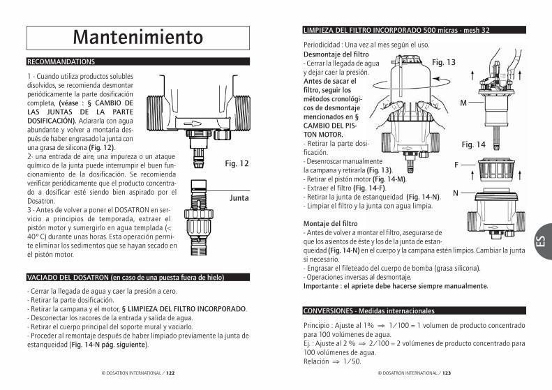
© DOSATRON INTERNATIONAL / 123
ES
© DOSATRON INTERNATIONAL / 122
Fig. 12
Junta
LIMPIEZA DEL FILTRO INCORPORADO 500 micras - mesh 32
Desmontaje del filtro- Cerrar la llegada de aguay dejar caer la presión.Antes de sacar elfiltro, seguir losmétodos cronológi-cos de desmontajemencionados en §CAMBIO DEL PIS-TON MOTOR.- Retirar la parte dosi-ficación.- Desenroscar manualmentela campana y retirarla (Fig. 13).- Retirar el pistón motor (Fig. 14-M).- Extraer el filtro (Fig. 14-F).- Retirar la junta de estanqueidad (Fig. 14-N).- Limpiar el filtro y la junta con agua limpia.
Montaje del filtro- Antes de volver a montar el filtro, asegurarse deque los asientos de éste y los de la junta de estan-queidad (Fig. 14-N) en el cuerpo y la campana estén limpios. Cambiar la juntasi necesario.- Engrasar el fileteado del cuerpo de bomba (grasa silicona).- Operaciones inversas al desmontaje.Importante : el apriete debe hacerse siempre manualmente.
CONVERSIONES - Medidas internacionales
Principio : Ajuste al 1% ⇒ 1/100 = 1 volumen de producto concentradopara 100 volúmenes de agua.Ej. : Ajuste al 2 % ⇒ 2/100 = 2 volúmenes de producto concentrado para100 volúmenes de agua.Relación ⇒ 1/50.
MantenimientoRECOMMANDATIONS
1 - Cuando utiliza productos solublesdisolvidos, se recomienda desmontarperiódicamente la parte dosificacióncompleta, (véase : § CAMBIO DELAS JUNTAS DE LA PARTEDOSIFICACIÓN). Aclararla con aguaabundante y volver a montarla des-pués de haber engrasado la junta conuna grasa de silicona (Fig. 12). 2- una entrada de aire, una impureza o un ataquequímico de la junta puede interrumpir el buen fun-cionamiento de la dosificación. Se recomiendaverificar periódicamente que el producto concentra-do a dosificar esté siendo bien aspirado por elDosatron.3 - Antes de volver a poner el DOSATRON en ser-vicio a principios de temporada, extraer elpistón motor y sumergirlo en agua templada (<40° C) durante unas horas. Esta operación permi-te eliminar los sedimentos que se hayan secado enel pistón motor.
VACIADO DEL DOSATRON (en caso de una puesta fuera de hielo)
- Cerrar la llegada de agua y caer la presión a cero.- Retirar la parte dosificación. - Retirar la campana y el motor, § LIMPIEZA DEL FILTRO INCORPORADO. - Desconectar los racores de la entrada y salida de agua.- Retirar el cuerpo principal del soporte mural y vaciarlo.- Proceder al remontaje después de haber limpiado previamente la junta deestanqueidad (Fig. 14-N pág. siguiente).
Periodicidad : Una vez al mes según el uso.
Fig. 13
Fig. 14
M
N
F

© DOSATRON INTERNATIONAL / 125© DOSATRON INTERNATIONAL / 124
ES
AJUSTE DE LA DOSIFICACIÓN (continuación)CONEXIÓN DEL TUBO DE ASPIRACIÓN
En caso de una conexión a un DOSATRON ya utilizado, consultar imperati-vamente el § PRECAUCIONES.- Desenroscar la tuerca (Fig. 15-E) colocada debajo de la parte dosificacióne introducir el tubo de aspiración en la tuerca.- Empujar a fondo el tubo en la tubuladura acanalada y enroscar la tuercamanualmente. - Para el tubo de aspiración Ø 20 (D8RV et D8R150), quitar el collarín quemantiene el tubo de aspiración (Fig. 16-C) con un destornillador. - Meter a fondo el tubo de aspiración en la contera acanalada, y volver aponer el collarín.
Modelo D8R150- Desenroscar el anillo de bloqueo (Fig. 17-B). - Enroscar o desenroscar el casquillo de ajus-te (Fig. 17-D) para situar la parte superiordel casquillo en la marca de dosificacióndeseada.- Enroscar el anillo de bloqueo (Fig. 17-B).
Nota : La cantidad de producto inyectado esproporcional a la cantidad de agua que entraen el Dosatron. 1% => 1/100, relación de100 volúmenes de agua + 1 volumen de pro-ducto inyectado.
AJUSTE DE LA DOSIFICACIÓN (sin presión)
¡ ATENCIÓN ! No utilizar herramientas.El ajuste de la dosificación ha de efec-tuarse sin presión, después dehaberse cerrado la llegada de agua.Modelo D8R- Desenroscar el anillo de bloqueo (Fig.17-B). - Enroscar o desenroscar el casquillo deajuste (Fig. 17-D) para situar la partesuperior del casquillo en la marca de dosi-ficación deseada.- Enroscar el anillo de bloqueo (Fig. 17-B).
Fig. 15
ø 12 ø 20
D8R150D8R
ø 20(opción “V”)
Fig. 16
C
E
Fig. 17
B
D
Fig. 17
B
D
CAMBIO DE LAS JUNTAS DE LA PARTE DOSIFICACIÓN (sin presión)
Periodicidad : Una vez al año.¡ CUIDADO ! No usar herramientas o utensilios metálicos
CONSEJO : Antes de cualquier desmontaje de la parte dosificación se acon-seja hacer funcionar el DOSATRON aspirando agua clara para aclarar elsistema de inyección. Esto evita cualqier riesgo de contacto con los produc-tos que pueden estar en la parte dosificación. Llevar gafas y guantes deprotección para cualquier intervención de esta naturaleza !
Fig. 18 : Apretar la pieza y la junta con elpulgar y el índice : empujar hacia el ladoopuesto para desformarlo.Fig. 19 : Acentuar la deformación paraagarrar la parte sobresaliente de la junta, yretirar ésta última fuera de su ranura.Limpiar el asiento de la junta sin herra-mientas.El remontaje se hace a mano.Es muy importante que la junta no sequede torcida porqué una vez puesta ya nohabrá estanqueidad.
Fig. 18
Fig. 19

© DOSATRON INTERNATIONAL / 127
ES
© DOSATRON INTERNATIONAL / 126
CAMBIO DE LAS JUNTAS DE LA PARTE DOSIFICACIÓN (continuación)
LIMPIEZA Y REMONTAJE DE LA VÁLVULA DE ASPIRACIÓN
Fig. 21
Fig. 22
- Cerrar la llegada de agua y dejar caer la presión.Modelo D8R- Desenroscar la tuerca (Fig. 20/21-E) y retirar el tubo de aspiración.- Para el tubo de aspiración diam 20 (opción V), destornillar con un destor-nillador el collar (Fig. 21-C) montado en el tubo de aspiración.- Destornillar y retirar la tuerca negra. (Fig. 20/21-N).- Tirar hacia abajo para sacar todo el conjunto tubo de aspiración. - Enjuagar abundantemente con agua limpia las diferentes partes, montarde nuevo siguiendo el orden del esquema (Fig. 20/21-P) y verificar que elmuelle de retorno esté activo.- Volver a montar en el orden inverso al desmontaje manualmente.
Modelo D8R150- Desenroscar el anillo de bloqueo(Fig. 22-A).- Tirar hacia abajo para sacar todoel conjunto tubo de aspiración. - Enjuagar abundantemente conagua limpia las diferentes partes,montar de nuevo siguiendo el ordendel esquema (Fig. 22-P) y verificarque el muelle de retorno esté activo.- Volver a montar en el orden inver-so al desmontaje manualmente.
N
A
N
C
P
P
P
E E
CAMBIO DE LAS JUNTAS DE LA PARTE DOSIFICACIÓN (continuación)
CAMBIO DE LAS JUNTAS DE LA PARTE DOSIFICACIÓN- Cerrar la llegada de agua y dejar caer la presión.- Desmontar el tubo de aspiración del producto, destornillar la parte dosifica-ción como descrito en el capitulo precedente y tirar hacia abajo para retirarla. - Cambiar la junta del cuerpo dosificador (Fig. 23-O) y la junta del émbolobuzo (Fig. 23-P).- Para el D8R, destornillar la tuerca de mantenimiento de la válvula de aspira-ción (Fig. 23-E) tomando cuidado para no perder los elementos de la válvula, y luego cambiar la junta tórica (Fig. 23-T) y la junta de la válvula (Fig. 23-C).- Para el D8R150, manteniendo la tuerca (Fig. 23-S), destornillar la camisa(Fig. 23-U) y tirar hacia abajo.- Volver a montar en el orden inverso al desmontaje. Nota : La regleta de dosificación (Fig. 23-L) debe estar colocada ante usted. - Atornillar el anillo de retención (Fig. 23-R) hasta el bloqueo.
Fig. 23
D8R
opción V
opción V
D8R150
O
U
PPS
L
E
CT
R
Insertar la partedosificación a
fondo. Volver lige-ramente a
izquierda y aderecha hastaque el cuerpo
dosificador se blo-que en rotación.
Fig. 20
O

© DOSATRON INTERNATIONAL / 129
ES
© DOSATRON INTERNATIONAL / 128
Denominación/Referencia
REF. / N° Serie : ................................................................................................................................EJEMPLO D8R BP V AF P H ii
Tipo de DOSATRONBP : By-pass integradoV : Productos Viscosos(200-400 cSt)Juntas dosificación :AF = PH 7-14VF = PH 1-7Color : - = Azul
P = BlancoR = RojoV = VerdeJ = AmarilloO = Naranja
H = HastelloyOtras extensiónes(especificar)
D8RVF06140745D8RVF06140745
REF. / N° Serie
CAMBIO DEL PISTON MOTOR (sin presión)
- Cerrar la llegada de agua y dejar caer la presión.- Desmontar la parte dosificación como indicado en el parágrafo preceden-te.- Desenroscar la campana manualmente (Fig. 24-C) y retirarla.- Sacar el émbolo-buzo (Fig. 24-M) tirando hacia arriba, tomando cuidadopara guiar la junta (Fig. 24-J). - Volver a montar el conjunto en el orden inverso al desmontaje.- Volver a montar la campana procurando no estropear su junta y enroscarlamanualmente.- Volver a montar el subconjunto dosificación.
Fig. 24
M
J
M
C C
D8R D8R150

© DOSATRON INTERNATIONAL / 131
ES
© DOSATRON INTERNATIONAL / 130
Posibles IncidenciasSINTOMAS CAUSA SUBSANAR
Pistón motorSu DOSATRON no Pistón bloqueado Reactivar el pistón arranca o se para accionando manualmente
Caudal excesivo 1. Reducir el caudal, volvera ponerlo en marcha
2. Controlar el montaje delas juntas de las válvu-las del motor
El by-pass está, o cer- Poner la palanca enrado, o medio abierto posición ON
Pistón motor roto. Devolver el DOSATRON asu distribuidor.
Filtro atascado Limpiar el filtro : § p19DosificaciónRetorno en el Válvula de aspiración Limpiar o cambiarrecipiente de o junta de la válvula concentrado sucia, desgastada o
ausenteNo aspira el El pistón hidráulico Véase Pistón motorconcentrado está parado
Toma de aire en el Controlar el tubo de tubo de aspiración aspiración y el apriete
de sus tuercasTubo de aspiración Limpiar o cambiarobstruido o filtro atascadoJunta de la válvula Limpiar o cambiarde aspiración desgastada, mal montada o suciaJunta del émbolo buzo Limpiar o cambiarmal montada o sucia
SINTOMAS CAUSA SUBSANAR
DosificaciónNo aspira el Grietas en el cuerpo Cambiarconcentrado mal montada o sucia
Subdosificación Toma de aire 1. Controlar el apriete delas tuercas de la partedosificación
2. Verificar el estado deltubo de aspiración
Junta de válvula de Limpiar o cambiaraspiración desgastadao sucia
Caudal excesivo Reducir el caudal
Junta del émbolo buzo Cambiardesgastada
Cuerpo dosificador Cambiarrayado
FugasFugas a proximidad Junta de la camisa Ponerla correctamente del anillo metálico estropeada, mal o cambiarde fijación bajo del montada o ausentecuerpo de bomba
Fugas entre el Junta del cuerpo Ponerla correctamente anillo de dosificador o cambiarregulación y el estropeada, malanillo de bloqueo montada o ausente
Fugas entre el Junta de la campana Ponerla correctamente, cuerpo y la estropeada, mal limpiar el asiento de campana montada o ausente la junta o cambiar
DOSATRON INTERNATIONALRECHAZA CUALQUIER RESPONSABILIDAD EN CASO DE UTILIZACIÓN
NO CONFORME CON LAS INSTRUCCIONES TÉCNICAS

© DOSATRON INTERNATIONAL / 133
ES
© DOSATRON INTERNATIONAL / 132
GarantíaDOSATRON INTERNATIONAL S.A secompromete a sustituir todo mate-rial identificado como defectuoso deorigen durante un periodo de docemeses a partir de la fecha de compradel cliente inicial.
Para obtener la sustitución bajogarantía, el equipo o repuesto deberser enviado con el comprobante decompra inicial al fabricante o al distri-buidor oficial para que sea reconocidocomo defectuoso después control porel departamento técnico del fabrican-te o distribuidor.
El equipo debe ser enjuagado paraeliminar cualquier producto químicoy enviado limpio al fabricante o dis-tribuidor ; el cliente se hará cargodel transporte. El equipo serádevuelto gratuitamente si la repara-ción se encuentra bajo garantía.
Las reparaciones realizadas bajogarantía no podrán prolongar eltiempo de la misma.
Esta garantía solo se aplica a losdefectos de fabricación.
Esta garantía no cubre los efectosderivados de una mala utilizacióndel equipo, del uso de herramientasinapropiadas, de un defecto de ins-talación o de mantenimiento, de
desastres naturales, o debido a lacorrosión causada por cuerposextraños o líquidos encontrados enel interior o cerca del equipo.
Para la dosificación de productosagresivos, le rogamos consulte eldistribuidor oficial DOSATRON antesde cualquier utilización para confir-mar la compatibilidad del productocon el dosificador.
Las garantías no comprenden lasjuntas (repuestos de desgaste) ni losdaños causados por las impurezasdel agua, como la arena.
Para dar validez a esta garantía, esimprescindible instalar un filtro(300 mesh - 60 micras o inferior)antes del equipo.
DOSATRON INTERNATIONAL SArehusa toda responsabilidad si elequipo es utilizado en condicionesno conformes a las prescripcionesdel manual de utilización.
No existe garantía, implícita o explí-cita, relativa a otros productos oaccesorios utilizados con los equiposde DOSATRON INTERNATIONAL S.A.
No dude en entrar en contacto connuestro distribuidor o con Dosatronpara cualquier servicio post-venta.
CONOCER SU CAUDAL
UN MÉTODO SENCILLOEL DOSATRON SE COMPONE :
La cadencia del motor es proporcional al caudal de agua que pasa por elaparato.
En su movimiento de vaivén, el pistón motor produce las pistónadas siguientes :
Cuente la cantidad de pistónadas del pistón en 30 segundos x 10 =Caudal de agua en litros/H.
NOTA : Este método de cálculo no reemplaza un caudalímetro.Sólo se proporciona a título orientativo.
De un motor hydráulico volumétrico depistón de accionamiento :
De un pistón dosificador.
1 vez en la posición superior
1 vez en la posición inferior

© DOSATRON INTERNATIONAL / 135
NL
© DOSATRON INTERNATIONAL / 134
Belangrijk ! Het serienummer en complete model van uw DOSATRON zijn in het pomphuis gegraveerd.Schrijf het nummer hieronder op, u heeft het nodig wanneer u uw dealer belt voor informatie, onderdelen of service.
Type: ................................................................................
Serienummer: ................................................................
Aankoopdatum: ..............................................................
Nederlands
Proficiat met de aanschaf van uw DOSATRON. U heeft een goede keuze gemaakt.De ontwikkeling van dit model is het resultaat van meer dan 30 jaar ervaring. Onzetechnici hebben de DOSATRON koploper gemaakt op het gebied van door wateraangedreven proportionele doseerpompen.Wij zijn zeer nauwkeurig te werk gegaan bij de keuze van toe te passen materialenteneinde de inwerking van de meeste te doseren chemicaliën te kunnen weerstaan Deze DOSATRON zal zich in de loop der tijd als een zeer waardevol hulpmiddelbewijzen.Regelmatig onderhoud en wat aandacht geeft u de garantie dat de DOSATRONjarenlang probleemloos zal werken.
LEES DAAROM AANDACHTIG DEZE GEBRUIKSAANWIJZING, ALVORENS
DE DOSEERPOMP AAN TE SLUITEN.
Dit document vormt geen contractuele verbintenis en wordt enkel terinformatie gegeven. Dosatron International behoudt zich het recht voorzijn toestellen op elk ogenblik zonder voorafgaande informatie te wijzigen.
© DOSATRON INTERNATIONAL S.A. 2007
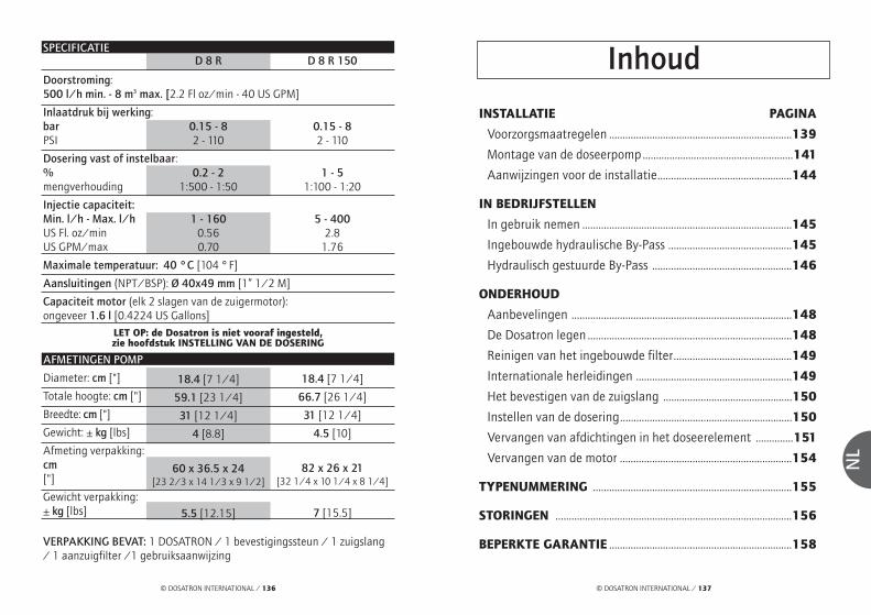
© DOSATRON INTERNATIONAL / 137
NL
© DOSATRON INTERNATIONAL / 136
INSTALLATIE PAGINA
Voorzorgsmaatregelen ....................................................................139
Montage van de doseerpomp........................................................141
Aanwijzingen voor de installatie..................................................144
IN BEDRIJFSTELLEN
In gebruik nemen ..............................................................................145
Ingebouwde hydraulische By-Pass ..............................................145
Hydraulisch gestuurde By-Pass ....................................................146
ONDERHOUD
Aanbevelingen ..................................................................................148
De Dosatron legen ............................................................................148
Reinigen van het ingebouwde filter............................................149
Internationale herleidingen ..........................................................149
Het bevestigen van de zuigslang ................................................150
Instellen van de dosering................................................................150
Vervangen van afdichtingen in het doseerelement ..............151
Vervangen van de motor ................................................................154
TYPENUMMERING ..........................................................................155
STORINGEN ........................................................................................156
BEPERKTE GARANTIE ....................................................................158
InhoudSPECIFICATIE
Doorstroming: 500 l/h min. - 8 m3 max. [2.2 Fl oz/min - 40 US GPM]
Inlaatdruk bij werking: barPSI
Dosering vast of instelbaar: %mengverhouding
Injectie capaciteit: Min. l/h - Max. l/hUS Fl. oz/minUS GPM/max
Maximale temperatuur: 40 °C [104 ° F]
Aansluitingen (NPT/BSP): Ø 40x49 mm [1” 1/2 M]
Capaciteit motor (elk 2 slagen van de zuigermotor):ongeveer 1.6 l [0.4224 US Gallons]
VERPAKKING BEVAT: 1 DOSATRON / 1 bevestigingssteun / 1 zuigslang/ 1 aanzuigfilter /1 gebruiksaanwijzing
LET OP: de Dosatron is niet vooraf ingesteld, zie hoofdstuk INSTELLING VAN DE DOSERING
0.15 - 82 - 110
0.2 - 21:500 - 1:50
1 - 1600.560.70
D 8 R
AFMETINGEN POMP
Diameter: cm ["]
Totale hoogte: cm ["]
Breedte: cm ["]
Gewicht: ± kg [lbs]
Afmeting verpakking: cm["]
Gewicht verpakking: ± kg [lbs]
18.4 [7 1/4]
59.1 [23 1/4]
31 [12 1/4]
4 [8.8]
0.15 - 82 - 110
1 - 51:100 - 1:20
5 - 4002.8
1.76
D 8 R 150
18.4 [7 1/4]
66.7 [26 1/4]
31 [12 1/4]
4.5 [10]
60 x 36.5 x 24[23 2/3 x 14 1/3 x 9 1/2]
82 x 26 x 21[32 1/4 x 10 1/4 x 8 1/4]
5.5 [12.15] 7 [15.5]

© DOSATRON INTERNATIONAL / 139
NL
© DOSATRON INTERNATIONAL / 138
InstallatieVOORZORGSMAATREGELEN
1. ALGEMENE OPMERKINGENWanneer een DOSATRON aangeslo-ten wordt op het openbarewaterleidingnet of op een eigenwatervoorziening dient men de geldende voorschriften in acht tenemen betreffende het beschermenvan de bron, zoals het voorkomenvan terugstromen etc.- In het geval dat de installatie hogeropgesteld staat dan de doseerpompzelf, bestaat de mogelijkheid dat waterterugstroomt door de pomp. Daarom ishet in deze situatie aan te bevelen eenterugslagklep achter de uitlaat van dedoseerpomp te monteren.- Installeer de pomp niet direct boveneen vat met een zuur of andere agres-sieve middelen (i.v.m opstijgendezure dampen) en bescherm hettegen mogelijk contact met corrosieveproducten.- Bescherm de DOSATRON tegenbevriezen door de pomp leeg telaten lopen en stel de pomp niet inextreme hitte op.- De DOSATRON niet aan de aanzuig-leiding van de water/aanvoerpompaansluiten (gevaar voor hevelwerking)- De gebruiker moet tijdens werkzaamheden vóór de pomp blijven en een veiligheidsbril enhandschoenen dragen.
- De eigenaar of gebruiker van depomp draagt de verantwoording omjaarlijks de injectiepakkingen/afdicht-ringen te vervangen om een exactedosering te waarborgen.- De eigenaar of gebruiker van depomp draagt de verantwoording omte controleren of de doorstroming endruk van de installatie aan de specifi-caties van de DOSATRON voldoen.- De eigenaar of gebruiker van depomp draagt de verantwoording omvast te stellen of de juiste hoeveelheidinjectievloeistof wordt opgezogen omhet gewenste resultaat te bereiken.- Lucht, een verontreiniging of che-mische aantasting van eenafdichtring/pakking kan het doserenbeïnvloeden. Het wordt aanbevolenom regelmatig te controleren of erinjectievloeistof wordt aangezogen.- Vervang de aanzuigslang zodradeze aangetast lijkt door de injectievloeistof.- laat de DOSATRON na gebruik nietonder druk staan - spoelen van de DOSATRON isgewenst:. bij het wijzigen van de injectie-vloeistof. vóór onderhoud aan de DOSATRON,teneinde contact met de injectie-vloeistof te vermijden
Exact, eenvoudig, betrouwbaar
Motor-zuiger
Water Oplossing water + %
concentraatDoseerzuiger
Instelling Dosering (%)
Te doseren concentraat
De Dosatron, aangesloten in het waternet, gebruikt de waterdrukals enige aandrijfkracht voor de motorzuiger. Deze drijft eendoseerzuiger aan, die het concentraat opzuigt in het ingesteldepercentage en het vervolgens mengt met het aandrijvende water.De aldus verkregen oplossing wordt vervolgens via de leidingenverdeeld. De geïnjecteerde hoeveelheid concentraat is ten alletijde proportioneel aan de hoeveelheid water die door de Dosatrongaat, ook als er eventuele schommelingen in de waterdruk en doorstroming in het netwerk optreden.

HET MONTAGE MAG NOOITONDER DRUK PLAATSVINDENDe DOSATRON wordt geleverd met:- Een bevestigingssteun,- Een aanzuigslang met filter.- een slang (By-Pass) ø 6 x 9 .Met de bevestigingssteun kan deDOSATRON aan de muur bevestigdworden.- Breng de zwaluwstaarten van deDosatron (Fig. 1-A) in de muursteun(Fig. 1-S).- Verwijder de moeren (Fig. 1-E) ende klemringen (Fig. 1-C) op de gatenvoor ingang en uitgang vanwater van de DOSATRON.
Verwijder de plastik doppen aan dein – en uitlaat van de DOSATRON(fig. 1-B).- Zorg voor de goede positioneringaan de ingang en aan de uitgangvan het waterdichtheidssysteem.Plaats eerst de O-ring (Fig. 1-J) endaarna de klemring (Fig. 1-G). - Zorg ervoor dat het water in derichting van de pijl op de DOSA-TRON stroomt !
MONTAGE VAN DE DOSEERPOMP
A
Fig. 1E C B G J
B
S
© DOSATRON INTERNATIONAL / 141
NL
© DOSATRON INTERNATIONAL / 140
1 - ALGEMENE OPMERKINGEN(vervolg)- Raadpleeg voor het aanzuigen vanagressieve chemicaliën uw leveran-cier, om vast te stellen of dedoseerpomp hiertegen bestand is.- Het in en uit elkaar nemen van depomp mag niet met gereedschapgebeuren, gebruik alleen handkracht.
2 - VERONTREINIGD WATER- Installeer een filter met een maas-wijdte van 60 micron - 300 mesh(afhankelijk van de waterkwaliteit)vóór de DOSATRON (zie accessoi-res). Wanneer geen filter wordtgeïnstalleerd kunnen verontreini-gingen er de oorzaak van zijn dat deDOSATRON voortijdig slijt.
3 - WATERSLAG/BUITENSPORIGEDOORSTROMING- Installaties welke onderhevig zijnaan waterslag dienen voorzien teworden van een beveiliging, zoalseen terugslagklep en/of waterslag-demper. - Bij geautomatiseerde installatiesworden langzaam openende en slui-tende magneetventielen aanbevolen.- In geautomatiseerde installatieswaarin de DOSATRON diverse sectoren bedient, dienen demagneetventielen gelijktijdig in enuit geschakeld te worden.
4 - PLAATSING EN INSTALLATIE- De plaatsing van de DOSATRON ende container met injectievloeistofmoet vrij toegankelijk zijn, maarzodanig dat vluchtige chemicaliën deinjectievloeistof niet kunnen beder-ven en geen risico tot vervuilingmeebrengen.- Het wordt aanbevolen om alle leidin-gen te voorzien van de waarschuwing: "niet voor menselijke consumptie".
5 - ONDERHOUD- Spoel de DOSATRON na gebruikdoor. Hang de aanzuigslang in eenemmer met schoon lauw water enzuig ongeveer een (1/4 liter op[8 1/2 US Fl.oz]).- Regelmatig onderhoud, minimaaleens per jaar, zal de levensduur vanuw DOSATRON verlengen. Vervangde doseerpakkingen/afdichtringenen de aanzuigslang minstens éénmaal per jaar om u van een juistedosering te verzekeren.
6 - SERVICE- Elke DOSATRON wordt voor hetinpakken in de fabriek getest.- Complete onderhoud- en pakkingsetszijn verkrijgbaar.- Bel uw leverancier of Dosatron voorservice of onderdelen.
AANBEVELINGEN ( vervolg)

© DOSATRON INTERNATIONAL / 143
NL
© DOSATRON INTERNATIONAL / 142
BELANGRIJK – Het filter moet minimaal 10cm boven de bodem van hetvooraadvat hangen om te voorkomen dat onopgeloste deeltjes in depomp gezogen worden en deze beschadigen (Fig. 3).- De zuigfilter niet op de bodem zetten.
LET OP: De maximum aanzuighoogte is 4 meter [13 ft].
- Het filter met zuigslang aansluiten en in de injectievloeistof hangen.
Het niveau van de injectievloeistof mag om hevelwerking te voorkomennooit boven de inlaat van de DOSATRON uitkomen.
MONTAGE VAN DE DOSEERPOMP (vervolg)
10 c
m
Fig. 3
ZO MOET HET NIET
ZO MOET HET
▼
▼
Fig. 4
De te volgen methode voor aans-luiting met een buis in PVC : - Ga te werk zoals voor de aansluitingmet een buis in polyethyleen of poly-propyleen, maar vooraleer vast tedraaien, smeer de plaats die de klem-ring zal bekleden met PVC-lijm. - De klemring naar voren in positiebrengen, door hem uiteen te schui-ven met de twee duimen in de gleufgeplaatst (Fig. 2-C) om de lijm niet afte schrapen, en daarna de moer vast-draaien.
NOTA : een uur wachten vooraleerhet circuit onder druk te zetten. Voorelke latere demontage, moet menweten dat de PVC-lijm niet kleeft aande klemring, die in polyacetal is.
De aansluiting van het toestel op het waternet kan gebeuren met behulpvan de soepele slangen van 40 mm binnendiameter bevestigd met beugelsen draaiende verbindingsstukken met moeren Ø 40 x 49 mm (1"1/2). Zorgervoor dat het water loopt in de richting van de pijlen op het toestel.
De DOSATRON wordt met een aanzuigslang van 1,2m geleverd, waardoorhij in combinatie met een groot voorraadvat gebruikt kan worden (indiengewenst op lengte afsnijden). Het bijgeleverde filter en contragewicht moetaan de zuigslang bevestigd worden.
MONTAGE VAN DE DOSEERPOMP (vervolg)
De te volgen methode voor aan-sluiting met buis in polyethyleenof polypropyleen :- Plaats de moer (Fig. 2-E) en deklemring (Fig. 2-C) op de buis vooringang en uitgang van water, juistafgesneden en afgekant. - Steek de buis tot tegen de aanslagin de gaten voor ingang en uitgangvan water (Fig. 2).- Duw de klemring (Fig. 2-C) tot tegende aanslag op de ingang, en daarnade andere op de wateruitgang. - De moer vastdraaien (Fig. 2-E).
E
Fig. 2
C

- De hendel van de By-Pass (Fig. 7-L)op positie ON zetten. - Open nu de wateraanvoer helemaal,de DOSATRON is zelfaanzuigend.- Laat de DOSATRON werken totdat de injectievloei-stof in de doseerbuisopgezogen is (de injectievloeistof is door de heldere zuigslang te zien).- De DOSATRON maakt een karakteristiek klikkend geluid wanneer hij in bedrijf is. NOTA: De tijd welke nodig is om de zuigslang te vullen is afhankelijk vande doorstroming, de ingestelde dosering en de lengte van de zuigslang. Omde lucht zo snel mogelijk uit de zuigslang te krijgen en het aanzuigen teversnellen moet de dosering op maximum gezet worden. Zodra de vloeistofaangezogen is kan de dosering op de gewenste stand ingesteld worden(zie § INSTELLEN VAN DE DOSERING).
Fig. 7F
© DOSATRON INTERNATIONAL / 145
NL
© DOSATRON INTERNATIONAL / 144
Het in bedrijf stellen van de DOSATRON
IN GEBRUIK NEMEN (voor de eerste keer)
Systeem om aanzuiging van product in gang te zetten of stop te zetten: Een druk van minimaal 0.8 bar van aandrijfwater is noodzakelijk om eengoede werking van de By-Pass te verkrijgen.- By-pass op OFF (Fig. 8-L), de DOSATRON staat uit en de injectievloeistofwordt niet opgezogen.- By-pass op ON (Fig. 9-L), de DOSATRON is in bedrijf en de injectievloeistofwordt opgezogen.
OPGEPAST! Wanneer men van de stand OFF overgaat naar de stand ON,is het normaal dat een kleine hoeveelheid water ontsnapt langs degeribbelde staart Ø 3 [1/8”] (Fig. 9-Q).
AANWIJZINGEN VOOR DE INSTALLATIE
Te hoge doorstroming (indicatie)Wanneer uw DOSATRON meer dan 40 keer, d.w.z. 20 cyclussen per 15 secondentikt, ligt de doorstroming dicht bij de maximum grens. Wanneer u meer doorstro-ming heeft, moet u een DOSATRON met een grotere capaciteit installeren.
De DOSATRON kan direct (fig. 5) ofvia een bypass (fig. 6) in de waterlei-ding geïnstalleerd worden.
Om de levensduur van de DOSATRONte verlengen wordt geadviseerd eenfilter van ( 300 mesh = 60 micronafhankelijk van de waterkwaliteit)voor de DOSATRON te installeren. Ditis noodzakelijk wanneer het waterverontreinigingen bevat of vastedeeltjes, speciaal bij water uit eeneigen bron.Een filter wordt aanbevolenen is nodig om voor garan-tie in aanmerking te komen.
De installatie van een DOSATRON ineen bypass geeft de mogelijkheidom over schoon water te beschikkenterwijl de DOSATRON in onderhoudis of gerepareerd wordt.
Voor elke installatie geldt datdeze moet voldoen aan deeisen van het plaatselijke
waterleidingbedrijf.
terugslagklep
KraanKraan
Filter Filter
Fig. 6Fig. 5
Fig. 8 Fig. 9
L L Q
INGEBOUWDE HYDRAULISCHE BY-PASS

© DOSATRON INTERNATIONAL / 147
NL
© DOSATRON INTERNATIONAL / 146
HYDRAULISCH BESTUURDE BY-PASS
Systeem om aanzuiging van product in gang te zetten of stop te zetten: Een druk van minimaal 0.8 bar van aandrijfwater is noodzakelijk om eengoede werking van de By-Pass te verkrijgen.NOTA : Bij gebruik van de By-Pass met afstandsbediening, moet de manue-le bedieningshendel (Fig. 10-L) zich in de stand ON bevinden.
HYDRAULISCH BESTUURDE BY-PASS (vervolg)
Automatische uitrusting anti-overheveling van het product: - Het herstelt automatisch de atmosferische druk in de installatie in gevalvan accidentele depressie* (Fig. 11). Zijn gebruik is onderhevig aan de sani-taire reglementering die in het land van kracht is. - De voorziene bepalingen naleven.- Om het in werking te zetten, de moer losdraaien (Fig. 11-E), het volle meta-len ringetje verwijderen (Fig. 11-P) en die vervangen door het holle ringetje(Fig. 11-C) die in het pak zit. - De moer opnieuw vastdraaien (Fig. 11-E).
Gebruik van By-Pass met afstandsbediening: - Opening van het magneetventiel. NO (Normaal Open) : 1 naar 2 > Gebruik: Aankomst aandrijfwater van de
By-Pass. Gebruik van de By-Pass (stopzetting van deDOSATRON) 3 > Gesloten uitlaat
In werking zetten van de DOSATRON: - Sluiting van het magneetventiel. NF (Normaal Gesloten) : 2 naar 3 > Uitlaat - uitlaat aandrijfwater naar
buiten. In werking zetten van de Dosatron 1 > druk in afwachting
Fig. 10
Fig. 11
F
C
E
Kogel
Rubberenringetje
P
F
Q: geribbelde staart Ø 3 [1/8"] (geleverd met de DOSATRON)
Aandrijfvloeistof (lucht ofwater) Druk: van 0,8 tot 8 bar
O: magneetventiel met 3 wegen in L
(niet geleverd met de DOSATRON)
T: soepele slang Ø 6 x 9[1/4" ID] x [3/8" OD]
*voorbeeld: geval waarbij de uitgang van het doseerapparaat lager is dande ingang.

© DOSATRON INTERNATIONAL / 149
NL
© DOSATRON INTERNATIONAL / 148
Fig. 12
afdichting
REINIGEN VAN HET INGEBOUWDE FILTER 500 microns - 32 mesh
Demontage van het filter- Sluit de kraan aan deinlaatzijde en laat dedruk wegvallen.Om vrij toegang tothet filter te verkrijgen,eerst doseerelementdemonteren, zie §VERVANGEN VANDE MOTOR.- Verwijder de zuigervan de afdichtingen inhet doseerelement.- Schroef het bovenhuis van dedoseerpomp met de hand los (Fig. 13).- Verwijder de zuiger van de motor (Fig. 14-M).- Verwijder het filter (Fig. 14-F).- Verwijder de pakking (Fig. 14-N).- Reinig het filter en de pakking met schoonwater.
Montage van het filter- Vóór de montage, erop letten dat het filter, de pakking en de raakvlakkenmet het onder- en bovenhuis (Fig. 14-N) schoon zijn. Pakking vervangenindien nodig.- De schroefdraad van het pomphuis invetten (siliconenvet). - Ga verder in omgekeerde volgorde te werk.Belangrijk: in alle gevallen moet het aandraaien met de hand gebeuren.
INTERNATIONALE HERLEIDINGEN
Uitgangspunt: instelling op 1% ⇒ 1/100 = 1 deel injectievloeistof in 100delen water.bv.: instelling op 2% ⇒ 2/100 = 2 delen concentraat in 100 delen waterVerhouding ⇒ 1/50
OnderhoudAANBEVELINGEN
1 - Bij gebruik van producten zoals poe-ders die opgelost moeten worden, is hetaan te bevelen het gehele doseerele-ment periodiek uit elkaar te nemen (zie§ VERWISSELEN VAN DE AFDICHT-RINGEN IN HET INJECTIEDEEL). Spoel al de onderdelen uit het doseere-lement grondig met water schoon en zetde delen weer in elkaar. Smeer indien nodig deafdichting (fig. 12) met siliconen smeermiddel wanneerde zuigbuis zich moeilijk laat monteren. 2 - Een luchtaanvoer, een onzuiverheid of een chemi-sche aanval van de dichting kunnen de goede werkingvan de dosering onderbreken. Het is aan te bevelenregelmatig te controleren of het te doseren gecon-centreerde product wel goed aangezogen wordtde Dosatron. 3 - Wanneer men de DOSATRON een tijd nietgebruikt heeft, is het aan te raden de zuigermotoreen paar uur in lauw warm water <40°C te latenweken. Dit helpt om opgedroogd vuil en uitgekris-talliseerd concentraat los te weken.
DE DOSATRON LEGEN (Bij vorstgevaar)
- Sluit de kraan aan de inlaatzijde en laat de druk wegvallen.- Verwijder het doseerelement.- Verwijder het schroefdeksel en de zuigermotor, § REINIGEN VAN HETINGEBOUWDE FILTER. - Maak de koppelingen aan aan- en afvoer los.- Haal het pomphuis uit de steun, en verwijder het laatste water.- De DOSATRON kan nu weer in elkaar gezet worden, (eerst dekselpakkingschoonmaken fig.14-N).
Ter indicatie : één keer per maand afhankelijk van de toepassing.
Fig. 13
Fig. 14
M
N
F

© DOSATRON INTERNATIONAL / 151© DOSATRON INTERNATIONAL / 150
NL
INSTELLEN VAN DE DOSERING (vervolg)HET BEVESTIGEN VAN DE ZUIGSLANG
Wanneer de DOSATRON al eens gebruikt is lees dan eerst op § VOOR-ZORGSMAATREGELEN.- Draai de slangwartelmoer (Fig. 15-E) onder aan de zuigbuis los en schuifhem over de zuigslang.- Duw de zuigslang zo ver mogelijk over de slangpilaar, en draai de wartel-moer met de hand aan.- Voor de aanzuigslang Ø 20 (D8RV et D8R150), met een schroevendraaierde ring (Fig. 16-C) losdraaien.- Duw de zuigslang zo ver mogelijk over de slangpilaar, en de ring met deschroevendraaier weer vastdraaien.
Model D8R150- Draai de conische moer/blokkeerring los(Fig. 17-B).- Draai de doseermoer links- of rechtsom (Fig.17-D) totdat de bovenzijde correspondeertmet de gewenste doseerwaarde.- Draai de blokkeerring weer vast (Fig. 17-B).
HERINNERING: De hoeveelheid opgenomenproduct is evenredig met de hoeveelheidwater die in de Dosatron komt. 1% ⇒1/100, verhouding van 100 volumes water +1 volume van het ingespoten product.
INSTELLEN VAN DE DOSERING (pomp niet onder druk)
BELANGRIJK ! geen gereedschap gebrui-ken. Het instellen van de dosering magnooit onder druk plaatsvinden. Sluitde kraan aan de inlaatzijde en laatde drukwegvallen.Model D8R- Draai de conische moer/blokkeerring los (Fig. 17-B).- Draai de doseermoer links- of rechtsom(Fig. 17-D) totdat de bovenzijde corres-pondeert met de gewenste doseerwaarde.- Draai de blokkeerring weer vast (Fig. 17-B).
Fig. 15
ø 12 ø 20
D8R150D8R
ø 20(optie “V”)
Fig. 16
C
E
Fig. 17
B
D
Fig. 17
B
D
VERVANGEN VAN DE AFDICHTINGEN IN HET DOSEERELEMENT (pomp niet onder druk)
Frequentie: minstens éénmaal per jaar.BELANGRIJK ! Draag tijdens deze werkzaamheden altijd beschermendekleding, veiligheidsbril en handschoenen. Gebruik geen gereedschap!ADVIES: Alvorens het doseerelement uit elkaar te nemen, verdient het aanbe-veling om de DOSATRON schoon water op te laten zuigen en zodoende hetdoseerelement door te spoelen. Daardoor wordt het risico van contact metinjectievloeistoffen verkleind ! METHODE VOOR HET VERWIJDERENVAN DE AFDICHTRINGFig. 18 : knijp met vinger en duim in deafdichtring, en duw deze naar een kant.Fig. 19 : verhoog de vervorming van dering nog meer totdat deze uit-steekt enuit zijn zitting getrokken kan worden.Maak de zitting van de ring schoon (geengereedschap gebruiken). Terugplaatsenwordt met de hand gedaan. Het is zeerbelangrijk dat de afdichtingring nietgedraaid in de zitting komt te liggen,omdat hij anders niet goed afdicht.
Fig. 18
Fig. 19

Fig. 23
D8R
optie Voptie V
D8R150
O
U
PPS
L
E
CT
R
Breng het doseer-deel volledig
tegen de aanslag.Lichtjes naarrechts of naar
links draaien tothet doseerlichaamblokkeert bij het
draaien.
O
© DOSATRON INTERNATIONAL / 153
NL
© DOSATRON INTERNATIONAL / 152
VERVANGEN VAN DE AFDICHTINGEN IN HET DOSEERELEMENT (vervolg)
REINIGING EN MONTAGE VAN DE TERUGSLAGKLEP
Fig. 21
Fig. 22
- Draai de watertoevoer uit en laat de druk naar nul zakken.Model D8R- Draai de witte moer (Fig. 20/21-E) los en verwijder de zuigslang.- Voor de aanzuigslang Ø 20 (D8RV et D8R150), met een schroevendraaierde ring (Fig. 21-C) losdraaien.- De zwarte moer (Fig.20/21-N) losdraaien en verwijderen. - Trek het zuigventiel naar beneden uit de zuigbuis.- De verschillende delen met proper water overvloedig spoelen, ze opnieuwmonteren in de volgorde van het schema (Fig. 20/21-P) en controleren ofde terugstelveer wel degelijk actief is.-Plaats de verschillende onderdelen in omgekeerde volgorde met de hand terug.
Model D8R150- Draai de conische moer/blokkeerring los (Fig. 22-A).- Trek het zuigventiel naar beneden uitde zuigbuis.- De verschillende delen met properwater overvloedig spoelen, ze opnieuwmonteren in de volgorde van het sche-ma (Fig. 22-P) en controleren of deterugstelveer wel degelijk actief is. -Plaats de verschillende onderdelen inomgekeerde volgorde met de hand terug.
N
A
N
C
P
P
P
E E
VERVANGEN VAN DE AFDICHTINGEN IN HET DOSEERELEMENT (vervolg)
VERVANGEN VAN DE TERUGSLAGKLEPPAKKING- Draai de watertoevoer uit en laat de druk naar nul zakken.- De aanzuigslang van het product demonteren, het deel dosering los-draaien zoals beschreven in vorige paragraaf en naar beneden trekken omhet te verwijderen.- De pakking van de zuigbuis (Fig. 23-O) en die van de doseerzuiger (Fig.23-P) veranderen.- Voor de D8R, de moer van de aanzuigklep (Fig. 23-E) losdraaien, en zorgervoor de elementen van de klep niet te verliezen, daarna de O-ring vervan-gen (Fig. 23-T) en de pakking van de klep (Fig. 23-C).- Voor de D8R150, terwijl u de moer (Fig. 23-S) op zijn plaats houdt, draai hetomhulsel van het doseerapparaat los (Fig. 23-U) en naar beneden trekken.-Plaats de verschillende onderdelen in omgekeerde volgorde met de hand terug. Nota: de doseerschaal (Fig. 23-L) moet tegenover u in positie gebracht worden. - De vasthoudmoer (Fig. 23-R) draaien tot blokkering.
Fig. 20

© DOSATRON INTERNATIONAL / 155
NL
© DOSATRON INTERNATIONAL / 154
Typenummering
REF. /Serie # : ..................................................................................................................................VOORBEELD D8R BP V AF P H ii
Type DOSATRONBP : geïntegreerde bypassV : viskeuze producten(200-400 cSt)Pakkingen/afdichtringen :AF = PH 7-14VF = PH 1-7Kleur: - = blauw
P = witR = roodV = groenJ = geelO = Oranje
H = HastelloyAndere letters(raadpleeg ons)
D8RVF06140745D8RVF06140745
REF. / Serie #
VERVANGEN VAN DE MOTOR (pomp niet onder druk)
- Draai de watertoevoer uit en laat de druk naar nul zakken. - Het doseergedeelte demonteren zoals uitgelegd in vorige paragraaf. - Draai het bovenhuis met de hand los (Fig. 24-C).- Trek de motorzuiger naar boven uit het huis (Fig. 24-M), en zorg er daarbijvoor om de pakking te leiden (Fig. 24-J). - Verwissel de motorzuiger en zet alles in omgekeerde volgorde weer in elkaar.- Draai het bovenhuis weer met de hand vast (let op dat de afdichtring nietbeschadigd wordt).- Doseerelement weer op zijn plaats brengen en vastdraaien.
Fig. 24
M
J
M
C C
D8R D8R150

© DOSATRON INTERNATIONAL / 157
NL
© DOSATRON INTERNATIONAL / 156
StoringenPROBLEEM OORZAAK OPLOSSING
ZuigermotorDOSATRON start Zuigermotor loopt Reset de zuiger met deniet of stopt niet hand
Maximum 1. verlaag de doorstroming,doorstroming herstart de pompoverschreden 2. Draai het bovenhuis los,
verwijder de zuiger encontroleer of de zuiger-klepringen nog op hunplaats zitten
De by-pass staat op De by-pass op ON OFF, ofwel halfopen zetten
Zuigermotor Stuur de pomp naar uwbeschadigd servicecentrum terug
Filter verstopt Filter reinigen: § p149DoseringWater stroomt terug Vervuilde, versleten Reinigen of vervangenin de concentraat ontbrekende delen oftank van de terugslagklep
Er wordt geen con- De zuigermotor is Zie bij zuigermotorcentraat opgezogen gestopt
Lekke aanzuigslang Vervang aanzuigslang
Verstopte zuigslang Reinigen of vervangenof aanzuigfilter
Ontbreken of versleten Reinigen of vervangenterugslagkleppakking
Ontbreken of versleten Vervangenaanzuigpakking
Versleten zuigbuis Vervangen
PROBLEEM OORZAAK OPLOSSING
DoseringTe lage dosering Er wordt lucht 1. controleer of de moeren
aangezogen van het doseerelement aangedraaid zijn
2. controleer de aanzuigslang reinigen of vervangen
Vervuilde of versleten Verlaag de doorstromingterugslagkleppakking
Overschrijding van de Verlaag de doorstromingmaximale doorstro-ming (cavitatie)
Versleten Vervangenaanzuigpakking
Versleten zuigbuis Vervangen
LekkenLekkage bij de aan- Doseerhulsring Juist plaatsen ofsluiting doseerbuis beschadigd of onjuist vervangenpomphuis geplaatst
Lekkage tussen de Zuigbuisring Vervangendoseermoer en de beschadigd onjuistblokkeerring geplaatst of onbreekt
Lekkage tussen het Pakking tussen boven- Schroef het bovenhuis los, boven- en onderhuis en onderhuis is reinig de pakkingzitting,
beschadigd, onjuist nieuwe pakking of oude geplaatst of onbreekt zorgvuldig terugleggen
DE FABRIKANTWIJST ELKE VERANTWOORDELIJKHEID AF WANNEER
DE DOSATRON NIET VOLGENS DE AANWIJZINGEN UIT DEZE HANDLEIDING
GEBRUIKT WORDT

© DOSATRON INTERNATIONAL / 159
NL
© DOSATRON INTERNATIONAL / 158
Beperkte GarantieDOSATRON INTERNATIONAL S.A. zal gedu-rende een periode van twaalf maanden nade datum van aankoop door de oorspronke-lijke koper voorzien in de vervanging van alleonderdelen die qua materiaal of uitvoeringgebreken vertonen. Teneinde uit hoofde vandeze garantie aanspraak te kunnen makenop vervanging van een onderdeel, moet deDOSATRON aan de fabrikant of erkende dis-tributeur worden geretourneerd met hetoriginele bewijs van aankoop en vervolgensals defect worden aangemerkt na onderzoekdoor de technische dienst van de fabrikant ofde distributeur. De DOSATRON moet wordenontdaan van alle chemicaliën en vervolgens,na betaling van de verzendkosten, aan defabrikant of distributeur worden gezonden.Zodra de reparatie is uitgevoerd, zal deDOSATRON kosteloos worden geretour-neerd indien deze blijkt te worden gedektdoor deze garantie. Reparaties die wordenuitgevoerd uit hoofde van deze garantie,brengen geen verlenging van de oorspron-kelijke garantieperiode met zich mee.Alvorens agressieve chemicaliën te gebrui-ken, verzoeken wij u uw distributeur teraadplegen om te bevestigen dat de dose-ringspomp bestand is tegen deze stoffen.Deze garantie dekt slechts omstandighedenwaarbij het onderdeel defect is geraakt van-wege gebreken veroorzaakt door hetproductieproces. Deze garantie geldt nietindien de gebreken blijken te zijn veroor-zaakt door verkeerd gebruik van hetproduct, onjuist gebruik van gereedschap-pen, gebrekkig onderhoud, ondeugdelijkeinstallatie, milieuongevallen of corrosiedoor vreemde lichamen en vloeistoffen die
worden gevonden in of in de nabijheid vande DOSATRON. Noch de pakkingen en “O”-ringen, noch schade aan de DOSATRON dieis veroorzaakt door waterverontreinigingenzoals zand worden gedekt door deze garan-tie. De garantie geldt slechts indien eenfilter (300 mesh - 60 micron afhankelijk vanuw waterkwaliteit) wordt gebruikt vóór deDOSATRON. DOSATRON INTERNATIONALS.A. wijst iedere aansprakelijkheid af indiende DOSATRON niet wordt gebruikt conformde bedieningsvoorschriften en –toleranties,zoals hierin aangegeven.Deze garantie geeft u specifieke juridischerechten en u kunt tevens andere rechtenhebben die van land tot land ver-schillen.Echter, iedere stilzwijgende garantie ofverhandelbaarheid of geschiktheid vooreen bepaald doel van toepassing op ditproduct, is qua duur beperkt tot de periodeaangegeven in deze schriftelijke garantieof enige stilzwijgende garantie.Er geldt geen garantie, uitdrukkelijk ofstilzwijgend, voor producten die wordengebruikt in samenhang met producten vanDOSATRON INTERNATIONAL S.A.De fabrikant of erkende distributeur is nietaansprakelijk voor bijkomende of gevolg-schade, zoals eventuele economischeschade die het gevolg is van inbreuk opdeze schriftelijke garantie of een eventue-le stilzwijgende garantie.Er zijn geen uitgebreidere garanties, uit-drukkelijk of stilzwijgend, dan dehierboven beschreven garanties.Aarzel niet om met uw dealer of Dosatroncontact op te nemen voor service na verkoop.
WAT IS DE DOORSTROMING ?
EEN EENVOUDIGE METHODEDE DOSATRON BESTAAT UIT:
Het toerental van de zuigermotor is evenredig met de doorstroming in hetapparaat. Hoe hoger de doorstroming hoe sneller de pomp loopt.De op- en neergaande beweging van de zuigermotor geeft een klikkendgeluid:
Tel het aantal klikken in 30 seconden x 10 = Doorstroming in liters water/uur.
NOTA: Deze methode is niet zo nauwkeurig dat ze een doorstroommeter kanvervangen. Het geeft de doorstroming slechts bij benadering weer.
Een wateraangedreven zuigermotordoe gekoppeld is aan
De doseerzuiger
Eén klik in de bovenste stand
Eén klik in de onderste stand

© DOSATRON INTERNATIONAL / 161© DOSATRON INTERNATIONAL / 160
Courbes de pertes de chargesPressure loss curvesDruckverluste-DiagrammCurva di perdita di caricoCurvas de perdidas de cargaDrukverlies Grafiek............................................162
ÉclatésParts diagramSchemataSchemaEsquemasOnderdelen schemas............................................164
AnnexesEnclosure
AnhangAnejos
AllegatiBijvoegsel

D 8 R
Perdite di carico - Perdidas de carga - Drukverlies > in Bar (kgf/cm2)
-Pr
essi
on -
Pres
sure
Dru
ck -
Pres
sion
e - P
resi
ón -
Dru
k 6
Bar [
85 P
SI]
-Sa
ns c
ontr
e-pr
essi
on -
With
out p
ress
ure
- Ohn
e D
ruck
- Se
nza
cont
ro-p
ress
ione
- Sin
con
tra-
pres
ión
- Dru
kloo
s
Déb
it - W
ater
flow
rate
- D
urch
satz
> in
GPM
Port
ata
- Cau
dal -
Doo
rstr
omin
g>
in l/
h - l
/St
d - l
/u
Pertes de charges - Pressure loss - Druckverlust > in PSI
D 8 R 150
© DOSATRON INTERNATIONAL / 163© DOSATRON INTERNATIONAL / 162
Perdite di carico - Perdidas de carga - Drukverlies > in Bar (kgf/cm2)
Déb
it - W
ater
flow
rate
- D
urch
satz
> in
GPM
Port
ata
- Cau
dal -
Doo
rstr
omin
g>
in l/
h - l
/St
d - l
/u
Pertes de charges - Pressure loss - Druckverlust > in PSI
-Pr
essi
on -
Pres
sure
Dru
ck -
Pres
sion
e - P
resi
ón -
Dru
k 6
Bar [
85 P
SI]
-Sa
ns c
ontr
e-pr
essi
on -
With
out p
ress
ure
- Ohn
e D
ruck
- Se
nza
cont
ro-p
ress
ione
- Si
n c
ontr
a-pr
esió
n - D
rukl
oos

© DOSATRON INTERNATIONAL / 165© DOSATRON INTERNATIONAL / 164
D 8 R
D8R
D8R
/110
6/U
1©
DO
SA
TR
ON
INT
ER
NA
TIO
NA
L S
.A. 2
007
8 m3/h - 0.2 - 2%40 GPM - 1:500 - 1:50
0.15 - 8 bar2.2 - 116 psi
8MP
003
MP
222
MP
DI0
13
8PC001
8J01
5
8PJ0
45
8EQ001 (OPTION)
8P044
(x 4)
8MP
035
8PJ0
498P
J050
8PJ0
50II
OP
TIO
NS
12 20
8CD
032
( 1
2) +
8C
D03
2II(
12
)8C
D03
2V (
2
0)D8R
D8R
/110
6/U
2
8 m3/h - 0.2 - 2%40 GPM - 1:500 - 1:50
0.15 - 8 bar2.2 - 116 psi3
8CD
023
( 1
2) +
8C
D02
3II (
12
)8C
D02
3V (
2
0)
12 20
© D
OS
AT
RO
N IN
TE
RN
AT
ION
AL
S.A
. 200
7 12 20
8PJ0
52 (
1
2)8P
J052
V (
2
0)

© DOSATRON INTERNATIONAL / 167© DOSATRON INTERNATIONAL / 166
D 8 R 150
D8R150
D8R
150/
1106
/U1
© D
OS
AT
RO
N IN
TE
RN
AT
ION
AL
S.A
. 200
7
8 m3/h - 1 - 5%40 GPM - 1:100 - 1:20
0.15 - 8 bar2.2 - 116 psi
8MP
003
MP
DI1
35
8PC004
8J01
5
8PJ0
45
8EQ001 (OPTION)
8P044
(x 4)
8MP
030
8CD
026
8PJ0
498P
J050
8PJ0
50II
OP
TIO
NS
D8R150
D8R
150/
1106
/U2
8 m3/h - 1 - 5%40 GPM - 1:100 - 1:20
0.15 - 8 bar2.2 - 116 psi
8PJ0
57
8CD
026
8PJ0
54
( 20)
© D
OS
AT
RO
N IN
TE
RN
AT
ION
AL
S.A
. 200
7
Ce document ne constitue pas un engagement contractuel et n’est fourni qu’à titre indicatif.La Société DOSATRON INTERNATIONAL se réserve le droit de modifier ses appareils à tout moment.
This document does not form a contractual engagement on the part of DOSATRON INTERNATIONAL and is for information only.The company DOSATRON INTERNATIONAL reserves the rightto alter product specification or appearance without prior notice.
Dieses Dokument ist kein bindender Vertragsbestandteil und dient nur zu Informationszwecken. Das Unternehmen DOSATRON INTERNATIONAL behält sich das Recht vor, seine Geräte jederzeit zu verändern.
Questo documento non costituisce un documento contrattuale e viene fornito soltanto a titolo indicativo.La società DOSATRON INTERNATIONAL si riserva il diritto di modificare i propri apparecchi in qualsiasi momento.
Este documento no constituye un compromiso contractualy se suministra solamente a título orientativo.La sociedad DOSATRON INTERNATIONAL se reserva el derechode modificar sus aparatos en cualquier momento.
Dit document vormt geen contractuele verbintenis en wordt enkel ter informatie gegeven. DOSATRON INTERNATIONAL behoudt zich het recht voor zijn toestellen op elk ogenblik zonder voorafgaande informatie te wijzigen.
CE Conformity StatementDocument N° DOCE05050108 This Dosatron is in compliance with the EuropeanDirective 98/37/CEE. This declaration is only valid forcountries of the European Community (CE).

DOSATRON INTERNATIONAL S.A.
Rue Pascal - B.P. 6 - 33370 TRESSES (BORDEAUX) - FRANCETel. 33 (0)5 57 97 11 11Fax. 33 (0)5 57 97 11 29 / 33 (0)5 57 97 10 85e.mail : [email protected] - http://www.dosatron.com
FABRIQUÉ PARMANUFACTURED BYHERGESTELLT VONFABBRICATO DAFABRICADO PORGEPRODUCEERD DOOR
ISO 9001 : 2000 Quality System Certified
NT
/ 8
/03
/07
© DOSATRON INTERNATIONAL S.A. 2006