manual bsl100 - evc · bsl100 manual ... probe, then create a project in winols (or choose “read...
TRANSCRIPT

Manual
BSL100Bootstrap Loader Module for Infineon Tricore™
Microcontrollers

EVC electronic GmbH -2- BSL100 Manual
Table of Contents
Theme: Page:
Important ........................................................................................................ 3Disclaimer/ Warranty ..................................................................................... 3The BSL100-Module....................................................................................... 4BSL130 Probe ................................................................................................ 5BSL131 Programming Adapter ..................................................................... 6BSL132 Probe ................................................................................................ 7BSL-ADP ......................................................................................................... 8BSL-DRV ......................................................................................................... 9BSL100 Manual .............................................................................................10
EVC electronic GmbHAm Pfauenzehnt 11a
46539 Dinslakenwww.evc.de

EVC electronic GmbH -3- BSL100 Manual
Important
This quick manual is intended to introduce the currently existing BSL components from EVC. Acontinuously updated list of cars which can be programmed with the BSL tools can be foundfollowing this link:
http://www.evc.de/en/product/bsl/type.asp
Additionally, a continuously updated list of ECUs which can be programmed with the BSL tools canbe found following this link.
http://www.evc.de/en/product/bsl/ecu.asp
Disclaimer / Warranty
The BSL100 module is for use by qualified personnel only. A warranty on our part for directdamages and consequential damages, caused by the improper handling of our product oradditional products is excluded.
To avoid damages on your BSL100-module or on an ECU, please carefully read this manualbefore you start running the BSL100 Module with an ECU!

EVC electronic GmbH -4- BSL100 Manual
The BSL100 Module
Pict. 1: A typical arrangement on BOSCH ECUs: BSL100 module, BSL130 probe and bootpin-probe.
Please first connect your BSL100 modulewith your PC or notebook via the USBcable.The lower of the both blue LEDs on thefront panel now starts flashing.
The BSL100 module has no own powersource. It is an USB device and obtainsIts power via the USB cable.
If the BSL100 module is connected to anECU, the upper of the both blue LEDsindicates that a data transfer is inprogress.
Pict 2: The BSL-module is always connected to theUSB cable first.
Pict. 3: The BSL100 has etablished a data connec-tion to an ECU.

EVC electronic GmbH -5- BSL100 Manual
BSL130 Probe
To force the microcontroller to CAN bootmode, it is necessary to contact one ormore special points on the board with thebootpin probe.
Therefore the bootpin probe is connectedto the 2-mm socket on the BSL130 probe(pict.1).The BSL130 probe is shipped 12V powersupply which also powers the ECU.
The switching of the power is controlledby the BSL100 module.A red LED on top of the BSL130 lightsup, indicating the ECU receives power.
Picture 2 shows the pin out of the 2 x 7pad array.
Both the CAN bus lines and also thepower for the ECU are routed from here.The extra pads of this array are not used.
On Bosch ECUs the 2 x 7 pad arraycommonly is located near the border ofthe board.
Pict.1: The BSL130 probe is lowered to the pad arrayand the bootpin probe is placed on the bootpin.
Pict 2: The pin out of the 2 x 7 pad array.
EVC electronic GmbH -6- BSL100 Manual
BSL131 Programming Adapter
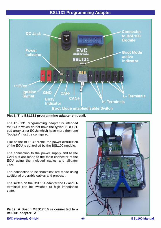
Pict 1: The BSL131 programming adapter en detail.
The BSL131 programming adapter is intendedfor ECUs which do not have the typical BOSCH-pad array or for ECUs which have more then one"bootpin" must be configured.
Like on the BSL130 probe, the power distributionof the ECU is controlled by the BSL100 module.
The connection to the power supply and to theCAN bus are made to the main connector of theECU using the included cables and alligatorclips.
The connection to he "bootpins" are made usingadditional orderable cables and probes. .
The switch on the BSL131 adapter the L- and H-terminals can be switched to high impedancestate.
Pict.2: A Bosch MED17.5.5 is connected to aBSL131 adapter. ð

EVC electronic GmbH -7- BSL100 Manual
BSL132 Probe
Pict. 1: Connectors and indicators of the BSL132 probe.
The BSL132 probe is necessary on Bosch ECUswhere more then one bootpin must beconfigured.
Like on the BSL130 probe, the power to the ECUis controlled by the BSL100 module.
The BSL130 probe is shipped together with a12Vpower supply which powers the ECU.
Up to four cables connecting the bootpins to thecorresponding 2 mm H- and L-Terminals of theBSL132 adapter.
The switch toggles the H- and L- Terminalsbetween CAN boot mode (conducting) andnormal boot mode (high impedance state).
Pict 2: The pin out of the 2 x 7 pad array.

EVC electronic GmbH -8- BSL100 Manual
BSL-ADP
Pict. 1: Connectors and LEDs of the BSL-ADP.
The BSL-ADP is a USB-controlled, two-channelpulse generator.The outputs of the pulse generator channels willbe connected to the crankshaft sensor input andcamshaft sensor input of the ECU.
With this signals, the ECU can be forced into itsservice mode. With the ECU in service mode, thepassword can be read then.
First, the GND connection between BSL-ADPand the ECU needs to be established.
In case of using the BSL131, the cascadable2mm- connectors of the black cables mustconnected to either the GND of the ECU or to theGND socket of the BSL131.In case of the BSL130 or BSL132, the BSL-ADPmust connected directly to the GND of the ECU.
.The signals S1 and S2 need to be connected tothe corresponding pins of the ECU then.
Which pins on which ECU are required, is docu-mented on our website:http://www.evc.de/de/product/bsl/ecu.asp
Pict 2: The pin out of the BSL-ADP and themeaning of the LEDs.
When all connections are made between PC,BSL-ADP, BSL100, the ECU and the appropriateprobe, then create a project in WinOLS (orchoose “read an ECU” in BslToGo), then choosethe ADP-option and follow the instructions of thesoftware
EVC electronic GmbH -9- BSL100 Manual
BSL-DRV
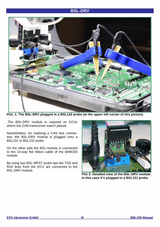
Pict. 1: The BSL-DRV plugged in a BSL132 probe (at the upper left corner of this picture).
.The BSL-DRV module is required on ECUswhere the CAN-transceiver wasn’t placed.
Nevertheless, for realizing a CAN bus connec-tion, the BSL-DRV module is plugged onto aBSL131 or BSL132 probe.
On the other side the BSL-module is connectedto the 14-way flat ribbon cable of the BDM100module.
By using two BSL-MPST probe tips the TXD andRxD lines from the ECU are connected to theBSL-DRV module.
Pict 2: Detailed view of the BSL-DRV module.In this case it’s plugged to a BSL131 probe.

EVC electronic GmbH -10- BSL100 Manual
BSL 100 Manual
BSL 100 Manual: April, 6th 20161st edition, 4th revision
Publisher: EVC electronic GmbH, 46539 Dinslaken
Author: Matthias Billian
Although we were afforded to describe all details with the highest possible precision, nevertheless wecan not guarantee an error free content of this manual.
EVC electronic GmbHAm Pfauenzehnt 11a
46539 Dinslakenwww.evc.de