manta ray user's guide series a.1.5 csa
TRANSCRIPT

www.greyline.com
USER'S GUIDE Installation & Operation
Instructions
Portable Area-Velocity Flow Meter
Model MantaRay
Manual Series A.1.5

Note: This page has been left blank intentionally.
Page 3
MantaRay Portable Area-Velocity Flow Meter
INDEX
CONNECTIONS ................................................................................................ 4
KEYPAD SYSTEM ............................................................................................ 5
BATTERY .......................................................................................................... 5
CALIBRATION MENU ..................................................................................... 6
ICONS ................................................................................................................. 6
MESSAGE ICON ............................................................................................... 8
STATUS ............................................................................................................. 8
PASSWORD ....................................................................................................... 9
UNITS/MODE .................................................................................................. 10
CALIBRATION................................................................................................ 11
RELAY PARAMETERS .................................................................................. 14
DATA LOGGING ............................................................................................ 15
SPECIAL FUNCTIONS ................................................................................... 17
INSTALLATION – SENSOR LOCATION ..................................................... 19
APPLICATIONS HOTLINE ............................................................................ 25
PRODUCT RETURN PROCEDURE ............................................................... 25
AREA-VELOCITY FLOW DATA SHEET ..................................................... 26
SPECIFICATIONS ........................................................................................... 30
IMPORTANT NOTE: This instrument is manufactured and calibrated to meet product specifications. Please read this manual carefully before installation and operation. Any unauthorized repairs or modifications may result in a suspension of the warranty.
Available in Adobe Acrobat pdf format
Page 4
MantaRay Portable Area-Velocity Flow Meter
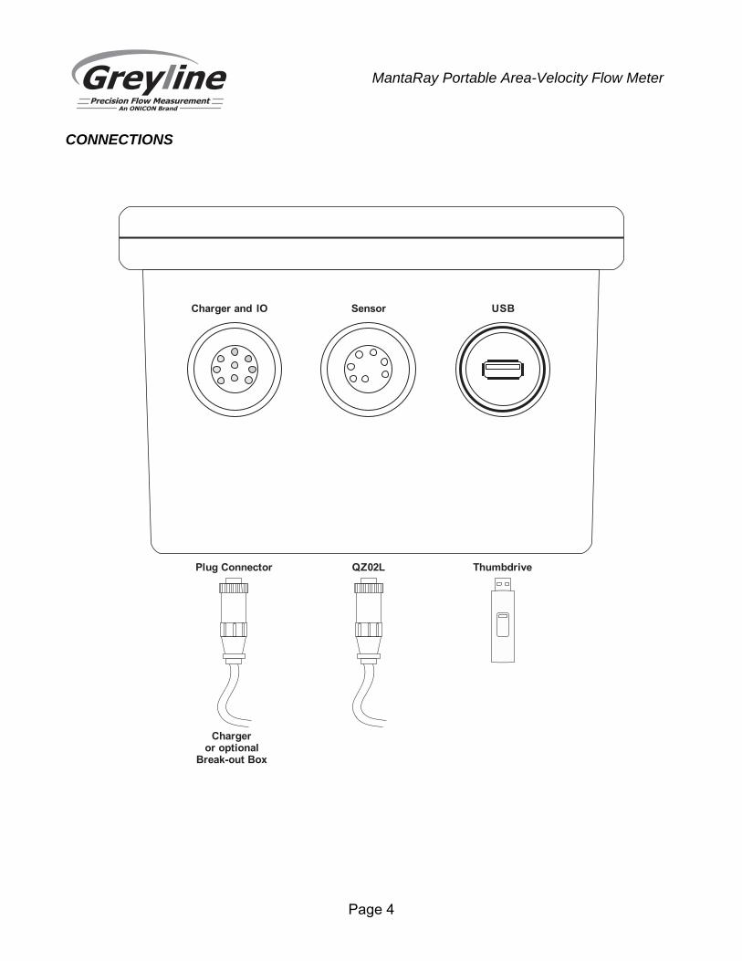
CONNECTIONS
Charger and IO Sensor USB
ThumbdriveQZ02LPlug Connector
Chargeror optional
Break-out Box
Page 5
MantaRay Portable Area-Velocity Flow Meter
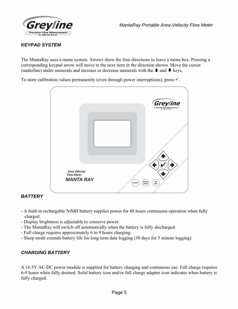
KEYPAD SYSTEM
The MantaRay uses a menu system. Arrows show the four directions to leave a menu box. Pressing a corresponding keypad arrow will move to the next item in the direction shown. Move the cursor (underline) under numerals and increase or decrease numerals with the and keys.
To store calibration values permanently (even through power interruptions), press .
BATTERY
- A built-in rechargable NiMH battery supplies power for 48 hours continuous operation when fully charged.
- Display brightness is adjustable to conserve power. - The MantaRay will switch off automatically when the battery is fully discharged. - Full charge requires approximately 6 to 9 hours charging. - Sleep mode extends battery life for long term data logging (30 days for 5 minute logging).
CHARGING BATTERY
A 16.5V AC-DC power module is supplied for battery charging and continuous use. Full charge requires 6-9 hours when fully drained. Solid battery icon and/or full charge adapter icon indicates when battery is fully charged.
Area VelocityFlow Meter
MANTA RAYSLEEP BACK
LIGHTONOFF
Page 6
MantaRay Portable Area-Velocity Flow Meter
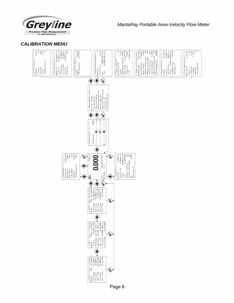
CALIBRATION MENU
--
Pa
ss
wo
rd
--
--
--
--
--
Pa
ss
wo
rd
00
00
--
Un
it
s/
Mo
de
--
--
--
--
Mo
de
Fl
ow
�
Li
ne
ar
in
Vo
lu
me
US
G
Ti
me
mi
n
Te
mp
er
at
ur
eC
US
G/
m
To
t 2
01
30
.8
US
G
Re
la
ys
1
2
0.000
--
Me
ss
ag
e-
--
--
--
--
--
Da
ta
Lo
gL
og
gi
ng
Ba
tt
er
y1
00
%
Ch
ar
ge
rO
ff
ud
2L
og
se
%
Se
ns
or
Go
od
Te
mp
er
at
ur
e2
4C
--
St
at
us
--
--
--
--
--
--
�L
ev
el
0.
00
ft
Ve
lo
ci
ty
0.
00
ft
/s
Fl
ow
0.
00
0 f
t/
s
To
t0
.0
00
US
G
Si
gn
al
Cu
to
ff
5%
Si
gn
al
St
re
ng
th
0%
EC
10
0%
Re
la
ys
1 2
--
Ca
li
br
at
io
n-
--
--
--
�2
0m
A F
lo
10
.0
00
ft
/s
³
4m
A F
lo
0.
00
0f
t/
s³
Mi
n L
ev
el
0.
00
0i
n
Lv
l O
ff
se
t0
.0
00
in
Mi
n V
el
0.
00
0f
t/
s
Da
mp
in
g1
0%
--
Re
la
y P
ar
am
et
er
s-
-
Re
la
y1
�
Fu
nc
ti
on
Fl
ow
/m
in
On
10
00
US
G
/m
in
Of
f0
.0
00
US
G
--
Sp
ec
ia
l F
un
ct
io
ns
-
La
ng
ua
ge
En
gl
is
h�
An
al
og
Ou
t4
-2
0m
A
Ba
ck
li
gh
tH
ig
h
Re
se
t T
ot
al
iz
er
NO
Ne
ga
ti
ve
To
ta
ls
NO
Fl
o D
ir
ec
ti
on
Of
f
Ca
l C
on
st
an
t1
.0
00
Re
st
or
e D
ef
au
lt
sN
O
Ne
w P
as
sw
or
d0
00
0
--
Da
ta
Lo
gg
in
g-
--
--
--
Lo
g S
it
e I
D0
�
Mo
de
Fl
ow
Se
t D
at
eM
ay
27
/2
01
3
Se
t T
im
e1
1:
27
:4
0
In
te
rv
al
10
se
c
Lo
gL
og
gi
ng
--
Co
nf
ig
ur
at
io
n-
--
--
�U
ti
li
ty
1.
25
.0
2
So
na
r1
.1
1
Do
pp
le
r1
.1
5
24
Lo
gg
er
1.
T 2R
el
ay
s
An
al
og
Ou
t1
--
--
--
-C
ha
nn
el
Se
tu
p-
�T
yp
eR
ou
nd
Ma
x H
ei
gh
t0
.7
5f
t
--
Me
nu
Se
le
ct
io
ns
--
--
Un
it
s /
Mo
de
�
Ca
li
br
at
io
n
Ch
an
ne
l S
et
up
Re
la
y P
ar
am
et
er
s
Da
ta
Lo
gg
in
g
Sp
ec
ia
l F
un
ct
io
ns
Si
mu
la
ti
on
Co
nf
ig
ur
at
io
n
--
24
hr
lo
g-
--
--
-F
lo
w
Da
te
Fe
b.
12
/2
0�
10
50
13
8 U
SG
To
ta
l
34
.8
2 U
SG
/m
Av
er
ag
e
52
.2
0 U
SG
/m
Ma
xi
mu
m
11
:0
8:
00
Ma
x T
im
e
0.
00
0 U
SG
/m
Mi
ni
mu
m
9:
15
:0
0M
in
Ti
me
--
24
hr
lo
g-
--
--
Le
ve
l
Da
te
Fe
b.
12
/2
0�
10
0.
00
0f
tA
ve
ra
ge
0.
00
0f
tM
ax
im
um
11
:0
8:
00
Ma
x T
im
e
0.
00
0f
tM
in
im
um
9:
15
:0
0M
in
Ti
me
--
24
hr
lo
g-
-V
el
oc
it
y
Da
te
Fe
b.
12
/2
0�
10
0.
00
0f
t/
sA
ve
ra
ge
0.
00
0f
t/
sM
ax
im
um
11
:0
8:
00
Ma
x T
im
e
0.
00
0f
t/
sM
in
im
um
9:
15
:0
0M
in
Ti
me
--
Si
mu
la
ti
on
--
--
--
--
�T
es
tA
ct
ua
l
Le
ve
l0
.0
0i
n
Ve
lo
ci
ty
10
ft
/s
Fl
ow
19
82
.8
8U
SG
/m
4-
20
mA
Fl
ow
20
.0
0
Re
la
ys
1 2
Page 7
MantaRay Portable Area-Velocity Flow Meter
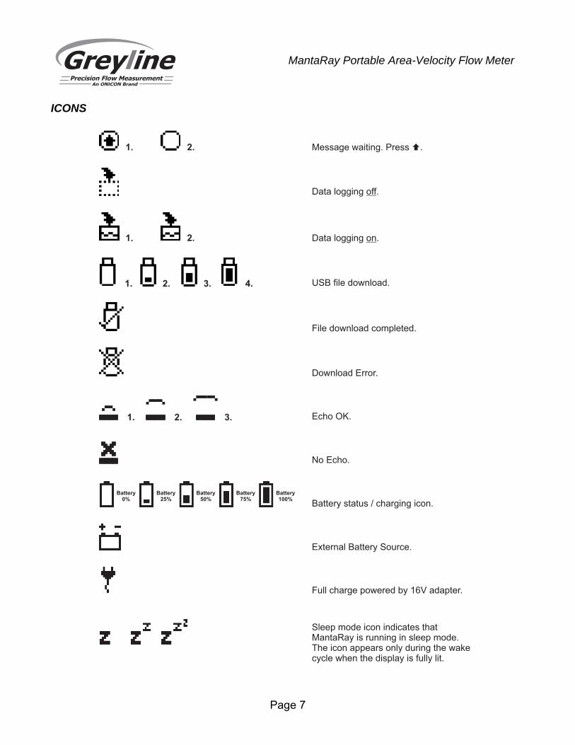
ICONS
1. 2. Message waiting. Press .�
Data logging .off
1. 2. Data logging .on
1. 2. 3. 4. USB file download.
File download completed.
Download Error.
Battery status / charging icon.
No Echo.
Echo OK.3.2.1.
External Battery Source.
Full charge powered by 16V adapter.
Battery0%
Battery25%
Battery50%
Battery75%
Battery100%
Sleep mode icon indicates thatManta ay is running in sleep mode.RThe icon appears only during the wakecycle when the display is fully lit.
Page 8
MantaRay Portable Area-Velocity Flow Meter
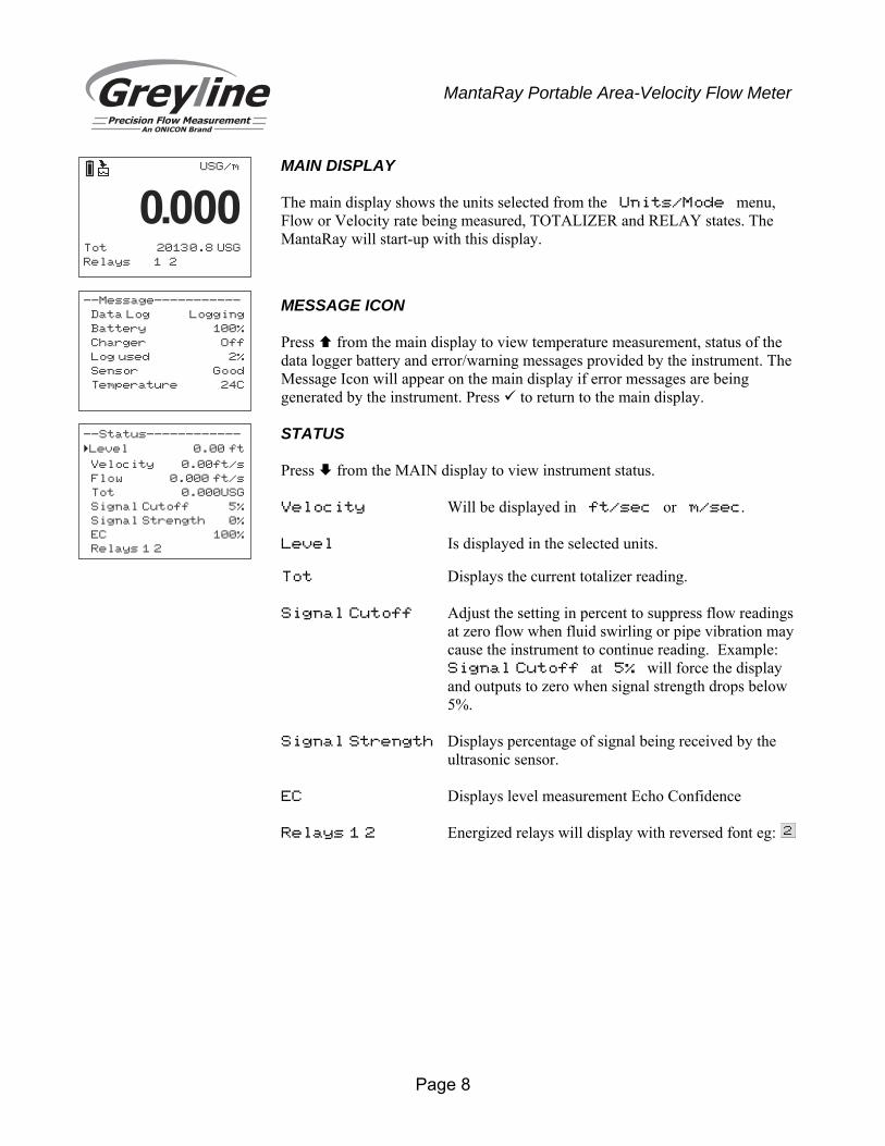
MAIN DISPLAY The main display shows the units selected from the Units/Mode menu, Flow or Velocity rate being measured, TOTALIZER and RELAY states. The MantaRay will start-up with this display.
MESSAGE ICON Press from the main display to view temperature measurement, status of the data logger battery and error/warning messages provided by the instrument. The Message Icon will appear on the main display if error messages are being generated by the instrument. Press to return to the main display.
STATUS Press from the MAIN display to view instrument status. Velocity Will be displayed in ft/sec or m/sec. Level Is displayed in the selected units. Tot Displays the current totalizer reading. Signal Cutoff Adjust the setting in percent to suppress flow readings
at zero flow when fluid swirling or pipe vibration may cause the instrument to continue reading. Example: Signal Cutoff at 5% will force the display and outputs to zero when signal strength drops below 5%.
Signal Strength Displays percentage of signal being received by the
ultrasonic sensor. EC Displays level measurement Echo Confidence Relays 1 2 Energized relays will display with reversed font eg:
USG/m
Tot 20130.8 USG
Relays 1 2
0.000
--Message-----------
Data Log Logging
Battery 100%
Charger Off
u d 2Log se %
Sensor Good
Temperature 24C
--Status------------
�Level 0.00 ft
Velocity 0.00ft/s
Flow 0.000 ft/s
Tot 0.000USG
Signal Cutoff 5%
Signal Strength 0%
EC 100%
Relays 1 2
Page 9
MantaRay Portable Area-Velocity Flow Meter
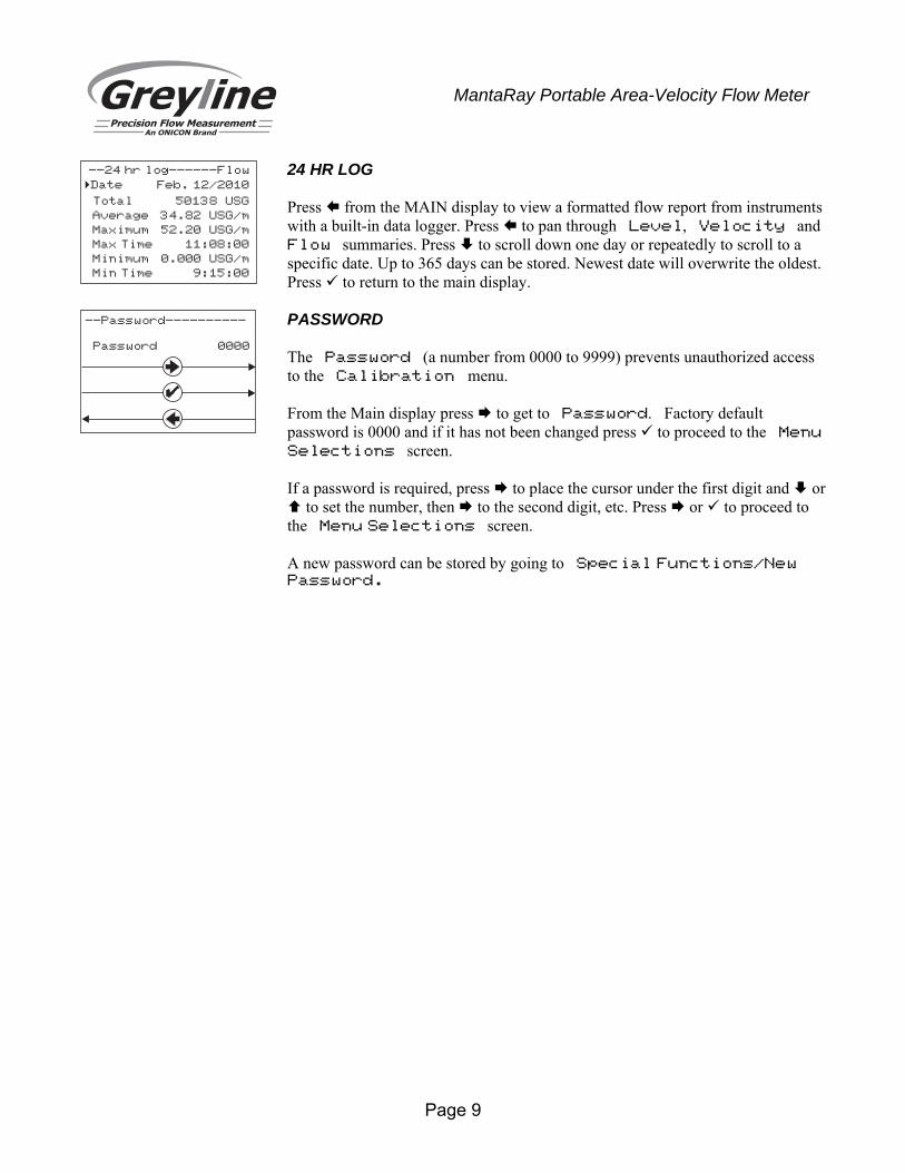
24 HR LOG Press from the MAIN display to view a formatted flow report from instruments with a built-in data logger. Press to pan through Level, Velocity and Flow summaries. Press to scroll down one day or repeatedly to scroll to a specific date. Up to 365 days can be stored. Newest date will overwrite the oldest. Press to return to the main display.
PASSWORD The Password (a number from 0000 to 9999) prevents unauthorized access to the Calibration menu. From the Main display press to get to Password. Factory default password is 0000 and if it has not been changed press to proceed to the Menu
Selections screen. If a password is required, press to place the cursor under the first digit and or to set the number, then to the second digit, etc. Press or to proceed to the Menu Selections screen. A new password can be stored by going to Special Functions/New Password.
--24 hr log------Flow
Date Feb. 12/2010
Total 50138 USG
Average 34.82 USG/m
Maximum 52.20 USG/m
Max Time 11:08:00
Minimum 0.000 USG/m
Min Time 9:15:00
�
--Password----------
Password 0000
Page 10
MantaRay Portable Area-Velocity Flow Meter
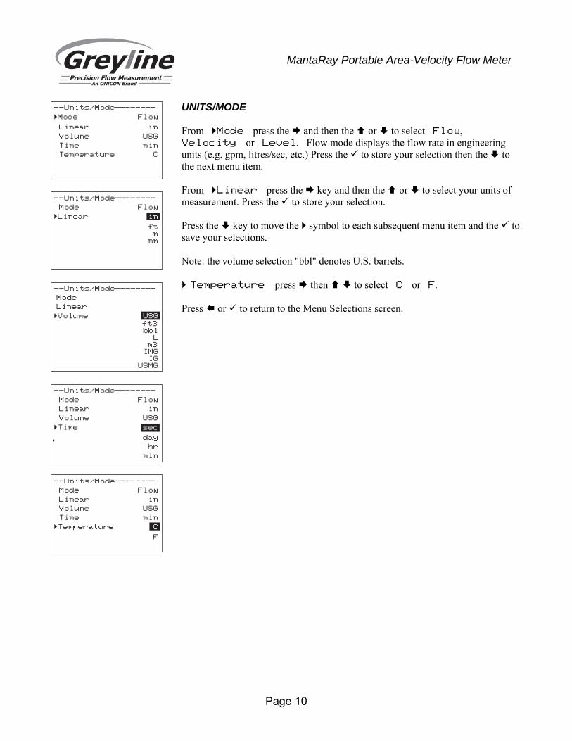
UNITS/MODE From Mode press the and then the or to select Flow, Velocity or Level. Flow mode displays the flow rate in engineering units (e.g. gpm, litres/sec, etc.) Press the to store your selection then the to the next menu item. From Linear press the key and then the or to select your units of measurement. Press the to store your selection. Press the key to move the symbol to each subsequent menu item and the to save your selections. Note: the volume selection "bbl" denotes U.S. barrels. Temperature press then to select C or F. Press or to return to the Menu Selections screen.
--Units/Mode--------
Mode Flow
Linear in
Volume USG
Time min
Temperature C
�
--Units/Mode--------
Mode Flow
Linear� in
ftm
mm
--Units/Mode--------
Mode
Linear
�Volume USG
ft3bbl
Lm3
IMGIG
USMG
--Units/Mode--------
Mode Flow
Linear in
Volume USG
Time� sec
day
hr
min
--Units/Mode--------
Mode Flow
Linear in
Volume USG
Time min
Temperature� C
F
Page 11
MantaRay Portable Area-Velocity Flow Meter
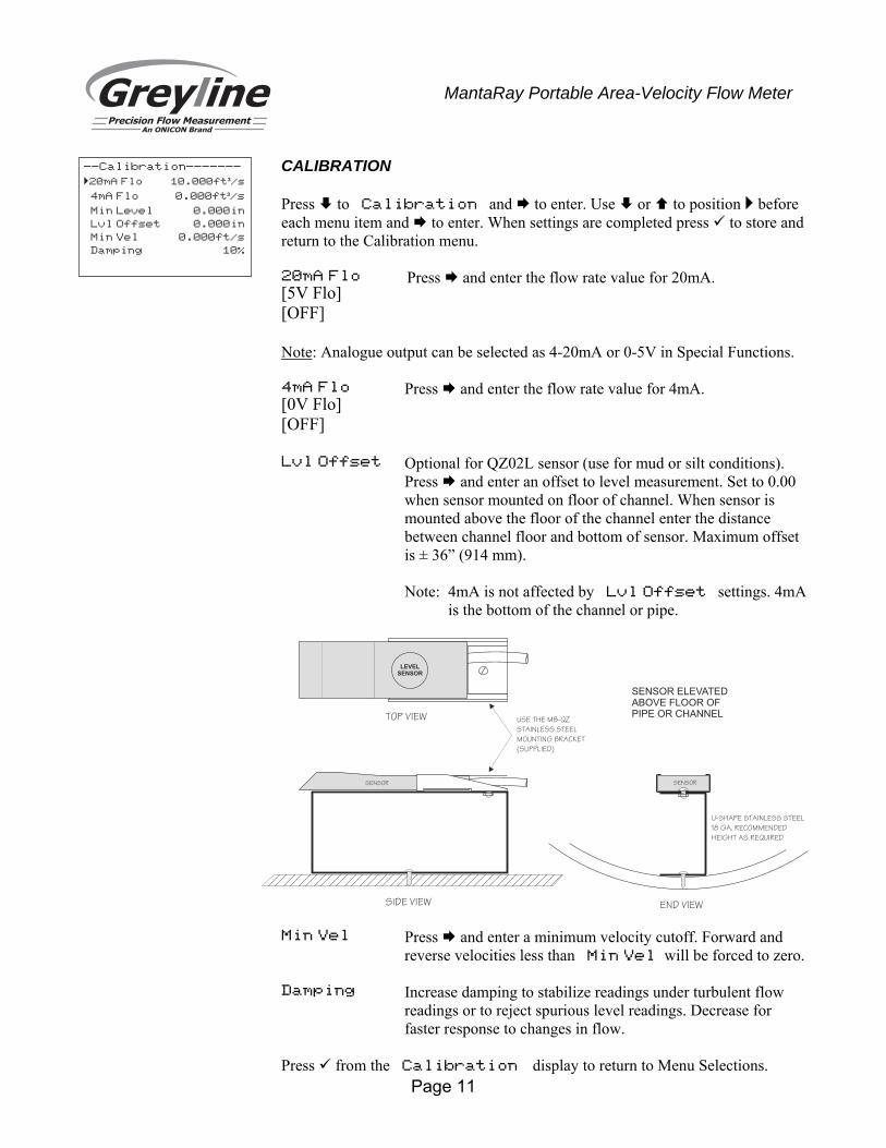
CALIBRATION Press to Calibration and to enter. Use or to position before each menu item and to enter. When settings are completed press to store and return to the Calibration menu. 20mA Flo [5V Flo] [OFF]
Press and enter the flow rate value for 20mA.
Note: Analogue output can be selected as 4-20mA or 0-5V in Special Functions. 4mA Flo [0V Flo] [OFF]
Press and enter the flow rate value for 4mA.
Lvl Offset Optional for QZ02L sensor (use for mud or silt conditions). Press and enter an offset to level measurement. Set to 0.00 when sensor mounted on floor of channel. When sensor is mounted above the floor of the channel enter the distance between channel floor and bottom of sensor. Maximum offset is ± 36” (914 mm).
Note: 4mA is not affected by Lvl Offset settings. 4mA is the bottom of the channel or pipe.
Min Vel Press and enter a minimum velocity cutoff. Forward and
reverse velocities less than Min Vel will be forced to zero.
Damping Increase damping to stabilize readings under turbulent flow readings or to reject spurious level readings. Decrease for faster response to changes in flow.
Press from the Calibration display to return to Menu Selections.
--Calibration-------
�20mA Flo 10.000ft /s³
4mA Flo 0.000ft /s³
Min Level 0.000in
Lvl Offset 0.000in
Min Vel 0.000ft/s
Damping 10%
SENSOR
END VIEWSIDE VIEW
TOP VIEW
SENSOR
U-SHAPE STAINLESS STEEL
18 GA. RECOMMENDED
HEIGHT AS REQUIRED
USE THE MB-QZ
STAINLESS STEEL
MOUNTING BRACKET
(SUPPLIED)
SENSOR ELEVATEDABOVE FLOOR OFPIPE OR CHANNEL
LEVELSENSOR
Page 12
MantaRay Portable Area-Velocity Flow Meter
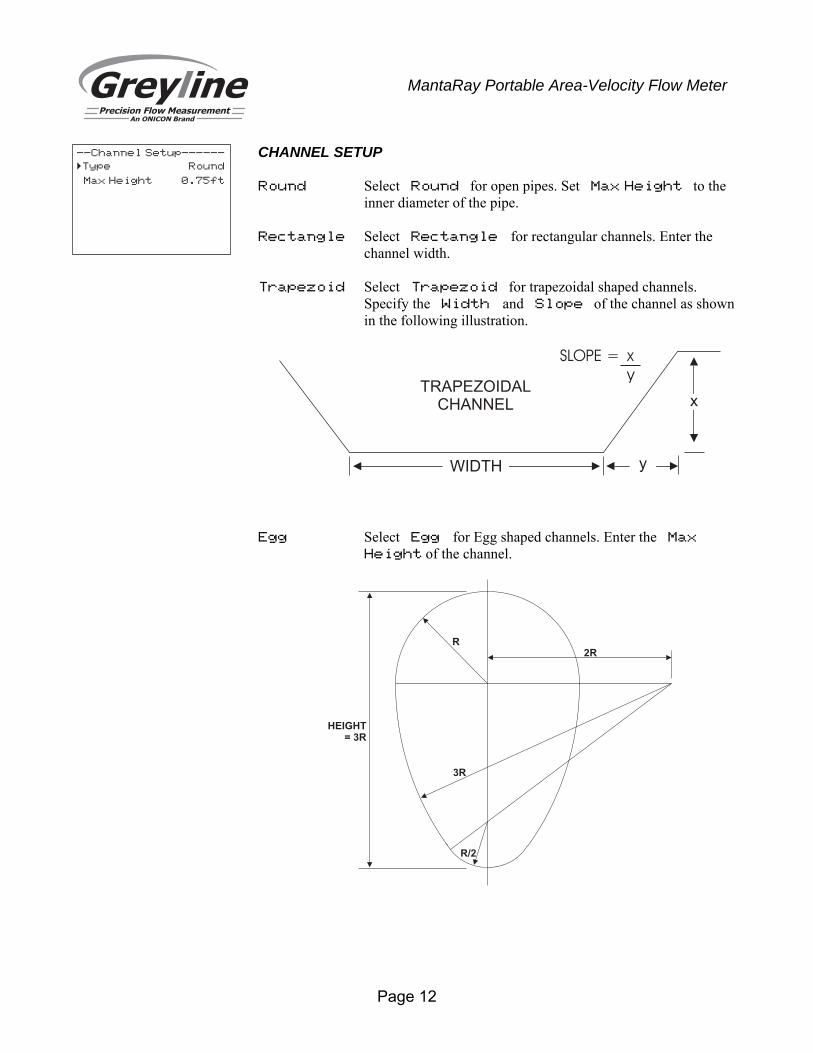
CHANNEL SETUP Round Select Round for open pipes. Set Max Height to the
inner diameter of the pipe. Rectangle Select Rectangle for rectangular channels. Enter the
channel width. Trapezoid Select Trapezoid for trapezoidal shaped channels.
Specify the Width and Slope of the channel as shown in the following illustration.
Egg Select Egg for Egg shaped channels. Enter the Max
Height of the channel.
--Channel Setup------
Type Round
Max Height 0.75ft
�
R
3R
R/2
2R
HEIGHT= 3R
TRAPEZOIDALCHANNEL
yWIDTH
x
SLOPE = x
y
Page 13
MantaRay Portable Area-Velocity Flow Meter
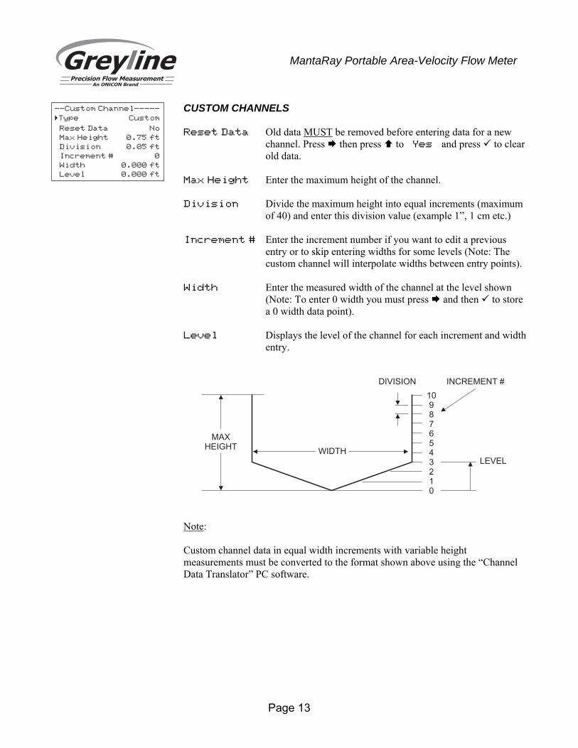
CUSTOM CHANNELS Reset Data Old data MUST be removed before entering data for a new
channel. Press then press to Yes and press to clear old data.
Max Height Enter the maximum height of the channel. Division Divide the maximum height into equal increments (maximum
of 40) and enter this division value (example 1”, 1 cm etc.) Increment # Enter the increment number if you want to edit a previous
entry or to skip entering widths for some levels (Note: The custom channel will interpolate widths between entry points).
Width Enter the measured width of the channel at the level shown
(Note: To enter 0 width you must press and then to store a 0 width data point).
Level Displays the level of the channel for each increment and width
entry.
Note: Custom channel data in equal width increments with variable height measurements must be converted to the format shown above using the “Channel Data Translator” PC software.
--Custom Channel-----
Type Custom
Reset Data No
Max Height 0.75 ft
Division 0.05 ft
Increment # 0
Width 0.000 ft
Level 0.000 ft
�
MAXHEIGHT
109876543210
WIDTH
INCREMENT #DIVISION
LEVEL
Page 14
MantaRay Portable Area-Velocity Flow Meter
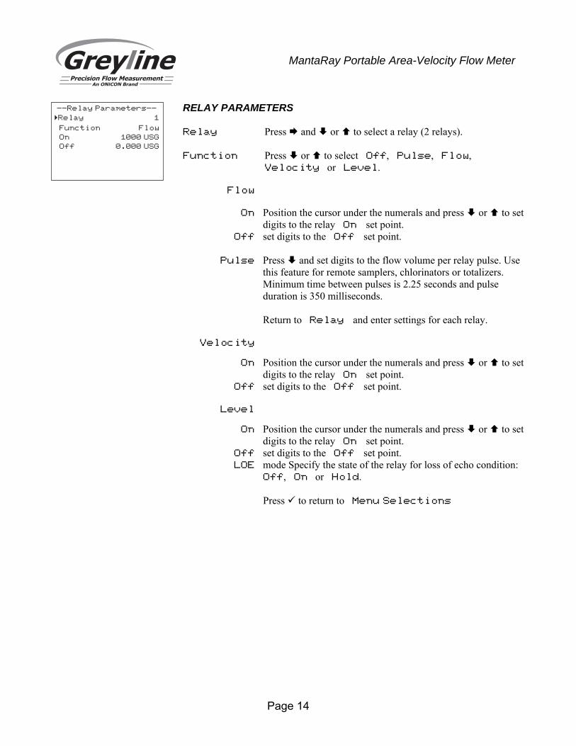
RELAY PARAMETERS Relay Press and or to select a relay (2 relays). Function Press or to select Off, Pulse, Flow,
Velocity or Level. Flow On Position the cursor under the numerals and press or to set
digits to the relay On set point. Off set digits to the Off set point. Pulse Press and set digits to the flow volume per relay pulse. Use
this feature for remote samplers, chlorinators or totalizers. Minimum time between pulses is 2.25 seconds and pulse duration is 350 milliseconds.
Return to Relay and enter settings for each relay. Velocity On Position the cursor under the numerals and press or to set
digits to the relay On set point. Off set digits to the Off set point. Level On Position the cursor under the numerals and press or to set
digits to the relay On set point. Off set digits to the Off set point. LOE mode Specify the state of the relay for loss of echo condition:
Off, On or Hold.
Press to return to Menu Selections
--Relay Parameters--
Relay 1
Function Flow
On 1000 USG
Off 0.000 USG
�
Page 15
MantaRay Portable Area-Velocity Flow Meter
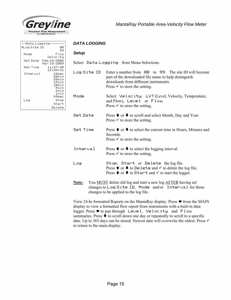
DATA LOGGING Setup Select Data Logging from Menu Selections. Log Site ID Enter a number from 00 to 99. The site ID will become
part of the downloaded file name to help distinguish downloads from different instruments.
Press to store the setting. Mode Select Velocity, LVT (Level, Velocity, Temperature,
and Flow), Level or Flow. Press to store the setting. Set Date Press or to scroll and select Month, Day and Year. Press to store the setting. Set Time Press or to select the current time in Hours, Minutes and
Seconds. Press to store the setting. Interval Press or to select the logging interval. Press to store the setting. Log Stop, Start or Delete the log file. Press or to Delete and to delete the log file. Press or to Start and to start the logger. Note: You MUST delete old log and start a new log AFTER having set
changes to Log Site ID, Mode and/or Interval for those changes to be applied to the log file.
View 24-hr formatted Reports on the MantaRay display. Press from the MAIN display to view a formatted flow report from instruments with a built-in data logger. Press to pan through Level, Velocity and Flow summaries. Press to scroll down one day or repeatedly to scroll to a specific date. Up to 365 days can be stored. Newest date will overwrite the oldest. Press to return to the main display.
--Data Logging-------
Log Site ID 00
99
Mode FlowVelocity
Set Date Feb 18/2008Mar 19/2009
Set Time 11:27:4012:28:41
Interval 10sec60min30min15min10min
5min2min1min
30sec
Log Stop
Start
Delete
�
Page 16
MantaRay Portable Area-Velocity Flow Meter
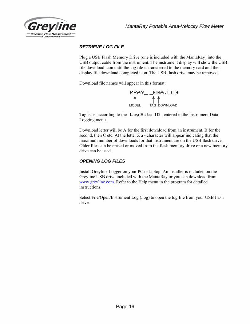
RETRIEVE LOG FILE Plug a USB Flash Memory Drive (one is included with the MantaRay) into the USB output cable from the instrument. The instrument display will show the USB file download icon until the log file is transferred to the memory card and then display file download completed icon. The USB flash drive may be removed. Download file names will appear in this format:
Tag is set according to the Log Site ID entered in the instrument Data Logging menu. Download letter will be A for the first download from an instrument. B for the second, then C etc. At the letter Z a - character will appear indicating that the maximum number of downloads for that instrument are on the USB flash drive. Older files can be erased or moved from the flash memory drive or a new memory drive can be used.
OPENING LOG FILES Install Greyline Logger on your PC or laptop. An installer is included on the Greyline USB drive included with the MantaRay or you can download from www.greyline.com. Refer to the Help menu in the program for detailed instructions. Select File/Open/Instrument Log (.log) to open the log file from your USB flash drive.
MRAY_ _00A.LOG
MODEL TAG DOWNLOAD
Page 17
MantaRay Portable Area-Velocity Flow Meter
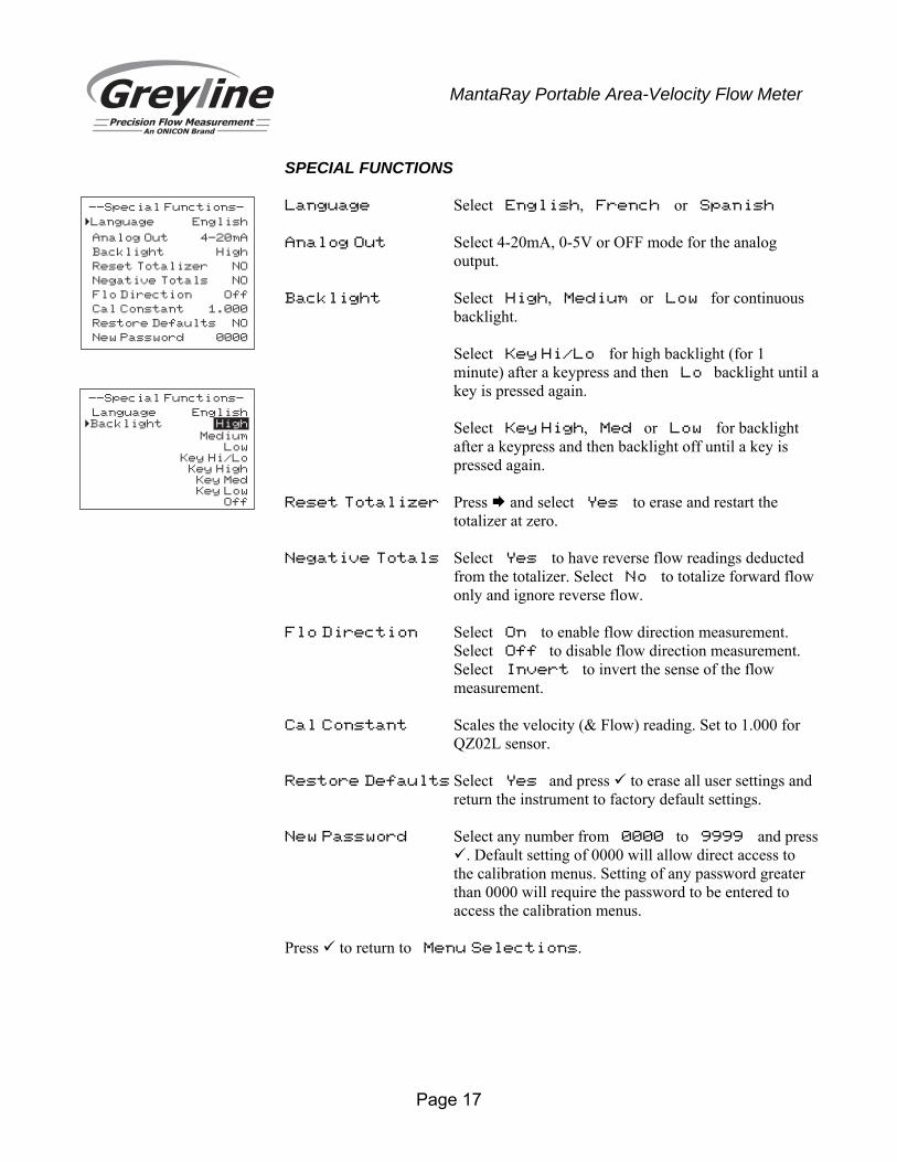
SPECIAL FUNCTIONS Language Select English, French or Spanish Analog Out Select 4-20mA, 0-5V or OFF mode for the analog
output. Backlight Select High, Medium or Low for continuous
backlight. Select Key Hi/Lo for high backlight (for 1 minute) after a keypress and then Lo backlight until a key is pressed again. Select Key High, Med or Low for backlight after a keypress and then backlight off until a key is pressed again.
Reset Totalizer Press and select Yes to erase and restart the
totalizer at zero. Negative Totals Select Yes to have reverse flow readings deducted
from the totalizer. Select No to totalize forward flow only and ignore reverse flow.
Flo Direction Select On to enable flow direction measurement.
Select Off to disable flow direction measurement. Select Invert to invert the sense of the flow measurement.
Cal Constant Scales the velocity (& Flow) reading. Set to 1.000 for
QZ02L sensor. Restore Defaults Select Yes and press to erase all user settings and
return the instrument to factory default settings. New Password Select any number from 0000 to 9999 and press
. Default setting of 0000 will allow direct access to the calibration menus. Setting of any password greater than 0000 will require the password to be entered to access the calibration menus.
Press to return to Menu Selections.
--Special Functions-
Language English
Analog Out 4-20mA
Backlight High
Reset Totalizer NO
Negative Totals NO
Flo Direction Off
Cal Constant 1.000
Restore Defaults NO
New Password 0000
�
--Special Functions-
Language English�Backlight High
MediumLow
Key Hi/LoKey High
Key MedKey Low
Off
Page 18
MantaRay Portable Area-Velocity Flow Meter
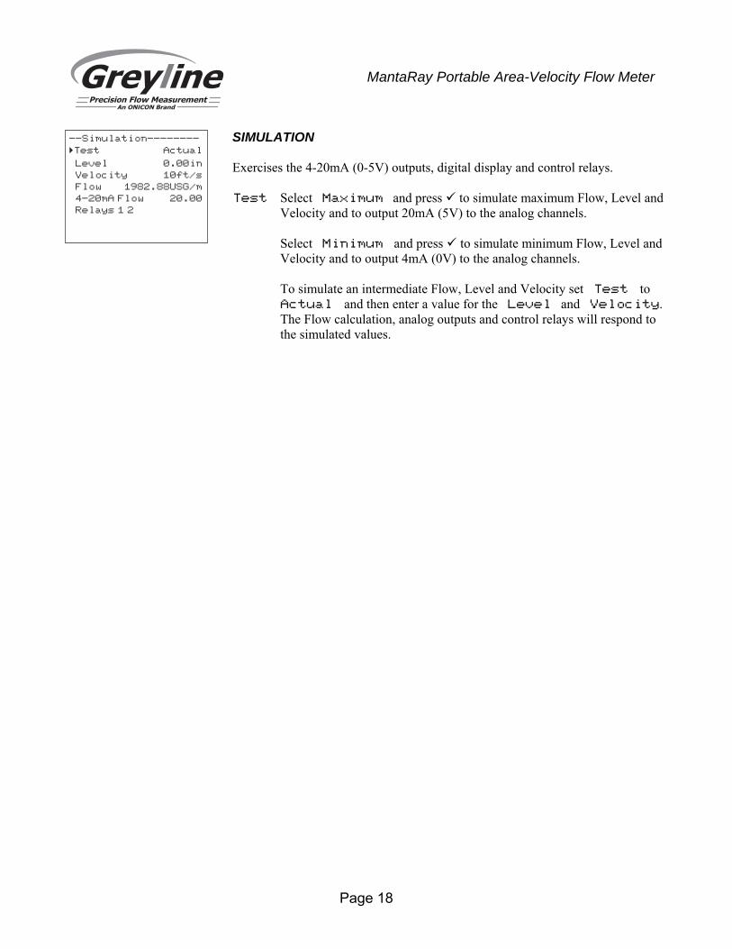
SIMULATION Exercises the 4-20mA (0-5V) outputs, digital display and control relays. Test Select Maximum and press to simulate maximum Flow, Level and
Velocity and to output 20mA (5V) to the analog channels. Select Minimum and press to simulate minimum Flow, Level and
Velocity and to output 4mA (0V) to the analog channels. To simulate an intermediate Flow, Level and Velocity set Test to
Actual and then enter a value for the Level and Velocity. The Flow calculation, analog outputs and control relays will respond to the simulated values.
--Simulation--------
�Test Actual
Level 0.00in
Velocity 10ft/s
Flow 1982.88USG/m
4-20mA Flow 20.00
Relays 1 2
Page 19
MantaRay Portable Area-Velocity Flow Meter
INSTALLATION – SENSOR LOCATION
For the most accurate flow measurement possible, careful consideration should be made to the placement of the sensor in relation to flow disturbances. In general, the best accuracy will occur where flow is evenly distributed across the channel/pipe and free of turbulence.
Specific installation considerations are listed and discussed in more detail below.
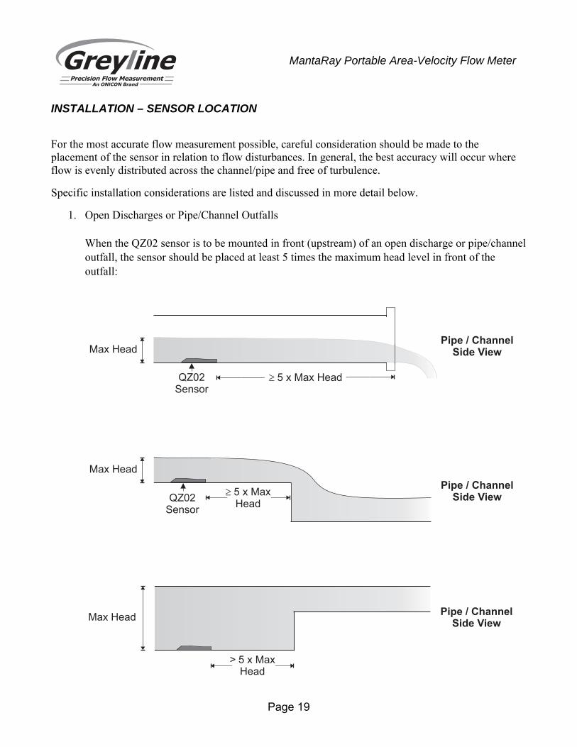
1. Open Discharges or Pipe/Channel Outfalls When the QZ02 sensor is to be mounted in front (upstream) of an open discharge or pipe/channel outfall, the sensor should be placed at least 5 times the maximum head level in front of the outfall:
Pipe / ChannelSide View
Pipe / ChannelSide ViewQZ02
Sensor
Max Head
� 5 x MaxHead
QZ02Sensor
Max Head
� 5 x Max Head
Max Head
> 5 x MaxHead
Pipe / ChannelSide View

Page 20
MantaRay Portable Area-Velocity Flow Meter
2. Hydraulic Dams When the QZ02 sensor is to be mounted in front (upstream) of a hydraulic dam, or a Greyline VD pipe dam, the sensor should be placed at least 20 inches in front of the dam. Important note: Best results when using a dam occur when the pipe/channel grade is less than 1%.
3. Pipe Grade The pipe/channel in which the QZ02 sensor is mounted should not have a grade exceeding 3%. If a pipe/channel dam is used, slope should be less than 1% for best results.
QZ02Sensor
Hydraulic Damor
VD Pipe Dam
Max Head
Pipe / ChannelSide View
� 5 x Max Head
Pipe / ChannelSide View
QZ02Sensor
Grade 3%�
Page 21
MantaRay Portable Area-Velocity Flow Meter
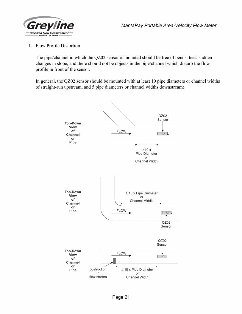
1. Flow Profile Distortion The pipe/channel in which the QZ02 sensor is mounted should be free of bends, tees, sudden changes in slope, and there should not be objects in the pipe/channel which disturb the flow profile in front of the sensor. In general, the QZ02 sensor should be mounted with at least 10 pipe diameters or channel widths of straight-run upstream, and 5 pipe diameters or channel widths downstream:
Top-DownView
ofChannel
orPipe
QZ02Sensor
� 10 xPipe Diameter
orChannel Width
FLOW
Top-DownView
ofChannel
orPipe
FLOW
QZ02Sensor
� 10 x Pipe Diameteror
Channel Width
obstructionin
flow stream
Top-DownView
ofChannel
orPipe FLOW
QZ02Sensor
� 10 x Pipe Diameteror
Channel Middle
Page 22
MantaRay Portable Area-Velocity Flow Meter
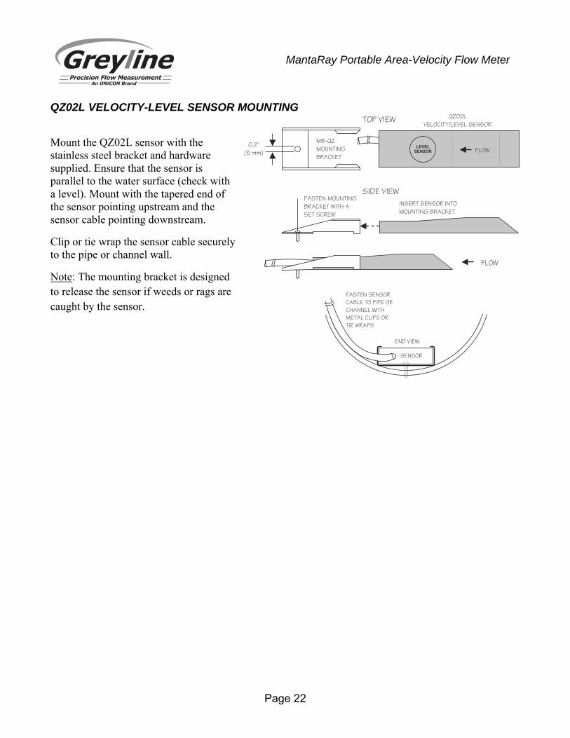
QZ02L VELOCITY-LEVEL SENSOR MOUNTING
Mount the QZ02L sensor with the stainless steel bracket and hardware supplied. Ensure that the sensor is parallel to the water surface (check with a level). Mount with the tapered end of the sensor pointing upstream and the sensor cable pointing downstream.
Clip or tie wrap the sensor cable securely to the pipe or channel wall.
Note: The mounting bracket is designed to release the sensor if weeds or rags are caught by the sensor.
FASTEN SENSOR
CABLE TO PIPE OR
CHANNEL WITH
METAL CLIPS OR
TIE WRAPS
SENSOR
END VIEW
MB-QZ
MOUNTING
BRACKET
0.2"
(5 mm)
TOP VIEW
FLOW
SIDE VIEWFASTEN MOUNTING
BRACKET WITH A
SET SCREW
INSERT SENSOR INTO
MOUNTING BRACKET
QZ02L
VELOCITY/LEVEL SENSOR
FLOWLEVEL
SENSOR
Page 23
MantaRay Portable Area-Velocity Flow Meter
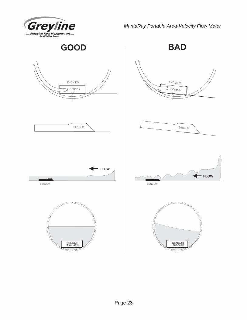
GOOD BAD
SENSOR
END VIEW
SENSOREND VIEW
SENSOREND VIEW
SENSOR
END VIEW
SENSOR SENSOR
SENSOR
FLOW
SENSOR
FLOW
Page 24
MantaRay Portable Area-Velocity Flow Meter
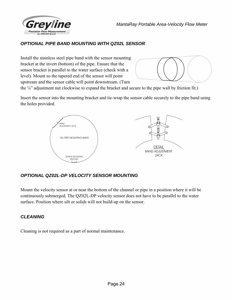
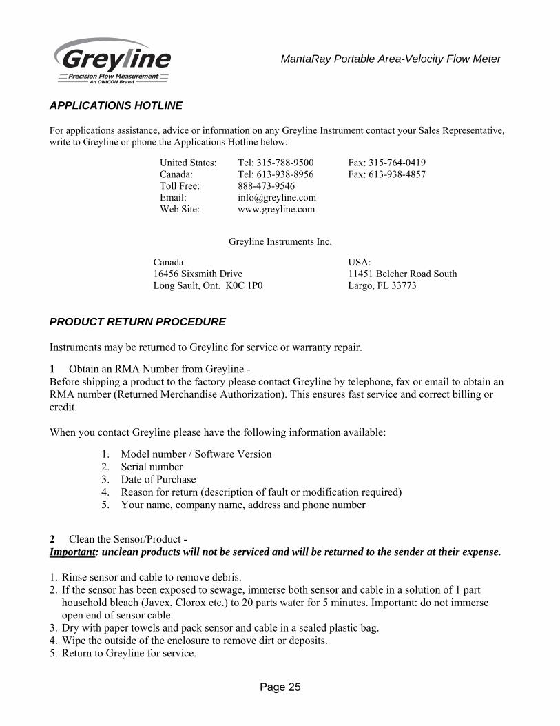
OPTIONAL PIPE BAND MOUNTING WITH QZ02L SENSOR
Install the stainless steel pipe band with the sensor mounting bracket at the invert (bottom) of the pipe. Ensure that the sensor bracket is parallel to the water surface (check with a level). Mount so the tapered end of the sensor will point upstream and the sensor cable will point downstream. (Turn the ¼” adjustment nut clockwise to expand the bracket and secure to the pipe wall by friction fit.)
Insert the sensor into the mounting bracket and tie-wrap the sensor cable securely to the pipe band using the holes provided.
OPTIONAL QZ02L-DP VELOCITY SENSOR MOUNTING
Mount the velocity sensor at or near the bottom of the channel or pipe in a position where it will be continuously submerged. The QZ02L-DP velocity sensor does not have to be parallel to the water surface. Position where silt or solids will not build-up on the sensor.
CLEANING
Cleaning is not required as a part of normal maintenance.
DETAILBAND ADJUSTMENT
JACK
VSJ PIPE MOUNTING BAND
BAND
ADJUSTMENT JACK
SENSOR MOUNTING
BRACKET
Page 25
MantaRay Portable Area-Velocity Flow Meter
APPLICATIONS HOTLINE For applications assistance, advice or information on any Greyline Instrument contact your Sales Representative, write to Greyline or phone the Applications Hotline below:
United States: Tel: 315-788-9500 Fax: 315-764-0419 Canada: Tel: 613-938-8956 Fax: 613-938-4857 Toll Free: 888-473-9546 Email: [email protected] Web Site: www.greyline.com
Greyline Instruments Inc.
Canada USA: 16456 Sixsmith Drive 11451 Belcher Road South Long Sault, Ont. K0C 1P0 Largo, FL 33773 PRODUCT RETURN PROCEDURE Instruments may be returned to Greyline for service or warranty repair.
1 Obtain an RMA Number from Greyline - Before shipping a product to the factory please contact Greyline by telephone, fax or email to obtain an RMA number (Returned Merchandise Authorization). This ensures fast service and correct billing or credit. When you contact Greyline please have the following information available:
1. Model number / Software Version 2. Serial number 3. Date of Purchase 4. Reason for return (description of fault or modification required) 5. Your name, company name, address and phone number
2 Clean the Sensor/Product - Important: unclean products will not be serviced and will be returned to the sender at their expense. 1. Rinse sensor and cable to remove debris. 2. If the sensor has been exposed to sewage, immerse both sensor and cable in a solution of 1 part
household bleach (Javex, Clorox etc.) to 20 parts water for 5 minutes. Important: do not immerse open end of sensor cable.
3. Dry with paper towels and pack sensor and cable in a sealed plastic bag. 4. Wipe the outside of the enclosure to remove dirt or deposits. 5. Return to Greyline for service.
Page 26
MantaRay Portable Area-Velocity Flow Meter
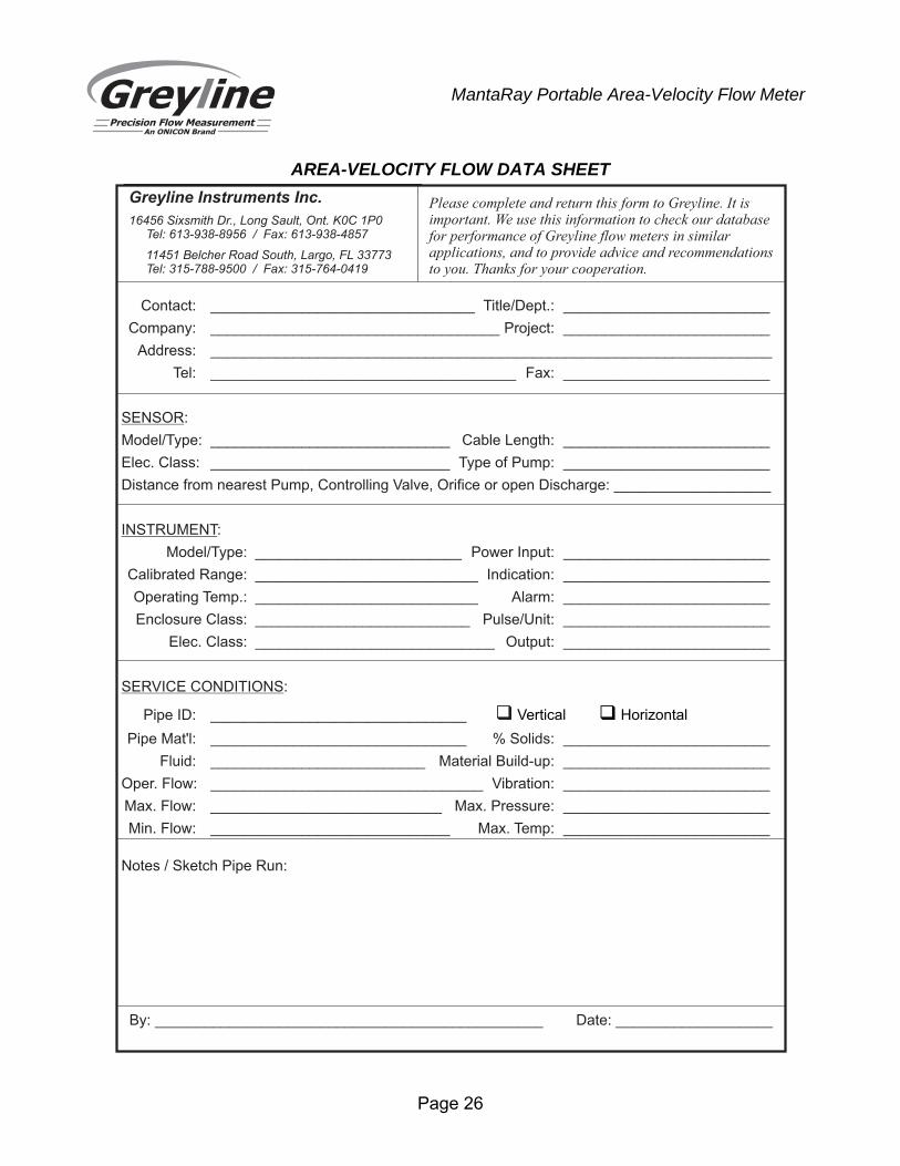
AREA-VELOCITY FLOW DATA SHEET
Greyline Instruments Inc.
16456 Sixsmith Dr., Long Sault, Ont. K0C 1P0Tel: 613-938-8956 / Fax: 613-938-4857
11451 Belcher Road South, Largo, FL 33773Tel: 315-788-9500 / Fax: 315-764-0419
Please complete and return this form to Greyline. It isimportant. We use this information to check our databasefor performance of Greyline flow meters in similarapplications, and to provide advice and recommendationsto you. Thanks for your cooperation.
Contact: ________________________________ Title/Dept.: _________________________
Company: ___________________________________ Project: _________________________
Address: ____________________________________________________________________
Tel: _____________________________________ Fax: _________________________
SENSOR:
Model/Type: _____________________________ Cable Length: _________________________
Elec. Class: _____________________________ Type of Pump: _________________________
Distance from nearest Pump, Controlling Valve, Orifice or open Discharge: ___________________
INSTRUMENT:
Model/Type: _________________________ Power Input: _________________________
Calibrated Range: ___________________________ Indication: _________________________
Operating Temp.: ___________________________ Alarm: _________________________
Enclosure Class: __________________________ Pulse/Unit: _________________________
Elec. Class: _____________________________ Output: _________________________
SERVICE CONDITIONS:
Pipe ID: _______________________________ � Vertical Horizontal�
Pipe Mat'l: _______________________________ % Solids: _________________________
Fluid: __________________________ Material Build-up: _________________________
Oper. Flow: _________________________________ Vibration: _________________________
Max. Flow: ____________________________ Max. Pressure: _________________________
Min. Flow: _____________________________ Max. Temp: _________________________
Notes / Sketch Pipe Run:
By: _______________________________________________ Date: ___________________
Page 27
MantaRay Portable Area-Velocity Flow Meter
LIMITED WARRANTY _____________________________________
Greyline Instruments warrants, to the original purchaser, its products to be free from defects in material and workmanship for a period of one year from date of invoice. Greyline will replace or repair, free of charge, any Greyline product if it has been proven to be defective within the warranty period. This warranty does not cover any expenses incurred in the removal and re-installation of the product.
If a product manufactured by Greyline should prove defective within the first year, return it freight prepaid to Greyline Instruments along with a copy of your invoice.
This warranty does not cover damages due to improper installation or handling, acts of nature, or unauthorized service. Modifications to or tampering with any part shall void this warranty. This warranty does not cover any equipment used in connection with the product or consequential damages due to a defect in the product.
All implied warranties are limited to the duration of this warranty. This is the complete warranty by Greyline and no other warranty is valid against Greyline. Some states do not allow limitations on how long an implied warranty lasts or limitation of incidental or consequential damages, so the above limitations or exclusions may not apply to you.
This warranty gives you specific legal rights, and you may also have other rights which vary from state to state.
Greyline Instruments Inc.
Page 28
MantaRay Portable Area-Velocity Flow Meter
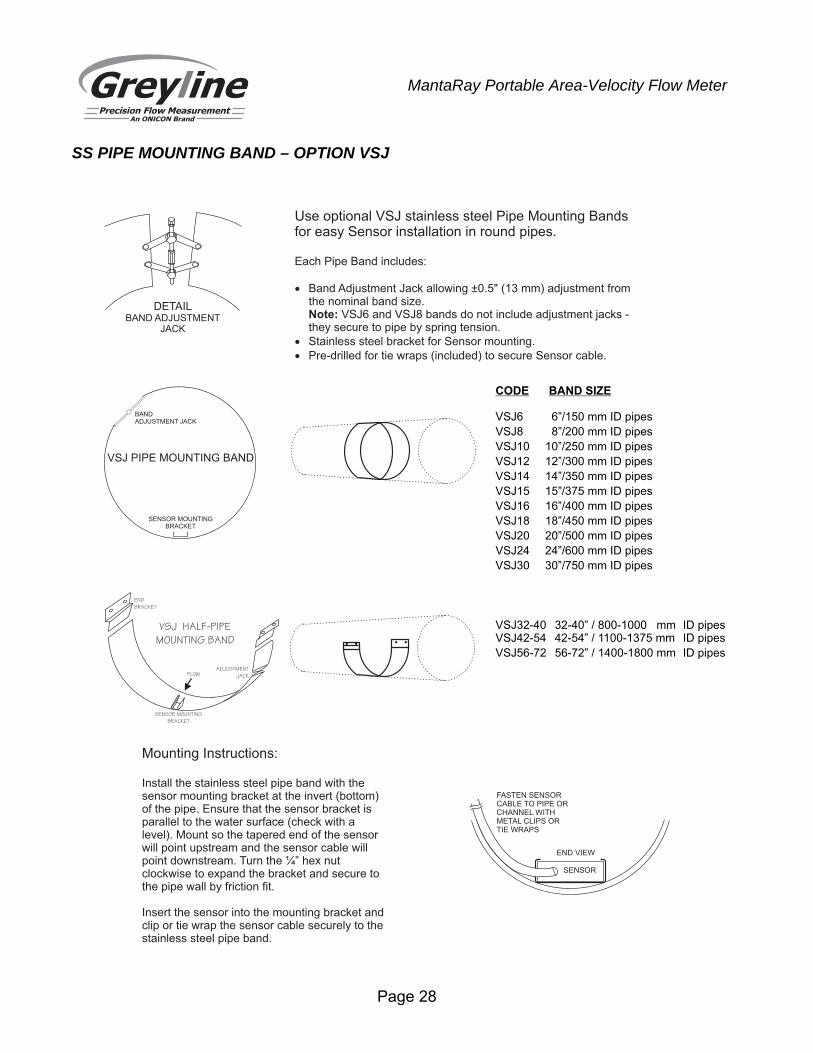
SS PIPE MOUNTING BAND – OPTION VSJ
CODE BAND SIZE
VSJ6 6”/150 mm ID pipes
VSJ8 8”/200 mm ID pipes
VSJ10 10”/250 mm ID pipes
VSJ12 12”/300 mm ID pipes
VSJ14 14”/350 mm ID pipes
VSJ15 15”/375 mm ID pipes
VSJ16 16”/400 mm ID pipes
VSJ18 18”/450 mm ID pipes
VSJ20 20”/500 mm ID pipes
VSJ24 24”/600 mm ID pipes
VSJ30 30”/750 mm ID pipes
VSJ32-40 32-40” / 800-1000 mm ID pipesVSJ42-54 42-54” / 1100-1375 mm ID pipes
VSJ56-72 56-72” / 1400-1800 mm ID pipes
DETAILBAND ADJUSTMENT
JACK
VSJ PIPE MOUNTING BAND
BANDADJUSTMENT JACK
SENSOR MOUNTINGBRACKET
Mounting Instructions:
Install the stainless steel pipe band with thesensor mounting bracket at the invert (bottom)of the pipe. Ensure that the sensor bracket isparallel to the water surface (check with alevel). Mount so the tapered end of the sensorwill point upstream and the sensor cable willpoint downstream. Turn the ¼” hex nutclockwise to expand the bracket and secure tothe pipe wall by friction fit.
Insert the sensor into the mounting bracket andclip or tie wrap the sensor cable securely to thestainless steel pipe band.
FASTEN SENSORCABLE TO PIPE ORCHANNEL WITHMETAL CLIPS ORTIE WRAPS
SENSOR
END VIEW
VSJ HALF-PIPE
MOUNTING BAND
ADJUSTMENT
JACK
SENSOR MOUNTING
BRACKET
END
BRACKET
FLOW
Use optional VSJ stainless steel Pipe Mounting Bandsfor easy Sensor installation in round pipes.
Each Pipe Band includes:
� Band Adjustment Jack allowing ±0.5" (13 mm) adjustment fromthe nominal band size.
VSJ6 and VSJ8 bands do not include adjustment jacks -Note:they secure to pipe by spring tension.
� Stainless steel bracket for Sensor mounting.
� Pre-drilled for tie wraps (included) to secure Sensor cable.
Page 29
MantaRay Portable Area-Velocity Flow Meter
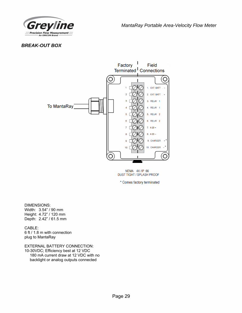
BREAK-OUT BOX
DIMENSIONS: Width: 3.54” / 90 mm Height: 4.72” / 120 mm Depth: 2.42” / 61.5 mm CABLE: 6 ft / 1.8 m with connection plug to MantaRay EXTERNAL BATTERY CONNECTION: 10-30VDC; Efficiency best at 12 VDC 180 mA current draw at 12 VDC with no
backlight or analog outputs connected
Page 30
MantaRay Portable Area-Velocity Flow Meter
SPECIFICATIONS Channel Types: Round pipe, Rectangular, trapezoid, egg or custom shapes Electronics Enclosure: Watertight, airtight, dust proof (IP 67) polycarbonate Operating Temp. (Electronics): -5° to 140°F (-20° to 60°C) Accuracy: Level: ± 0.25% of Range Velocity: ± 2% of Reading. Requires solids or bubbles minimum size of
100 microns, minimum concentration 75 ppm. Repeatability: 0.1% of Full Scale, Linearity: 0.1% of Full Scale Display: White, backlit matrix - displays flow rate, totalizer, relay states, operating
mode and calibration menu Programming: built-in 5-key calibrator with English, French or Spanish language
selection Battery: internal rechargeable NiMH, 12VDC, 10,000 mAh Power Brick: 6.0A (99W Max), 100-240VAC 50/60Hz input, UL and CE listed Outputs/Communications: 4-20mA, 500 ohm or 0-5VDC (100 mA) by menu selection 2 solid-state Relays, 32V AC/DC max., rated 400mA; programmable for
flow proportional pulse (sampler/totalizer), flow and/or level alarm Breakout Box: Connections for charger input, external battery input, 2 relays, 4-20mA
(0-5V) Electrical Surge Protection: Sensor, 4-20mA outputs and AC power input Data Logger: Programmable 2-million point data capacity, time and date stamped
plus formatted flow reports including Total, Average, Minimum, Maximum and times of occurrence. Includes USB output to Flash Drives
Logger Intervals: programmable 10, 30 sec, 1, 2, 5, 10, 15, 30, 60 min Software: Greyline Logger for Windows. Graph and data table presentation,
level/velocity to flow conversion, exports data to Excel™, exports graphs
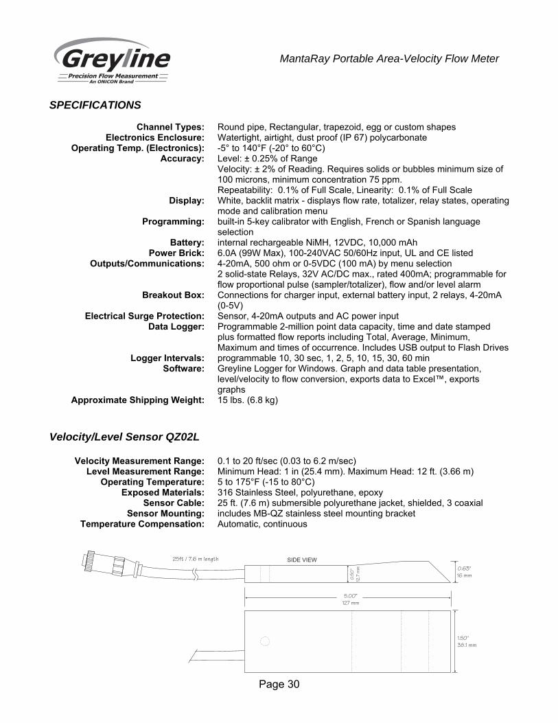
Approximate Shipping Weight: 15 lbs. (6.8 kg) Velocity/Level Sensor QZ02L Velocity Measurement Range: 0.1 to 20 ft/sec (0.03 to 6.2 m/sec) Level Measurement Range: Minimum Head: 1 in (25.4 mm). Maximum Head: 12 ft. (3.66 m) Operating Temperature: 5 to 175°F (-15 to 80°C) Exposed Materials: 316 Stainless Steel, polyurethane, epoxy Sensor Cable: 25 ft. (7.6 m) submersible polyurethane jacket, shielded, 3 coaxial Sensor Mounting: includes MB-QZ stainless steel mounting bracket Temperature Compensation: Automatic, continuous
5.00”
127 mm
1.50"
38.1 mm
0.63"
16 mm
SIDE VIEW
0.5
0"
12.7
mm
25ft / 7.6 m length
