manipulator systems: a means for doing underwater work
TRANSCRIPT

ROBERT A. JONES
MAATIPVLATOR SYJTElMS A MEANS FOR DONG UADER WATER WORK
THE AUTHOR is a naval architect in the Weapons and Deck Systems and Equipment Branch of the Naval Ship Engineering Center, Washington, D. C. He holds a Bachelor of Science degree in Mechanical Engineering from the University of Illinois. Since joining NAVSEC in 1965 he has taken part in the Hull Systems and Weapons Support Division Junior Engineer Training Program. Responsibilities of his present position kclude design and system engineering for submersible vehicle mechan- ical systems, equipment jettisoning systems, underwater work tools, and submersible vehicle certification. He is a registered engineer in training in the state of Illinois.
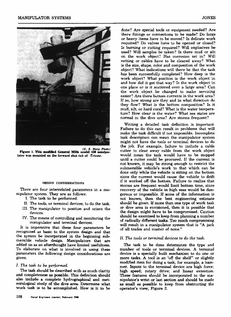
THE DEEP Ocean is a hostile environment. Beyond a few hundred feet surface light fades, then vanishes into perpetual darkness. Canyons sink down thou- sands of feet and abyssal planes extend for hundreds of miles. Bottom surfaces vary from hard coral to silt; currents from a fraction of a knot to four knots. Temperatures drop to near freezing and pressures rise at a rate of about one and a third tons per square inch for each thousand fathoms of depth. Even with the most advanced diving techniques, divers can do work down to only a few hundred feet. To go beyond this depth man must be encapsulated in the pressure hull of a deep submersible vehicle. Tc. do work in the ocean man must have mechanical a r m called manipulators. In 1961 the Navy installed a modified atomic hot
ccri manipulator on the TRIESTE vehicle, Figure 1.
This was the Navy’s first use of a manipulator on a manned deep submersible vehicle. As a result of this manipulator, Navy scientists could not only venture into the deep ocean, but also do a limited amount of specimen recovery work there. Since that time the number of the Navy’s deep Ocean work tasks has greatly expanded. The THRESHER search and the hydrogen bomb recovery at Palo- mares, Spain, emphasized the need for a more advanced manipulator system approach to the task of doing work in the ocean. Deep Ocean work by the 1970’s will involve such areas as salvage, con- struction, rescue, and oceanographic research. To meet the needs imposed by these work areas, a system approach for manipulators is required. This system approach will give man the means he needs to expand his knowledge of the ocean depths and to do useful work in that environment.
Naval Enqineen Journal, February IT68 107
MANIPULATOR SYSTEMS JONES
(U. S. Navy Photo) Figure 1. Thb modi6ed General Milla model 150 manipu-
lator was mounted on the forward shot tub of Trieste.
DESIGN CONSIDERATIONS
There are four interrelated parameters in a ma- nipulator system. They are as follows:
I. The task to be performed. 11. The tools, or terminal devices, to do the task.
111. The manipulator to position and orient the
IV. The means of controlling and monitoring the
It is imperative that these four parameters be recognized as basic to the system design and that the system be incorporated in the beginning sub- mersible vehicle design. Manipulators that are added on as an afterthought have limited usefulness. To elaborate on what is involved in using these parameters the following design considerations are given.
1. The task to be perjormed. The task should be described with as much clarity
and completeness as possible. This definition should also include a complete hydrographical and met- eorological study of the dive area. Determine what work task is to be accomplished. How is it to be
devices.
manipulator and terminal devices.
done? Are special tools or equipment needed? Are there fittings or connections to be made? Do large or heavy items have to be moved? Is delicate work required? Do valves have to be opened or closed? Is burning or cutting required? Will explosives be used? Will samples be taken? Is there mud or silt on the work object? Has corrosion set in? Will netting or cables have to be cleared away? What is the size, shape, color and composition of the work object? What indications will there be that the task has been successfully completed? How deep is the work object? What position is the work object in and how did it get that way? Is the work object in one place or is it scattered over a large area? Can the work object be changed to make servicing easier? Are there bottom currents in the work area? If so, how strong are they and in what direction do they flow? What is the bottom composition? Is it mud, silt, or hard coral? What is the water tempera- ture? How clear is the water? What sea states are normal in the dive area? Are storms frequent?
Writing a detailed task definition is important. Failure to do this can result in problems that will make the task difficult if not impossible. Incomplete task description can mean the manipulator system might not have the tools or terminal devices to do the job. For example, failure to include a cable cutter to clear away cable from the work object would mean the task would have to be stopped until a cutter could be procured. If the current is not known, it may be strong enough to restrict the submersible vehicle’s work to that which can be done only while the vehicle is sitting on the bottom since the current would cause the vehicle to drift if it worked off the bottom. Failure to realize that storms are frequent would limit bottom time, since recovery of the vehicle in high seas would be dan- gerous or impossible. If some of the information is not known, then the best engineering estimate should be given. If more than one type of work task or dive area is envisioned, then it is possible that the design might have to be compromised. Caution should be exercised to keep from plannmg a number of radically different tasks. Too much compromising will result in a manipulator system that is “A jack of all trades and master of none.”
11. The tools or terminal devices to do the task.
The task to be done determines the type and number of tools or terminal devices. A terminal device is a specially built mechanism to do one or more tasks. A tool is an ‘off the shelf” or slightly modified item for doing a task, for example, a ham- mer. Inputs to the terminal device are high force; high speed; rotary drive; and linear extention. These features should be incorporated in the ma- nipulator’s wrist or last section and should be made as small as possible to keep from obstructing the operator’s view, Figure 2.
108 Naval Enginwn Journal. hbru4t-y I9U

JONES MANIPULATOR SYSTEMS
/ /
i 6
\
Figure 2. Sketch of a possible arrangement of high force, high speed, rotary drive, and linear extention for tennhd
device. (North American Aviation Manipulator Report)
Considerations should be given to having the terminal device absorb some of its own reaction forces and torques. Unless this is done, the reaction tends to move the manipulator and vehicle. Making the manipulator large enough to absorb this reaction would give it an unwieldly size. A possible solution is to adapt some of the "zero reaction" tools that have been developed for use by astronauts in space. Since the amount of force required to do a task will vary depending on the Merent operations that have to be done, the operator should have means of controlling the amount of force the terminal device can exert. This can be incorporated in the control device.
If the task description shows that a relative few terminal devices or tools are required, then a special purpose terminal device that incorporates all the desired features should be built. An example of this is the terminal device for the Deep Submersible Rescue Vehicle (DSRV), Eigure 3. This terminal device is required to clear away debris from the stricken submarine's escape hatch and to handle and place the grapple which is used for rescue. For many work tasks a variety of terminal de-
vices will be needed. Since most submersible ve- hicles are powered by batteries, it would be an undesirable use of battery power to surface to ex- change terminal devices. Underwater tool or termi- nal device exchange then becomes necessary. To carry a number of tools or terminal devices, tool racks are required, Figure 4. The rack should not only h l y hold the tools against vibration during transit, but also allow enough room for the termi- nal devices to be exchanged without binding. Guides and springs can be used to assist the aline- ment necessary for the exchange. The linear exten- tion should be used in the exchange since this allows the operator to position the manipulator above the rack and extend the terminal device for an ex- change. It is imperative that good viewing be avail-
ntff.5 m u s n - , \ w
Figure 3. DSRV Terminal Device. (North American Aviation Manipulator Report)
F w e 4. A mock up of the AUTEC MPnIpulPtor SystCm showing M of the tool rack and ow of the two dpulators.
(General Dynomicr, Electric Boat DIvMon Photo)
able for the exchange since, otherwise, the terminal device might bind or miss the rack.
Because there are a number of terminal devices that can be built, the following discussion is in- cluded to describe some of them. The following sizes and forces are recommended if their values can not be determined from the task description.
Cable Cutter (Figure 5) The cable cutter may use mechanical or powder activated means of pow- ering the cutter blade. If powder activated means are used, the operator's control unit should have a two-step circuit to arm and fire the device. The powder activated device should be designed in such
Naval Enqinoon Journal, Fobwary IW 109

MANIPULATOR SYSTEMS JONES
(North American Aviation Manipuhtor Report)
Figure 5. Cable Cutter.
a way that the shock released from the explosion is contained within the device so that there is no danger of damaging viewpoint or other equipment. It is suggested that the cutter be sized to handle composite cables from Y’ inch to 3 inches in di- ameter and wire rope cables up to 1 inch in diameter. When cutting cables under strain, consid- eration should be given to the effects of whiplash. Tension in the cable can be determined by a ten- siometer. Either cable guides or some means of re- mote cutting such as a long handled cutter should be used for large tension values.
Hook Hand (Figure 6 ) The hook hand should be powered by the manipulator’s high force input. A suggested size would be minimum jaw opening of 2% inches with a 4 inch stroke. The force exerted should be adjustable with a suggested maximum of 2000 pounds. A jaw could be shaped to fit hexagon stock.
Parallel Jaw Hand (Figure 7 ) The parallel jaw hand should also be powered by the manipulator’s high force input. It is suggested that the hand have a 6-inch opening with an adjustable grip force up to 2000 pounds. Rubber inserts in the hand would enable it to grasp irregularly shaped objects.
Donance Type Prosthetic Hand (Figure 8 ) The prosthetic hand should be powered by the manipu- lator’s high force input. A suggested opening size is 4 inches with a 50-pound grip force. This hand is a scaled up version of the Dorrance hand.
Figure 7. Parallel Jaw Hand.
Clam She22 Hand (Figure 9) The clam shell hand should be powered by the manipulator’s high force input. A suggested mouth opening is 18 inches. Either two or three shells can be used.
Grapple Hand (Figure 10) The grapple hand should be powered by the manipulator’s high force input. A suggested opening is 12 inches with a 250-
110 Naval Enqinaen Journal. hbruary IT68

JONES MANIPULATOR SYSTEMS
GRID Rmcd AT KNC€
(North American Aviation Manipulator Report)
Figure 8. Dorrance Type Prosthetic Hand
--7-1 , - ?/'
1 I i'
pound grip force. The hand should be configured to pick up cylindrical objects.
Stud Gun (Figure 11) Powder activated devices are used to power stud guns and should have the same design characteristics as mentioned for the cable cutter. It is suggested that the gun be able to drive studs into steel plate up to ?4- inch thick. Studs can be either solid with a threaded end so an eye bolt can be screwed on, or hollow with a threaded
(North American Aviation Manipulator Report)
Figure 11. Stud Gun.
end so a valve'can be screwed on. A parallel jaw and the linear extension could be used to install the eye bolts and valves. Riveting can also be done with the stud gun. It would be desirable to design the gun so that the rivets could be loaded as cartridges. This would eliminate the need to surface for more rivets.
.! ,Lp- L' 1 Centrifugal Pump (Figure 12) The pump should be powered by the manipulator's high speed rota-
(North Maniplator Report) tion. The pump could have manually exchangeable heads for sucking or blowing. The pump should not exhaust into the viewports. A modified falcon nozzle can be used to reduce the reaction force.
-8.TtV6 - PI= r s
Figure 9. Clam Shell Hand
(Nor th American Aviation Manipulator Report)
Figure 10. Grapple Hand
(North American Adatbn Bfanipubtoz R W ) Figure 12. Centrihgd Pump.
Naval bqineen Journal, February IT60 111

MANIPULATOR SYSTEMS JONES
11
(General Dynamlcr, Electric Boat DiuWon Photo)
Figure 13. Stepped Drill Bit (Sketch of drill for the AUTEC Manipulator.
Drilling (Figure 13) The drill should use the manipulator's high force input for a power source. It is suggested that drill bits up to 1 inch in di- ameter be used. A stepped bit can be used, since it drills a pilot hole first.
Impact Tool (Figure 14) The high force input should be used to power a terminal device similar to an impact wrench. This terminal device could be used to install, tighten, and remove nuts and bolts varying in size up to 1% inches.
(North American A v f a h Manipulator Report)
Figure 15. Parallel jaw hand holding a hammer.
( N o r t h American Aviation Manipulator Report)
Figure 14. Impact Tool.
Saw Tool The high force input should be used to power a rotatory saw wheel for metal cutting. This tool would be useful in clearing away large objects such as masts up to 8 inches in diameter. The wheels should be expendable, since they are subject to wear. Blade guards should be used to prevent the blade from damaging the vehicle if the blade breaks. Reciprocating saws can be used, but they are more complicated to build.
Common tools, such as a hammer, can also be used. A useful terminal device to handle such a tool is the parallel jaw hand, Figure 15. Another example would be to use the parallel jaw to handle longnosed pliers; Figure 16.
III. THE MANIPULATOR TO POSITION AND ORIENT THlc TeRMINAL DEVICES
The number of manipulators and motions re- quired is dependent on the work task and the
number of terminal devices that are required to do the task. A manipulator system should be as simple as the task and terminal devices will allow. To build a more complex manipulator than is neces- sary is wasteful.
If the work task is simple and there are few terminal devices required, then a single manipu- lator with limited motion will do. It should be noted that the Diving Saucer SP-300 has been quite sue- cessful with its limited motion manipulator, Figure 17. Caution should be exercised, however, to keep from requiring too much in the way of motions and tasks from a simple system.
The system requires more than one manipulator and terminal device exchange ff the work task is complicated and requires a number of terminal de- vices. To position and orient terminal devices to do a complex task requires seven degrees of motion (three rotational, three translational, and linear ex- tention) of at least one of the manipulators. Provi- sion for more than one manipulator allows the submersible to work in a larger area without mov- ing. This is useful since time and battery power are required for each move the vehicle makes. If strong currents are present, then one of the manipulators might be used to hold on to the work object while the other does the task. This would be advantage- ous for off-the-bottom work, Figure 18.
For the simple manipulator either electrical or hydraulic power can be used to power the manipu-
112 Naval Enginmen Journal. hbruaw I T U

JONES MANIPULATOR SYSTEMS
Figure 16. Longnose pliers modified to fit a parallel jaw head.
lator. For the larger manipulators, which are re- quired to handle heavy objects, hydraulic power is recommended since a hydraulic motor is capable of developing a higher power per unit weight than a comparable electric motor. When the manipulator weight increases, the pay-load weight it can handle is decreased.
Safety is the most important consideration in manipulator design. Since there is a danger that manipulators may be entangled in an object that they are working on, for example becoming en- snared in cables or netting, the manipulators must have a jettison capability so that they may be disen- gaged and ejected clear of the vehicle. Disengage- ment of the manipulator should not allow seawater contamination of any hydraulic lines or shorting of any electrical conductors leading back into the ve- hicle. None of the vehicle's other functions should be impaired. Activation of the release device should be a deliberate two step operation to prevent in- advertent release. The release device should be op.?rable from at least two independent sources of pc.wer; for example an explosive activated device
Figure 17. Diving Saucer SP-300 with its manipulator.
that is fired by using either the main or emergencyl batteries. It is advisable that some means, such as detachable stops and electric circuit checks, be in- corporated in the release device, so that the release may be periodically checked without having to jet- tison the entire manipulator.
A second release device for the terminal device is advisable. Since the cost of terfninal devices is gen- erally much less than the cost of the manipulator, it would be advantageous to be able to jettison the terminal device rather than the entire manipulator if only the terminal device was entangled or locked on the work object. The same basic considerations as described for the manipulator release apply to the terminal device release.
If long distances are to be traversed while the vehicle is submerged, consideration should be given to stowing the manipulator in a protective fairing. This gives the vehicle a better hydrodynamic shape and reduces drag losses. If it is not possible to view
. I
' 1-
Figure 18. Off the bottom work using two manipulators.
Naval Engineers Journal, Februaw 1968 113

JONES MANIPULATOR SYSTEMS
the stowing of the manipulator, some means, such as contact switches and indicator lights, should be provided to indicate when the manipulator is stowed.
IV. THE MEANS OF CONTROLLING AND MONITORING THE MANIPULATOR AND TERMINAL DEVICES
The degree of sophistication of the control and monitoring equipment is dependent on how com- plex the system is. For the simple manipulators a push button or toggle switch control may be used, Figure 19. The control box should be small enough to fit into an operator’s hand, but large enough to provide enough space between buttons or switches so that the operator will not inadvertently move the wrong button or switch. Although toggle switches and push buttons can be used to control the termi- nal devices and manipulators used in complicated tasks, consideration should be given to position con- trol. Information concerning the manipulator’s po- sition, orientation, and the operation of the terminal device is fed back electrically to a control unit, generally a joystick, or miniature arm. The operator moves the control unit to the desired position and the manipulator duplicates this motion. Monitoring of the task is done by viewing the operation through viewports and TV monitors. The location of the viewports, external lights, and TV cameras should incorporate human factors techniques, that is, working with the manipulator should not cause un- due physical strain on the operator.
Direct viewing is preferred to TV monitors, al- though TV provides a useful aid. Pan and tilt mechanism should be used on TV cameras as this provides a wider field of view than stationary cam- eras. Selective use of lights can cause the object to cast a shadow thereby giving the manipulator op- erator a feeling of depth and size. If possible some of the light should come from in front of the view-
Figure 19. Push button control box.
114 Naval Engineers Journal. February 19U
port or TV camera and behind the work object so as to reduce the back scattering effect of plankton and water turbulence.
WORK TASKS To further explain the four parameters of manip-
ulator system design, (task, terminal devices, manipulators, and controls), a few examples of how Merent tasks could be accomplished will be given. The recovery of ordnance or other objects such as airplane wreckage would be a typical salvage task. This type of task would require more than one manipulator with a tool exchange capability. Posi- tion control would be most useful although a simple push button control could, with difficulty, be made to work. After the object is located, the first step in recovery is clearing and cleaning the work area.
In this type of work it is envisioned that the ve- hicle will operate while sitting on the bottom. If the object is large, it is possible that the vehicle may work off the bottom using one of the manipu- lators as a grapple to hang on to the object. This would steady the vehicle and help prevent it from drifting in the current. Continual use of propulsion to maintain position causes an unacceptable drain on battery power.
Often the object to be recovered is fouled by lines, cables, or debris. The R~COVERER I vehicle, for ex- ample, had to clear away fish nets when performing a salvage operation on a sunken fishing vesseL Use- ful tools for removing these things are the hook hand, the parallel jaw hand, and the prosthetic hand. The clam shell can be used, but because of its size, it may obstruct the operator’s view of the work.
Extreme care should be taken when moving such items as nets because there is danger of entangle- ment. The vehicle should work up current from the nets so that the current can carry the nets away from the vehicle. Cable cutters can be used when lines are too entangled or too long to drag clear. A bailing hook similar to those longshoremen use would be another useful tool.
For cleaning mud, sand, marine growth, and silt, a wire brush or centrifugal pump can be used. The wire brush can clear away marine growth while silt and mud can be removed with the pump. The pump would also be useful if the object is fragile. A second manipulator can be used to hold portable lights and cameras for close up investigation. It is advisable to use the hand-mounted television cam- eras only when the manipulator is stationary; viewing the monitor while the manipulator is in motion tends to make the observer dizzy.
After the object has been cleared of debris, ar- rangements are made to raise it. Small, light objects can be raised by direct lift using any of the hands previously described. Often, however, the object is too big or too heavy for a direct lift. In these cases, auxiliary means of lifting must be used.
If eye bolts, lifting rings, or padeyes are available

JONES MANIPULATOR SYSTEMS
(North American Aviation Manipulator Report)
Figure 20. Modified snap safety h d .
on the work object, the vehicle can use its manipu- lators to bring down a lift cable with a snaptype attachment device at the end. If eyebolts are not available they can be attached to the object by using the stud gun. This is useful for shallow depth lifts. An ordinary snap safety hook can be modified to serve as an attachment device, Figure 20. Small pieces of flat plate can be welded to the shank of the hook at right angles to the hook to serve as a gripping area. "his prevents the hook from rotating in transit. One manipulator can be used to handle the hook while the other is used to hold a guide sleeve for the cable. By running the cable through a sleeve, the risk of fouling it in the lift propeller or on the vehicle is minimized. If possible it is advis able that the final attachment of the hook to the padeye be done while the vehicle is sitting on the bottom. This provides greater stability.
For recovery of some objects, a net could be used. The net would be carried below the vehicle by the manipulator rather than as a termina€ device in the tool rack. Opening and closing of the net would be controlled by the manipulator. It is necessary for the object to be light enough in water so it can be picked up by the net. As soon as the object is en- closed in the net the manipulator could close the mmth of the net and then bring down a lift cable to attach to the net.
If the object is cylindrical, such as a torpedo, a gcod terminal device for recovery is the grapple hmd. For light objects the grapple hand can be u-?d as part of the manipulator; for heavier lifts it C; I, attached to a lift cable, be brought down from
the surface. For long objects, it is'suggested that two of the grapple hands be used in parallel with a strong-back as a spacer. Both grapples should be designed so that they can be attached at the same time.
There are problems involved with carrying a line down Current drag on the line makes it difficult to handle. One means of overcoming this problem is the use of the Hunley-Wischhoefer Messenger Buoy, Figure 21. The buoy consists of a spherical buoyancy chamber, messenger line, shot, connector, and con- nector release. The bottom connector is attached to a lift pendant. This pendant is connected to a lift pad containing velocity powered stud guns. After the buoy has been ballasted slightly positive using the ballast shot, the manipulator carries the buoy and pad down. When the vehicle approaches the object, the manipulator positions the buoy over the object, then lowers it until contact is made. Small magnets hold the lift pad in place until the vehicle can maneuver into a position beside the pad. At this time the manipulator, using the parallel jaw hand, pulls the lanyard on the stud guns to fire them. After firing the studs, the manipulator releases the buoy which surfaces, dropping out shot and paying out the messenger line.
On the surface, the messenger line is removed and fed through a specially constructed overshot sleeve, Figure 22. Attached to the sleeve is a heavy lift
Figure 21. The Hdey-Wkhhoefer -m Buoy.
Naval Engineers Journal, February I968 115

MANIPULATOR SYSTEMS JONES
Figure 22. The overshot sleeve for the Hunley-Wischhoefer Messenger Buoy.
Figure 24. Diving Seucer SP-300 carrying down the MGG system.
F I L L
F U E L
VALVE
T A N K
..
------
1- ~ \J ,RELIEF VALVE
ALVE
VALVE
VALVE
(V. S. Navy Photo)
Figure 23. The Mono-propellant Gas Generator System (MGG).
cable. Tension is taken on the messenger line and the overshot is allowed to slide down the line. When the overshot reaches the bottom, it attaches to the connector. The lift cable is now joined to the lift pad and the object can be r a i d . The present depth capability of this system is 850 feet, but it can be designed to work in deep waters by redesigning the buoyance chamber. The pad has a 25 ton lift ca- pability. There is also a 10-ton pad available.
Another auxiliary means of lifting objects is the m 26. The Alvin vehide’s manipulator with a core
sampler.
116 Naval Enqinnn Journal. February IW

JONES MANIPULATOR SYSTEMS
use of the hydrazine mono-propellant gas generator (MGG) system. This system mixes hydrazine from a fuel tank with a Shell 405 catalyst to decompose the fuel into hydrogen, nitrogen, and ammonia. This gas is used to inflate a lift bag, Figure 23. A grapple can be attached to the frame supporting the fuel tank.
The manipulator takes the system down, Figure 24. The parallel jaw hand is recommended as a tool for carrying although the clam shell hand would work. When in position, the manipulator clamps on the grapple. After the grapple is secured, the manipulator is used to fire the explosive valve. The valve allows the fuel to enter the MGG where the gas is generated and passes into the bag inflating it. Check valves are used to prevent back pressure. The inflated bag then raises the object to the sur- face. The MGG system has lifted objects weighing 200 pounds from depths of 1000 feet. Future ver- sions will provide 300 pounds of lift at 18,000 feet.
Oceanographic tasks are as varied as salvage tasks. To date some work has been done using sim- ple manipulator systems; however, if a great va- riety of tasks are envisioned, a complex manipula- tor system is merited.
Simple manipulator systems can be used for the placing and recovering of small instruments on the ocean bottom or the collecting of marine animal, plant, or geological samples, Figure 25. It can be assumed that these instruments and samples are up to 12 inches in diameter and 100 pounds in weight. It may also be assumed that at least some of the samples, such as marine animals and plants, are fragile. The terminal device can be either a parallel jaw hand or a two or three, fingered clam shell scoop.
The gathering of core samples would be a typical oceanographic task, Figure 26. The two types of core samplers are rotary type and punch type. The core device can be held in the parallel jaw terminal device. With tool exchange and a sample rack more than one sample can be taken. Punch type samples can be driven into the Ocean floor by free fall or forced in by making the vehicle negatively buoyant. Rotary samples can be taken with the high speed terminal device drive.
Other oceanographic tasks would be setting and replacing underwater arrays. Some consideration should be given in the design of the array so as to simplify the tasks the manipulator system would have to perform. A redesign approach has proven successful in the design of the underwater robots for offshore oil industry. The parallel jaw hand would be useful in taking the array down and bring- ing it up. If long submarine cables are involved, the array may have to be raised by auxiliary lifting neam as described in the previous discussion on salvage.
For some oceanographic and salvage tasks, ex- ilosives are required. Drilling tools, parallel jaw
Figure 27. A Piezoelectric Crystal used in a prosthetic hand.
hands, prosthetic hands, and clam shell hands are useful to assist in this work. The explosive charge should be made up before the dive and carried in the sample tray. At the work site the manipulator could use the drill or clam shell to dig holes around the object and place the charge with the parallel jaw hand or prosthetic hand. The vehicle would then surface and carry down the detonator and its cable. Two trips are recommended to minimize the danger of accidental detonation. It is recommended for safety that the vehicle return to the surface before the blast occurs. The charge can be set off by a signal from the surface.
FUTURE DEVELOPMENTS
Looking ahead to future manipulator systems, a great deal of work will be done in the sensors and control area. One thing lacking in the present manipulators is a feeling of touch. A possible means of achieving this sense is to adapt the piezoelectric crystal used in a prosthetic hand, Figure 27, devel- oped by Lloyd Salisbury and Albert Cerman of the U.S. Army Biomechanical Research Laboratory. When the object being retrieved slips, the crystal detects it and the hand automatically increases its grip until the slippage ceases. Another idea for im- provement of manipulator systems is placing the controls of the TV camera pan and tilt mechanism into a helmet to be worn by the operator. Move- ment of the operator’s head while watching the screen would move the camera. The screen should be far enough away from the operator’s head to prevent injury due to radiation from the TV screen. W e it is not suggested that this replace direct viewing, this camera arrangement would improve the operator’s view of the work,
In conclusion it can be stated that manipulator systems usage will increase. Spatial correspondence
MANIPULATOR SYSTEMS JONES
between the control unit and the manipulator will allow the operator more time to concentrate on the work task instead of on maneuvering the manipu- lators. More terminal devices will increase the sys- tem’s usefulnew. The ultimate goal is to have an operating manipulator system that has at least the capabilities of a diver, beyond diver depth.
ACKNOWLEDGMENTS The author wishes to thank the f o l l o e s o n s
who have provided information and suggestions for this paper, especially Mr. A. Twichell, Mr. W. Wischhoefer, Mr. W. Hunley, Mr. J. Breickner, and Mrs. Ellen Jones.
BIBLIOGFWPHY 1. Optimum Underwater Manipulator Systems for Manned Submersibles, Final Study Report 31 March 1966 North American Aviation Nobs Con- tract 92401 2. Existing Underwater Manipulators by W. Hun- ley and W. Houck ASME Publication no. 65 unit 8 March 17, 1965 3. A Mechanical Hand with Automatic Proportional Control Prehension Technical Report 6611 by Lloyd L. Salisbury and Albert B. Colman US. Army Medical Biomechanical Research Laboratory, Wal- ter Reed Medical Center, Washington, D.C. 20012 4. Underwater Buoyancy Systems NOTS TP 4100- 5 Part 4
USS. DUBUQUE Ssa trial photograph of USS Dubugue (LPD-8)’ a new type amphibious warfare ship daiped to add new dimension to the Navy’s troop and vehicle lift capability. She is a direct dacmdent of tbe Landing Ship Dock (ISD) of WW II and incorponted the features of the Attack Transport (APA), Attack Cargo Ship (AKA), and amphibious Assault Helicopter (LPH).
118 Naval Enqinaarr Journal. Fabruaw 1968