manifold catalog - dc-us.resource.bosch.com automation mobile hydraulics industrial hydraulics...
TRANSCRIPT

Manifold Catalog


ServiceAutomation
MobileHydraulics
IndustrialHydraulics
Electric Drivesand Controls
Linear Motion andAssembly Technologies Pneumatics
Rexroth Manifolds RA 09 907/07.04
The Drive & Control Company
Rexroth is also a manufacturerof customized manifolds.
We design, machine, assemble,and test to your application.
Engineered to your application,supplied from your single sourcespecialist.
Manifold System Solutions fromThe Drive & Control Company.
For more details
Call 1-800-REXROTH(739-7684)
or visit us on the web atwww.boschrexroth-us.com
Specifications, descriptions, and dimensional data are subject to cor-rection or change without notice or incurring obligation.
These drawings are for reference only. Please consult the appropriate stan-dard when dimensions are critical. Some holes are added per industry con-vention. Dimensions may vary on our products. It should not be assumedthat each hole shown is found on a given product.


ServiceAutomation
MobileHydraulics
IndustrialHydraulics
Electric Drivesand Controls
Linear Motion andAssembly Technologies Pneumatics
– Section 1. Bar Manifolds ............................................................................................................................................. 1
– Section 2. Subplates ..................................................................................................................................................31
– Section 3. Coverplates ..............................................................................................................................................43
– Section 4. Sandwich Plates .....................................................................................................................................49
– Section 5. Valve Adaptors ........................................................................................................................................57
– Section 6. Pump Manifolds .......................................................................................................................................73
– Section 7. Logic Manifolds .......................................................................................................................................85
– Section 8. Compact Bodies .....................................................................................................................................91
– Section 9. Compact Sandwich ................................................................................................................................99
– Section 10. Header and Junction Blocks ............................................................................................................. 103
– Section 11. Pre-engineered Circuit Solutions ..................................................................................................... 109
– Section 12. Technical Information .......................................................................................................................... 139
Table of Contents


The Drive & Control Company
ServiceAutomation
MobileHydraulics
IndustrialHydraulics
Electric Drivesand Controls
Linear Motion andAssembly Technologies Pneumatics
Section 1Bar Manifolds
RA 09 907/07.04
1
Bar Manifold Features
– Sizes 6 to 22
– Aluminum and ductile iron
– Side or bottom ported
– SAE, NPT, and BSPP porting, flanged ports for larger sizes
– Includes mounting kit
– Other accessories available
Note: Bar manifolds may be purchased as complete assembliesupon request

2/148 Bosch Rexroth Corp. Industrial Hydraulics Section 1: Bar Manifolds RA 09 907/07.04
Section 01 Index
Description Page
Bar Manifold D03 (Size 6) Parallel Circuit Normal Flow ................................................................................................................................................. 3
Bar Manifold D03 (Size 6) Paarallel Circuit HIgh Flow ................................................................................................................................................... 4
Bar Manifold D03 (Size 6) Parallel Circuit Normal Flow with DBDS Cavity .............................................................................................................. 5
Bar Manifold D03 (Size 6) Series Circuit Normal Flow .................................................................................................................................................. 6
Bar Manifold D05 (Size 10) Parallel Circuit Normal Flow .............................................................................................................................................. 7
Bar Manifold D05 (Size 10) Parallel Circuit High Flow with X & Y .............................................................................................................................. 8
Bar Manifold D05 (Size 10) Parallel Circuit Ultra High Flow .........................................................................................................................................9
Bar Manifold D05 (Size 10) Parallel Circuit Normal Flow with DBDS Cavity ......................................................................................................... 10
Bar Manifold D05 (Size 10) Parallel Circuit Extra High Flow with X & Y ................................................................................................................. 11
Bar Manifold D05 (Size 10) Series Circuit Normal Flow ............................................................................................................................................. 12
Bar Manifold D07 (Size 16) Parallel Circuit Normal Flow ........................................................................................................................................... 13
Bar Manifold D07 (Size 16) Parallel Circuit High Flow ................................................................................................................................................ 14
Bar Manifold D07 (Size 16) Parallel Circuit Extra High Flow ..................................................................................................................................... 15
Bar Manifold D08 (Size 22/25) Parallel Circuit Normal Flow ..................................................................................................................................... 16
Bar Manifold D08 (Size 22/25) Parallel Circuit Extra High Flow ............................................................................................................................... 17
Automotive Bar Manifold D03 (Size 6) Parallel Circuit Low Flow ............................................................................................................................. 18
Automotive Bar Manifold D03 (Size 6) Parallel Circuit Normal Flow ........................................................................................................................ 19
Automotive Bar Manifold D03 (Size 6) Parallel Circuit High Flow with ISO 6149 Ports .................................................................................... 20
Automotive Bar Manifold D03 (Size 6) Parallel Circuit Normal Flow Bottom Ported P&T .................................................................................. 21
Automotive Bar Manifold D05 (Size 10) Parallel Circuit Low Flow ........................................................................................................................... 22
Automotive Bar Manifold D05 (Size 10) Parallel Circuit Normal Flow ..................................................................................................................... 23
Automotive Bar Manifold D05 (Size 10) Parallel Circuit High Flow with ISO 6149 Ports .................................................................................. 24
Automotive Bar Manifold D05 (Size 10) Parallel Circuit Normal Flow Bottom Ported P&T ................................................................................ 25
Automotive Bar Manifold D08 (Size 22/25) Parallel Circuit Normal Flow ............................................................................................................... 26
ISO Bar Manifold D03 (Size 6) Parallel Circuit Normal Flow ..................................................................................................................................... 27
ISO Bar Manifold D05 (Size 10) Parallel Circuit Normal Flow ................................................................................................................................... 28
Mounting Accessories .......................................................................................................................................................................................................... 29
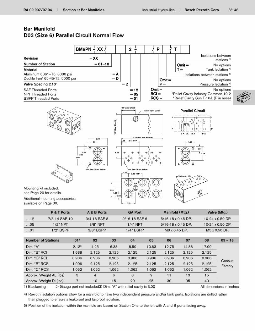
RA 09 907/07.04 Section 1: Bar Manifolds Industrial Hydraulics Bosch Rexroth Corp. 3/148
Isolations betweenstations 5)
Omit =Omit =Omit =Omit =Omit = No optionsT =T =T =T =T = Tank Isolation 4)
Isolations between stations 5)
Omit =Omit =Omit =Omit =Omit = No optionsP P P P P = Pressure Isolation 4)
OmitOmitOmitOmitOmit = No optionsRCIRCIRCIRCIRCI = *Relief Cavity Industry Common 10-2RCSRCSRCSRCSRCS = *Relief Cavity Sun T-10A (P in nose)
P & T Ports A & B Ports GA Port Manifold (Mtg.) Valve (Mtg.)
…12 7/8-14 SAE-10 3/4-16 SAE-8 9/16-18 SAE-6 5/16-18 x 0.45 DP. 10-24 x 0.50 DP.
…05 1/2” NPT 3/8” NPT 1/4” NPT 5/16-18 x 0.45 DP. 10-24 x 0.50 DP.
…01 1/2” BSPP 3/8” BSPP 1/4” BSPP M8 x 0.45 DP. M5 x 0.50 DP.
Mounting kit included,see Page 29 for details.
Additional mounting accessoriesavailable on Page 30.
Revision = XXXXXXXXXX
Number of Station = 01–1601–1601–1601–1601–16
MaterialAluminum 6061–T6, 3000 psi = AAAAADuctile Iron1 65-45-12, 5000 psi = DDDDD
Valve Spacing 2.13” = 22222
SAE Threaded Ports = 12= 12= 12= 12= 12NPT Threaded Ports = 05= 05= 05= 05= 05BSPP Threaded Ports = 01= 01= 01= 01= 01
BM6PN – XX / 2 – / P / T
"C"
(See
Ch
art)
"B" (see Chart)
See Chart Below
Relief Valve Cavity
GA
3.00
See Chart Below
TP
TP
GA
A
B
A
B
A
B
2.381.50
0.63
2.13
2.13 TYP1.06
2.19
0.81
1.50
1.842.69
0.31
3.00
0.31
"A" (See Chart Below)
2.13 TYP.66
T
P
B A B A B A
T
P
Station #1 (5)
Parallel Circuit
Number of Stations 012 02 03 04 05 06 07 08 09 – 16
Dim. “A” 2.133 4.25 6.38 8.50 10.63 12.75 14.88 17.00
Dim. “B” RCI 1.688 2.125 2.125 2.125 2.125 2.125 2.125 2.125
Dim. “C” RCI 0.906 0.906 0.906 0.906 0.906 0.906 0.906 0.906Consult
Dim. “B” RCS 1.906 2.125 2.125 2.125 2.125 2.125 2.125 2.125 FactoryDim. “C” RCS 1.062 1.062 1.062 1.062 1.062 1.062 1.062 1.062
Approx. Weight AL (lbs) 3 4 6 8 9 11 13 15
Approx. Weight DI (lbs) 7 10 15 20 25 30 35 40
1) Blackening 2) Gauge port not included3) Dim. “A” with relief cavity is 3.00 All dimensions in inches
4) Rexroth isolation options allow for a manifold to have two independent pressure and/or tank ports. Isolations are drilled ratherthan plugged to ensure a leakproof and failproof isolation.
5) Position of the isolation within the manifold are based on Station One to the left with A and B ports facing away.
Bar ManifoldD03 (Size 6) Parallel Circuit Normal Flow

4/148 Bosch Rexroth Corp. Industrial Hydraulics Section 1: Bar Manifolds RA 09 907/07.04
Number of Stations 012 02 03 04 05 06 07 08 09 – 10
Dim. “A” 3.13 5.25 7.38 9.50 11.63 13.75 15.88 18.00Consult
Approx. Weight AL (lbs) 5 8 12 15 18 22 25 28 FactoryApprox. Weight DI (lbs) 13 18 31 40 48 57 66 75
1) Blackening 2) Gauge port not included
RevisionRevisionRevisionRevisionRevision = XX= XX= XX= XX= XX
Number of StationNumber of StationNumber of StationNumber of StationNumber of Station = 01–10= 01–10= 01–10= 01–10= 01–10
MaterialMaterialMaterialMaterialMaterialAluminum 6061–T6, 3000 psi = A= A= A= A= ADuctile Iron1 65-45-12, 5000 psi = D= D= D= D= D
PortsPortsPortsPortsPorts12 =12 =12 =12 =12 = SAE Threaded Ports01 =01 =01 =01 =01 = BSPP Threaded Ports
2 =2 =2 =2 =2 = Valve Spacing 2.13”Valve Spacing 2.13”Valve Spacing 2.13”Valve Spacing 2.13”Valve Spacing 2.13”
BM6PH – XX / 2 –
See Chart BelowSee Chart Below
1.00
2.81
2.002.13 (TYP.)
"A" (See Chart Below)
1.16
1.56
4.000.31
0.31
3.69
4.00
2.13 (TYP.)
2.00
3.13
0.88
1.56
2.63
T
P
ABAGAAB B
T
P
TPPT
B
A
B
A
GA
A
B
All dimensions in inches
T Port A, B, & P Ports GA Port Manifold (Mtg.) Valve (Mtg.)
…12 1-5/16-12 SAE-16 1-1/16-12 SAE-12 9/16-18 SAE-6 5/16-18 x 0.45 DP. 10-24 x 0.50 DP.
…01 1” BSPP 3/4” BSPP 1/4” BSPP M8 x 0.45 DP. M5 x 0.50 DP.
Mounting kit included,see Page 29 for details.
Additional mounting accessoriesavailable on Page 30.
Parallel Circuit
Bar ManifoldD03 (Size 6) Parallel Circuit High Flow
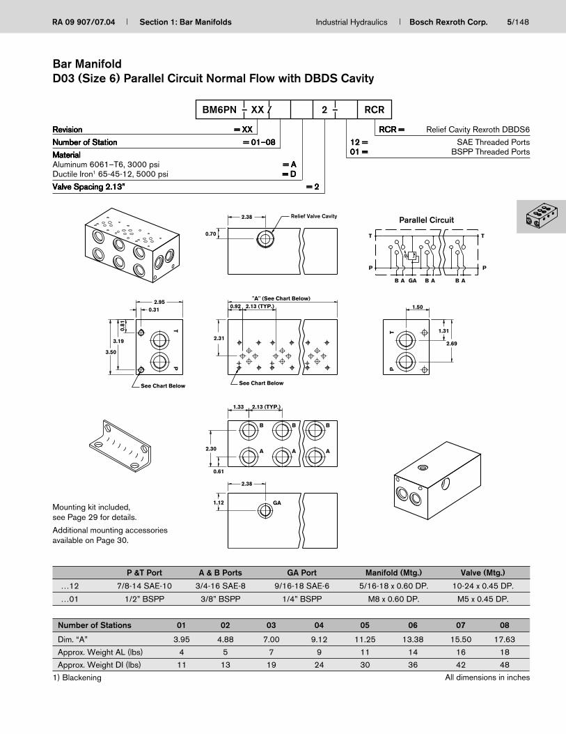
RA 09 907/07.04 Section 1: Bar Manifolds Industrial Hydraulics Bosch Rexroth Corp. 5/148
Number of Stations 01 02 03 04 05 06 07 08
Dim. “A” 3.95 4.88 7.00 9.12 11.25 13.38 15.50 17.63
Approx. Weight AL (lbs) 4 5 7 9 11 14 16 18
Approx. Weight DI (lbs) 11 13 19 24 30 36 42 48
1) Blackening
2.13 (TYP.)
GA
A
BB
AA
B
TP
TP
0.61
0.31
3.50
2.13 (TYP.)
1.12
2.38
2.30
3.19
0.81
1.33
2.31
2.950.92
0.70
2.38
"A" (See Chart Below)
1.50
2.69
1.31
TT
P
AB GA AB AB
P
Relief Valve Cavity
See Chart Below See Chart Below
Parallel Circuit
RevisionRevisionRevisionRevisionRevision = XX= XX= XX= XX= XX
Number of StationNumber of StationNumber of StationNumber of StationNumber of Station = 01–08= 01–08= 01–08= 01–08= 01–08
MaterialMaterialMaterialMaterialMaterialAluminum 6061–T6, 3000 psi = A= A= A= A= ADuctile Iron1 65-45-12, 5000 psi = D= D= D= D= D
Valve Spacing 2.13”Valve Spacing 2.13”Valve Spacing 2.13”Valve Spacing 2.13”Valve Spacing 2.13” = 2= 2= 2= 2= 2
RCR =RCR =RCR =RCR =RCR = Relief Cavity Rexroth DBDS6
12 =12 =12 =12 =12 = SAE Threaded Ports01 =01 =01 =01 =01 = BSPP Threaded Ports
BM6PN – XX / 2 – RCR
P &T Port A & B Ports GA Port Manifold (Mtg.) Valve (Mtg.)
…12 7/8-14 SAE-10 3/4-16 SAE-8 9/16-18 SAE-6 5/16-18 x 0.60 DP. 10-24 x 0.45 DP.
…01 1/2” BSPP 3/8” BSPP 1/4” BSPP M8 x 0.60 DP. M5 x 0.45 DP.
All dimensions in inches
Bar ManifoldD03 (Size 6) Parallel Circuit Normal Flow with DBDS Cavity
Mounting kit included,see Page 29 for details.
Additional mounting accessoriesavailable on Page 30.

6/148 Bosch Rexroth Corp. Industrial Hydraulics Section 1: Bar Manifolds RA 09 907/07.04
RevisionRevisionRevisionRevisionRevision = XX= XX= XX= XX= XX
Number of StationNumber of StationNumber of StationNumber of StationNumber of Station = 02–08= 02–08= 02–08= 02–08= 02–08
MaterialMaterialMaterialMaterialMaterialAluminum 6061–T6, 3000 psi = A= A= A= A= ADuctile Iron1 65-45-12, 5000 psi = D= D= D= D= D
Valve Spacing 2.13”Valve Spacing 2.13”Valve Spacing 2.13”Valve Spacing 2.13”Valve Spacing 2.13” = 2= 2= 2= 2= 2
Omit =Omit =Omit =Omit =Omit = No OptionsRCI =RCI =RCI =RCI =RCI = Relief Cavity Industry
Common 10-2RCS =RCS =RCS =RCS =RCS = Relief Cavity Sun T-10A
(P in nose)
12 =12 =12 =12 =12 = SAE Threaded PortsP&T: 7/8-14 SAE-10A&B: 3/4-16 SAE-8GA: 9/16-18 SAE-6
BM6SN – XX / 2 –
Number of Stations 02 03 04 05 06 07 08
Dim. “A” 4.25 6.38 8.50 10.63 12.75 14.88 17.00
Approx. Weight AL (lbs) 4 6 8 9 11 13 15
Approx. Weight DI (lbs) 10 15 20 25 30 35 40
1) Blackening
10-24 X 0.50 DP. (TYP.)
3.00
(2) 5/16-18 x .45 DP.
TP
TP
GA
A
B
A
B
A
B
2.38
1.500.63
2.13
2.13 TYP1.06
2.19
0.81
1.50
1.842.69
0.31
3.00
0.31
"A" (See Chart Below)
2.13 TYP.66
2.13
0.90
Relief Valve CavitySeries Circuit
GA
T
P
B A B A B A
T
P
All dimensions in inches
Bar ManifoldD03 (Size 6) Series Circuit Normal Flow
Mounting kit included,see Page 29 for details.
Additional mounting accessoriesavailable on Page 30.

RA 09 907/07.04 Section 1: Bar Manifolds Industrial Hydraulics Bosch Rexroth Corp. 7/148
Isolations betweenstations 5)
Omit =Omit =Omit =Omit =Omit = No optionsT =T =T =T =T = Tank Isolation 4)
Isolations between stations 5)
Omit =Omit =Omit =Omit =Omit = No optionsP =P =P =P =P = Pressure Isolation 4)
Omit =Omit =Omit =Omit =Omit = No optionsRCI =RCI =RCI =RCI =RCI = Relief Cavity Industry Common 10-2RCS =RCS =RCS =RCS =RCS = Relief Cavity Sun T-3A
(P in nose)
RevisionRevisionRevisionRevisionRevision = XX= XX= XX= XX= XX
Number of StationNumber of StationNumber of StationNumber of StationNumber of Station = 01–12= 01–12= 01–12= 01–12= 01–12
MaterialMaterialMaterialMaterialMaterialAluminum 6061–T6, 3000 psi = A= A= A= A= ADuctile Iron1 65-45-12, 5000 psi = D= D= D= D= D
Valve Spacing 3.25”Valve Spacing 3.25”Valve Spacing 3.25”Valve Spacing 3.25”Valve Spacing 3.25” = 3= 3= 3= 3= 3
PortsPortsPortsPortsPortsSAE Threaded Ports = 12= 12= 12= 12= 12NPT Threaded Ports = 05= 05= 05= 05= 05BSPP Threaded Ports = 01= 01= 01= 01= 01
BM10PN – XX / 3 – / P / T
P & T Ports A & B Ports GA Port Manifold (Mtg.) Valve (Mtg.)
…12 1-1/16-12 SAE-12 3/4-16 SAE-8 9/16-18 SAE-6 5/16-18 x 0.60 DP. 1/4-20 x 0.60 DP.
…05 3/4” NPT 1/2” NPT 1/4” NPT 5/16-18 x 0.60 DP. 1/4-20 x 0.60 DP.
…01 3/4” BSPP 1/2” BSPP 3/8” BSPP M8 x 0.60 DP. M6 x 0.60 DP.
Number of Stations 012 02 03 04 05 06 07 08 – 12
Dim. “A” 3.25 w/o relief 6.50 9.75 13.00 16.25 19.50 22.754.50 w/relief
Dim. “B” RCI 2.688 2.688 2.688 2.688 2.688 2.688 2.688 ConsultDim. “B” RCS 2.406 2.406 2.406 2.406 2.406 2.406 2.406 Factory
Approx. Weight AL (lbs) 5 8 12 16 20 23 27
Approx. Weight DI (lbs) 14 21 31 41 52 62 72
1) Blackening 2) Gauge port not included All dimensions in inches
Bar ManifoldD05 (Size 10) Parallel Circuit Normal Flow
"B" (See Chart)
3.25
3.502.94
0.56
3.500.31
2.81
1.750.69
3.19
3.25 TYP1.56
2.19
"A" (See Chart Below)3.25 TYP2.28 1.75
2.62
0.88
Parallel CircuitRelief valve cavity
See Chart Below
GA
See Chart Below
PT
B
A A
B
A
B
GA
TP
T
P
BBABA A
T
P
Station #1 (5)
Mounting kit included,see Page 29 for details.
Additional mounting accessoriesavailable on Page 30.
4) Rexroth isolation options allow for a manifold to have two independent pressure and/or tank ports. Isolations are drilled ratherthan plugged to ensure a leakproof and failproof isolation.
5) Position of the isolation within the manifold are based on Station One to the left with A and B ports facing away.
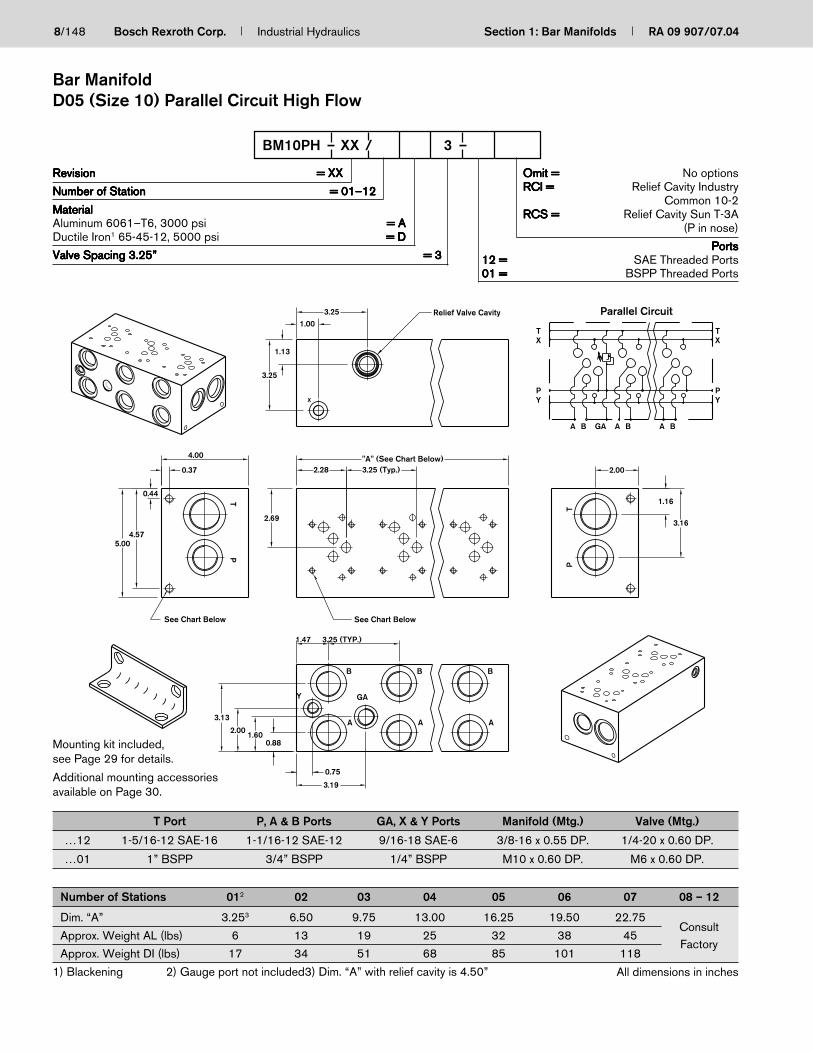
8/148 Bosch Rexroth Corp. Industrial Hydraulics Section 1: Bar Manifolds RA 09 907/07.04
Number of Stations 012 02 03 04 05 06 07 08 – 12
Dim. “A” 3.253 6.50 9.75 13.00 16.25 19.50 22.75Consult
Approx. Weight AL (lbs) 6 13 19 25 32 38 45Factory
Approx. Weight DI (lbs) 17 34 51 68 85 101 118
1) Blackening 2) Gauge port not included3) Dim. “A” with relief cavity is 4.50”
RevisionRevisionRevisionRevisionRevision = XX= XX= XX= XX= XX
Number of StationNumber of StationNumber of StationNumber of StationNumber of Station = 01–12= 01–12= 01–12= 01–12= 01–12
MaterialMaterialMaterialMaterialMaterialAluminum 6061–T6, 3000 psi = A= A= A= A= ADuctile Iron1 65-45-12, 5000 psi = D= D= D= D= D
Valve Spacing 3.25”Valve Spacing 3.25”Valve Spacing 3.25”Valve Spacing 3.25”Valve Spacing 3.25” = 3= 3= 3= 3= 3
Omit =Omit =Omit =Omit =Omit = No optionsRCI =RCI =RCI =RCI =RCI = Relief Cavity Industry
Common 10-2RCS =RCS =RCS =RCS =RCS = Relief Cavity Sun T-3A
(P in nose)
PortsPortsPortsPortsPorts12 =12 =12 =12 =12 = SAE Threaded Ports01 =01 =01 =01 =01 = BSPP Threaded Ports
BM10PH – XX / 3 –
T Port P, A & B Ports GA, X & Y Ports Manifold (Mtg.) Valve (Mtg.)
…12 1-5/16-12 SAE-16 1-1/16-12 SAE-12 9/16-18 SAE-6 3/8-16 x 0.55 DP. 1/4-20 x 0.60 DP.
…01 1” BSPP 3/4” BSPP 1/4” BSPP M10 x 0.60 DP. M6 x 0.60 DP.
Parallel CircuitRelief Valve Cavity
1.13
3.25
TX
PY Y
X
P
T
A BBAGABA
X
See Chart Below
Y
B
A
B
A
GA
B
A
TP
TP
See Chart Below
2.00
1.16
3.16
1.00
3.25 (Typ.)"A" (See Chart Below)
3.25
2.28
2.69
3.25 (TYP.)1.47
3.19
0.75
2.00
3.13
1.600.88
0.37
4.00
0.44
4.575.00
All dimensions in inches
Bar ManifoldD05 (Size 10) Parallel Circuit High Flow
Mounting kit included,see Page 29 for details.
Additional mounting accessoriesavailable on Page 30.

RA 09 907/07.04 Section 1: Bar Manifolds Industrial Hydraulics Bosch Rexroth Corp. 9/148
Number of Stations 02 03 04 05 06
Dim. “A” 7.00 10.25 13.50 16.75 20.00
Dim. “B” — 3.25 6.50 9.75 13.00
Approx. Weight DI (lbs) 36 53 70 87 104
1) Blackening
(2) 5/16-18 x .55 DP. (4) ؔ0.281 Drill Thru (Mtg.)1/4-20 x 0.60 DP. (TYP).
2.451.25
1.20
3.20
P
T
"B"
"A" (See Chart Below)
3.25(TYP.)
2.533.50
0.354.104.45
0.35
4.15
2.68
T
2.500.35
4.15
4.50
P
B
A
B
3.25 (TYP.)
B
1.83
1.35
A A3.55
P
A B
T
A BBA
P
T
Mounting kit not included.
Parallel Circuit
RevisionRevisionRevisionRevisionRevision = XX= XX= XX= XX= XX
Number of StationNumber of StationNumber of StationNumber of StationNumber of Station = 02–06= 02–06= 02–06= 02–06= 02–06
MaterialMaterialMaterialMaterialMaterialDuctile Iron1 65-45-12 = D= D= D= D= D5000 psi / 34.5 MPa
Valve Spacing 3.25”Valve Spacing 3.25”Valve Spacing 3.25”Valve Spacing 3.25”Valve Spacing 3.25” = 3= 3= 3= 3= 3
12 =12 =12 =12 =12 = SAE Threaded PortsT: 1 5/8-12 SAE-20P: 1 5/16-12 SAE-16A&B: 1 1/16-12 SAE-12
BM10PU – XX / D 3 –
All dimensions in inches
Bar ManifoldD05 (Size 10) Parallel Circuit Ultra High Flow

10/148 Bosch Rexroth Corp. Industrial Hydraulics Section 1: Bar Manifolds RA 09 907/07.04
Number of Stations 01 02 03 04 05 06 07
Dim. “A” 5.00 6.88 10.13 13.38 16.63 19.88 23.13
Approx. Weight AL (lbs) 10 13 20 24 32 39 45
Approx. Weight DI (lbs) 26 35 52 64 86 102 120
1) Blackening
RevisionRevisionRevisionRevisionRevision = XX= XX= XX= XX= XX
Number of StationNumber of StationNumber of StationNumber of StationNumber of Station = 01–07= 01–07= 01–07= 01–07= 01–07
MaterialMaterialMaterialMaterialMaterialAluminum 6061–T6, 3000 psi = A= A= A= A= ADuctile Iron1 65-45-12, 5000 psi = D= D= D= D= D
Valve Spacing 3.25”Valve Spacing 3.25”Valve Spacing 3.25”Valve Spacing 3.25”Valve Spacing 3.25” = 3= 3= 3= 3= 3
RCR =RCR =RCR =RCR =RCR = Relief Cavity Rexroth DBDS10
12 =12 =12 =12 =12 = SAE Threaded Ports01 =01 =01 =01 =01 = BSPP Threaded Ports
BM10PN – XX / 3 – RCR
"A" (See Chart Below)
1.52
3.25
3.25 (TYP.)2.31
2.58
3.25
4.11
2.95
1.89
3.25 (TYP.)1.65
3.07
1.32
3.00
3.95
3.14
0.76
4.950.31
TPP
T
B
A
B
A
B
A
GA
See Chart BelowSee Chart Below
T
A B
P
T
A B A BGA
P
Parallel Circuit
P & T Port A & B Ports GA Ports Manifold (Mtg.) Valve (Mtg.)
…12 1-1/16-12 SAE-12 1-1/16-12 SAE-12 9/16-18 SAE-6 5/16-18 x 0.65 DP. 1/4-20 x 0.60 DP.
…01 3/4” BSPP 3/4” BSPP 1/4” BSPP M8 x 0.65 DP. M6 x 0.60 DP.
All dimensions in inches
Bar ManifoldD05 (Size 10) Parallel Circuit Normal Flow with DBDS Cavity
Mounting kit included,see Page 29 for details.
Additional mounting accessoriesavailable on Page 30.

RA 09 907/07.04 Section 1: Bar Manifolds Industrial Hydraulics Bosch Rexroth Corp. 11/148
5.00
1.00
0.71
See Chart BelowSee Chart Below
3.23
1.13
2.15
3.66
0.71
3.87
2.91
2.00
1.13
3.25 TYP.2.03
2.68
"A" (See Chart Below)
3.25 TYP.2.80
1.00
4.00
4.56
0.44
5.00
0.38
TX
PY Y
X
P
T
A BBAGABA
TP
B
A
B
AY
GA
A
XX
TP
Y
B
RevisionRevisionRevisionRevisionRevision = XX= XX= XX= XX= XX
Number of StationNumber of StationNumber of StationNumber of StationNumber of Station = 01–06= 01–06= 01–06= 01–06= 01–06
MaterialMaterialMaterialMaterialMaterialAluminum 6061-T6, 3000 psi = A= A= A= A= ADuctile Iron1 65-45-12, 5000 psi = D= D= D= D= D
Valve Spacing 3.25”Valve Spacing 3.25”Valve Spacing 3.25”Valve Spacing 3.25”Valve Spacing 3.25” = 3= 3= 3= 3= 3
12 =12 =12 =12 =12 = SAE Threaded Ports01 =01 =01 =01 =01 = BSPP Threaded Ports
BM10PX – XX / 3 –
Number of Stations 012 02 03 04 05 06
Dim. “A” 4.25 7.50 10.75 14.00 17.25 20.50
Approx. Weight AL (lbs) 10 18 26 34 42 50
Approx. Weight DI (lbs) 27 48 69 91 112 133
1) Blackened 2) Gauge port not included
T Port P + A & B Ports GA, X & Y Ports Manifold (Mtg.) Valve (Mtg.)
…12 1-5/8-12 SAE-20 1-5/16-12 SAE-16 9/16-18 SAE-6 3/8-16 x 0.60 DP. 1/4-20 x 0.60 DP.
…01 1-1/4” BSPP 1” BSPP 1/4” BSPP M10 x 0.60 DP. M6 x 0.60 DP.
Parallel Circuit
All dimensions in inches
Bar ManifoldD05 (Size 10) Parallel Circuit Extra High Flow with X & Y Ports
Mounting kit included,see Page 29 for details.
Additional mounting accessoriesavailable on Page 30.

12/148 Bosch Rexroth Corp. Industrial Hydraulics Section 1: Bar Manifolds RA 09 907/07.04
RevisionRevisionRevisionRevisionRevision = XX= XX= XX= XX= XX
Number of StationNumber of StationNumber of StationNumber of StationNumber of Station = 02–04= 02–04= 02–04= 02–04= 02–04
MaterialMaterialMaterialMaterialMaterialAluminum 6061-T6, 3000 psi = A= A= A= A= ADuctile Iron1 65-45-12, 5000 psi = D= D= D= D= D
Valve Spacing 3.25”Valve Spacing 3.25”Valve Spacing 3.25”Valve Spacing 3.25”Valve Spacing 3.25” = 3= 3= 3= 3= 3
Omit =Omit =Omit =Omit =Omit = No OptionsRCI =RCI =RCI =RCI =RCI = Relief Cavity Industry
Common 10-2RCS =RCS =RCS =RCS =RCS = Relief Cavity Sun T-3A
(P in nose)
12 =12 =12 =12 =12 = SAE Threaded Ports
BM10SN – XX / 3 –
Number of Stations 02 03 04
Dim. “A” 6.50 9.75 13.00
Approx. Weight AL (lbs) 8 12 16
Approx. Weight DI (lbs) 20 31 41
1) Blackening
P & T Ports A & B Ports GA Ports Manifold (Mtg.) Valve (Mtg.)
…12 1-1/16-12 SAE-12 3/4-16 SAE-8 9/16-18 SAE-6 5/16-18 x 0.50 DP. 1/4-20 x 0.60 DP.
2.19
1.75
1.75
3.25
3.50 2.
94 0.56
3.500.31
2.81
1.75
0.69 2.50
3.25 TYP1.56
1.75
"A" See chart below3.25 TYP2.28 1.75
0.75
Series Circuit
Series Circuit
Relief Cavity
T
A BB GAA
P
See chart below
GA
See chart below
P
B
A A
B
A
B
GA
T
T
BBABA A
P
All dimensions in inches
Bar ManifoldD05 (Size 10) Series Circuit Normal Flow
Mounting kit included,see Page 29 for details.
Additional mounting accessoriesavailable on Page 30.

RA 09 907/07.04 Section 1: Bar Manifolds Industrial Hydraulics Bosch Rexroth Corp. 13/148
Number of Stations 012 02 03 04 05 06
Dim. “A” 4.033 8.00 12.00 16.00 20.00 24.00
Dim. “B” RCI 3.20 3.20 3.20 3.20 3.20 3.20
Dim. “B” RCS 3.25 3.25 3.25 3.25 3.25 3.25
Approx. Weight AL (lbs) 11/143 21 32 43 53 64
Approx. Weight DI (lbs) 28/383 56 84 112 140 168
1) Blackening 2) Gauge port not included 3) Dim. “A” with relief cavity is 5.50”
T Port P + A & B Ports GA, X & Y Ports Manifold (Mtg.) Valve (Mtg.)
…12 1-5/16-12 SAE-16 1-1/16-12 SAE-12 9/16-18 SAE-6 3/8-16 x 0.75 DP.3/8-16 x 0.70 DP.1/4-20 x 0.75 DP.
…05 1” NPT 3/4” NPT 1/4” NPT 3/8-16 x 0.75 DP.3/8-16 x 0.70 DP.1/4-20 x 0.75 DP.
…01 1” BSPP 3/4” BSPP 1/4” BSPP M10 x 0.75 DP.M10 x 0.70 DP.M6 x 0.75 DP.
RevisionsRevisionsRevisionsRevisionsRevisions = XX= XX= XX= XX= XX
Number of StationNumber of StationNumber of StationNumber of StationNumber of Station = 01–06= 01–06= 01–06= 01–06= 01–06
MaterialMaterialMaterialMaterialMaterialAluminum 6061-T6 (300 psi) = A= A= A= A= ADuctile Iron1 65-45-12, 5000 psi = D= D= D= D= D
Valve Spacing 4.0”Valve Spacing 4.0”Valve Spacing 4.0”Valve Spacing 4.0”Valve Spacing 4.0” = 4= 4= 4= 4= 4
Omit =Omit =Omit =Omit =Omit = No OptionsRCI =RCI =RCI =RCI =RCI = Relief Cavity Industry
Common10-2RCS =RCS =RCS =RCS =RCS = Relief Cavity Sun T-3A (P in nose)
12 =12 =12 =12 =12 = SAE Threaded Ports05 =05 =05 =05 =05 = NPT Threaded Ports01 =01 =01 =01 =01 = BSPP Threaded Ports
BM16PN – XX / D 4 –
All dimensions in inches
Bar ManifoldD07 (Size 16) Parallel Circuit Normal Flow
Mounting kit included,see Page 29 for details.
Additional mounting accessoriesavailable on Page 30.
See chart belowSee chart below
0.38
0.66
0.88
5.454.79
4.95 4.33
2.06
4.483.51
1.20
3.38
2.06
3.63
4.00 TYP.1.63
B
4.00
3.04
"A" See chart below
4.00 TYP.2.81
GA
T
PY
BABAA B
Y
T
P
Relief Valve Cavity
TPY
YPT
B
A
B
A
GA
B
A
Parallel Circuit

14/148 Bosch Rexroth Corp. Industrial Hydraulics Section 1: Bar Manifolds RA 09 907/07.04
Number of Stations 012 02 03 04 05 06
Dim. “A” 5.003 9.00 13.00 17.00 21.00 25.00
Approx. Weight DI (lbs) 54/703 96 139 182 225 268
1) Blackening 2) Gauge port not included 3) Dim. “A” with relief cavity is 6.50”
RevisionRevisionRevisionRevisionRevision = XX= XX= XX= XX= XX
Number of StationNumber of StationNumber of StationNumber of StationNumber of Station = 01–06= 01–06= 01–06= 01–06= 01–06
MaterialMaterialMaterialMaterialMaterialDuctile Iron1 65-45-12, 5000 psi = D= D= D= D= D
Valve Spacing 4.0”Valve Spacing 4.0”Valve Spacing 4.0”Valve Spacing 4.0”Valve Spacing 4.0” = 4= 4= 4= 4= 4
Omit =Omit =Omit =Omit =Omit = No OptionsRCI =RCI =RCI =RCI =RCI = Relief Cavity Industry
Common 16-2RCS =RCS =RCS =RCS =RCS = Relief Cavity Sun T-16A
(P in nose)
12 =12 =12 =12 =12 = SAE Threaded Ports01 =01 =01 =01 =01 = BSPP Threaded Ports
BM16PH – XX / D 4 –
T Port P + A & B Ports GA, X & Y Ports Manifold (Mtg.) Valve (Mtg.)
…12 1-5/8-12 SAE-20 1-5/16-12 SAE-16 9/16-18 SAE-6 3/8-16 x 0.75 DP.3/8-16 x 0.70 DP.1/4-20 x 0.75 DP.
…01 1-1/4” BSPP 1” BSPP 1/4” BSPP M10 x 0.75 DP.M10 x 0.70 DP.M6 x 0.75 DP.
All dimensions in inches
Bar ManifoldD07 (Size 16) Parallel Circuit High Flow
1.04
See chart belowSee chart below
3.92
6.955.91
5.95
0.50
4.19
3.95
4.50
6.14
1.33
5.14
2.38
3.38
"A" See chart below
4.00 TYP.3.31
3.88
2.38
1.06
4.002.19
T
P
B
Y
T
ABAGABA
PY
Relief Valve Cavity
Parallel Circuit
A
B
A
B
A
B
GA
TP
YY
TP
Mounting kit included,see Page 29 for details.
Additional mounting accessoriesavailable on Page 30.

RA 09 907/07.04 Section 1: Bar Manifolds Industrial Hydraulics Bosch Rexroth Corp. 15/148
6.65G
F6.35
7.00
2.00
“B” (See Chart Below)
1.00
5.95
2.05
4.00 TYP2.10
7.95
ED
3.40
0.80
7.95
4.43
"A" (See Chart Below)
4.00 TYP3.96
“C” (See Chart Below)
Parallel Circuit
See Chart Below
See Chart Below
A
B
A
B
A
BY
X
P
T
Y
X
P
T
BABA
PP
T
YX
T
Y
A B
X
Mounting kit not included.
RevisionRevisionRevisionRevisionRevision = XX= XX= XX= XX= XX
Number of StationNumber of StationNumber of StationNumber of StationNumber of Station = 02–06= 02–06= 02–06= 02–06= 02–06
MaterialMaterialMaterialMaterialMaterialDuctile Iron1 65-45-12, 5000 psi = D= D= D= D= D
Valve Spacing 4.0”Valve Spacing 4.0”Valve Spacing 4.0”Valve Spacing 4.0”Valve Spacing 4.0” = 4= 4= 4= 4= 4
Pressure RatingPressure RatingPressure RatingPressure RatingPressure RatingL =L =L =L =L = Low 3000 psi (Code 61)H =H =H =H =H = High 6000 psi (Code 62)
Available only on SAE Flanged Ports
PortsPortsPortsPortsPorts01 =01 =01 =01 =01 = BSPP Threaded Ports07 =07 =07 =07 =07 = SAE Flanged12 =12 =12 =12 =12 = SAE Threaded Ports
BM16PX – XX / D 4 –
Model Code P Port T Port A & B Ports X & Y Ports D E F G
BM16…07L 1-1/4” 3000 PSI 1-1/2” 3000 PSI 1” 3000 PSI SAE-10 2.94 4.40 4.30 1.40(Code 61) SAE Flange (Code 61) SAE Flange (Code 61) SAE Flange
BM16…07H 1-1/4” 6000 PSI 1-1/2” 6000 PSI 1” 6000 PSI SAE-10 2.94 4.40 4.30 1.40(Code 62) SAE Flange (Code 62) SAE Flange (Code 62) SAE Flange
BM16...01 1-1/4” BSPP 1-1/2” BSPP 1” BSPP 1/2” BSPP 4.30 4.30 4.35 1.52
BM16…12 SAE-20 SAE-24 SAE-16 SAE-10 4.30 4.30 4.35 1.52
Number of Stations 02 03 04 05 06
Dim. “A” 10.00 14.00 18.00 22.00 26.00
Dim. “B” 9.00 13.00 17.00 21.00 25.00
Dim. “C2” — — — 11.00 13.00
Approx. Weight DI (lbs) 164 230 295 361 427
1) Blackening 2) Third Pair of Mounting Holes All dimensions in inches
Bar ManifoldD07 (Size 16) Parallel Circuit Extra High Flow
Model Code Manifold (Mtg.) Valve (Mtg.)
BM16…07L3/8-16 x 0.70 DP.
BM16…07H 1/2-13 x 0.90 DP. 1/4-20 x 0.75 DP.BM16…12
BM16…01 M12 x 0.90 DP. M10 x 0.70 DP.M6 x 0.70 DP.
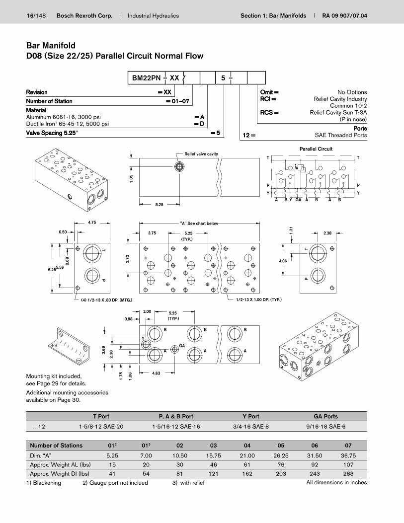
16/148 Bosch Rexroth Corp. Industrial Hydraulics Section 1: Bar Manifolds RA 09 907/07.04
RevisionRevisionRevisionRevisionRevision = XX= XX= XX= XX= XX
Number of StationNumber of StationNumber of StationNumber of StationNumber of Station = 01–07= 01–07= 01–07= 01–07= 01–07
MaterialMaterialMaterialMaterialMaterialAluminum 6061-T6, 3000 psi = A= A= A= A= ADuctile Iron1 65-45-12, 5000 psi = D= D= D= D= D
Valve Spacing 5.25Valve Spacing 5.25Valve Spacing 5.25Valve Spacing 5.25Valve Spacing 5.25″ = 5= 5= 5= 5= 5
Omit =Omit =Omit =Omit =Omit = No OptionsRCI =RCI =RCI =RCI =RCI = Relief Cavity Industry
Common 10-2RCS =RCS =RCS =RCS =RCS = Relief Cavity Sun T-3A
(P in nose)
PortsPortsPortsPortsPorts12 =12 =12 =12 =12 = SAE Threaded Ports
BM22PN – XX / 5 –
T Port P, A & B Port Y Port GA Ports
…12 1-5/8-12 SAE-20 1-5/16-12 SAE-16 3/4-16 SAE-8 9/16-18 SAE-6
Number of Stations 012 013 02 03 04 05 06 07
Dim. “A” 5.25 7.00 10.50 15.75 21.00 26.25 31.50 36.75
Approx. Weight AL (lbs) 15 20 30 46 61 76 92 107
Approx. Weight DI (lbs) 41 54 81 121 162 203 243 283
1) Blackening 2) Gauge port not inclued 3) with relief All dimensions in inches
Bar ManifoldD08 (Size 22/25) Parallel Circuit Normal Flow
(4) 1/2-13 X .80 DP. (MTG.) 1/2-13 X 1.00 DP. (TYP.)
(TYP.)
(TYP.)
Relief valve cavity
3.72
3.69
2.38
1.75
1.06
5.252.00
0.88
4.63
4.06
1.31
2.38
"A" See chart below
5.253.75
1.05
5.25
4.75
0.50
6.255.56
0.69
T
P
BAAGAYB
T
P
YYA
Parallel Circuit
B
A
B
A
B
A
B
GA
Y
PT
PT
Mounting kit included,see Page 29 for details.
Additional mounting accessoriesavailable on Page 30.

RA 09 907/07.04 Section 1: Bar Manifolds Industrial Hydraulics Bosch Rexroth Corp. 17/148
1/2-13 X .80 DP. (TYP.)
Threaded for1/16-27 NPTOptionalOrifice
1/2-13 X 1.00 DP. (TYP.)(4) 1/2-13 x .80 DP. (MTG.)
8.95
8.45
8.958.45
6.755.65
1.40
2.51
2.362.10
7.455.48
5.28
4.57
"A" (See Chart Below)5.00
(TYP.)
5.00 (TYP.)2.43
1.98
5.38
2.00
8.15
"B" (See Chart Below)
0.50
0.55
0.75
TX
YP
A BA B
XT
Y
A B
P
B
A
B
A
B
A
TYP
X
X
P
TY
Model Code P Port T Port A & B Ports X & Y Ports
BM22…07L 1-1/2” SAE 3000 psi 2” SAE 3000 psi 1-1/4” SAE 3000 psi SAE-12 (1-1/16-12)
BM22…07H 1-1/2” SAE 6000 psi 2” SAE 3000 psi 1-1/4” SAE 6000 psi SAE-12 (1-1/16-12)
BM22…12 SAE-24 (1-7/8-12) SAE-32 (2-1/2-12) SAE-20 (1-5/8-12) SAE-12 (1-1/16-12)
Parallel Circuit
Number of Stations 01 02 03 04 05 06
Dim. “A” 6.5 11.5 16.5 21.5 26.5 31.5Dim. “B” 2.5 7.5 12.5 17.5 22.5 27.5Approx. Weight DI (lbs) 136 240 344 448 552 656Approx. Weight AL (lbs) 51 90 129 168 208 247
1) Blackening
RevisionRevisionRevisionRevisionRevision = XX= XX= XX= XX= XX
Number of StationNumber of StationNumber of StationNumber of StationNumber of Station = 01–06= 01–06= 01–06= 01–06= 01–06
MaterialMaterialMaterialMaterialMaterialAluminum 6061-T6, 3000 psi = A= A= A= A= ADuctile Iron1 65-45-12, 5000 psi = D= D= D= D= D
Valve Spacing 5.0”Valve Spacing 5.0”Valve Spacing 5.0”Valve Spacing 5.0”Valve Spacing 5.0” = 5= 5= 5= 5= 5
Pressure RatingPressure RatingPressure RatingPressure RatingPressure RatingL =L =L =L =L = Low 3000 psi (Code 61)H =H =H =H =H = High 6000 psi (Code 62)
Available only on SAE Flanged Ports
PortsPortsPortsPortsPorts07 =07 =07 =07 =07 = SAE Flanged12 =12 =12 =12 =12 = SAE Threaded Ports
BM22PX – XX / 5 –
All dimensions in inches
Bar ManifoldD08 (Size 22/25) Parallel Circuit Extra High Flow
Mounting kit not included.

18/148 Bosch Rexroth Corp. Industrial Hydraulics Section 1: Bar Manifolds RA 09 907/07.04
GA
GA
GA
GB
GB
GB
TP
PT
AB
AB
AB
10-24 x 0.50 DP. (TYP.)
(4) 3/8-16 x 0.75 DP. (MTG.)
1.81
4.06
0.94
0.84
2.19 2.13(TYP.)
2.59
2.47
3.00
5.00
“A” (See Chart Below)
2.19
0.84
2.13(TYP.)
2.190.38
“B” (See Chart Below)
1.78
3.28
0.38
4.63
GB GAGB GAGAGB
T
P
B A B A B A
T
P
2.13(TYP.)
2.13(TYP.)
Parallel Circuit
Number of Stations 01 02 03 04 05 06 07 08
Dim. “A” 4.50 6.50 8.75 10.75 13.00 15.00 17.25 19.25
Dim. “B” 4.125 6.125 8.375 10.375 12.625 14.625 16.875 18.875
Approx. Weight DI (lbs) 18 25 34 42 51 59 67 75
1) Blackening
Mounting kit not included.
G =G =G =G =G = Gauge Ports for A and B
12 =12 =12 =12 =12 = SAE Threaded PortsP & T: 1 5/16-12 SAE-16A & B: 3/4-16 SAE-8GA: 7/16-20 SAE-4
RevisionRevisionRevisionRevisionRevision = XX= XX= XX= XX= XX
Number of StationNumber of StationNumber of StationNumber of StationNumber of Station = 01–08= 01–08= 01–08= 01–08= 01–08
MaterialMaterialMaterialMaterialMaterialDuctile Iron1 65-45-12, 5000 psi = D= D= D= D= D
Valve Spacing 2.125”Valve Spacing 2.125”Valve Spacing 2.125”Valve Spacing 2.125”Valve Spacing 2.125” = 2= 2= 2= 2= 2
ABM6PL – XX / D 2 – G
All dimensions in inches
Bar ManifoldD03 (Size 6) Parallel Circuit Low Flow

RA 09 907/07.04 Section 1: Bar Manifolds Industrial Hydraulics Bosch Rexroth Corp. 19/148
Parallel Circuit
GB
GB
2.13(TYP.)
GB
2.19
0.84
2.59
2.47
“A” (See Chart Below)
GA
BA
GA
2.19
GA
BA
0.382.19
0.38
1.78
BA4.63
3.28
See Chart Below
“B” (See Chart Below)
See Chart Below
3.00
TP5.00
4.06T
0.94
1.81
P
GB GAGB GAGAGB
T
P
B A B A B A
T
P2.13(TYP.)
2.13(TYP.)
0.84
2.13(TYP.)
Number of Stations 01 02 03 04 05 06 07 08
Dim. “A” 4.50 6.50 8.75 10.75 13.00 15.00 17.25 19.25
Dim. “B” 4.125 6.125 8.375 10.375 12.625 14.625 16.875 18.875
Approx. Weight DI (lbs) 18 25 34 42 51 59 67 75
Approx. Weidht AL (lbs) 7 9 13 16 19 22 25 28
1) Blackening
Mounting kit not included.
P & T Ports A & B Ports GA & GB Ports Manifold (Mtg.) Valve (Mtg.)
…12G 1-5/16-12 SAE-16 7/8-14 SAE-10 7/16-20 SAE-4 3/8-16 x 0.75 DP. 10-24 x 0.50 DP.
…01GM 1” BSPP 1/2” BSPP 1/4” BSPP M10 x 0.75 DP. M5 x 0.50 DP.
RevisionRevisionRevisionRevisionRevision = XX= XX= XX= XX= XX
Number of StationNumber of StationNumber of StationNumber of StationNumber of Station = 01–08= 01–08= 01–08= 01–08= 01–08
MaterialMaterialMaterialMaterialMaterialAluminum 6061-T6, 3000 psi = A= A= A= A= ADuctile Iron1 65-45-12, 5000 psi = D= D= D= D= D
Valve Spacing 2.125”Valve Spacing 2.125”Valve Spacing 2.125”Valve Spacing 2.125”Valve Spacing 2.125” = 2= 2= 2= 2= 2
Omit =Omit =Omit =Omit =Omit = UNC Mounting TapsM =M =M =M =M = Metric Mounting Taps
BSPP Ports only
G =G =G =G =G = Gauge Ports for A and B
12 =12 =12 =12 =12 = SAE Threaded Ports01 =01 =01 =01 =01 = BSPP Threaded Ports
ABM6PN – XX / 2 – G
All dimensions in inches
Bar ManifoldD03 (Size 6) Parallel Circuit Normal Flow

20/148 Bosch Rexroth Corp. Industrial Hydraulics Section 1: Bar Manifolds RA 09 907/07.04
Number of Stations 01 02 03 04 05 06 07 08
Dim. “A” 4.50 6.50 8.75 10.75 13.00 15.00 17.25 19.25
Dim. “B” 4.125 6.125 8.375 10.375 12.625 14.625 16.875 18.875
Approx. Weight DI (lbs) 18 25 34 42 51 59 67 75
Ports conform to ISO 6149-1: 1993, Connections for Fluid Power and General Use – Ports and Stud Ends with ISO 261 Threads andO-Ring Sealing – Part 1: Ports with O-Ring Seal in Truncated Housing1) Blackening
Mounting kit not included.
M =M =M =M =M = Metric Mounting TapsISO 6149-1 Ports only
G =G =G =G =G = Gauge Ports for A and B
50 =50 =50 =50 =50 = ISO 6149-1P & T: M33 x 2A & B: M22 x 1.5GA: M12 x 1.5
RevisionRevisionRevisionRevisionRevision = XX= XX= XX= XX= XX
Number of StationNumber of StationNumber of StationNumber of StationNumber of Station = 01–08= 01–08= 01–08= 01–08= 01–08
MaterialMaterialMaterialMaterialMaterialDuctile Iron1 65-45-12, 5000 psi = D= D= D= D= D
Valve Spacing 2.125”Valve Spacing 2.125”Valve Spacing 2.125”Valve Spacing 2.125”Valve Spacing 2.125” = 2= 2= 2= 2= 2
ABM6PH – XX / D 2 – 50 G M
All dimensions in inches
Bar ManifoldD03 (Size 6) Parallel Circuit High Flow with ISO 6149-1
0.94
4.06
0.84
1.81
2.19
2.59
2.13(TYP.)
2.47
“A” (See Chart Below)
M5 x 12mm DP. (TYP.)
5.00
3.00
GB
GB
GB
TP
0.84
0.382.19
3.28
4.63
1.78
0.38
“B” (See Chart Below)
(4) M10 x 19mm DP. (MTG.)
GA
GA
GA
2.19
TP
ABB
AAB
GB GAGB GAGAGB
T
P
B A B A B A
T
P
2.13(TYP.)
2.13(TYP.)
2.13(TYP.)
Parallel Cirucit

RA 09 907/07.04 Section 1: Bar Manifolds Industrial Hydraulics Bosch Rexroth Corp. 21/148
Number of Stations 01 02 03 04 05 06 07 08
Dim. “A” 6.25 8.25 10.50 12.50 14.75 16.75 19.00 21.00
Dim. “B” 5.865 7.875 10.125 12.125 14.375 16.375 18.625 20.625
Approx. Weight DI (lbs) 25 32 41 49 58 66 74 82
1) Blackening
Parallel Circuit
0.94
4.06
1.814.59
4.19
“A” (See Chart Below)
2.13(TYP.)
1.884.19
4.19
“B” (See Chart Below)
0.84
2.47
3.00
5.00
0.84
0.94
3.284.06
4.63
1.78
0.38
See Chart Below
0.38
See Chart Below
2.13(TYP.)
2.13(TYP.)
2.13(TYP.)
PT
T
P
TT
P
B A GAGAABGB GBB AGB
P
GA
TP A
BBAA
B
GB
GB
GB
GA
GA
GA
TP
Mounting kit not included.
RevisionRevisionRevisionRevisionRevision = XX= XX= XX= XX= XX
Number of StationNumber of StationNumber of StationNumber of StationNumber of Station = 01–08= 01–08= 01–08= 01–08= 01–08
MaterialMaterialMaterialMaterialMaterialDuctile Iron1 65-45-12, 5000 psi = D= D= D= D= D
Valve Spacing 2.125”Valve Spacing 2.125”Valve Spacing 2.125”Valve Spacing 2.125”Valve Spacing 2.125” = 2= 2= 2= 2= 2
SAE Threaded Ports = 12= 12= 12= 12= 12BSPP Threaded Ports = 01= 01= 01= 01= 01
ABM6PN – XX / D 2 – G B
Omit =Omit =Omit =Omit =Omit = UNC Mounting TapsM =M =M =M =M = Metric Mounting Taps
BSPP Ports only
B =B =B =B =B = Bottom Ported P and T
G =G =G =G =G = Gauge Ports for A and B
All dimensions in inches
Bar ManifoldD03 (Size 6) Parallel Circuit Normal Flow with Bottom-Ported P & T
P & T Ports A & B Ports GA & GB Ports Manifold (Mtg.) Valve (Mtg.)
…12G 1-5/16-12 SAE-16 7/8-14 SAE-10 7/16-20 SAE-4 3/8-16 x 0.75 DP. 10-24 x 0.50 DP.
…01GM 1” BSPP 1/2” BSPP 1/4” BSPP M10 x 0.75 DP. M5 x 0.50 DP.

22/148 Bosch Rexroth Corp. Industrial Hydraulics Section 1: Bar Manifolds RA 09 907/07.04
Parallel Circuit
GB
GB
GB
GA
GA
GA
BAA
B
AB
PTT
P
“A” (See Chart Below)
Not Available On 1 StationThru Holes For 3/8" SHCS (Mtg.)
1/4-20 x 0.60 DP. (TYP.)
(4) 3/8-16 x 0.75 DP. (MTG.)
5.50
3.001.16
4.56
2.19
2.06
3.75 (TYP.)1.94
1.12
“D,E*” (See Chart Below)
1.34
3.63
2.63
0.50
3.88
3.75 (TYP.)
3.75 (TYP.)
3.75 (TYP.)
“B,C*” (See Chart Below)
1.94
1.12
1.940.38
2.03
0.385.13
4.44
GBGAGBGAGA GB
T
P
BABA B A
T
P
Number of Stations 01 02 03 04 05 06 07 08
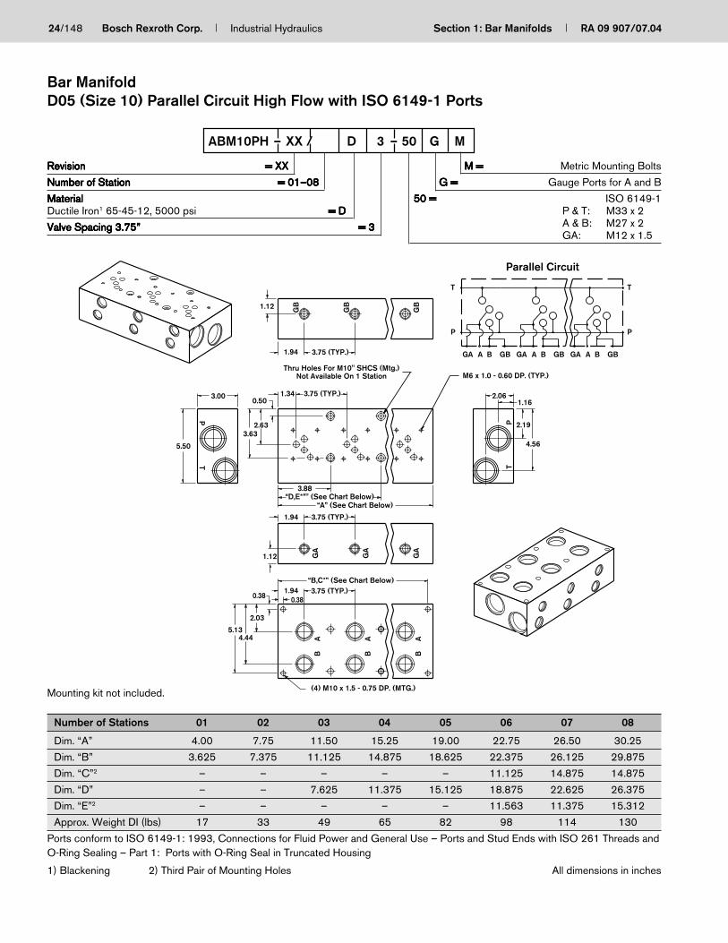
Dim. “A” 4.00 7.75 11.50 15.25 19.00 22.75 26.50 30.25
Dim. “B” 3.625 7.375 11.125 14.875 18.625 22.375 26.125 29.875
Dim. “C”2 – – – – – 11.125 14.875 14.875
Dim. “D” – – 7.625 11.375 15.125 18.875 22.625 26.375
Dim. “E”2 – – – – – 11.563 11.375 15.312
Approx. Weight DI (lbs) 17 33 49 65 82 98 114 130
1) Blackening 2) Third Pair of Mounting Holes
Mounting kit not included.
RevisionRevisionRevisionRevisionRevision = XX= XX= XX= XX= XX
Number of StationNumber of StationNumber of StationNumber of StationNumber of Station = 01–08= 01–08= 01–08= 01–08= 01–08
MaterialMaterialMaterialMaterialMaterialDuctile Iron1 65-45-12, 5000 psi = D= D= D= D= D
Valve Spacing 3.75”Valve Spacing 3.75”Valve Spacing 3.75”Valve Spacing 3.75”Valve Spacing 3.75” = 3= 3= 3= 3= 3
G =G =G =G =G = Gauge Ports for A and B
12 =12 =12 =12 =12 = SAE Threaded PortsP & T: 1 5/16-12 SAE-16A & B: 7/8-14 SAE-10GA: 7/16-20 SAE-4
ABM10PL – XX/ D 3 – 12 G
All dimensions in inches
Bar ManifoldD05 (Size 10) Parallel Circuit Low Flow

RA 09 907/07.04 Section 1: Bar Manifolds Industrial Hydraulics Bosch Rexroth Corp. 23/148
P & T Ports A & B Ports GA & GB Ports Manifold (Mtg.) Valve (Mtg.) Thru (Mtg.)
…12G 1-5/16-12 SAE-16 1-1/16-12 SAE-12 7/16-20 SAE-4 3/8-16 x 0.75 DP. 1/4-20 x 0.60 DP. 3/8” SHCS
…01GM 1” BSPP 3/4” BSPP 1/4” BSPP M10 x 0.60 DP. M6 x 0.60 DP. M10” SHCS
See Chart Below
4.56
2.19
2.061.16
See Chart Below
PT
3.00
5.50
PT
GB
GB
See Chart Below
GB1.12
0.50
2.63
3.63
1.34
1.94 3.75(TYP.)
GA
GA
BA
BA
3.88
0.38
GA
1.12
1.94
1.94
BA
0.38
2.03
4.445.13
“B,C*” (See Chart Below)3.75 (TYP.)
3.75 (TYP.)
“D,E*” (See Chart Below)“A” (See Chart Below)
GBGAGBGAGA GB
T
P
BABA B A
T
P
3.75(TYP.)
Parallel Circuit
Mounting kit not included.
Number of Stations 01 02 03 04 05 06 07 08
Dim. “A” 4.00 7.75 11.50 15.25 19.00 22.75 26.50 30.25Dim. “B” 3.625 7.375 11.125 14.875 18.625 22.375 26.125 29.875Dim. “C”2 – – – – – 11.125 14.875 14.875Dim. “D” – – 7.625 11.375 15.125 18.875 22.625 26.375Dim. “E”2 – – – – – 11.563 11.375 15.312Approx. Weight DI (lbs) 17 33 49 65 82 98 114 130Approx. Weight AL (lbs) 6 12 18 24 31 37 43 49
1) Blackening 2) Third Pair of Mounting Holes
RevisionRevisionRevisionRevisionRevision = XX= XX= XX= XX= XX
Number of StationNumber of StationNumber of StationNumber of StationNumber of Station = 01–08= 01–08= 01–08= 01–08= 01–08
MaterialMaterialMaterialMaterialMaterialAluminum 6061-T6, 3000 psi = A= A= A= A= ADuctile Iron1 65-45-12, 5000 psi = D= D= D= D= D
Valve Spacing 3.75”Valve Spacing 3.75”Valve Spacing 3.75”Valve Spacing 3.75”Valve Spacing 3.75” = 3= 3= 3= 3= 3
Omit =Omit =Omit =Omit =Omit = UNC Mounting TapsM =M =M =M =M = Metric Mounting Taps
BSPP Ports only
G =G =G =G =G = Gauge Ports for A and B
12 =12 =12 =12 =12 = SAE Threaded Ports01 =01 =01 =01 =01 = BSPP Threaded Ports
ABM10PN – XX / 3 – G
All dimensions in inches
Bar ManifoldD05 (Size 10) Parallel Circuit Normal Flow
24/148 Bosch Rexroth Corp. Industrial Hydraulics Section 1: Bar Manifolds RA 09 907/07.04
Parallel Circuit
1.16
4.56
P 2.19
2.06
M6 x 1.0 - 0.60 DP. (TYP.)
T
3.00
5.50
PT
Not Available On 1 StationThru Holes For M10" SHCS (Mtg.)
GB
3.75 (TYP.)
GB
1.94
1.12
3.75 (TYP.)1.34
3.632.63
0.50
GB
GA
3.75 (TYP.)
“A” (See Chart Below)
1.94
“D,E*”" (See Chart Below)3.88
GA
GA
3.75 (TYP.)“B,C*” (See Chart Below)
1.12
0.381.94
BA
BB
AA
0.38
2.03
4.445.13
(4) M10 x 1.5 - 0.75 DP. (MTG.)
GBGAGBGAGA GB
T
P
BABA B A
T
P
Number of Stations 01 02 03 04 05 06 07 08
Dim. “A” 4.00 7.75 11.50 15.25 19.00 22.75 26.50 30.25
Dim. “B” 3.625 7.375 11.125 14.875 18.625 22.375 26.125 29.875
Dim. “C”2 – – – – – 11.125 14.875 14.875
Dim. “D” – – 7.625 11.375 15.125 18.875 22.625 26.375
Dim. “E”2 – – – – – 11.563 11.375 15.312
Approx. Weight DI (lbs) 17 33 49 65 82 98 114 130
Ports conform to ISO 6149-1: 1993, Connections for Fluid Power and General Use – Ports and Stud Ends with ISO 261 Threads andO-Ring Sealing – Part 1: Ports with O-Ring Seal in Truncated Housing
1) Blackening 2) Third Pair of Mounting Holes
Mounting kit not included.
M =M =M =M =M = Metric Mounting Bolts
G =G =G =G =G = Gauge Ports for A and B
50 =50 =50 =50 =50 = ISO 6149-1P & T: M33 x 2A & B: M27 x 2GA: M12 x 1.5
RevisionRevisionRevisionRevisionRevision = XX= XX= XX= XX= XX
Number of StationNumber of StationNumber of StationNumber of StationNumber of Station = 01–08= 01–08= 01–08= 01–08= 01–08
MaterialMaterialMaterialMaterialMaterialDuctile Iron1 65-45-12, 5000 psi = D= D= D= D= D
Valve Spacing 3.75”Valve Spacing 3.75”Valve Spacing 3.75”Valve Spacing 3.75”Valve Spacing 3.75” = 3= 3= 3= 3= 3
ABM10PH – XX / D 3 – 50 G M
All dimensions in inches
Bar ManifoldD05 (Size 10) Parallel Circuit High Flow with ISO 6149-1 Ports
RA 09 907/07.04 Section 1: Bar Manifolds Industrial Hydraulics Bosch Rexroth Corp. 25/148
See Chart Below
See Chart Below
Not Available On 1 StationSee Chart Below
T
P
T
P
A B GBA BGA GBBA GBGA GA
T
P
3.310.92
1.162.06
3.75 (TYP.)4.24
“D,E*” (see Chart Below)
6.13
1.12
3.753.64
1.882.88
5.00
3.75 (TYP.)4.24
“A” (See Chart Below)
3.75 (TYP.)4.240.38
3.312.03
0.94
0.382.00
“B,C” (See Chart Below)
1.12
3.00
5.50
4.445.13
Parallel Circuit
GA
GA
GA
TP
TP A
B
ABB
A
GB
GB
GB
TP
Mounting kit not included.
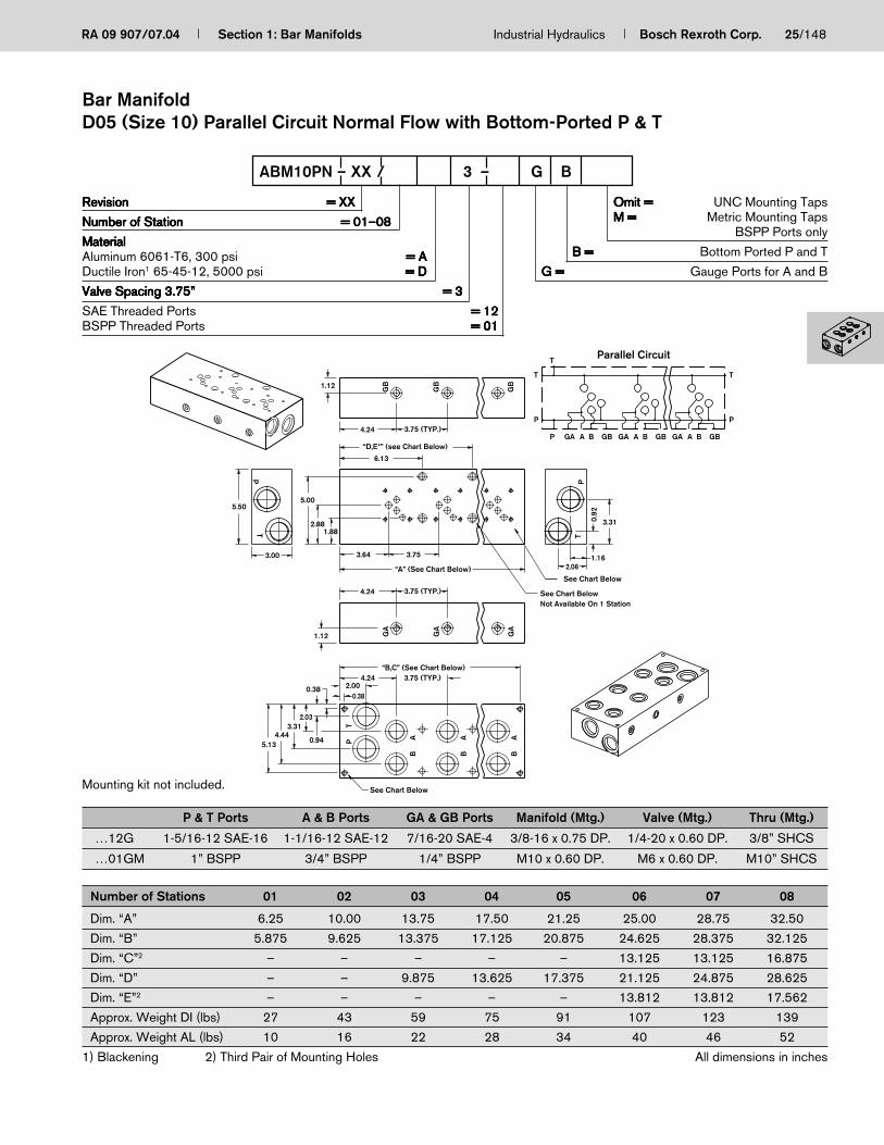
Number of Stations 01 02 03 04 05 06 07 08
Dim. “A” 6.25 10.00 13.75 17.50 21.25 25.00 28.75 32.50
Dim. “B” 5.875 9.625 13.375 17.125 20.875 24.625 28.375 32.125
Dim. “C”2 – – – – – 13.125 13.125 16.875
Dim. “D” – – 9.875 13.625 17.375 21.125 24.875 28.625
Dim. “E”2 – – – – – 13.812 13.812 17.562
Approx. Weight DI (lbs) 27 43 59 75 91 107 123 139
Approx. Weight AL (lbs) 10 16 22 28 34 40 46 52
1) Blackening 2) Third Pair of Mounting Holes All dimensions in inches
Bar ManifoldD05 (Size 10) Parallel Circuit Normal Flow with Bottom-Ported P & T
RevisionRevisionRevisionRevisionRevision = XX= XX= XX= XX= XX
Number of StationNumber of StationNumber of StationNumber of StationNumber of Station = 01–08= 01–08= 01–08= 01–08= 01–08
MaterialMaterialMaterialMaterialMaterialAluminum 6061-T6, 300 psi = A= A= A= A= ADuctile Iron1 65-45-12, 5000 psi = D= D= D= D= D
Valve Spacing 3.75”Valve Spacing 3.75”Valve Spacing 3.75”Valve Spacing 3.75”Valve Spacing 3.75” = 3= 3= 3= 3= 3
SAE Threaded Ports = 12= 12= 12= 12= 12BSPP Threaded Ports = 01= 01= 01= 01= 01
ABM10PN – XX / 3 – G B
Omit =Omit =Omit =Omit =Omit = UNC Mounting TapsM =M =M =M =M = Metric Mounting Taps
BSPP Ports only
B =B =B =B =B = Bottom Ported P and T
G =G =G =G =G = Gauge Ports for A and B
P & T Ports A & B Ports GA & GB Ports Manifold (Mtg.) Valve (Mtg.) Thru (Mtg.)
…12G 1-5/16-12 SAE-16 1-1/16-12 SAE-12 7/16-20 SAE-4 3/8-16 x 0.75 DP. 1/4-20 x 0.60 DP. 3/8” SHCS
…01GM 1” BSPP 3/4” BSPP 1/4” BSPP M10 x 0.60 DP. M6 x 0.60 DP. M10” SHCS

26/148 Bosch Rexroth Corp. Industrial Hydraulics Section 1: Bar Manifolds RA 09 907/07.04
Number of Stations 01 02 03 04 05 06 07 08
Dim. “A” 6.50 12.50 18.50 24.5 30.5 36.5 42.5 48.5
Approx. Weight DI (lbs) 54 104 153 203 253 303 353 403
1) Blackening
6.00 (TYP.)
TP
DR
DR
PT
GA
GA
GA
BA
BA
BA
GB
GB
GB
See Chart Below
See Chart Below
0.75
1.50
6.00 (TYP.)
“A” (See Chart Below)6.00 (TYP.)
3.00
1.25
0.90
4.00
6.69
6.00 (TYP.)
6.00 (TYP.)
3.38
3.50
3.38
8.00
5.50
3.00
0.50
6.257.50
3.00 6.00 (TYP.)
3.254.10
A GAGB BAB GAGBGB B GA
DRDR
T
P
A
T
P
Parallel Circuit
P & T Ports A & B Ports GA & GB Ports DR Ports Manifold (Mtg.) Valve (Mtg.)
…12G 1-7/8-12 SAE-24 1 5/8-12 SAE-20 7/16-20 SAE-4 9/16-18 SAE-6 1/2-13 x 0.80 DP. 1/2-13 x 1.00 DP.
…01GM 1-1/2” BSPP 1-1/4” BSPP 1/4” BSPP 1/4” BSPP M12 x 0.80 DP. M12 x 0.80 DP.
…05G 1-1/2” NPT 1-1/4” NPT 1/4” NPT 1/4” NPT 1/2-13 x 0.80 DP. 1/2-13 x 1.00 DP.
…50GM M48 M42 M10 M10 M12 x 0.80 DP. M12 x 0.80 DP.
Mounting kit not included.
RevisionRevisionRevisionRevisionRevision = XX= XX= XX= XX= XX
Number of StationNumber of StationNumber of StationNumber of StationNumber of Station = 01–08= 01–08= 01–08= 01–08= 01–08
MaterialMaterialMaterialMaterialMaterialDuctile Iron1 65-45-12, 5000 psi = D= D= D= D= D
Valve Spacing 6.0”Valve Spacing 6.0”Valve Spacing 6.0”Valve Spacing 6.0”Valve Spacing 6.0” = 6= 6= 6= 6= 6
Omit =Omit =Omit =Omit =Omit = UNC Mounting TapsSAE Mounting
M =M =M =M =M = Metric Mounting TapsMetric and BSPP Ports only
G =G =G =G =G = Gauge Ports for A and B
12 =12 =12 =12 =12 = SAE Threaded Ports05 =05 =05 =05 =05 = NPT Threaded Ports01 =01 =01 =01 =01 = BSPP Threaded Ports50 =50 =50 =50 =50 = Metric Threaded Ports
ABM22PN – XX / D 6 – G
All dimensions in inches
Bar ManifoldD08 (Size 22/25) Parallel Circuit Normal Flow

RA 09 907/07.04 Section 1: Bar Manifolds Industrial Hydraulics Bosch Rexroth Corp. 27/148
Number of Stations 012 02 03 04 05 06 07 08
Dim. “A” 2.13 4.25 6.38 8.50 10.63 12.75 14.88 17.00
Approx. Weight DI (lbs) 5 10 15 20 25 30 35 40
Ports conform to ISO 6149-1: 1993, Connections for Fluid Power and General Use – Ports and Stud Ends with ISO 261 Threads andO-Ring Sealing
1) Blackening 2) Gauge port not included
GA
T
P
B A B A B A
T
P
M5 x 0.8 - 0.50 DP. (TYP.)
3.00
(2) M8 x .45 DP.
TP
TP
GA
A
B
A
B
A
B
2.381.50
0.63
2.13
2.13 TYP1.06
2.24
0.76
1.50
1.842.69
0.31
3.00
0.31
"A" (See Chart Below)
2.13 TYP0.66
Parallel Circuit
RevisionRevisionRevisionRevisionRevision = XX= XX= XX= XX= XX
Number of StationNumber of StationNumber of StationNumber of StationNumber of Station = 01–08= 01–08= 01–08= 01–08= 01–08
MaterialMaterialMaterialMaterialMaterialDuctile Iron1 65-45-12, 5000 psi = D= D= D= D= D
Valve Spacing 2.125”Valve Spacing 2.125”Valve Spacing 2.125”Valve Spacing 2.125”Valve Spacing 2.125” = 2= 2= 2= 2= 2
M =M =M =M =M = Metric Mounting Taps
50 =50 =50 =50 =50 = Metric Threaded PortsP & T: M22 x 1.5A & B: M18 x 1.5GA: M12 x 1.5
IBM6PN – XX / D 2 – 50 M
All dimensions in inches
ISO Bar ManifoldD03 (Size 6) Parallel Circuit Normal Flow
Mounting kit included,see Page 29 for details.
Additional mounting accessoriesavailable on Page 30.

28/148 Bosch Rexroth Corp. Industrial Hydraulics Section 1: Bar Manifolds RA 09 907/07.04
Number of Stations 012 02 03 04 05 06 07 08
Dim. “A” 3.25 6.50 9.75 13.00 16.25 19.50 22.75 26.00
Approx. Weight DI (lbs) 10 21 31 41 52 62 72 83
Ports conform to ISO 6149-1: 1993, Connections for Fluid Power and General Use – Ports and Stud Ends with ISO 261 Threads andO-Ring Sealing
1) Blackening 2) Gauge port not included
P
A BBAGA
T
BA
P
T
M6 x 1.0 - 0.60 DP. (TYP.)(2) M8 x .60 DP.
PT
B
A A
B
A
B
GA
TP
3.502.94
0.56
3.500.31
2.81
1.75
0.69
3.19
3.25 TYP1.56
2.19
"A" (See Chart Below)3.25 TYP2.28 1.75
2.62
0.88
Parallel Circuit
RevisionRevisionRevisionRevisionRevision = XX= XX= XX= XX= XX
Number of StationNumber of StationNumber of StationNumber of StationNumber of Station = 01–08= 01–08= 01–08= 01–08= 01–08
MaterialMaterialMaterialMaterialMaterialDuctile Iron1 65-45-12, 5000 psi = D= D= D= D= D
Valve Spacing 3.25”Valve Spacing 3.25”Valve Spacing 3.25”Valve Spacing 3.25”Valve Spacing 3.25” = 3= 3= 3= 3= 3
M =M =M =M =M = Metric Mounting Taps
50 =50 =50 =50 =50 = Metric Threaded PortsP & T: M27 x 2A & B: M18 x 1.5GA: M12 x 1.5
IBM10PN – XX / D 3 – 50 M
All dimensions in inches
ISO Bar ManifoldD05 (Size 10) Parallel Circuit Normal Flow
Mounting kit included,see Page 29 for details.
Additional mounting accessoriesavailable on Page 30.

RA 09 907/07.04 Section 1: Bar Manifolds Industrial Hydraulics Bosch Rexroth Corp. 29/148
Size Flow Port StyleMounting
A B C D E FGauge Port Mtg. Screws (8)
BracketKit (1) Plug Hex HD Washer Bolt
...12 SAE R978839831 –6 SAE UNC 5/16-18 x 0.50
Normal...05 NPT R978917127
3.00 1.00 1.00 2.38 0.31 0.281/4” NPT UNC 5/16-18 x 0.50
D03...01 BSPP R978915774 1/4” BSPP M8 x 12...50 Metric R978902527 M12 x 1.5 M8 x 12
High...12 SAE R978906094
4.00 1.00 1.00 3.38 0.31 0.28–6 SAE UNC 5/16-18 x 0.50
...01 BSPP R978910319 1/4” BSPP M8 x 12
...12 SAE R978839832 –6 SAE UNC 5/16-18 x 0.50
Normal...05 NPT R978917413
3.00 1.00 1.00 2.38 0.31 0.281/4” NPT UNC 5/16-18 x 0.50 (2)
D05...01 BSPP R978915775 1/4” BSPP M8 x 12 Bracket,...50 Metric R978902528 M12 x 1.5 M8 x 12 CS Yellow
High...12 SAE R978906095
5.00 1.38 1.38 4.13 0.44 0.28–6 SAE UNC 3/8-16 x 0.75 Chromate
...01 BSPP R978910315 1/4” BSPP M10 x 16 Plate
Normal...12 SAE R978915619
5.00 1.38 1.38 4.13 0.44 0.28–6 SAE UNC 3/8-16 x 0.75
D07...01 BSPP R978915620 1/4” BSPP M10 x 16
High...12 SAE R978915621
6.00 1.63 1.63 4.88 0.56 0.56–6 SAE UNC 3/8-16 x 0.75
...01 BSPP R978915622 1/4” BSPP M10 x 16
D08 Normal...12 SAE R978915500
6.00 1.63 1.63 4.88 0.56 0.56–6 SAE UNC 1/2-13 x 0.75
...01 BSPP R978915623 1/4” BSPP M12 x 16
Manifold Mounting Hardware Accessories(Included with BM assemblies)
30/148 Bosch Rexroth Corp. Industrial Hydraulics Section 1: Bar Manifolds RA 09 907/07.04
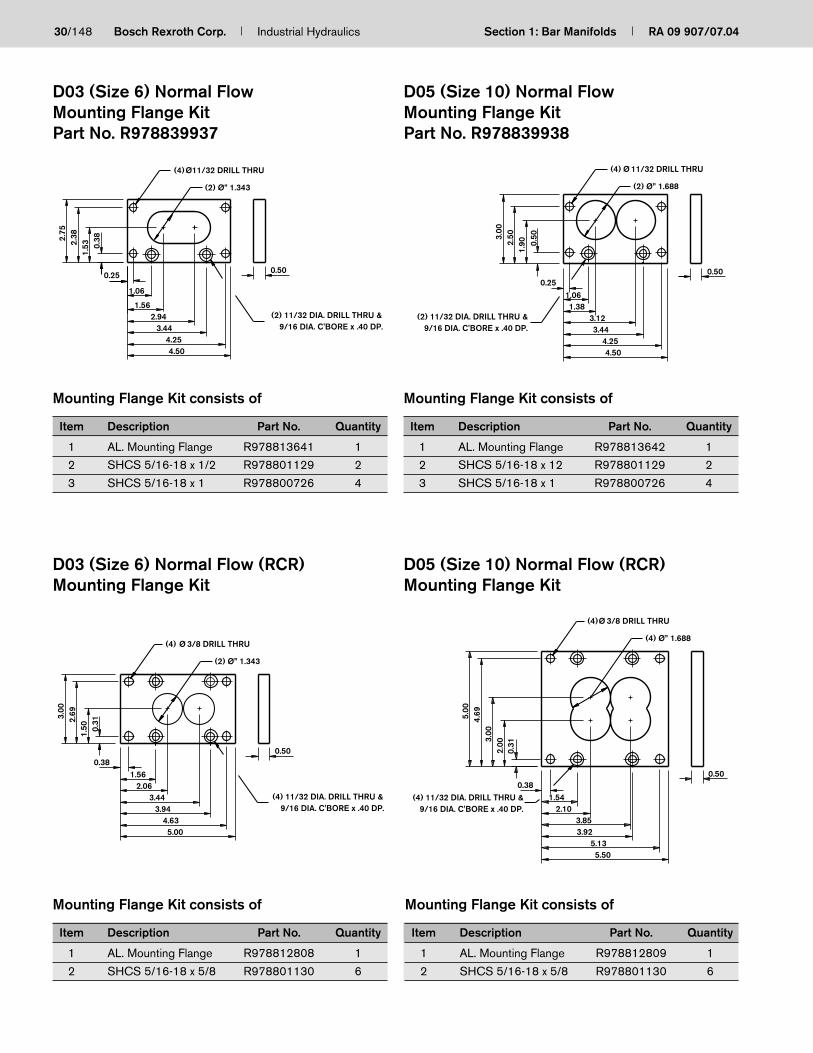
D03 (Size 6) Normal FlowMounting Flange KitPart No. R978839937
Mounting Flange Kit consists of
Item Description Part No. Quantity
1 AL. Mounting Flange R978813641 1
2 SHCS 5/16-18 x 1/2 R978801129 2
3 SHCS 5/16-18 x 1 R978800726 4
Mounting Flange Kit consists of
Item Description Part No. Quantity
1 AL. Mounting Flange R978813642 1
2 SHCS 5/16-18 x 12 R978801129 2
3 SHCS 5/16-18 x 1 R978800726 4
D05 (Size 10) Normal FlowMounting Flange KitPart No. R978839938
D03 (Size 6) Normal Flow (RCR)Mounting Flange Kit
D05 (Size 10) Normal Flow (RCR)Mounting Flange Kit
Mounting Flange Kit consists of
Item Description Part No. Quantity
1 AL. Mounting Flange R978812808 1
2 SHCS 5/16-18 x 5/8 R978801130 6
Mounting Flange Kit consists of
Item Description Part No. Quantity
1 AL. Mounting Flange R978812809 1
2 SHCS 5/16-18 x 5/8 R978801130 6
9/16 DIA. C'BORE x .40 DP.(2) 11/32 DIA. DRILL THRU &
0.50
Ø(4)
0.25
1.06
1.56
1.532.
382.75
0.38
4.253.44
4.50
2.94
11/32 DRILL THRU
(2) Ø” 1.343
Ø(4) 11/32 DRILL THRU
(2) Ø” 1.688
0.50
0.50
0.251.061.38
1.90
3.00
2.50
3.444.254.50
3.129/16 DIA. C'BORE x .40 DP.
(2) 11/32 DIA. DRILL THRU &
9/16 DIA. C'BORE x .40 DP.(4) 11/32 DIA. DRILL THRU &
(4) Ø 3/8 DRILL THRU
(2) Ø” 1.343
0.50
1.50 0.
31
3.00
2.69
0.38
2.061.56
3.944.635.00
3.44
0.50
Ø(4)
2.10
0.31
2.003.
00
0.381.54
4.695.00
3/8 DRILL THRU
(4) Ø” 1.688
5.133.92
5.50
3.859/16 DIA. C'BORE x .40 DP.
(4) 11/32 DIA. DRILL THRU &

The Drive & Control Company
ServiceAutomation
MobileHydraulics
IndustrialHydraulics
Electric Drivesand Controls
Linear Motion andAssembly Technologies Pneumatics
Section 2Subplates
RA 09 907/07.04
31
Subplate Features
– Sizes 6 to 22
– Aluminum and ductile iron
– Side or bottom ported
– SAE, BSPP, or NPT porting
– Includes mounting kit for the subplate

32/148 Bosch Rexroth Corp. Industrial Hydraulics Section 2: Subplates RA 09 907/07.04
Section 2 Index
Description Page
Subplate D03 (Size 6) Bottom Ported ............................................................................................................................................................................. 33
Subplate D05 (Size 10) Bottom Ported .......................................................................................................................................................................... 34
Subplate D07 (Size 16) Bottom Ported .......................................................................................................................................................................... 35
Subplate D08 (Size 22/25) Bottom Ported .................................................................................................................................................................... 36
Subplate D10 (Size 32) Bottom Ported .......................................................................................................................................................................... 37
Subplate D03 (Size 6) Side Ported .................................................................................................................................................................................. 38
Subplate D05 (Size 10) Side Ported ............................................................................................................................................................................... 39
Subplate D07 (Size 16) Side Ported ............................................................................................................................................................................... 40
Subplate D08 (Size 22) Side Ported ............................................................................................................................................................................... 41

RA 09 907/07.04 Section 2: Subplates Industrial Hydraulics Bosch Rexroth Corp. 33/148
P,T & A,B Ports Mounting Bolts Valve Mtg.Port type 12 05 01 12 05 01 05&12 01
SP6BN-1X/… 9/16-18 NPT 1/4” G (BSP) 1/4” 1/4-20 x 0.75 LG 1/4-20 x 0.75 LG M6-1.0 x (20) LGSAE-6 SHCS SHCS SHCS
SP6BH-1X/… 3/4-16 NPT 3/8” G (BSP) 3/8” 1/4-20 x 0.75 LG 1/4-20 x 0.75 LG M6-1.0 x (20) LG 10-24 M5-0.8SAE-8 SHCS SHCS SHCS x 0.50 DP x (12.7) DP
SP6BX-1X/… 7/8-14 NPT 1/2” G (BSP) 1/2” 1/4-20 x 0.75 LG 1/4-20 x 0.75 LG M6-1.0 x (20) LGSAE-10 SHCS SHCS SHCS
SP6BNH-1X/... — NPT 1/4” — — 1/4-20 x 0.75 LG — 1/4-20 —x 0.50 DP
Dimension A B C D E F G H I J K L M N
SP6BN… 3.75 2.50 1.00 3.46 1.88 0.31 1.25 1.66 2.59 1.88 1.17 1.92 1.25 0.58
SP6BH… 4.00 3.00 1.19 3.77 2.00 0.22 1.50 1.91 2.94 2.00 1.05 2.17 1.50 0.83
SP6BX… 5.00 4.00 1.38 4.67 2.50 0.34 2.00 2.41 3.58 2.50 1.42 3.14 2.00 0.86
Mounting hardware is supplied. Valve mounting hardware must be ordered separately.
1) Blackening
FlowFlowFlowFlowFlowNormal = N= N= N= N= NHigh = H= H= H= H= HExtra High = X= X= X= X= X
High Pressure = H= H= H= H= H
RevisionRevisionRevisionRevisionRevision = XX= XX= XX= XX= XX
PortsPortsPortsPortsPorts12 =12 =12 =12 =12 = SAE Threaded Ports05 =05 =05 =05 =05 = NPT Threaded Ports01 =01 =01 =01 =01 = BSPP Threaded Ports
MaterialMaterialMaterialMaterialMaterialA =A =A =A =A = Aluminum 6061–T6, 3000 psiD =D =D =D =D = Ductile Iron1 65-45-12, 5000 psi
SP6B – XX / –
H
A
D
B
G
EF C
B
T
P
PBT
A
A
I
J
K
L
M
N
See Chart
All dimensions in inches
Approx. WeightPort type Alum Duct
SP6BN-1X/… 0.9 2.4SP6BH-1X/… 1.4 3.7SP6BX-1X/… 2.7 7.2SP6BNH-1X/... — 2.4
SubplatesD03 (Size 6) Bottom-Ported

34/148 Bosch Rexroth Corp. Industrial Hydraulics Section 2: Subplates RA 09 907/07.04
Appox. Wt.Model Alum. Iron Steel
SP10BL... 2.2 5.8 —
SP10BN... 2.5 6.6 —
SP10BH... 4.7 12.5 —
SP10BX... 4.7 12.5 —
SP10BNH... — — 6.4
P,T & A,B Ports X & Y Ports Mounting Bolts Valve Mtg.Port type 12 05 01 12 05 01 12 05 01 05 & 12 01
SP10BL… 9/16-18 NPT 3/8” G (BSP) 3/8” — — — 3/8-16 x 1.50 LG 3/8-16 x 1.50 LG M10-1.5 x (40) LGSAE-6 SHCS SHCS SHCS
SP10BN… 3/4-16 NPT 1/2” G (BSP) 1/2” — — — 3/8-16 x 1.50 LG 3/8-16 x 1.50 LG M10-1.5 x (40) LGSAE-8 SHCS SHCS SHCS 1/4-20 M6-1.0
SP10BH… 1-1/16-12 NPT 3/4” G (BSP) 3/4” 7/16-20 NPT 1/4” G (BSP) 1/4” 3/8-16 x 1.75 LG 3/8-16 x 1.75 LG M10-1.5 x (45) LG x x
SAE-12 SAE-4 SHCS SHCS SHCS 0.60 DP (15.2) DP
SP10BX… 1-5/16-12 NPT 1” G (BSP) 1” 7/16-20 NPT 1/4” G (BSP) 1/4” 3/8-16 x 1.75 LG 3/8-16 x 1.75 LG M10-1.5 x (45) LGSAE-16 SAE-4 SHCS SHCS SHCS
SP10BNH… — NPT 3/8” — — — — — 3/8-16 x 1.75 LG — 5/16-18 —SHCS x .60 DP
Dimension A B C D E F G H I J K L M N O P2 Q2 R2
SP10BL-1X/… 4.00 4.50 1.25 3.56 1.99 0.43 4.05 2.89 0.43 3.13 1.99 0.85 3.12 2.04 0.96
SP10BN-1X/… 4.50 4.50 1.25 3.81 2.24 0.68 4.05 2.89 0.43 3.38 2.24 1.10 3.12 2.04 0.96
SP10BH-1X/… 6.50 4.50 1.65 5.94 3.25 0.56 4.07 2.91 0.45 5.30 3.25 1.20 3.33 1.94 1.17 4.98 1.52 3.63
SP10BX-1X/… 6.50 4.50 1.65 5.94 3.25 0.56 4.07 2.91 0.45 5.30 3.25 1.20 3.33 1.94 1.17 4.98 1.52 3.63
Mounting hardware is supplied. Valve mounting hardware must be ordered separately.1) Blackening 2) Note: X & Y ports not available on low or normal flow
FlowFlowFlowFlowFlowLow = L= L= L= L= LNormal = N= N= N= N= NHigh = H= H= H= H= HExtra High = X= X= X= X= X
RevisionRevisionRevisionRevisionRevision = XX= XX= XX= XX= XX
PortsPortsPortsPortsPorts12 =12 =12 =12 =12 = SAE Threaded Ports05 =05 =05 =05 =05 = NPT Threaded Ports01 =01 =01 =01 =01 = BSPP Threaded Ports
MaterialMaterialMaterialMaterialMaterialA =A =A =A =A = Aluminum 6061–T6, 3000 psiD =D =D =D =D = Ductile Iron1 65-45-12, 5000 psiS =S =S =S =S = Steel 1045 HR, 9000 psi
SP10B – XX / –
L
KQ1
JP1
C
R1M
NO
AD
EF
B
H
I
G
See Chart
X
P
Y
TBA
XP
YT
B A
All dimensions in inches
SubplatesD05 (Size 10) Bottom-Ported

RA 09 907/07.04 Section 2: Subplates Industrial Hydraulics Bosch Rexroth Corp. 35/148
Dimension A B C D E F G H I J K L M N O P Q R S T U
SP16BN-1X/… 6.50 3.50 1.38 6.02 3.23 0.50 3.13 2.56 0.37 4.96 3.62 1.93 0.98 2.56 2.50 1.56 1.08 0.94 5.55 4.17 2.48
SP10BH-1X/… 7.00 4.50 2.36 6.64 3.49 0.34 4.13 3.05 0.35 5.86 3.95 1.78 0.70 3.28 2.99 1.77 1.73 1.17 6.25 4.58 2.41
Mounting hardware is supplied. Valve mounting hardware must be ordered separately.
1) Blackening
FlowFlowFlowFlowFlowNormal = N= N= N= N= NHigh = H= H= H= H= H
RevisionRevisionRevisionRevisionRevision = XX= XX= XX= XX= XX
MaterialMaterialMaterialMaterialMaterialAluminum 6061–T6, 3000 psi = A= A= A= A= ADuctile Iron1 65-45-12, 5000 psi = D= D= D= D= D
PortsPortsPortsPortsPorts12 =12 =12 =12 =12 = SAE Threaded Ports05 =05 =05 =05 =05 = NPT Threaded Ports01 =01 =01 =01 =01 = BSPP Threaded Ports
SP16B – XX / –
P,T & A,B Ports X & Y Ports Mounting Bolts Valve MtgPort type 12 05 01 12 05 01 12 05 01 05 & 12 01
SP16BN… 1-1/16-12 NPT 3/4” G (BSP) 3/4” 7/16-20 NPT 1/4” G (BSP) 1/4” 7/16-14 x 1.25 LG 7/16-14 x 1.25 LG M12-1.75 x (30) LG (4) 3/8-16 (4) M10-1.5SAE-12 SAE-4 SHCS SHCS SHCS x 0.70 DP x (17.7) DP
SP16BH… 1-5/16-12 NPT 1” G (BSP) 1” 7/16-20 NPT 1/4” G (BSP) 1/4” 3/8-16 x 2.00 LG 3/8-16 x 2.00 LG M10-1.75 x (50) LG (2) 1/4-20 (2) M6-1.0SAE-16 SAE-4 SHCS SHCS SHCS x 0.70 DP x (17.7) DP
N
ML
KJ
OP
QR
UT
S
C
DA
EF
HG
B
I
See Chart }
T
L
P
A
BY
A
TL
P
A
BY
A
Appox. Wt.Model Alum. Iron
SP16BN... 3.1 8.1SP16BH... 7.3 19.3
All dimensions in inches
SubplatesD07 (Size 16) Bottom-Ported

36/148 Bosch Rexroth Corp. Industrial Hydraulics Section 2: Subplates RA 09 907/07.04
Appox. Wt.Model Alum. Iron
SP22BN... 4.9 12.9SP22BH... 22.3 59SP22BX... 22.3 59
Dimension A B C D E F G H I J K L M N O P Q R S T U
SP22BN-1X/… 8.00 4.50 1.38 7.53 4.43 0.40 4.03 3.34 0.41 6.15 4.63 2.36 0.86 3.34 3.28 2.22 1.15 1.10 5.56 3.30 1.77
SP22BH-1X/… 10.00 7.00 3.25 9.37 5.47 0.63 6.20 4.62 0.61 8.70 6.06 3.00 0.83 5.04 4.88 3.82 1.97 1.97 6.99 3.94 1.29
SP22BX-1X/… 10.00 7.00 3.25 9.37 5.47 0.63 6.20 4.62 0.61 8.70 6.06 3.00 0.83 5.04 4.88 3.82 1.97 1.97 6.99 3.94 1.29
Mounting hardware is supplied. Valve mounting hardware must be ordered separately.
1) Blackening
FlowFlowFlowFlowFlowNormal = N= N= N= N= NHigh = H= H= H= H= HExtra High = X= X= X= X= X
RevisionRevisionRevisionRevisionRevision = XX= XX= XX= XX= XX
MaterialMaterialMaterialMaterialMaterialAluminum 6061–T6, 3000 psi = A= A= A= A= ADuctile Iron1 65-45-12, 5000 psi = D= D= D= D= D
PortsPortsPortsPortsPorts12 =12 =12 =12 =12 = SAE Threaded Ports05 =05 =05 =05 =05 = NPT Threaded Ports01 =01 =01 =01 =01 = BSPP Threaded Ports
SP22B –XX / –
P,T & A,B Ports X & Y Ports Mounting Bolts Valve Mtg.Port type 12 05 01 12 05 01 12 05 01 05 & 12 01
SP22BN… 1-5/16-12 NPT 1” G (BSP) 1” 7/16-20 NPT 1/4” G (BSP) 1/4” 7/16-14 x 1.75 LG 7/16-14 x 1.75 LG M12-1.75 x (45) LGSAE-16 SAE-4 SHCS SHCS SHCS
SP22BH… 1-5/8-12 NPT 1-1/4” G (BSP) 1-1/4” 7/16-20 NPT 1/4” G (BSP) 1/4” 1/2-13 x 2.75 LG 1/2-13 x 2.75 LG M12-1.75 x (70) LG 1/2-13 M12-1.75SAE-20 SAE-4 SHCS SHCS SHCS x 1.00 DP x (25.4) DP
SP22BX… 1-7/8-12 NPT 1-1/2” G (BSP) 1-1/2” 7/16-20 NPT 1/4” G (BSP) 1/4” 1/2-13 x 2.50 LG 1/2-13 x 2.50 LG M12-1.75 x (65) LGSAE-24 SAE-4 SHCS SHCS SHCS
YAP
LT
X
B
L
T
X
PAB
Y
FE
DA
I
HG
B
C ML
KJ
U
T
S
R Q
P
O N
See Chart
All dimensions in inches
SubplatesD08 (Size 22) Bottom-Ported

RA 09 907/07.04 Section 2: Subplates Industrial Hydraulics Bosch Rexroth Corp. 37/148
Dimension A B C D E F G H I J K L M N O P Q R S T U
SP32BN-1X/… 12.00 8.00 2.13 11.24 6.75 0.75 7.01 5.63 0.75 8.88 6.75 3.80 2.01 5.63 5.26 3.87 2.13 1.87 8.25 5.30 3.21
Mounting hardware is supplied. Valve mounting hardware must be ordered separately.
1) Blackening
FlowFlowFlowFlowFlowNormal = N= N= N= N= N
RevisionRevisionRevisionRevisionRevision = XX= XX= XX= XX= XX
MaterialMaterialMaterialMaterialMaterialAluminum 6061–T6, 3000 psi = A= A= A= A= ADuctile Iron1 65-45-12, 5000 psi = D= D= D= D= D
PortsPortsPortsPortsPorts12 =12 =12 =12 =12 = SAE Threaded Ports05 =05 =05 =05 =05 = NPT Threaded Ports01 =01 =01 =01 =01 = BSPP Threaded Ports
SP32B N – XX / –
P,T & A,B Ports X & Y Ports Mounting Bolts Valve MtgPort type 12 05 01 12 05 01 12 05 01 05&12 01
SP32BN… 1-7/8-12 NPT 1-1/2” G (BSP) 1-1/2” 7/16-20 NPT 1/4” G (BSP) 1/4” 3/4-10 x 2.50 LG 3/4-10 x 2.50 LG M20-2.5 x (65) LG 3/4-10 x M20-2.5 xSAE-24 SAE-4 SHCS SHCS SHCS 1.20 DP (30.4) DP
FE
D
A
I
HG
B
C M
L
K
J
U
T
S
R Q
P
O N
A
L
X
Y
B
P
T
L
TP
Y
B AX
See Chart
Appox. Wt.Model Alum. Iron
SP32BN... 20 53
All dimensions in inches
SubplatesD10 (Size 32) Bottom-Ported

38/148 Bosch Rexroth Corp. Industrial Hydraulics Section 2: Subplates RA 09 907/07.04
See ChartG
G
I
C
H
I
H
I
I
J
J
B
F
G
A
DE
T
P
A
B
B AP
T
Dimension A B C D E F G H I J
SP6SN-1X/… 2.50 2.50 1.00 2.25 0.88 1.19 0.25 1.19 0.50 1.25
SP6SH-1X/… 3.50 3.50 1.50 3.25 1.37 1.69 0.25 1.69 0.75 1.75
SP6SX-1X/… 4.00 4.00 1.75 3.63 1.63 1.94 0.38 1.94 0.87 2.06
Mounting hardware is supplied.
1) Blackening
FlowFlowFlowFlowFlowNormal = N= N= N= N= NHigh = H= H= H= H= HExtra High = X= X= X= X= X
RevisionRevisionRevisionRevisionRevision = XX= XX= XX= XX= XX
PortsPortsPortsPortsPorts12 =12 =12 =12 =12 = SAE Threaded Ports05 =05 =05 =05 =05 = NPT Threaded Ports01 =01 =01 =01 =01 = BSPP Threaded Ports
MaterialMaterialMaterialMaterialMaterialA =A =A =A =A = Aluminum 6061–T6, 3000 psiD =D =D =D =D = Ductile Iron1 65-45-12, 5000 psi
SP6S – XX / –
Ports Mounting Bolts Valve MtgPort type 12 05 01 12 05 01 05 & 12 01
SP6SN-1X/… 9/16-18 NPT 3/8” G (BSP) 3/8” 1/4-20 x 1.00 LG 1/4-20 x 1.00 LG M6-1.0 x (25) LGSAE-6 SHCS SHCS SHCS
SP6SH-1X/… 3/4-16 NPT 1/2” G (BSP) 1/2” 1/4-20 x 1.50 LG 1/4-20 x 1.50 LG M6-1.0 x (40) LG 10-24 M5-0.8SAE-8 SHCS SHCS SHCS x 0.50 DP x (12.7) DP
SP6SX-1X/… 1-1/16-12 NPT 3/4” G (BSP) 3/4” 3/8-16 x 1.75 LG 3/8-16 x 1.75 LG M10-1.5 x (45) LGSAE-12 SHCS SHCS SHCS
Appox. Wt.Model Alum. Iron
SP6SM-1X... 0.6 1.6SP6SH-1X... 1.8 4.8SP6SX-1X... 2.7 7.3
All dimensions in inches
SubplatesD03 (Size 6) Side-Ported

RA 09 907/07.04 Section 2: Subplates Industrial Hydraulics Bosch Rexroth Corp. 39/148
Dimension A B C D E F G H I J K L M N O2 P2 Q2
SP10SN-1X/… 3.13 4.00 1.25 2.25 0.38 2.00 0.62 2.00 0.62 2.22 1.62 0.63 1.37 0.62
SP10SH-1X/… 3.75 4.75 1.75 2.53 0.38 2.38 0.87 2.38 0.87 2.62 1.88 0.87 1.88 0.87 1.31 3.75 0.81
SP10SX-1X/… 4.50 5.00 3.00 2.91 0.38 2.31 1.13 2.31 1.94 2.72 2.50 1.94 1.72 1.28 0.75 3.88 0.75
Mounting hardware is supplied.
1) Blackening2) X and Y Ports not available on normal flow.
FlowFlowFlowFlowFlowNormal = N= N= N= N= NHigh = H= H= H= H= HExtra High = X= X= X= X= X
RevisionRevisionRevisionRevisionRevision = XX= XX= XX= XX= XX
PortsPortsPortsPortsPorts12 =12 =12 =12 =12 = SAE Threaded Ports05 =05 =05 =05 =05 = NPT Threaded Ports01 =01 =01 =01 =01 = BSPP Threaded Ports
MaterialMaterialMaterialMaterialMaterialA =A =A =A =A = Aluminum 6061–T6, 3000 psiD =D =D =D =D = Ductile Iron1 65-45-12, 5000 psi
SP10S – XX / –
Ports X & Y Ports Mounting Bolts Valve MtgPort type 12 05 01 12 05 01 12 05 01 05 & 12 01
SP10SN-1X/… 3/4-16 NPT 1/2” G (BSP) 1/2” 7/16-20 NPT 1/4” G (BSP) 1/4” 3/8-16 x 1.25 LG 3/8-16 x 1.25 LG M10-1.5 x (35) LGSAE-8 SAE-4 SHCS SHCS SHCS 1/4-20 M6-1.0
SP10SH-1X/… 1-1/16-12 NPT 3/4” G (BSP) 3/4” 7/16-20 NPT 1/4” G (BSP) 1/4” 3/8-16 x 1.75 LG 3/8-16 x 1.75 LG M10-1.5 x (45) LG x x
SAE-12 SAE-4 SHCS SHCS SHCS 0.60 DP (15.2) DP
SP10SX-1X/… 1-5/16-12 NPT 1” G (BSP) 1” 7/16-20 NPT 1/4” G (BSP) 1/4” 3/8-16 x 3.00 LG 3/8-16 x 3.00 LG M10-1.5 x (75) LGSAE-16 SAE-4 SHCS SHCS SHCS
B
E
AD
EI O1E
N
M
J
L
K
CG
P1
H
Q1
F
ESee Chart
YX
A
T
P
B
B
T
Y
APX
Appox. Wt.Model Alum. Iron
SP10SN... 1.5 4.1
SP10SH... 3.1 8.1
SP10SX... 6.6 17.6
All dimensions in inches
SubplatesD05 (Size 10) Side-Ported
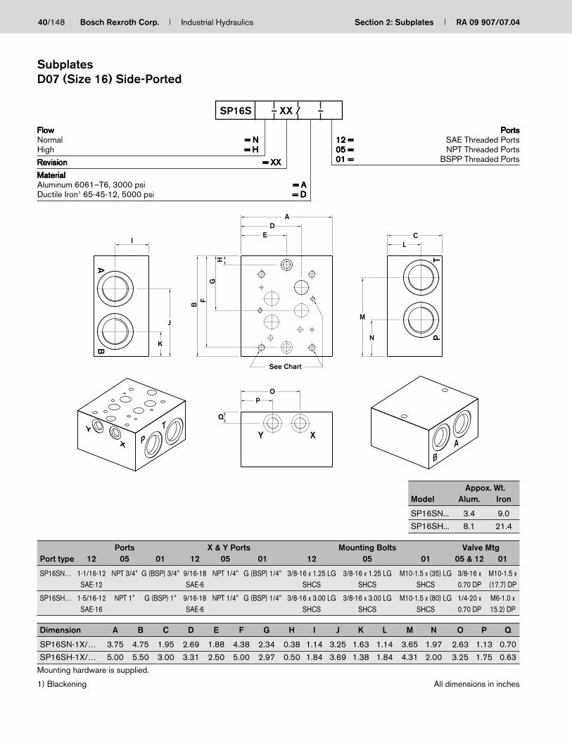
40/148 Bosch Rexroth Corp. Industrial Hydraulics Section 2: Subplates RA 09 907/07.04
Dimension A B C D E F G H I J K L M N O P Q
SP16SN-1X/… 3.75 4.75 1.95 2.69 1.88 4.38 2.34 0.38 1.14 3.25 1.63 1.14 3.65 1.97 2.63 1.13 0.70
SP16SH-1X/… 5.00 5.50 3.00 3.31 2.50 5.00 2.97 0.50 1.84 3.69 1.38 1.84 4.31 2.00 3.25 1.75 0.63
Mounting hardware is supplied.
1) Blackening
FlowFlowFlowFlowFlowNormal = N= N= N= N= NHigh = H= H= H= H= H
RevisionRevisionRevisionRevisionRevision = XX= XX= XX= XX= XX
MaterialMaterialMaterialMaterialMaterialAluminum 6061–T6, 3000 psi = A= A= A= A= ADuctile Iron1 65-45-12, 5000 psi = D= D= D= D= D
PortsPortsPortsPortsPorts12 =12 =12 =12 =12 = SAE Threaded Ports05 =05 =05 =05 =05 = NPT Threaded Ports01 =01 =01 =01 =01 = BSPP Threaded Ports
SP16S – XX / –
Ports X & Y Ports Mounting Bolts Valve MtgPort type 12 05 01 12 05 01 12 05 01 05 & 12 01
SP16SN… 1-1/16-12 NPT 3/4” G (BSP) 3/4” 9/16-18 NPT 1/4” G (BSP) 1/4” 3/8-16 x 1.25 LG 3/8-16 x 1.25 LG M10-1.5 x (35) LG 3/8-16 x M10-1.5 xSAE-12 SAE-6 SHCS SHCS SHCS 0.70 DP (17.7) DP
SP16SH… 1-5/16-12 NPT 1” G (BSP) 1” 9/16-18 NPT 1/4” G (BSP) 1/4” 3/8-16 x 3.00 LG 3/8-16 x 3.00 LG M10-1.5 x (80) LG 1/4-20 x M6-1.0 xSAE-16 SAE-6 SHCS SHCS SHCS 0.70 DP 15.2) DP
See Chart
LC
TP
M
N
A
ED
HG
I
F
A
O
B
J
KB
P
Q
Y XX
Y
P
T
B
A
Appox. Wt.Model Alum. Iron
SP16SN... 3.4 9.0
SP16SH... 8.1 21.4
All dimensions in inches
SubplatesD07 (Size 16) Side-Ported

RA 09 907/07.04 Section 2: Subplates Industrial Hydraulics Bosch Rexroth Corp. 41/148
Dimension A B C D E F G H I J K L M N O P
SP22SN-1X/… 4.50 6.13 2.00 3.37 2.25 5.63 3.53 0.50 1.00 1.00 4.94 3.60 1.60 4.54 2.54 1.19
SP22SH-1X/… 5.00 6.50 3.00 3.62 2.50 6.00 3.73 0.50 1.88 0.63 5.19 4.17 1.73 4.78 2.33 1.31
Mounting hardware is supplied.
1) Blackening
FlowFlowFlowFlowFlowNormal = N= N= N= N= NHigh = H= H= H= H= H
RevisionRevisionRevisionRevisionRevision = XX= XX= XX= XX= XX
MaterialMaterialMaterialMaterialMaterialAluminum 6061–T6, 3000 psi = A= A= A= A= ADuctile Iron1 65-45-12, 5000 psi = D= D= D= D= D
PortsPortsPortsPortsPorts12 =12 =12 =12 =12 = SAE Threaded Ports05 =05 =05 =05 =05 = NPT Threaded Ports01 =01 =01 =01 =01 = BSPP Threaded Ports
SP22S – XX / –
Ports X & Y Ports Mounting Bolts Valve MtgPort type 12 05 01 12 05 01 12 05 01 05 & 12 01
SP22SN… 1-5/16-12 NPT 1” G (BSP) 1” 9/16-18 NPT 1/4” G (BSP) 1/4” 1/2-13 x 1.75 LG 1/2-13 x 1.75 LG M12-1.75 xSAE-16 SAE-6 SHCS SHCS (45) LG SHCS 1/2-13 x M12-1.75
SP22SH… 1-5/8-12 NPT 1-1/4” G (BSP) 1-1/4” 9/16-18 NPT 1/4” G (BSP) 1/4” 1/2-13 x 3.00 LG 1/2-13 x 3.00 LG M12-1.75 x 1.19 DP x (30.2) DP
SAE-20 SAE-6 SHCS SHCS (80) LG SHCS
See Chart
C
JI
AD
EJ
H
I
OP
N
BF
KL
M
G
TX
PY
AB
P
Y
BA
X
T
Appox. Wt.Model Alum. Iron
SP16SN... 5.4 14.3
SP16SH... 9.6 25.4
All dimensions in inches
SubplatesD08 (Size 22) Side-Ported

42/148 Bosch Rexroth Corp. Industrial Hydraulics Section 2: Subplates RA 09 907/07.04

The Drive & Control Company
ServiceAutomation
MobileHydraulics
IndustrialHydraulics
Electric Drivesand Controls
Linear Motion andAssembly Technologies Pneumatics
Section 3Coverplates
RA 09 907/07.04
43
Coverplate Features
– Sizes 6 to 22
– Aluminum and ductile iron
– Includes mounting kit

44/148 Bosch Rexroth Corp. Industrial Hydraulics Section 3: Coverplates RA 09 907/07.04
Section 3 Index
Description Page
Coverplate D03 (Size 6) ...................................................................................................................................................................................................... 45
Coverplate D05 (Size 10) ................................................................................................................................................................................................... 46
Coverplate D07 (Size 16) ................................................................................................................................................................................................... 47
Coverplate D08 (Size 22) ................................................................................................................................................................................................... 48

RA 09 907/07.04 Section 3: Coverplates Industrial Hydraulics Bosch Rexroth Corp. 45/148
ModelApprox. Weight lbs. Dimensions
Mounting Bolts O-Ring SchematicAlum / Duct A B C Thru hole Ø
CP6NN...-120.2 / 0.5 1.30 0.47 0.50 0.218
10-24 x .75 SHCS2-012
CP6NN...-01 M5 x 20mm SHCS
CP6NNH... 0 / 0.8 1.102 0.494 0.75 0.281 1/4-20 x 1.25 SHCS
CP6NP...-120.3 / 0.8 1.30 0.47 0.75 0.218
10-24 x 1.0 SHCS2-012
CP6NP...-01 M5 x 25mm SHCS
CP6PN...-120.2 / 0.5 1.25 0.47 0.50 0.218
10-24 x .75 SHCS2-017
CP6PN...-01 M5 x 20mm SHCS
CP6SN...-120.3 / 0.8 1.30 0.47 0.75 0.218
10-24 x 1.0 SHCS2-012
CP6SN...-01 M5 x 25mm SHCS
CP6CN...-120.2 / 0.5 1.25 0.47 0.50 0.218
10-24 x .75 SHCS2-017
CP6CN...-01 M5 x 20mm SHCS
1) Blackening
Internal ConnectionsInternal ConnectionsInternal ConnectionsInternal ConnectionsInternal ConnectionsParallel P-A & T-B = P= P= P= P= PSeries = S= S= S= S= SCrossover = C= C= C= C= CParallel Circuit (All Ports Blocked) = N= N= N= N= N
Additional PortsAdditional PortsAdditional PortsAdditional PortsAdditional PortsNo Ports = N= N= N= N= N
Ductile Iron1 65-45-12, 9137 psi = H= H= H= H= H
Mounting BoltsMounting BoltsMounting BoltsMounting BoltsMounting Bolts01 =01 =01 =01 =01 = Metric12 =12 =12 =12 =12 = SAE
MaterialMaterialMaterialMaterialMaterialA =A =A =A =A = Aluminum 6061–T6, 3000 psiD =D =D =D =D = Ductile Iron1 65-45-12, 5000 psi
XX =XX =XX =XX =XX = RevisionRevisionRevisionRevisionRevision
CP6 N H – XX / –
All dimensions in inches
C
2.50
See Chart Below
A
1.75
B
Assemblies come with mounting bolts, locating pin, and o-rings.
BPT A
B
P
PT A
(SAE-6)
BPT A
BPT A
P BT A
CoverplateD03 (Size 6)

46/148 Bosch Rexroth Corp. Industrial Hydraulics Section 3: Coverplates RA 09 907/07.04
ModelApprox. Weight lbs. Dimensions Thru Hole
Mounting Bolts O-Ring SchematicAlum / Duct A B C Ø
CP10NN...-12-P 1/4-20 x 1.0 SHCS12 x 2mm
0.5 / 1.3 1.75 0.84 0.50 0.281(P,T,A,B)
CP10NN...-01-P M6 x 25mm SHCS2-013(X,Y)
CP10NP...-12-P 1/4-20 x 1.0 SHCS12 x 2mm
0.7 / 2.0 1.75 0.84 0.75 0.281(P,T,A,B)
CP10NP...-01-P M6 x 25mm SHCS2-013(X,Y)
CP10PN...-12-P 1/4-20 x 2.25 SHCS12 x 2mm
1.7 / 4.6 1.75 0.84 1.70 0.281(P,T,A,B)
CP10PN...-01-P M6 x 55mm SHCS2-013(X,Y)
CP10SN...-12-P 1/4-20 x 1.5 SHCS12 x 2mm
0.9 / 2.5 1.75 0.84 0.95 0.281(P,T,A,B)
CP10SN...-01-P M6 x 35mm SHCS2-013(X,Y)
CP10CN...-12-P 1/4-20 x 2.25 SHCS12 x 2mm
1.7 / 4.6 1.75 0.84 1.70 0.281(P,T,A,B)
CP10CN...-01-P M6 x 55mm SHCS2-013(X,Y)
1) Blackening
Internal ConnectionsInternal ConnectionsInternal ConnectionsInternal ConnectionsInternal ConnectionsParallel P–A & T–B = P= P= P= P= PSeries = S= S= S= S= SCrossover = C= C= C= C= CParallel Circuit (All Ports Blocked) = N= N= N= N= N
Additional PortsAdditional PortsAdditional PortsAdditional PortsAdditional PortsNo Ports = N= N= N= N= N
RevisionRevisionRevisionRevisionRevision = XX= XX= XX= XX= XX
P =P =P =P =P = Pilot PortsPilot PortsPilot PortsPilot PortsPilot Ports
Mounting BoltsMounting BoltsMounting BoltsMounting BoltsMounting Bolts01 =01 =01 =01 =01 = Metric12 =12 =12 =12 =12 = SAE
MaterialMaterialMaterialMaterialMaterialA =A =A =A =A = Aluminum 6061–T6, 3000 psiD =D =D =D =D = Ductile Iron1 65-45-12, 5000 psi
CP10 – XX / – – /P
All dimensions in inches
CB
A
3.50
3.00
Assemblies come with mounting bolts and o-rings.
YTBPATX
T YP B
P
T AX
(SAE-6)
YTBPATX
YTBPATX
YTBPATX
CoverplateD05 (Size 10)

RA 09 907/07.04 Section 3: Coverplates Industrial Hydraulics Bosch Rexroth Corp. 47/148
Internal ConnectionsInternal ConnectionsInternal ConnectionsInternal ConnectionsInternal ConnectionsParallel P–A & T–B = P= P= P= P= PSeries = S= S= S= S= SCrossover = C= C= C= C= CParallel Circuit (All ports blocked) = N= N= N= N= N
Additional PortsAdditional PortsAdditional PortsAdditional PortsAdditional PortsNo Ports = N= N= N= N= N
RevisionRevisionRevisionRevisionRevision = XX= XX= XX= XX= XX
Mounting BoltsMounting BoltsMounting BoltsMounting BoltsMounting Bolts01 =01 =01 =01 =01 = Metric12 =12 =12 =12 =12 = SAE
MaterialMaterialMaterialMaterialMaterialA =A =A =A =A = Aluminum 6061–T6, 3000 psiD =D =D =D =D = Ductile Iron1 65-45-12, 5000 psi
CP16 – XX / –
All dimensions in inches
CA
3.50
B
5.00
Assemblies come with mounting bolts, locating pin, and o-rings.
ModelApprox. Weight lbs. Dimensions Thru Hole
Mounting Bolts O-Ring SchematicAlum / Duct A B C Mounting
CP16NN...-12(2x) 1/4-20 x 1.50 SHCS 22 x 2.5mm
1.6 / 4.3 2.53 0.94 0.950.281 3/8-16 x 1.50 SHCS (P,T,A,B)
CP16NN...-01(4x) M6 x 25mm SHCS 10 x 2mm
0.406 M10 x 40mm SHCS (X,Y)
CP16NP...-12(2x) 1/4-20 x 1.50 SHCS 22 x 2.5mm
1.6 / 4.3 2.53 0.94 0.950.281 3/8-16 x 1.50 SHCS (P,T,A,B)
CP16NP...-01(4x) M6 x 25mm SHCS 10 x 2mm
0.406 M10 x 40mm SHCS (X,Y)
CP16PN...-12(2x) 1/4-20 x 2.75 SHCS 22 x 2.5mm
3.7 / 10 2.53 0.94 2.200.281 3/8-16 x 2.75 SHCS (P,T,A,B)
CP16PN...-01(4x) M6 x 70mm SHCS 10 x 2mm
0.406 M10 x 70mm SHCS (X,Y)
CP16SN...-12(2x) 1/4-20 x 2.00 SHCS 22 x 2.5mm
2.4 / 6.5 2.53 0.94 1.450.281 3/8-16 x 2.00 SHCS (P,T,A,B)
CP16SN...-01(4x) M6 x 50mm SHCS 10 x 2mm
0.406 M10 x 50mm SHCS (X,Y)
CP16CN...-12(2x) 1/4-20 x 2.25 SHCS 22 x 2.5mm
2.9 / 7.7 2.53 0.94 1.700.281 3/8-16 x 2.25 SHCS (P,T,A,B)
CP16CN...-01(4x) M6 x 55mm SHCS 10 x 2mm
0.406 M10 x 55mm SHCS (X,Y)
1) Blackening
TPB AYX
TPB AYX
P
TPB AYX
(SAE-6)
TPB AYX
P BT A
CoverplateD07 (Size 16)

48/148 Bosch Rexroth Corp. Industrial Hydraulics Section 3: Coverplates RA 09 907/07.04
Internal ConnectionsInternal ConnectionsInternal ConnectionsInternal ConnectionsInternal ConnectionsParallel P–A & T–B = P= P= P= P= PSeries = S= S= S= S= SCrossover = C= C= C= C= CParallel Circuit (All Ports Blocked) = N= N= N= N= N
Additional PortsAdditional PortsAdditional PortsAdditional PortsAdditional PortsNo Ports = N= N= N= N= N
RevisionRevisionRevisionRevisionRevision = XX= XX= XX= XX= XX
Mounting BoltsMounting BoltsMounting BoltsMounting BoltsMounting Bolts01 =01 =01 =01 =01 = Metric12 =12 =12 =12 =12 = SAE
MaterialMaterialMaterialMaterialMaterialA =A =A =A =A = Aluminum 6061–T6, 3000 psiD =D =D =D =D = Ductile Iron1 65-45-12, 5000 psi
CP22 – XX / –
All dimensions in inches
C
A
6.00
B
4.50
Assemblies come with mounting bolts, locating pin, and o-rings.
ModelApprox. Weight lbs. Dimensions Thru Hole
Mounting Bolts O-Ring SchematicAlum / Duct A B C Ø
CP22NN...-12 1/2-13 x 1.75 SHCS27 x 3mm
2.5 / 6.6 2.59 3.31 0.95 0.531(P,T,A,B)
CP22NN...-01 M12 x 45mm SHCS19 x 3mm
(X,Y)
CP22NP...-12 1/2-13 x 1.75 SHCS27 x 3mm
2.5 / 6.6 2.59 3.37 0.95 0.531(P,T,A,B)
CP22NP...-01 M12 x 45mm SHCS19 x 3mm
(X,Y)
27 x 3mmCP22PN...-12 1/2-13 x 3.25 SHCS (P,T,A,B)
2.54 3.37 2.45 0.53119 x 3mm
6.4 / 17.1 (X,Y)CP22PN...-01 M12 x 80mm SHCS 2-231
(P/A)
CP22SN...-12 1/2-13 x 2.50 SHCS27 x 3mm
4.4 / 11.9 2.54 3.37 1.70 0.531(P,T,A,B)
CP22SN...-01 M12 x 65mm SHCS19 x 3mm
(X,Y)
CP22CN...-12 1/2-13 x 2.75 SHCS27 x 3mm
5.1 / 13.6 2.54 3.37 1.95 0.531(P,T,A,B)
CP22CN...-01 M12 x 70mm SHCS19 x 3mm
(X,Y)
1) Blackening
TPB AYX
P
TPB AYX
(SAE-6)
TPB AYX
TPB AYX
TPB AYX
CoverplateD08 (Size 22)

The Drive & Control Company
ServiceAutomation
MobileHydraulics
IndustrialHydraulics
Electric Drivesand Controls
Linear Motion andAssembly Technologies Pneumatics
Section 4Sandwich Plates
RA 09 907/07.04
49
Sandwich Plate Features
– Sizes 6 to 22
– Aluminum and ductile iron
– For full flow and test port tap-in
– No mounting kit, but set of o-rings included
– SAE, BSPP, or NPT porting

50/148 Bosch Rexroth Corp. Industrial Hydraulics Section 4: Sandwich Plates RA 09 907/07.04
Section 4 Index
Description Page
Tapping Plate D03 (Size 6) ................................................................................................................................................................................................ 51
Spacer Plate D03 (Size 6) .................................................................................................................................................................................................. 52
Tapping Plate D05 (Size 10) .............................................................................................................................................................................................. 53
Spacer Plate D05 (Size 10) ............................................................................................................................................................................................... 54
Tapping Plate D07 (Size 16) .............................................................................................................................................................................................. 55
Tapping Plate D08 (Size 22) .............................................................................................................................................................................................. 56
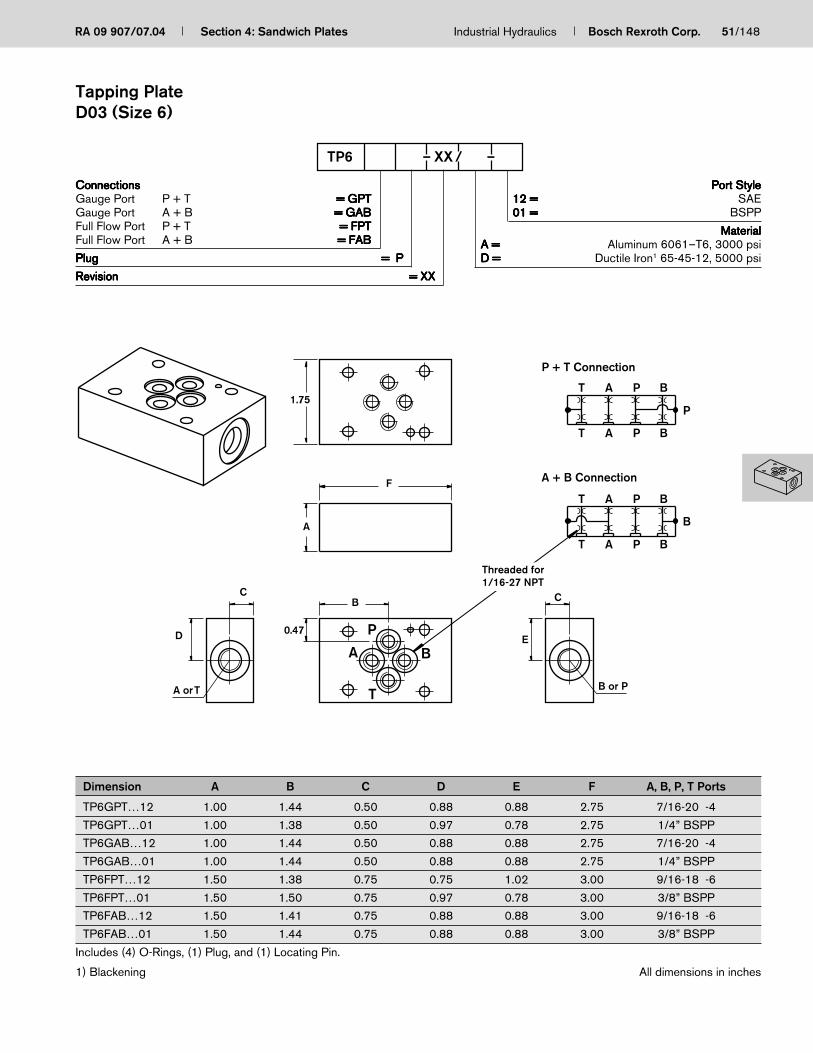
RA 09 907/07.04 Section 4: Sandwich Plates Industrial Hydraulics Bosch Rexroth Corp. 51/148
ConnectionsConnectionsConnectionsConnectionsConnectionsGauge Port P + T = GPT= GPT= GPT= GPT= GPTGauge Port A + B = GAB= GAB= GAB= GAB= GABFull Flow Port P + T = FPT= FPT= FPT= FPT= FPTFull Flow Port A + B = FAB= FAB= FAB= FAB= FAB
PlugPlugPlugPlugPlug = P= P= P= P= P
RevisionRevisionRevisionRevisionRevision = XX= XX= XX= XX= XX
Port StylePort StylePort StylePort StylePort Style12 =12 =12 =12 =12 = SAE01 =01 =01 =01 =01 = BSPP
MaterialMaterialMaterialMaterialMaterialA =A =A =A =A = Aluminum 6061–T6, 3000 psiD =D =D =D =D = Ductile Iron1 65-45-12, 5000 psi
TP6 – XX / –
Dimension A B C D E F A, B, P, T Ports
TP6GPT…12 1.00 1.44 0.50 0.88 0.88 2.75 7/16-20 -4
TP6GPT…01 1.00 1.38 0.50 0.97 0.78 2.75 1/4” BSPP
TP6GAB…12 1.00 1.44 0.50 0.88 0.88 2.75 7/16-20 -4
TP6GAB…01 1.00 1.44 0.50 0.88 0.88 2.75 1/4” BSPP
TP6FPT…12 1.50 1.38 0.75 0.75 1.02 3.00 9/16-18 -6
TP6FPT…01 1.50 1.50 0.75 0.97 0.78 3.00 3/8” BSPP
TP6FAB…12 1.50 1.41 0.75 0.88 0.88 3.00 9/16-18 -6
TP6FAB…01 1.50 1.44 0.75 0.88 0.88 3.00 3/8” BSPP
Includes (4) O-Rings, (1) Plug, and (1) Locating Pin.
1) Blackening
ED
C
F
0.47
B
A
1.75
B or P
C
A or T
P
P
P
T A
T
P + T Connection
A + B Connection
A
B
B
B
A
AT
T
P
P
B
B
A
P
B
T
Threaded for1/16-27 NPT
All dimensions in inches
Tapping PlateD03 (Size 6)

52/148 Bosch Rexroth Corp. Industrial Hydraulics Section 4: Sandwich Plates RA 09 907/07.04
Thickness, Dim. “A”Thickness, Dim. “A”Thickness, Dim. “A”Thickness, Dim. “A”Thickness, Dim. “A”===== 3/43/43/43/43/4″===== 11111″===== 1-1/41-1/41-1/41-1/41-1/4″===== 1-1/21-1/21-1/21-1/21-1/2″===== 1-3/41-3/41-3/41-3/41-3/4″===== 22222″===== 2-1/42-1/42-1/42-1/42-1/4″===== 2-1/22-1/22-1/22-1/22-1/2″===== 2-3/42-3/42-3/42-3/42-3/4″===== 33333″
Port StylePort StylePort StylePort StylePort Style12 =12 =12 =12 =12 = SAE
MaterialMaterialMaterialMaterialMaterialA =A =A =A =A = Aluminum 6061–T6, 3000 psiD =D =D =D =D = Ductile Iron1 65-45-12, 5000 psi
XX =XX =XX =XX =XX = Revision
SB6 – XX / –
Spacer BlockD03 (Size 6)
A1.75
0.47
2.75
PAT
AT P B
B
1.38
D03 (Valve)
D03 (Manifold)
Includes (4) O-rings and (1) Locating Pin.
Mounting hardware is not included.
1) Blackening All dimensions in inches

RA 09 907/07.04 Section 4: Sandwich Plates Industrial Hydraulics Bosch Rexroth Corp. 53/148
ConnectionsConnectionsConnectionsConnectionsConnectionsGauge Port P + T ===== GPTGPTGPTGPTGPTGauge Port A + B ===== GABGABGABGABGABGauge Port X + Y ===== GXYGXYGXYGXYGXYFull Flow Port P + T ===== FPTFPTFPTFPTFPT **********Full Flow Port A + B ===== FABFABFABFABFAB
RevisionRevisionRevisionRevisionRevision = XX= XX= XX= XX= XX
Port StylePort StylePort StylePort StylePort Style12 =12 =12 =12 =12 = SAE01 =01 =01 =01 =01 = BSPP
MaterialMaterialMaterialMaterialMaterialA =A =A =A =A = Aluminum 6061–T6, 3000 psiD =D =D =D =D = Ductile Iron1 65-45-12, 5000 psi
TP10 – XX / –
Dimension A B C D E A, B, P, T Ports
TP10GPT…12 1.00 2.50 0.50 1.00 1.20 7/16-20 -4
TP10GPT…01 1.00 2.50 0.50 1.00 1.20 1/4” BSPP
TP10GAB…12 1.00 2.50 0.50 1.37 1.37 7/16-20 -4
TP10GAB…01 1.00 2.50 0.50 1.37 1.37 1/4” BSPP
TP10GXY…12 1.00 2.50 0.50 1.85 1.85 7/16-20 -4
TP10GXY…01 1.00 2.50 0.50 1.85 1.85 1/4” BSPP
TP10FPT…12 2.00 2.75 1.00 1.00 1.20 7/8-14 -10
TP10FPT…01 2.00 2.75 1.00 1.00 1.20 1/2” BSPP
TP10FAB…12 2.00 2.50 1.00 1.37 1.37 7/8-14 -10
TP10FAB…01 2.00 2.50 1.00 1.37 1.37 1/2” BSPP
Includes (7) O-Rings and (1) Plug.
1) Blackening **FPT option has a side tank port only
P, B, or YT, A, or X
D E
CC
2.03
B
2.75
A
5.00
X T A P B T Y
X AT P B T Y
AX T P B T Y
AX T P B T Y
A
AX T
X T
P B T
P B T
Y
Y
T
X
A B T
Y
P
P + T Connection
A + B Connection
X + Y Connection
T
A
X
P
B
Y
All dimensions in inches
Tapping PlateD05 (Size 10)

54/148 Bosch Rexroth Corp. Industrial Hydraulics Section 4: Sandwich Plates RA 09 907/07.04
(manifold)D05
(valve)D05
Y
Y
X
X
3.50
1.75
3.00
2.16
A
PAT
AT P B
B
Thickness, Dim. “A”Thickness, Dim. “A”Thickness, Dim. “A”Thickness, Dim. “A”Thickness, Dim. “A” ===== 1/21/21/21/21/2″===== 3/43/43/43/43/4″===== 11111″===== 1-1/41-1/41-1/41-1/41-1/4″===== 1-1/21-1/21-1/21-1/21-1/2″===== 1-3/41-3/41-3/41-3/41-3/4″===== 22222″===== 2-1/42-1/42-1/42-1/42-1/4″===== 2-1/22-1/22-1/22-1/22-1/2″===== 2-3/42-3/42-3/42-3/42-3/4″===== 33333″
Port StylePort StylePort StylePort StylePort Style12 =12 =12 =12 =12 = SAE
MaterialMaterialMaterialMaterialMaterialA =A =A =A =A = Aluminum 6061–T6, 3000 psiD =D =D =D =D = Ductile Iron1 65-45-12, 5000 psi
XX =XX =XX =XX =XX = Revision
SB10 – XX / –
Spacer BlockD05 (Size 10)
Includes (7) O-rings.
Mounting hardware is not included.
1) Blackening All dimensions in inches

RA 09 907/07.04 Section 4: Sandwich Plates Industrial Hydraulics Bosch Rexroth Corp. 55/148
ConnectionsConnectionsConnectionsConnectionsConnectionsGauge Port P + T = GPT= GPT= GPT= GPT= GPTGauge Port A + B = GAB= GAB= GAB= GAB= GABGauge Port X + Y = GXY= GXY= GXY= GXY= GXYFull Flow Port P + T = FPT= FPT= FPT= FPT= FPTFull Flow Port A + B = FAB= FAB= FAB= FAB= FAB
RevisionRevisionRevisionRevisionRevision = XX= XX= XX= XX= XX
Port StylePort StylePort StylePort StylePort Style12 =12 =12 =12 =12 = SAE01 =01 =01 =01 =01 = BSPP
MaterialMaterialMaterialMaterialMaterialA =A =A =A =A = Aluminum 6061–T6, 3000 psiD =D =D =D =D = Ductile Iron1 65-45-12, 5000 psi
TP16 – XX / –
Dimension A B C D E F A, B, P, T, X, Y Ports
TP16GPT…12 1.00 2.78 0.50 1.83 1.12 – 7/16-20 -4
TP16GPT…01 1.00 2.78 0.50 1.83 1.12 – 1/4” BSPP
TP16GAB…12 1.00 2.78 0.50 1.63 2.38 – 7/16-20 -4
TP16GAB…01 1.00 1.78 0.50 1.63 2.38 – 1/4” BSPP
TP16GXY…12 1.00 2.78 0.50 2.47 – 1.02 7/16-20 -4
TP16GXY…01 1.00 2.78 0.50 2.47 – 1.02 1/4” BSPP
TP16FPT…12 3.00 2.53 1.50 1.58 1.40 – 1-5/16-12 -16
TP16FPT…01 3.00 2.53 1.50 1.58 1.40 – 1” BSPP
TP16FAB…12 3.00 2.53 1.50 1.98 2.12 – 1-5/16-12 -16
TP16FAB…01 3.00 2.53 1.50 1.98 2.12 – 1” BSPP
Includes (6) O-Rings, (1) Plug, and Locating Pin.
1) Blackening
A or TB, P,or Y
X Porton GXY
3.50
A
E
C
D
F
C
0.94
B
5.50
X Y B P T A
X BY P T A
X Y B P
X Y B P
T A
T A
X Y B P
X Y B P
T A
T A
X TA
PB
Y
A + B Connection
X + Y Connection
P
B
Y
T
A
X
All dimensions in inches
Tapping PlateD07 (Size 16)

56/148 Bosch Rexroth Corp. Industrial Hydraulics Section 4: Sandwich Plates RA 09 907/07.04
ConnectionsConnectionsConnectionsConnectionsConnectionsGauge Port P + T = GPT= GPT= GPT= GPT= GPTGauge Port A + B = GAB= GAB= GAB= GAB= GABGauge Port X + Y = GXY= GXY= GXY= GXY= GXYFull Flow Port P + T = FPT= FPT= FPT= FPT= FPTFull Flow Port A + B = FAB= FAB= FAB= FAB= FAB
RevisionRevisionRevisionRevisionRevision = XX= XX= XX= XX= XX
Port StylePort StylePort StylePort StylePort Style12 =12 =12 =12 =12 = SAE01 =01 =01 =01 =01 = BSPP
MaterialMaterialMaterialMaterialMaterialA =A =A =A =A = Aluminum 6061–T6, 3000 psiD =D =D =D =D = Ductile Iron1 65-45-12, 5000 psi
TP22 – XX / –
Dimension A B C D A, B, P, T, X, Y Ports
TP22GPT…12 1.00 0.50 3.38 2.25 7/16-20 -4
TP22GPT…01 1.00 0.50 3.38 2.25 1/4” BSPP
TP22GAB…12 1.00 0.50 2.25 1.13 7/16-20 -4
TP22GAB…01 1.00 0.50 2.25 1.13 1/4” BSPP
TP22GXY…12 1.00 0.50 1.19 3.31 7/16-20 -4
TP22GXY…01 1.00 0.50 1.19 3.31 1/4” BSPP
TP22FPT…12 4.00 2.00 2.82 1.73 1-5/8-12 -20
TP22FPT…01 4.00 2.00 2.82 2.00 1-1/4” BSPP
TP22FAB…12 4.00 2.00 4.67 1.70 1-5/8-12 -20
TP22FAB…01 4.00 2.00 2.50 1.70 1-1/4” BSPP
Includes (6) O-Rings, (1) Plug, and (1) Locating Pin.
1) Blackening All dimensions in inches
3.97
P, B, or Y
D
C
BB
4.50
3.38
A
7.00X T A P B T Y
X AT P B T Y
AX T P B T Y
AX T P B T Y
A
AX T
X T
P B T
P B T
Y
Y
T
X
P
A B
YT, A, or X
P + T Connection
A + B Connection
X + Y Connection
T
A
X
P
B
Y
Tapping PlateD08 (Size 22)

The Drive & Control Company
ServiceAutomation
MobileHydraulics
IndustrialHydraulics
Electric Drivesand Controls
Linear Motion andAssembly Technologies Pneumatics
Section 5Valve Adaptors
RA 09 907/07.04
57
Valve Adaptor Features
– Size adaption from sizes 6 through 32
– Includes some Rexroth style patterns and others
– Aluminum and ductile iron
– Includes mounting kit

58/148 Bosch Rexroth Corp. Industrial Hydraulics Section 5: Valve Adaptors RA 09 907/07.04
Section 5 Index
Description Page
Valve Adaptor D03 (Size 6) to D05 (Size 10) ................................................................................................................................................................ 59
Valve Adaptor D03 (Size 6) to D07 (Size 16) ................................................................................................................................................................ 60
Valve Adaptor D05 (Size 10) to D07 (Size 16) ............................................................................................................................................................. 61
Valve Adaptor D03 (Size 6) to D08 (Size 22) ................................................................................................................................................................ 62
Valve Adaptor D05 (Size 10) to D08 (Size 22) ............................................................................................................................................................. 63
Valve Adaptor D07 (Size 16) to D08 (Size 22) ............................................................................................................................................................. 64
Valve Adaptor D03 (Size 6) to WE5 (Size 5) ................................................................................................................................................................. 65
Valve Adaptor D03 (Size 6) to SE6 .................................................................................................................................................................................. 66
Valve Adaptor FRM6 to FRM5 ........................................................................................................................................................................................... 67
Valve Adaptor DBET-5X to DBET-3X .............................................................................................................................................................................. 68
Valve Adaptor D03 (Size 6) to Moog Size 72 ................................................................................................................................................................ 69
Valve Adaptor D05 (Size 10) to D06 ............................................................................................................................................................................... 70
Valve Adaptor D06 to D08 (Size 22) ............................................................................................................................................................................... 71
Valve Adaptor D08 (Size 22) to D10 (Size 32) ............................................................................................................................................................. 72
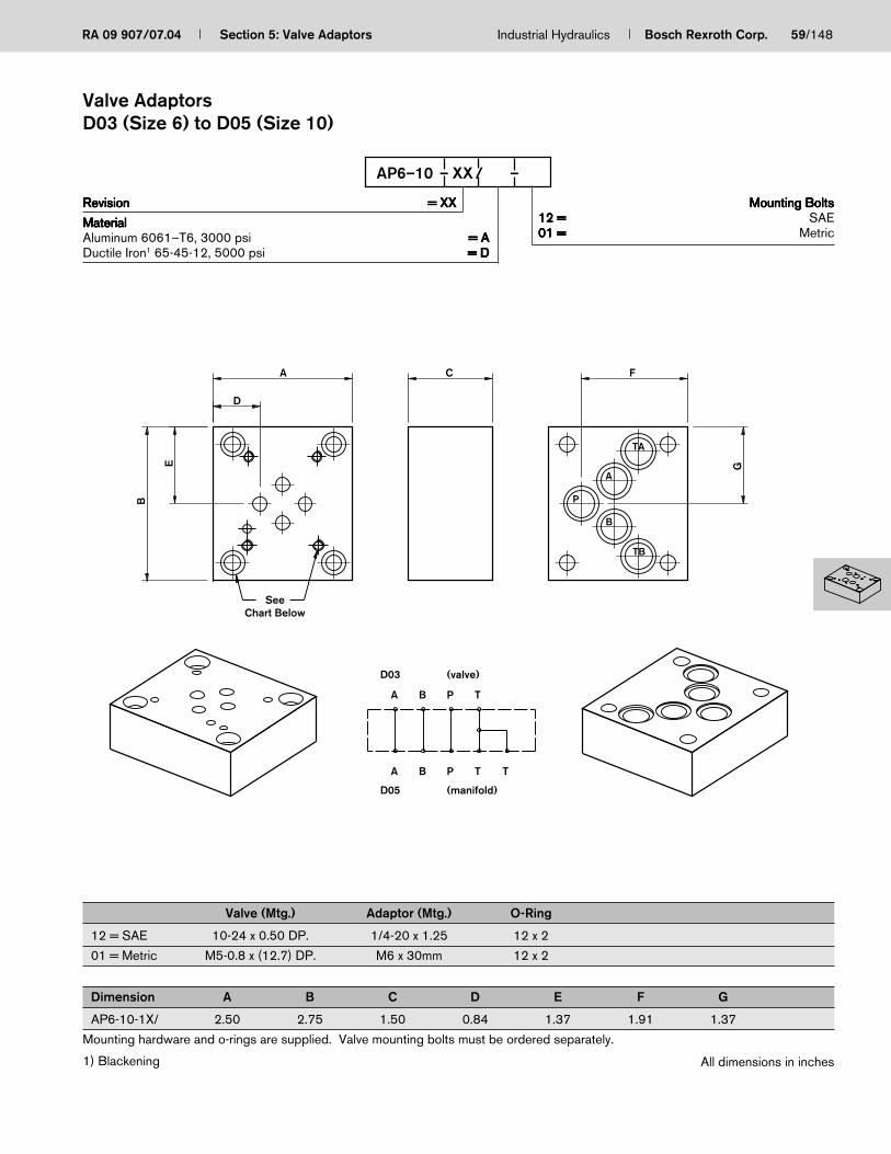
RA 09 907/07.04 Section 5: Valve Adaptors Industrial Hydraulics Bosch Rexroth Corp. 59/148
RevisionRevisionRevisionRevisionRevision = XX= XX= XX= XX= XX
MaterialMaterialMaterialMaterialMaterialAluminum 6061–T6, 3000 psi = A= A= A= A= ADuctile Iron1 65-45-12, 5000 psi = D= D= D= D= D
Mounting BoltsMounting BoltsMounting BoltsMounting BoltsMounting Bolts12 =12 =12 =12 =12 = SAE01 =01 =01 =01 =01 = Metric
AP6–10 – XX / –
Valve (Mtg.) Adaptor (Mtg.) O-Ring
12 = SAE 10-24 x 0.50 DP. 1/4-20 x 1.25 12 x 2
01 = Metric M5-0.8 x (12.7) DP. M6 x 30mm 12 x 2
Dimension A B C D E F G
AP6-10-1X/ 2.50 2.75 1.50 0.84 1.37 1.91 1.37
Mounting hardware and o-rings are supplied. Valve mounting bolts must be ordered separately.
1) Blackening
G
FC
B
E
D
A
TA
A
P
B
TB
SeeChart Below
(manifold)
(valve)
D05
D03
TPA B T
TPBA
All dimensions in inches
Valve AdaptorsD03 (Size 6) to D05 (Size 10)

60/148 Bosch Rexroth Corp. Industrial Hydraulics Section 5: Valve Adaptors RA 09 907/07.04
RevisionRevisionRevisionRevisionRevision = XX= XX= XX= XX= XX
MaterialMaterialMaterialMaterialMaterialAluminum 6061–T6, 3000 psi = A= A= A= A= ADuctile Iron1 65-45-12, 5000 psi = D= D= D= D= D
Mounting BoltsMounting BoltsMounting BoltsMounting BoltsMounting Bolts12 =12 =12 =12 =12 = SAE01 =01 =01 =01 =01 = Metric
AP6–16 – XX / –
Valve (Mtg.) Adaptor (Mtg.) Adaptor (Mtg.) O-Ring O-Ring
12 = SAE 10-24 x 0.50 DP. 3/8-16 x 2.25 1/4-20 x 2.50 10 x 2 22 x 2.5
01 = Metric M5-0.8 x (12.7) DP. M10 x 30mm M6 x 40mm 10 x 2 22 x 2.5
Dimension A B C D E F G
AP6-16-1X/ 3.50 5.50 2.5 0.98 2.6 2.56 2.72
Mounting hardware and o-rings are supplied. Valve mounting bolts must be ordered separately.
1) Blackening
F
CA
D
GE
B
T
P
A
BX
AP
BT
Y
(valve)
PBA
D03
T
X
(manifold)
YPBA
D07
T
SeeChart Below
All dimensions in inches
Valve AdaptorsD03 (Size 6) to D07 (Size 16)

RA 09 907/07.04 Section 5: Valve Adaptors Industrial Hydraulics Bosch Rexroth Corp. 61/148
RevisionRevisionRevisionRevisionRevision = XX= XX= XX= XX= XX
MaterialMaterialMaterialMaterialMaterialAluminum 6061–T6, 3000 psi = A= A= A= A= ADuctile Iron1 65-45-12, 5000 psi = D= D= D= D= D
Mounting BoltsMounting BoltsMounting BoltsMounting BoltsMounting Bolts12 =12 =12 =12 =12 = SAE01 =01 =01 =01 =01 = Metric
AP10–16 – XX / –
Valve (Mtg.) Adaptor (Mtg.) Adaptor (Mtg.) O-Ring O-Ring
12 = SAE 10-24 x 0.60 DP. 3/8-16 x 2.25 1/4-20 x 2.50 10 x 2 22 x 2.5
01 = Metric M6-1.0 x (15.2) DP. M10 x 30mm M6 x 40mm 10 x 2 22 x 2.5
Dimension A B C D E F G
AP10-16-1X/ 3.50 5.50 2.50 2.56 2.6 2.56 2.72
Mounting hardware and o-rings are supplied. Valve mounting bolts must be ordered separately.
1) Blackening
T
P
A
BX
Y
A
P
B
Y
X
T
C
G
F
A
E
B
D
YX
Y
P T
(valve)
BA
D05
TP X
(manifold)D07
BA
SeeChart Below
Threaded for1/16-27 NPT
All dimensions in inches
Valve AdaptorsD05 (Size 10) to D07 (Size 16)

62/148 Bosch Rexroth Corp. Industrial Hydraulics Section 5: Valve Adaptors RA 09 907/07.04
RevisionRevisionRevisionRevisionRevision = XX= XX= XX= XX= XX
MaterialMaterialMaterialMaterialMaterialAluminum 6061–T6, 3000 psi = A= A= A= A= ADuctile Iron1 65-45-12, 5000 psi = D= D= D= D= D
Mounting BoltsMounting BoltsMounting BoltsMounting BoltsMounting Bolts12 =12 =12 =12 =12 = SAE01 =01 =01 =01 =01 = Metric
AP6–22 – XX / –
Valve (Mtg.) Adaptor (Mtg.) O-Ring O-Ring
12 = SAE 10-24 x 0.50 DP. 1/2-13 x 1.50 19 x 3 27 x 3
01 = Metric M5-0.8 x (12.7) DP. M12 x 40mm 19 x 3 27 x 3
Dimension A B C D E F G
AP6-22-1X/ 4.63 6.00 1.50 2.02 3.72 3.43 3.46
Mounting hardware and o-rings are supplied. Valve mounting bolts must be ordered separately.
1) Blackening
T
(valve)
PBA
D03
Y LXT
(manifold)
PBA
D08
F
G
D
A C
E
B
SeeChart Below
AT
B
P
L
Y
X
A
T
B
P
All dimensions in inches
Valve AdaptorsD03 (Size 6) to D08 (Size 22)

RA 09 907/07.04 Section 5: Valve Adaptors Industrial Hydraulics Bosch Rexroth Corp. 63/148
RevisionRevisionRevisionRevisionRevision = XX= XX= XX= XX= XX
MaterialMaterialMaterialMaterialMaterialAluminum 6061–T6, 3000 psi = A= A= A= A= ADuctile Iron1 65-45-12, 5000 psi = D= D= D= D= D
Mounting BoltsMounting BoltsMounting BoltsMounting BoltsMounting Bolts12 =12 =12 =12 =12 = SAE01 =01 =01 =01 =01 = Metric
AP10–22 – XX / –
Valve (Mtg.) Adaptor (Mtg.) O-Ring O-Ring
12 = SAE 1/4-20 x 0.60 DP. 1/2-13 x 1.50 19 x 3 27 x 3
01 = Metric M6-1.0 x (15.2) DP. M12 x 40mm 19 x 3 27 x 3
Dimension A B C D E F G
AP10-22-1X/ 4.63 6.00 1.50 3.19 3.47 3.43 3.46
Mounting hardware and o-rings are supplied. Valve mounting bolts must be ordered separately.
1) Blackening
Threaded for Plug1/16-27 NPT
T
(valve)
XT
(manifold)
Y L
X YPB
D05
A
PBA
D08
G
FCA
D
B
E
SeeChart Below
A
X
Y
T
B
P
L
X
Y
A
T
B
P
All dimensions in inches
Valve AdaptorsD05 (Size 10) to D08 (Size 22)

64/148 Bosch Rexroth Corp. Industrial Hydraulics Section 5: Valve Adaptors RA 09 907/07.04
RevisionRevisionRevisionRevisionRevision = XX= XX= XX= XX= XX
MaterialMaterialMaterialMaterialMaterialAluminum 6061–T6, 3000 psi = A= A= A= A= ADuctile Iron1 65-45-12, 5000 psi = D= D= D= D= D
Mounting BoltsMounting BoltsMounting BoltsMounting BoltsMounting Bolts12 =12 =12 =12 =12 = SAE01 =01 =01 =01 =01 = Metric
AP16–22 – XX / –
Valve (Mtg.) Adaptor (Mtg.) O-Ring O-Ring
12 = SAE 1/4-20 x 0.70 DP. 1/2-13 x 1.50 19 x 3 27 x 33/8-16 x 0.70 DP.
01 = Metric M6-1.0 x (17.7) DP. M12 x 40mm 19 x 3 27 x 3M10-1.5 x (17.7) DP.
Dimension A B C D E F G
AP16-22-1X/ 4.50 6.00 1.75 3.06 2.97 3.38 3.47
Mounting hardware and o-rings are supplied. Valve mounting bolts must be ordered separately.
1) Blackening
C
G
F
A
E
B
D
X YTP
(valve)
BA
D07
Y LXTPBA
D08 (manifold)
SeeChart Below
A
Y
X
T
P
B
L
X
Y
A
T
B
P
All dimensions in inches
Valve AdaptorsD07 (Size 16) to D08 (Size 22)
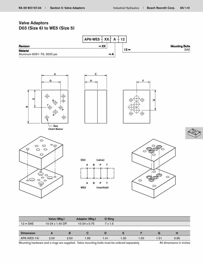
RA 09 907/07.04 Section 5: Valve Adaptors Industrial Hydraulics Bosch Rexroth Corp. 65/148
RevisionRevisionRevisionRevisionRevision = XX= XX= XX= XX= XX
MaterialMaterialMaterialMaterialMaterialAluminum 6061–T6, 3000 psi = A= A= A= A= A
Mounting BoltsMounting BoltsMounting BoltsMounting BoltsMounting Bolts12 =12 =12 =12 =12 = SAE
AP6-WE5 – XX / A – 12
Valve (Mtg.) Adaptor (Mtg.) O-Ring
12 = SAE 10-24 x 1.40 DP. 10-24 x 0.75 7 x 1.5
Dimension A B C D E F G H
AP6-WE5-1X/ 2.00 2.50 1.65 1.41 1.30 1.00 1.51 0.95
Mounting hardware and o-rings are supplied. Valve mounting bolts must be ordered separately.
H F
G
CA
D
E
B
(manifold)
(valve)
WE5
D03
PA B T
TPBA
SeeChart Below
A
T
B
P
All dimensions in inches
Valve AdaptorsD03 (Size 6) to WE5 (Size 5)

66/148 Bosch Rexroth Corp. Industrial Hydraulics Section 5: Valve Adaptors RA 09 907/07.04
RevisionRevisionRevisionRevisionRevision = XX= XX= XX= XX= XX
MaterialMaterialMaterialMaterialMaterialDuctile Iron1 65-45-12, 5000 psi = D= D= D= D= DDuctile Iron 65-45-12, 9137 psi = S= S= S= S= S
Mounting BoltsMounting BoltsMounting BoltsMounting BoltsMounting Bolts12 =12 =12 =12 =12 = SAE
AP6-SE6 – XX / – 12
Valve (Mtg.) Adaptor (Mtg.) O-Ring
AP6-SE6-1X/…D 10-24 x 0.60 DP. 1/4-20 x 1.75 2-012
AP6-SE6-1X/…S 1/4-20 x 0.65 DP. 1/4-20 x 1.75 2-012
Dimension A B C D E F G
AP6-SE6-1X/ 2.40 2.75 1.80 1.65 1.28 1.79 1.81
Mounting hardware and o-rings are supplied. Valve mounting bolts must be ordered separately.
1) Blackening
F
C
G
A
D
E
B
A
B
TP
A
B
T
P
A
A
(manifold)
(valve)
SE6
SEW6
PB T
TPB
SeeChart Below
Threaded for1/16-27 NPT
All dimensions in inches
Valve AdaptorsSEW6 to SE6

RA 09 907/07.04 Section 5: Valve Adaptors Industrial Hydraulics Bosch Rexroth Corp. 67/148
RevisionRevisionRevisionRevisionRevision = XX= XX= XX= XX= XX
MaterialMaterialMaterialMaterialMaterialAluminum 6061–T6, 3000 psi = A= A= A= A= ADuctile Iron1 65-45-12, 5000 psi = D= D= D= D= D
Mounting BoltsMounting BoltsMounting BoltsMounting BoltsMounting Bolts12 =12 =12 =12 =12 = SAE
APFRM6-FRM5 – XX / – 12
Valve (Mtg.) Adaptor (Mtg.) O-Ring
12 = SAE 10-24 x 0.45 DP. 10-24 x 1-1/4 12 x 2.5
Dimension A B C D E F G
APFRM6-FRM5-1X/ 2.36 2.36 1.18 0.79 1.18 1.85 0.75
Mounting hardware and o-rings are supplied. Valve mounting bolts must be ordered separately.
1) Blackening
F
G
D
E
B
A C
A
A
(manifold)
(valve)
FRM5
FRM6
B
B
All dimensions in inches
Valve AdaptorsFRM6 to FRM5

68/148 Bosch Rexroth Corp. Industrial Hydraulics Section 5: Valve Adaptors RA 09 907/07.04
RevisionRevisionRevisionRevisionRevision = XX= XX= XX= XX= XX
MaterialMaterialMaterialMaterialMaterialAluminum 6061–T6, 3000 psi = A= A= A= A= ADuctile Iron1 65-45-12, 5000 psi = D= D= D= D= D
Mounting BoltsMounting BoltsMounting BoltsMounting BoltsMounting Bolts12 =12 =12 =12 =12 = SAE
APDBET5X-DBET3X – XX / – 12
Valve (Mtg.) Adaptor (Mtg.) O-Ring
12 = SAE 10-24 x 0.40 DP. 5/16-18 x 1-1/4 9.25 x 1.50
Dimension A B C D E F G
APDBET5X-DBET3X-1X/ 2.30 3.50 1.40 1.56 1.55 1.15 0.67
Mounting hardware and o-rings are supplied. Valve mounting bolts must be ordered separately.
1) Blackening
C
G
F
A
E
B
D
A
A
(manifold)
(valve)
DBET3X
DBET5X
B
B
All dimensions in inches
Valve AdaptorsDBET-5X to DBET-3X

RA 09 907/07.04 Section 5: Valve Adaptors Industrial Hydraulics Bosch Rexroth Corp. 69/148
RevisionRevisionRevisionRevisionRevision = XX= XX= XX= XX= XX
MaterialMaterialMaterialMaterialMaterialAluminum 6061–T6, 3000 psi = A= A= A= A= ADuctile Iron1 65-45-12, 5000 psi = D= D= D= D= D
Mounting BoltsMounting BoltsMounting BoltsMounting BoltsMounting Bolts12 =12 =12 =12 =12 = SAE
AP6-M72 – XX / – 12
Valve (Mtg.) Adaptor (Mtg.) O-Ring
12 = SAE 10-24 x 0.50 DP. 3/8-16 x 2.50 LG 2-116
Dimension A B C D E F G
AP6-M06-1X/ 4.95 4.95 2.00 2.04 2.77 3.45 2.45
Mounting hardware and o-rings are supplied. Valve mounting bolts must be ordered separately.
1) Blackening
X
PT
B
A P T
A
BX
G
FC
D
A
E
B
(manifold)
(valve)
M06
D03
PA B T
TPBA
All dimensions in inches
Valve AdaptorsD03 (Size 6) to ISO10372-06-05-0-92 (Moog M72 Servo Valve)

70/148 Bosch Rexroth Corp. Industrial Hydraulics Section 5: Valve Adaptors RA 09 907/07.04
RevisionRevisionRevisionRevisionRevision = XX= XX= XX= XX= XX
MaterialMaterialMaterialMaterialMaterialAluminum 6061–T6, 3000 psi = A= A= A= A= ADuctile Iron1 65-45-12, 5000 psi = D= D= D= D= D
Mounting BoltsMounting BoltsMounting BoltsMounting BoltsMounting Bolts12 =12 =12 =12 =12 = SAE01 =01 =01 =01 =01 = Metric
AP10-D06 – XX / –
Valve AdaptorsD05 (Size 10) to D06
C
B
E
A
D F
G
T
TT
PB
D05
A
PB
D06
A
(valve)
(manifold)
See Chart Below
T
A
P
B
TA
A
P
B
TB
Valve (Mtg.) Adaptor (Mtg.) O-Ring
12 = SAE 1/4-20 x 0.75 DP. 3/8-16 x 2 2-018
01 = Metric M6 x (19 mm) DP. M10 x 50 mm 2-018
Dimension A B C D E F G
AP10-D06... 4.00 4.25 2.00 2.60 2.13 2.81 2.13
Mounting hardware and o-rings are supplied. Valve mounting bolts must be ordered separately.
1) Blackening All dimensions in inches

RA 09 907/07.04 Section 5: Valve Adaptors Industrial Hydraulics Bosch Rexroth Corp. 71/148
Valve (Mtg.) Adaptor (Mtg.) O-Ring O-ring
12 = SAE 3/8-16 x 0.60 DP. 1/2-13 x 3” 19 x 3 mm 27 x 3 mm
01 = Metric M10 x (15 mm) DP. M12 x 80 mm 19 x 3 mm 27 x 3 mm
Dimension A B C D E F G
AP10-D06... 4.00 4.25 2.00 2.60 2.13 2.81 2.13
Mounting hardware and o-rings are supplied. Valve mounting bolts must be ordered separately.
1) Blackening All dimensions in inches
RevisionRevisionRevisionRevisionRevision = XX= XX= XX= XX= XX
MaterialMaterialMaterialMaterialMaterialAluminum 6061–T6, 3000 psi = A= A= A= A= ADuctile Iron1 65-45-12, 5000 psi = D= D= D= D= D
Mounting BoltsMounting BoltsMounting BoltsMounting BoltsMounting Bolts12 =12 =12 =12 =12 = SAE01 =01 =01 =01 =01 = Metric
APD06-22 – XX / –
Valve AdaptorsD06 to D08 (Size 22)
F
G
A
SeeChart Below
B
E
D
C
T
A
P
B
Y
T
P
A
B
X
L
T
(valve)
PBA
D03
Y LXT
(manifold)
PBA
D08
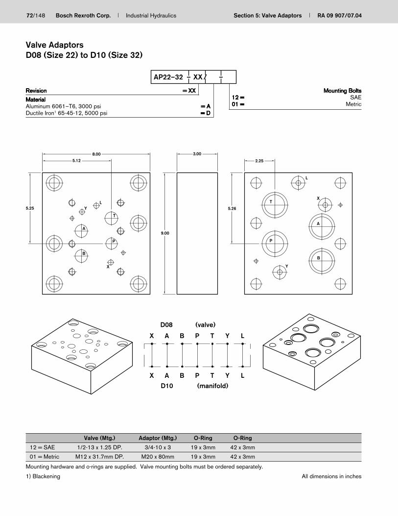
72/148 Bosch Rexroth Corp. Industrial Hydraulics Section 5: Valve Adaptors RA 09 907/07.04
RevisionRevisionRevisionRevisionRevision = XX= XX= XX= XX= XX
MaterialMaterialMaterialMaterialMaterialAluminum 6061–T6, 3000 psi = A= A= A= A= ADuctile Iron1 65-45-12, 5000 psi = D= D= D= D= D
Mounting BoltsMounting BoltsMounting BoltsMounting BoltsMounting Bolts12 =12 =12 =12 =12 = SAE01 =01 =01 =01 =01 = Metric
AP22–32 – XX / –
Valve (Mtg.) Adaptor (Mtg.) O-Ring O-Ring
12 = SAE 1/2-13 x 1.25 DP. 3/4-10 x 3 19 x 3mm 42 x 3mm
01 = Metric M12 x 31.7mm DP. M20 x 80mm 19 x 3mm 42 x 3mm
Mounting hardware and o-rings are supplied. Valve mounting bolts must be ordered separately.
1) Blackening All dimensions in inches
Valve AdaptorsD08 (Size 22) to D10 (Size 32)
2.25
5.26
YT
YT
L
L
5.128.00
D08
PBA
PB
D10
A
X
X
9.00
5.25
(valve)
(manifold)
3.00
YL
A
T
B
P
X
L
T
P
Y
X
A
B

The Drive & Control Company
ServiceAutomation
MobileHydraulics
IndustrialHydraulics
Electric Drivesand Controls
Linear Motion andAssembly Technologies Pneumatics
Section 6Pump Manifolds
RA 09 907/07.04
73

74/148 Bosch Rexroth Corp. Industrial Hydraulics Section 6: Pump Manifolds RA 09 907/07.04
Section 6 Index
Description Page
Pump Relief Block ................................................................................................................................................................................................................. 75
Pump Unloading Block ........................................................................................................................................................................................................ 78
Pump Manifold with Unloading Control ........................................................................................................................................................................... 80
Pump Manifold Pressure Relief Block with Unloading ................................................................................................................................................. 82
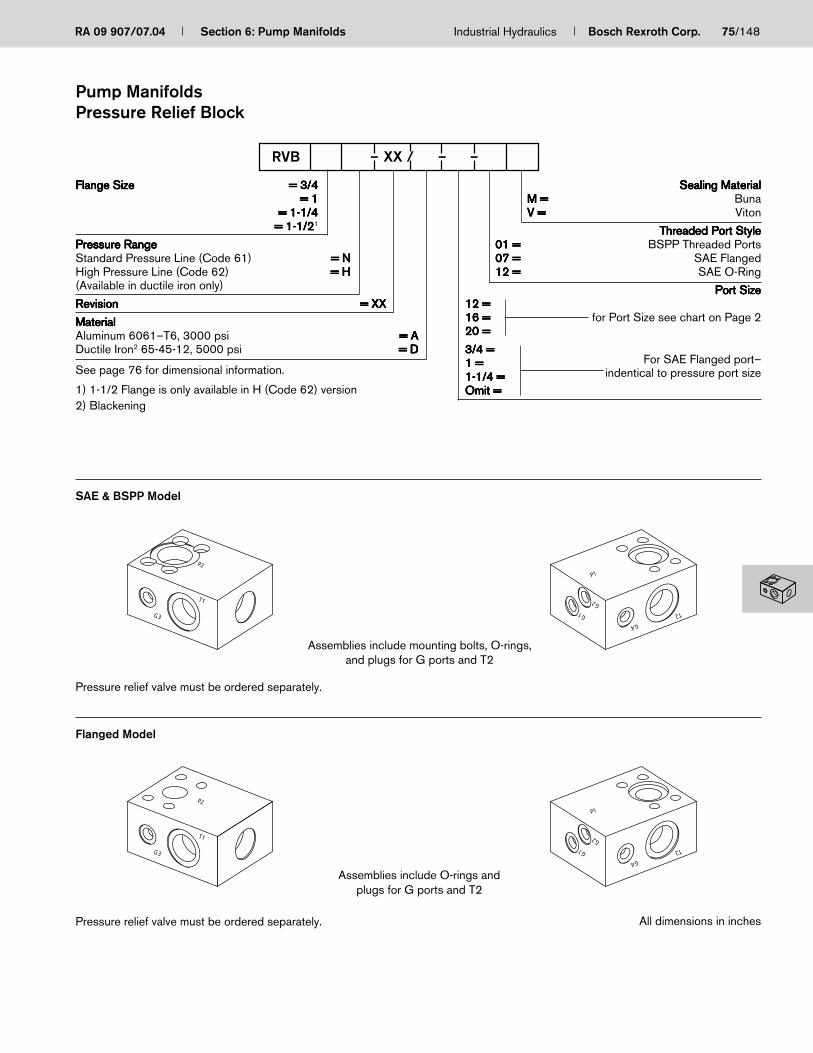
RA 09 907/07.04 Section 6: Pump Manifolds Industrial Hydraulics Bosch Rexroth Corp. 75/148
Flange SizeFlange SizeFlange SizeFlange SizeFlange Size = 3/4= 3/4= 3/4= 3/4= 3/4= 1= 1= 1= 1= 1
= 1-1/4= 1-1/4= 1-1/4= 1-1/4= 1-1/4= 1-1/2= 1-1/2= 1-1/2= 1-1/2= 1-1/21
Pressure RangePressure RangePressure RangePressure RangePressure RangeStandard Pressure Line (Code 61) = N= N= N= N= NHigh Pressure Line (Code 62) = H= H= H= H= H(Available in ductile iron only)
RevisionRevisionRevisionRevisionRevision = XX= XX= XX= XX= XX
MaterialMaterialMaterialMaterialMaterialAluminum 6061–T6, 3000 psi = A= A= A= A= ADuctile Iron2 65-45-12, 5000 psi = D= D= D= D= D
Sealing MaterialSealing MaterialSealing MaterialSealing MaterialSealing MaterialM =M =M =M =M = BunaV =V =V =V =V = Viton
Threaded Port StyleThreaded Port StyleThreaded Port StyleThreaded Port StyleThreaded Port Style01 =01 =01 =01 =01 = BSPP Threaded Ports07 =07 =07 =07 =07 = SAE Flanged12 =12 =12 =12 =12 = SAE O-Ring
Port SizePort SizePort SizePort SizePort Size12 =12 =12 =12 =12 =16 =16 =16 =16 =16 = for Port Size see chart on Page 220 =20 =20 =20 =20 =
3/4 =3/4 =3/4 =3/4 =3/4 =1 =1 =1 =1 =1 = For SAE Flanged port–1-1/4 =1-1/4 =1-1/4 =1-1/4 =1-1/4 = indentical to pressure port sizeOmit =Omit =Omit =Omit =Omit =
RVB – XX / – –
All dimensions in inches
Assemblies include O-rings andplugs for G ports and T2
G1
G2
G4
P1
T2
T1
G3
P2
See page 76 for dimensional information.
1) 1-1/2 Flange is only available in H (Code 62) version2) Blackening
Assemblies include mounting bolts, O-rings,and plugs for G ports and T2
SAE & BSPP Model
Flanged Model
Pressure relief valve must be ordered separately.
Pressure relief valve must be ordered separately.
G1
G2
G4
P1
T2
T1
G3
P2
Pump ManifoldsPressure Relief Block

76/148 Bosch Rexroth Corp. Industrial Hydraulics Section 6: Pump Manifolds RA 09 907/07.04
All dimensions in inches
1) Ports G3 and G4 available only on RVB1… for use with AA10VSO71 Series 312) Pressure Relief Valve must be ordered separately3) Dimension “M” shown for S Type adjustment4) 1-1/2 Flange is only available in H (Code 62) version
Dimension A B C D E F G H I J K L M3 N1 O1 Relief T1,T2 G1,G2,P2Valve2 G31,G41
RVB3/4N…12 4.50 3.00 2.25 0.88 1.50 1.13 1.50 2.80 1.75 1.00 1.80 1.20 7.18 — — DBDS10 SAE-8 SAE-4 SAE-12RVB3/4N…01 4.50 3.00 2.25 0.88 1.50 1.13 1.50 2.80 1.75 1.00 1.80 1.20 7.18 — — DBDS10 1/2” BSPP 1/4” BSPP 3/4” BSPPRVB3/4N…07 4.50 3.00 2.25 0.88 1.50 1.13 1.50 2.80 1.75 1.00 1.80 1.20 7.18 — — DBDS10 SAE-8 SAE-4 –
RVB1N…12 4.50 3.50 2.25 1.00 1.75 1.13 1.75 2.80 1.75 1.00 2.15 1.35 7.18 1.00 1.00 DBDS10 SAE-12 SAE-4 SAE-16RVB1N…01 4.50 4.00 2.25 1.00 2.00 1.13 2.0 2.80 1.75 1.00 2.40 1.60 7.18 1.00 1.00 DBDS10 3/4” BSPP 1/4” BSPP 1” BSPPRVB1N…07 4.50 3.50 2.25 1.00 1.75 1.13 1.75 2.80 1.75 1.00 2.15 1.35 7.18 1.00 1.00 DBDS10 SAE-12 SAE-4 –
RVB1-1/4N…12 5.00 3.50 2.25 1.25 1.75 1.13 1.75 3.30 1.75 1.00 2.15 1.35 7.68 — — DBDS10 SAE-12 SAE-4 SAE-20RVB1-1/4N…01 5.00 4.00 2.50 1.25 2.00 1.25 2.00 3.30 1.75 1.00 2.40 1.60 7.68 — — DBDS10 3/4” BSPP 1/4” BSPP 1-1/4” BSPPRVB1-1/4N…07 5.00 3.50 2.25 1.25 1.75 1.13 1.75 3.30 1.75 1.00 2.15 1.35 7.68 — — DBDS10 SAE-12 SAE-4 –
RVB3/4H…12 4.50 3.00 2.25 0.88 1.50 1.13 1.50 2.80 1.75 1.00 1.80 1.20 7.18 — — DBDS10 SAE-8 SAE-4 –RVB3/4H…01 4.50 3.50 2.25 0.88 1.75 1.13 1.75 2.80 1.75 1.00 2.15 1.45 7.18 — — DBDS10 1/2” BSPP 1/4” BSPP 3/4” BSPPRVB3/4H…07 4.50 3.00 2.25 0.88 1.50 1.13 1.50 2.80 1.75 1.00 1.80 1.20 7.18 — — DBDS10 SAE-8 SAE-4 –
RVB1H…12 4.50 3.00 2.25 1.00 1.75 1.13 1.75 2.80 1.75 1.00 2.15 1.35 7.18 1.00 1.00 DBDS10 SAE-12 SAE-4 SAE-16RVB1H…01 4.50 3.00 4.25 1.00 1.75 2.13 1.75 2.13 1.75 1.00 2.15 2.53 1.73 1.00 1.00 DBDS10 3/4” BSPP 1/4” BSPP 1” BSPPRVB1H…07 4.50 3.00 3.50 1.00 1.75 1.75 1.75 1.75 1.75 1.00 2.15 2.15 1.35 1.00 1.00 DBDS10 SAE-12 SAE-4 –
RVB1-1/4H…12 6.00 3.75 2.25 1.38 1.88 1.13 1.88 3.70 1.75 1.00 2.40 1.35 8.56 — — DBDS20 SAE-12 SAE-4 SAE-20RVB1-1/4H…01 6.00 3.75 2.25 1.38 1.88 1.13 1.88 3.70 1.75 1.00 2.40 1.35 8.56 — — DBDS20 3/4” BSPP 1/4” BSPP 1-1/4” BSPPRVB1-1/4H…07 6.00 3.75 2.25 1.38 1.88 1.13 1.88 3.70 1.75 1.00 2.40 1.35 8.56 — — DBDS20 SAE-12 SAE-4 –
RVB1-1/2H…07 7.00 5.00 2.75 1.38 2.50 1.38 2.50 4.64 2.00 1.25 2.90 2.10 10.27 — — DBDS30 SAE-24 SAE-4 –
F
G
C
H
N
M
A
H
D
F
B
E
I
J
F
O
K
L
P1
P1
T2G4
P2
T1G3
G1
G2
P2
T2P1
Schematic Symbol
T T1
G4
PG1
P2
G2
G3
Pump ManifoldsPressure Relief Block

RA 09 907/07.04 Section 6: Pump Manifolds Industrial Hydraulics Bosch Rexroth Corp. 77/148
All dimensions in inches
Orientation for Relief Blocks:RVB3/4...RVB1...RVB1-1/4...RVB1-1/2...
Orientation for AA10VSO71 Series 31 PumpRVB1…
Pump ManifoldsPressure Relief Block

78/148 Bosch Rexroth Corp. Industrial Hydraulics Section 6: Pump Manifolds RA 09 907/07.04
Logic A B C D E F G H I J K L M N O P Q R S
Size 25 8.20 6.45 4.90 5.50 2.04 4.75 1.59 5.50 3.01 3.01 4.08 2.04 1.70 4.55 0.35 6.10 0.35 12.75 14.00
Size 32 9.90 6.95 5.40 6.65 2.43 5.25 1.89 6.65 3.11 3.11 4.15 2.43 1.70 5.05 0.35 6.60 0.35 13.25 14.50
1) Blackening
Logic P, P1 T GA
Size 25 1-1/2” SAE 3000 PSI 1-1/2” SAE 3000 PSI SAE-6 (9/16-18UNF)(Code 61 Flange) (Code 61 Flange)
Size 25 1-1/2” SAE 6000 PSI 1-1/2” SAE 3000 PSI SAE-6 (9/16-18UNF)(Code 62 Flange) (Code 61 Flange)
Size 32 2” SAE 3000 PSI 2” SAE 3000 PSI SAE-6 (9/16-18UNF)(Code 61 Flange) (Code 61 Flange)
Size 32 2” SAE 6000 PSI 2” SAE 3000 PSI SAE-6 (9/16-18UNF)(Code 62 Flange) (Code 61 Flange)
Flange SizeFlange SizeFlange SizeFlange SizeFlange Size = 1-1/2= 1-1/2= 1-1/2= 1-1/2= 1-1/2= 2= 2= 2= 2= 2
Pressure RangePressure RangePressure RangePressure RangePressure RangeStandard Pressure Line (Code 61) = N= N= N= N= NHigh Pressure Line (Code 62) = H= H= H= H= H
Logic SizeLogic SizeLogic SizeLogic SizeLogic Size = 25= 25= 25= 25= 25= 32= 32= 32= 32= 32
RevisionRevisionRevisionRevisionRevision = XX= XX= XX= XX= XX
Port StylePort StylePort StylePort StylePort Style07 =07 =07 =07 =07 = SAE Flanged
MaterialMaterialMaterialMaterialMaterialD =D =D =D =D = Ductile Iron1 64-45-12, 5000 psi
C
DA
E
FB
G
I
H
M
LON
P
QK
J
T
P P
P
P1
GA
(4) 5/16-18 x .75 DP
RVBL – XX / –
All dimensions in inches
Pump ManifoldsUnloading
T
P1
P PGA
YY
XX
A B
P T
8
3
2
4 5
9
6 7
1
* Components must beordered separately

RA 09 907/07.04 Section 6: Pump Manifolds Industrial Hydraulics Bosch Rexroth Corp. 79/148
All dimensions in inches
Item Part No. Quantity Description
1 US00 811978 1 Manifold Block
2 RR00 003038 4 M6x100 SHCS D912-8.8 A3C
3 US00 800151 6 4HP50N-S Plug HOLHEX/SH
4 US00 800087 2 STR THRD EL90 4-4S SAE 37 PUA20
5 US00 800180 2 O-RG Sz 2-011 NBR 70SH WAS 0044
6 US00 800496 1 O-RG Sz 2-014 NBR 70SH WAS 0090
PSB – A10 – XX / D –
Item Part No. Quantity Description
7 RR00 008838 2 Setscrew M4X06-5.8 D427
8 US00 800693 4 SHCS 10-24X2 ASTM A574
9 RR00 0005527 1 Jet 1.0 M4X7 MS RN115.38
10 US00 802879 4 SHCS 10-24X1 1/4 ASTM A574
11 US00 802658 1 Socket Setscrew 1/4-20 UNC
Pump ManifoldSize 18 through 100, AA10VSO with Unloading Control
PumpPumpPumpPumpPump = A10= A10= A10= A10= A10
RevisionRevisionRevisionRevisionRevision = XX= XX= XX= XX= XX
MaterialMaterialMaterialMaterialMaterialDuctile Iron1 65-45-12, 5000 psi = D= D= D= D= D
DR-R =DR-R =DR-R =DR-R =DR-R =DR-L =DR-L =DR-L =DR-L =DR-L =DFR-R =DFR-R =DFR-R =DFR-R =DFR-R =DFR-L =DFR-L =DFR-L =DFR-L =DFR-L =
Threaded PortsThreaded PortsThreaded PortsThreaded PortsThreaded Ports12 =12 =12 =12 =12 = SAE1) Blackening
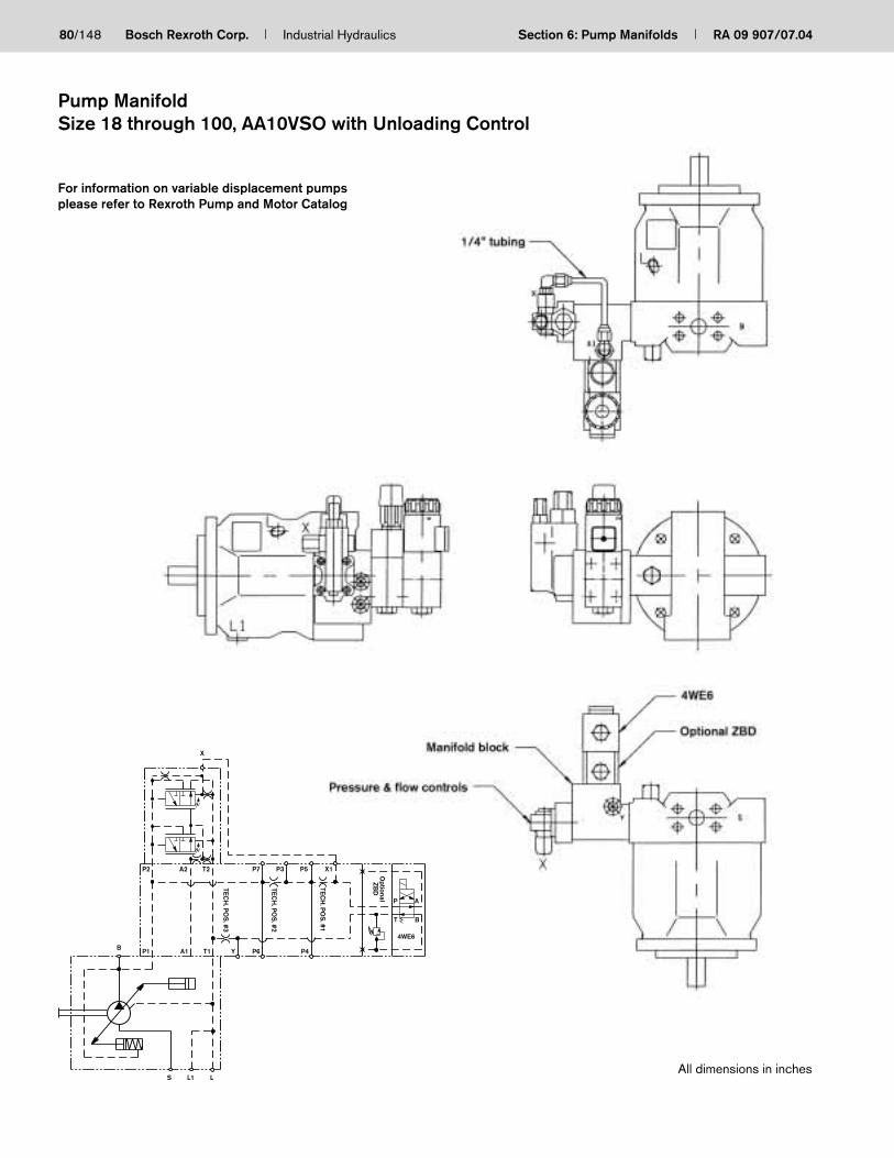
80/148 Bosch Rexroth Corp. Industrial Hydraulics Section 6: Pump Manifolds RA 09 907/07.04
For information on variable displacement pumpsplease refer to Rexroth Pump and Motor Catalog
All dimensions in inches
Pump ManifoldSize 18 through 100, AA10VSO with Unloading Control
TECH
. POS
. #1
TECH
. POS
. #2
TECH
. POS
. #3
T B
S L1
P1B A1
L
T1 Y P6 P4
X
P2 A2 T2 P7 X1P5
P
OptionalZB
D
A
P3
4WE6

RA 09 907/07.04 Section 6: Pump Manifolds Industrial Hydraulics Bosch Rexroth Corp. 81/148
Sealing MaterialSealing MaterialSealing MaterialSealing MaterialSealing MaterialM =M =M =M =M = BunaV =V =V =V =V = Viton
Threaded Port StyleThreaded Port StyleThreaded Port StyleThreaded Port StyleThreaded Port Style12 =12 =12 =12 =12 = SAE01 =01 =01 =01 =01 = BSPP0707070707 = = = = = SAE Flanged
Port Size (P2)Port Size (P2)Port Size (P2)Port Size (P2)Port Size (P2)12 =12 =12 =12 =12 =16 =16 =16 =16 =16 = SAE Ports20 =20 =20 =20 =20 =
3/4 =3/4 =3/4 =3/4 =3/4 =1 =1 =1 =1 =1 = BSPP Ports1-1/4 =1-1/4 =1-1/4 =1-1/4 =1-1/4 =
Omit =Omit =Omit =Omit =Omit = SAE Flanged Portidentical to press. port size (P1)
(Sandwich Plate Design)
All dimensions in inches
SAE & BSPP Model
Flange Size (P1)Flange Size (P1)Flange Size (P1)Flange Size (P1)Flange Size (P1) = 3/4= 3/4= 3/4= 3/4= 3/4= 1= 1= 1= 1= 1
= 1-1/4= 1-1/4= 1-1/4= 1-1/4= 1-1/4
Pressure RangePressure RangePressure RangePressure RangePressure RangeStandard Pressure Line (Code 61) = N= N= N= N= NHigh Pressure Line (Code 62) = H= H= H= H= H(Available in Ducile Iron Only)
RevisionRevisionRevisionRevisionRevision = XX= XX= XX= XX= XX
MaterialMaterialMaterialMaterialMaterialAluminum 6061-T6, 3000 psi = A= A= A= A= ADuctile Iron1 65-45-12, 5000 psi = D= D= D= D= D
RVBU – XX / – –
See pages 83for dimensional information.
1) Blackening
Flanged Model
Assemblies include mounting bolts,o-rings, and plugs for “G” ports and T2.
Assemblies include o-rings, and plugsfor “G” ports and T2.
Pressure relief valve and directional valve (“B” solenoid only). Must be ordered separately.
Pressure relief valve and directional valve (“B” solenoid only). Mounting flange, and bolts must be order separately.
Pump ManifoldPressure Relief Block with Unloading
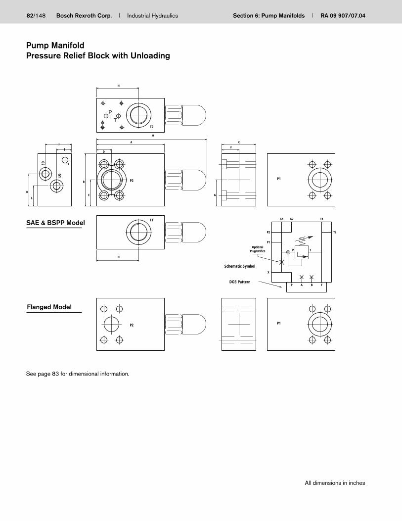
82/148 Bosch Rexroth Corp. Industrial Hydraulics Section 6: Pump Manifolds RA 09 907/07.04
All dimensions in inches
F
G
C
H
M
A
X
H
D
B
E
I
J
K
L
T2
DO3 Pattern
Plug/Orifice
G2G1
Schematic Symbol
P A TB
P1
P2 T2
T1
P T
X
Optional
P1
P1
P2
T1
G1
G2
SAE & BSPP Model
P2
Flanged Model
P
T
See page 83 for dimensional information.
Pump ManifoldPressure Relief Block with Unloading

RA 09 907/07.04 Section 6: Pump Manifolds Industrial Hydraulics Bosch Rexroth Corp. 83/148
Dimension A B C D E F G H I J K L M3 N1 O1 ReliefT1,T2
G1,G2,P2
Valve2 G31,G41
RVBU3/4N…12 SAE-8 SAE-4 SAE-12RVBU3/4N…01 4.50 4.00 3.00 0.88 1.50 1.13 1.50 2.80 1.75 1.00 1.80 1.20 7.18 — — DBDS10 1/2” BSPP 1/4” BSPP 3/4” BSPPRVBU3/4N…07 SAE-8 SAE-4 —
RVBU1N…12 4.50 1.75 1.75 2.15 1.35 SAE-12 SAE-4 SAE-16RVBU1N…01 4.75 5.00 2.25 1.00 2.00 1.13 2.00 2.80 1.75 1.00 2.40 1.60 7.18 1.00 1.00 DBDS10 3/4” BSPP 1/4” BSPP 1” BSPPRVBU1N…07 4.50 1.75 1.75 2.15 1.35 SAE-12 SAE-4 —
RVBU1-1/4N…12 4.50 3.00 1.75 1.13 1.75 2.15 1.35 SAE-12 SAE-4 SAE-20RVBU1-1/4N…01 5.00 5.00 3.25 1.25 2.00 1.25 2.00 3.30 1.75 1.00 2.40 1.60 7.68 — — DBDS10 3/4” BSPP 1/4” BSPP 1-1/4” BSPPRVBU1-1/4N…07 4.50 3.00 1.75 1.13 1.75 2.15 1.35 SAE-12 SAE-4 —
RVBU3/4H…12 4.00 1.50 1.50 1.80 1.20 SAE-8 SAE-4 —RVBU3/4H…01 4.50 4.50 2.25 0.88 1.75 1.13 1.75 2.80 1.75 1.00 2.15 1.45 7.18 — — DBDS10 1/2” BSPP 1/4” BSPP 3/4” BSPPRVBU3/4H…07 4.00 1.50 1.50 1.80 1.20 SAE-8 SAE-4 —
RVBU1H…12 4.50 1.75 1.75 2.15 1.35 SAE-12 SAE-4 SAE-16RVBU1H…01 4.50 5.25 3.00 1.00 2.13 1.13 2.13 2.13 1.75 1.00 2.53 1.73 7.18 1.00 1.00 DBDS10 3/4” BSPP 1/4” BSPP 1” BSPPRVBU1H…07 4.5 1.75 1.75 2.15 1.35 SAE-12 SAE-4 —
RVBU1-1/4H…12 SAE-12 SAE-4 SAE-20RVBU1-1/4H…01 6.00 4.75 2.25 1.38 1.88 1.13 1.88 3.70 1.75 1.00 2.40 1.35 8.56 — — DBDS20 3/4” BSPP 1/4” BSPP 1-1/4” BSPPRVBU1-1/4H…07 SAE-12 SAE-4 —
1) Ports G3 and G4 available only on RVB1... for use with AA10VSO71 Series 312) Pressure relief valve must be ordered separately3) Dimension “M” shown for S type adjustmentSee page 82 (MS-06-0400, page 4 of 4) for mounting orientations.
All dimensions in inches
Pump ManifoldPressure Relief Block with Unloading

84/148 Bosch Rexroth Corp. Industrial Hydraulics Section 6: Pump Manifolds RA 09 907/07.04
S
P2
S
G1 & G2
X
L
L
X
X
L
L1
XL
L1
P2
T1
G2
G1
X
T1
P2
Orientation for AA10VSO71 Series 31Pump RVBU1...
Orienation for relief blocks:RVBU3/4...RVBU1...RVBU1-1/4...
Directional Valve (“B” solenoid only)Directional Valve (“B” solenoid only)Directional Valve (“B” solenoid only)Directional Valve (“B” solenoid only)Directional Valve (“B” solenoid only)
Pump ManifoldPressure Relief Block with Unloading

The Drive & Control Company
ServiceAutomation
MobileHydraulics
IndustrialHydraulics
Electric Drivesand Controls
Linear Motion andAssembly Technologies Pneumatics
Section 7Logic Manifolds
RA 09 907/07.04
85
Logic Manifold Features
– Sizes 16 to 63 available
– One design to provide various control functionsby orifice/plug provisions
– Provided configuration per chosen model code

86/148 Bosch Rexroth Corp. Industrial Hydraulics Section 7: Logic Manifolds RA 09 907/07.04
Section 7 Index
Description Page
Logic Control Block .............................................................................................................................................................................................................. 87

RA 09 907/07.04 Section 7: Logic Manifolds Industrial Hydraulics Bosch Rexroth Corp. 87/148
J
I
H
C
G
N
M
O
P
K
LPos. 2
Pos. 1
Pos. 3
Pos. 4
Port 2
Pos. 6(Internal)
Port 1
Port 3
Pos. 5(Internal)
Pos. 7(Internal)
A
B
For Tap Mtg.
(See Chart Below)
Note: Locating pin holes allow 90°rotations of cover forapplications listed on Page 2
Note: X, Y, Z1, Z2 pilot holes aretapped for orifice or plug(4 places)
Note: Flange pattern rotated 90°on sizes 25, 32, 40, 50, 633000 PSI logic manifolds
F
B
E
DA
Q
Nominal SizeNominal SizeNominal SizeNominal SizeNominal Size = 16–63= 16–63= 16–63= 16–63= 16–63
Pressure RangePressure RangePressure RangePressure RangePressure RangeNormal (Code 61) = N= N= N= N= NHigh (Code 62) = H= H= H= H= H
RevisionRevisionRevisionRevisionRevision = XX= XX= XX= XX= XX
MaterialMaterialMaterialMaterialMaterialDuctile Iron1 65-45-12, 5000 psi = D= D= D= D= D
M=M=M=M=M= Metric
Omit =Omit =Omit =Omit =Omit = StandardA-Z =A-Z =A-Z =A-Z =A-Z = See Page 3 for Configuration
07 =07 =07 =07 =07 = SAE Flange
1 =1 =1 =1 =1 = Number of Cartridge per Block
LCB – XX / – M
Size Pos. 1, 2, 3, 4 Pos. 5, 6, 7
16 10-24UNC 1/16-27NPT
25 1/4-20UNC 1/16-27NPT
32 1/16-27NPT 1/16-27NPT
40 1/8-27NPT 1/8-27NPT
50 1/8-27NPT 1/8-27NPT
63 1/8-27NPT 1/8-27NPT
Note:Note:Note:Note:Note: Standard Logic Manifold comes withplugs for Ports 1-3, Positions 1-4, andPosition 7 at the surface. Plugs for Positions5-7 (internal) and all orifices must be orderedseparately.
1)Blackening All dimensions in inches
Logic ManifoldsLogic Control Block

88/148 Bosch Rexroth Corp. Industrial Hydraulics Section 7: Logic Manifolds RA 09 907/07.04
Size PSI FlgTap Port
A B C D E F G H I J K L M N O P QMtg. 1-2-3
16 N 1” 3/8- SAE-4 3.80 3.30 3.40 3.30 2.10 2.70 1.70 1.18 1.70 2.10 2.70 2.10 — 1.60 0.50 2.90 —5000 16x0.75
16 H 1” 3/8- SAE-4 3.80 3.30 3.40 3.30 2.10 2.70 1.70 1.18 1.70 2.10 2.70 2.10 — 1.60 0.50 2.90 —6000 16x0.75
25 N 1.25” 3/8- SAE-4 3.90 3.70 3.70 3.45 2.22 3.20 1.85 1.58 1.85 2.22 3.20 2.22 — 2.00 0.47 3.22 —4000 16x0.75
25 H 1.25” 7/16- SAE-4 4.50 4.20 3.80 3.95 2.70 3.50 1.90 1.55 1.90 2.70 3.50 2.70 — 2.00 0.50 3.30 —6000 14x0.80
32 N 1.50” 1/2- SAE-4 4.50 4.50 4.20 4.00 2.48 3.80 2.10 1.90 2.10 2.48 3.80 2.48 — 2.50 0.47 3.72 —3000 13x0.75
32 H 1.50” 1/2- SAE-4 5.40 4.80 4.50 4.90 3.30 3.80 2.25 1.90 2.25 3.30 3.80 3.30 — 2.50 0.50 4.00 4.156000 13x0.75
40 N 2.00” 5/8- SAE-6 5.40 5.30 5.00 4.80 2.87 4.60 2.50 2.32 2.50 2.87 4.60 2.87 — 3.00 0.62 4.37 —3000 11x1.0
40 H 2.00” 5/8- SAE-6 6.40 6.30 5.40 5.75 3.80 5.00 2.70 2.35 2.70 3.80 5.00 3.80 — 3.40 0.50 4.60 5.506000 11x0.95
50 N 2.50” 3/8- SAE-6 6.20 6.20 5.70 5.50 3.23 4.80 2.85 2.58 2.85 3.23 5.40 3.23 5.75 3.00 0.53 5.15 —2500 16x0.75*
50 H 2.50” 3/8- SAE-6 6.80 6.90 7.00 6.25 4.00 5.50 3.50 2.60 3.50 4.00 5.50 4.00 6.00 3.00 0.60 0.60 4.502000 16x0.70*
63 N 3.00” 7/16- SAE-6 7.70 8.70 7.40 7.00 4.05 7.00 3.70 3.39 3.70 4.05 7.00 4.05 8.13 3.75 0.51 6.89 —2000 14x1.0
63 H 3.00” 7/16- SAE-6 9.10 8.30 8.50 8.35 5.40 7.00 4.25 3.50 4.25 5.40 7.00 5.40 7.50 3.50 0.50 7.70 6.502000 14x0.70
Logic ManifoldsLogic Control Block
*LCB50 logic cover mounting taps are machined for UNC covers only, consult factory if using covers with metric mounting.

RA 09 907/07.04 Section 7: Logic Manifolds Industrial Hydraulics Bosch Rexroth Corp. 89/148
Port 1
B
A
Pos. 1
Pos. 5
Pos. 2
Port 2
Port 3
Pos. 7
Pos. 6
Pos. 3 Pos. 4
Note: Ports not being usedmust be plugged
O = Open X = Plugged
Configuration X Y Z1 Z2 Pos. 1 Pos. 2 Pos. 3 Pos. 4 Pos. 5 Pos. 6 Pos. 7
Standard — — — — X X X X O O O
A Ext. Port 1 Ext. Port 2 — — O X O X X X X
B Int. “A” Side Ext. Port 2 — — O X O X O X X
C Int. “B” Side Ext. Port 3 — — X O X O X X X
D Ext. Port 1 Int. “A” Side — — O X O X X O X
E Int. “B” Side Int. “A” Side — — X O X O X X O
F Ext. Port 3 Int. “B” Side — — X O X O X X X
G Int. “A” Side Int. “B” Side — — X O X O X X O
H Ext. Port 2 Ext. Port 1 Int. “A” Side — O X O O X X O
J Ext. Port 1 Ext. Port 2 Int. “B” Side — O O O X X X X
K Int. “A” Side Ext. Port 1 Ext. Port 3 — O X O O X O X
L Int. “B” Side Ext. Port 5 Ext. Port 2 — X O O O X X X
M Int. “A” Side Ext. Port 2 Int. “B” Side — O O O X O X X
N Int. “B” Side Ext. Port 3 Int. “A” Side — X O O O X O X
O Int. “B” Side — Int. “A” Side Ext. Port 1 O O O X X O X
P Int. “A” Side — Int. “B” Side Ext. Port3 O O X O O X X
S Int. “A” Side Ext. Port 1 Ext. Port 3 Int. “B” Side O O O O X O X
T Int. “B” Side Ext. Port 3 Ext. Port 2 Int. “A” Side O O O O O X X
U Int. “A” Side Ext. Port 2 Int. “B” Side Ext. Port 3 O O O O O X X
V Int. “B” Side Ext. Port 3 Int. “A” Side Ext. Port 1 O O O O X O X
W Int. “B” Side — — — X O X X X X X
X Ext. Port 1 — — — O X X X X X X
Y Int. “B” Side — — — X O X X X X O
Illustration of “standard“ plug configuration
Logic ManifoldsLogic Control Block

90/148 Bosch Rexroth Corp. Industrial Hydraulics Section 7: Logic Manifolds RA 09 907/07.04

The Drive & Control Company
ServiceAutomation
MobileHydraulics
IndustrialHydraulics
Electric Drivesand Controls
Linear Motion andAssembly Technologies Pneumatics
Section 8Compact Bodies
RA 09 907/07.04
91
Compact Bodies Features
– Aluminum and ductile iron
– SAE, BSPP, or NPT porting

92/148 Bosch Rexroth Corp. Industrial Hydraulics Section 8: Compact Bodies RA 09 907/07.04
Section 8 Index
Description Page
T-8A Cavity ............................................................................................................................................................................................................................. 93
T-11A Cavity ........................................................................................................................................................................................................................... 94
T-13A Cavity ........................................................................................................................................................................................................................... 95
T-31A Cavity ........................................................................................................................................................................................................................... 96
T-162A Cavity ........................................................................................................................................................................................................................ 97

RA 09 907/07.04 Section 8: Compact Bodies Industrial Hydraulics Bosch Rexroth Corp. 93/148
Compact BodiesT-8A Cavity
Dimension A B C D E F G H J K L M
CB1… 2.25 1.95 1.95 0.95 0.45 0.38 1.88 1.58 1.00 1.13 0.95 1.13
Mounting hardware is NOT supplied.
1) Blackening
1 & 2 PortsPort type 12 05 01 Aluminum Ductile
CB1L-1X/...7/16-20
— — 0.8 2.2SAE-4
CB1N-1X/...9/16-18
NPT 1/4” G (BSP) 1/4” 0.8 2.2SAE-6
All dimensions in inches
FlowFlowFlowFlowFlowLow = L= L= L= L= LNormal = N= N= N= N= N
RevisionRevisionRevisionRevisionRevision = XX= XX= XX= XX= XX
PortsPortsPortsPortsPorts12 =12 =12 =12 =12 = SAE Threaded Ports05 =05 =05 =05 =05 = NPT Threaded Ports01 =01 =01 =01 =01 = BSPP Threaded Ports
MaterialMaterialMaterialMaterialMaterialA =A =A =A =A = Aluminum 6061–T6, 3000 psiD =D =D =D =D = Ductile Iron1 65-45-12, 5000 psi
CB1 – XX / –
T-8A CAVITYK
L
A
CB
1N
-1X
RE
XR
OT
H
/A
-12
G
FD
C
2
E
HB
M
1
J
(2) 11/32″ DIA. DRILL THRU (MTG.)
1
2
1

94/148 Bosch Rexroth Corp. Industrial Hydraulics Section 8: Compact Bodies RA 09 907/07.04
Compact BodiesT-11A Cavity
Dimension A B C D E F G H J K L M N P
CB2… 2.75 2.95 1.95 1.00 1.41 1.00 0.56 1.38 0.38 2.57 0.44 1.38 1.00 1.00
Mounting hardware is NOT supplied.
1) Blackening
1 & 2 Ports 3 PortPort type 12 05 01 12 05 01 Aluminum Ductile
CB2L-1X/...7/16-20
— —7/16-20 — —
1.6 4.2SAE-4 SAE-4
CB2N-1X/...9/16-18
NPT 1/4” G (BSP) 1/4”9/16-18
NPT 1/4” G (BSP) 1/4” 1.6 4.2SAE-6 SAE-6
CB2H-1X/...3/4-16
NPT 3/8” G (BSP) 3/8”3/4-16
NPT 3/8” G (BSP) 3/8” 1.6 4.2SAE-8 SAE-8
CB2X-1X/...7/8-14
NPT 1/2” G (BSP) 1/2”3/4-16
NPT 1/2” G (BSP) 1/2” 1.6 4.2SAE-10 SAE-8
All dimensions in inches
FlowFlowFlowFlowFlowLow = L= L= L= L= LNormal = N= N= N= N= NHigh = H= H= H= H= HExtra High = X= X= X= X= X
RevisionRevisionRevisionRevisionRevision = XX= XX= XX= XX= XX
PortsPortsPortsPortsPorts12 =12 =12 =12 =12 = SAE Threaded Ports05 =05 =05 =05 =05 = NPT Threaded Ports01 =01 =01 =01 =01 = BSPP Threaded Ports
MaterialMaterialMaterialMaterialMaterialA =A =A =A =A = Aluminum 6061–T6, 3000 psiD =D =D =D =D = Ductile Iron1 65-45-12, 5000 psi
CB2 – XX / –
G
T-11A CAVITY
N
M
RE
XR
OT
HC
B2
N-1
X/
A-1
22
(2) 11/32″ DIA. DRILL THRU (MTG.)
BK
L
A
J
E
C
D
1P
HREXROTH
CB2N-1X/A-12
F
3
REXROTHCB2N-1X/A-12
3
2
1
31
2

RA 09 907/07.04 Section 8: Compact Bodies Industrial Hydraulics Bosch Rexroth Corp. 95/148
Compact BodiesT-13A Cavity
Dimension A B C D E F G H J K L
CB3… 1.95 2.25 1.95 0.95 0.75 0.38 1.88 1.23 1.23 0.95 1.00
Mounting hardware is NOT supplied.
1) Blackening
1 & 2 PortsPort type 12 05 01 Aluminum Ductile
CB3L-1X/...7/16-20
— — 0.8 2.2SAE-4
CB3N-1X/...9/16-18
NPT 1/4” G (BSP) 1/4” 0.8 2.2SAE-6
CB3H-1X/...3/4-16
NPT 3/8” G (BSP) 3/8” 0.8 2.2SAE-8
All dimensions in inches
FlowFlowFlowFlowFlowLow = L= L= L= L= LNormal = N= N= N= N= NHigh = H= H= H= H= H
RevisionRevisionRevisionRevisionRevision = XX= XX= XX= XX= XX
PortsPortsPortsPortsPorts12 =12 =12 =12 =12 = SAE Threaded Ports05 =05 =05 =05 =05 = NPT Threaded Ports01 =01 =01 =01 =01 = BSPP Threaded Ports
MaterialMaterialMaterialMaterialMaterialA =A =A =A =A = Aluminum 6061–T6, 3000 psiD =D =D =D =D = Ductile Iron1 65-45-12, 5000 psi
CB3 – XX / –
T-13A CAVITY
K
J
A
CB
3N
-1X
/A
-12
RE
XR
OT
H
B
F
G
C
2
D
E
H
1
L
(1) 11/32″ DIA. DRILL THRU (MTG.)
/A-12CB3N-1X
REXROTH
1
2
12
REXROTH /A-12CB3N-1X

96/148 Bosch Rexroth Corp. Industrial Hydraulics Section 8: Compact Bodies RA 09 907/07.04
Compact BodiesT-31A Cavity
1, 2, 3, 4 PortsPort type 12 05 01 Aluminum Ductile
CB4N-1X/...9/16-18
NPT 1/4” G (BSP) 1/4” 2.6 7.0SAE-6
CB4H-1X/...3/4-16
NPT 3/8” G (BSP) 3/8” 2.6 7.0SAE-8
CB4H-1X/...7/8-14
NPT 1/2” G (BSP) 1/2” 2.6 7.0SAE-10
FlowFlowFlowFlowFlowNormal = N= N= N= N= NHigh = H= H= H= H= HExtra High = X= X= X= X= X
RevisionRevisionRevisionRevisionRevision = XX= XX= XX= XX= XX
PortsPortsPortsPortsPorts12 =12 =12 =12 =12 = SAE Threaded Ports05 =05 =05 =05 =05 = NPT Threaded Ports01 =01 =01 =01 =01 = BSPP Threaded Ports
MaterialMaterialMaterialMaterialMaterialA =A =A =A =A = Aluminum 6061–T6, 3000 psiD =D =D =D =D = Ductile Iron1 65-45-12, 5000 psi
CB4 – XX / –
Dimension A B C D E F G H J K L M N P
CB4… 2.75 4.95 1.95 1.00 1.81 4.30 1.00 0.88 0.38 0.83 2.95 1.38 1.00 2.72
Mounting hardware is NOT supplied.
1) Blackening All dimensions in inches
T-31A CAVITYM
N
4
RE
XR
OT
H
3
J
K
A
GD
E
C
21
(2) 11/32″ DIA. DRILL THRU (MTG.)
CB4N-1X/A-12
REXROTH
CB
4N
-1X
/A
-12F
L
B
CB4N-1X/A-12
H
P
REXROTH
1
3
2
4
3
2
4
1

RA 09 907/07.04 Section 8: Compact Bodies Industrial Hydraulics Bosch Rexroth Corp. 97/148
Compact BodiesT-162A Cavity
Dimension A B C D E F G H J K L
CB5… 1.95 2.25 1.95 0.95 0.87 0.38 1.88 1.25 1.25 0.95 1.00
Mounting hardware is NOT supplied.
1) Blackening
1 & 2 PortsPort type 12 05 01 Aluminum Ductile
CB5L-1X/...7/16-20
— — 0.8 2.2SAE-4
CB5N-1X/...9/16-18
NPT 1/4” G (BSP) 1/4” 0.8 2.2SAE-6
CB5H-1X/...3/4-16
NPT 3/8” G (BSP) 3/8” 0.8 2.2SAE-8
All dimensions in inches
FlowFlowFlowFlowFlowLow = L= L= L= L= LNormal = N= N= N= N= NHigh = H= H= H= H= H
RevisionRevisionRevisionRevisionRevision = XX= XX= XX= XX= XX
PortsPortsPortsPortsPorts12 =12 =12 =12 =12 = SAE Threaded Ports05 =05 =05 =05 =05 = NPT Threaded Ports01 =01 =01 =01 =01 = BSPP Threaded Ports
MaterialMaterialMaterialMaterialMaterialA =A =A =A =A = Aluminum 6061–T6, 3000 psiD =D =D =D =D = Ductile Iron1 65-45-12, 5000 psi
CB5 – XX / –
J
K
T-162A CAVITY
/A
-12
CB
5N
-1X
F
G
RE
XR
OT
H
1
L
H
(1) 11/32″ DIA. DRILL THRU (MTG.)
A
2
E
D
C
B
1
2
/A-12CB5N-1X
REXROTH
REXROTH /A-12CB5N-1X
12

98/148 Bosch Rexroth Corp. Industrial Hydraulics Section 8: Compact Bodies RA 09 907/07.04

The Drive & Control Company
ServiceAutomation
MobileHydraulics
IndustrialHydraulics
Electric Drivesand Controls
Linear Motion andAssembly Technologies Pneumatics
Section 9Compact Sandwich
RA 09 907/07.04
99
Compact Sandwich Features
– Aluminum and ductile iron
– SAE, BSPP, or NPT porting

100/148 Bosch Rexroth Corp. Industrial Hydraulics Section 9: Compact Sandwich RA 09 907/07.04
Section 9 Index
Description Page
D03 with T-162A Cavity ....................................................................................................................................................................................................101
D03 with T-13A Cavity .......................................................................................................................................................................................................102

RA 09 907/07.04 Section 9: Compact Sandwich Industrial Hydraulics Bosch Rexroth Corp. 101/148
Compact SandwichT-162A Cavity, D03 (Size 6)
CircuitCircuitCircuitCircuitCircuitP to T = 1= 1= 1= 1= 1A to T = 2= 2= 2= 2= 2B to T = 3= 3= 3= 3= 3A, B to T = 4= 4= 4= 4= 4
RevisionRevisionRevisionRevisionRevision = XX= XX= XX= XX= XX
PortsPortsPortsPortsPorts12 =12 =12 =12 =12 = SAE
MaterialMaterialMaterialMaterialMaterialA =A =A =A =A = Aluminum 6061–T6, 3000 psiD =D =D =D =D = Ductile Iron1 65-45-12, 5000 psi
CS1 – XX / –
J
H
AC
FE
B
D
G
T1A1P1 B1
TAP B
T1A1P1 B1
TAP B
T1A1
A T
P1
P B
B1T1
T
A1
A
B1
B
P1
P
T-162AT-162A T-162A
T-162AT-162A
2
3 4
1
Dimension A B C D E F G H J
CS21… 1.75 3.75 1.75 2.36 0.47 0.55 0.88 — —
CS22… 1.75 3.25 1.75 1.14 0.47 — — 0.55 0.88
CS23… 1.75 3.25 1.75 2.11 0.47 0.55 0.88 — —
CS24… 1.75 4.22 1.75 2.11 0.47 0.55 0.88 0.55 0.88
Mounting hardware is NOT supplied.
1) Blackening All dimensions in inches

102/148 Bosch Rexroth Corp. Industrial Hydraulics Section 9: Compact Sandwich RA 09 907/07.04
Compact SandwichT-13A Cavity, D03 (Size 6)
CircuitCircuitCircuitCircuitCircuitP to T = 1= 1= 1= 1= 1A to T = 2= 2= 2= 2= 2B to T = 3= 3= 3= 3= 3A, B to T = 4= 4= 4= 4= 4
RevisionRevisionRevisionRevisionRevision = XX= XX= XX= XX= XX
PortsPortsPortsPortsPorts12 =12 =12 =12 =12 = SAE
MaterialMaterialMaterialMaterialMaterialA =A =A =A =A = Aluminum 6061–T6, 3000 psiD =D =D =D =D = Ductile Iron1 65-45-12, 5000 psi
CS2 – XX / –
Dimension A B C D E F G H J
CS21… 2.00 3.87 1.75 2.56 0.47 1.19 0.88 — —
CS22… 2.00 3.13 1.75 1.19 0.47 — — 1.19 0.88
CS23… 2.00 3.13 1.75 1.94 0.47 1.19 0.88 — —
CS24… 2.00 3.87 1.75 1.94 0.47 1.19 0.88 1.19 0.88
Mounting hardware is NOT supplied.
1) Blackening All dimensions in inches
H
J
B
A
G
FE
D
C
T1A1P1 B1
TAP B
T1A1P1 B1
TAP B
T1A1
A T
P1
P B
B1T1
T
A1
A
B1
B
P1
P
T-13AT-13A T-13A
T-13AT-13A
2
3 4
1
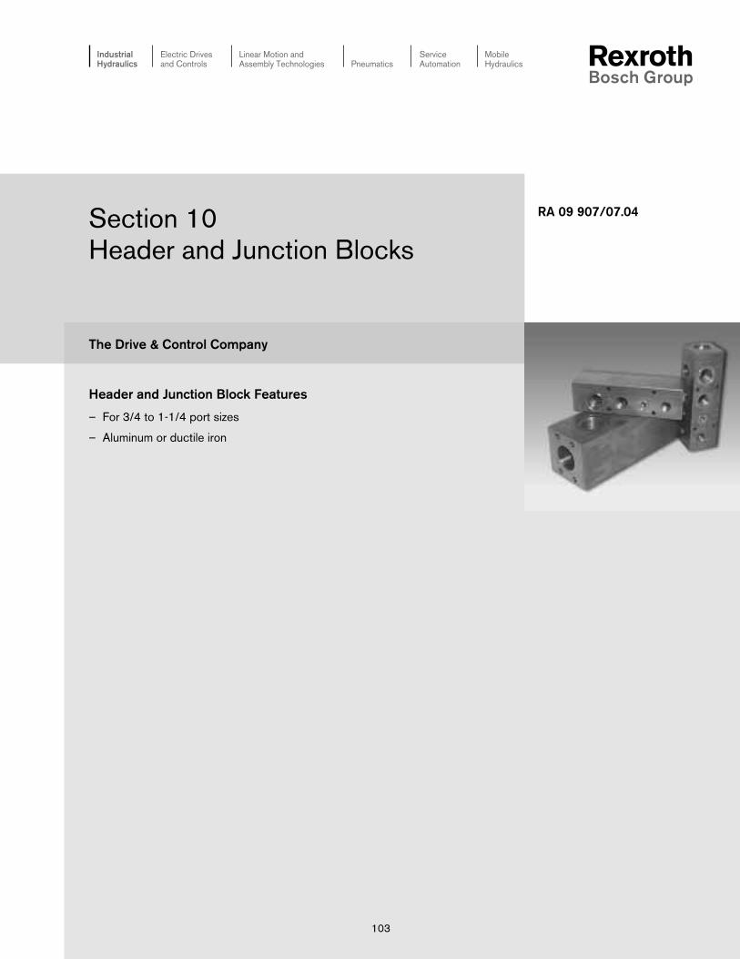
The Drive & Control Company
ServiceAutomation
MobileHydraulics
IndustrialHydraulics
Electric Drivesand Controls
Linear Motion andAssembly Technologies Pneumatics
Section 10Header and Junction Blocks
RA 09 907/07.04
103
Header and Junction Block Features
– For 3/4 to 1-1/4 port sizes
– Aluminum or ductile iron

104/148 Bosch Rexroth Corp. Industrial Hydraulics Section 10: Header and Junction Blocks RA 09 907/07.04
Section 10 Index
Description Page
Header Blocks .....................................................................................................................................................................................................................105
Junction Blocks ....................................................................................................................................................................................................................107

RA 09 907/07.04 Section 10: Header and Junction Blocks Industrial Hydraulics Bosch Rexroth Corp. 105/148
Port SizePort SizePort SizePort SizePort Size3/4“ BSPP = 3/4= 3/4= 3/4= 3/4= 3/41“ BSPP = 1= 1= 1= 1= 11-1/4“ BSPP = 1-1/4= 1-1/4= 1-1/4= 1-1/4= 1-1/412 SAE = 12= 12= 12= 12= 1216 SAE = 16= 16= 16= 16= 1620 SAE = 20= 20= 20= 20= 20
RevisionRevisionRevisionRevisionRevision = XX= XX= XX= XX= XX
Degree Design 0, 90, 180Degree Design 0, 90, 180Degree Design 0, 90, 180Degree Design 0, 90, 180Degree Design 0, 90, 180
Port StylePort StylePort StylePort StylePort Style01 =01 =01 =01 =01 = BSPP12 =12 =12 =12 =12 = SAE
2–6 =2–6 =2–6 =2–6 =2–6 = Number of Stations
MaterialMaterialMaterialMaterialMaterialA =A =A =A =A = Aluminum 6061–T6, 3000 psiD =D =D =D =D = Ductile Iron1 65-45-1, 5000 psi
HB – XX / – /
All dimensions in inches
Outlet Ports
Supply PortSupply Port
L DIA - M Places
A
AC
BE TYPD
CC
C
E TYPD
G
FK
JH
KJH
G
F
See page 105 for dimensional information
Mounting Bolts Supply Ports Outlet Ports
HB3/4-1X/… M8-1.25 x (80) LG SHCS 1” BSPP 3/4” BSPP
HB1-1X/… M10-1.5 x (90) LG SHCS 1-1/4” BSPP 1” BSPP
HB1-1/4-1X/… M12-1.75 x (120) LG SHCS 1-1/2” BSPP 1-1/4” BSPP
HB12-1X/… 5/16-18 x 3.00 LG SHCS SAE-16 SAE-12
HB16-1X/… 3/8-16 x 3.50 LG SHCS SAE-20 SAE-16
HB20-1X/… 1/2-14 x 4.50 LG SHCS SAE-24 SAE-20
Mounting Hardware Included
1) Blackening
Header Blocks
0° Design
90° Design
180° Design

106/148 Bosch Rexroth Corp. Industrial Hydraulics Section 10: Header and Junction Blocks RA 09 907/07.04
Dimension A B C D E F G H J K L M
HB3/4-1X/*2-01 2.50 6.88 1.25 1.81 3.25 0.28 1.94 0.38 – 6.13 0.34 4.00
HB3/4-1X/*3-01 2.50 10.13 1.25 1.81 3.25 0.28 1.94 0.38 – 9.38 0.34 4.00
HB3/4-1X/*4-01 2.50 13.38 1.25 1.81 3.25 0.28 1.94 0.38 – 12.63 0.34 4.00
HB3/4-1X/*5-01 2.50 16.63 1.25 1.81 3.25 0.28 1.94 0.38 – 15.88 0.34 4.00
HB3/4-1X/*6-01 2.50 19.88 1.25 1.81 3.25 0.28 1.94 0.38 9.56 19.13 0.34 6.00
HB1-1X/*2-01 3.00 7.75 1.50 2.00 3.75 0.34 2.31 0.38 – 7.00 0.41 4.00
HB1-1X/*3-01 3.00 11.50 1.50 2.00 3.75 0.34 2.31 0.38 – 10.75 0.41 4.00
HB1-1X/*4-01 3.00 15.25 1.50 2.00 3.75 0.34 2.31 0.38 – 14.50 0.41 4.00
HB1-1X/*5-01 3.00 19.00 1.50 2.00 3.75 0.34 2.31 0.38 – 18.25 0.41 4.00
HB1-1X/*6-01 3.00 22.75 1.50 2.00 3.75 0.34 2.31 0.38 11.00 22.00 0.41 6.00
HB1-1/4-1X/*2-01 3.50 8.50 1.75 2.25 4.00 0.41 2.69 0.50 – 7.50 0.53 4.00
HB1-1/4-1X/*3-01 3.50 12.50 1.75 2.25 4.00 0.41 2.69 0.50 – 11.50 0.53 4.00
HB1-1/4-1X/*4-01 3.50 16.50 1.75 2.25 4.00 0.41 2.69 0.50 – 15.50 0.53 4.00
HB1-1/4-1X/*5-01 3.50 20.50 1.75 2.25 4.00 0.41 2.69 0.50 – 19.50 0.53 4.00
HB1-1/4-1X/*6-01 3.50 24.50 1.75 2.25 4.00 0.41 2.69 0.50 11.75 23.50 0.53 6.00
HB12-1X/*2-12 2.50 6.88 1.25 1.81 3.25 0.28 1.94 0.38 – 6.13 0.34 4.00
HB12-1X/*3-12 2.50 10.13 1.25 1.81 3.25 0.28 1.94 0.38 – 9.38 0.34 4.00
HB12-1X/*4-12 2.50 13.38 1.25 1.81 3.25 0.28 1.94 0.38 – 12.63 0.34 4.00
HB12-1X/*5-12 2.50 16.63 1.25 1.81 3.25 0.28 1.94 0.38 – 15.88 0.34 4.00
HB12-1X/*6-12 2.50 19.88 1.25 1.81 3.25 0.28 1.94 0.38 9.56 19.13 0.34 6.00
HB16-1X/*2-12 3.00 7.75 1.50 2.00 3.75 0.34 2.31 0.38 – 7.00 0.41 4.00
HB16-1X/*3-12 3.00 11.50 1.50 2.00 3.75 0.34 2.31 0.38 – 10.75 0.41 4.00
HB16-1X/*4-12 3.00 15.25 1.50 2.00 3.75 0.34 2.31 0.38 – 14.50 0.41 4.00
HB16-1X/*5-2 3.00 19.00 1.50 2.00 3.75 0.34 2.31 0.38 – 18.25 0.41 4.00
HB16-1X/*6-12 3.00 22.75 1.50 2.00 3.75 0.34 2.31 0.38 11.00 22.00 0.41 6.00
HB20-1X/*2-12 3.50 8.50 1.75 2.25 4.00 0.41 2.69 0.50 – 7.50 0.53 4.00
HB20-1X/*3-12 3.50 12.50 1.75 2.25 4.00 0.41 2.69 0.50 – 11.50 0.53 4.00
HB20-1X/*4-12 3.50 16.50 1.75 2.25 4.00 0.41 2.69 0.50 – 15.50 0.53 4.00
HB20-1X/*5-12 3.50 20.50 1.75 2.25 4.00 0.41 2.69 0.50 – 19.50 0.53 4.00
HB20-1X/*6-12 3.50 24.50 1.75 2.25 4.00 0.41 2.69 0.50 11.75 23.50 0.53 6.00
Header Blocks

RA 09 907/07.04 Section 10: Header and Junction Blocks Industrial Hydraulics Bosch Rexroth Corp. 107/148
Port SizePort SizePort SizePort SizePort Size3/4“ BSPP = 3/4= 3/4= 3/4= 3/4= 3/41“ BSPP = 1= 1= 1= 1= 11-1/4“ BSPP = 1-1/4= 1-1/4= 1-1/4= 1-1/4= 1-1/412 SAE = 12= 12= 12= 12= 1216 SAE = 16= 16= 16= 16= 1620 SAE = 20= 20= 20= 20= 20
RevisionRevisionRevisionRevisionRevision = XX= XX= XX= XX= XX
Degree Design 90, 180, 270Degree Design 90, 180, 270Degree Design 90, 180, 270Degree Design 90, 180, 270Degree Design 90, 180, 270
Port StylePort StylePort StylePort StylePort Style01 =01 =01 =01 =01 = BSPP12 =12 =12 =12 =12 = SAE
2–6 =2–6 =2–6 =2–6 =2–6 = Number of Stations
MaterialMaterialMaterialMaterialMaterialA =A =A =A =A = Aluminum 6061–T6, 3000 psiD =D =D =D =D = Ductile Iron1 65-45-1, 5000 psi
JB – XX / – /
All dimensions in inches
See page 108 for dimensional information
Mounting Bolts
JB3/4-1X/… M8-1.25 x (80) LG SHCS
JB1-1X/… M10-1.5 x (90) LG SHCS
JB1-1/4-1X/… M12-1.75 x (120) LG SHCS
JB12-1X/… 5/16-18 x 3.00 LG SHCS
JB16-1X/… 3/8-16 x 3.50 LG SHCS
JB20-1X/… 1/2-14 x 4.50 LG SHCS
Mounting Hardware Included
1) Blackening
L DIA - M Places
A
AB
E TYPD
C
C
E TYPD
G
FK
JH
KJH
G
F
Junction Blocks
90° Design
180° Design
270° Design

108/148 Bosch Rexroth Corp. Industrial Hydraulics Section 10: Header and Junction Blocks RA 09 907/07.04
Dimension A B C D E F G H J K L M
JB3/4-1X/*2-01 2.50 6.88 1.25 1.81 3.25 0.28 1.94 0.38 – 6.13 0.34 4.00
JB3/4-1X/*3-01 2.50 10.13 1.25 1.81 3.25 0.28 1.94 0.38 – 9.38 0.34 4.00
JB3/4-1X/*4-01 2.50 13.38 1.25 1.81 3.25 0.28 1.94 0.38 – 12.63 0.34 4.00
JB3/4-1X/*5-01 2.50 16.63 1.25 1.81 3.25 0.28 1.94 0.38 – 15.88 0.34 4.00
JB3/4-1X/*6-01 2.50 19.88 1.25 1.81 3.25 0.28 1.94 0.38 9.56 19.13 0.34 6.00
JB1-1X/*2-01 3.00 7.75 1.50 2.00 3.75 0.34 2.31 0.38 – 7.00 0.41 4.00
JB1-1X/*3-01 3.00 11.50 1.50 2.00 3.75 0.34 2.31 0.38 – 10.75 0.41 4.00
JB1-1X/*4-01 3.00 15.25 1.50 2.00 3.75 0.34 2.31 0.38 – 14.50 0.41 4.00
JB1-1X/*5-01 3.00 19.00 1.50 2.00 3.75 0.34 2.31 0.38 – 18.25 0.41 4.00
JB1-1X/*6-01 3.00 22.75 1.50 2.00 3.75 0.34 2.31 0.38 11.00 22.00 0.41 6.00
JB1-1/4-1X/*2-01 3.50 8.50 1.75 2.25 4.00 0.41 2.69 0.50 – 7.50 0.53 4.00
JB1-1/4-1X/*3-01 3.50 12.50 1.75 2.25 4.00 0.41 2.69 0.50 – 11.50 0.53 4.00
JB1-1/4-1X/*4-01 3.50 16.50 1.75 2.25 4.00 0.41 2.69 0.50 – 15.50 0.53 4.00
JB1-1/4-1X/*5-01 3.50 20.50 1.75 2.25 4.00 0.41 2.69 0.50 – 19.50 0.53 4.00
JB1-1/4-1X/*6-01 3.50 24.50 1.75 2.25 4.00 0.41 2.69 0.50 11.75 23.50 0.53 6.00
JB12-1X/*2-12 2.50 6.88 1.25 1.81 3.25 0.28 1.94 0.38 – 6.13 0.34 4.00
JB12-1X/*3-12 2.50 10.13 1.25 1.81 3.25 0.28 1.94 0.38 – 9.38 0.34 4.00
JB12-1X/*4-12 2.50 13.38 1.25 1.81 3.25 0.28 1.94 0.38 – 12.63 0.34 4.00
JB12-1X/*5-12 2.50 16.63 1.25 1.81 3.25 0.28 1.94 0.38 – 15.88 0.34 4.00
JB12-1X/*6-12 2.50 19.88 1.25 1.81 3.25 0.28 1.94 0.38 9.56 19.13 0.34 6.00
JB16-1X/*2-12 3.00 7.75 1.50 2.00 3.75 0.34 2.31 0.38 – 7.00 0.41 4.00
JB16-1X/*3-12 3.00 11.50 1.50 2.00 3.75 0.34 2.31 0.38 – 10.75 0.41 4.00
JB16-1X/*4-12 3.00 15.25 1.50 2.00 3.75 0.34 2.31 0.38 – 14.50 0.41 4.00
JB16-1X/*5-2 3.00 19.00 1.50 2.00 3.75 0.34 2.31 0.38 – 18.25 0.41 4.00
JB16-1X/*6-12 3.00 22.75 1.50 2.00 3.75 0.34 2.31 0.38 11.00 22.00 0.41 6.00
JB20-1X/*2-12 3.50 8.50 1.75 2.25 4.00 0.41 2.69 0.50 – 7.50 0.53 4.00
JB20-1X/*3-12 3.50 12.50 1.75 2.25 4.00 0.41 2.69 0.50 – 11.50 0.53 4.00
JB20-1X/*4-12 3.50 16.50 1.75 2.25 4.00 0.41 2.69 0.50 – 15.50 0.53 4.00
JB20-1X/*5-12 3.50 20.50 1.75 2.25 4.00 0.41 2.69 0.50 – 19.50 0.53 4.00
JB20-1X/*6-12 3.50 24.50 1.75 2.25 4.00 0.41 2.69 0.50 11.75 23.50 0.53 6.00
Junction Blocks

The Drive & Control Company
ServiceAutomation
MobileHydraulics
IndustrialHydraulics
Electric Drivesand Controls
Linear Motion andAssembly Technologies Pneumatics
Section 11Pre-engineered Circuit Solutions
RA 09 907/07.04
109

110/148 Bosch Rexroth Corp. Industrial Hydraulics Section 11: Pre-engineered Circuit Solutions RA 09 907/07.04
Section 11 Index
Description Page
Pre-engineered Circuit Solutions ....................................................................................................................................................................................111

RA 09 907/07.04 Section 11: Pre-engineered Circuit Solutions Industrial Hydraulics Bosch Rexroth Corp. 111/148
Pre-engineered Circuit Solutions
Material
Drawing # DescriptionHydraulic Schematic
ConnectionSize L x W x H
1 = Valve Side, 2 = Manifold Side WeightValve (Mtg.)
AGA-2136 Subplate A,B,P,T Ductile IronBottom Ported SAE-8 4.13"x3.15"x1.18"
3/4SE6/2X (3/4-16UNF) 3.99 lbsG376/12 1/4-20 x 0.45 DP.
AGA-1937 Subplate A,B,P,T Ductile IronBottom Ported 3/8" NPT 4.13"x3.15"x1.18"
3/4SE6/2X 3.99 lbsG376/05 1/4-20 x 0.51 DP.
AGA-2454 Subplate A,B on side 5 Ductile IronSide Ported P,T on side 6 4"x3.20"x1.65"
D03 SAE-8 5.49 lbs3/4-16UNF) 10-24 x 0.50 DP.
AGA-1862 Subplate A on side 1 Ductile IronSide Ported B on side 3 2.50"x1.75"x0.98"
D03 SAE-4 1.11 lbs(7/16-20UNF) 10-24 x 0.50 DP.
AGA-3840 Subplate A,B on side 5 Ductile IronSide Ported P,T on side 6 4.70"x4.20"x2.70"
D05 G 3/4" 13.85 lbs1/4-20 x 0.50 DP.
AGA-1306 Subplate P,T on side 6 Ductile IronSide Ported A,B on side 5 4"x4"x1.98
D05 SAE-8 8.23 lbs(3/4-16UNF) 1/4-20 x 0.50 DP.
AGA-2248 Subplate A,B on side 5 Ductile IronSide Ported P,T on side 6 4"x4"x1.98
D05 G 1/2" 8.23 lbs1/4-20 x 0.50 DP.
AGA-3121 Subplate MP,MT side 6 Ductile IronSide Ported MA,MB side 5 7.70"x5.60"x5.60"
D07 SAE-4 62.78 lbsA,B on side 5 1/4-20 x 0.60 DP.P on side 6 3/8-16 x 0.60 DP.
SAE-24T on side 6
SAE-32
A
B B A 1 P
P
T T
P A B T
P A B T1
AP
P A
1 TB
B T
B A 1
P
P T TB
A
P A 1 B T
A
B B A 1 P T
P
T
A
B B A 1 P T
P
T
B
MB B A 1 P T
T
MT
MA
A
MP
P
* See Technical Information section (Page 144) for side identification numbers.

112/148 Bosch Rexroth Corp. Industrial Hydraulics Section 11: Pre-engineered Circuit Solutions RA 09 907/07.04
Material
Drawing # DescriptionHydraulic Schematic
ConnectionSize L x W x H
1 = Valve Side, 2 = Manifold Side WeightValve (Mtg.)
AGA-1294 Subplate X,Y on side 5 Ductile IronSide Ported SAE-8 6.37"x4.50"x2.00"
D07 (3/4-16UNF) 14.9 lbsA,B on side 1 1/4-20 x 0.60 DP.P,T on side 3 3/8-16 x 0.60 DP.
SAE-12(1 1/16-12UN)
AGA-0472 Subplate X,Y,P2 side 6 Ductile IronSide Ported L on side 1 8.50"x6.50"x2.80"
D08 SAE-6 40.2 lbs(9/16-18UNF) 1/2-13 x 1.00 DP.A,B on side 3P,T on side 1
SAE-16(1 5/16-12UN)
AGA-7592 Subplate A,B,P,T Ductile IronBottom Ported 1 1/2" SAE 12.00"x8.30"x5.85"
D10 (CODE 61) 151.4 lbs3000 PSI 3/4-10 x 1.20 DP.FLANGE
AGA-1777 Subplate P=2" Ductile IronBottom Ported A,B,T=2 1/2" 11.90"x9.30"x4.35"
D10 SAE (CODE 61) 125.1 lbs3000 PSI 3/4-10 x 1.20 DP.FLANGE
AGA-3981 Subplate A,B=1 1/2" Ductile IronSide Ported X,Y=1/2" 6.50"x6.50"x3.30"SL30...4X SAE (CODE 61) 36.2 lbs
3000 PSI 3/8-16 x 0.80 DP.FLANGE
AGA-2684 Subplate X,Y=G 1/2" Ductile IronSide Ported A=2",B=2 1/2" 10.40"x7.00"x4.80"
SL62... SAE (CODE 61) 90.8 lbs3000 PSI 3/4-10 x 1.10 DP.FLANGE
AGA-3083 Subplate MIN=SAE-4 Ductile IronSide Ported IN,OUT=1" 4.60"x4.50"x2.40"
Filter DF...160P SAE (CODE 61) 12.9 lbs3000 PSI 5/16-18 x 0.60 DP.FLANGE
Pre-engineered Circuit Solutions
B A 1 P T
X
Y X
T
P
Y
B
A
A
B
Y
Y B A 1 P T
P1
X
T
XLL
P2
P
P
A
A 1
B
B
T
T
P
P
A
A 1
B
B
T
T
X A 1 B Y
A
X Y
B
X A 1 B Y
A
X Y
B
1
IN
MIN
* See Technical Information section (Page 144) for side identification numbers.

RA 09 907/07.04 Section 11: Pre-engineered Circuit Solutions Industrial Hydraulics Bosch Rexroth Corp. 113/148
Pre-engineered Circuit Solutions
Material
Drawing # DescriptionHydraulic Schematic
ConnectionSize L x W x H
1 = Valve Side, 2 = Manifold Side WeightValve (Mtg.)
AGA-1383 Subplate A,B Ductile IronBottom Ported SAE-8 3.00"x2.00"x1.23"
DVP8 (3/4-16UNF) 1.9 lbs1/4-20 x 0.60 DP.
AGA-14171 Subplate A,B Ductile IronSide Ported 3/4" BSPP 4.00"x4.00"x2.00"DR10...5X X,Y 8.3 lbs1/2" BSPP M10 x 0.80 DP.
A
A 1
B
B
X
A
X A 1 B Y
B
Y
* See Technical Information section (Page 144) for side identification numbers.
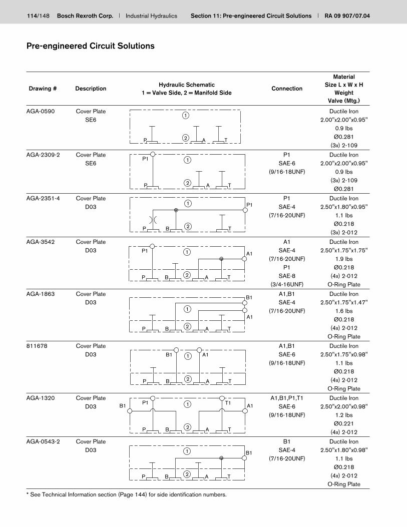
114/148 Bosch Rexroth Corp. Industrial Hydraulics Section 11: Pre-engineered Circuit Solutions RA 09 907/07.04
Pre-engineered Circuit Solutions
Material
Drawing # DescriptionHydraulic Schematic
ConnectionSize L x W x H
1 = Valve Side, 2 = Manifold Side WeightValve (Mtg.)
AGA-0590 Cover Plate Ductile IronSE6 2.00"x2.00"x0.95"
0.9 lbsØ0.281
(3x) 2-109
AGA-2309-2 Cover Plate P1 Ductile IronSE6 SAE-6 2.00"x2.00"x0.95"
(9/16-18UNF) 0.9 lbs(3x) 2-109
Ø0.281
AGA-2351-4 Cover Plate P1 Ductile IronD03 SAE-4 2.50"x1.80"x0.95"
(7/16-20UNF) 1.1 lbsØ0.218
(3x) 2-012
AGA-3542 Cover Plate A1 Ductile IronD03 SAE-4 2.50"x1.75"x1.75"
(7/16-20UNF) 1.9 lbsP1 Ø0.218
SAE-8 (4x) 2-012(3/4-16UNF) O-Ring Plate
AGA-1863 Cover Plate A1,B1 Ductile IronD03 SAE-4 2.50"x1.75"x1.47"
(7/16-20UNF) 1.6 lbsØ0.218
(4x) 2-012O-Ring Plate
811678 Cover Plate A1,B1 Ductile IronD03 SAE-6 2.50"x1.75"x0.98"
(9/16-18UNF) 1.1 lbsØ0.218
(4x) 2-012O-Ring Plate
AGA-1320 Cover Plate A1,B1,P1,T1 Ductile IronD03 SAE-6 2.50"x2.00"x0.98"
(9/16-18UNF) 1.2 lbsØ0.221
(4x) 2-012
AGA-0543-2 Cover Plate B1 Ductile IronD03 SAE-4 2.50"x1.80"x0.98"
(7/16-20UNF) 1.1 lbsØ0.218
(4x) 2-012O-Ring Plate
P A T
1
2
P 2
1
A T
P1
P 2
1
TB
P1
P B 2
1
T
A1
A
P1
P B 2
1
A T
A1
B1
P B 2
1
A T
B1 A1
P B 2
1
A T
P1 T1 A1B1
BP 2
1
TA
B1
* See Technical Information section (Page 144) for side identification numbers.

RA 09 907/07.04 Section 11: Pre-engineered Circuit Solutions Industrial Hydraulics Bosch Rexroth Corp. 115/148
Pre-engineered Circuit Solutions
Material
Drawing # DescriptionHydraulic Schematic
ConnectionSize L x W x H
1 = Valve Side, 2 = Manifold Side WeightValve (Mtg.)
AGA-6824 Cover Plate Ductile IronD03 4.20"x2.30"x1.90"
W/ DBD...6 4.7 lbsCavity Ø0.218
(4x) 2-012O-Ring Plate
AGA-3335-2 Cover Plate P1 Ductile IronD03 SAE-4 4.00"x2.20"x1.75"
W/ DBD...6 (7/16-20UNF) 4.0 lbsCavity Ø0.218
(4x) 2-012
AGA-2052-2 Cover Plate Ductile IronD03 4.70"x2.30"x1.80"
W/ DBD...6 4.0 lbsCavity Ø0.221
(4x) 2-012
AGA-10524 Cover Plate Ductile IronKHP16 3.90"x2.40"x0.80"
1.9 lbsØ0.221
—
AGA-10535 Cover Plate Ductile IronKHP20 4.70"x3.20"x0.80"
3.1 lbsØ0.221
—
AGA-5128 Cover Plate Ductile IronKHP25 5.30"x3.15"x0.80"
3.4 lbsØ0.221
(2x) 27x3
AGA-4070 Cover Plate A1,B1 Ductile IronKHP40 SAE-12 6.90"x5.20"x1.50"
A2,B2 13.9 lbsSAE-4 Ø0.656
(2x) 2-224
P A T
1
2B
P B 2
1
A T
P1
P T 2
1
A B
A
1
B2
A
1
B2
A
1
B2
A 2
1
B
A1 B1A2 B2
* See Technical Information section (Page 144) for side identification numbers.

116/148 Bosch Rexroth Corp. Industrial Hydraulics Section 11: Pre-engineered Circuit Solutions RA 09 907/07.04
Pre-engineered Circuit Solutions
Material
Drawing # DescriptionHydraulic Schematic
ConnectionSize L x W x H
1 = Valve Side, 2 = Manifold Side WeightValve (Mtg.)
AGA-1408-2 Sandwich Plate Ductile IronSE6 2.15"x2.15"x1.40"
1.6 lbsØ0.281
(2x) 8.5x1.5(1x) 2-013
AGA-0942-2 Sandwich Plate A2 Ductile IronSE6 MS-33649-4 2.00"x2.00"x0.95"
(7/16-20UNF) 0.9 lbsØ0.265
(2x) 8.5x1.5(1x) 2-013
AGA-2416 Sandwich Plate P2 Ductile IronSE6 SAE-6 2.50"x2.00"x1.20"
(9/16-18UNF) 1.5 lbsØ0.265
(2x) 8.5x1.5(1x) 2-013
AGA-0663-2 Sandwich Plate A2,A3 Ductile IronSE6 SAE-8 2.50"x2.00"x1.77"
(3/4-16UNF) 2.3 lbsØ0.265
(3x) 2-110
AGA-1779-2 Sandwich Plate Ductile IronSE6 3.30"x2.75"x1.98"
W/ MSR8 4.6 lbsCavity Ø0.281
(3x) 2-013
AGA-0699-2 Sandwich Plate A2 Ductile IronD03 SAE-8 2.55"x1.80"x1.25"
(3/4-16UNF) 1.4 lbsØ0.218
(4x) 2-012
AGA-4256 Sandwich Plate Ductile IronD03 3.50"x1.80"x1.00"
Move A port 1.6 lbs+1.062 Ø0.221
2 Extra bolt (5x) 2-012holes added
AGA-11194 Sandwich Plate Ductile IronD03 2.80"x2.00"x0.75"
1 lbsØ0.218
(4x) 2-012
P A T
1
2
A1P1 T1
P
P1
2
1
A
A1
T
T1A2
P
P1 T1
2 A
1 A1
T
P2
P
A3 P1 T1
2
1
A
A1
T
A2
P
P1
2 A T
T11 A1
A1P1
P
1
2
T1
A TB
B1A2
A1
P
P1
B
B1
2
1
A A2 T
T1
A1
P
P1
B
B1
2
1 T1
A T
* See Technical Information section (Page 144) for side identification numbers.

RA 09 907/07.04 Section 11: Pre-engineered Circuit Solutions Industrial Hydraulics Bosch Rexroth Corp. 117/148
Pre-engineered Circuit Solutions
Material
Drawing # DescriptionHydraulic Schematic
ConnectionSize L x W x H
1 = Valve Side, 2 = Manifold Side WeightValve (Mtg.)
AGA-1246 Sandwich Plate T2 Ductile IronD03 SAE-6 3.00"x1.75"x0.96"
(9/16-18UNF) Ø0.2211.3 lbs
(4x) 2-012O-Ring Plate
AGA-1246 Sandwich Plate P2 Ductile IronD03 SAE-6 3.00"x1.75"x0.96"
(9/16-18UNF) (9/16-18UNF) 1.3 lbsØ0.221
(4x) 2-012O-Ring Plate
AGA-2459 Sandwich Plate Ductile IronD03 2.70"x2.30"x1.80"
2.9 lbsØ0.218
(4x) 2-012
AGA-1362 Sandwich Plate Ductile IronD03 3.80"x3.00"x1.80"
5.3 lbsØ0.234
(4x) 2-012
AGA-7525 Sandwich Plate B1 Ductile IronD03 SAE-4 5.00"x3.00"x1.95"
(7/16-20UNF) 7.6 lbsØ0.218
(4x) 2-012
AGA-8168 Sandwich Plate T2 Ductile IronD03 G 1/4" 3.25"x1.95"x1.76"
2.8 lbsØ0.218
(4x) 2-012O-Ring Plate
AGA-8168 Sandwich Plate P2 Ductile IronD03 G 1/4" 3.25"x1.95"x1.76"
2.8 lbsØ0.218
(4x) 2-012O-Ring Plate
AGA-5296 Sandwich Plate P2 Ductile IronD03 SAE-4 2.80"x2.00"x1.18"
(7/16-20UNF) 1.7 lbsØ0.221
(4x) 2-012
A1
P
P1
B
B1
2
1 T1
A T
T2
P
P1
B
B1
2
1
A
A1
T
T1P2
D03
P B 2
P1 B1 1
A T
A1 T1T
P
B
D03
P B 2
P1 B1 1
A T
A1 T1T
P
B
P 2
P1 1
TAP
T1A1 D03
ATB
B1
P
P1
B
B1
2
1
A
A1
T
T1T2T2
P2P1
P B
B1
2
1 A1
A T
T1P2
BP
P2P1 B1
2
1
TA
A1 T1
* See Technical Information section (Page 144) for side identification numbers.

118/148 Bosch Rexroth Corp. Industrial Hydraulics Section 11: Pre-engineered Circuit Solutions RA 09 907/07.04
Pre-engineered Circuit Solutions
Material
Drawing # DescriptionHydraulic Schematic
ConnectionSize L x W x H
1 = Valve Side, 2 = Manifold Side WeightValve (Mtg.)
AGA-1270-2 Sandwich Plate A2 Ductile IronD03 SAE-6 2.80"x1.80"x1.30"
(9/16-18UNF) 1.7 lbsØ0.218
(4x) 2-012
AGA-3602-2 Sandwich Plate A2,B2,P2,T2 Ductile IronD03 SAE-4 2.55"x2.20"x1.45"
(7/16-20UNF) 2.1 lbsØ0.218
(4x) 2-012
AGA-2872 Sandwich Plate T2 Ductile IronD03 3/8" NPT 3.00"x1.75"x0.96"
1.3 lbsØ0.221
(4x) 2-012O-Ring Plate
AGA-2872 Sandwich Plate P2 Ductile IronD03 3/8" NPT 3.00"x1.75"x0.96"
1.3 lbsØ0.221
(4x) 2-012O-Ring Plate
AGA-0692-2 Sandwich Plate Ductile IronD03 2.55"x1.80"x0.45"
0.5 lbsØ0.218
(4x) 2-012
AGA-1624 Sandwich Plate Ductile IronD03 2.55"x1.80"x0.45"
0.5 lbsØ0.218
(4x) 2-012
AGA-2826 Sandwich Plate Ductile IronD03 4.20"x1.74"x1.45"
2.7 lbsØ0.221
(4x) 2-012
AGA-8415 Sandwich Plate Ductile IronD03 2.50"x2.30"x1.94"
2.9 lbsØ0.218
(4x) 2-012O-Ring Plate
A1
P
P1
B
B1
2
1 T1
A T
A2
P
P1
B
B1
2
1
A
A1
T
T1
A2
T2P2
B2
P
P1
B
B1
2
1
A
A1
T
T1T2
P2
P B 2
P1 B1 1
A T
A1 T1
P
P1
B
B1
2
1
TA
A1 T1
P1
P
1B1
B 2
T1A1
A T
P
P1
B
B1
2
1
A
A1
T
T1
P
P1
B 2
B1 1
A T
A1 T1
* See Technical Information section (Page 144) for side identification numbers.

RA 09 907/07.04 Section 11: Pre-engineered Circuit Solutions Industrial Hydraulics Bosch Rexroth Corp. 119/148
Pre-engineered Circuit Solutions
Material
Drawing # DescriptionHydraulic Schematic
ConnectionSize L x W x H
1 = Valve Side, 2 = Manifold Side WeightValve (Mtg.)
AGA-6875 Sandwich Plate P2 Ductile IronD03 SAE-4 3.50"x3.20"x1.10"
(7/16-20UNF) 3.2 lbsØ0.218
(4x) 2-012
AGA-5899 Sandwich Plate A2,A3 Ductile IronD03 SAE-6 Ø0.218
(9/16-18UNF) (4x) 2-012
AGA-6500 Sandwich Plate Ductile IronD03 2.50"x1.80"x0.95"
1.1 lbsØ0.218
(4x) 2-012O-Ring Plate
AGA-6500 Sandwich Plate Ductile IronD03 2.50"x1.80"x0.95"
1.1 lbsØ0.218
(4x) 2-012O-Ring Plate
AGA-5713 Sandwich Plate Ductile IronD03 2.80"x1.75"x1.25"
1.5 lbsØ0.281
(3x) 2-012
AGA-5921 Sandwich Plate Ductile IronD03 3.05"x1.80"x1.20"
1.7 lbsØ0.218
(4x) 2-012O-Ring Plate
AGA-5921 Sandwich Plate Ductile IronD03 3.05"x1.80"x1.20"
1.7 lbsØ0.218
(4x) 2-012O-Ring Plate
AGA-4551 Sandwich Plate A2 Ductile IronD03 SAE-6 2.75"x1.75"x1.20"
(9/16-18UNF) 1.5 lbsØ0.218
(4x) 2-012
A1
P
P1
B
B1
2
1 T1
A T
P2
A2
P
P1
B
B1
2
1
A
A1
T
T1
A3
P
P1
B
B1
2
1
A
A1
T
T1
P
P1
B 2
B1 1
A
A1
T
T1
P 2
P1 1
A T
A1 T1
P
P1
B
B1
2
1
A
A1
T
T1
P1
P B
B1
2
1 A1
A T
T1
P1
P B
B1
2
1 A1
A T
T1 A2
* See Technical Information section (Page 144) for side identification numbers.
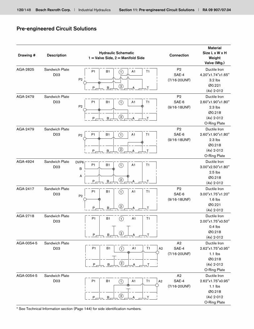
120/148 Bosch Rexroth Corp. Industrial Hydraulics Section 11: Pre-engineered Circuit Solutions RA 09 907/07.04
Pre-engineered Circuit Solutions
Material
Drawing # DescriptionHydraulic Schematic
ConnectionSize L x W x H
1 = Valve Side, 2 = Manifold Side WeightValve (Mtg.)
AGA-2825 Sandwich Plate P2 Ductile IronD03 SAE-4 4.20"x1.74"x1.65"
(7/16-20UNF) 3.2 lbsØ0.221
(4x) 2-012
AGA-2479 Sandwich Plate P2 Ductile IronD03 SAE-6 2.60"x1.90"x1.80"
(9/16-18UNF) 2.3 lbsØ0.218
(4x) 2-012O-Ring Plate
AGA-2479 Sandwich Plate P2 Ductile IronD03 SAE-6 2.60"x1.90"x1.80"
(9/16-18UNF) 2.3 lbsØ0.218
(4x) 2-012O-Ring Plate
AGA-4924 Sandwich Plate Ductile IronD03 3.00"x2.50"x1.80"
2.5 lbsØ0.218
(4x) 2-012
AGA-2417 Sandwich Plate P2 Ductile IronD03 SAE-6 3.00"x1.75"x1.20"
(9/16-18UNF) 1.6 lbsØ0.221
(4x) 2-012
AGA-2718 Sandwich Plate Ductile IronD03 2.00"x1.75"x0.50"
0.4 lbsØ0.218
(4x) 2-012
AGA-0054-5 Sandwich Plate A2 Ductile IronD03 SAE-4 2.62"x1.75"x0.95"
(7/16-20UNF) 1.1 lbsØ0.218
(4x) 2-012O-Ring Plate
AGA-0054-5 Sandwich Plate A2 Ductile IronD03 SAE-4 2.62"x1.75"x0.95"
(7/16-20UNF) 1.1 lbsØ0.218
(4x) 2-012O-Ring Plate
P2
BP
P1 B1
2
1
TA
A1 T1
P
P1
B
B1
2
1
A
A1
T
T1P2
P2
P B 2
P1 B1 1
A T
A1 T1
P
P1
B 2
B1 1
A
A1
T
T1DVP6
B
A
P2
P
P1
B 2
B1 1
A
A1
T
T1
P1
P
1B1
B 2
T1A1
A T
P1
P B
B1
2
1
A
A1
T
T1 A2
TABP
P1 B1
2
1 A1 T1 A2
* See Technical Information section (Page 144) for side identification numbers.

RA 09 907/07.04 Section 11: Pre-engineered Circuit Solutions Industrial Hydraulics Bosch Rexroth Corp. 121/148
Pre-engineered Circuit Solutions
Material
Drawing # DescriptionHydraulic Schematic
ConnectionSize L x W x H
1 = Valve Side, 2 = Manifold Side WeightValve (Mtg.)
AGA-2631 Sandwich Plate P2,T2 Ductile IronD03 SAE-6 2.75"x1.75"x1.20"
(9/16-18UNF) 1.5 lbsØ0.218
(4x) 2-012O-Ring Plate
AGA-2631 Sandwich Plate P2,T2 Ductile IronD03 SAE-6 2.75"x1.75"x1.20"
(9/16-18UNF) 1.5 lbsØ0.218
(4x) 2-012O-Ring Plate
AGA-2630 Sandwich Plate P2,T2 Ductile IronD03 SAE-6 2.75"x1.75"x1.20"
(9/16-18UNF) 1.5 lbsØ0.218
(4x) 2-012O-Ring Plate
AGA-2630 Sandwich Plate P2,T2 Ductile IronD03 SAE-6 2.75"x1.75"x1.20"
(9/16-18UNF) 1.5 lbsØ0.218
(4x) 2-012O-Ring Plate
AGA-2076-3 Sandwich Plate B2 Ductile IronD03 SAE-6 2.55"x1.80"x1.10"
(9/16-18UNF) 1.3 lbsØ0.218
(4x) 2-012
AGA-1662-3 Sandwich Plate P2 Ductile IronD03 SAE-6 3.00"x1.75"x0.96"
(9/16-18UNF) 1.3 lbsØ0.221
(4x) 2-012
AGA-1662-3 Sandwich Plate T2 Ductile IronD03 SAE-6 3.00"x1.75"x0.96"
(9/16-18UNF) 1.3 lbsØ0.221
(4x) 2-012O-Ring Plate
AGA-1314 Sandwich Plate P2 Ductile IronD03 SAE-4 2.50"x1.75"x1.15"
(7/16-20UNF) 1.3 lbsØ0.221(4x) 8x2
BP
P1 B1
2
1
TA
A1 T1P2 T2
P2
P
P1
B
B1
2
1 T2
A
A1
T
T1
P2
P
P1
B
B1
2
1 T2
A
A1
T
T1
P2
P B 2
P1 B1 1 T2
A T
A1 T1
B2
P
P1
B
B1
2
1
A
A1
T
T1
T2P1
P B
B1
2
1
A
A1
T
T1
P2 P1
P
1B1
B 2
A1
A
T1
T
P2 P1
P B
B1
2
1
A
A1
T
T1
* See Technical Information section (Page 144) for side identification numbers.

122/148 Bosch Rexroth Corp. Industrial Hydraulics Section 11: Pre-engineered Circuit Solutions RA 09 907/07.04
Pre-engineered Circuit Solutions
Material
Drawing # DescriptionHydraulic Schematic
ConnectionSize L x W x H
1 = Valve Side, 2 = Manifold Side WeightValve (Mtg.)
AGA-1794 Sandwich Plate P2 Ductile IronD03 SAE-6 3.25"x1.75"x1.94"
(9/16-18UNF) 2.8 lbsØ0.234
(4x) 2-012O-Ring Plate
AGA-1794 Sandwich Plate T2 Ductile IronD03 SAE-6 3.25"x1.75"x1.94"
(9/16-18UNF) 2.8 lbsØ0.234
(4x) 2-012O-Ring Plate
AGA-1851 Sandwich Plate Ductile IronD03 2.50"x1.75"x0.72"
0.8 lbsØ0.218
(4x) 2-012O-Ring Plate
AGA-1851 Sandwich Plate Ductile IronD03 2.50"x1.75"x0.72"
0.8 lbsØ0.218
(4x) 2-012O-Ring Plate
AGA-1478-2 Sandwich Plate P2 Ductile IronD03 SAE-4 3.00"x1.75"x1.10"
(7/16-20UNF) 1.5 lbsØ0.221
(4x) 2-012O-Ring Plate
AGA-1478-2 Sandwich Plate T2 Ductile IronD03 SAE-4 3.00"x1.75"x1.10"
(7/16-20UNF) 1.5 lbsØ0.221
(4x) 2-012O-Ring Plate
AGA-1394-2 Sandwich Plate P2 Ductile IronD03 SAE-4 2.80"x1.75"x1.40"
(7/16-20UNF) 1.7 lbsØ0.218
(4x) 2-012O-Ring Plate
AGA-1394-2 Sandwich Plate T2 Ductile IronD03 SAE-4 2.80"x1.75"x1.40"
(7/16-20UNF) 1.7 lbsØ0.218
(4x) 2-012O-Ring Plate
BP
P1 B1
2
1
TA
A1 T1P2P2
T2
P
P1
B
B1
2
1T2
A
A1
T
T1
P B 2
P1 B1 1
A T
A1 T1
P
P1
B 2
B1 1
A
A1
T
T1
T1A1B1P1
AP B 2
1
T
P2
T2P1
P
1B1
B 2
A1
A
T1
T
P2 P1
P
1B1
B 2
A1
A
T1
T
P1
P B
B1
2
1 T2
A
A1
T
T1
* See Technical Information section (Page 144) for side identification numbers.

RA 09 907/07.04 Section 11: Pre-engineered Circuit Solutions Industrial Hydraulics Bosch Rexroth Corp. 123/148
Pre-engineered Circuit Solutions
Material
Drawing # DescriptionHydraulic Schematic
ConnectionSize L x W x H
1 = Valve Side, 2 = Manifold Side WeightValve (Mtg.)
AGA-0563-2 Sandwich Plate A2 Ductile IronD03 SAE-4 2.50"x1.75"x0.95"
(7/16-20UNF) 1 lbsØ0.218
(4x) 2-012O-Ring Plate
AGA-0677-2 Sandwich Plate B2 Ductile IronD03 SAE-8 2.55"x1.80"x1.58"
(3/4-16UNF) 1.8 lbsØ0.218
(4x) 2-012
AGA-5437 Sandwich Plate Ductile IronD03 4.80"x2.30"x2.00"
Offset to 5.7 lbs“A” side Ø0.218
(4x) 2-012
AGA-1124 Sandwich Plate Ductile IronD03 3.30"x2.40"x1.80"
3.7 lbsØ0.218
(4x) 2-012
AGA-0228-2 Sandwich Plate T2 Ductile IronD03 SAE-4 2.80"x1.75"x1.40"
(7/16-20UNF) 1.7 lbsØ0.218
(4x) 2-012O-Ring Plate
AGA-0228-2 Sandwich Plate P2 Ductile IronD03 SAE-4 2.80"x1.75"x1.40"
(7/16-20UNF) 1.7 lbsØ0.218
(4x) 2-012O-Ring Plate
AGA-0911-2 Sandwich Plate P2 Ductile IronD03 SAE-8 3.55"x1.80"x1.40"
(3/4-16UNF) 2.3 lbsØ0.218
(4x) 2-012
AGA-0692-3 Sandwich Plate Ductile IronD03 3.05"x1.80"x1.20"
2.3 lbsØ0.218
(4x) 2-012
BP
P1 B1
2
1
TA
A1 T1 A2
P
P1
B
B1
2
1B2
A
A1
T
T1
P B 2
P1 B1 1
A T
A1 T1
D03
T
P
BBP 2
B1P1 1
TA
T1A1
P1
P B
B1
2
1
A T
A1 T1 T2
P1
P
1B1
B 2
T1A1
A T
P2
P1
P
B1
B 2
1
A
A1
T
T1P2
TABP
P1 B1
2
1 A1 T1
* See Technical Information section (Page 144) for side identification numbers.

124/148 Bosch Rexroth Corp. Industrial Hydraulics Section 11: Pre-engineered Circuit Solutions RA 09 907/07.04
Material
Drawing # DescriptionHydraulic Schematic
ConnectionSize L x W x H
1 = Valve Side, 2 = Manifold Side WeightValve (Mtg.)
AGA-0086-3 Sandwich Plate T2 Ductile IronD03 SAE-4 2.90"x1.75"x0.95"
(7/16-20UNF) 1.2 lbsØ0.201
(4x) 2-012
AGA-0201-2 Sandwich Plate P2 Ductile IronD03 SAE-4 2.50"x1.90"x0.95"
(7/16-20UNF) 1.2 lbsØ0.201
(4x) 2-012
AGA-1238 Sandwich Plate P2,T2 Ductile IronD03 SAE-6 3.25"x1.90"x1.20"
(9/16-18UNF) 1.9 lbsØ0.221(4x) 8x2
AGA-3754 Sandwich Plate Ductile IronD03 3.40"x2.3"x1.80"
3.6 lbsØ0.218
(4x) 2-012
AGA-0884-2 Sandwich Plate Ductile IronD03 2.70"x2.3"x1.80"
2.9 lbsØ0.218
(4x) 2-012
AGA-1087 Sandwich Plate Ductile IronD03 3.10"x2.3"x1.80"
3.3 lbsØ0.218
(4x) 2-012
AGA-8169 Sandwich Plate P2 Ductile IronD03 G 1/4" 3.25"x1.95"x1.75"
2.8 lbsØ0.218
(4x) 2-012O-Ring Plate
AGA-5574 Sandwich Plate P2 Ductile IronD03 SAE-8 3.00"x2.00"x1.75"
(3/4-16UNF) 2.7 lbsØ0.218
(4x) 2-012
Pre-engineered Circuit Solutions
BP
P1 B1
2
1
TA
A1 T1 T2
P
P1
B
B1
2
1
A
A1
T
T1P2
P2
P B 2
P1 B1 1
A T
A1 T1 T2
BP 2
B1P1 1
TAB
P
T1A1D03
T
P B 2 A TB
P
P1 B1 1 A1 T1D03
T
D03
T
P
BP B 2 A T
P1 B1 1 A1 T1
P1
P
P2
B 2
B1 1 T1
A T
A1 P2
TABP
P1P2 B1
2
1 T1A1
* See Technical Information section (Page 144) for side identification numbers.

RA 09 907/07.04 Section 11: Pre-engineered Circuit Solutions Industrial Hydraulics Bosch Rexroth Corp. 125/148
Material
Drawing # DescriptionHydraulic Schematic
ConnectionSize L x W x H
1 = Valve Side, 2 = Manifold Side WeightValve (Mtg.)
AGA-7547 Sandwich Plate Ductile IronD03 6.00"x3.00"x1.90"
W/ DBD...6 8.8 lbsCavity Ø0.218
(4x) 2-012O-Ring Plate
AGA-6575 Sandwich Plate Ductile IronD03 4.70"x4.00"x1.70"
8.3 lbsØ0.218
(4x) 2-012O-Ring Plate
AGA-7065 Sandwich Plate Ductile IronD03 3.80"x2.50"x1.60"
3.9 lbsØ0.218
(4x) 2-012
AGA-4775 Sandwich Plate A2,B2 Ductile IronD03 SAE-8 5.10"x2.20"x1.80"
W/ WVE 1/2-20 (3/4-16UNF) 5.2 lbsCavity Ø0.218
(4x) 2-012
AGA-6823 Sandwich Plate Ductile IronD03 4.20"x2.20"x1.85"
W/ DBD...6 4.4 lbsCavity Ø0.218
(4x) 2-012O-Ring Plate
AGA-5674 Sandwich Plate P2 Ductile IronD03 SAE-4 4.30"x2.00"x1.80"
W/ WVE 1/2-20 (7/16-20UNF) 4.0 lbsCavity Ø0.218
(4x) 2-012
AGA-2076-4 Sandwich Plate Ductile IronD03 4.80"x3"x1.88"
W/ DBD...6 7.0 lbsCavity Ø0.218
(4x) 2-012
AGA-2076-2 Sandwich Plate B2 Ductile IronD03 SAE-6 2.55"x1.80"x1.10"
(9/16-18UNF) 1.3 lbsØ0.218
(4x) 2-012
Pre-engineered Circuit Solutions
BP
P1 B1
2
1
TA
A1 T1
P1
P B
B1
2
1 A1
A T
T1 P2 T2A2
T1P1
P B 2 A
B1 A11
T
A2 T2
P
P1
B 2
B1 1
A
A1
T
T1A2B2
P1
P B
B1
2
1 A1
A T
T1
P2
P B 2
P1 B1 1
A T
A1 T1
B2
P B A2 T
A1P1 B1 1 T1
B1P1
P B
1
2
T1A1
A T
* See Technical Information section (Page 144) for side identification numbers.

126/148 Bosch Rexroth Corp. Industrial Hydraulics Section 11: Pre-engineered Circuit Solutions RA 09 907/07.04
Material
Drawing # DescriptionHydraulic Schematic
ConnectionSize L x W x H
1 = Valve Side, 2 = Manifold Side WeightValve (Mtg.)
AGA-1853-3 Sandwich Plate Ductile IronD03 4.10"x2.30"x1.80"
W/ DBD...6 4.4 lbsCavity Ø0.234
(4x) 2-012
AGA-1855-2 Sandwich Plate B2 Ductile IronD03 SAE-6 4.85"x2.10"x1.60"
W/ DBD...6 (9/16-18UNF) 4.2 lbsCavity Ø0.218
(4x) 2-012
AGA-1967 Sandwich Plate Ductile IronD03 4.00"x2.10"x1.75
W/ DBD...6 3.8 lbsCavity Ø0.218
(4x) 2-012
AGA-1836 Sandwich Plate Ductile IronD03 4.00"x2.10"x1.75"
W/ DBD...6 3.8 lbsCavity on A side Ø0.218
(4x) 2-012
AGA-1880 Sandwich Plate Ductile IronD03 4.00"x2.10"x1.75"
W/ DBD...6 3.8 lbsCavity on B side Ø0.218
(4x) 2-012
AGA-1116-2 Sandwich Plate Ductile IronD03 4.10"x3.00"x1.80"
W/ DBD...6 5.4 lbsCavity Ø0.218
(4x) 2-012
AGA-0407 Sandwich Plate Ductile IronD03 3.40"x2.50"x1.90"
W/ DVE...6 4.1 lbsCavity Ø0.218
(4x) 2-012O-Ring Plate
AGA-0407 Sandwich Plate Ductile IronD03 3.40"x2.50"x1.90"
W/ DVE...6 4.1 lbsCavity Ø0.218
(4x) 2-012O-Ring Plate
Pre-engineered Circuit Solutions
P
P1
B
B1
2
1
A
A1
T
T1
P
P1
B
B1
2
1
A
A1
T
T1P2
P B 2
P1 B1 1
A T
A1 T1
P1
P
1B1
B 2
A1
A
T1
T
P B 2
P1 B1 1
A T
A1 T1
P
P1
B
B1
2
1
A
A1
T
T1
P1
P B
B1
2
1 A1
A T
T1
P1
P
1B1
B 2
A1
A
T1
T
* See Technical Information section (Page 144) for side identification numbers.
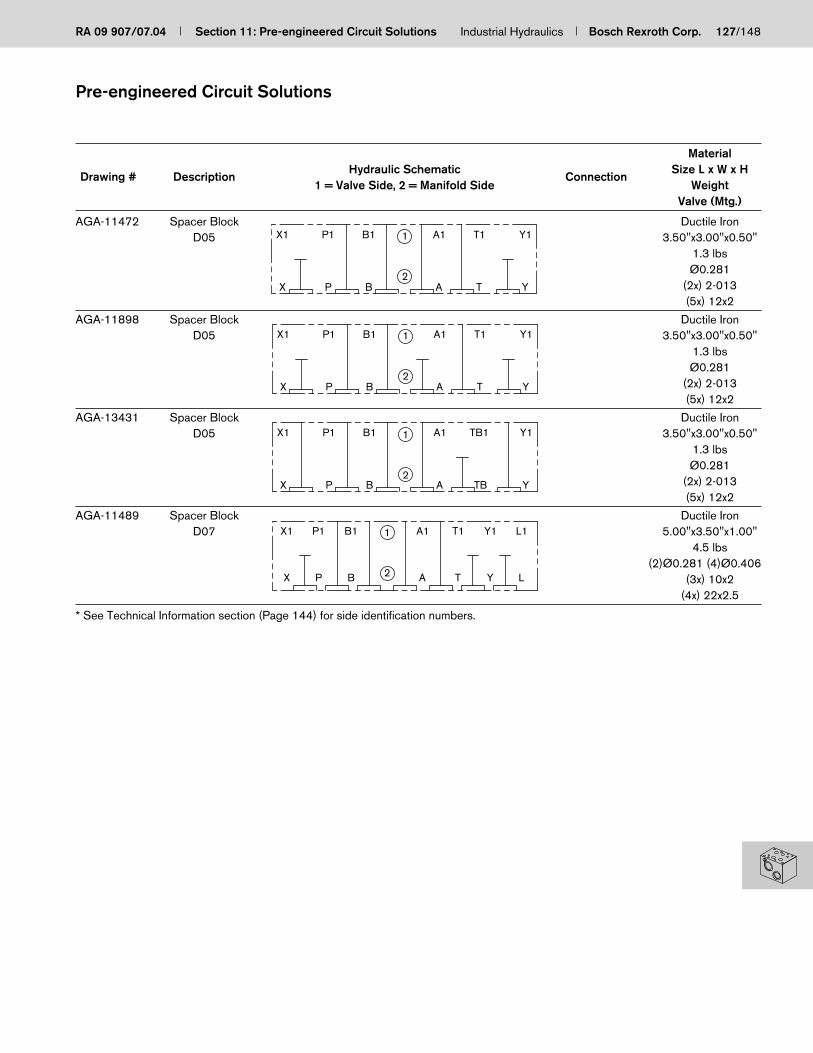
RA 09 907/07.04 Section 11: Pre-engineered Circuit Solutions Industrial Hydraulics Bosch Rexroth Corp. 127/148
Material
Drawing # DescriptionHydraulic Schematic
ConnectionSize L x W x H
1 = Valve Side, 2 = Manifold Side WeightValve (Mtg.)
AGA-11472 Spacer Block Ductile IronD05 3.50"x3.00"x0.50"
1.3 lbsØ0.281
(2x) 2-013(5x) 12x2
AGA-11898 Spacer Block Ductile IronD05 3.50"x3.00"x0.50"
1.3 lbsØ0.281
(2x) 2-013(5x) 12x2
AGA-13431 Spacer Block Ductile IronD05 3.50"x3.00"x0.50"
1.3 lbsØ0.281
(2x) 2-013(5x) 12x2
AGA-11489 Spacer Block Ductile IronD07 5.00"x3.50"x1.00"
4.5 lbs(2)Ø0.281 (4)Ø0.406
(3x) 10x2(4x) 22x2.5
Pre-engineered Circuit Solutions
P
P1
B
B1
2
1
A
A1
T
T1
X
X1
Y
Y1
X
X1
P
P1
B
B1
2
1 T1
TA
A1
Y
Y1
X
X1
P B2
P1 B1 1
TBA Y
TB1A1 Y1
2
1
X
X1
P
P1
B
B1
L
L1Y1
Y
T1
T
A1
A
* See Technical Information section (Page 144) for side identification numbers.

128/148 Bosch Rexroth Corp. Industrial Hydraulics Section 11: Pre-engineered Circuit Solutions RA 09 907/07.04
Material
Drawing # DescriptionHydraulic Schematic
ConnectionSize L x W x H
1 = Valve Side, 2 = Manifold Side WeightValve (Mtg.)
AGA-13482 Valve Adaptor Aluminum
2.75"x2.50"x0.75"
0.5 lbs
10-24 x 0.65 DP.
1/4-20 x 1.25"
(5x) 12x2mm
AGA-14005 Valve Adaptor Ductile Iron
4.00"x3.25"x1.50"
5.7 lbs
1/4-20 x 0.75 DP.
5/16-18 x 1.5"
(5x) 2-013
AGA-13764 Valve Adaptor Ductile Iron
9.00"x8.00"x3.50"
65.5 lbs
1/2-13 x 1.25 DP.
3/4-10 x 3.5"
(4x) 42x3mm
(2x) 19x3mm
Pre-engineered Circuit Solutions
PTA B 2
1
TBA
P1 B1 A1T1
D03
D05
P
P1
B
B1
2
1
A
A1
T
T1
X
X1
4WS2EM10-5X/...
4WS2EM10A-4X/...
Size 32
Size 25/32
X
X1
P
P1
B2
B1 1
T
T1
A
A1
Y
Y1
* See Technical Information section (Page 144) for side identification numbers.

RA 09 907/07.04 Section 11: Pre-engineered Circuit Solutions Industrial Hydraulics Bosch Rexroth Corp. 129/148
Material
Drawing # DescriptionHydraulic Schematic
ConnectionSize L x W x H
1 = Valve Side, 2 = Manifold Side WeightValve (Mtg.)
AGA-2750 Cover Plate B1 Ductile IronD05 SAE-6 3.50"x2.75"x0.85"
(9/16-18UNF) 2.1 lbsØ0.265
(5x) 12x2mmO-Ring Plate
AGA-3564 Cover Plate P1 Ductile IronD05 SAE-6 3.70"x2.75"x0.95"
(9/16-18UNF) 2.5 lbsØ0.281
(5x) 12x2mm
AGA-2617 Cover Plate Ductile IronD05 3.65"x2.75"x0.95"
2.5 lbsØ0.281
(5x) 12x2mm
AGA-0640-2 Cover Plate Ductile IronD05 3.62"x2.75"x0.80"
2 lbsØ0.296
(4x) 12x2mm
AGA-5516 Cover Plate Ductile IronD05 3.60"x2.75"x1.95"
5 lbsØ0.281
(5x) 12x2mm(2x) 2-013
AGA-14217 Cover Plate Ductile IronD05 3.50"x3.00"x1.70"
4.6 lbsØ0.281
(5x) 12x2mm(1x) 2-010
AGA-13002 Cover Plate P1 Ductile IronD05 SAE-4 3.50"x3.00"x1.00"
(7/16-20UNF) 2.7 lbsØ0.281
(5x) 12x2mm(1x) 2-011(1x) 2-013(1x) 2-016
Pre-engineered Circuit Solutions
PTA B 2
1
A
1
2
P1
X Y TA X YTBAP B
PTA B
1
2 A TB L
PTA B 2
1
A TB
P A TB
1
2B
B1
TA
TA P B A2
1
TB
P1
PTA B 2
1
TBAX Y
* See Technical Information section (Page 144) for side identification numbers.

130/148 Bosch Rexroth Corp. Industrial Hydraulics Section 11: Pre-engineered Circuit Solutions RA 09 907/07.04
Material
Drawing # DescriptionHydraulic Schematic
ConnectionSize L x W x H
1 = Valve Side, 2 = Manifold Side WeightValve (Mtg.)
AGA-1410-2 Cover Plate Ductile IronD08 6.40"x4.75"x2.15"
16.9 lbsØ0.531
(4x) 27x3mm
AGA-1366 Cover Plate Ductile IronD10 9.50"x7.75"x0.98"
18.75 lbsØ0.781
(4x) 42x3mm(2x) 19x3mm
AGA-5394 Cover Plate Ductile IronD10 9.50"x7.75"x2.40"
45.9 lbsØ0.781
(4x) 42x3mm(2x) 19x3mm
AGA-7557 Cover Plate X1 Ductile IronD10 SAE-4 10.50"x7.75"x2.90"
32/35 (7/16-20UNF) 61.3 lbsP1 Ø0.781
SAE-20 (4x) 42x3mm(1 5/8-12UN) (2x) 19x3mm
AGA-2574 Cover Plate Ductile IronCheck valve S 3.5"x3.5"x0.95"
Subplate Pattern 3 lbsSize 10 Ø0.406
(2x) 15x3mm
AGA-2863 Cover Plate Ductile IronCheck valve S 4.5"x3.5"x1.70"
Subplate Pattern 6.9 lbsSize 20 Ø0.656
(2x) 24x3mm
AGA-2573 Cover Plate Ductile IronCheck valve S 5.20"x5.20"x1.80"
Subplate Pattern 12.6 lbsSize 30 Ø0.781
(2x) 34x3mm
Pre-engineered Circuit Solutions
P B 2
1
TA
P B 2
1
A T YX
X P B 2
1
TA Y
X P B 2
1
TA Y
P1X1
1
2A B
A
1
2 B
A 2
1
B
* See Technical Information section (Page 144) for side identification numbers.

RA 09 907/07.04 Section 11: Pre-engineered Circuit Solutions Industrial Hydraulics Bosch Rexroth Corp. 131/148
Material
Drawing # DescriptionHydraulic Schematic
ConnectionSize L x W x H
1 = Valve Side, 2 = Manifold Side WeightValve (Mtg.)
AGA-2171 Cover Plate Ductile IronP06 3.40"x2.70"x0.45"
SL,SV,DR,DZ,FD 1 lbsSize 10 Ø0.437
(2x) 2-012(2x) 2-115
AGA-2172 Cover Plate Ductile IronP08 4.00"x3.80"x1.40"
SL,SV,DR,DZ,FD 5.5 lbsSize 20 Ø0.437
(2x) 2-012(2x) 2-216
AGA-5732 Cover Plate Ductile IronP10 5.55"x4.75"x1.20"
SL,SV,DR,DZ,FD 8.2 lbsSize 30 Ø0.437
(2x) 2-012(2x) 2-220
AGA-3169-2 Cover Plate Ductile IronP06 3.40"x2.70"x1.20"
SL,SV,DR,DZ,FD 2.8 lbsSize 10 Ø0.421
(2x) 15x3mm(2x) 10x2.5mm
AGA-6395 Cover Plate Ductile IronP06 3.40"x2.70"x1.20"
SL,SV,DR,DZ,FD 2.8 lbsSize 10 Ø0.406
(2x) 15x3mm(2x) 10x2.5mm
AGA-8134 Cover Plate Ductile IronP08 4.20"x3.75"x1.75"
SL,SV,DR,DZ,FD 7.1 lbsSize 20 Ø0.406
(2x) 2-012(2x) 2-216
AGA-5152 Cover Plate Ductile IronP10 4.65"x4.60"x1.80"
SL,SV,DR,DZ,FD 10 lbsSize 30 Ø0.406
(2x) 2-012(2x) 2-220
AGA-6394 Cover Plate Ductile IronP10 5.55"x4.75"x2.20"
SL,SV,DR,DZ,FD 15 lbsSize 30 Ø0.421
(2x) 2-012(2x) 2-220
Pre-engineered Circuit Solutions
1
2A B YX
X A 2
1
B Y
X A 2
1
B Y
X A 2
1
B Y
X A 2
1
B Y
X A 2
1
B Y
X A 2
1
B Y
X A 2
1
B Y
* See Technical Information section (Page 144) for side identification numbers.

132/148 Bosch Rexroth Corp. Industrial Hydraulics Section 11: Pre-engineered Circuit Solutions RA 09 907/07.04
Material
Drawing # DescriptionHydraulic Schematic
ConnectionSize L x W x H
1 = Valve Side, 2 = Manifold Side WeightValve (Mtg.)
AGA-2606 Cover Plate Ductile IronRelief Valve DB 3.00"x2.25"x0.95"
Subplate Pattern 1.6 lbsSize 6 Ø0.281
(2x) 7x1.5mm
AGA-2607 Cover Plate Ductile IronRelief Valve DB 3.50"x3.00"x0.95"
Subplate Pattern 2.5 lbsSize 10 Ø0.343
(2x) 12.3x2.4mm
AGA-2608 Cover Plate Ductile IronSubplate Pattern 4.75"x3.50"x1.20"Relief Valve DB 5.1 lbs
Size 20 Ø0.343(2x) 22x3mm
AGA-2609 Cover Plate Ductile IronRelief Valve DB 6.25"x4.75"x1.45"
Subplate Pattern 11.1 lbsSize 30 Ø0.406
(2x) 34x3mm
AGA-2453-2 Cover Plate Ductile IronR06 3.30"x3.30"x0.70"
Size 10 1.9 lbsØ0.531
(1x) 2-012(2x) 2-115
AGA-1563-2 Cover Plate Ductile IronW/ DBD...6 4.30"x3.05"x1.50"R06 Size 10 5.1 lbs
Cavity Ø0.531(2x) 2-115
AGA-2169-2 Cover Plate Ductile IronR08 4.85"x4.00"x0.55"
Size 20 2.7 lbsØ0.656
(1x) 2-012(2x) 2-216
AGA-1367 Cover Plate Ductile IronR10 5.80"x4.60"x0.99"
Size 30 6.8 lbsØ0.781
(2x) 2-220
Pre-engineered Circuit Solutions
1
2P T
P 2
1
T
P 2
1
T
P 2
1
T
X 2
1
BA
A
1
2 B
X A
1
2 B
A 2
1
B
* See Technical Information section (Page 144) for side identification numbers.

RA 09 907/07.04 Section 11: Pre-engineered Circuit Solutions Industrial Hydraulics Bosch Rexroth Corp. 133/148
Material
Drawing # DescriptionHydraulic Schematic
ConnectionSize L x W x H
1 = Valve Side, 2 = Manifold Side WeightValve (Mtg.)
AGA-1384 Cover Plate Ductile IronFlow Valve DVP 1.90"x1.85"x0.48"
Size 8 0.5 lbsØ0.281
(2x) 9x2mm
AGA-1759 Cover Plate Ductile IronFlow Valve DVP 2.10"x1.90"x0.90"
Size 8 0.9 lbsØ0.281
(2x) 9x2mm
AGA-1502-2 Cover Plate Ductile IronFlow Valve DRVP 2.80"x1.90"x0.90"
Size 8 1.2 lbsØ0.281
(2x) 9x2mm
AGA-5373 Cover Plate Ductile IronFlow Valve DVP 2.00"x2.00"x0.75"
Size 10 0.8 lbsØ0.281
(2x) 12x2mm
AGA-1009-3 Cover Plate Ductile IronFlow Valve DVP 3.70"x2.75"x0.82"
Size 16 2.1 lbsØ0.343
(2x) 2-117
AGA-1219 Cover Plate Ductile IronFlow Valve DVP 4.40"x3.00"x0.95"
Size 20 3.2 lbsØ0.343
(2x) 2-213
AGA-0857 Cover Plate Ductile IronFlow Valve DVP 5.65"x3.95"x0.70"
Size 25 4 lbsØ0.406
(2x) 2-217
AGA-5153 Cover Plate Ductile IronFlow Valve RVP 7.30"x4.55"x2.20"
Size 30 18.9 lbsØ0.531
(2x) 39x3mm
Pre-engineered Circuit Solutions
1
2A B
1
2A B
A 2
1
B
1
2A B
1
2A B
1
2A B
1
2A B
A 2
1
B
* See Technical Information section (Page 144) for side identification numbers.

134/148 Bosch Rexroth Corp. Industrial Hydraulics Section 11: Pre-engineered Circuit Solutions RA 09 907/07.04
Material
Drawing # DescriptionHydraulic Schematic
ConnectionSize L x W x H
1 = Valve Side, 2 = Manifold Side WeightValve (Mtg.)
AGA-3375 Cover Plate Ductile Iron2F06 2.36"x2.36"x0.90"
2FRM 5 1.3 lbsØ0.218
(2x) 12x2.5mm
AGA-2437 Cover Plate Ductile Iron2F07 4.00"x3.75"x0.98"
2FRM 10 3.8 lbsØ0.343
(2x) 2-210
AGA-1558 Cover Plate Ductile Iron2F07 3.75"x3.62"x1.24"
2FRM 10 4.3 lbsØ0.343
(2x) 2-210
AGA-0760 Cover Plate Ductile Iron2F08 4.90"x4.90"x0.70"
2FRM 16 4.3 lbsØ0.406
(2x) 2-215
AGA-7876 Cover Plate Ductile Iron2F08 4.90"x4.90"x1.50"
2FRM 16 9.3 lbsØ0.406
(2x) 2-215
AGA-2128-3 Cover Plate Ductile IronR08 4.50"x3.80"x1.80"
Size 20 8 lbsØ0.656
(2x) 2-216
AGA-0961-2 Cover Plate Ductile IronP06 3.62"x2.80"x1.25"
SL,SV,DR,DZ,FD 3.2 lbsSize 10 Ø0.437
(2x) 2-012(2x) 2-115
AGA-2736-2 Cover Plate Ductile IronP06 3.62"x2.80"x1.25"
SL,SV,DR,DZ,FD 3.2 lbsSize 10 Ø0.406
(2x) 2-012(2x) 2-115
Pre-engineered Circuit Solutions
1
2A B
1
2A B
A 2
1
B
1
2A B
A 2
1
B
A 2
1
B
X A 2
1
B Y
X A 2
1
B Y
* See Technical Information section (Page 144) for side identification numbers.

RA 09 907/07.04 Section 11: Pre-engineered Circuit Solutions Industrial Hydraulics Bosch Rexroth Corp. 135/148
Material
Drawing # DescriptionHydraulic Schematic
ConnectionSize L x W x H
1 = Valve Side, 2 = Manifold Side WeightValve (Mtg.)
AGA-3756 Cover Plate A1 Ductile IronP06 G 1/4" 3.40"x2.90"x2.20"
SL,SV,DR,DZ,FD A2 5.6 lbsSize 10 G 1" Ø0.421
(2x) 10x2.5mm(2x) 15x2mm
AGA-4448 Cover Plate A1 Ductile IronP08 SAE-12 4.50"x4.00"x1.80"
SL,SV,DR,DZ,FD (1 1/16-12UN) 8.4 lbsSize 20 Ø0.421
(2x) 2-012(2x) 2-216
AGA-1795-2 Cover Plate B1 Ductile IronP08 SAE-20 4.00"x3.80"x1.40"
SL,SV,DR,DZ,FD (1 5/8-12UN) 5.5 lbsSize 20 Ø0.406
(2x) 2-012(2x) 2-216
AGA-2575 Cover Plate Ductile IronP10 5.50"x4.75"x2.20"
SL,SV,DR,DZ,FD 15 lbsSize 30 Ø0.406
(1x) 2-012(2x) 2-220
AGA-1368 Cover Plate Ductile IronP10 5.50"x4.75"x0.70"
SL,SV,DR,DZ,FD 4.7 lbsSize 30 Ø0.406
(1x) 2-012(2x) 2-220
AGA-2677 Cover Plate Ductile IronD07 5.40"x3.63"x1.45"
7.3 lbs(4x) Ø0.406(2x) Ø0.281(2x) 10x2mm
(4x) 22x2.5mmAGA-3308 Cover Plate Ductile Iron
D07 5.50"x3.50"x0.95"4.7 lbs
(4x) Ø0.406(2x) Ø0.281(1x) 10x2mm
(4x) 22x2.5mmAGA-1159 Cover Plate Ductile Iron
D07 5.40"x3.63"x1.45"7.3 lbs
(4x) Ø0.406(2x) Ø0.281(2x) 10x2mm
(4x) 22x2.5mm
Pre-engineered Circuit Solutions
X A 2
1
B Y
A1A2
A1
AX 2
1
B Y
X A 2
1
B Y
B1
A 2
1
B Y
A 2 B Y
1
BPX A T Y2
1
P B 2
1
TA L
X P B 2
1
TA Y
* See Technical Information section (Page 144) for side identification numbers.

136/148 Bosch Rexroth Corp. Industrial Hydraulics Section 11: Pre-engineered Circuit Solutions RA 09 907/07.04
Material
Drawing # DescriptionHydraulic Schematic
ConnectionSize L x W x H
1 = Valve Side, 2 = Manifold Side WeightValve (Mtg.)
AGA-3630 Sandwich Plate P2 Ductile IronD05 SAE-4 3.80"x2.75"x1.15"
(7/16-20UNF) 3.1 lbsSide 6 Ø0.281
(5x) 12x2mmO-Ring Plate
AGA-3630 Sandwich Plate P2 Ductile IronD05 SAE-4 3.80"x2.75"x1.15"
(7/16-20UNF) 3.1 lbsSide 6 Ø0.281
(5x) 12x2mmO-Ring Plate
AGA-2006 Sandwich Plate P2 Ductile IronD05 SAE-6 3.50"x2.70"x0.97"
(9/16-18UNF) 2.3 lbsSide 6 Ø0.281
(5x) 12x2mm
AGA-2585 Sandwich Plate P2 Ductile IronD05 SAE-12 3.50"x3.00"x1.95"
(1 1/16-12UN) 5.3 lbsSide 6 Ø0.281
(5x) 12x2mm
AGA-5297 Sandwich Plate P2 Ductile IronD05 SAE-12 4.50"x2.80"x2.00"
(1 1/16-12UN) 6.5 lbsSide 1 Ø0.281
(5x) 12x2mm
AGA-2495 Sandwich Plate Ductile IronD05 3.62"x2.75"x0.95"
2.45 lbsØ0.281
(5x) 12x2mm
AGA-2221-2 Sandwich Plate A2 Ductile IronD05 SAE-6 3.90"x2.75"x1.20"
(9/16-18UNF) 3.3 lbsØ0.265
(5x) 12x2mmO-Ring Plate
AGA-2221-2 Sandwich Plate B2 Ductile IronD05 SAE-6 3.90"x2.75"x1.20"
(9/16-18UNF) 3.3 lbsØ0.265
(5x) 12x2mmO-Ring Plate
Pre-engineered Circuit Solutions
2
1
TA A P B TB
P2TB1B1P1A1TA1
TA A 2P B
1
TB
P2TB1B1P1A1TA1
TA A 2P B TB
1P2
TB1B1P1A1TA1
TA A 2P B
1
TB
P2
TB1B1P1A1TA1
P2
TA A 2P B TB
1 TB1B1P1A1TA1
TA A 2P B
1
TB
TB1B1P1A1TA1
TA A 2P B
1
TB
A2 TB1B1P1A1TA1
B2
TBBP 2ATA
1 TB1B1P1A1TA1
* See Technical Information section (Page 144) for side identification numbers.

RA 09 907/07.04 Section 11: Pre-engineered Circuit Solutions Industrial Hydraulics Bosch Rexroth Corp. 137/148
Material
Drawing # DescriptionHydraulic Schematic
ConnectionSize L x W x H
1 = Valve Side, 2 = Manifold Side WeightValve (Mtg.)
AGA-0110-2 Sandwich Plate Ductile IronD05 3.60"x2.75"x1.40"
3.6 lbsØ0.281
(5x) 12x2mmO-Ring Plate
AGA-0089-2 Sandwich Plate A2,B2,P2,T2 Ductile IronD05 SAE-4 3.90"x2.75"x0.95"
(7/16-20UNF) 2.6 lbsØ0.265
(5x) 12x2mmO-Ring Plate
AGA-0001-2 Sandwich Plate A2,B2,P2,T2 Ductile IronD05 SAE-4 3.90"x2.75"x0.95"
(7/16-20UNF) 2.6 lbsØ0.265
(5x) 12x2mmO-Ring Plate
Pre-engineered Circuit Solutions
2
1
TA A P B TB
TA1 A1 P1 B1 TB1
T A 2P B
1
B2
P2A2
T2
TA1 A1 P1 B1 TB1
T2
A2
T A P
TA1 P1A1
B2
P2
2 B
TB1B11
* See Technical Information section (Page 144) for side identification numbers.

138/148 Bosch Rexroth Corp. Industrial Hydraulics Section 11: Pre-engineered Circuit Solutions RA 09 907/07.04
Notes

The Drive & Control Company
ServiceAutomation
MobileHydraulics
IndustrialHydraulics
Electric Drivesand Controls
Linear Motion andAssembly Technologies Pneumatics
Section 12Technical Information
RA 09 907/07.04
139

140/148 Bosch Rexroth Corp. Industrial Hydraulics Section 12: Technical Information RA 09 907/07.04
Section 12 Index
Description Page
Blackening ............................................................................................................................................................................................................................141
Hydraulic Fluid Power Valves Mounting Interfaces .....................................................................................................................................................142
Technical Reference ...........................................................................................................................................................................................................144

RA 09 907/07.04 Section 12: Technical Information Industrial Hydraulics Bosch Rexroth Corp. 141/148
Blackening
All Rexroth Standard Manifolds constructed of ductileiron material are blackened prior to shipment. Afterthe manifold block is cleaned with a high-pressuredetergent solution, the manifold is immersed into tworoom-temperature tanks that contain a blackeningagent. The first tank conditions the part to accept theblackening and removes any surface rust. Thesecond tank blackens the part by adding a thinsurface layer approximately 5 millionths of an inch.Once blackened, the manifold is then immersed intoa water-displacing rust preventative solution, whichleaves a thin dry film on the manifold. The rustpreventative coating is designed to last up to 25days when exposed to the ASTM-D-1748 humiditytest and 50 hours of the ASTM-B-117 salt spray test.Some of the chemicals used to blacken the manifoldwill temporarily inhibit the oxidation process, howevera permanent coating such as paint is recommendedfor long-term rust protection.

142/148 Bosch Rexroth Corp. Industrial Hydraulics Section 12: Technical Information RA 09 907/07.04
Hydraulic Fluid Power ValvesMounting Interfaces
P
T
A
B
L
X
Y
7
6
8
54
3
2
18
7
6
54
3
2
1L
Y
XB
A
P
T
A
B
P
Y
X
L 8
7
6
54
3
2
1
T
TA TB
BA
P
4
32
1
YX
Y
X 3
B
P
A
2
TB
4
TA
1
3
B
P
A
2
TB
4
TA
1
L 2
1
TA
A
P
B
TB
3
4
3
A
T
B
4
2
P
5
1
3/8-16Dia.
1/4-20
3/8-160.156
3/8-16
1/4-20
YX0.000
2.815
0.0000.000
2.752
-0.0630.000
4.000
1.3433.0164.000
1.969
0.7813/8-16
0.750.781
0.250.25
0.250.781
2.1892.752
0.5632.189
0.6261.378
2.2520.563
1.3430.000
3.016
1.9690.7203.469
2.594
0.000
0.7202.752 0.156
1
6
43
5
2
8ABP
XY
L
T
7
3/8-16
0.5880.588
3/8-163/8-163/8-16
0.5880.5880.588
Dia.YX0.0000.000
1.1253.5003.500
12
4A
3
1.7502.375
0.3753.125
BPTATB
0.0002.7502.7500.0001.3751.3752.1870.7500.750
Dia.
1/4-201/4-20
1/4-201/4-20
0.437
YX
1.8110.0000.969
1.8110.000
34A
21
2.1262.1260.657
0.0000.000
0.25
0.4370.437
0.4370.437
0.251.374
0.5310.531
1.5630.969
X
PB
TATB
-0.311
0.1262.000
1.0631.469
1.374Y 2.4370.250.091-0.440Y
Dia.X Y
0.437
0.0000.000
0.6572.1262.126
0.0001.811
0.9690.0001.811
12
A43
1/4-201/4-20
1/4-201/4-20
0.4370.437
0.4370.437
1.4691.063
2.0000.126
0.9691.563
0.5310.531
2.563 1.721 0.25TBTA
BP
X
1/4-201/4-201/4-20
0.4370.4370.437
0.4370.4370.25
1/4-20Dia.
0.0000.0001
0.5312.000TB0.5310.126TA1.5631.063P0.9691.469B0.9690.657A0.0002.12641.8112.12631.8110.0002
1.791-0.433L
YX10-24
10-2410-24
10-240.1560.25
0.250.25
0.25
Dia.X Y
0.7481.045T0.7480.234P0.4060.640B1.0940.640A0.2940.00050.0001.28041.5941.25031.5940.03020.0000.0001
D10 (size 32)D08 (size 22)
D07 (size 16)D06
D05HE (size 10)D05H
D05D03 (size 6)
Y
X
Y
X
Y
X
Y
X
Y
X
Y
X
Y
X
Y
X
Dia.YX
0.2810.0000.000
6.2606.2600.000
4.5087.5007.5005.8662.992
0.000 0.000 3/4-103/4-10
3/4-103/4-103/4-10
32
654
1
0.281
1.51.375
1.56.2606.260
4.8821.3781.378
2.9921.6934.2520.0001.693
0.3751.5
0.3750.375
4.8821.122
3.1224.508
5.8665.8660.8667.500
3/4-1087
BP
A
TX
LY
Dia.X Y1/2-13
0.9370.8430.9370.3750.3750.375
1/2-130.2651/2-131/2-131/2-130.2651/2-130.9372.0872.933A
0.0003.62281.1493.62273.0313.62265.1183.62255.1180.00043.712-0.18932.0870.0002
0.2201.811L4.4290.748Y0.6812.874X1.1490.689T3.0240.689P3.9612.933B
0.0000.0001

RA 09 907/07.04 Section 12: Technical Information Industrial Hydraulics Bosch Rexroth Corp. 143/148
Hydraulic Fluid Power ValvesMounting Interfaces
4
B
3
6
A
4
A
1
3
Y
5
B2
X
1
2 5
4
B
3
5
A
4
A
Y
5
B
1
3
X
2
1
2
4X
A
5
B
3
2
1
4
A
X
5
B
3
2
1
5
Y
6
A
B
7
4
X
5
B
A
4
2
3
X
1
2
1
3
2F07 (SIZE 10)
P08 (SIZE 20)
R06 (SIZE 10)
2F06 (SIZE 5)
P10 (SIZE 30)
P06 (SIZE 10)
R10 (SIZE 30)RO8 (SIZE 20)
Dia.
0.3123/8-16
0.312
0.9370.9373/8-16
3/8-163/8-16
Y12
0.000-0.035
X
456AB
3.9964.0283.9961.0433.189
3 0.000
0.0001.1263.9963.9961.1260.0000.4333.406
Dia.3/8-160.2653/8-16
Y123
0.0000.0000.000
X0.0000.6222.374
3/8-163/8-160.937
0.250.937
0.25
45ABX
3.1263.1261.5631.5630.252
Y 2.874
2.3740.0001.9370.4371.5630.811
Y
X
X
Y
Dia.5/16-180.265
5/16-185/16-18
0.6250.625
5/16-18
X0.000
21
-0.134
2.6140.8232.9922.992
BA54
0.0003
Y
2.0630.4290.0003.2483.2480.9370.000
Dia.
3/8-160.2653/8-160.000
0.0000.000
X123
0.0000.4371.689
Y
0.562
0.250.562
3/8-163/8-16
0.25
2.6262.6261.3131.3130.311
45ABX
2.315Y
1.6890.0001.4060.2800.8430.843
Y
X
Y
X
Dia.
1/2-130.2651/2-13
0.5620.562
0.25
1/2-131/2-13
Y
321
0.0000.0000.000X
XBA5
1.0631.0631.0632.126
4 2.1262.1261.252
0.0002.126
2.1260.2521.252
0.000
Dia.
0.2653/4-10
3/4-10
Y
23
10.0000.000
0.000X
1.7443.492
0.000
0.25
3/4-10
1.251.25
X
5
BA
1.6241.6241.6243.248
4.740
0.000
0.4922.992
4 3/4-103.248 3.492
Y
X
Y
X
Dia.
3/8-16
3/8-160.265
1.253/8-163/8-163/8-163/8-16
0.0000.0000.000X
321
1.906
3.8113.8113.811
A
567
4 0.000
2.657
3.3151.6570.000
3.3151.657
Y
0.8460.000
0.250.25
3.6610.157X
Y2.3460.972
B 1.906 0.657 1.25
Dia.5/8-11
5/8-110.265
0.0000.0000.000X
321 0.000
2.6261.315
Y
11
0.25
5/8-112.748
1.3741.3741.374
5
XBA
3.5630.4372.1890.000
5/8-112.7484 2.626
X
Y
Y
X

144/148 Bosch Rexroth Corp. Industrial Hydraulics Section 12: Technical Information RA 09 907/07.04
Technical Reference
Weight Calculation ( Raw Material )
Mounting information
Conversion factors:MANIFOLD BLOCK LAYOUT - SIDE IDENTIFICATION NUMBERS
5 6 4
3
2
1
0.001" = 0.0254 mm
1 mm = 0.03937"
Length3
1 PSI = 6.89 kpa
Pressure
1 bar = 14.5 PSI3
1 liter = 61.02 in.
1 gallon = 3.785 liters
1 gallon = 231 in.
Volume:
1 Litres/min = 0.2642 GPM1 GPM = 3.785 Litres/min
=
=
=
=
=
=
=
=
=
=
=
=
=
=
=
=
=
=
=
=
=
=
=
=
=
=
=
=
=
=
=
=
=
=
=
=
=
=
=
=
=
=
=
=
=
=
=
=
=
=
=
=
=
=
=
=
=
=
=
=
=
=
=
=
=
=
=
=
=
=
=
=
1 Bar = 14.5 PSI
=
=
=
=
=
=
=
=
=
=
=
=
=
=
=
=
=
=
=
=
=
=
=
=
=
=
=
=
=
=
=
=
=
=
=
=
1 PSI = .0689655 Bar
=
=
=
=
=
=
=
=
=
=
=
=
=
=
=
=
=
=
=
=
=
=
=
=
=
=
=
=
=
=
=
=
=
=
=
=
396
370
343
317
291
264
238
211
198
185
172
159
145
132
119
106
92.5
79.3
GPM
72.7
66.1
59.4
52.8
46.2
39.6
33
26.4
23.76
21.12
18.48
15.84
13.2
10.56
7.92
5.28
2.64
1.32
GPM
1500
1400
1300
1200
1100
1000
900
800
750
700
650
600
550
500
450
400
350
300
L/min
275
250
225
200
175
150
125
100
90
80
70
60
50
40
30
20
10
5
L/min
1514
1420
1325
1230
1136
1041
946.3
851.6
757
662.4
567.8
473.1
378.5
359.6
340.7
321.7
302.8
283.9
L/min
265
246
227.1
208.2
189.3
170.3
151.4
132.5
113.6
94.63
75.7
56.78
37.85
18.93
15.14
11.36
7.57
3.785
L/min
400
375
350
325
300
275
250
225
200
175
150
125
100
95
90
85
80
75
GPM
70
65
60
55
50
45
40
35
30
25
20
15
10
5
4
3
2
1
GPM
L x W x H x 0.26
L x W x H x 0.0975
L x W x H x 0.28Steel:
ALUMINUM:
Ductile Iron:
7250
6525
5800
5075
4350
3625
2900
2175
1450
1377.5
1305
1232.5
1160
1087.5
1015
942.5
870
797.5
PSI
500
450
400
350
300
250
200
150
100
95
90
85
80
75
70
65
60
55
Bar
725
652.5
580
507.5
435
362.5
290
217.5
145
130.5
116
101.5
87
72.5
58
43.5
29
14.5
PSI
50
45
40
35
30
25
20
15
10
9
8
7
6
5
4
3
2
1
Bar
344.8
310.3
275.9
241.4
206.9
189.7
172.4
155.2
137.9
131.0
124.1
117.2
110.3
103.5
96.55
89.66
82.76
75.86
Bar
5000
4500
4000
3500
3000
2750
2500
2250
2000
1900
1800
1700
1600
1500
1400
1300
1200
1100
PSI
68.97
62.07
55.17
48.28
41.38
34.48
27.59
20.69
13.79
6.897
6.207
5.517
4.828
4.138
3.448
2.759
2.069
1.379
Bar
1000
900
800
700
600
500
400
300
200
100
90
80
70
60
50
40
30
20
PSI
BOLTSIZE
#8
1-1/8
1-1/2
1-3/8
1-1/4
1
7/8
3/4
5/8
9/16
1/2
7/16
3/8
5/16
1/4
#10
0.312
1.156
1.562
1.437
1.312
1.031
0.906
0.781
0.656
0.593
0.531
0.468
0.406
0.343
0.281
0.218
0.187
1.750
2.375
2.187
2.000
1.562
1.375
1.187
1.000
0.937
0.812
0.750
0.625
0.562
0.437
0.375
D1 D2BOLTSIZE
M5
M36
M30
M24
M22
M20
M18
M16
M14
M12
M10
M8
M6
0.406
1.500
1.250
1.000
0.937
0.843
0.781
0.687
0.593
0.531
0.421
0.343
0.265
0.218
2.250
1.937
1.562
1.437
1.250
1.187
1.031
0.937
0.812
0.687
0.562
0.437
D1 D2
Variable C'Bore Depth
Variable Drill Depth
ØD2
ØD1
All dimensions in inches

RA 09 907/07.04 Section 12: Technical Information Industrial Hydraulics Bosch Rexroth Corp. 145/148
Technical Reference
ßT3
R.010 Max
0.03 Min. FullThread
45°±5°
63
32
ØD2ØD3
ThreadØD1
T3
(SAE J1926/1)
(ISO 11926)
T1T2
Pilot Drill "K"
Note: Tap depths given require use of bottoming taps.
MM
1.588
0.3970.7941.191
0.0625
0.01562
0.046880.03125
DEC.
1/16
3.175
3.5723.969
2.778
1.9842.381
4.763
6.35
5.556
6.747
5.953
5.159
4.366
9.525
8.7319.128
8.334
7.9387.5417.144
11.90612.303
11.113
11.509
9.922
10.71610.319
0.10938
0.156250.14062
0.125
0.078120.09375
0.1875
0.23438
0.26562
0.25
0.218750.20312
0.17188
1/8
1/4
3/16
0.359380.375
0.3125
0.343750.32812
0.281250.29688
0.4375
0.484380.468750.45312
0.406250.42188
0.39062
5/16
7/16
3/8
1/321/64
3/64
Fraction
5/32
3/32
7/32
7/64
15/64
17/64
13/64
9/64
11/64
5/64
11/32
9/32
15/32
13/32
31/64
29/64
23/64
25/64
27/64
21/64
19/64
12.7
13.89114.288
13.09713.494
14.684
17.463
16.66917.066
15.478
16.272
15.875
15.081
19.05
19.84420.241
19.447
18.65318.25617.859
20.638
22.622
22.22521.82821.43121.034
0.51562
0.5625
0.57812
0.546880.53125
0.5
0.6875
0.64062
0.671880.65625
0.609380.625
0.59375
1/2
9/16
11/16
5/8
0.76562
0.796880.78125
0.734380.75
0.718750.70312
0.84375
0.89062
0.8750.85938
0.8125
0.82812
13/16
7/8
3/4
25.425.003
23.813
24.20924.606
23.416
1
0.968750.98438
0.9375
0.95312
0.92188
1
15/16
0.90625 23.019
17/32
21/32
19/3239/64
41/64
43/64
33/64
35/64
37/64
25/32
23/32
27/32
49/64
57/64
55/64
51/64
53/64
47/64
45/64
31/3263/64
61/64
59/6429/32
Torque Values for plugs
1/16-270.25
1501/16-27
Max. TorqueInch-Pounds
600
4,2003,0001,800
8,500
1,200
5,400
6,900
250
NPT
1/4-181/8-27
Tap size
1/2-143/4-141-11 1/2
2-11 1/21 1/2-11 1/2
1 1/4-11 1/2
3/8-18
SAE Port Dimensions
.250
Pilot
.375
.437
.468
.312
Drill (K)
1.000
.750
.937
2.375
1.750
1.500
1.156
.625
±1°ß
12fl
T3
.075
.094
+.015-.000
T1MIN
.672
MINØD3
.828
.984
.906
.748.472
.551
.610
.454
.500
.394
T2MIN
15fl
.130
1.344
1.625
1.772
2.560
2.283
3.480
1.929
.787
.905 .750
.658
.689 .5631.188 .098
.358
+.005ØD2
-.000
.487
.550
.614
.421
2
4
6
5
3
SizeSAE
5/16-24 UNF
7/16-20 UNF
1/2-20 UNF
9/16-18 UNF
3/8-24 UNF
ØD1(CLASS-2B)
.941
1.149
1.272
1.713
1.961
2.587
1.398
10
14
12
20
32
24
16
1-3/16-12 UN
1-5/16-12 UN
1-5/8-12 UN
1-7/8-12 UN
7/8-14 UNF
1-1/16-12 UN
2-1/2-12 UN
.8113/4-16 UNF8
1/8
1/4
5/16
3/8
3/16
5/8
3/4
7/8
2
1 1/4
1 1/2
1
1/2
Tube SizeNominal
UNC NPT
4.25 4-83.75 3 1/2-8
3.25 3-82.6562 2 1/2-82.2187 2-11 1/21.75 1 1/2-11 1/2
1.5 1 1/4-11 1/21.1562 1-11 1/20.9218 3/4-140.7187 1/2-14
0.5781 3/8-180.4375 1/4-18
1/8-27
Tap size
0.3438
Tap Drill Ø
1.4219
1.21881.29691.3438
1.10941.0469
1.1719
Tap Drill Ø Tap size mmTap sizeTap Drill Ø
1 1/2-121 1/2-61 3/8-121 3/8-6
1 1/4-121 1/4-71 1/8-12
39x31.417339x41.378036x31.299236x41.2598
33x21.220533x3.51.1614
0.68900.72830.76770.8071
0.82680.8661
1.0433
0.98430.9449
1.1024
20x2.520x1.522x2.522x1.5
24x324x2
30x3.5
27x227x3
30x2
0.4921
0.55120.57090.61020.6496
14x1.5
16x216x1.518x2.518x1.5
0.42520.4724
12x1.2514x2
0.4016 12x1.75
0.3425 10x1.250.3346 10x1.50.2756 8x1
8x1.250.2638
7x10.23626x10.19685x0.80.16544.5x0.750.1457
4x0.70.12993.5x0.60.1142
0.0984 3x0.52.5x0.450.0807
2.2x0.450.06892x0.40.06301.8x0.350.05711.6x0.350.0492
0.9844 1 1/8-7
0.9219 1-120.8750 1-80.8125 7/8-140.7656 7/8-9
0.6875 3/4-160.6562 3/4-100.5781 5/8-180.5312 5/8-11
0.5156 9/16-180.4844 9/16-120.4531 1/2-200.4219 1/2-13
0.3906 7/16-200.3680 7/16-140.3320 3/8-240.3125 3/8-16
0.2720 5/16-240.257 5/16-180.2130 1/4-280.2010 1/4-20
0.1820 12-280.1770 12-240.1590 10-320.1495 10-24
0.1360 8-32,360.1130 6-400.1065 6-320.1040 5-44
0.1015 5-40
0.0785
0.08204-400.0890
0.0935 4-48
3-56
3-842-56,640.07001-64,720.05950-800.04688
Pitch Dia. A 0.008 A
0.004 A
All dimensions in inches

146/148 Bosch Rexroth Corp. Industrial Hydraulics Section 12: Technical Information RA 09 907/07.04
Notes

RA 09 907/07.04 Section 12: Technical Information Industrial Hydraulics Bosch Rexroth Corp. 147/148
Notes

148/148 Bosch Rexroth Corp. Industrial Hydraulics Section 12: Technical Information RA 09 907/07.04
Notes


Bosch Rexroth CorporationIndustrial Hydraulics2315 City Line RoadBethlehem, PA 18017-2131Telephone (610) 694-8300Facsimile (610) 694-8467www.boschrexroth-us.com
RA 09 907/07.04 Replaces: 09.03
Printed in the United States
Bosch Rexroth CorporationCorporate Headquarters5150 Prairie Stone ParkwayHoffman Estates, IL 60192-3707Telephone (847) 645-3600Facsimile (847) 645-6201
Bosch Rexroth CorporationElectric Drives and Controls5150 Prairie Stone ParkwayHoffman Estates, IL 60192-3707Telephone (847) 645-3600Facsimile (847) 645-6201
Bosch Rexroth CorporationLinear Motion andAssembly Technologies816 E. Third StreetBuchanan, MI 49107Telephone (269) 695-0151Facsimile (269) 695-5363
14001 South Lakes DriveCharlotte, NC 28273Telephone (800) 438-5983Facsimile (704) 583-0523
Bosch Rexroth CorporationPneumatics1953 Mercer RoadLexington, KY 40511-1021Telephone (859) 254-8031Facsimile (859) 281-3491
Bosch Rexroth CorporationService Automation5150 Prairie Stone ParkwayHoffman Estates, IL 60192-3707Telephone (847) 645-3600Facsimile (847) 645-0804
2315 City Line RoadBethlehem, PA 18017-2131Telephone (610) 694-8300Facsimile (610) 694-8467
Bosch Rexroth CorporationMobile Hydraulics1700 Old Mansfield RoadWooster, OH 44691-0394Telephone (330) 263-3300Facsimile (330) 263-3333