managing drainage on low volume roads drainage on low volume roads ... 3.3.5 drainage problems on...
TRANSCRIPT
THIS PROJECT IS BEING PART-FINANCED BY THE EUROPEAN UNION
EUROPEAN REGIONAL DEVELOPMENT FUND
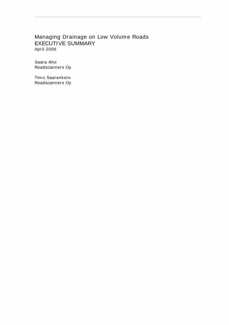
Saara Aho, Timo Saarenketo
MANAGING DRAINAGE ON LOW VOLUME ROADS Executive Summary
Managing Drainage on Low Volume Roads EXECUTIVE SUMMARY April 2006
Saara Aho Roadscanners Oy Timo Saarenketo Roadscanners Oy

PREFACE
The report that follows is an executive summary of the 2005 ROADEX II report “Drainage on Low Traffic Volume Roads – Problem description, improvement techniques and life cycle costs” by Geir Berntsen from Norwegian Road Administration and Timo Saarenketo of Roadscanners Oy, Finland.
It aims to be a working manual, concentrating on the drainage problem classification, monitoring methods, describing the effect of the poor drainage to pavement performance, drainage improvement techniques and their life cycle costs.
The report is not intended to replace any text books or guidelines and specifications available on the subject but it is hoped that the summaries that are outlined will give the reader a greater understanding of the issues and solutions end especially the importance of this problem many times neglected.
The report was written by Saara Aho and Timo Saarenketo from Roadscanners Oy, Finland. Ron Munro, project manager of the ROADEX III Project, checked the language. Mika Pyhähuhta of Laboratorio Uleåborg designed the report layout.
The authors would like to thank the ROADEX III Steering Committee for its encouragement and guidance in this work.
Copyright © 2006 Roadex III Project
All rights reserved.
ROADEX III Lead Partner: The Swedish Road Administration, Northern Region, Box 809, S-971 25 Luleå. Project co-ordinator: Mr. Krister Palo.
CONTENTS
PREFACE................................................................................................................................................3
CHAPTER 1. INTRODUCTION ..............................................................................................................6
1.1 ROADEX -PROJECT ..........................................................................................................................6
1.2 DRAINAGE ON LOW VOLUME ROADS – TIMO KIRJOITTAA............................................7
CHAPTER 2. MONITORING DRAINAGE CONDITION....................................................................8
2.1 MONITORING PROCESS ..............................................................................................................8
2.2 IDENTIFYING THE PROBLEM SECTIONS...............................................................................8
2.3 BASIC DIAGNOSIS OF DRAINAGE PROBLEM SITES..........................................................10
CHAPTER 3. DRAINAGE PROBLEM SITE CLASSIFICATION AND THEIR SOLUTIONS ....11
3.1 GENERAL .......................................................................................................................................11
3.2 MAINTENANCE RELATED PROBLEMS .................................................................................12 3.2.1 Problems Caused by Melting Snow .....................................................................................12 3.2.2 Poorly Working Drainage Structures ...................................................................................13
3.3 DESIGN RELATED PROBLEMS ................................................................................................17 3.3.1 General .................................................................................................................................17 3.3.2 Sloping Ground ....................................................................................................................17 3.3.3 Drainage Problems on “Low Ground” .................................................................................18 3.3.4 Drainage Problems on Flat Area ..........................................................................................19 3.3.5 Drainage Problems on Areas Where the Road is Constructed in Bedrock Cuttings ............19
3.4 OTHER PROBLEMS .....................................................................................................................20 3.4.1 Moisture Trap.......................................................................................................................20 3.4.2 Stability Problems in the Outer Slope ..................................................................................21
CHAPTER 4. EFFECT OF POOR DRAINAGE ON PAVEMENT PERFORMANCE....................22
4.1 GENERAL .......................................................................................................................................22
4.2 THEORETICAL CALCULATIONS ............................................................................................22
4.3 FIELD OBSERVATIONS ..............................................................................................................23
Roadex III The Northern Pheriphery Research
4.4 EFFECT OF POOR DRAINAGE - SUMMARY..........................................................................27
CHAPTER 5. DRAINAGE AND LCC....................................................................................................28
5.1 GENERAL...........................................................................................................................................28
5.2 HOW OFTEN DRAINAGE CAN BE PROFITABLY IMPROVED? ........................................28
CHAPTER 6. CONCLUSIONS AND RECOMMENDATIONS..........................................................30
CHAPTER 7. REFERENCES .................................................................................................................31
APPENDIX 1 .............................................................................................................................................33
TABLE FOR RECOGNISING DRAINAGE PROBLEMS AND PROPOSALS FOR SOLUTIONS .........................................................................................................................................33

Chapter 1. Introduction Page 6
Roadex III The Northern Pheriphery Research
Chapter 1. Introduction
1.1 ROADEX -PROJECT The ROADEX Project is a technical co-operation between roads organisations across northern Europe that aims to share roads related information and research between the partners.
The Project was started in 1998 as a 3 year pilot co-operation between the roads districts of Finnish Lapland, Troms County of Norway, the Northern Region of Sweden and The Highland Council of Scotland and this was later followed up with a second project, ROADEX II, from 2002 to 2005.
The partners in the ROADEX II Project comprised public road administrations, forestry organizations, forest companies and haulage organizations from regions in the Northern Periphery. These were The Highland Council, Forest Enterprise & The Western Isles Council from Scotland. The Region Nord of The Norwegian Public Roads Administration and The Norwegian Road Haulage Association, The Northern Region of The Swedish Road Administration and The Lappi and Keski-Suomi Regions of The Finnish National Roads Administration. (These latter Finnish Regions also received aid from their local forest industry organisations of Metsähallitus, Lapin Metsäkeskus, Metsäliitto & Stora-Enso.)
The goal of the project was to develop ways for interactive and innovative road condition management of low traffic volume roads integrating the needs of local industry, society and roads organisations. 8 formal reports were published together with a project DVD and full copies of all reports are available for download at the ROADEX web site at www.roadex.org.
This Executive Summary report is one of 8 summaries that have been prepared under the direction of the ROADEX III project (2006-2007), a new Project where the named project Partners above were joined by the additional Northern Periphery Partners of the Municipality of Sisimiut, Greenland, The Iceland Public Roads Administration and the Finnish Road Administration Region of Savo-Karjala.
Figure 1: The Northern Periphery Area and Roadex II partners

Chapter 1. Introduction Page 7
Roadex III The Northern Pheriphery Research
1.2 DRAINAGE ON LOW VOLUME ROADS
Water has a key role when discussing the mechanical performance and lifetime of any traffic infrastructure. The fact, known for centuries, is that as long as road structures and subgrade soil do not have excess water the road will work well. But increased water content reduces the bearing capacity of a soil, which will increase the rate of deterioration and shorten the lifetime of the road. In such cases, the road will need rehabilitation more often than a well-drained road structure. When selecting maintenance strategies the paving costs in the maintenance of the road surface need to be compared with the costs of maintaining or improving the drainage. This analysis very challenging in the Northern Periphery because the problem is more complex in cold areas since the freeze-thaw cycles affect moisture content to a much greater extent than elsewhere.
In the ROADEX pilot project 1998-2001 drainage problems were identified to be one of the greatest problems shared by all of the ROADEX partner Road regions. Funding for road condition management has been decreasing in all of the countries participating in the ROADEX project for several years and as a result basic drainage maintenance tasks, such as ditch and culvert cleaning, as well as tasks related to the drainage system in general are neglected since they are considered low on the list of priorities. Instead of drainage maintenance the prioritised tasks have been those that are more important to the road user in the short term i.e. repaving and snow removal.
This report concentrates on presenting the problems that inadequate drainage causes for low volume roads in the NP area of Europe. It also discusses the monitoring methods that can be used when evaluating the drainage condition and proposes possible improvement techniques for different drainage problems. In addition, the effects of drainage on the pavement lifetime and life cycle costs of the pavement structure are studied as a part of the report. The report is mainly based on the research work done during the ROADEX II subproject “Drainage on Low Traffic Volume Roads” written by Berntsen & Saarenketo (2005). The original report contains an extensive literature review on the moisture content in the road structure together with the relationship between moisture content and the characteristics of unbound granular materials and subgrade soils.
Chapter 2. Monitoring Drainage Condition Page 8
Roadex III The Northern Pheriphery Research
Chapter 2. Monitoring Drainage Condition
2.1 MONITORING PROCESS Economic drainage maintenance requires a management system with a systematic approach to monitoring and analysing drainage. This system needs a small investment to be made during its early years to establish the necessary databases but this will quickly be repaid in more effective maintenance thereafter. Monitoring in these early years should be carried out at quite short intervals in order to locate those road sections where drainage performance deteriorates quickly. Once the basic data has been collected and stored in appropriate databases, it is recommended that a comprehensive drainage condition evaluation is carried out at the end of each maintenance contract period or a maximum of 6 - 8 year intervals. During this evaluation the problematic drainage sections should be identified and the need for improvement defined. Once this has been done the particular reasons for the drainage problems can be evaluated and solutions determined for them. This drainage monitoring and improvement strategy can be defined in three phases:
1. mapping the road sections suffering from inadequate drainage 2. making a basic diagnosis of the drainage problem sites 3. defining the solutions for the problem sites
Working through the steps requires information on the condition of the drainage system, its structures, geological conditions etc. For this task methods such as visual inspection of ditches and culverts, interviews of road users and/or maintenance crews, rutting and roughness history analysis and GPR, can be used. In the future new survey techniques, such as laser scanners and thermal cameras, may also be used to monitor drainage condition.
The timing of these phases is very important in order to obtain useful data. The first phase should be done in early spring or in late autumn when the ditches are free of luxuriant vegetation. The spring is the best execution time for the second phase as there is a great amount of melting water flowing around at that time, but it can also be done in summer if necessary.
2.2 IDENTIFYING THE PROBLEM SECTIONS The visual inspection technique is probably the most useful method for identifying road sections suffering inadequate drainage. It is recommended that this visual inspection is done using data loggers supplemented by digital video or series of still
Chapter 2. Monitoring Drainage Condition Page 9
Roadex III The Northern Pheriphery Research
photos from the both sides of the road. This allows all data to be calibrated to similar standards across the years and permit, usage of the data in future, for example, if doing the special design for drainage system.
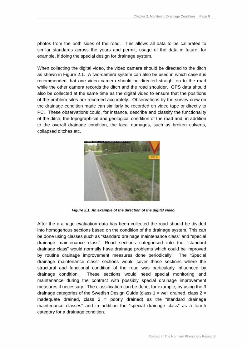
When collecting the digital video, the video camera should be directed to the ditch as shown in Figure 2.1. A two-camera system can also be used in which case it is recommended that one video camera should be directed straight on to the road while the other camera records the ditch and the road shoulder. GPS data should also be collected at the same time as the digital video to ensure that the positions of the problem sites are recorded accurately. Observations by the survey crew on the drainage condition made can similarly be recorded on video tape or directly to PC. These observations could, for instance, describe and classify the functionality of the ditch, the topographical and geological condition of the road and, in addition to the overall drainage condition, the local damages, such as broken culverts, collapsed ditches etc.
Figure 2.1. An example of the direction of the digital video. After the drainage evaluation data has been collected the road should be divided into homogenous sections based on the condition of the drainage system. This can be done using classes such as “standard drainage maintenance class” and “special drainage maintenance class”. Road sections categorised into the “standard drainage class” would normally have drainage problems which could be improved by routine drainage improvement measures done periodically. The “Special drainage maintenance class” sections would cover those sections where the structural and functional condition of the road was particularly influenced by drainage condition. These sections would need special monitoring and maintenance during the contract with possibly special drainage improvement measures if necessary. The classification can be done, for example, by using the 3 drainage categories of the Swedish Design Guide (class 1 = well drained, class 2 = inadequate drained, class 3 = poorly drained) as the “standard drainage maintenance classes” and in addition the “special drainage class” as a fourth category for a drainage condition.
Chapter 2. Monitoring Drainage Condition Page 10
Roadex III The Northern Pheriphery Research
For the detailed analysis in the office, it is recommended that the video or still photo data is analysed along with any rutting and roughness history data, if available. Information from the local maintenance crew can also be used to help identify and classify the problem sections. With rutting information, for instance, the rut depth increase per year can be calculated to find out if poor drainage is having an effect in accelerating rutting rates.
Based on the results of the drainage analysis, problem sections and sections with greater potential to become problematic in the near future can be identified for further analysis. Once this has been done the identified problem sections can be given a detailed problem diagnosis in order to find out the causes for their problems.
A disadvantage of the visual inspection is that it is based on visual evaluation and thus is subjective. If done by a trained crew however, the quality of the drainage class evaluation will be improved. The concept of the drainage analysis and the “special drainage class” will be developed further during the ROADEX III subproject “Drainage guidelines”.
2.3 BASIC DIAGNOSIS OF DRAINAGE PROBLEM SITES If it is decided to proceed with a repair to a problem section of road, the reason for the underlying problems should be identified. This basic diagnosis should include the evaluation of whether the drainage problems are related to poorly working drainage structures, to the location of the road and its surroundings, or if there is the moisture trap in a road structure, or if there are stability problems in outer slopes of the road (see Figure 3.1).
This basic diagnosis will usually require a more accurate visual inspection, which means that the condition of the culverts and other existing drainage structures, such as outlet ditches, are inspected on foot. Also GPR data, if available, may be helpful for finding out the reason for the existing damages. This may be, for instance, that bedrock is blocking the water in the road structure and so preventing the drainage system to work properly.
It is important that the personnel executing this work have an adequate knowledge to recognise the causes for the problems and to make a proposal for the repair measures needed. The detailed site visit can also identify any additional surveys that are needed in order to make the diagnosis.

Chapter 3. Drainage Problem Site Classification and Their Solutions Page 11
Roadex III The Northern Pheriphery Research
Chapter 3. Drainage Problem Site Classification and Their Solutions
3.1 GENERAL Even though the ground conditions, landscape and climate vary much throughout the NP-area, the drainage problems encountered are basically the same. A small exception has been Scotland where there are some special problems related to the use of grass verges. The problems can be grouped in three main categories as shown in Figure 3.1.
Figure 3.1. Category of drainage problems. The drainage problems presented in Figure 3.1 are described in the following text by:
• problem description
• how to recognize the problem
• what causes the problem
• estimates for how to improve the drainage
A summary table of the drainage problems, including guidelines for how to recognise the problems and proposals for suitable improvement techniques, is given in Appendix 1. In addition, more detailed descriptions of the drainage problems listed are presented in ROADEX II project phase II report “Drainage on Low Traffic Volume Roads” written by Berntsen & Saarenketo (2005).

Chapter 3. Drainage Problem Site Classification and Their Solutions Page 12
Roadex III The Northern Pheriphery Research
3.2 MAINTENANCE RELATED PROBLEMS
3.2.1 Problems Caused by Melting Snow During thawing periods there can be great amount of water from melted snow and rainfall on road surfaces and in the ditches. The main problem is that most frozen soils are almost impermeable in comparison to non-frozen soils. Additionally the melt water and rainwater cannot drain because the ditches are filled with snow and ice and, as such, do not function. In these circumstances excess water from the ice lenses has only one path through which to drain, that being upwards through the road structure, which together with the surface water causes excess pore water pressure within the road structure. This will reduce bearing capacity during these periods. Typical drainage problems during spring thaw are described in Figure 3.2.
Figure 3.2. Drainage problems during spring thaw. Improvement techniques - suggestions:
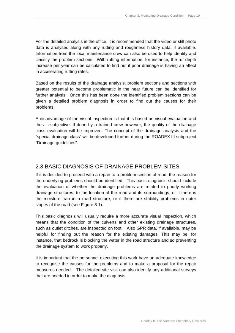
• snow can be cleared from the ditches during the thawing periods to remove the surface water (Figure 3.3)
• use of deep drainage
• frost insulation (expensive)
• raising the grade line of the carriageway (new structures) and/or make wider and deeper ditches
• use materials in the road structure that are not susceptible to water or frost
• when designing a road structure, the bearing capacity of the subgrade soils during the critical spring thaw period must be considered
Chapter 3. Drainage Problem Site Classification and Their Solutions Page 13
Roadex III The Northern Pheriphery Research
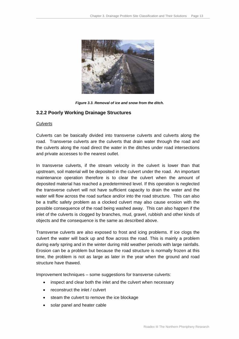
Figure 3.3. Removal of ice and snow from the ditch.
3.2.2 Poorly Working Drainage Structures
Culverts
Culverts can be basically divided into transverse culverts and culverts along the road. Transverse culverts are the culverts that drain water through the road and the culverts along the road direct the water in the ditches under road intersections and private accesses to the nearest outlet.
In transverse culverts, if the stream velocity in the culvert is lower than that upstream, soil material will be deposited in the culvert under the road. An important maintenance operation therefore is to clear the culvert when the amount of deposited material has reached a predetermined level. If this operation is neglected the transverse culvert will not have sufficient capacity to drain the water and the water will flow across the road surface and/or into the road structure. This can also be a traffic safety problem as a clocked culvert may also cause erosion with the possible consequence of the road being washed away. This can also happen if the inlet of the culverts is clogged by branches, mud, gravel, rubbish and other kinds of objects and the consequence is the same as described above.
Transverse culverts are also exposed to frost and icing problems. If ice clogs the culvert the water will back up and flow across the road. This is mainly a problem during early spring and in the winter during mild weather periods with large rainfalls. Erosion can be a problem but because the road structure is normally frozen at this time, the problem is not as large as later in the year when the ground and road structure have thawed.
Improvement techniques – some suggestions for transverse culverts:
• inspect and clear both the inlet and the culvert when necessary
• reconstruct the inlet / culvert
• steam the culvert to remove the ice blockage
• solar panel and heater cable
Chapter 3. Drainage Problem Site Classification and Their Solutions Page 14
Roadex III The Northern Pheriphery Research
Culverts that are installed along the road have normally a smaller diameter than transverse culverts under roads. Culverts across private accesses are normally placed at the bottom of the ditch, which is often shallow compared to the culvert across the road. Many times, because of the lower flow velocity, fine material is easily deposited in the culvert and this reduces the effective drainage area. Another problem is that the shallow placement, low flow velocity and limited drainage area make the culvert susceptible to frost and icing. Ice can clog culverts and the problem can be severe during the spring thaw when the snow melts and the need for an effective solution is urgent.
Special cases in drainage and access are shops, petrol stations and other business where culverts along the road are often very long. In these sections culverts are more exposed to frost and ice and also more difficult to cleared of fine soils and rubbish.
Improvement techniques – suggestions for culverts along the roads:
• clear the culvert regularly
• in spring, steam the culvert to remove the ice blockage
• use solar panel and heater cable for icing
• for difficult problems there may be a need to replace the drainage system with deep drainage and an outlet basin with a sand trap
With differential frost heave, settlements or faulty construction, culverts may crack and deteriorate. The consequence of this is that water will flow uncontrolled and may cause erosion around the culvert and/or raise the ground water table. In such cases after heavy rains the road structure can be washed away and result in the road being closed.
Improvement techniques – suggestions:
• replace the damaged the culvert and make a frost free foundation
• reline the culvert using a PEH pipe installed inside the old culvert and inject concrete between the two pipes
Ditches
Ditch capacity can be reduced by accumulations of mud and vegetation filling up the bottom of the ditch over a period of years and this will reduce the drainage capacity. The consequence of this is that the ground water table rises in the road structure and the bearing capacity is reduced. In areas where the subgrade soil is fine graded, the need for ditch clearing is greater as the fine soils can be easily eroded. The stability of ditch slope can also be a difficult problem especially in silty areas as can be seen in Figure 3.5. Collapsed ditches should always be opened or a strengthening structure be put in place.

Chapter 3. Drainage Problem Site Classification and Their Solutions Page 15
Roadex III The Northern Pheriphery Research
Figure 3.5. The collapsed road shoulder in silty area. The shot was taken during first spring after ditch cleaning.
Clear outlet ditches are very important for the well working of a drainage system and these should not be ignored when inspecting ditches as part of a drainage system. There is little benefit in clearing the ditches along the road if the effective outlet for the drained water is not available. Thus, whenever ditches are being repaired, outlet ditches should receive similar treatment. Basically, the same improvement techniques (listed below) can be used both for outlet ditches and for ditches along the road.
Improvement techniques ditches – suggestions:
• clearing the ditches often enough
• erosion protection, exchange the material in outer slope of the ditch using coarse aggregate and geotextile (Figure 3.6)
• “piping the ditch” (subsurface drain)
• ditch trenches filled with coarse material wrapped in geotextile
Figure 3.6. Protection of outer slope of a ditch.

Chapter 3. Drainage Problem Site Classification and Their Solutions Page 16
Roadex III The Northern Pheriphery Research
Grass verges
High grass verges are a major problem in Scotland on the old, narrow rural road networks but similar kinds of problem can arise in the other NP areas also when the turf on the road shoulder grows to a level higher than the adjacent asphalt surface. Where this happens the surface water is forced to drain through the pavement structure instead of flowing normally to ditches. This results in reduced bearing capacity and deformations.
Improvement techniques – suggestions:
• remove the verges and turfs, make ditches to drain surface water and pavement structure
• deep drainage (subdrain)
• edge drainage
Poor cross fall
A good cross fall is a major factor in how fast water will drain from the road surface. Road drainage depends both on the transverse cross fall and the slope of the road. For a cross fall to be considered effective on paved roads in Norway it must be at least 1 %. In Finland the recommended cross fall for gravel roads is 4 %.
Ruts and uneven road surfaces can prevent surface water from draining quickly and any standing surface water on the road can infiltrate the road structure. The amount of infiltration will depends on the number of cracks, potholes and the permeability of the pavement.
Water on the road surface can also be a traffic safety problem. A wet surface reduces friction which leads to longer braking distance. Surface water can also freeze during frosty nights and the roads become very slippery. Also a sudden change in friction may come as a surprise for drivers. For this reason it is important that all roads have sufficient cross falls and these can be obtained through rehabilitation or resurfacing of road.
Cracks and potholes
Most low traffic volumes roads in Sweden, Finland and Norway have a very thin asphalt surface layer with a crushed gravel base course. This type of base course can have a high fines content and low stiffness compared to other base materials and this can cause large horizontal stresses in the asphalt surface layer. If the bitumen in the surface layer is stiff this will result in alligator and longitudinal cracking. Additional cracking caused by frost heave, weak edges and heavy wheel loads is also common.

Chapter 3. Drainage Problem Site Classification and Their Solutions Page 17
Roadex III The Northern Pheriphery Research
The road surface is often uneven on these roads and any surface water can be concentrated in ruts and other recesses. If the surface is also cracked in these locations, the trapped surface water will penetrate into the gravel course and reduce the bearing capacity of the material. This will accelerate the deterioration of the road.
To handle this problem, flexible bitumen bound materials should be used in the surface layer and, as such, a soft bitumen is recommended. It is also important to seal the surface so that the water will flow into the ditches and not into the road structure as already discussed.
3.3 DESIGN RELATED PROBLEMS
3.3.1 General A drainage system can still be insufficient even if the system has been constructed according to the guidelines. Guidelines cannot cover all eventualities and if it is evident that the problems are caused by moisture in the road structure there is still a need to improve the drainage system.
3.3.2 Sloping Ground In the greater part of the NP-area the roads are constructed on sloping ground where one half of the road is situated in a cutting and the other half of the road is situated on an embankment as shown in Figure 3.7. Drainage problems related to sloping ground are normally found in areas with moraine and sand/silt materials. Where the subgrade soil is clay or peat, the terrain is normally flat.
Figure 3.7. Drainage problem on sidelong road.
In roads on sloping ground the ground water table will normally be nearer to the road surface (and to the wheel load) on the road cut side. Moisture content is a function of its distance from the ground water table and thus the rut deformation in the hillside wheel track is greater on sloping ground. The consequence of this is that the road cut side triggers the need for rehabilitation many years earlier than the

Chapter 3. Drainage Problem Site Classification and Their Solutions Page 18
Roadex III The Northern Pheriphery Research
well-drained embankment side. The lifetime ratio (drained lane / undrained lane) may be more than 2.
On sloping ground the ground water naturally flows under the road. If there is bedrock or impermeable materials close to the road, these objects may block or concentrate the ground water in places where there is a high potential for developing frost heaves, spring thaw softening and reduced bearing capacity.
Improvement techniques – suggestions:
• increase the thickness of the road structure (soil replacement) on the road cut side or raise the grade line of the carriageway
• use a subdrain to lower the ground water table on the road cut side
• edge drainage
• remove bedrock/impermeable materials that block the ground water flow
• frost insulation (expensive)
• the use of additional culverts in places the water is being blocked
3.3.3 Drainage Problems on “Low Ground” In areas of low ground, where there is not a natural drainage system for surface water, excess surface water has to infiltrate the subgrade soil. When the ground is frozen or after period of heavy rainfall or snow melt, this water cannot quickly escape and collects in low lying areas until it rises sufficiently to flood the road. This causes problems for the road as shown in the picture in Figure 3.8. Also, especially on gravel roads, the raised ground water table can soften the road structure and the road surface to the extent that the road becomes impassable.
Figure 3.8. Drainage problem on low lying ground, Rd 19778, Kemijärvi, Finland.

Chapter 3. Drainage Problem Site Classification and Their Solutions Page 19
Roadex III The Northern Pheriphery Research
Improvement techniques – suggestions: Moraine subgrade
• it is possible to make infiltration wells or infiltration ditches
• raise the grade line of the carriageway (also helps winter maintenance)
Clay, silt or peat subgrade
• raise the grade line of the carriageway (also helps winter maintenance), but be aware of possible stability problems
• infiltration is not possible
3.3.4 Drainage Problems on Flat Areas Drainage problems of roads crossing flat areas are usually similar to those of roads located on low-lying ground, with the added difficulties of dealing with long distances to the natural drainage system and getting rid of the water. This problem is most apparent during the spring thaw when the ground is still frozen and there is a great amount of water from melted snow and rainwater. This also happens during periods of heavy rainfall where the subgrade soil may have problems draining the surface water. The extent of the problem depends on the amount of water and the permeability of the subgrade soil. In any case, the effect will be the same. The ground water table will rise and the consequences are described in the previous section.
Improvement techniques – suggestions: Moraine subgrade
• raise the grade line of the carriageway
• replace road materials with non frost and water susceptible materials
• making infiltration wells or ditch
• making long ditches (long outlet ditches) or deep drainage
Clay, silt or peat subgrade
• raise the grade line of the carriageway – (watch for possible settlements)
• long ditches (long outlet ditches) (surface or subdrain)
• infiltration well technique is not possible
3.3.5 Drainage Problems Related to the Presence of Bedrock The presence of bedrock close to the grade line always makes a special problem for road drainage especially when road is located on a sloping ground. Bedrock can block ground water flows and this can be one reason why road structures will not drain causing a reduced bearing capacity. During the frost season road structures can freeze down to the bedrock surface blocking the ground water flow. This causes ice lenses to form on top of the bedrock leading to uneven bumps in
Chapter 3. Drainage Problem Site Classification and Their Solutions Page 20
Roadex III The Northern Pheriphery Research
the road surface. It is also possible that depressions in the bedrock surface can collect water and if there are frost susceptible materials in the road structure segregation ice will form.
Improvement techniques – suggestions:
• blast the bedrock to a depth of 1-2 m below foundation. This will create cracks in the bedrock and the water will be able to drain from the road structure
• provide ditches/deep drainage that prevent the water from entering the road structure
• use frost insulation (should be especially considered on sloping ground where bedrock blasting is not possible, or is expensive)
• remove or drain basins or bowls in the bedrock that are collecting water
3.4 OTHER PROBLEMS
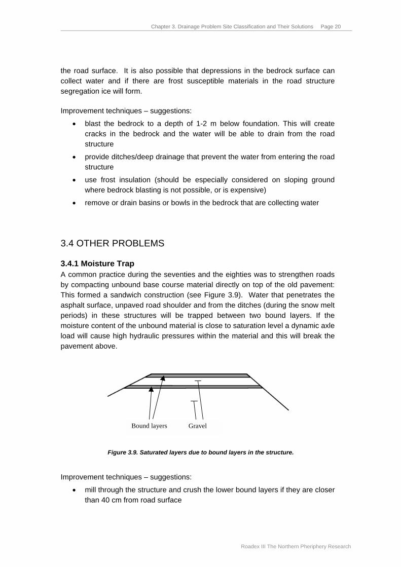
3.4.1 Moisture Trap A common practice during the seventies and the eighties was to strengthen roads by compacting unbound base course material directly on top of the old pavement: This formed a sandwich construction (see Figure 3.9). Water that penetrates the asphalt surface, unpaved road shoulder and from the ditches (during the snow melt periods) in these structures will be trapped between two bound layers. If the moisture content of the unbound material is close to saturation level a dynamic axle load will cause high hydraulic pressures within the material and this will break the pavement above.
Bound layers Gravel
Figure 3.9. Saturated layers due to bound layers in the structure.
Improvement techniques – suggestions:
• mill through the structure and crush the lower bound layers if they are closer than 40 cm from road surface
Chapter 3. Drainage Problem Site Classification and Their Solutions Page 21
Roadex III The Northern Pheriphery Research
• mill existing pavement and increase the thickness of the unbound layers to be at least 35 cm (plus 5 cm of pavement)
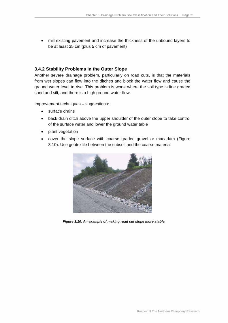
3.4.2 Stability Problems in the Outer Slope Another severe drainage problem, particularly on road cuts, is that the materials from wet slopes can flow into the ditches and block the water flow and cause the ground water level to rise. This problem is worst where the soil type is fine graded sand and silt, and there is a high ground water flow.
Improvement techniques – suggestions:
• surface drains
• back drain ditch above the upper shoulder of the outer slope to take control of the surface water and lower the ground water table
• plant vegetation
• cover the slope surface with coarse graded gravel or macadam (Figure 3.10). Use geotextile between the subsoil and the coarse material
Figure 3.10. An example of making road cut slope more stable.
Chapter 4. Effect of Poor Drainage on Pavement Performance Page 22
Roadex III The Northern Pheriphery Research
Chapter 4. Effect of Poor Drainage on Pavement Performance
4.1 GENERAL Many models have been developed to evaluate road structure performance under traffic loads. Some of them calculate, or at least take into account, the effect of drainage. The problem with these models is the complex mechanisms on how the water content affects the pavement performance. These mechanisms need to be simplified when predicting the deterioration of a road section as a function of drainage quality.
Almost every researcher mentions in their studies that drainage is the most important parameter when considering long-term serviceability of the road structure. However, very few studies have investigated to what extent good drainage really affects the lifetime of a road structure. Some of the better known design procedures are used in the following sections to evaluate the lifetime of a road structure with varying water content. In addition to these procedures, field observations are also presented to demonstrate the effect of poor drainage to pavement life time.
4.2 THEORETICAL CALCULATIONS The following guidelines, containing models that consider the effect of drainage quality, were presented in the initial ROADEX II report:
• Swedish design guide
• AASHTO design guide
• HDM-4
• FHWA, LTPP programme in SHRP Further models, presented in the literature review, were also used to calculate the effect of drainage on the deformation of the subgrade.
The Swedish design guide classifies the resilient modulus of poor quality materials (outside the specification) into 3 categories based on their drainage analysis results. These materials are often present on low volume roads. From these values it is possible to calculate the effect of improvement of the drainage class of a road section to a better class by using the calculated stresses and strains in suitable deterioration models.

Chapter 4. Effect of Poor Drainage on Pavement Performance Page 23
Roadex III The Northern Pheriphery Research
In the initial report (Berntsen and Saarenketo 2005) two examples were presented to demonstrate the effect of different drainage classes. The calculations were made by Swedish Road Administration’s PMS Object software which uses a linear elastic model. As a result the number of standard axles was calculated until the maximum permanent deformation and fatigue cracking permitted occurred. The results showed that the lifetime of the road structure were increased by a factor of 2.2 – 2.6 when the drainage system was improved from poor to appropriate condition (from drainage class 3 to 1). The subgrade soil was considered to be moraine but if it had been silt the ratio would have been even larger.
The AASHTO design guide uses 5 different classes for drainage quality ranging from “very poor” to “excellent”. Improving the drainage quality from “very poor” to “fair” under these guidelines shows a much larger increase in lifetime than with the Swedish model. The lifetime multiplies 5 times in the examples presented in the initial report.
The deterioration models developed in the SHRP programme are based on multiple regressions of condition development from a large range of potential parameters and have through regression analyses quantified the importance of moisture content. The SHRP models are not easy to adopt but it is clear that the models give increased deterioration when the moisture content increases and that the differences are larger when there is frost present.
An increase in pavement lifetime can also be achieved by increasing the subbase thickness. An increase in subbase layer of 8 cm will have the same effect as lowering the ground water table by 40 cm (from the level of 20 cm above the foundation to the level of 20 cm below the foundation). This of course cannot be done on an old road, but it is important to be aware of when designing a road structure and drainage system. There are places where it is difficult to provide sufficient drainage and the best solution can be by increasing the road structure thickness, ie. raising the grade line compared to ground water table.
4.3 FIELD OBSERVATIONS The effect of poor drainage on pavement performance can be seen in practice by observing road sections constructed on sloping ground. As described in Chapter 3.3.2 the ground water table is normally nearer to the road surface (and, as such, to the wheel load) on the road cut side. On the embankment side of the road the distance to the ground water table is greater and the moisture content of the road structure smaller. Thus, the road cut side can be used to demonstrate the situation of poor drainage system and the embankment side to demonstrate the situation of drainage system in good condition. Approximately the same conditions have been found in pavement structures situated in cuttings: the moisture content in these
Chapter 4. Effect of Poor Drainage on Pavement Performance Page 24
Roadex III The Northern Pheriphery Research
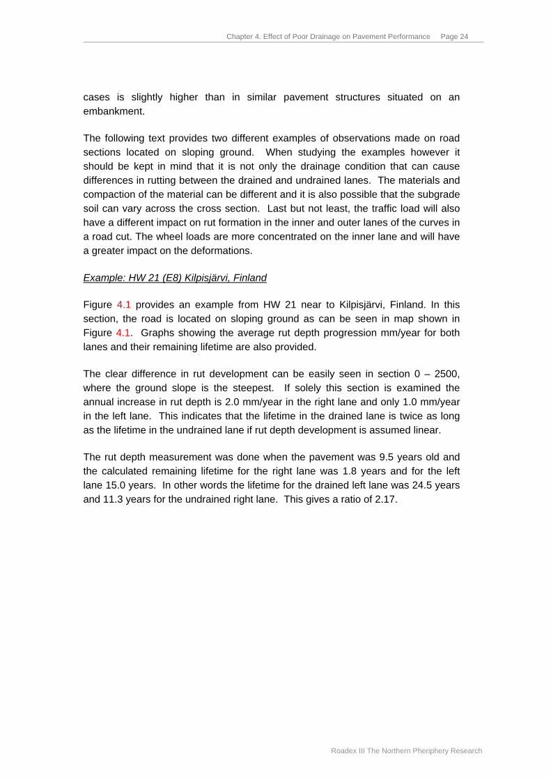
cases is slightly higher than in similar pavement structures situated on an embankment.
The following text provides two different examples of observations made on road sections located on sloping ground. When studying the examples however it should be kept in mind that it is not only the drainage condition that can cause differences in rutting between the drained and undrained lanes. The materials and compaction of the material can be different and it is also possible that the subgrade soil can vary across the cross section. Last but not least, the traffic load will also have a different impact on rut formation in the inner and outer lanes of the curves in a road cut. The wheel loads are more concentrated on the inner lane and will have a greater impact on the deformations.
Example: HW 21 (E8) Kilpisjärvi, Finland
Figure 4.1 provides an example from HW 21 near to Kilpisjärvi, Finland. In this section, the road is located on sloping ground as can be seen in map shown in Figure 4.1. Graphs showing the average rut depth progression mm/year for both lanes and their remaining lifetime are also provided.
The clear difference in rut development can be easily seen in section 0 – 2500, where the ground slope is the steepest. If solely this section is examined the annual increase in rut depth is 2.0 mm/year in the right lane and only 1.0 mm/year in the left lane. This indicates that the lifetime in the drained lane is twice as long as the lifetime in the undrained lane if rut depth development is assumed linear.
The rut depth measurement was done when the pavement was 9.5 years old and the calculated remaining lifetime for the right lane was 1.8 years and for the left lane 15.0 years. In other words the lifetime for the drained left lane was 24.5 years and 11.3 years for the undrained right lane. This gives a ratio of 2.17.

Chapter 4. Effect of Poor Drainage on Pavement Performance Page 25
Roadex III The Northern Pheriphery Research
Figure 4.1. Road section on HW21 – Kilpisjärvi, Finland, showing average rut increase / year and remaining lifetime.
Example: Field observations from 184 km of roads in Troms county, Norway
In Norway, rut depths are measured every year on both sides of all paved national and county roads. The roads are divided into homogeneous sections where the condition is almost the same. These sections are used in the Norwegian PM System. For each section, the statistical distribution of rutting is calculated and the rut value describing the level where 90 % of the road section has lesser ruts is defined. This rut value is then used as a damage trigger factor and when this
HW21, section 220 Rut increase / year
0
0.5
1
1.5
2
2.5
3
3.5
4
4.5
5
0 1000 2000 3000 4000 5000 6000 (m)
Rut
incr
ease
(mm
/yea
r)
RUT__INC_right RUT__INC_left
HW21 Section 220 Rutting Analysis Paving date 1992, Measured 2001, Critical value: 25 mm/50m
0
10
20
30
40
50
60
0 500 1000 1500 2000 2500 3000 3500 4000 4500 5000 5500 6000 (m)
Year
s le
ft fo
r new
ove
rlay
Years_Left_right Years_Left_left
Chapter 4. Effect of Poor Drainage on Pavement Performance Page 26
Roadex III The Northern Pheriphery Research
exceeds 25 mm the guidelines recommend that the road surface should be improved.
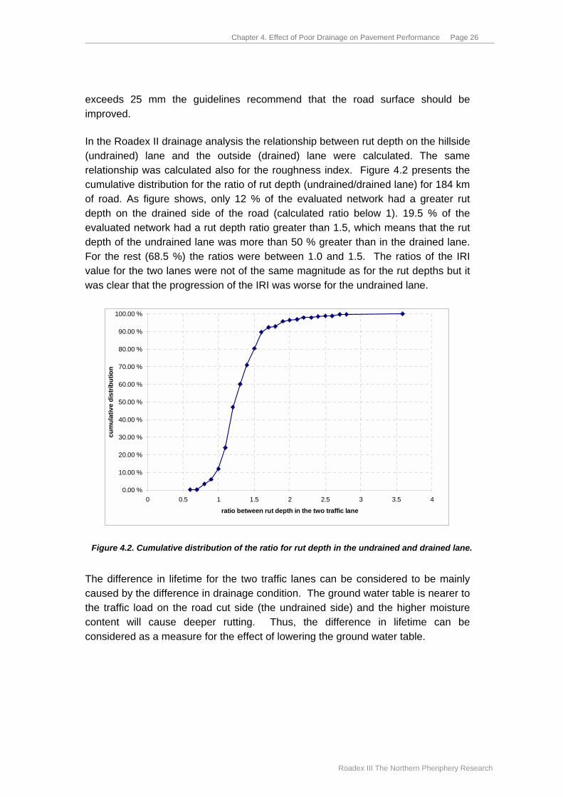
In the Roadex II drainage analysis the relationship between rut depth on the hillside (undrained) lane and the outside (drained) lane were calculated. The same relationship was calculated also for the roughness index. Figure 4.2 presents the cumulative distribution for the ratio of rut depth (undrained/drained lane) for 184 km of road. As figure shows, only 12 % of the evaluated network had a greater rut depth on the drained side of the road (calculated ratio below 1). 19.5 % of the evaluated network had a rut depth ratio greater than 1.5, which means that the rut depth of the undrained lane was more than 50 % greater than in the drained lane. For the rest (68.5 %) the ratios were between 1.0 and 1.5. The ratios of the IRI value for the two lanes were not of the same magnitude as for the rut depths but it was clear that the progression of the IRI was worse for the undrained lane.
0.00 %
10.00 %
20.00 %
30.00 %
40.00 %
50.00 %
60.00 %
70.00 %
80.00 %
90.00 %
100.00 %
0 0.5 1 1.5 2 2.5 3 3.5 4
ratio between rut depth in the two traffic lane
cum
ulat
ive
dist
ribut
ion
Figure 4.2. Cumulative distribution of the ratio for rut depth in the undrained and drained lane. The difference in lifetime for the two traffic lanes can be considered to be mainly caused by the difference in drainage condition. The ground water table is nearer to the traffic load on the road cut side (the undrained side) and the higher moisture content will cause deeper rutting. Thus, the difference in lifetime can be considered as a measure for the effect of lowering the ground water table.
Chapter 4. Effect of Poor Drainage on Pavement Performance Page 27
Roadex III The Northern Pheriphery Research
4.4 EFFECT OF POOR DRAINAGE - SUMMARY The prediction models in Chapter 3 have been used to demonstrate that the lifetime of the pavement structure (calculated as number of standard axles) will increase considerably when drainage is improved. When comparing the results from the Swedish design guide with the field observations, the results were surprisingly similar. All other prediction models produce a similar or even greater effect.
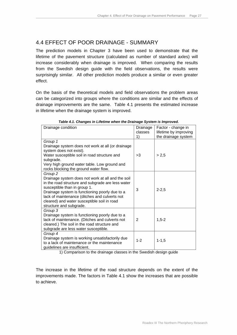
On the basis of the theoretical models and field observations the problem areas can be categorized into groups where the conditions are similar and the effects of drainage improvements are the same. Table 4.1 presents the estimated increase in lifetime when the drainage system is improved.
Table 4.1. Changes in Lifetime when the Drainage System is Improved. Drainage condition Drainage
classes 1)
Factor - change in lifetime by improving the drainage system
Group 1 Drainage system does not work at all (or drainage system does not exist). Water susceptible soil in road structure and subgrade. Very high ground water table. Low ground and rocks blocking the ground water flow.
>3 > 2,5
Group 2 Drainage system does not work at all and the soil in the road structure and subgrade are less water susceptible than in group 1. Drainage system is functioning poorly due to a lack of maintenance (ditches and culverts not cleared) and water susceptible soil in road structure and subgrade.
3 2-2,5
Group 3 Drainage system is functioning poorly due to a lack of maintenance. (Ditches and culverts not cleared.) The soil in the road structure and subgrade are less water susceptible.
2 1,5-2
Group 4 Drainage system is working unsatisfactorily due to a lack of maintenance or the maintenance guidelines are insufficient.
1-2 1-1,5
1) Comparison to the drainage classes in the Swedish design guide
The increase in the lifetime of the road structure depends on the extent of the improvements made. The factors in Table 4.1 show the increases that are possible to achieve.
Chapter 5. Drainage and LCC Page 28
Roadex III The Northern Pheriphery Research
Chapter 5. Drainage and LCC
5.1 GENERAL It is essential to know the maintenance cost of a drainage system to be able to calculate the effect of a well working system on the life cycle costs of a pavement. The actual maintenance costs will vary between the countries in the NP-area, and also within each country.
Normally the cost of maintaining a drainage system is much less than resurfacing and in Norway, for instance, resurfacing a low traffic volume road will cost 8-10 times more than clearing the ditches and culverts (ditch clearing costs 10-12% of the repaving costs, a new pavement costs 32-37 €/metre and ditch clearing 3.7-4.5 €/metre). In Finland, where the LC analysis is also done, the prices are slightly lower but the ratio between ditch cleaning and new pavement is roughly the same.
However a ditch may not always work even though it has been shaped according to the design guidelines. In such cases the drainage has to be improved by increasing the depth of the ditch or by using deep drainage. These improvements are more expensive and the costs depend on the nature of the problem. The cost of installing deep drainage ranges from 30 – 50% of the cost of repaving depending on the type of subgrade soil.
In the following sections a comparison between the costs of repaving of a 5 or 6 metre wide road and the costs of ditch clearing is given. Normally only short parts of long sections deteriorate due to inadequate drainage, but these short parts are the reason why the whole section is repaved. Because of this the relative costs will be further reduced and will make the drainage improvements even more cost effective.
5.2 HOW OFTEN DRAINAGE CAN BE PROFITABLY IMPROVED? An interesting question is often posed: how often can drainage improvement measures be taken while still keeping the life cycle costs profitable. As an example, LCA calculations were made using a drainage improvement cost of 4,100 €/km and a pavement replacement cost 35,000 €/km (ratio 0.117). The results of this analysis can be seen in Figure 5.1.
Figure 5.1 shows that if improving/maintaining the drainage system would double the lifetime (from 10 to 20 years) the drainage maintenance measures can be done

Chapter 5. Drainage and LCC Page 29
Roadex III The Northern Pheriphery Research
every second year and be still profitable even though the discount rate is as high as 8% (as used in Norway). If the increase in lifetime is only by 50 % (from 10 to 15 years) and the discount rate is only 4% (as used in Finland), drainage maintenance can still be done every third year profitably. Normally there is no need for doing drainage maintenance more often than this.
0
1000
2000
3000
4000
5000
6000
Disc 4%, life timeratio 2.0
Disc 4%, life timeratio 1.5
Disc 8%, life timeratio 2.0
Disc 8%, life timeratio 1.5
Life
cyc
le c
ost /
yea
r (€
)
no drainage improvementdrainage life time 3 yearsdrainage life time 5 yearsdrainage life time 7 years
Figure 5.1. Example of life cycle cost analysis results showing the benefits of drainage improvements. Results are presented using two lifetime ratios of 2.0 (10 to 20 years) and 1.5 (10
to 15 years) and using two different discount rates (4 % and 8 %).
The example calculation does not take into account increases in other maintenance costs due poorly working drainage. In fact, the benefits of keeping drainage in good condition should be calculated for longer than one pavement life cycle because frost fatigue, due to high moisture content, will affect the long term performance of the road structures.
The calculations also show that it is always worth considering the use of more expensive drainage improvement solutions than the ditch cleaning alone. For instance, if pavement lifetime can be doubled and the discount rate is 4%, drainage improvement can cost 8,400 €/km and it can be still renewed every 5 years and the life cycle costs would still be less than without drainage renovation.

Chapter 6. Recommendations Page 30
Roadex III The Northern Pheriphery Research
Chapter 6. Recommendations
It has been demonstrated through theoretical models and field observations in this report, that if an inadequate drainage is the reason for low bearing capacity and a short lifetime, then it is possible to increase the lifetime at least by a factor of 1.5 – 2 by improving the drainage. Thus, maintaining the drainage system is perhaps the most profitable maintenance task for road owners in addition to being a sustainable and economical road condition management system. Effective drainage maintenance should therefore be prioritized ahead of any other measures.
The first step in a road strengthening process should be to make the drainage system work properly. This should be done 1-2 years before paving because this ensures that the road structures are well drained and in a better condition for when the rehabilitation starts.
A drainage condition evaluation is recommended to be done always at the end of every maintenance contract period or, at least, every 8th year. During the evaluation the problematic drainage sections should be identified and their need for repair defined. Then the reasons for the problems need to be found and their solutions designed.
During the drainage analysis it is recommended that the road should be divided into homogenous sections based on the condition of the drainage system by using the classes such as “normal drainage class” and “special drainage class”. The drainage problems categorised into the “normal drainage class” can be improved by the routine drainage improvement measures which are done periodically. The “special drainage class” sections will need a special monitoring during the maintenance contract period and their improvement may need more than routine measures and techniques. This concept of the drainage analysis and especially the “special drainage class” will be developed further during the ROADEX III subproject “Drainage guidelines”.

Chapter 7. References Page 31
Roadex III The Northern Pheriphery Research
Chapter 7. References
Aho S., Saarenketo T., Berntsen G., Dawson A., Kolisoja P. and Munro R. (2005). Structural Innovations. ROADEX II report. www.roadex.org
Berntsen G. and Saarenketo T. (2005). Drainage on Low Traffic Volume Roads. ROADEX II report. www.roadex.org
Lary, J.A. and Mahoney, J.P. 1984. Seasonal effects on the strength of pavement structures. Transportation Research Record 954.
Noss, P. M. 1978. Poresug i jordarter (Soil suction). Doctor thesis. Norwegian University of Science and Technology. Trondheim.
Roadex Project 1998-2001. Northern Periphery. CD-ROM
Saarenketo, T. 2005. Monitoring, Communication and Information Systems & Tools for Focusing Actions. ROADEX II report. www.roadex.org
Saarenketo T. and Aho S. (2005). Managing Spring Thaw Weakening on Low Volume Roads. ROADEX II report. www.roadex.org

Appendix 1 Page 33
Roadex III The Northern Pheriphery Research
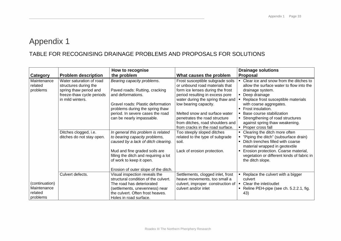
Appendix 1 TABLE FOR RECOGNISING DRAINAGE PROBLEMS AND PROPOSALS FOR SOLUTIONS
Category Problem description
How to recognise the problem What causes the problem
Drainage solutions Proposal
Water saturation of road structures during the spring thaw period and freeze-thaw cycle periods in mild winters.
Bearing capacity problems. Paved roads: Rutting, cracking and deformations. Gravel roads: Plastic deformation problems during the spring thaw period. In severe cases the road can be nearly impassable.
Frost susceptible subgrade soils or unbound road materials that form ice lenses during the frost period resulting in excess pore water during the spring thaw and low bearing capacity. Melted snow and surface water penetrates the road structure from ditches, road shoulders and from cracks in the road surface.
! Clear ice and snow from the ditches to allow the surface water to flow into the drainage system.
! Deep drainage ! Replace frost susceptible materials
with coarse aggregates. ! Frost insulation. ! Base course stabilization ! Strengthening of road structures
against spring thaw weakening. ! Proper cross fall
Ditches clogged, i.e. ditches do not stay open.
In general this problem is related to bearing capacity problems, caused by a lack of ditch clearing. Mud and fine graded soils are filling the ditch and requiring a lot of work to keep it open. Erosion of outer slope of the ditch.
Too steeply sloped ditches related to the type of subgrade soil. Lack of erosion protection.
! Clearing the ditch more often ! ”Piping the ditch” (subsurface drain) ! Ditch trenches filled with coarse
material wrapped in geotextile ! Erosion protection. Coarse material,
vegetation or different kinds of fabric in the ditch slope.
Maintenance related problems (continuation) Maintenance related problems
Culvert defects.
Visual inspection reveals the structural condition of the culvert. The road has deteriorated (settlements, unevenness) near the culvert. Often frost heaves. Holes in road surface.
Settlements, clogged inlet, frost heave movements, too small a culvert, improper construction of culvert and/or inlet
! Replace the culvert with a bigger culvert
! Clear the inlet/outlet ! Reline PEH-pipe (see ch. 5.2.2.1, fig.
43)

Appendix 1 Page 34
Roadex III The Northern Pheriphery Research
Category Problem description
How to recognise the problem What causes the problem
Drainage solutions Proposal
Blocked culvert inlet. Rubbish, branches, turf, mud are blocking the inlet. Problems especially after heavy rains when a great amount of surface water needs to be drained away.
The inlet may be designed incorrectly. Culvert diameter is too small. The area upstream from the culvert is eroded and the materials are deposited in the inlet.
! Clear the inlet. ! Reconstruct the inlet. ! Replace with a bigger culvert
Ice clogging the culverts Ice clogs the culvert and water will flow across the road during mild weather in winter and during snow melting period in spring. Pooling in the upper ditch.
The frost accesses the culvert either through penetrating from above or through the pipe itself. Slow water flow through the culvert. Drainage area is reduced due to lack of clearing.
! Clearing the culvert of sand, gravel etc. will reduce the problem
! Steam to melt the ice ! Reconstruct the culvert (lower it if
possible) and the outlet and inlet. ! Solar panel or wind mill that powers a
heater cable
Turf on the road shoulder Turf on the shoulder grows and blocks surface water from flowing off of the road Traffic safety problem (pooling) in addition to deterioration of the road.
Vegetation that grows on the road shoulder and the inner slope of the ditch will form turf that grows larger every year.
! Remove the turf
Grass verges The pavement is deteriorated at the edge of carriageway and mainly at the lowest points where water remains on the surface during rainfall.
Some roads have grass verges instead of ditches. The surface water is prevented from leaving the pavement and will ingress the road structure.
! Remove the verges and make ditches ! Deep drainage ! Edge drainage ! Surface water must be able to flow
away as soon as possible.
Design related problems
Drainage problems due to the road being located in low lying ground (bottom of a small valley)
The road floods when the snow melts and during heavy rainfalls. Permanent deformation problems in these sections. Differential frost heave problems
Due to topography problems it is not possible to redirect the water flow away from the vicinity of the road. Ground water table too close to the road structures
Moraine ! Infiltration wells/ditch ! Raise the grade line using coarse
graded materials Clay/silt or peat ! Raise the grade line using coarse
grade materials ! Infiltration structures do not work!

Appendix 1 Page 35
Roadex III The Northern Pheriphery Research
Category Problem description
How to recognise the problem What causes the problem
Drainage solutions Proposal
Inadequate drainage in side sloping ground.
Rut deformation in hillside wheel track in inside lane related to sloping ground.
High ground water table in the road cut lane. Too weak a road structure. Upper ditches are not cleared.
! Improve the drainage system by clearing the ditches.
! Deep drainage to lower the ground water table.
! Reinforcement of the road structure on the road cut side.
! Steel reinforcement.
Design related problems (continuation)
Drainage problems where the bedrock surface is close to the road structures.
Water is not draining from the road structure and this leads to reduced bearing capacity. During the frost season ice forms on top of the bedrock blocking water flow and this causes uneven bumps to form in the road surface.
Bedrock blocks the water from flowing under the road. Water reaches frost susceptible material on top of the bedrock. Frost front reaches bedrock and starts to block the ground water flow.
! Blast the bedrock to a depth of 1-2 m below the foundation level
! Soil replacement down to bedrock level using coarse aggregates
! Blast the bedrock under hillside ditch ! Make deep drainage in hillside slope
to prevent water from ingressing the road structure
! Use many culverts ! Frost insulation. ! Remove bedrock/boulders that block
the water flow.

Appendix 1 Page 36
Roadex III The Northern Pheriphery Research
Category Problem description
How to recognise the problem What causes the problem
Drainage solutions Proposal
Drainage problems on flat ground.
The ditches or even the road floods during the period when snow melt or heavy rainfalls. Permanent deformation problems especially on road shoulders
Due to the flat terrain it is difficult to drain the water away from the vicinity of the road. High ground water table causes high moisture content in the road structure.
Moraine: ! Raise the grade line ! Replace road materials with materials
not susceptible to water and frost. ! Stabilize water susceptible materials. ! Infiltration wells or ditch ! Long drainage ditches or deep
drainage. Clay/silt or peat ! Infiltration is not possible ! Raise the carriage way grade line - (be
aware of possible settlements) ! Long drainage ditch (surface or
subdrain) Saturated layers due to bound layers within the construction. (Moisture trap)
Fast rutting and formation of alligator cracking in pavement after paving. Water squeezes out of cracked pavement during spring thaw and after rainfall
Old and impermeable pavement is left below the unbound base course closer than 40 cm to the new pavement bottom. Water will be trapped between these pavement layers and material becomes saturated. Dynamic loads cause hydrostatic pressures that breaks the pavement.
! Check for existence of old pavement in the unbound layers with ground penetrating radar for instance
! Break the old pavement below or in the base if it is closer than 40 cm
! Mill through all the bound layers down to the bottom of the old pavement and mix these together with the gravel layer. Add bitumen to stabilise the material when milling.
Other problems
Erosion and surface slides in road cut slopes
Materials from the surface of outer slope are eroding and being carried down, blocking the ditch and raising the ground water level.
Too steep a slope. High ground water table and/or high ground water flow. Erosion susceptible materials in the slope
! Surface drains ! Ditch above the road cut slope to
decrease the ground water table. ! Add Vegetation ! Cover the slope surface with coarse
graded gravel or macadam. Geotextile between the subsoil and the coarse material.
Appendix 1 Page 37
Roadex III The Northern Pheriphery Research
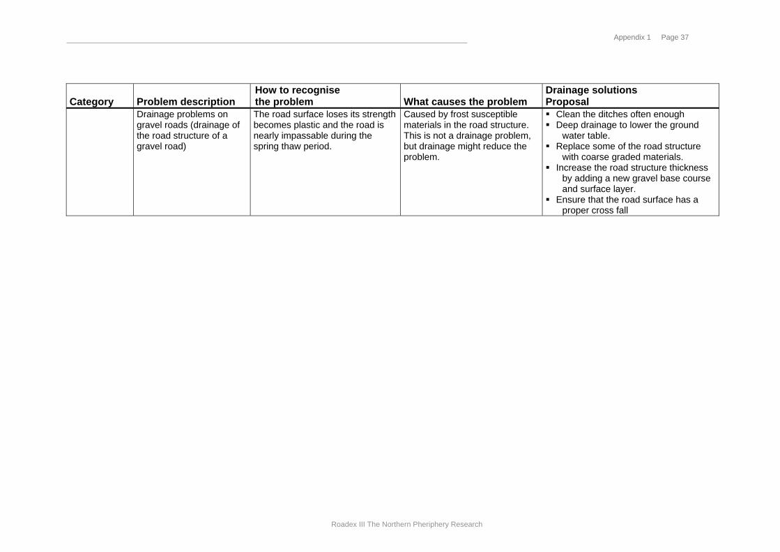
Category Problem description
How to recognise the problem What causes the problem
Drainage solutions Proposal
Drainage problems on gravel roads (drainage of the road structure of a gravel road)
The road surface loses its strength becomes plastic and the road is nearly impassable during the spring thaw period.
Caused by frost susceptible materials in the road structure. This is not a drainage problem, but drainage might reduce the problem.
! Clean the ditches often enough ! Deep drainage to lower the ground
water table. ! Replace some of the road structure
with coarse graded materials. ! Increase the road structure thickness
by adding a new gravel base course and surface layer.
! Ensure that the road surface has a proper cross fall