management of skid resistance - tiipublications.ie · related directly to the friction available to...
TRANSCRIPT

Management of Skid Resistance
AM-PAV-06045
November 2011
Asset Management &
Maintenance
Standards
AM

TRANSPORT INFRASTRUCTURE IRELAND (TII) PUBLICATIONS
About TII Transport Infrastructure Ireland (TII) is responsible for managing and improving the country’s national road and light rail networks. About TII Publications TII maintains an online suite of technical publications, which is managed through the TII Publications website. The contents of TII Publications is clearly split into ‘Standards’ and ‘Technical’ documentation. All documentation for implementation on TII schemes is collectively referred to as TII Publications (Standards), and all other documentation within the system is collectively referred to as TII Publications (Technical). This system replaces the NRA Design Manual for Roads and Bridges (NRA DMRB) and the NRA Manual of Contract Documents for Road Works (NRA MCDRW). Document Attributes Each document within TII Publications has a range of attributes associated with it, which allows for efficient access and retrieval of the document from the website. These attributes are also contained on the inside cover of each current document, for reference. For migration of documents from the NRA and RPA to the new system, each current document was assigned with new outer front and rear covers. Apart from the covers, and inside cover pages, the documents contain the same information as previously within the NRA or RPA systems, including historical references such as those contained within NRA DMRB and NRA MCDRW. Document Attributes
TII Publication Title Management of Skid Resistance TII Publication Number
AM-PAV-06045
Activity Asset Management &
Maintenance (AM)
Document Set
Standards
Stream Pavement (PAV) Publication Date November 2011
Document Number
06045 Historical Reference
NRA HD 28
NRA DMRB and MCDRW References For all documents that existed within the NRA DMRB or the NRA MCDRW prior to the launch of TII Publications, the NRA document reference used previously is listed above under ‘historical reference’. The TII Publication Number also shown above now supersedes this historical reference. All historical references within this document are deemed to be replaced by the TII Publication Number. For the equivalent TII Publication Number for all other historical references contained within this document, please refer to the TII Publications website.

Volume 7 Section 3
Part 1
NRA HD 28/11
Volume 7: Pavement Design &
Maintenance
Management of Skid Resistance
November 2011
St. Martin’s House, Waterloo Road, Dublin 4. Tel: +353 1 660 2511 Fax +353 1 668 0009 Email: [email protected] Web: www.nra.ie

Summary:
This Standard describes how the provision of appropriate levels of skid resistance for national
roads will be managed. It details how measurements of skid resistance are to be made and
interpreted and is complemented by the NRA Addendum to HD 36 (DMRB 7.5.1), which sets
out advice on surfacing material characteristics..
Published by National Roads Authority, Dublin
2011

NRA DESIGN MANUAL FOR ROADS AND BRIDGES
November2011
VOLUME 7 Pavement Design and
Maintenance:
SECTION 3 Management of Skid
Resistance
PART 1
NRA HD 28/11
Management of Skid Resistance
Contents
Chapter
1. Introduction
2. Operation
3. Measurement of Skid Resistance
4. Setting the Investigatory Level
5. Site Investigation
6. Prioritisation of Treatment
7. Use of Warning Signs
8. References
9. Enquiries
Annex 1 Background Information on the Measurement
and Interpretation of Skid Resistance
Annex 2 SCRIM Survey of Operational Procedures
Annex 3 Processing and Computation of Characteristic
SCRIM Coefficient
Annex 4 Site Investigation
Annex 5 Assessment of Collision Data
Annex 6 Use of Different Types of Test in Collision
Investigation
National Roads Authority Volume 7 Section 3
Design Manual for Roads and Bridges Part 1 NRA HD 28/11
November2011 1/1
1. INTRODUCTION
General
1.1 The purpose of this document is to describe
how the provision of appropriate levels of skid
resistance on in-service national roads, will be
managed. This document describes how
measurements of skid resistance are to be made and
interpreted and is complemented by the NRA
Addendum to HD 36 (DMRB 7.5.1), which sets out
advice on surfacing material characteristics
necessary to deliver the required skid resistance
properties.
1.2 In this document, the term “skid resistance”
refers to the frictional properties of the road surface
measured using a specified device under
standardised conditions. The term always refers to
measurements made on wet roads, unless
specifically stated otherwise. These measurements
are used to characterise the road surface and
assess the need for maintenance, but cannot be
related directly to the friction available to a road
user making a particular manoeuvre at a
particular time.
1.3 The skid resistance of a wet or damp road
surface can be substantially lower than the same
surface when dry, and is more dependent on the
condition of the surfacing material. The objective of
this Standard is to manage the risk of skidding
collisions in wet conditions so that this risk is
broadly equalised across the national road network.
This is achieved by providing a level of skid
resistance that is appropriate to the nature of the road
environment at each location on the network. The
appropriate level of skid resistance is determined
from a network collision analysis plus local
judgement of site-specific factors.
1.4 In this Standard, the provision of appropriate
levels of skid resistance is treated primarily as an
asset management issue rather than one of road
safety engineering, although the collision risk is
assessed in order to determine an appropriate level
of skid resistance for each site. Specifically, this
Standard does not address the identification of
locations or routes where road safety engineering
measures could be beneficial to reduce collisions.
1.5 This Standard provides advice and guidance
to assist the engineer in determining an appropriate
level of skid resistance for each site. It lays down the
procedure to be used for measuring the skid
resistance and, for cases where the measured skid
resistance is at or below a predetermined level, it
provides a methodology to assist the engineer in
assessing the requirement and priority for remedial
works. Remedial works will be subject to an
economic assessment of the costs and benefits
before proceeding, to promote the best use of
maintenance budgets.
Structure
1.6 Chapter 2 summarises the operation of the
skid resistance Standard. Chapters 3 to 7 describe
key components of the Standard: the measurement
of skid resistance, the process of setting
Investigatory Levels, site investigation, the
prioritisation of treatments and use of warning signs.
These chapters are supported by a number of
Annexes that give more detailed instructions or
advice.
1.7 Annex 1 provides background information
relevant to the measurement and interpretation of
skid resistance. Annex 2 gives operational details for
measuring skid resistance and Annex 3 gives the
methods for processing the raw survey data to derive
values that characterise the skid resistance.
1.8 Annex 4 and Annex 5 describe methodologies
for site investigation and for assessing collision data
respectively.
1.9 Annex 6 discusses why different test methods
are used in collision investigation.
Implementation
1.10 This Standard shall be used forthwith on all
schemes for the construction, improvement and
maintenance of national roads including motorways,
currently being prepared provided that, in the
opinion of the National Roads Authority this would
not result in significant additional expense or delay.
In such cases, managing organisations should
confirm the application of this Standard to particular
schemes with the National Roads Authority.
National Roads Authority Volume 7 Section 3
Design Manual for Roads and Bridges Part 1 NRA HD 28/11
November2011 1/2
Mandatory Sections
1.11 Sections of this document which form part of
the standards the National Roads Authority expects
in the management of skid resistance are highlighted
by being contained in boxes. There are sections
with which the managing organisation must comply
or must have agreed a suitable Departure from
Standards with the National Roads Authority.
Departures from Standards
1.12 In exceptional situations, the National Roads
Authority may be prepared to agree to a Departure
from Standards where the standard is not
realistically deliverable. Proposals to adopt
Departures from Standard must be submitted by the
managing organisation to the National Roads
Authority and formal approval received before
implementation.
Mutual Recognition
1.13 The construction and maintenance of road
pavements will normally be carried out under
contracts incorporating the National Roads
Authority Specification for Road Works
(MCDRW1). In such cases products conforming to
equivalent standards and specifications of other
member states of the European Union and tests
undertaken in other member states will be acceptable
in accordance with the terms of the 104 and 105
Series of Clauses of that Specification. Any contract
not containing these Clauses must contain suitable
clauses of mutual recognition having the same effect
regarding which advice should be sought.

National Roads Authority Volume 7 Section 3
Design Manual for Roads and Bridges Part 1 NRA HD 28/11
November2011 2/1
2. OPERATION
2.1 This Chapter summarises the procedures
for making and interpreting skid resistance
measurements on national roads.
2.2 Routine measurements of skid resistance
shall be made and processed to derive
Characteristic SCRIM Coefficient (CSC)
values in accordance with Chapter 3,
supplemented by specific instructions issued by
the Road Authority.
2.3 The CSC is an estimate of the underlying
skid resistance once the effect of seasonal
variation has been taken into account. This value
will be taken to represent the state of polish of the
road surface. These terms are explained in Annex
1.
2.4 On receipt of processed survey data, the
CSC values shall be compared with the
predetermined Investigatory Levels, to identify
lengths of road where the skid resistance is at
or below the Investigatory Level.
2.5 Investigatory Levels represent a limit,
above which the skid resistance is assumed to be
satisfactory but at or below which the road is
subject to a more detailed investigation of the skid
resistance requirements. Investigatory Levels are
assigned based on broad features of the road type
and geometry (the site category) plus specific
features of the individual site. Investigatory
Levels will be reviewed on a rolling programme,
to ensure that changes in the network are
identified, local experience is applied and
consistency is achieved. The process for setting
Investigatory Levels and the Investigatory Levels
for each site category is described in Chapter 4.
2.6 Wherever the CSC is at or below the
assigned Investigatory Level a site investigation
shall be carried out, to determine whether
treatment to improve the skid resistance is
required or whether some other action is
required.
2.7 A site investigation shall also be carried
out if, in the normal course of collision
investigation processes separate from this
Standard, sites are identified where increased
wet or skidding collision levels have been
observed.
2.8 The process of site investigation is
described in Chapter 5. The decision of whether
treatment is necessary is unlikely to be clear-cut,
but requires professional engineering judgement
taking into account local experience, the nature of
the site, the condition of the road surfacing and
the recent collision history. If successive site
investigations show that treatment is not
warranted at the current level of skid resistance
then consideration should be given to lowering the
Investigatory Level.
2.9 The processes of setting Investigatory
Levels and undertaking site investigations are
complementary, since local knowledge and
experience gained through conducting detailed
site investigations can be used to refine the
criteria for setting Investigatory Levels for similar
types of site.
2.10 The process of site investigation will result
in a number of lengths being recommended as
needing treatment to improve the skid resistance.
The priority for treatment will be established
taking into account the observed collision history,
the need for other maintenance works in the
vicinity, the cost and the budget available for the
works. This process is described in Chapter 6.
2.11 Signs warning road users that the road
could be slippery shall be erected, as described
in Chapter 7.
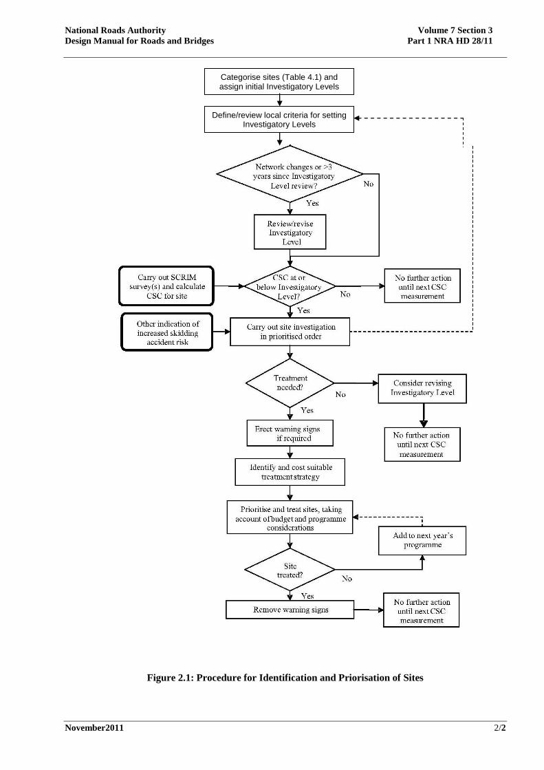
2.12 The decision-making process leading to the
identification and prioritisation of sites for
treatment is summarised in Figure 2.1.
National Roads Authority Volume 7 Section 3
Design Manual for Roads and Bridges Part 1 NRA HD 28/11
November2011 2/2
Figure 2.1: Procedure for Identification and Priorisation of Sites
Categorise sites (Table 4.1) and assign initial Investigatory Levels
Define/review local criteria for setting Investigatory Levels
National Roads Authority Volume 7 Section 3
Design Manual for Roads and Bridges Part 1 NRA HD 28/11
November2011 3/1
3. MEASUREMENT OF SKID RESISTANCE
Measurement equipment
3.1 Various types of equipment are available
for measuring skid resistance. In different ways,
all measure the force developed on a rubber tyre
or slider passing over a wetted road surface and
derive a value that is related to the coefficient of
friction and the state of polish of the road surface.
3.2 However, the results from the different
devices are not directly interchangeable. For this
reason only one device is to be used for
monitoring the in-service skid resistance of
national roads for the purposes of this Standard.
3.3 Measurements for monitoring the in-
service skid resistance of national roads, in line
with this Standard, shall be made with a
Sideway-force Coefficient Routine
Investigation Machine (SCRIM).
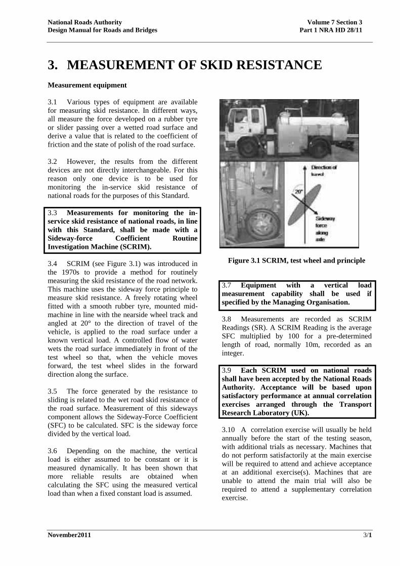
3.4 SCRIM (see Figure 3.1) was introduced in
the 1970s to provide a method for routinely
measuring the skid resistance of the road network.
This machine uses the sideway force principle to
measure skid resistance. A freely rotating wheel
fitted with a smooth rubber tyre, mounted mid-
machine in line with the nearside wheel track and
angled at 20° to the direction of travel of the
vehicle, is applied to the road surface under a
known vertical load. A controlled flow of water
wets the road surface immediately in front of the
test wheel so that, when the vehicle moves
forward, the test wheel slides in the forward
direction along the surface.
3.5 The force generated by the resistance to
sliding is related to the wet road skid resistance of
the road surface. Measurement of this sideways
component allows the Sideway-Force Coefficient
(SFC) to be calculated. SFC is the sideway force
divided by the vertical load.
3.6 Depending on the machine, the vertical
load is either assumed to be constant or it is
measured dynamically. It has been shown that
more reliable results are obtained when
calculating the SFC using the measured vertical
load than when a fixed constant load is assumed.
Figure 3.1 SCRIM, test wheel and principle
3.7 Equipment with a vertical load
measurement capability shall be used if
specified by the Managing Organisation.
3.8 Measurements are recorded as SCRIM
Readings (SR). A SCRIM Reading is the average
SFC multiplied by 100 for a pre-determined
length of road, normally 10m, recorded as an
integer.
3.9 Each SCRIM used on national roads
shall have been accepted by the National Roads
Authority. Acceptance will be based upon
satisfactory performance at annual correlation
exercises arranged through the Transport
Research Laboratory (UK).
3.10 A correlation exercise will usually be held
annually before the start of the testing season,
with additional trials as necessary. Machines that
do not perform satisfactorily at the main exercise
will be required to attend and achieve acceptance
at an additional exercise(s). Machines that are
unable to attend the main trial will also be
required to attend a supplementary correlation
exercise.

National Roads Authority Volume 7 Section 3
Design Manual for Roads and Bridges Part 1 NRA HD 28/11
November2011 3/2
Use of SCRIM
3.11 Skid resistance is not a constant, but is
influenced by various factors, including
temperature, test speed and weather conditions,
plus longer-term effects such as seasonal variation
and changes in traffic flow. Further information is
given in Annex 2. For the purpose of this
Standard, SCRIM measurements will be made
under standardised conditions to control these
effects as far as possible, including:
• limiting the testing season to a specific time
of year;
• specifying a standard test speed;
• specifying the test line to be followed;
• specifying the ambient conditions under
which acceptable measurements may be
made.
Further details are given in Annex 2.
3.12 SCRIM operators providing
measurements under this Standard must
develop appropriate procedures to ensure that
measurements are carried out safely and to a
standard of quality agreed with the Managing
Organisation. This must include adhering to
the procedures given in British Standard
BS7941-1 (1999) for making skid resistance
measurements with a SCRIM and for
calibrating and making regular checks on the
equipment, and the further instructions given
in this Chapter and in Annex 2.
Survey Strategy
3.13 The surveying strategy is planned so that
the effects of seasonal variation, both within a
single season and/or between successive years,
can be taken into account in the determination of
the CSC for any particular length of road.
3.14 Because of the different nature of traffic
patterns and road networks , the way in which
surveys are planned and seasonal variation is
accounted for may be different for different
circumstances. Alternative monitoring strategies
to be followed are explained as part of Annex 3.
3.15 The whole national road network will
normally be tested once during each testing
season. However, the rate at which skid resistance
changes may be slow on some roads, particularly
where traffic volumes are low. In such
circumstances it may not be necessary to monitor
annually.
3.16 The Managing Organisation will specify
the network to be surveyed, the test lane, the
survey strategy and the method and/or the
accuracy of location referencing required.
Processing of survey data
3.17 After collection, survey data will be
validated and subject to processing to determine
the CSC values that will be used for further
analysis. Validation and processing will be carried
out as specified by the Managing Organisation.
3.18 Typically, processing will include:
• application of correction factors, e.g. in
circumstances where it was not possible to
maintain the specified standard test speed;
• multiplication by the Index of SFC
applicable to the SCRIM at the time it was
making the measurement;
• calculation of the CSC;
• aggregation of raw data to longer averaging
lengths, typically 100m or 50m, for further
analysis (see paragraph 4.8).
3.19 Further details of the processing are set out
in Annex 3.
3.20 On receipt of processed survey data, the
Managing Organisation shall check that the
whole of the specified network has been
surveyed. Appropriate action must be taken to
ensure that, as far as possible, valid data is
obtained in the following planned survey for
locations where there is missing or invalid data
in the current survey.

National Roads Authority Volume 7 Section 3
Design Manual for Roads and Bridges Part 1 NRA HD 28/11
November2011 4/1
4. SETTING THE INVESTIGATORY LEVEL Objective
4.1 The objective of setting the Investigatory
Level is to assess the nature of the site and assign
an appropriate level of skid resistance, at or below
which a more detailed site investigation must be
undertaken. It is important that the Investigatory
Level is not set too low. If, during the site
investigation, the Investigatory Level is found to
be too high then it can be lowered. However, if
the Investigatory Level is initially set at too low a
level then the need to improve the skid resistance
may not be detected until it has already fallen
further than is desirable.
4.2 The Managing Organisation shall assign
a Site Category and Investigatory Level to each
part of the network, so that the Investigatory
Level can be compared with the CSC. This
information must be recorded in a format
agreed with the National Roads Authority,
together with the date of assessment.
Procedure
4.3 Site categories and associated Investigatory
Levels are defined in Table 4.1. These categories
have been developed for national roads and may
not be applicable to regional and local roads,
which are more diverse in nature.
4.4 The site category most appropriate to the
layout of the site will be selected from the list in
Table 4.1. If more than one site category is
appropriate then the site category with the higher
Investigatory Level will be selected or where the
highest Investigatory Levels are the same then the
category highest up the Table will be selected.
4.5 Slip roads will be allocated to categories
[B, Q, G or S] as appropriate to their length and
layout.
4.6 A single site category can vary in length
from a few tens of metres to several kilometres,
depending on the nature of the site. The length of
site categories [Q and K] will normally be the
50m approach to the feature, but this shall be
extended where justified by site characteristics,
e.g. if queuing traffic creates an additional risk, to
allow for traffic joining the back of the queue.
4.7 Investigatory Levels are applied to the
mean CSC within 100m averaging lengths, except
that the Investigatory Levels for site category R
are based on 10m averaging lengths. Shorter
lengths will be necessary where the site category
is less than 100m long or at the end of a site
category longer than 100m. Residual lengths less
than 50% of a complete averaging length may be
appended to the penultimate length, providing the
site category is the same.

National Roads Authority Volume 7 Section 3
Design Manual for Roads and Bridges Part1 NRA HD28/11
November2011 4/2
Site category and definition Investigatory Level at 50km/h
0.30 0.35 0.40 0.45 0.50 0.55 0.60 0.65
A Motorway
B Dual carriageway non-event
C Single carriageway non-event
G1 Gradient 5-10% longer than 50m
G2 Gradient >10% longer than 50m
K Approaches to traffic signals. pedestrian crossings
Q Approaches to and across major and minor junctions,
R Roundabout
S1 Bend radius <250m – dual carriageway
S2 Bend radius <250m – single carriageway
Traffic > 250 commercial vehicles / lane/ per day
Traffic < 250 commercial vehicles/lane/ per day
Notes:
1 Investigatory Levels are for the mean skidding resistance within the appropriate averaging length
2 Investigatory Levels for site categories A, B, C, G and S are based on 100m averaging lengths or the
length of the feature if it is shorter.
3 Investigatory Levels and averaging lengths for site categories K and Q are based on the 50m approach
to the feature but this shall be extended when justified by local site characteristics.
4 Investigatory Levels for site category R are based on 10m lengths.
5 Residual lengths less than 50% of a complete averaging length may be attached to the penultimate full
averaging length, providing the site category is the same.
6 As part of site investigation, individual values within each averaging length should be examined and
the significance of any values which are substantially lower than the mean value assessed.
Table 4.1 Site categories and Investigatory Levels

National Roads Authority Volume 7 Section 3
Design Manual for Roads and Bridges Part 1 NRA HD28/11
November2011 4/3
4.8 Roads within the site category with no
exceptional risk of skidding collisions will be
assigned the standard Investigatory Level. It is
envisaged that this will apply to the majority of
sites. The following factors could influence the
choice of a higher Investigatory Level. However,
a higher Investigatory Level will not be
appropriate if the overall level of risk is low (e.g.
because of low traffic flow or low traffic speed) or
if the risk has been mitigated by other means (e.g.
through clear signing of a hazard or reduced speed
limit.)
• Notable potential for conflict between road
users at the site, particularly where the
outcome is likely to have severe
consequences, e.g. a head-on or side impact
at speed.
• Road geometry departing substantially from
current Standards.
• Known incidence of queuing where the
traffic speed is otherwise high.
• Accesses onto the main carriageway, if they
are busy (e.g. for a service station) or have
poor advance visibility, or if the speed of
leaving or joining traffic creates conflict
with other traffic on the main carriageway.
• Two or more events in proximity, e.g. a
junction on a downhill gradient.
• Low texture depth (less than 0.8mm
measured as Mean Profile Depths (MPD))),
except for High Friction Surfacing
materials.
• Bends where the traffic speed and/or
geometry is judged to give rise to added
risk. This could apply to some sites in non-
event categories as well as sites in the bend
categories.
• Sharp left-hand bends, such as on the
approach to or exit from a roundabout,
where greater polishing action by traffic
could lead to lower skid resistance
occurring in the right-hand wheel path than
is measured in the left-hand wheel path.
• For non-event categories B and C: approach
to slip road leaving main carriageway or
merging area downstream of slip road
joining main carriageway, except if low
traffic flow means that the slip road gives
rise to little added conflict between road
users, compared with the mainline.
• For approaches to minor junctions: poor
advance visibility; high risk of head-on
collisions; high approach speed, except if
this is mitigated (e.g. by adequate taper
length for traffic leaving and joining the
main carriageway and/or a separate lane for
right turning traffic).
• For pedestrian crossings: poor advance
visibility; high approach speed.
• For roundabouts: high speed of circulating
traffic; high incidence of cyclists or
motorcyclists; absence of signalised control
on roundabouts at grade separated
interchanges.
• For all site categories on all-purpose roads,
significant numbers of pedestrians crossing
at a given location.
• Known history of collision occurrence
being more frequent than normal,
particularly in wet conditions or where
skidding is reported.
•
4.9 A review of the Investigatory Level shall
be carried out when a significant change to the
network is made.
4.10 Notwithstanding the above, a procedure
shall be put in place to ensure that the
Investigatory Levels are reviewed at least every
three years unless agreed otherwise with the
National Roads Authority.

National Roads Authority Volume 7 Section 3
Design Manual for Roads and Bridges Part 1 NRA HD28/11
November2011 5/1
5. SITE INVESTIGATION
Objectives and outcomes
5.1 Sites where the CSC is at or below the
Investigatory Level require a detailed
investigation. The objective is to determine
whether a surface treatment is justified to reduce
the risk of collisions, specifically collisions in wet
conditions or involving skidding, whether some
other form of action is required, or whether the
site should be kept under review. This
investigation is an important part of the operation
of the skid resistance Standard. In conjunction
with the process of setting Investigatory Levels,
the objective is to promote effective targeting of
treatments.
5.2 Treatment will normally be a surface
treatment to improve the skid resistance.
However, if the site investigation identifies any
characteristic of the site or road user behaviour
that suggests other road safety engineering
measures could be appropriate, then the
appropriate specialist dealing with safety schemes
must be consulted before deciding upon the best
course of action. If it is found that there is a need
for other types of routine maintenance, for
example re-application of road markings or
additional road sweeping, then this must also be
addressed.
5.3 Some form of treatment will be justified if:
• based on a collision analysis, the collision
rate observed is higher than the expected
average collision rate for the type of site
being considered;
• based on a collision analysis, the wet road
collision rate is higher than the expected
average wet road collision rate or involving
skidding for the type of site being
considered;
• the nature of the individual site and the
demands of road users mean that a higher
collision risk (compared with other sites in
the same category) might be expected with
the skid resistance at its current value or if
it were to fall further before the next
measurement. In this case, preventive
treatment is justified to pre-empt a potential
increase in collision risk.
5.4 If none of the above are true then there is
currently no justification for treatment to increase
the skid resistance. If the site remains below the
Investigatory Level at the next measurement, then
it will automatically be subject to a further
investigation. That is, sites with skid resistance
remaining below the Investigatory Level are
automatically kept under review.
5.5 Further details of making these assessments
are given in Annex 4 on site investigation and
Annex 5 on assessment of collision data.
5.6 If the skid resistance and collision pattern
remain stable for an extended period, for example,
more than 3 years, then lowering the Investigatory
Level should be considered. However, it is
important that stability is observed before
reducing the Investigatory Level, because, unless
the skid resistance falls further, regular
investigation that would detect an increase in
collisions would no longer be prompted by the
skid resistance Standard.
Procedure
5.7 Sites requiring investigation shall be
identified as soon as practicable on receipt of
the CSC values.
5.8 CSC values should be used in preference to
single run survey values that have not been
adjusted for seasonal effects, as the latter are less
reliable. However, if single run survey data
indicate that the skid resistance is significantly
below the Investigatory Level (e.g. at least 0.05
units SCRIM coefficient below) then it is likely
that the CSC will also be found to be below the
Investigatory Level. Single run data can therefore
be used to give early warning of sites requiring
investigation, but any decision on the need for
treatment should normally be based on the CSC.
5.9 Site investigations shall be carried out in
a prioritised order, by personnel experienced
in pavement engineering.
5.10 Site investigations will be prioritised
initially on the basis of the amount by which the
skid resistance is below the Investigatory Level.
National Roads Authority Volume 7 Section 3
Design Manual for Roads and Bridges Part 1 NRA HD28/11
November2011 5/2
This order may be refined to take into account the
efficiency of conducting investigations and as a
result of other information gathered during the
early part of the investigation, such as the recent
collision history.
5.11 Persons with relevant local experience must
be identified, and should be consulted if
appropriate, during the site investigation process.
These will include the person locally responsible
for collision investigation and prevention.
5.12 The results of the investigation, including
whether further action is required, shall be
documented and retained together with the
identity of the assessor and other parties
consulted.

National Roads Authority Volume 7 Section 3
Design Manual for Roads and Bridges Part 1 NRA HD28/11
November2011 6/1
6. PRIORITISATION OF TREATMENT
6.1 Site investigation results in the
identification of lengths of pavement where
treatment is recommended to improve the skid
resistance. This chapter addresses the
prioritisation of these treatments on the
assumption that budget resources are limited. If
other actions are identified as a result of the site
investigation then these must be prioritised as
appropriate.
6.2 The NRA Addenda to HD 36, HD 37 and
HD 38 (DMRB 7.5.1-3) give advice about the
choice of surfacing materials to provide the
appropriate level of skid resistance and about the
use of re-texturing treatments to provide short-
term improvements to skid resistance and/or
texture depth. Other aspects of pavement
condition must also be taken into account in
selecting the most appropriate form of treatment.
6.3 The most appropriate form of treatment
shall be identified for each treatment length
taking account of current advice.
6.4 Priority must be given to completing
treatments where the skid resistance is
substantially below the Investigatory Level (e.g.
at least 0.05 units CSC below), or low skid
resistance is combined with a low texture depth,
or the collision history shows there to be a clearly
increased risk of wet or skidding collisions. In
other cases, treatment will be programmed as a
longer-term measure taking into consideration
other maintenance requirements.
6.5 A comparison of the estimated collision
saving and the cost-effectiveness of treatments
can be used to assist in establishing the relative
priority of treatments at different locations. The
National Roads Authority will provide
information that can be used to make this
assessment. Other estimates of collision savings
may be used if backed up by local experience or
other information.
6.6 The cost effectiveness of treatments at
different locations can be calculated by dividing
the estimated collision saving by the anticipated
cost of treatment.
6.7 The priority for treatment should be
established for all new treatment lengths and for
those lengths previously recommended for
treatment to improve the skid resistance, but
where treatment has not yet been carried out or
definitely programmed. If more than a year has
elapsed since the site investigation was carried out
then the collision history and priority for
treatment must be re-examined using the most
recent data available. This programme should be
reviewed and progress recorded at appropriate
intervals.

National Roads Authority Volume 7 Section 3
Design Manual for Roads and Bridges Part 1 NRA HD28/11
November2011 6/2
7. USE OF WARNING SIGNS
7.1 Warning signs shall be erected at sites
where the need for treatment to improve skid
resistance has been identified following a site
investigation. Sites identified in this way shall
be referred on an individual basis to the
National Roads Authority for a decision on the
provision of warning signs.
7.2 This strategy provides a targeted use of
signs and is designed to avoid a proliferation of
signs that would undermine their effectiveness
and would not make best use of resources.
7.3 Since warning signs are erected (if
required) after a site investigation, it is
particularly important to complete site
investigations in a prioritised order and within a
reasonable time period, so that warning signs can
be placed where they are needed without undue
delay.
7.4 The slippery roads warning sign (Sign
W134) is to be used in accordance with the
Traffic Signs Manual.
7.5 A visual inspection of the site shall be
made after the signs are erected to confirm
that they have been erected and correctly
placed and a record of this observation shall be
made and retained.
7.6 Depending on the nature of the surface
treatment, it may be necessary to leave slippery
road warning signs in place for a period after a
new surface is opened to traffic. Additionally, at
sites where the risk of skidding may temporarily
increase after surface treatment, it may be
necessary to erect warning slippery road signs if
not already in place.
7.7 Warning signs shall be removed as soon
as they are no longer required.
National Roads Authority Volume 7 Section 3
Design Manual for Roads and Bridges Part 1 NRA HD28/11
November2011 8/1
8. REFERENCES LR738; Hosking JR and Woodford GC,
“Measurement of Skidding Resistance Part ii:
Factors Affecting the Slipperiness of a Road
Surface”; TRRL.
BS7941; Part1; “Methods for Measuring the Skid
Resistance of Pavement Surfaces. Side-ways Force
Coefficient Routine Investigation Machine”, BSI.
NRA Design Manual for Roads and Bridges
(NRA DMRB)
HD 36 (DMRB 7.5.1) Surfacing Materials for
New and Maintenance Construction.
NRA Addendum to HD 37 (DMRB 7.5.2)
Bituminous Surfacing Materials and
Techniques.
NRA Addendum to HD 38 (DMRB 7.5.3)
Concrete Surfacing and Materials.
Traffic Signs Manual, Department of Transport

National Roads Authority Volume 7 Section 3
Design Manual for Roads and Bridges Part 1 NRA HD28/11
November2011 9/1
9. ENQUIRIES
All technical enquiries or comments on this Standard should be sent in writing as appropriate to:
National Roads Authority
St Martin’s House
Waterloo Road
Dublin 4
...................................................
TIM AHERN
Head of Engineering

National Roads Authority Volume 7 Section 3
Design Manual for Roads and Bridges Part 1 NRA HD28/11
November2011 A1/1
ANNEX 1: BACKGROUND INFORMATION ON THE
MEASUREMENT AND INTERPRETATION OF
SKID RESISTANCE General
A1.1 When a vehicle travels over a road, each
part of the tyre in contact with the road surface is
momentarily at rest. The frictional forces
generated at these stationary contact areas
between the tyre and the road surface can allow
vehicles to be manoeuvred. However, a vehicle
will start to skid whenever the available friction
between the road surface and the tyre is
insufficient to meet the demands of the driver in
whatever manoeuvre (including braking) they are
attempting to make.
A1.2 The friction available to a driver attempting
a particular manoeuvre depends on many different
factors. The influence of road surface
characteristics is described below. Other factors
include the vehicle’s tyres and braking system, the
dynamic interaction of the vehicle suspension
with the road geometry and environmental factors,
such as the temperature and the presence of water
or other contaminants. The objective of
measurements carried out under the operation of
this Standard is to characterise the influence of the
road surface skid resistance and hence define the
skid resistance available to road users.
Road Surface Properties
A1.3 The contribution of the road surface to the
overall friction is known as skid resistance. In
practice, it is found that the skid resistance
measured on dry, in-service road surfaces is
generally high, but that lower and more variable
measurements are obtained when the same road
surfaces are wet or damp. For this reason,
measurements of skid resistance for the purpose
of routine condition monitoring are made on
wetted road surfaces.
A1.4 The level of (wet road) skid resistance is
dependent on two key properties of the surface,
the microtexture and the texture depth. The fine
scale microtexture, on the surface of aggregate
particles and provided by the fines in the mixture,
is the main contributor to skid resistance at low
speeds and the main property measured in wet
skid resistance tests. Greater texture depth
generates friction by physically deforming the
tyre surface and also provides rapid drainage
routes between the tyre and road surface.
A1.5 The effects of microtexture and texture
depth combine to influence the skid resistance at
higher speeds. The standard SCRIM measurement
is carried out at a slip speed less than 20km/h,
much lower than the slip speed in locked-wheel
braking from normal traffic speed. The typical
reduction of skid resistance from the 20km/h
value at higher speeds, and the influence of
texture depth, is illustrated in Table A1.1. The
effect of texture depth becomes apparent at speeds
as low as 50 km/h, but is increasingly significant
at higher speeds.
Speed Texture depth (mm MPD)
Below 0.5 0.5 – 0.8 Above 0.8
50 km/h 40% 30% 25%
120 km/h 70% 60% 50%
Table A1.1 Typical Reduction in Skid
Resistance Compared with 20km/h Value
Effect of Traffic
A1.6 Under the action of traffic, the microtexture
becomes “polished”, leading to a reduction in skid
resistance. The NRA Addendum to HD 36
(DMRB 7.5.1) requires the components of the
surfacing mixture to satisfy certain criteria in
relation to their resistance to polishing, so that
surfacing materials generally provide adequate
skid resistance during their service lifetimes.
A1.7 In combination with the specification of
surfacing materials, the skid resistance of roads is
monitored to identify areas where the
microtexture has been lost as the surface has been
polished by traffic and treatment might, therefore,
be needed to improve the skid resistance. This is
necessary because the performance in service
cannot be predicted precisely from the properties
of the surfacing components and traffic levels,
and the effects of manoeuvring vehicles at the

National Roads Authority Volume 7 Section 3
Design Manual for Roads and Bridges Part 1 NRA HD28/11
November2011 A1/2
location might be greater than was anticipated at
the time the surfacing was designed.
A1.8 Similarly, the texture depth of road
surfacings can reduce with time under the
combined influences of traffic flow, temperature
and the nature of the surface and is also
monitored.
Early Life Skid Resistance of Asphalt
Surfacings
A1.9 Asphalt surfacings exhibit different skid
resistance falls. This phenomenon is not within
the scope of this document, which is concerned
with in-service condition rather than the
properties in the initial period.
A1.10 Sections of road that exhibit these
different skid resistance properties during this the
initial period, must be identified, so that they can
be excluded from certain types of analyses, as
described in Chapter 3 and Annex 4 of this
Standard. The duration of this initial phase will
depend on local conditions but, for the purpose of
interpreting skid resistance measurements, it is
assumed that the surface has reached an
equilibrium state one year after opening to traffic
on national roads.
Seasonal Variation of Skid Resistance
A1.11 After the initial period of wearing in, road
surfaces reach an equilibrium state of polishing.
For roads where the traffic level is constant, the
skid resistance will then fluctuate through
seasonal weathering and polishing cycles but will
remain at about a constant level for many years. If
the traffic level subsequently increases or
decreases, the position of the equilibrium will
shift so that a lower or higher overall level of skid
resistance is observed, but with the same seasonal
fluctuation superimposed.
A1.12 An example of long-term variation in skid
resistance is shown in Figure A1.1. A suggested
explanation for the annual variation is that in the
winter (October to March) when the roads are wet
for much of the time, the detritus is mainly gritty
so that the road surface becomes harsh and the
skid resistance rises. The lowest skid resistance is
generally observed in the summer period, when
the roads are wet for a relatively short time, the
detritus on them is mainly dusty so that the road
surface becomes polished and the skid resistance
falls. In practice, the minimum skid resistance
varies from year to year and occurs during
different periods depending on the prevailing
weather conditions.
Figure A1.1 Example of Long-Term Variation
in Skid Resistance (from LR 738)
A1.13 Because the skid resistance varies
continuously, various strategies have been
developed to provide a measurement that
characterises the state of polish of the
microtexture. Survey strategy and processing
procedures are designed to reduce the effect of the
variation within a year and/or between successive
years, so the sites with low skid resistance can be
identified more accurately. Typically,
measurements are made during the summer
period, when the lowest measured values are
observed.
A1.14 The survey and analysis methods to be
used for the purposes of this Standard are
described in Chapter 3, Annex 2 and Annex 3 of
this Standard.
Standardised Measurements
A1.15 To characterise the condition of the
microtexture, measurements of skid resistance are
made under standardised conditions that restrict
the influence of other factors on the measurement
as far as possible. For example, measurements are
made at a specified speed, using a specified tyre
and a controlled amount of water. Corrections
may be applied to the measured value where the
specified standard conditions were not achieved,
e.g. where it was not safe to maintain the specified
speed. Further details of test procedures are given
in Chapter 3.
A1.16 The measurements made and
interpreted according to this Standard provide
a guide to the general condition of the road to
assist in maintenance planning. Because they
indicate the general level of skid resistance
under standardised conditions, the values do

National Roads Authority Volume 7 Section 3
Design Manual for Roads and Bridges Part 1 NRA HD28/11
November2011 A1/3
not relate directly to specific collision
situations, where other factors such as the tyre
condition, vehicle speed and manoeuvre
attempted all influence the level of friction
generated at that time.
A1.17 In contrast, skid tests carried out by the
Gardai for the purpose of reconstructing the
situation leading to an collision are intended to
recreate the specific conditions of the collision.
The results of these different types of test cannot
be compared precisely. See Annex 6.
Relationship to Collision Risk
A1.18 Within normal ranges, low skid resistance
does not cause collisions on its own although,
depending on the particular circumstances, it may
be a significant contributory factor. The level of
skid resistance, even on a polished surface, will
generally be adequate to achieve normal
acceleration, deceleration and cornering
manoeuvres on sound surfaces that are wet but
free from other contamination. However, higher
skid resistance can allow manoeuvres that demand
higher friction to be completed, e.g. to stop
quickly or corner sharply. Higher skid resistance
can therefore reduce collisions in cases where
drivers need to complete a more demanding
manoeuvre in order to avoid an collision. A key
part of this Standard is the judgement of locations
where this is more likely to occur, so that the
provision of higher levels of skid resistance can
be targeted at these locations.
A1.19 Collision analyses have shown that there
are relationships between measured skid
resistance and collision risk. These relationships
are not precise, in that differences in skid
resistance may account for only a relatively small
part of the difference in collision risk between
individual sites because of all the other factors
involved. Nevertheless, they have allowed general
observations to be drawn that make it possible to
provide guidance for managing the provision of
skid resistance on the network.
A1.20 The influence of skid resistance on
collision risk is markedly different for roads with
different characteristics. For this reason, site
categories have been defined to group roads with
similar characteristics.
A1.21 For some site categories, no statistically
significant relationship, or only a weak
relationship, is observed between skid resistance
and collision risk. A good example of this is
motorways, where the road design has effectively
reduced the potential for conflict between road
users. Although the skid resistance is still
important, because of the need to provide uniform
road characteristics, the level of skid resistance
can be lower than other categories.
A1.22 For other site categories, progressively
more collisions are observed, on average, as the
skid resistance falls. For these categories, there
are benefits in maintaining a higher level of skid
resistance to contribute to reducing the number of
collisions at these sites.
A1.23 However, not all sites within a single
category are equivalent in terms of their collision
risk. Figure A1.2 illustrates the range in collision
risk present for individual sites within a single site
category. This range is not surprising when the
range of characteristics present within a single
nominal site category is considered, e.g. in road
design and traffic flow. It should also be noted
that there is no boundary at which the skid
resistance passes from being “safe” to being
“dangerous”.
A1.24 Judgement of the relative collision risk
and appropriate level of skid resistance for
different sites within the same category forms a
key part of the effective operation of this
Standard.
Figure A1.2 Collision Risk and Skid
Resistance - Variation Within Site Category
(UK HD 28)

National Roads Authority Volume 7 Section 3
Design Manual for Roads and Bridges Part 1 NRA HD28/11
November2011 A2/1
ANNEX 2: SCRIM SURVEY OF OPERATIONAL
PROCEDURES A2.1 This Annex lists the standard testing
procedures that are required to limit the variability
of skid resistance measurements resulting from
factors other than the road surface condition, e.g.,
the test speed.
Testing Season
A2.2 For standardised tests, measurements
shall be made during the testing season,
defined as the summer period 1 May – 30
September.
A2.3 In exceptional circumstances the testing
season may be extended but only with the prior
agreement of the National Roads Authority.
Testing Speed
A2.4 On Motorways and Dual Carriageway
All Purpose Roads where the posted speed
limit is greater than 80km/hr, the target test
vehicle speed is 80km/h. On all other roads, or
where a SCRIM is being used without dynamic
vertical load measurement, the target test
vehicle speed is 50km/h.
A2.5 The SCRIM driver shall maintain a
vehicle speed as close to the target test speed as
possible. This is achievable for most parts of
the network.
A2.6 If it is not safe or practical to maintain the
target speed then, in exceptional circumstances, a
different speed may be used at the discretion of
the SCRIM driver. The safety of the SCRIM and
other road users has priority at all times.
A2.7 The Investigatory Levels for the CSC
values defined in Chapter 4 have been set in terms
of the 50km/h standard testing speed. The method
for applying speed corrections is given in Annex 3
of this Standard.
Testing Lane and Line
A2.8 For most roads, the leftmost lane will be
tested in both directions of travel. This lane
usually carries the most heavy traffic and can,
therefore, be expected to show the lowest skid
resistance. In areas where this is not the case (for
example, approaching points where routes diverge
and a greater proportion of heavy vehicles uses
the offside lane) then a different lane, or more
than one lane will be tested.
A2.9 The test lane shall be as specified by the
Managing Organisation.
A2.10 Measurements shall be carried out with
the test wheel in the nearside (left) wheel path
of the running lane unless an alternative test
line has been agreed with the Managing
Organisation.
A2.11 If it is necessary for the SCRIM to
deviate from the test line (e.g. to avoid a
physical obstruction or surface contamination)
the data shall be marked as invalid and
eliminated from the standard analysis
procedure.
A2.12 On urban roads where roadside parking in
unmarked positions is commonplace, there may
be two pairs of wheel paths – one followed at
times of day when parked cars are mostly absent
and another when they are largely present. In such
circumstances the line that normally carries the
most commercial vehicle traffic must be followed.
A2.13 In situations where the test line is prone to
physical obstruction, for example by parked cars,
then an alternative test line must be agreed with
the Managing Organisation to avoid recording
invalid data for the same length of road in
successive years. Testing the offside wheel path
might be an appropriate alternative in these
circumstances, with the aim of achieving a
consistent test path, year on year.
Testing on Bends
A2.14 There are no special requirements for
testing on bends. At locations where a sharp bend
is combined with traffic braking or accelerating,
the wheel path on the outside of the bend can
become more polished than the inside wheel path.
This is taken into account in setting the
Investigatory Level (See Chapter 4) and during
the site investigation (See Paragraph A4.15).

National Roads Authority Volume 7 Section 3
Design Manual for Roads and Bridges Part 1 NRA HD28/11
November2011 A2/2
Testing on Roundabouts
A2.15 Roundabouts can present practical
problems regarding potential traffic conflicts and
testing speed. They range from small, mini-
roundabouts to large grade-separated
interchanges. Larger roundabouts may have free-
flowing traffic or traffic light controls at certain
times of day.
A2.16 Mini-roundabouts or small island
roundabouts should be treated as part of the main
carriageway test line and do not need to be tested
separately. (This applies to the testing procedure –
the roundabout section may be assigned to a
different Site Category to that of the main line.)
A2.17 On most roundabouts or interchanges, a
line equivalent to the outermost lane should be
tested.
A2.18 On roundabouts with lane markings for
specific routes, a representative line should be
chosen broadly following the most polished path.
Usually this will be that followed by most heavy
vehicles, which, because of their size, may not be
able to keep to the marked lanes.
A2.19 The test line(s) to be followed at
roundabouts shall be as agreed by the SCRIM
operator and the Managing Organisation.
They will take into account the need for
consistency in representative measurements in
successive surveys and possible variations in
Site Category through the intersection.
A2.20 On some smaller roundabouts where the
distance between the arms is short, it may be
appropriate to record data at a shorter interval
than the standard 10m length. Changes to the
recording interval will be specified by the
Managing Organisation.
Ambient Conditions During Testing
A2.21 The ambient conditions can have an effect
both on the skid resistance of the road and on the
measurements. The SCRIM operator shall record
the weather conditions at the time of the survey as
required by BS7941-1 (1999).
A2.22 Testing in extremely strong side winds
must be avoided because these can affect the
measurements by creating turbulence under the
vehicle that causes the water jet to be diverted
from the correct line.
A2.23 Testing must be avoided in heavy rainfall
or where there is standing water on the road
surface. Excess water on the surface can affect the
drag forces at the tyre/road interface and influence
the measurements.
A2.24 Measurements shall not be undertaken
where the air temperature is below 5°C.
A2.25 The maintaining organisation shall
maintain a record of general conditions
throughout the testing season. Both the SCRIM
operator and the maintaining organisation shall
endeavour to record any road conditions that
could affect the results.
A2.26 Contamination of the road surface by
mud, oil, grit, or other contaminants is to be noted
and the affected measurements identified (in the
same way as for out-of-line testing) so that results
are eliminated from the standard analysis
procedure. If the contamination is severe,
emergency action may be required to remove the
contamination. In this case the problem must be
reported without delay to the Managing
Organisation, together with the relevant results if
possiblefor appropriate action to be carried out.
National Roads Authority Volume 7 Section 3
Design Manual for Roads and Bridges Part 1 NRA HD28/11
November2011 A3/1
ANNEX 3: PROCESSING AND COMPUTATION OF
CHARACTERISTIC SCRIM COEFFICIENT A3.1 This Chapter lists the processing options
that may be required by the Managing
Organisation. Options that are required must be
applied in the order listed below.
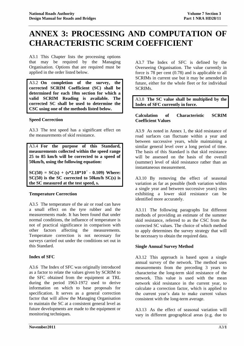
A3.2 On completion of the survey, the
corrected SCRIM Coefficient (SC) shall be
determined for each 10m section for which a
valid SCRIM Reading is available. The
corrected SC shall be used to determine the
CSC using one of the methods listed below.
Speed Correction
A3.3 The test speed has a significant effect on
the measurements of skid resistance.
A3.4 For the purpose of this Standard,
measurements collected within the speed range
25 to 85 km/h will be corrected to a speed of
50km/h, using the following equation:
SC(50) = SC(s) + (s*2.18*10
-3
- 0.109) Where:
SC(50) is the SC corrected to 50km/h SC(s) is
the SC measured at the test speed, s.
Temperature Correction
A3.5 The temperature of the air or road can have
a small effect on the tyre rubber and the
measurements made. It has been found that under
normal conditions, the influence of temperature is
not of practical significance in comparison with
other factors affecting the measurements.
Temperature correction is not necessary for
surveys carried out under the conditions set out in
this Standard.
Index of SFC
A3.6 The Index of SFC was originally introduced
as a factor to relate the values given by SCRIM to
the SFC obtained from the equipment at TRL
during the period 1963-1972 used to derive
information on which to base proposals for
specification. It serves as a general correction
factor that will allow the Managing Organisation
to maintain the SC at a consistent general level as
future developments are made to the equipment or
monitoring techniques.
A3.7 The Index of SFC is defined by the
Overseeing Organisation. The value currently in
force is 78 per cent (0.78) and is applicable to all
SCRIMs in current use but it may be amended in
future, either for the whole fleet or for individual
SCRIMs.
A3.8 The SC value shall be multiplied by the
Index of SFC currently in force.
Calculation of Characteristic SCRIM
Coefficient Values
A3.9 As noted in Annex 1, the skid resistance of
road surfaces can fluctuate within a year and
between successive years, while maintaining a
similar general level over a long period of time.
The basis of this Standard is that skid resistance
will be assessed on the basis of the overall
(summer) level of skid resistance rather than an
instantaneous measurement.
A3.10 By removing the effect of seasonal
variation as far as possible (both variation within
a single year and between successive years) sites
exhibiting a lower skid resistance can be
identified more accurately.
A3.11 The following paragraphs list different
methods of providing an estimate of the summer
skid resistance, referred to as the CSC from the
corrected SC values. The choice of which method
to apply determines the survey strategy that will
be necessary to obtain the required data.
Single Annual Survey Method
A3.12 This approach is based upon a single
annual survey of the network. The method uses
measurements from the preceding 3 years to
characterise the long-term skid resistance of the
network. This value is used with the mean
network skid resistance in the current year, to
calculate a correction factor, which is applied to
the current year’s data to make current values
consistent with the long-term average.
A3.13 As the effect of seasonal variation will
vary in different geographical areas (e.g. due to

National Roads Authority Volume 7 Section 3
Design Manual for Roads and Bridges Part 1 NRA HD28/11
November2011 A3/2
different amounts of rainfall), larger networks will
be split into smaller localities and the correction
factor will be determined and applied separately
within each locality.
A3.14 The Single Annual Survey Method is
implemented as follows:
A3.15 The whole network shall be surveyed
once during the Testing Season in each year.
Surveys must be planned such that in
successive years each road length is tested in
the early, middle and late parts of the season.
A3.16 The early middle and late parts of the
season are defined, respectively, as: May to mid-
June, mid-June to mid-August and mid-August to
the end of September. For example, a route tested
in the early part of the season in year 1 could be
tested in the late part of the season in year 2 and
in the middle part of the season in year 3. In year
four, it must be tested in the early part of the
season again, etc.
A3.17 Each site on the network shall be
allocated to a locality by the Managing
Organisation.
A3.18 A locality is a collection of road sections
or routes for which a Local Equilibrium
Correction Factor will be determined. A locality
must be small enough so that similar weather
conditions will normally be experienced within it,
and large enough so that a stable value can be
calculated to represent the long-term skid
resistance. This approach is based on the
assumption that the climatic effects leading to
seasonal variation influence all the roads in a local
area in a similar way.
A3.19 The Local Equilibrium Correction
Factor (LECF) is the correction factor determined
within each locality to bring the current year data
to a level consistent with the long-term average.
A3.20 By surveying all road sections within a
locality at the same time, this method can remove
a component of the within-year seasonal variation
as well as the variation between years.
A3.21 All the road sections within each
locality shall be surveyed within the same part
of the test season.
A3.22 The LECF is calculated in three stages:
(i) The Local Equilibrium SC (LESC) is
determined to represent the average skid
resistance level for the locality over recent
years. The LESC is the average SC,
calculated for all valid 10m sub-section
measurements in the defined locality over
the 3 years that precede the current testing
season. This must contain surveys from
each of the three parts of the test season.
Valid measurements are those that were
made in the required part of the test season,
on the required test line, on road surfaces
that were at least 12 months old at the time
of testing.
(ii) The Local Mean SC (LMSC) is
determined for the current survey. The
LMSC is the average of all valid 10m sub-
sections in the locality in the current year
survey.
(iii) The LECF is determined by dividing the
LESC by the LMSC, i.e.:
LECF = LESC/LMSC
A3.23 The CSC for each 10m sub-section shall
be determined by multiplying the corrected SC
by the LECF.
Annual Survey with Benchmark Sites Method
A3.24 This alternative approach allows the
survey frequency to be reduced on lightly used
parts of the networks. It is based on monitoring all
of a selected network every year and using the
average of the Mean Summer SCRIM Coefficient
(MSSC) for selected sites known as “Benchmark
sites” spread around the area to indicate seasonal
variation.
A3.25 The Annual Survey with Benchmark Sites
Method is implemented as follows:
A3.26 The National Roads Authority will agree
a number of Benchmark Sites to cover a relevant
geographical area.
A3.27 The Benchmark Sites shall all be tested
three times with surveys spread through each
testing season to provide MSSC values for each
Benchmark Site and an overall average MSSC
value for the area.

National Roads Authority Volume 7 Section 3
Design Manual for Roads and Bridges Part 1 NRA HD28/11
November2011 A3/3
A3.28 The whole of the selected network shall
be tested once in each year. It is acceptable to
survey different parts of the network in
different parts of the testing season.
A3.29 Whenever a part of the network is
surveyed, all the Benchmark Sites shall be
tested at the same time.
A3.30 The LECF is the correction factor
determined for the network area to bring the
current year data to a level consistent with the
long-term average.
A3.31 With this method it is assumed that the
average behaviour of the Benchmark Sites is
representative of the area and that the climatic
effects leading to seasonal variation between
years will have influenced all of the Benchmark
Sites in an area in a similar way. By surveying the
benchmark sites three times each season, some
account can be taken of the within-year variation.
Comparing the sites in successive years allows the
effects of between-year variation to be reduced.
A3.32 The LECF is calculated in five stages:
(i) The Mean Summer Correction Factor
(MSCF) is determined to take account of
variation in skid resistance between the
time of a particular survey and the average
during the testing season. The MSCF is the
overall average of all of the Benchmark
Sites for the testing season, divided by the
average of all of the Benchmark Sites at the
time of the relevant survey.
(ii) The MSSC for each 10m section in the
survey is estimated by multiplying the SC
for each valid 10m sub-section by the
MSCF.
(iii) The LESC is determined to represent the
average skid resistance level in the area
over recent years. The LESC is the overall
average MSSC for all of the Benchmark
Sites over the three years that precede the
current testing season.
(iv) The LMSC is determined to represent the
average skid resistance level in the area for
the current testing season. The LMSC is the
average MSSC of all Benchmark Sites in
the area for the current testing season.
(v) The LECF is determined by dividing the
LESC by the LMSC, i.e.:
LECF = LESC/LMSC
A3.33 The CSC for each 10m sub-section shall
be determined by multiplying the MSSC for
each 10m sub-section by the LECF.
A3.34 Because MSSC is used to calculate the
correction factors, determination of CSC using
this alternative approach will not be possible until
after the end of the testing season when the final
Benchmark Site survey has been completed.
Mean Summer SCRIM Coefficient Method
A3.35 This method uses the MSSC to represent
the equilibrium summer level of skid resistance
and this takes the place of the CSC used in the
Single Annual Survey method.
A3.36 Although the MSSC method takes some
account of within-season variation, it has been
found from experience that the approach is
potentially vulnerable to differences between
particular years or, with longer repeat cycles, to
changes in skid resistance in the intervening
period between surveys. Particularly hot or wet
summers, for example, could give rise to
relatively low or high MSSCs compared with the
underlying equilibrium value. In a “low-MSSC”
year, small changes could give rise to significant
lengths of the network requiring investigation and
subsequent treatment that may not be necessary.
Conversely, in a “high-MSSC” year, sites that
should be investigated may be missed and not
reviewed for another three years.
A3.37 Thus, relatively small changes in MSSC
between survey years have given rise to large
fluctuations in the lengths of road being identified
for treatment, with consequent difficulties for
maintenance planning. Also, with a longer repeat
cycle, on some sites important changes to the skid
resistance occurring in the intervening years
between tests might pass undetected, with
increased collision risk for a time.
A3.38 Using the MSSC method, the network
shall be surveyed three times in the same year,
in the early, middle and late parts of the testing
season.

National Roads Authority Volume 7 Section 3
Design Manual for Roads and Bridges Part 1 NRA HD28/11
November2011 A3/4
A3.39 The MSSC is determined for each 10m
section by taking the average of the three SC
values from the three surveys. The MSSC
averaged over the relevant site should be used as
the CSC value for comparison with Investigatory
Levels.
A3.40 In areas where the MSSC method is used,
dividing the network into two or three parts and
testing the parts over successive years can reduce
the proportion of the network to be surveyed in
any year. Thus, half the network is surveyed in
alternate years or one-third of the network may be
surveyed each year so that the whole network is
covered over a three-year cycle.
A3.41 This method takes no account of variation
between years.
Measurements Outside the Normal Testing
Season
A3.42 Occasionally, SCRIM measurements may
be made outside the normal testing season.
Although data from such measurements can be
used for comparative purposes by experienced
personnel, such measurements are subject to the
full uncertainty of seasonal variation and do not
form part of this Standard.
A3.43 Survey planning should allow for the
possibility of delays, for example, due to a
machine breakdown or severe wet weather, and
allow for recovery within the defined testing
season. This also applies to tests made in the early
or middle parts of the testing season using the
main Single Annual Survey method to determine
CSC.
A3.44 Exceptionally, surveys may be completed
up to the end of the first week of October with the
agreement of the National Roads Authority,
provided that the general weather conditions in
the area remain comparable to those experienced
in September and that no frosts or treatments to
the road such as gritting have occurred.
A3.45 Where the Annual Survey with
Benchmark Sites approach is being used, then if
measurements are to be made in early October,
the relevant Benchmark Sites should also be
included. The SCs obtained should then be
adjusted to a late-season equivalent value by
multiplying them by a factor obtained by dividing
the average for the benchmark sites in the late part
of the standard season by the average for the
benchmark site in early October. The corrected
results would then be used in the determination of
MSSC as described in paragraph A3.34.
Other Types of SCRIM Survey
A3.46 Surveys with SCRIM are occasionally
carried out for special purposes such as research
or for local investigations and may not be
following one of the monitoring methods set out
above.
A3.487 Such measurements are subject to the full
uncertainty of the factors affecting test procedures
and require careful interpretation. The data do not
form part of this Standard.
A3.48 Measurements that are made outside the
testing season are subject to the full uncertainty of
seasonal variation. They do not form part of this
Standard. Nevertheless, a site with low resistance
to skidding measured outside the testing season is
likely to have a lower resistance to skidding
within the testing season.
A3.49 Although non-standard testing can be of
some use to experienced personnel who are fully
aware of the limitations, its main use is only to
test roads on a comparative basis.

National Roads Authority Volume 7 Section 3
Design Manual for Roads and Bridges Part 1 NRA HD28/11
November2011 A4/1
ANNEX 4: SITE INVESTIGATION A4.1 This Chapter describes the process of site
investigation and should be read in conjunction
with Annex 5 on the assessment of collision data.
Format of the Site Investigation
A4.2 Paragraphs A4.14 to A4.22 provide a list of
headings under which a structured site
investigation may be carried out. Each heading
contains a number of items for consideration.
Answers are not required to individual points, but
a written assessment of site characteristics must
be made under appropriate headings, taking into
account relevant factors from the items listed plus
any other relevant points. Reference to supporting
documents or data should be made as appropriate.
A4.3 The site investigation must include a review
of the Investigatory Level(s) assigned. If a
change is required then it should be reported as
required by the Managing Organisation.
A4.4 The review of the Investigatory Level
should include a check of whether the current
criteria for setting the Investigatory Level have
been followed (see Chapter 4). In the event of
treatment being required then the site
classification will be needed to determine the
appropriate specification for treatment. If,
additionally, issues are identified during the site
investigation that have implications for reviewing
the criteria for setting the Investigatory Levels,
then these must be noted so that they can be acted
upon at an appropriate stage.
A4.5 The level of detail appropriate for the
investigation will depend on the nature of the site
and the time since a detailed investigation was last
carried out. Many of the points listed are only
relevant to more complex sites. If the site has
been investigated recently then it will only be
necessary to identify the changes that have
occurred since the last investigation.
A4.6 The level of detail used should also be
appropriate to the likely cost of the treatment and
the amount of disruption likely to be caused to
road users. A relatively cheap treatment, that has
potential to reduce collision risk and where the
works cause little disruption or added risk to road
users, will not warrant an extensive investigation.
A4.7 Reviewing the nature of the site and
condition of the surfacing is an important
component of the site investigation. This can be
achieved through a combination of the following
methods, but it is recommended that a physical
visit to the site is always made unless the site is a
motorway or dual carriageway “non-event”
category:
• On foot (allows the condition of the road to
be observed in detail but has associated
safety risks that must be controlled).
• From a parked or moving vehicle (allows
pattern of traffic movement and speed to be
observed during the visit).
• From recent local knowledge of the site
(may provide a more general knowledge of
the road usage under a wider range of
traffic, weather and lighting conditions).
• From video records and maps.
Recommendation
A4.8 As a result of the investigation, a clear
recommendation must be recorded of the actions
to be taken (including if no immediate action is
required).
A4.9 Treatment should be recommended if,
taking into account the nature of the site and the
observed collision history, it appears that
improving the skid resistance of the surfacing, or
improving the surface condition in other respects
is likely to reduce the risk of skidding collisions.
A4.10 If the site investigation identified any
characteristic of the site or road user behaviour
that suggests other road safety engineering
measures could be appropriate, then the
appropriate people must be notified so that the site
is considered for safety improvements.
A4.11 If the site investigation identifies
requirements for additional routine maintenance,
such as sweeping, re-application of markings etc
then appropriate action must be taken.
A4.12 If there is no justification for treatment
then no further action is required other than to

National Roads Authority Volume 7 Section 3
Design Manual for Roads and Bridges Part 1 NRA HD28/11
November2011 A4/2
review the site after a period of time. If the site
remains below the Investigatory Level after the
next measurement of skid resistance then it will
automatically become subject to a further
investigation.
A4.13 If the skid resistance and collision pattern
have been stable for more than 3 years then
lowering the Investigatory Level should be
considered (see also paragraph A4.3).
Content of Site Investigation
A4.14 Site location and use:
• What is the location and nature of the site?
• Are there any features that could be
expected to require road users to be able to
stop or manoeuvre to avoid an collision?
For example, junctions, lay-bys, other
accesses, crossings, bends or steep
gradients.
• What are the site category and the current
Investigatory Level? Has there been any
substantial change in the amount or type of
traffic using the road that would influence
the requirement for skid resistance and
could require the Investigatory Level to be
changed?
A4.15 Pavement condition data:
• What is the CSC, by how much is it below
the Investigatory Level and over what
length? Is the skid resistance uniform along
the site or are there areas of lower skid
resistance or large changes in skid
resistance? Is the lowest skid resistance in
locations where road users have a specific
need to stop or manoeuvre? (The risk of
collisions generally increases as the skid
resistance falls, but the increase in risk will
be greater for sites where the road user is
likely to need to stop quickly or
manoeuvre.)
• Are there any individual 10m lengths that
fall significantly below the mean for an
averaging length, and is the location of
such lengths significant, e.g. a short length
of low skid resistance within a sharp curve.
• Does the site contain a sharp bend to the
left in combination with traffic braking or
accelerating, e.g. a sharply curved
roundabout approach or exit? In these
circumstances the offside wheel path can
become more polished than the nearside
wheel path and the skid resistance in the
offside wheel path can be up to 0.05 units
CSC lower than that measured in the
nearside wheel path. However, this does
not mean the skid resistance is more than
0.05 units CSC below the Investigatory
Level, because the Investigatory Level will
have been raised in the vicinity of the curve
to compensate for this effect (Chapter 4).
• What is the texture depth and do areas of
low texture depth (below 0.8mm SMTD)
coincide with areas of low skid resistance?
• Are there any extreme values of rut depth
or longitudinal profile variance that could
affect vehicle handling or drainage of water
from the carriageway?
A4.16 Collision history:
• A methodology for analysing the collision
history is given in Annex 5.
A4.17 Site inspection:
• Has a visit to the site been carried out? If,
then what range of weather and traffic
conditions has been observed and over
what period? If not, then what other
information has been drawn upon?
A4.18 Visual assessment:
• Is a visual inspection of surface condition
consistent with the available survey data?
• Skid resistance and texture depth are
generally measured in the nearside wheel
track in lane one. Is the rest of the area of
the maintained pavement surface visually
consistent with the measured path, or are
there any localised areas of polished
surfacing, low texture depth, patching or
areas otherwise likely to give rise to uneven
skid resistance? If it is likely that the skid
resistance of other lanes could be lower
than the lane tested then additional surveys
may need to be carried out to investigate
this. This could occur, eg. If the surface in
National Roads Authority Volume 7 Section 3
Design Manual for Roads and Bridges Part 1 NRA HD28/11
November2011 A4/3
other lanes (including the hard shoulder) is
different to the lane tested, and these lanes
carry a similar volume of heavy traffic to
the lane tested.
• If so, is the location such that the lack of
uniformity is likely to increase the risk of
collisions occurring?
• Is the area of the maintained pavement
surface free from debris and other sources
of contamination? Is water known to drain
adequately from the carriageway during
heavy rain? Is the pavement free of other
defects such as potholes?
A4.19 Road users:
• What is the volume and type of traffic,
including vulnerable road users? Are
observed traffic speeds appropriate to the
nature of the site? If there is significant
variation in the speed, type or volume of
traffic during the day, have observations
been made in an appropriate range of
traffic conditions? What types of
manoeuvres are made and what are the
consequences if not completed successfully,
e.g. head-on or side impact at speed are
likely to have severe consequences? Is there
any evidence that road users consistently
fail to negotiate the site successfully, such
as tyre tracks into the verge?
A4.20 Road layout:
• Is the road design still appropriate for the
speed and volume of traffic? Is the layout
unusual or likely to be confusing to road
users?
• Is the carriageway particularly narrow and
is a hard shoulder or 1 metre strip
provided? Is the road layout appropriate
for the number and type of vulnerable road
users (pedestrians, cyclists, motorcyclists,
equestrians, bus and tram users)?
• Are junction sizes appropriate for all
vehicle movements? Are right turning
vehicles adequately catered for? Are
priorities at junctions clearly defined? Are
traffic signals operating correctly and are
they clearly visible to approaching
motorists?
A4.21 Markings, signs and visibility:
• Are all pavement markings, warning and
direction signs appropriate and effective in
all conditions (e.g. day, night, fog, rain, on
coloured pavement surface)? Have old
pavement markings been removed
properly? Are there any redundant signs
that could cause confusion? Are signs or
other roadside objects on high-speed roads
adequately protected from vehicle impact?
• Is visibility adequate for drivers to perceive
the correct path? Do sight lines appear to
be adequate at and through junctions and
from minor roads or other accesses? Is the
end of likely vehicle queues visible to
motorists? Does landscaping, taking into
account future growth of vegetation and the
effects of wind and rain, reduce the
visibility, including visibility of signs?
A4.22 Additional information:
• Are any other sources of information
available, such as reports or visual
evidence of damage only collisions,
incidental damage to street furniture or
reports from the Gardaí? Such reports are
likely to be subjective but are relevant if the
reliability of the information is borne out by
observations of the site.

National Roads Authority Volume 7 Section 3
Design Manual for Roads and Bridges Part 1 NRA HD28/11
November2011 A5/1
ANNEX 5: ASSESSMENT OF COLLISION DATA A5.1 The most recent available records of
personal injury collisions recorded on the Road
Safety Authority database over at least a three-
year period should be used in the analysis together
with the Garda reports for each incident. The
location of collisions should be plotted,
identifying collisions that occurred in the wet, or
that involved skidding.
A5.2 The following aspects should also be
considered:
• Is the location of collisions significant in
relation to the observed pattern of skid
resistance?
• Is there any other pattern apparent in the
location or type of collisions that would
warrant more detailed analysis or
consultation with the person responsible for
collision investigation?
• Have there been any significant changes to
the site or the traffic using it in the analysis
period, that could have affected the number
of collisions?
A5.3 The number of collisions occurring within a
particular site will be related to the length of the
site and the amount of traffic as well as the length
of time considered. This means it is necessary to
consider both the collision frequency and the
collision rates, which can be calculated given the
site length and an estimate of the annual average
daily two-way flow.
A5.4 The following collision data should be
tabulated:
Period of analysis in years
Collision Frequency = the total number
of collisions which occur along the site
Wet Road Collision Frequency = the
total number of collisions which
occurred on a wet road along the site.
Skidding Collision Frequency = the
total number of collisions which
including skidding along the site.
Collision Rate = is the ratio between a
number of collisions and the traffic
volume.
Wet Road Collision Rate
Skidding Collision Rate
The collision rate can be calculated using the
following equation.
Where: Rj = Collision rate of site j (coll./Mveh-km) fj = Collision frequency at site j P = period of analysis (years) Lj = segment’s length of site j (km) Qj = average annual daily traffic of site j (AADT)
A5.5 The sites most likely to benefit from
treatment are those where the collision rates
observed are greater than the expected average for
the type of site. However, if the total number of
collisions is rather small, then the same resource
may be more effectively used at other sites.
A5.6 If a greater than normal proportion of
collisions occur in wet conditions or involve
skidding, this provides an indication that
increasing the skid resistance may reduce the
collision risk. The following percentages should
be calculated and tabulated:
%Wet = (Number of collisions that
occurred in wet conditions / total collisions)
* 100
%Skid = (Number of collisions where
skidding was reported / total collisions) *
100
%Wet skid = (Number of collisions that
occurred in wet conditions where skidding
was reported / number of collisions that
occurred in wet conditions) * 100
A5.7 Here, “wet” is where the surface condition
or the weather condition was recorded as wet in
the Garda collision record and “skid” is where
610
365.25
j
j
j j
fR
PL Q

National Roads Authority Volume 7 Section 3
Design Manual for Roads and Bridges Part 1 NRA HD28/11
November2011 A5/2
skidding was recorded in the Garda collision
record.
A5.8 However, these percentages do not provide
a good indication of the influence of the surfacing
in cases where the total number of collisions is
rather small, when a small change in the number
of wet or skidding collisions results in a
substantial change in the percentages calculated.
A5.9 Control data is necessary to be able to
assess what the “normal” collision risk is. For
national roads, control data for the national road
network and for the route that the site is a part of
can be obtained from the National Roads
Authority. These reference populations should be
broken down into Rural and Urban and sub
divided into motorways, dual carriageway, and
single carriageway reference populations.. The
most appropriate category should be selected and
both the national and the route values should be
compared with the values for the site under
investigation, for example, by using Table A5.1.
A5.10 The control data will help to indicate
whether the collision risk at the site is greater than
the route or the national expected average. This
should only be taken as a guide because the route
and, particularly, the national data will include
different types of site, with different risk factors to
the site being investigated. If available, collision
data from other, similar sites (e.g. with the same
site category as defined in Table 4.1) would also
provide a useful comparison. If there have been
changes during the analysis period that could have
influenced the past collision history, for example,
a marked change in traffic, road works or major
events, these should be listed with the dates and
collisions affected and taken into account in the
analysis.
Collision Data
Period Number of Collisions Analysis Length
From To Total Wet Wet Skid Length (km) Traffic (AADT) % HCV
Site Data Control Data
Similar Sites Route Data National Data
Collision Frequency
Wet Collision Frequency
Skidding Collision Frequency
Collision Rate

National Roads Authority Volume 7 Section 3
Design Manual for Roads and Bridges Part 1 NRA HD28/11
November2011 A5/3
Wet Collision Rate
Skidding Collision Rate
% Wet
% Skid
% Wet-Skid
Table A5.1 Example Table for Comparison of Site Data and Control Data

National Roads Authority Volume 7 Section 3
Design Manual for Roads and Bridges Part 1 NRA HD28/11
November2011 A6/1
ANNEX 6: USE OF DIFFERENT TYPES OF TEST IN
COLLISION INVESTIGATION General
A6.1 Road collisions usually result from a
combination of several factors and these can be
difficult to isolate and identify.
A6.2 When investigating collisions, the Gardai
are usually attempting to determine the causes of
the collision and to obtain evidence that will assist
them in collision reconstruction and any
proceedings against individuals that are
subsequently deemed necessary. In this regard
they are particularly interested in the behaviour of
the vehicles involved in the collision. The speed
of a vehicle, the condition of its brakes,
suspension and tyres and the driver’s response
will affect its ability to avoid a collision. The road
authority’s objectives will be different, as they
will be seeking to determine the extent to which
the road layout, construction and general surface
condition, including its skid resistance, are
contributing to collision risk and whether some
form of remedial action should be considered.
Relevance of the Tests
A6.3 When considering these two general types of
test, it is important to understand that:
• Garda skid tests are carried out in differing
conditions and are used at collision sites to
assist in collision reconstruction. They are
frequently made in dry conditions. The
measurements are not suitable for
assessing whether a road surface is
substandard or in need of remedial
treatment. However, if a dry skid test
indicates a lower than expected dry road
skid resistance, this should be drawn to the
attention of the road authority so that the
cause can be investigated;
• the SCRIM test is a standardised wet road
test and is used for routine monitoring of
the skid resistance of the nearside wheel
track of the road surface to assess if
maintenance is required. It is not
specifically carried out after an collision.
The results of SCRIM tests may be used to
assess whether the road surface might have
been a contributory factor where it is
known that a vehicle skidded on a wet road,
but even if this were considered likely, it
would not necessarily imply that the road
condition was sub-standard;
• results given by the SCRIM test and the
Garda tests can appear similar. SCRIM
Coefficients, which represent friction, have
a typical range of 0.30 to 0.60. The Garda
skid test produces values that may look
numerically similar but because they are
from quite different measurements they are
not related.
A6.4 Both groups of test are valid only for the
particular purposes for which they were derived.


Ionad Ghnó Gheata na
Páirce,
Stráid Gheata na Páirce, Baile Átha Cliath 8, Éire
www.tii.ie
+353 (01) 646 3600
Parkgate Business Centre,
Parkgate Street,
Dublin 8, Ireland
+353 (01) 646 3601