maintenance handbook on traction motor tao - 659 · the traction motor tao-659 has the following...
TRANSCRIPT
CAMTECH/97/E/TM/3.0
TM Maintenance Handbook January’97
MAINTENANCE HANDBOOK ON TRACTION MOTOR TAO - 659
CAMTECH/97/E/TM/3.0
TM Maintenance Handbook January’97
2
CONTENTS
CONTENTS ii
CORRECTION SLIP iv
Chapter 1 INTRODUCTION 1
1.2 Specification 1
1.3 Power supply arrangement 3
1.4 Fixing arrangement 4
1.5 Constructional features 5
1.5.1 Stator frame 5
1.5.2 Armature 6
1.5.3 Armature bearing 7
1.5.4 Commutator 7
1.5.5 Brushes and Brush holder 9
1.5.6 Rocker assembly 9
1.5.7 End shields 10
1.5.8 Pinoin 10
1.6 Principle of working ofD.C.Motor 11
Chapter 2 INSPECTION SCHEDULE 13
2.1 Maintenance activities with TM in position 13
2.2 During IA and IB schedule 13
2.3 During IS schedule 14
2.4 Flow chart for checking brush holder and
Carbon brushes. 16
2.5 Steps for Inspection of Tm TAO-659. 17
2.6 overhauling Schedule 19
2.7 Disassembly 21
2.7.1 Disassembly of Armature 21
2.7.2 Disassembly of End shield (PE) 21
2.7.3 Disassembly of End shield (CE) 22

CAMTECH/97/E/TM/3.0
TM Maintenance Handbook January’97
3
2.7.4 Disassembly of Armature Bearing 22
2.7.5 Cleaning of Armature Bearing 24
2.7.6 Checking o Armature bearing 24
2.7.7 Maintenance of Rocker equipment 24
2.7.8 Maintenance of Commutator 25
2.8 Reassembly of Traction Motor TAO – 659 27
2.8.1 Preparation 27
2.8.2 Reassembly of Roller Bearing Rings 27
2.8.3 Reassembly of Armature 28
2.8.4 Reassembly of Rocker Ring 29
2.8.5 Shrink fit of Pinion 29
Chapter 3 FAILURES AND TESTING 31
3.1 Common Failures Causes and Remedies 31
3.2 Testing of Traction Motor TAO-659 34
3.2.1 Insulation Resistance Test 34
3.2.2 Dielectric Test 34
3.2.3 Polarity Test 34
3.2.4 Voltage drop test forCommutator segments 35
3.2.5 Ovality Test 35
3.2.6 Heat Run Test 35
Appendix A LIST OF RDSO MODIFICATION 36
Appendix B LIST OF RDSO SPECIAL MAINTENANCE
Appendix C LIST OF MACHINE, TOOLS AND SPARES 40
Appendix D SUGGESTIONS FROM VARIOUS ELECTRIC LOCO SHEDS 42
DISTRIBUTION LIST 43
CAMTECH/97/E/TM/3.0
TM Maintenance Handbook January’97
CHAPTER 1
INTRODUCTION
1.1 Traction Motor is the most important part of a locomotive. This motor is mostly
a D.C. Series Commutator Motor, therefore it requires regular maintenance. A
large no. of loco-failures are caused due to bad maintenance of Traction-
Motors. Therefore it is essential to ensure proper & regular maintenance of
Traction Motors. It is observed that, the correct maintenance practices as rec-
ommended by manufacturers & RDSO generally remain confined to Manuals
and do not percolate upto Artisan’s level. The artisan is not taught about the
benefits of right maintenance and the repercussions of bad maintenance.
Therefore need is felt for developing a comprehensive Training Package, which
shall help the Artisans to learn about correct maintenance practices and which
shall also serve as a useful guide to the Trainers of the Training Schools. This
training package is proposed to comprise of a maintenance handbook, Do’s &
Don’ts booklet, Lesson plan, Transparencies, Wall posters & Videocassettes.
Since majority of traction-motors are of TAO-659 type, this training-package is
kept limited to this type of TM only.
1.2 SPECIFICATIONS
The general technical specifications of the motor are:
Make : Alsthom/CLW.
Type : TAO-659
Insulation : Class `H’ (Both armature & field)
Suspension : Axle hung nose suspended.
Ventilation : Air forced.
Weight (complete) : 2800 Kg.
Temperature rise : Armature - 140°C, Field - 160°C.
Coil resistance : At 110°C a) Armature - 0.012 Ω b) Main Pole - 0.01117Ω c) Inter Pole- 0.008 Ω
Rating : Continuos One Hour
CAMTECH/97/E/TM/3.0
TM Maintenance Handbook January’97
2
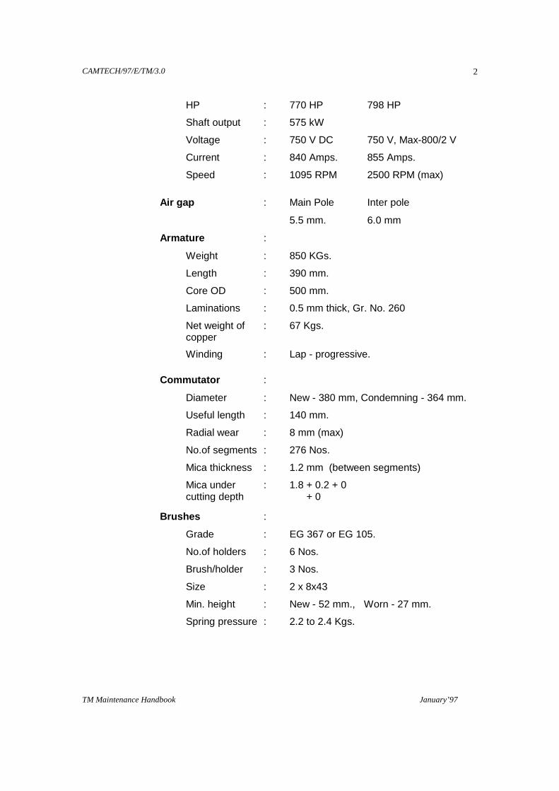
HP : 770 HP 798 HP
Shaft output : 575 kW
Voltage : 750 V DC 750 V, Max-800/2 V
Current : 840 Amps. 855 Amps.
Speed : 1095 RPM 2500 RPM (max)
Air gap : Main Pole Inter pole
5.5 mm. 6.0 mm
Armature :
Weight : 850 KGs.
Length : 390 mm.
Core OD : 500 mm.
Laminations : 0.5 mm thick, Gr. No. 260
Net weight of : 67 Kgs. copper
Winding : Lap - progressive.
Commutator :
Diameter : New - 380 mm, Condemning - 364 mm.
Useful length : 140 mm.
Radial wear : 8 mm (max)
No.of segments : 276 Nos.
Mica thickness : 1.2 mm (between segments)
Mica under : 1.8 + 0.2 + 0 cutting depth + 0
Brushes :
Grade : EG 367 or EG 105.
No.of holders : 6 Nos.
Brush/holder : 3 Nos.
Size : 2 x 8x43
Min. height : New - 52 mm., Worn - 27 mm.
Spring pressure : 2.2 to 2.4 Kgs.

CAMTECH/97/E/TM/3.0
TM Maintenance Handbook January’97
3
Gear Ratio : 62:15, 58:21
Permanent shunt : 5 %
Bearing
Type : CE -NJ 318, PE -NU 328
Make : SKF, NBC, FAG, NORMA
Lubrication : Shell Albania EP 2.
Clearance : Diametrical - CE 0.30 mm - PE 0.035 mm
1.3 POWER SUPPLY ARRANGEMENT
All the six Nos. of TMs on the locomotive are fed through RSI unit (Rectifier
unit). There are three types of arrangements which can be made to supply the
power to these motors as shown in figures accordingly the motors can be
grouped in three ways i.e. 3s-2p, 2s-3p or 6p
1.3.1 Series-Parallel Combination (3s-2p)
Motors on axles 1-4-2 are in series, similarly Motors on axles 3-6-5 are in se-ries. These two series groups are con-nected in parallel. Though this combi-nation is more economic but in case of failure of any one of the TM, the loco-power drastically reduces by 50% which is the main draw back of this combination. This combination of Tration Motors is therefore being phased out gradually.
1.3.2 Parallel Combination (2s-3p)
This is also called `P’ combination. Gen-
erally motors on axles 1, 4 are in series,
similarly Motors on axles 2,5 and accord-
ingly motors on axles 3&6 are in series.
One group has to be isolated in case of any
TM problem, which reduces power of the
locomotive by 33%.
Figure 1.1
Figure 1.2
CAMTECH/97/E/TM/3.0
TM Maintenance Handbook January’97
4
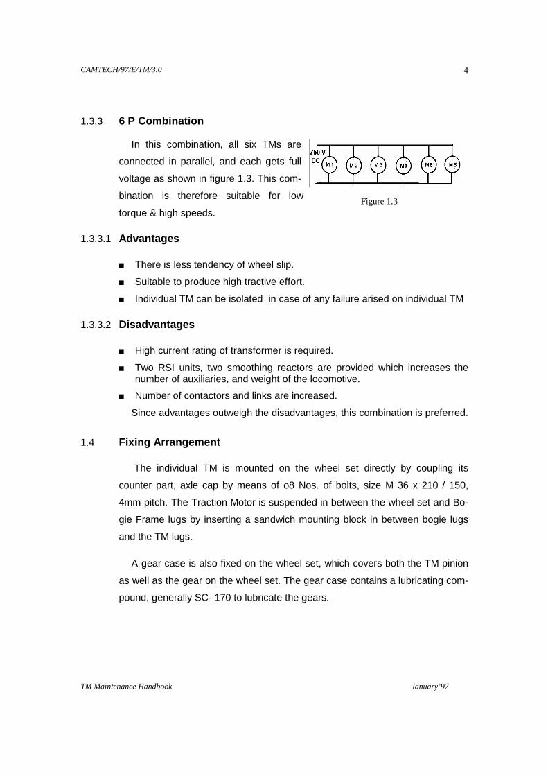
1.3.3 6 P Combination In this combination, all six TMs are
connected in parallel, and each gets full
voltage as shown in figure 1.3. This com-
bination is therefore suitable for low
torque & high speeds.
1.3.3.1 Advantages
There is less tendency of wheel slip.
Suitable to produce high tractive effort.
Individual TM can be isolated in case of any failure arised on individual TM
1.3.3.2 Disadvantages
High current rating of transformer is required.
Two RSI units, two smoothing reactors are provided which increases the number of auxiliaries, and weight of the locomotive.
Number of contactors and links are increased.
Since advantages outweigh the disadvantages, this combination is preferred.
1.4 Fixing Arrangement
The individual TM is mounted on the wheel set directly by coupling its
counter part, axle cap by means of o8 Nos. of bolts, size M 36 x 210 / 150,
4mm pitch. The Traction Motor is suspended in between the wheel set and Bo-
gie Frame lugs by inserting a sandwich mounting block in between bogie lugs
and the TM lugs.
A gear case is also fixed on the wheel set, which covers both the TM pinion
as well as the gear on the wheel set. The gear case contains a lubricating com-
pound, generally SC- 170 to lubricate the gears.
Figure 1.3

CAMTECH/97/E/TM/3.0
TM Maintenance Handbook January’97
5
1.5 CONSTRUCTIONAL FEATURES
The traction motor TAO-659 has the following main parts:
1.5.1 Stator Frame
This is a cast steel
magnet frame
consisting of main
poles and interpoles
fixed to it. On the
Commutator side,
opening has been
provided for upper air
inlets (from MVMT)
and lower inspection
cover. The terminal
box is situated above
the axle side. To the backside of frame, two lugs are extended for suspending
the TM in bogie frame by means of inserting a sandwich-mounting block in
between the TM lugs & the bogie lugs. For securing the gear case, this frame is
also facilitated two eyes on the top & bottom and two inside threaded holes at
the pinion end as shown in figure 1.4. The another counter part of the frame is
axle cap, which facilitated the axle bearings (half of each PE & CE) oil pumps,
wickpads etc. The two oil wicks containers are in communication with each
other through an oil passage situated at the upper part of the axle cap. Oil is
supplied from an axle driven oil pump in central oil sump; oil delivery being
assured in both running directions. Any surplus oil of the containers returns to
the pump. Axle cap is also having an arrangement for providing earthing
shunts, which allows the return current to rail through the axle & wheel
assembly.
Figure 1.4

CAMTECH/97/E/TM/3.0
TM Maintenance Handbook January’97
6
1.5.2 Armature
It is the rotating member of the
motor, consisting of a number of cop-
per conductors suitably placed and
connected so as to form a closed
winding. The armature consisting of
slots, teeth, winding and the core is
shown in figure 1.5. The rotating ar-
mature is subjected to an alternating
flux varying at frequency of 20 to 50
Hz, depending upon the number of
poles and speed (f= PN/120), which gives rise to eddy currents and hysteresis
losses in the armature core and teeth. The eddy-current loss is directly propor-
tional to the square of the thickness. Therefore the armature is built up of 0.4 to
0.5 mm thick magnetic steel laminations, insulated from one another by a thin
layer of class `H’ varnish. The punching are keyed to armature shaft. Longitudi-
nal ventilating ducts are provided in the core to improve the cooling.
Assembled hot in a press, the laminations are maintained by a cast steel
armature head at pinion end, and at other, by the cast steel armature sleeves
retained on the shaft by set ring and retaining ring at pinion end.
1.5.2.1 Armature Winding
It is composed of high conductivity electrolytic copper conductor, with 2/3-
tape kapton, bunch insulation being made by:
Glass mica silicon tape on the involute portion.
Nomex silicon mica wrapper in the slot portion.
The coils are maintained in the slots by moulded “Durestos” slot wedges or
laminated fibreglass slot wedges and by poly glass tape. The Choice of
armature winding is decided as following:
When the armature current is not high, a simple wave winding is preferred.
But for high armature current, number of parallel path should be more, as a
result lap winding is preferred because number of parallel path equals to
number of poles.
Figure 1.5

CAMTECH/97/E/TM/3.0
TM Maintenance Handbook January’97
7
Also depends on the no. of poles & the speed of the machine, normally the
current per parallel circuit should not exceed 250 Amps.
The armature current to be handled by the brush, should not be more than
400 Amps.
The pitch of the Commutator segment should be within a range of 5 to 10
mm. In case of TAO-659 Tration Motors , Armature winding is Lap
progressive type, with Nos. of parallel paths.
1.5.3 Armature Bearings
The armature is supported on two roller bearings mounted on cast steel end
shields. Fitment of these bearings must be in parallel. Greasing gun is used for
greasing the bearings. Labyrinth type oil seals are fitted and evacuation of used
grease is ensured by the service greasing overflow outlets.
1.5.4 Commutator
Commutator of TAO-659 TM
consisting of a 276 nos. of copper
segments, properly insulated from each
other. The function of a Commutator is
to invert DC input wave to an AC wave in
the armature winding.
It is built up of a number of small
wedge shaped segments of high
conductivity hard drawn copper, insulated
from each other by mica or micanite separators of about 0.8 mm thickness to
avoid jumping of brushes and resultant sparking. The Commutator segments are
assembled over an insulated steel cylinder of V-cone shaped. The assembly is
forced and press fitted on the shaft.
The ends of the armature coils are directly soldered to the Commutator
base, when the Commutator diameter is approximately equal to the armature
diameter. However, when the difference in the two diameters is appreciable as
in case of TAO-659 Traction Motors, the ends of the armature coils are con-
nected to the Commutator with the half of risers shown in figure 1.6.
1.5.4.1 Commutation
Figure 1.6
CAMTECH/97/E/TM/3.0
TM Maintenance Handbook January’97
8
The emf generated in the armature conductor of DC machine is alternating
and as such the current in a particular conductor is in one direction when the
conductor is moving under the north pole and in the reverse direction, when it is
moving under south pole. This reversal of current in a coil will take place when
the two Commutator segments to which the coil is connected are being short-
circuited by a brush. The process of reversal of current in a coil is termed
`COMMUTATION’.
The reversal of high current in an inductive circuit in such a short time may
pose certain difficulties causing considerable sparking at two brushes. From the
physical considerations, the commutation process is of complex nature, in
which various mechanical, thermal, electrochemical & electromagnetic factors
are closely interwoven.
The rapid reversal of current in the armature core sets up a self-induced emf,
generally called reactance voltage, which tends to delay the current reversal in
the coil. As a result, the current in the short circuit coil does not attain its full
value in the reverse direction by the end of short circuit. This is the basic cause
of sparking at Commutator. Hence the reactance voltage is mainly responsible
for sparking at the brushes of DC machines.
1.5.4.2 Method of improving Commutation
Sparking at the brushes can be minimised with an improvement in the
commutation by providing special commutating poles (interpoles), placed mid
way between the main poles and wound with comparatively few turns and
connected in series with the armature winding. For DC generators, their polarity
should be the same as the next main pole in the direction of rotation. For DC
motors, the polarity should be opposite to above .The field produced by the
interpole winding opposes the armature field.
The mmf developed by the interpole must be stronger than the armature
mmf in the neutral zone, because this mmf has to cancel the armature mmf and
in addition induce an emf in short circuited coil which opposes reactance volt-
age and the voltage drop at the brushes. If the mmf on the interpole is too
weak, it would lead to retarded commutation and if it is too strong accelerated
commutation is achieved. In both the cases sparking will be occur at brushes
CAMTECH/97/E/TM/3.0
TM Maintenance Handbook January’97
9
and Commutator. Hence, the mmf on the interpole must be estimated correctly,
so as to achieve sparkles commutation.
Use of high reactance brushes (carbon brushes) and using brushes wide
enough to cover two or three segments, further improve commutation.
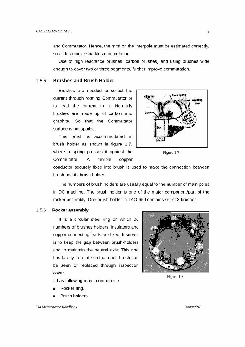
1.5.5 Brushes and Brush Holder
Brushes are needed to collect the
current through rotating Commutator or
to lead the current to it. Normally
brushes are made up of carbon and
graphite. So that the Commutator
surface is not spoiled.
This brush is accommodated in
brush holder as shown in figure 1.7,
where a spring presses it against the
Commutator. A flexible copper
conductor securely fixed into brush is used to make the connection between
brush and its brush holder.
The numbers of brush holders are usually equal to the number of main poles
in DC machine. The brush holder is one of the major component/part of the
rocker assembly. One brush holder in TAO-659 contains set of 3 brushes.
1.5.6 Rocker assembly
It is a circular steel ring on which 06
numbers of brushes holders, insulators and
copper connecting leads are fixed. It serves
is to keep the gap between brush-holders
and to maintain the neutral axis. This ring
has facility to rotate so that each brush can
be seen or replaced through inspection
cover.
It has following major components:
Rocker ring.
Brush holders.
Figure 1.7
Figure 1.8

CAMTECH/97/E/TM/3.0
TM Maintenance Handbook January’97
10
Insulators - These are glass bonded mica insulators.
Connecting leads- made of electrolytic grade copper rods.
Final assembly.
All six brush holders are positioned exactly 60° apart, on the rocker ring with
the help of insulator. The concentricity of all the inner faces of the brush holders
with respect to diameter of the rocker ring should be within required limit. The
maximum error allowed in the pitch of leading edges of the carbon brushes is
0.1 mm. which works out to 0.029 degrees (0 degree, 1 minute, 47 seconds)
maximum angular deviation from 60°. This is permissible between the centre
lines of any two adjacent brushes.
1.5.7 End shields
The TM TAO -659 has two nos. of cast steel end shields at both the ends i.e.
at pinion end & at Commutator end. Both are mounted with roller bearings for
supporting the armature.
A grease nipple and bearing covers are also facilitated for greasing the
bearings during maintenance schedule and for protecting the bearings from
dust & foreign bodies.
1.5.8 Pinion
It is made of high-speed carbon steel, shrinkly fitted on the armature head of
TM. This pinion has 15 or 21 teeth and is directly geared up with the gear of the
wheel set and responsible for driving the wheel set and ultimately the
locomotive.
1.6 WORKING PRINCIPLE OF D.C. MOTOR
The field system is stationary supplied
through main poles on stator frame. The
armature winding is a closed winding through
the Commutator, which is supplied through the
brushes, which are placed along the neutral/axis
on the Commutator. The mmf produced by the
Figure 1.9
CAMTECH/97/E/TM/3.0
TM Maintenance Handbook January’97
11
field (Ff) along the magnetic axis while the current flowing through the armature
produces an mmf (Fa) directed along the brush axis. The two mmfs are in
space quardrature and occur simultaneously in the motor. They react with each
other and develop a torque under whose action the armature rotates. A voltage
induced in armature can be determined by the Fleming’s left-hand rule. The
mmfs and the direction of rotation of the armature are illustrated in figure 1.9.
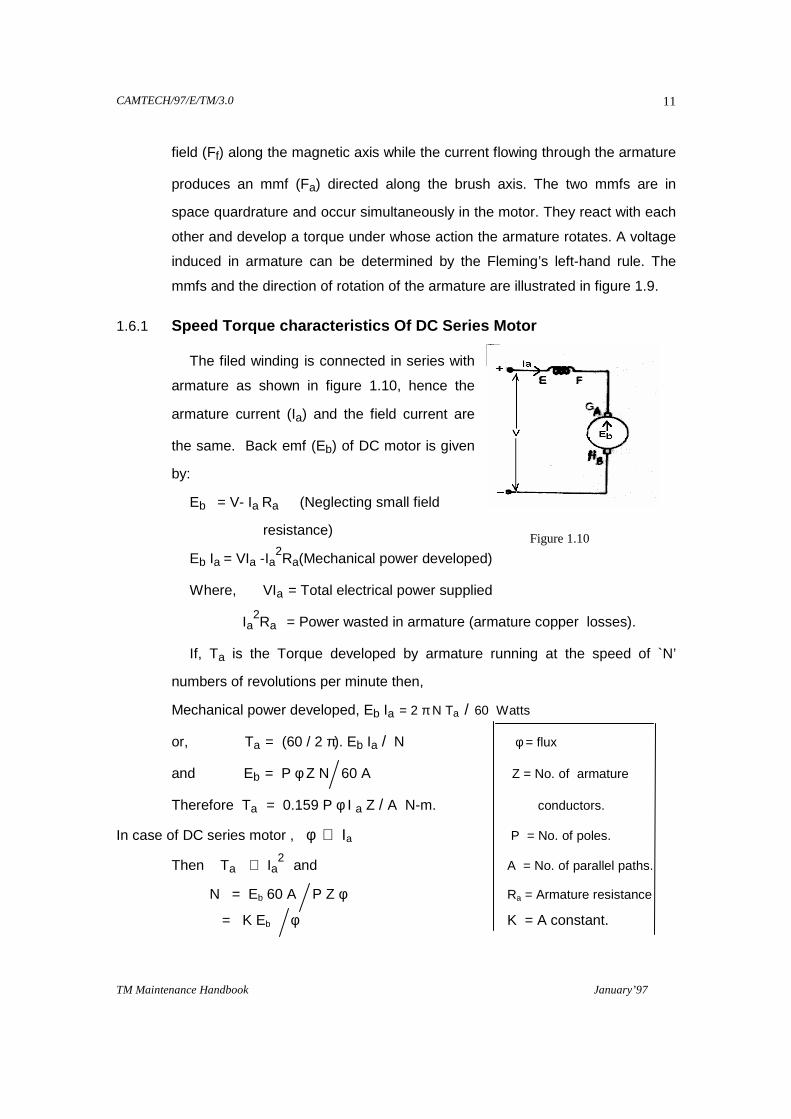
1.6.1 Speed Torque characteristics Of DC Series Motor
The filed winding is connected in series with
armature as shown in figure 1.10, hence the
armature current (Ia) and the field current are
the same. Back emf (Eb) of DC motor is given
by:
Eb = V- Ia Ra (Neglecting small field
resistance)
Eb Ia = VIa -Ia2Ra(Mechanical power developed)
Where, VIa = Total electrical power supplied
Ia2Ra = Power wasted in armature (armature copper losses).
If, Ta is the Torque developed by armature running at the speed of `N’
numbers of revolutions per minute then,
Mechanical power developed, Eb Ia = 2 π N Ta / 60 Watts
or, Ta = (60 / 2 π). Eb Ia / N φ = flux
and Eb = P φ Z N 60 A Z = No. of armature
Therefore Ta = 0.159 P φ I a Z / A N-m. conductors.
In case of DC series motor , φ ∝ Ia P = No. of poles.
Then Ta ∝ Ia2 and A = No. of parallel paths.
N = Eb 60 A P Z φ Ra = Armature resistance
= K Eb φ K = A constant.
Figure 1.10

CAMTECH/97/E/TM/3.0
TM Maintenance Handbook January’97
12
At light loads Ia and hence φ will be
quite low and Eb will be high, therefore
`N’ may become quite high. However
as the load on the motor increases,
speed will decrease rapidly & with
further increase in armature current,
the increase in flux is quite small
because of saturation effect & hence
the curve flattens out (as shown in
figure 1.11).
Similarly we see that at low speeds, high torque can be obtained, and with
increase in speed, less torque is developed.
This characteristics is particularly useful for
traction purposes, because requirement of
torque if high at starting, whereas once
the train is in motion the low friction
resistance reduces the torque requirement
for a given load.
This characteristics (as shown in figure 1.12) clearly indicated that DC series
motor should never be started without load, which is the case in traction.
Figure 1.11
Figure 1.12
CAMTECH/97/E/TM/3.0
TM Maintenance Handbook January’97
13
CHAPTER 2
INSPECTION SCHEDULE
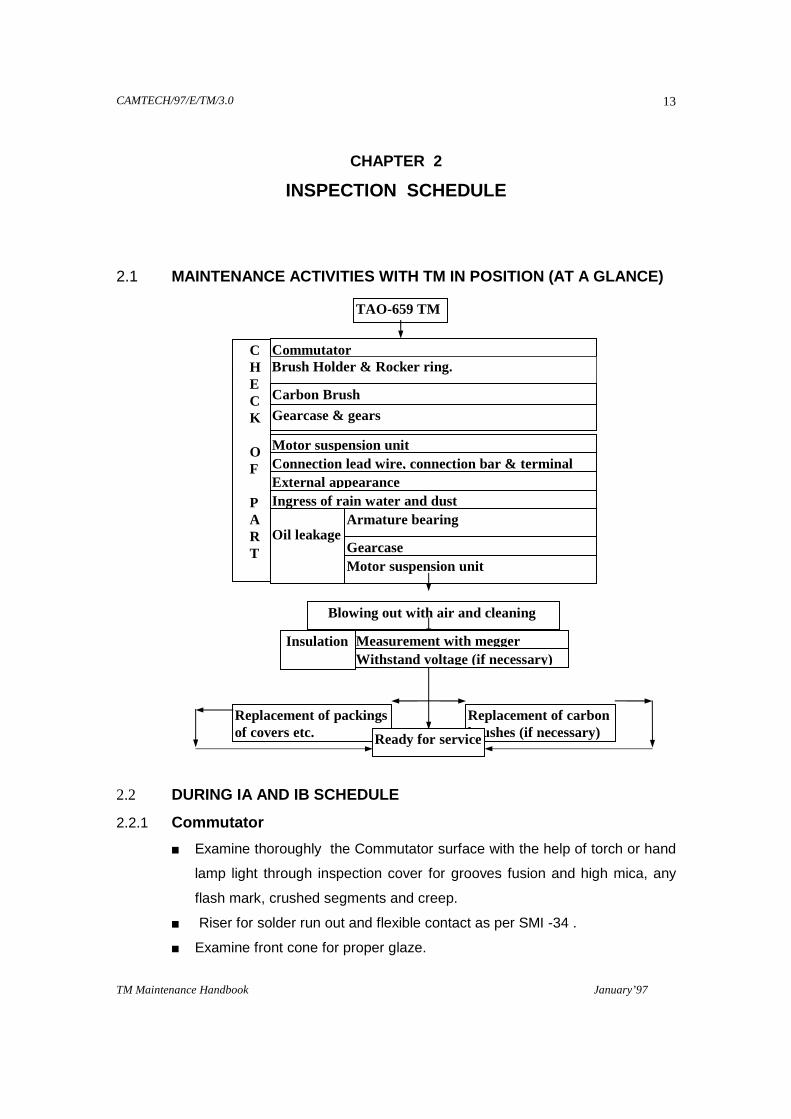
2.1 MAINTENANCE ACTIVITIES WITH TM IN POSITION (AT A GL ANCE)
2.2 DURING IA AND IB SCHEDULE
2.2.1 Commutator
Examine thoroughly the Commutator surface with the help of torch or hand
lamp light through inspection cover for grooves fusion and high mica, any
flash mark, crushed segments and creep.
Riser for solder run out and flexible contact as per SMI -34 .
Examine front cone for proper glaze.
TAO-659 TM
C H E C K O F P A R T
Commutator Brush Holder & Rocker ring.
Carbon Brush
Gearcase & gears
Motor suspension unit Connection lead wire, connection bar & terminal External appearance Ingress of rain water and dust Oil leakage
Armature bearing
Gearcase Motor suspension unit
Blowing out with air and cleaning
Measurement with megger Withstand voltage (if necessary)
Insulation
Replacement of packings of covers etc.
Replacement of carbon brushes (if necessary) Ready for service

CAMTECH/97/E/TM/3.0
TM Maintenance Handbook January’97
14
Polish /clean complete Commutator surface by taking slight movement of
locomotive.
2.2.2 Brush Gear
Measure and record size of all carbon brushes (condemn limit 27 mm.) .
Examine brush holder insulators for proper glaze.
2.2.3 Inspection Cover
Ensure existence, condition and proper fitment of both top and bottom
inspection cover.
2.2.4 Arcing Horns
Condition of arcing horns & clearance
Check flexible assembly. 2.3 DURING IC SCHEDULE
In addition to above, the following points also to be inspected and work to be carried out during IC schedule.
2.3.1 Commutator
Clean commutator with sprit / petrol and cloth. Inspect visually commutator end banding and risers for any abnormality.
2.3.2 Brush Gear
Measure brush box to commutator clearance and adjust if required.
Measure spring pressure on brushes, 2.2 to 2.4 kgs. and check up condition.
Examine the condition of pig tails and replace carbon brushes if reached to condemning size.
Check up spring pins by hand .
Rotate rocker arm of all six TMs and Check brush holders and insulators.
Rocker ring should be unlocked first, using the tool, as shown in figure 2.1. 2.3.3 Arcing Horns
Figure 2.1
CAMTECH/97/E/TM/3.0
TM Maintenance Handbook January’97
15
Check arcing ring for flash marks.
Clean V- cone.
2.3.4 Terminals
Examine outgoing interpole leads for any cracks etc.
Check the cover gasket of terminal cover , replace if required. Check connections tightness.
Check tightness of wooden cleats.
Check the gasket of inspection cover and ensure air tightness.
Check setting of inter pole and field both .
Meggering of TMs.
Greasing of both end bearing
CAMTECH/97/E/TM/3.0
TM Maintenance Handbook January’97
16
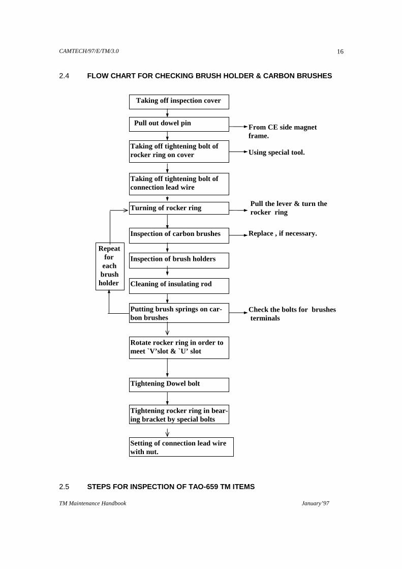
2.4 FLOW CHART FOR CHECKING BRUSH HOLDER & CARBON BRUSH ES 2.5 STEPS FOR INSPECTION OF TAO-659 TM ITEMS
Taking off inspection cover
Pull out dowel pin
Taking off tightening bolt of rocker ring on cover
Taking off tightening bolt of connection lead wire
Turning of rocker ring
Inspection of carbon brushes
Inspection of brush holders
Cleaning of insulating rod
Putting brush springs on car-bon brushes
Rotate rocker ring in order to meet `V’slot & `U’ slot
From CE side magnet frame.
Pull the lever & turn the rocker ring
Check the bolts for brushes terminals
Repeat for each brush holder
Tightening Dowel bolt
Tightening rocker ring in bear-ing bracket by special bolts
Setting of connection lead wire with nut.
Using special tool.
Replace , if necessary.
CAMTECH/97/E/TM/3.0
TM Maintenance Handbook January’97
17
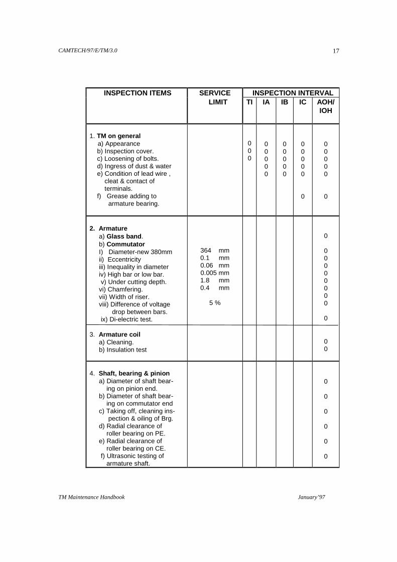
INSPECTION ITEMS SERVICE INSPECTION INTERVAL LIMIT TI
IA IB IC AOH/ IOH
1. TM on general a) Appearance b) Inspection cover. c) Loosening of bolts. d) Ingress of dust & water e) Condition of lead wire , cleat & contact of terminals. f) Grease adding to armature bearing.
0 0 0
0 0 0 0 0
0 0 0 0 0
0 0 0 0 0 0
0 0 0 0 0
0
2. Armature a) Glass band . b) Commutator I) Diameter-new 380mm ii) Eccentricity iii) Inequality in diameter iv) High bar or low bar. v) Under cutting depth. vi) Chamfering. vii) Width of riser. viii) Difference of voltage drop between bars. ix) Di-electric test. 3. Armature coil a) Cleaning. b) Insulation test
364 mm 0.1 mm 0.06 mm 0.005 mm 1.8 mm 0.4 mm
5 %
0
0 0 0 0 0 0 0 0
0
0 0
4. Shaft, bearing & pinion a) Diameter of shaft bear- ing on pinion end. b) Diameter of shaft bear- ing on commutator end c) Taking off, cleaning ins- pection & oiling of Brg. d) Radial clearance of roller bearing on PE. e) Radial clearance of roller bearing on CE. f) Ultrasonic testing of armature shaft.
0
0
0
0
0
0
CAMTECH/97/E/TM/3.0
TM Maintenance Handbook January’97
18
INSPECTION ITEMS SERVICE INSPECTION INTERVAL LIMIT TI
IA IB IC AOH/ IOH
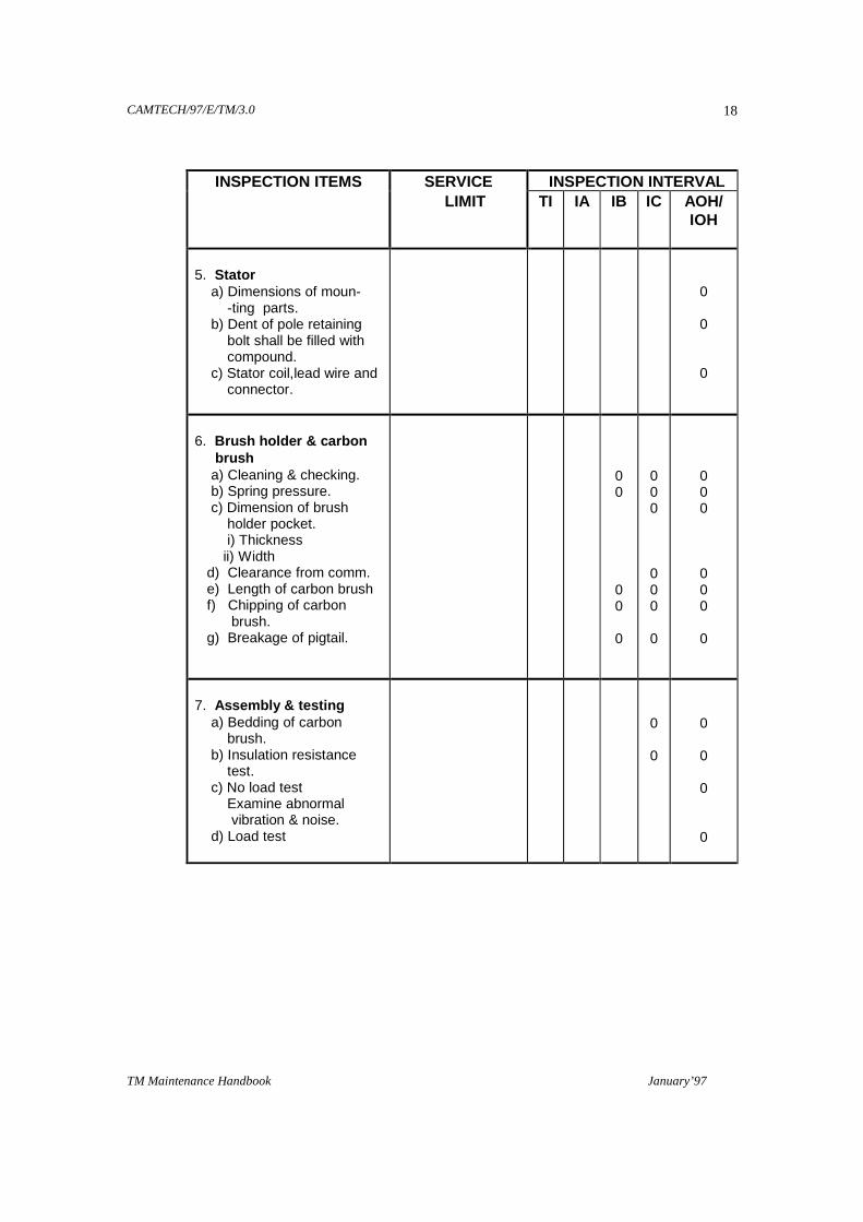
5. Stator a) Dimensions of moun- -ting parts. b) Dent of pole retaining bolt shall be filled with compound. c) Stator coil,lead wire and connector.
0 0 0
6. Brush holder & carbon brush a) Cleaning & checking. b) Spring pressure. c) Dimension of brush holder pocket. i) Thickness ii) Width d) Clearance from comm. e) Length of carbon brush f) Chipping of carbon brush. g) Breakage of pigtail.
0 0
0 0
0
0 0 0 0 0 0 0
0 0 0 0 0 0 0
7. Assembly & testing a) Bedding of carbon brush. b) Insulation resistance test. c) No load test Examine abnormal vibration & noise. d) Load test
0 0
0 0 0 0
CAMTECH/97/E/TM/3.0
TM Maintenance Handbook January’97
19
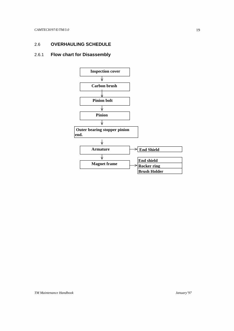
2.6 OVERHAULING SCHEDULE 2.6.1 Flow chart for Disassembly en
Inspection cover
Carbon brush
Pinion bolt
Pinion
Outer bearing stopper pinion end.
Armature
Magnet frame
End Shield
End shield Rocker ring
Brush Holder

CAMTECH/97/E/TM/3.0
TM Maintenance Handbook January’97
20
2.7 DISASSEMBLY 2.7.1 Disassembly of Armature
Remove the carbon brush from the brush holder.
After removing carbon brushes, wind
a press board on the Commutator for preventing the Commutator sur-face from being scratched.
Dismount the bearing cover from the
end shield utilising the taped hole for pulling out.
Dismount the outer bearing stopper and thrust collar of roller bearing from
the armature shaft.
Remove all the bolts tightening the bearing bracket i.e. PE end shield by screwing Hex Hd. bolts M-20 into taped holes in the end shield and dis-mount the end shield.
Fit the armature lifting hook on the armature shaft at pinion side, lift the ar-
mature by crane as shown in figure 2.2, screw the bolts in the taped holes of end shield and turn the armature slowly till the spigot joint & magnet frame comes off; and while checking to see that the armature is turned smoothly, dismount the armature alongwith PE end shield from the stator.
Place the dismounted armature
onthe table with laid down. Lay the armature on a wooden
table with it supported by core face, as shown in figure 2.3.
Never support the armature with
the coil, glass bind part or Com-mutator part.
2.7.2 Disassembly of End shield (PE) (Bearing bracket)
For disassembling the end shield from dismounted armature, insert a steel bar (20 mm in dia) inside the end shield bolt hole and extract the end shield crosswise, lifted and supported by crane.
Figure 2.2
Figure 2.3

CAMTECH/97/E/TM/3.0
TM Maintenance Handbook January’97
21
2.7.3 Disassembly of Commutator side End shield
Dismount the CE, end shield together with outer ring of roller bearing (bear-ing bracket) from the magnet frame utilising the tapped hole for pulling out. Pay full attention when handling the bearing bracket.
Remove the rocker ring from the magnet frame.
Write serial number with white paint on rocker ring and magnet frame.
2.7.4 Disassembly of Armature Bearing 2.7.4.1 Pinion End Remove PE end shield from the armature, the following parts are fitted on
armature shaft pinion side, i.e. inner bearing stopper, bearing inner ring and outer bearing stopper.
After dismounting the outer bearing stopper, dismount the inner bearing
stopper and bearing inner ring simultaneously by using the exclusive tools as shown in figures 2.4 & 2.5.
1 - HOOK , 2 - KEEPER PLATE, 3 - NUT, 4- DOUBLE END STUDS 5 - SUPPORT DISK, 6 - NUT M 24, 7 - RAM WITH OIL POWER PUMP 8 - BOLT M 24x40 TOOLS ASSEMBLING PROCEDURE :
Figure 2.4

CAMTECH/97/E/TM/3.0
TM Maintenance Handbook January’97
22
1. Set hooks 1 on inner bearing stopper.
2. Fix hooks 1 by keeper plate 2
3. Screw double-end studs 4 in hooks 1
4. Set support disk 5 on Ram, set nut 3 on piston.
5. Fix support disk 5 by double-end studs 4 & nuts 6
6. Press piston with handling oil power pump.
1 - NUT, 2 - PULLER, 3 - ABSORBER, 4 - DISTANCE PIECE 5 - SUPPORT DISK, 6 - STAND, 7 - RAM WITH OIL POWER PUMP TOOLS ASSEMBLING PROCEDURE : 1. Set Ram into stand 6
2. Screw support disk 5 on Ram.
3. Put absorber 3 & distance piece 4 on support disk 5
4. Set puller 2 on outer race.
5. Put together outer race & puller 2 on distance piece
6. Press piston up through puter race & set nut 1 on piston.
7. Catch rollers by puller 2
8. Press piston downward with handling oil power pump.
Figure 2.5

CAMTECH/97/E/TM/3.0
TM Maintenance Handbook January’97
23
2.7.4.2 Commutator End Similarly dismount the bearing inner ring, inner bearing stopper and bearing
outer ring at the same time, after removing CE end shield by exclusive tool according the above procedure.
2.7.5 Cleaning of Armature Bearing To clean the dismounted armature bearings, put them into a vessel contain-
ing kerosene heated upto about 60° without degreasing and leave them as they are in kerosene for more than 10 minutes. After that, blow away sticking grease with compressed air. Repeat the procedures more than twice, and then, wash the bearings finally with a clean kerosene, and blow away adhering kerosene completely with air.
For the final washing, always use new kerosene and do not use heavily oxi-
dised or foul one. Wash hands with a degreasing agent such as ethyl alcohol carefully for preventing the bearings from getting rusty.
2.7.6 Checking of Armature Bearings
Check visually for roughness, scratch, bruise, discoloration, rust etc. on in-ner & outer race too.
Check while moving the rollers for wear of retainer, looseness of rivets and make sure that there is no abnormality.
If any abnormality observed in either inner or outer ring, replace with new set of bearings.
Check for inner & outer ring of same serial number. 2.7.7 Maintenance of Rocker equipment Disassemble the brush holders, insulators, rocker leads and rocker ring. In-
spect them visually check the arcing stud and knock pins, polish the insulating rods. Measure the brush spring pressure and length of carbon brushes. The fol-lowing points should be followed to improve life and service of the rocker assem-bly during overhauling as shown in figure 2.6.
Remove old insulation of the rocker
leads and taped with kapton tape, GMGS tape and fibre glass tape ac-cordingly.
Provide Kapton tape & Nomex paper-between rocker cleats.
Pre heat the leads at 150°C for four hours.
Figure 2.6
CAMTECH/97/E/TM/3.0
TM Maintenance Handbook January’97
24
Provide Silconite `E-233’ on the rocker leads & bake it at 180°C for four hours or at 150 °C for eight hours.
Tape should be cleaned for its smoothness by the sandpaper.
Measure the tension of every spring of brush holder. Tension should be 2.4 to 2.2 Kg.
Revolving it in every schedule should clean rocker. 2.7.8 Maintenance of Commutator The necessity of reworking the Commutator surface is determined depend-
ing on its condition and the judgement. It must be judged observing the condi-tion of Commutator surface carefully and can be maintained as following.
2.7.8.1 Grindstone Applying “Grindstone” must rework the commutator exhibiting the following
conditions:
Where the Commutator surfaces is heavily blackened.
Where the Commutator surfaces is rough owing to minor flashover.
Procedure:
Apply a grindstone to the Commutator in the condition where the armature
has been assembled in the motor. The armature to be put on a lathe since there is possibility of eccentricity or unevenness being caused in the Commuta-tor. Moreover, after completion of applying a grindstone, blow away the stone power with air and check carefully the groove inside between Commutator bars to be sure that there is no abnormality.
2.7.8.2 Turning of Commutator surface In case where the following conditions are recognised, apply turning to the
Commutator surface:
If eccentricity, unequally in diameter, high-bar, low-bar etc are generated in Commutator, cut the Commutator as per given table.
ITEM CORRECTIVE LIMITS AFTER TURNING
Eccentricity Not more than 0.1 mm. 0.03 mm.
Inequality in diameter
Not more than 0.06 mm. 0.006 mm.
Higher, low-bar Not more than 0.005 mm. -
CAMTECH/97/E/TM/3.0
TM Maintenance Handbook January’97
25
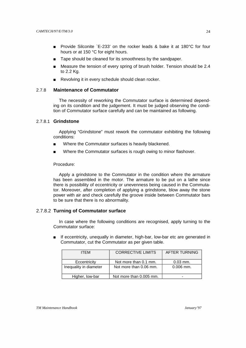
In case that stepped wear is cased in Commutator surface (when `δw’ exceeds 0.1-mm max.) shown in figure 2.7)
In case where it is impossible to rework by a grindstone because the commutator surface is heavily rough
When reusing the traction motor after a long-term storage (more than 6 months), oxide film is pro-duced on the Commutator surface causes poor commutations.
The degree of turning of Commutator surface should be judged according to the conditions of commuter surface, and it must be cut at minimum re-quired limit.
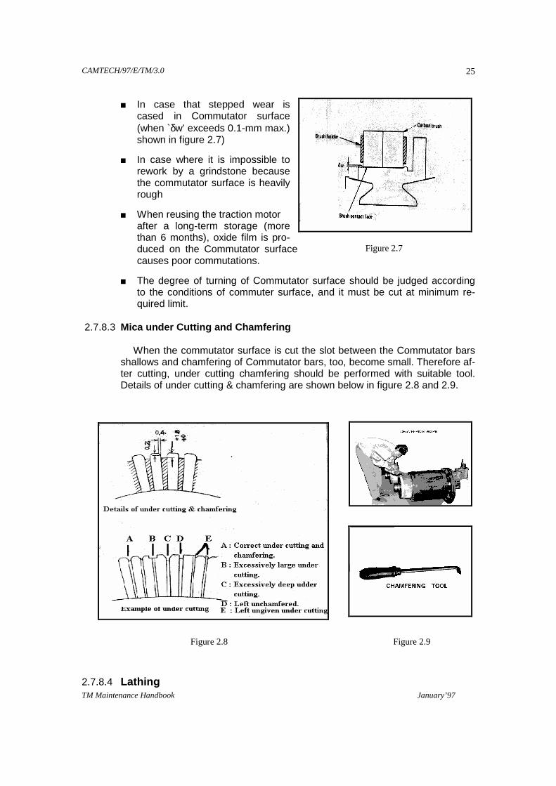
2.7.8.3 Mica under Cutting and Chamfering When the commutator surface is cut the slot between the Commutator bars
shallows and chamfering of Commutator bars, too, become small. Therefore af-ter cutting, under cutting chamfering should be performed with suitable tool. Details of under cutting & chamfering are shown below in figure 2.8 and 2.9.
2.7.8.4 Lathing
Figure 2.7
Figure 2.8 Figure 2.9

CAMTECH/97/E/TM/3.0
TM Maintenance Handbook January’97
26
When correcting the commutator surface by the lathe, align the armature shaft as shown below in figure 2.10
Rush the shaft end of armature shaft on the commutator side by the centre of lathe, align the armature shaft by using the bearing fitting portion A, on the pinion side as reference and check the shaft end on the pinion side. Apply a steady rest to the bearing-fitting portion B, on the commutator side.
2.7.8.5 Cleaning On the completion of cutting the Commutator surface, clean by blowing air
directly to it. To protect the Commutator surface from injuring, a press board and polyester tape should be winded.
2.8 REASSEMBLY OF TRACTION MOTOR - TAO 659
2.8.1 Preparation for Reassembly
Prepare all parts & tools, necessary for reassembly.
Clean all the parts.
Replace all gaskets & spring washers.
Check the bearing conditions & replace with new, if required.
Megger stator & rocker assembly and conduct High voltage & High current tests.
2.8.2 Reassembly of Roller Bearing, Rings at PE & CE
2.8.2.1 Inner ring Put the inner bearing stoppers & inner rings into the oil bath for heating upto
110 °C to 120 °C. Wipe carefully armature shaft, shrink fit inner bearing stopper & inner bearing ring on the armature shaft at both PE & CE, press
them by hand till they cool so that gap is not reduced at the stopped part of in-ner bearing. Stopper & shaft, and between inner bearing stopper & inner bear-ing ring. Similarly shrink fit the outer bearing stopper.
Figure 2.10
CAMTECH/97/E/TM/3.0
TM Maintenance Handbook January’97
27
2.8.2.1 Outer Ring
Fill the interiors of grease holding chamber of end shield and bearing outer ring with the specified amount of grease, than pressure fit the outer ring to the end shield by using exclusive tools.
Never fit the outer race while striking by hammer. Tighten the grease
covers by means of bolts. 2.8.3 Reassembly of Armature
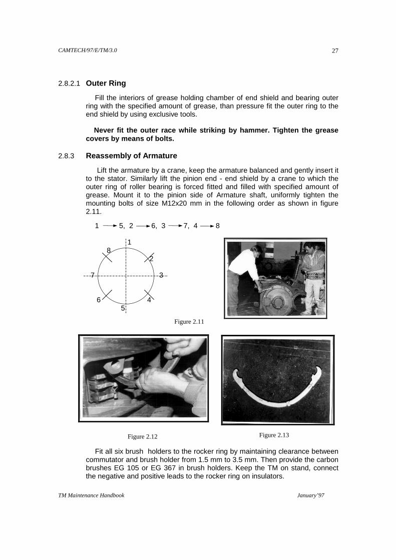
Lift the armature by a crane, keep the armature balanced and gently insert it to the stator. Similarly lift the pinion end - end shield by a crane to which the outer ring of roller bearing is forced fitted and filled with specified amount of grease. Mount it to the pinion side of Armature shaft, uniformly tighten the mounting bolts of size M12x20 mm in the following order as shown in figure 2.11.
1 5, 2 6, 3 7, 4 8 1 8 2 7 3 6 4 5
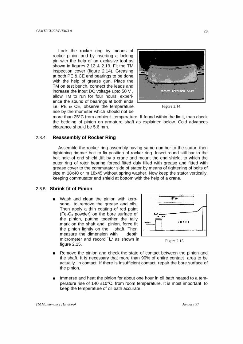
Fit all six brush holders to the rocker ring by maintaining clearance between
commutator and brush holder from 1.5 mm to 3.5 mm. Then provide the carbon brushes EG 105 or EG 367 in brush holders. Keep the TM on stand, connect the negative and positive leads to the rocker ring on insulators.
Figure 2.11
Figure 2.12 Figure 2.13
CAMTECH/97/E/TM/3.0
TM Maintenance Handbook January’97
28
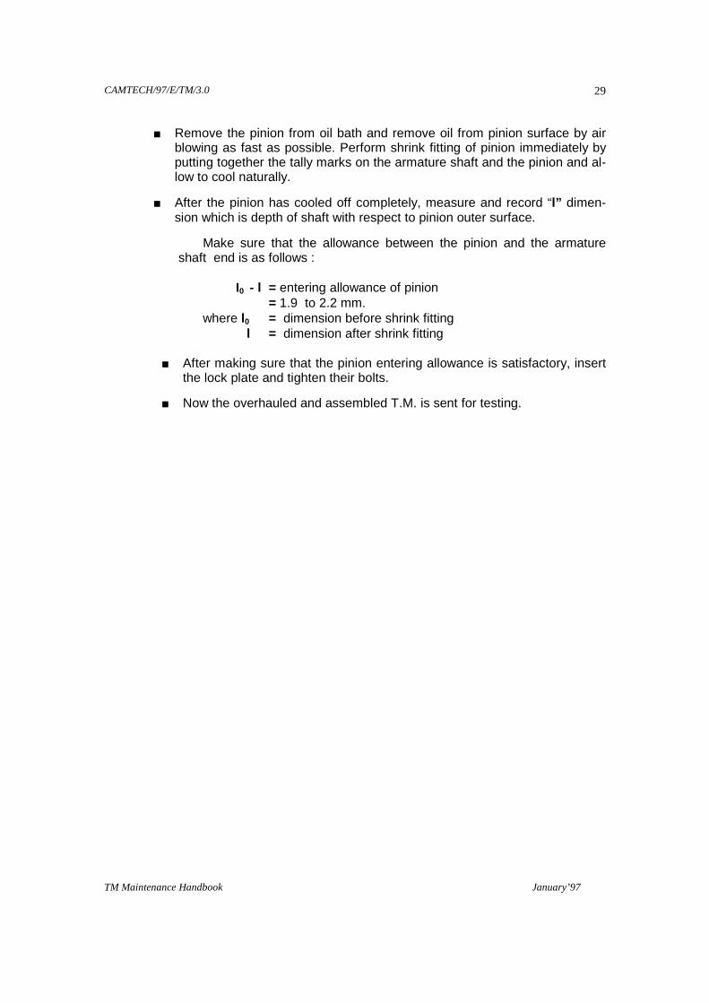
Lock the rocker ring by means of
rocker pinion and by inserting a locking pin with the help of an exclusive tool as shown in figures 2.12 & 2.13. Fit the TM inspection cover (figure 2.14). Greasing at both PE & CE end bearings to be done with the help of grease gun. Place the TM on test bench, connect the leads and increase the input DC voltage upto 50 V , allow TM to run for four hours, experi-ence the sound of bearings at both ends i.e. PE & CE, observe the temperature rise by thermometer which should not be more than 25°C from ambient temperature. If found within the limit, than check the bedding of pinion on armature shaft as explained below. Cold advances clearance should be 5.6 mm.
2.8.4 Reassembly of Rocker Ring Assemble the rocker ring assembly having same number to the stator, then
tightening rimmer bolt to fix position of rocker ring. Insert round still bar to the bolt hole of end shield ,lift by a crane and mount the end shield, to which the outer ring of rotor bearing forced fitted duly filled with grease and fitted with grease cover to the commutator side of stator by means of tightening of bolts of size m 18x40 or m 18x45 without spring washer. Now keep the stator vertically, keeping commutator end shield at bottom with the help of a crane.
2.8.5 Shrink fit of Pinion
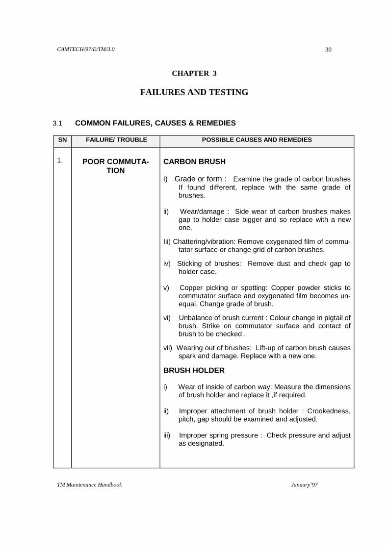
Wash and clean the pinion with kero-sene to remove the grease and oils. Then apply a thin coating of red paint (Fe2O3 powder) on the bore surface of the pinion, putting together the tally mark on the shaft and pinion, force fit the pinion lightly on the shaft. Then measure the dimension with depth micrometer and record `lo’ as shown in figure 2.15.
Remove the pinion and check the state of contact between the pinion and the shaft. It is necessary that more than 90% of entire contact area to be actually in contact. If there is insufficient contact, repair the bore surface of the pinion.
Immerse and heat the pinion for about one hour in oil bath heated to a tem-
perature rise of 140 ±10°C. from room temperature. It is most important to keep the temperature of oil bath accurate.
Figure 2.14
Figure 2.15
CAMTECH/97/E/TM/3.0
TM Maintenance Handbook January’97
29
Remove the pinion from oil bath and remove oil from pinion surface by air blowing as fast as possible. Perform shrink fitting of pinion immediately by putting together the tally marks on the armature shaft and the pinion and al-low to cool naturally.
After the pinion has cooled off completely, measure and record “l” dimen-sion which is depth of shaft with respect to pinion outer surface.
Make sure that the allowance between the pinion and the armature shaft end is as follows :
I0 - l = entering allowance of pinion = 1.9 to 2.2 mm. where l0 = dimension before shrink fitting l = dimension after shrink fitting
After making sure that the pinion entering allowance is satisfactory, insert the lock plate and tighten their bolts.
Now the overhauled and assembled T.M. is sent for testing.
CAMTECH/97/E/TM/3.0
TM Maintenance Handbook January’97
30
CHAPTER 3
FAILURES AND TESTING
3.1 COMMON FAILURES, CAUSES & REMEDIES SN FAILURE/ TROUBLE POSSIBLE CAUSES AND REMEDIES
1.
POOR COMMUTA-
TION
CARBON BRUSH i) Grade or form : Examine the grade of carbon brushes
If found different, replace with the same grade of brushes.
ii) Wear/damage : Side wear of carbon brushes makes
gap to holder case bigger and so replace with a new one.
Iii) Chattering/vibration: Remove oxygenated film of commu-tator surface or change grid of carbon brushes.
iv) Sticking of brushes: Remove dust and check gap to holder case.
v) Copper picking or spotting: Copper powder sticks to
commutator surface and oxygenated film becomes un-equal. Change grade of brush.
vi) Unbalance of brush current : Colour change in pigtail of brush. Strike on commutator surface and contact of brush to be checked .
vii) Wearing out of brushes: Lift-up of carbon brush causes spark and damage. Replace with a new one.
BRUSH HOLDER i) Wear of inside of carbon way: Measure the dimensions
of brush holder and replace it ,if required. ii) Improper attachment of brush holder : Crookedness,
pitch, gap should be examined and adjusted. iii) Improper spring pressure : Check pressure and adjust
as designated.

CAMTECH/97/E/TM/3.0
TM Maintenance Handbook January’97
31
SN FAILURE/ TROUBLE POSSIBLE CAUSES AND REMEDIES
COMMUTATOR
i) High bar, Low bar, Deformation, Ovality : Colour change, unequal oxygenated film, abnormal wear of brush may be caused a flash over. Polish the commu-tator surface with lathe.
ii) Joggle wear and roughening of surface : Polish commu-tator surface with lathe.
iii) Bad chamfering / under cutting : Reform with lathe. iv) Shorting the bars by dust and foreigner between bars : Inspect and clean the commutator bars with petrol. v) Abnormal temperature rise : Examine ventilation and
load and adjust. vi) Black bar : Adjust commutation. vii) Vibration : Examine radial as well as lateral clearances
of bearing , vibration of Bogie frame, unbalancing of armature.
2
OVERHEAT
BEARINGS i) Bruise, scratch, rust : Replace it with a new one. ii) Improper quality of grease : Replace with new and
proper grade of grease. iii) Improper fitting or clearances : Check fitment and clear-
ances and replace it with new and good bearing, if re-quired.
COILS i) Layer short, insulation breakdown: Find failure part and
repair it.

CAMTECH/97/E/TM/3.0
TM Maintenance Handbook January’97
32
SN FAILURE/ TROUBLE POSSIBLE CAUSES AND REMEDIES
3.
OTHER FAILURE
INSULATION BREAKDOWN & EARTHING
i) Coil, commutator, lead wire, inner connection, brush holder: Poor & Overaged condition of insulation, rub-bing & cutting marks on insulation. DC component to be systematically examined so as to find troubled part. Repair the damaged part according to insulation.
ii) Armature bearing grease : Examine the quality and quantity of grease. Replace if required.
iii) Gearcase :
Excess charge of gear oil : Check the oil level in gearcase and maintain as prescribed.
Bad packing and oil sealing : Replace condemned packing and oil sealing with new.

CAMTECH/97/E/TM/3.0
TM Maintenance Handbook January’97
33
3.2 TESTING OF TRACTION MOTOR TAO- 659
3.2.1 Insulation Resistance Test
Insulation resistance is measured with 1000 V megger in service, the value should be more than 1 Mega ohm. However if the value is less than 1 Mega ohm it is considered undesirable for service operation. If the insulation resis-tance drop is due to absorption of moisture, dry out must be carried out.
3.2.2 Dielectric Test
The machine if passed the dielectric test can be supposed to continue the safety operation for a considerable period without electric breakdown. The test voltage to be supplied with testing transformer and duration for various parts of TM is given below.
HIGH VOLTAGE TEST: . STATOR - 2 KV for 1 minute ROCKER - 3 KV for 1 minute.
HIGH CURRENT TEST : MAIN POLE 700 Amps for 2 minutes INTERPOLE 700 Amps for 2 minutes 3.2.3 Polarity Test
The polarity test must be done in case the field poles or the lead wires have been replaced. `N’ polarity and `S’ polarity must be distributed alternately in regular order. The pole, which attracts `S’ polarity of the magnetic needle , is `N’ polarity and the pole which attracts `N’ polarity of the magnetic needle, is `S’ polarity.
Figure 3.1
Figure 3.2
CAMTECH/97/E/TM/3.0
TM Maintenance Handbook January’97
34
3.2.3.1 Testing of Neutral Axis
Connect a voltmeter in between `N’ and `S’ pole of the TM (at brush holder), apply 50 to 60 V DC to the TM field. The voltmeter reading should stand at zero.
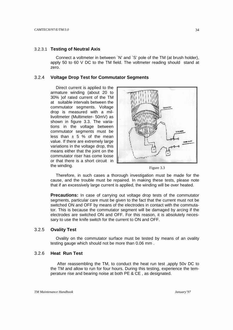
3.2.4 Voltage Drop Test for Commutator Segments Direct current is applied to the
armature winding (about 20 to 30% )of rated current of the TM at suitable intervals between the commutator segments. Voltage drop is measured with a mil-livoltmeter (Multimeter- 50mV) as shown in figure 3.3. The varia-tions in the voltage between commutator segments must be less than ± 5 % of the mean value. If there are extremely large variations in the voltage drop, this means either that the joint on the commutator riser has come loose or that there is a short circuit in the winding.
Therefore, in such cases a thorough investigation must be made for the
cause, and the trouble must be repaired. In making these tests, please note that if an excessively large current is applied, the winding will be over heated.
Precautions: In case of carrying out voltage drop tests of the commutator
segments, particular care must be given to the fact that the current must not be switched ON and OFF by means of the electrodes in contact with the commuta-tor. This is because the commutator segment will be damaged by arcing if the electrodes are switched ON and OFF. For this reason, it is absolutely neces-sary to use the knife switch for the current to ON and OFF.
3.2.5 Ovality Test
Ovality on the commutator surface must be tested by means of an ovality testing gauge which should not be more than 0.06 mm .
3.2.6 Heat Run Test After reassembling the TM, to conduct the heat run test ,apply 50v DC to
the TM and allow to run for four hours. During this testing, experience the tem-perature rise and bearing noise at both PE & CE , as designated.
Figure 3.3
CAMTECH/97/E/TM/3.0
TM Maintenance Handbook January’97
35
3.2.3.1 Testing of Neutral Axis
Connect a voltmeter in between `N’ and `S’ pole of the TM (at brush holder), apply 50 to 60 V DC to the TM field. The voltmeter reading should stand at zero.
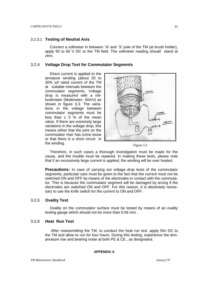
3.2.4 Voltage Drop Test for Commutator Segments Direct current is applied to the
armature winding (about 20 to 30% )of rated current of the TM at suitable intervals between the commutator segments. Voltage drop is measured with a mil-livoltmeter (Multimeter- 50mV) as shown in figure 3.3. The varia-tions in the voltage between commutator segments must be less than ± 5 % of the mean value. If there are extremely large variations in the voltage drop, this means either that the joint on the commutator riser has come loose or that there is a short circuit in the winding.
Therefore, in such cases a thorough investigation must be made for the
cause, and the trouble must be repaired. In making these tests, please note that if an excessively large current is applied, the winding will be over heated.
Precautions: In case of carrying out voltage drop tests of the commutator
segments, particular care must be given to the fact that the current must not be switched ON and OFF by means of the electrodes in contact with the commuta-tor. This is because the commutator segment will be damaged by arcing if the electrodes are switched ON and OFF. For this reason, it is absolutely neces-sary to use the knife switch for the current to ON and OFF.
3.2.5 Ovality Test
Ovality on the commutator surface must be tested by means of an ovality testing gauge which should not be more than 0.06 mm .
3.2.6 Heat Run Test After reassembling the TM, to conduct the heat run test ,apply 50v DC to
the TM and allow to run for four hours. During this testing, experience the tem-perature rise and bearing noise at both PE & CE , as designated.
APPENDIX A
Figure 3.3

CAMTECH/97/E/TM/3.0
TM Maintenance Handbook January’97
36
LIST OF RDSO’s MODIFICATIONS AND MAINTENANCE INSTR UCTIONS
SN MODIFICATION
NO. DESCRIPTION
01. RDSO/WAM4/63 Taping of leads of traction motor type TAO-659 to prevent
chafing in cleats.
02. RDSO/WAM4/67 Fixing of Neoprene gasket on the terminal box cover of
TAO-659 TM.
03. RDSO/WAM4/68 Modification to Bellow of TAO-659 TM.
04. RDSO/WAM4/90 Modification at commutator end of TAO-659 armature shaft
and the set ring.
05. RDSO/WAM4/118 Replacement of flexible contact assembly by a braided
shunt in TAO-659 TM.
06. RDSO/WAM4/158 Modification to negative connection lead of compile coil
(lead No. 13) on TAO-659 TM.
07. RDSO/WAM4/162 Modification to `L’ clamp of comm. pole of TAO-659 TM.
08. RDSO/WAM4/164 Prevention of suspension bearing oil leakage into the stator
frame.
09. RDSO/WAM4/165 Provision of thread locking compound on bolts/screws.
10. RDSO/WAM4/166 Modified support plate assembly for main pole core of TAO-
659 TM.
11. RDSO/WAM4/167 Modified adjustment punching for main pole core assembly
to TAO-659 TM.
12. RDSO/WAM4/168 Modified adjustment shim and silirite shim for commutating
pole core of TAO-659 TM.
13. RDSO/WAM4/169 Improved insulation scheme for inter-connectors of TAO-
659 TM.
14. RDSO/WAM4/174 Improved inter connector layout for TAO-659 TM.
15. RDSO/WAM4/186 Modification to the protection screen of pinion End Shield
and Air outlet of magnet frame of TAO-659 traction motor.
16. RDSO/WAM4/188 Adoption of forged armature head on the armature frame of
TAO-659 traction motors.
17. RDSO/WAM4/191 Adoption of Teflon ring in lieu of Teflon band on the ex-
CAMTECH/97/E/TM/3.0
TM Maintenance Handbook January’97
37
posed surface of V-cone of traction motor.
18. RDSO/WAM4/64 Modification (type 1) to inspection covers of TAO-659 trac-
tion motors. (Alternative modification sheet (Type 2) which
covers use of mild steel inspection cover as developed by
Gaziabad shed will be issued separately).
19. RDSO/WAM4/100 Modification to the protection screen of air outlets of TAO-
659 Traction Motor.
20. RDSO/WAM4/109 Strengthening of Inter-turn insulation of Armature of TAO-
659 Traction motor.
21. RDSO/WAM4/193 Modification to head light circuits of WAM4/WAP/
WAG5/WAG7 Electric Locomotives for working of head
lights while passing neutral section.

CAMTECH/97/E/TM/3.0
TM Maintenance Handbook January’97
38
APPENDIX B
LIST OF RDSO’s SPECIAL MAINTENANCE INSTRUCTIONS SN SMI NO. DESCRIPTION
01. ELRS/SMI/1 Fitting of nuts/bolts/screws.
02. ELRS/SMI/6 Resurfacing of commutator of TM and its amendment.
03. ELRS/SMI/13 Tightening & locking of gripping ring in TAO-659 Traction motor.
04. ELRS/SMI/14 Maintenance of terminal connections of TAO-659 TM, instruction
for tightening of the insulators.
05. ELRS/SMI/15 Sealing of tapped holes for terminal insulators of TAO-659 TM.
06. ELRS/SMI/7 Providing of essential running clearance between the axle toothed
ring of the oil pump drive of the suspension bearing of TAO-659
TM and recess provided in the suspension bearing cap.
07. ELRS/SMI/25 Millivolt drop or micro-ohm resistance test on traction motor.
08. ELRS/SMI/29 Resurfacing of commutator speed, feed, tool.
09. ELRS/SMI/31 Under cutting & chamfering of TM commutator.
10. ELRS/SMI/39 Checking of airflow in the commutator of TAO-659 TM.
11. ELRS/SMI/41 Improving the insulation of the stator internal connection of TAO-
659 TM & Field Coil Ground Insulation.
12. ELRS/SMI/42 Non-interchangeability of BHRR on TAO-659 TM.
13. ELRS/SMI/51 Bar to bar conductor resistance & equaliser resistance test on TM.
14. ELRS/SMI/53 Insulating scheme using class `H’ material at leads of armature
coils in TM.
15. ELRS/SMI/58 Special maintenance instructions for on condition monitoring of
bearings.
16. ELRS/SMI/60 Discontinuing high voltage DE test on overhauled TM.
17. ELRS/SMI/84 Procedure for drying out of TAO-659 TM.
18. ELRS/SMI/128 Tan Delta measurement of TM Armature.
19. ELRS/SMI/151 Testing of brazing joint of field coils circuits of TM type TAO-659
and HS 15250/ HS 1050 Er.
20. ELRS/SMI/160 Measurement of back lash of traction gears.
CAMTECH/97/E/TM/3.0
TM Maintenance Handbook January’97
39
21. ELRS/SMI/166 Ventilation of TAO-659 traction motor.
22. ELRS/SMI/167 Precaution while taping of bus bars and clamps of traction motors
stators.
23. ELRS/SMI/168 Copper busbar used in stator of TAO-659 traction motors in the
locomotives.
24. ELRS/SMI/170 Checks on main pole and interpole coils of TAO-659 TM.
25. ELRS/SMI/171 Fitment of “Mica-lex insulator” on TAO-659 Traction motor.
26. ELRS/SMI/174 Improved interconnector layout for TAO-659 Traction motor.
27. ELRS/SMI/180 Draft rehabilitation procedure for the mechanical portion of traction
motor type TAO-659 of BG, AC Electric Locomotives.
28. ELRS/SMI/181 Neutral setting of brush holder revolving ring of traction motor by
electrical method known as “KICK METHOD”.
CAMTECH/97/E/TM/3.0
TM Maintenance Handbook January’97
40
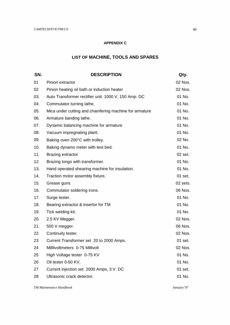
APPENDIX C
LIST OF MACHINE, TOOLS AND SPARES
SN. DESCRIPTION Qty.
01 Pinion extractor 02 Nos.
02 Pinion heating oil bath or induction heater 02 Nos.
03. Auto Transformer rectifier unit. 1000 V, 150 Amp. DC 01 No.
04. Commutator turning lathe. 01 No.
05. Mica under cutting and chamfering machine for armature 01 No.
06. Armature banding lathe. 01 No.
07. Dynamic balancing machine for armature 01 No.
08. Vacuum impregnating plant. 01 No.
09. Baking oven 200°C with trolley. 02 No.
10. Baking dynamo meter with test bed. 01 No.
11. Brazing extractor 02 set.
12. Brazing tongs with transformer. 01 No.
13. Hand operated shearing machine for insulation. 01 No.
14. Traction motor assembly fixture. 01 set.
15. Grease guns 02 sets.
16. Commutator soldering irons. 06 Nos.
17. Surge tester. 01 No.
18. Bearing extractor & insertor for TM 01 No.
19. Tick welding kit. 01 No.
20. 2.5 KV Megger. 02 Nos.
21. 500 V megger. 06 Nos.
22. Continuity tester. 02 Nos.
23 Current Transformer set 20 to 2000 Amps. 01 set.
24 Milllivoltmeters 0-75 Millivolt 02 Nos.
25 High Voltage tester 0-75 KV 01 No.
26 Oil tester 0-50 KV. 01 No.
27 Current injection set 2000 Amps, 3 V. DC 01 set.
28 Ultrasonic crack detector. 01 No.
CAMTECH/97/E/TM/3.0
TM Maintenance Handbook January’97
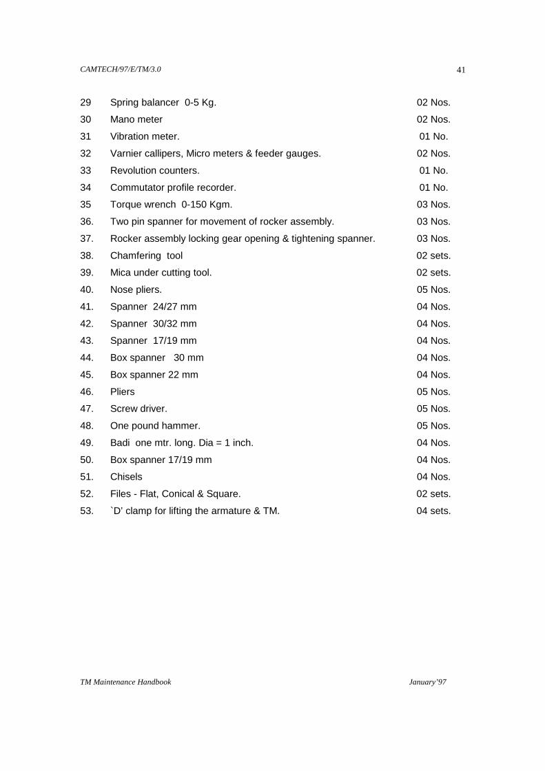
41
29 Spring balancer 0-5 Kg. 02 Nos.
30 Mano meter 02 Nos.
31 Vibration meter. 01 No.
32 Varnier callipers, Micro meters & feeder gauges. 02 Nos.
33 Revolution counters. 01 No.
34 Commutator profile recorder. 01 No.
35 Torque wrench 0-150 Kgm. 03 Nos.
36. Two pin spanner for movement of rocker assembly. 03 Nos.
37. Rocker assembly locking gear opening & tightening spanner. 03 Nos.
38. Chamfering tool 02 sets.
39. Mica under cutting tool. 02 sets.
40. Nose pliers. 05 Nos.
41. Spanner 24/27 mm 04 Nos.
42. Spanner 30/32 mm 04 Nos.
43. Spanner 17/19 mm 04 Nos.
44. Box spanner 30 mm 04 Nos.
45. Box spanner 22 mm 04 Nos.
46. Pliers 05 Nos.
47. Screw driver. 05 Nos.
48. One pound hammer. 05 Nos.
49. Badi one mtr. long. Dia = 1 inch. 04 Nos.
50. Box spanner 17/19 mm 04 Nos.
51. Chisels 04 Nos.
52. Files - Flat, Conical & Square. 02 sets.
53. `D’ clamp for lifting the armature & TM. 04 sets.

CAMTECH/97/E/TM/3.0
TM Maintenance Handbook January’97
42
APPENDIX - D
SUGGESTIONS FROM VARIOUS ELECTRIC LOCO SHEDS
Sr.No Shed/Railway Suggestions 01 ELS/JHS
CR Whenever a loco is failed, following points is to be checked: SL connections, its polarities, Manometer reading, applied voltage on each notch, RC network connections, working of Q-20 relay.
02 ELS/AQ CR
Tracing of Rocker ring can be avoided by Meggering fingers of Brush Holders which will also prevent flashing of Brush Holder. In order to prevent breakage of insulator we are using `C’ clamp may be used.
03. ELS/MGS ER
As MGS shed has experienced that the failure of Rocker ring can be avoided by cleaning of Rocker rings during every inspection schedules, inspite of IC only.
04. ELS/GOMOH ER
Check method to find reverser (inter change) of field and armature connection due to human error : a) Put reverser in idle position (either up or down). b) Switch on the battery. c) Put an insulation strip at reverser armature tips ( in other words cut off H0 side feed from armature side). d) Put test lamp across commutator side tip and earth point. e) If lamp does not glow i.e. connections are correct not to be interchanged. Time of checking : 5 to 10 minutes. Check should be carried out in every lifted loco. When to check : After the connection of motor, before closing inspection cover.
05. ELS/TKD WR
Introduce greasing of TM in every IC to compensate evapo-ration of grease during service. As a preventive measures, metal contains in grease sample in IC to be tasted in order to avoid bearing failure. During fitment of new bearing, measure free diametrical clearance, Swelling of bearing seat inner race, measure end shield bearing housing for correct fitment.
06. ELS/BZA SCR
Test to be conducted in elaborate manner. Bearing clearance like free diametrical clearance also to be checked.