mains water to buildings - mechanical...
TRANSCRIPT

Mains Water to Buildings
Water mains can be divided into three categories:
(1) trunk mains: these carry water from a source of supply
(reservoir, pumping station etc.) to a district without supplying
consumers en route.
(2) secondary mains: the distribution mains, fed from a trunk
main and supplying the consumers’ connections in the district.
(3) service pipes: the branch supplies from the secondary mains
that serve individual premises.
It is important that a drinking water supply must not be liable to
contamination.
There must be no inter-connection or cross-connection of the
supply with any other water supply.
Reflux valves or stop valves are not considered adequate to
prevent cross-contamination.
The design of water services must be arranged to prevent the
possibility of backflow or back siphonage into the water system
from any outlet.
Mains connections
Connections to a trunk or secondary main are normally only carried out by the
water supply company.
It is not normal practice to allow a service pipe to be connected to a trunk main.
Connections to secondary mains may be made under pressure to connect pipes
of 50 mm diameter and below, whereas for larger pipes a shutdown of the main
is required.
Service pipes are fitted by the water supply company from the main up to the boundary
(curtilage) of the premises to be supplied. At this point a stop valve is provided to enable
the premises' water system to be isolated from the mains

The drawing below shows a typical mains water connection to a domestic or
industrial user.
It is often normal to have a meter installed so that water suppliers will be able
to charge all customers on how much water is u
CONNECTION TO MAINS WATER SYSTEM
The service pipe to the building should be kept at about 760mm minimum
depth to avoid frost damage and damage from heavy vehicles.
The valve pit can be a purpose made plastic chamber with key operated lid.
This is sometimes situated in the footpath for ease of access if emergency
isolation is required.
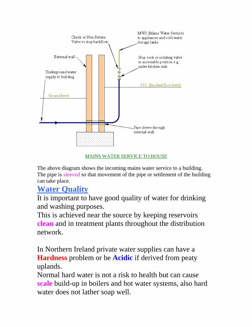
MAINS WATER SERVICE TO HOUSE
The above diagram shows the incoming mains water service to a building.
The pipe is sleeved so that movement of the pipe or settlement of the building
can take place.
Water Quality It is important to have good quality of water for drinking
and washing purposes.
This is achieved near the source by keeping reservoirs
clean and in treatment plants throughout the distribution
network.
In Northern Ireland private water supplies can have a
Hardness problem or be Acidic if derived from peaty
uplands.
Normal hard water is not a risk to health but can cause
scale build-up in boilers and hot water systems, also hard
water does not lather soap well.

Simple Chemistry of Water Water is a chemical compound. It is a liquid which boils at
100oC and freezes at 0oC, and consists of water molecules.
Each molecule contains two hydrogen atoms joined to one
oxygen atom.
It has the chemical formula H20.
It is an excellent solvent and as a result normal drinking
water contains dissolved substances such as iron (Fe),
manganese (Mn), calcium (Ca), magnesium (Mg), sulphate
(S04) and fluoride (F).
It will also contain dissolved gases including oxygen (02),
nitrogen (N) and carbon dioxide (C02).
Many of the above minerals are essential for the health and
proper growth of our bodies, but their content must be
carefully controlled as must the possible content of harmful
bacteria.
The presence of these minerals usually imparts a much
more pleasant taste to water than would be the case with
the "pure" compound.
The ability of rain to dissolve gases present in the
atmosphere produces the formation of weak acids, e.g. -
H20 + C02 H2C03, carbonic acid
H20 + S02 H2S03, sulphurous acid
H20 + C03 H2C04, sulphuric acid
On penetrating layers of soil the water dissolves
carbonates, chlorides, and sulphates of calcium and
magnesium. It may also dissolve ammonia, silica and iron
oxides. The amounts of each of these materials dissolved
depends on the thickness and type of layers through which
the water passes and on the solubility of the material. The
presence of acids in the rain water increases its ability to
dissolve many of the materials. In addition to chemicals,
water may also contain micro-organisms e.g., bacteria,
parasites, viruses and algae.
The pH of natural water varies from approximately 6.0 to
8.0 and depends on the type of rock through which the
water passes. In some areas it may be as low as 4.0, e.g.,
due to acid rain. The pH scale which ranges from 0 to 14
measures acidity and alkalinity. The lower the value the
more acidic the water.
pH less than 7 - solution is acidic
pH greater than 7 - solution is alkaline
Hard And Soft Water
Soft water contains little or no dissolved solids.
It is often brownish or yellowish in colour.
Hard water, on the other hand, will have a high calcium or magnesium salt
content.
Soft rainwater that percolates through certain types of rock strata e.g., chalk
or limestone, will become "hardened" in this way. Hard waters do not form
a lather readily which shaken with soap solution, whereas soft water lathers
easily.
The table below sub-divides hard and soft waters into several classes
depending on the hardness.
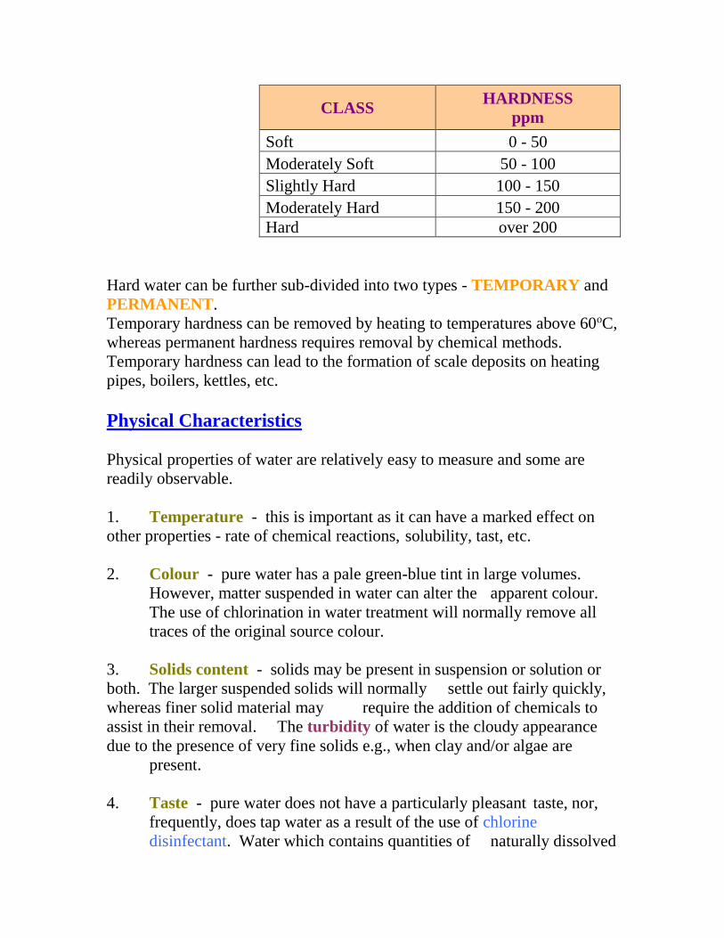
CLASS HARDNESS
ppm
Soft 0 - 50
Moderately Soft 50 - 100
Slightly Hard 100 - 150
Moderately Hard 150 - 200
Hard over 200
Hard water can be further sub-divided into two types - TEMPORARY and
PERMANENT.
Temporary hardness can be removed by heating to temperatures above 60oC,
whereas permanent hardness requires removal by chemical methods.
Temporary hardness can lead to the formation of scale deposits on heating
pipes, boilers, kettles, etc.
Physical Characteristics
Physical properties of water are relatively easy to measure and some are
readily observable.
1. Temperature - this is important as it can have a marked effect on
other properties - rate of chemical reactions, solubility, tast, etc.
2. Colour - pure water has a pale green-blue tint in large volumes.
However, matter suspended in water can alter the apparent colour.
The use of chlorination in water treatment will normally remove all
traces of the original source colour.
3. Solids content - solids may be present in suspension or solution or
both. The larger suspended solids will normally settle out fairly quickly,
whereas finer solid material may require the addition of chemicals to
assist in their removal. The turbidity of water is the cloudy appearance
due to the presence of very fine solids e.g., when clay and/or algae are
present.
4. Taste - pure water does not have a particularly pleasant taste, nor,
frequently, does tap water as a result of the use of chlorine
disinfectant. Water which contains quantities of naturally dissolved
salts, on the other hand, can be quite pleasant and sweet tasting. On
the other hand the presence of organic derived compounds (algae,
peat) can lead to an unpleasant taste.
Disinfection
This process kills off harmful organisms in water so that infection by disease
will not occur when the water is used for domestic purposes.
Generally this is achieved by chlorination that is the addition of chlorine into
the water.
The organisms in water which it may be necessary to kill by disinfection
include bacteria, viruses and protozoa.
The resistance of these organisms to the effects of disinfection varies
according to the type of organism present.
Chlorine itself which is a very strong oxidising agent and its level of dosing
must be strictly controlled otherwise the consumer will experience taste and
odour problems in the supply.
An alternative method of disinfection is by using ozone (O3).
This is, however, a very expensive method if applied on a large scale.
The ozone must be produced at the point of treatment and its production
involves the use of large quantities of electricity and its sterilizing effect is
not as persistent as that of chlorine.
Disinfection is generally the last step in the treatment process.
Other Forms Of Water Treatment
The above methods of water treatment are a general guide to the steps which
can be applied to obtain a potable water supply.
The quality of water and hence its treatment requirements can vary
dramatically depending on for example the nature of the source. Therefore,
there is not one standard system of water treatment.
Each water will have its own requirements.
A few of the other possible types of treatment are mentioned briefly below.
(a) Softening Of Water
Hard waters are produced from a source where chalk or
limestone is present.
Hard water causes a difficulty in obtaining a lather with
soap and will lead to a deposit forming in kettles or hot
water pipes.
The hard water may be softened by adding lime or sodium
carbonate which will lead to a precipitate being formed
which can be removed by filtration.
Alternatively the hard water may be passed through ion-
exchange resins which will effectively remove the
compounds which initially caused the hardness.
(b) Iron And Manganese Removal
Traces or iron and manganese can be found in many
waters.
Iron, while not being harmful in small amounts can impart
a bitter taste to water and can cause brown stains to form on
laundry. The presence of manganese can also cause taste
problems and it can react with chlorine to produce an
objectionable black slime.
A combination of chlorine and lime followed by filtration
is now the common treatment for manganese removal.
(c) Addition Of Fluoride
The addition of fluoride to the water supply has been the
subject of much public debate.
It is now generally accepted that the addition of fluoride in
small amounts to the water supply is effective in reducing
dental cavities. Fluoride in the form of hydrofluorosilic
acid can be added to the water after all other forms of
treatment have been completed.
(d) Taste, Odour And Organic Removal
Activated (i.e., heat treated) carbon, either in powdered
(PAC) or granular (GAC) form, is increasingly used in
water treatment for taste, odour and organic removal.
It can be added (as PAC) at various treatment stages but the
most common application is as filters containing GAC prior
to the disinfection stage.
(e) ph Correction
If necessary, e.g., in soft water areas, the pH of the water is
adjusted by the addition of an alkali.
Lime and calistic soda can be used.
The purpose of pH adjustment is to make the water non-
aggressive to metal pipework - both in the distribution
network and in the home.
(f) New Developments
New processes are being developed by the Water Industry e.g., sirofloc,
membrane filtration.
The Sirofloc process uses finely divided magnetite to attract particulate
(including collodial colour) material.
The magnetite itself is removed by a magnetic process.

Summary
Water can be softened by several alternative methods; base exchange
method, addition of lime-soda and use of inhibitors.
In domestic installations the base exchange method is used and water is
passed through a medium called 'zeolite', which converts the calcium salts in
the water to sodium salts.
For industrial plant, water may be softened by the addition of lime or lime-
soda. In this process large volumes of sludge needs to be removed.
Additives such as 'Calgon' may be used to stop 'fur' in boilers and these may
be regarded as inhibitors rather than true softeners.
Water contains dissolved and suspended solids which are small particles of
animal and vegetable debris. Water from chalk or from salt-bearing strata
may contain over 1000 p.p.m. (parts per million) solids, whereas water from
upland sources may contain less than 50 p.p.m. (parts per million).
The water in treatment plants is filtered and sterilised with 'chlorine' to
reduce harmful effects of bacteria in water.
The pH value of water should be considered i.e. its acidity or alkalinity. Soft
acid waters are derived from hard insoluble rocks or from peaty uplands,
they have a pH less than 7.0 and may corrode pipes and tanks unless passed
through a cylinder packed with limestone to neutralise the acidity.
Waters with a pH of more than 7.0 are alkaline and are not likely to attack
metals.
Cold Water Storage
Water storage in dwellings is usually required to meet a 24 hour demand, that is, if the supply is cut off, there will be a supply of cold water for 24 hours.
The consumption of cold water in any building depends upon;
The use to which the water is put
The number of consumers served.

The diagram below shows a typical water storage tank.
For domestic, as distinct from industrial usage, storage requirements per head of consumers are set out in Code of Practice (U.K.) CP310 and listed in the accompanying table A8 on the next page.
The practice of allocating storage per fitting or appliance is used less often since the water consumption depends more on the number of occupants than the number of appliances.
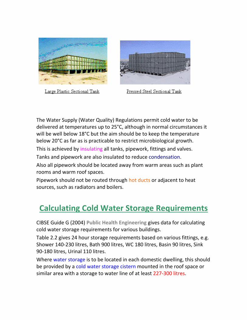
Materials Plastic and GRP (Glass Reinforced Plastic) tanks are used for small installation such as in houses.
These are manufactured as a one piece item, therefore reducing the risk of leaks.
GRP (Glass Reinforced Plastic) and galvanised steel Sectional panel tanks are used for larger installations.
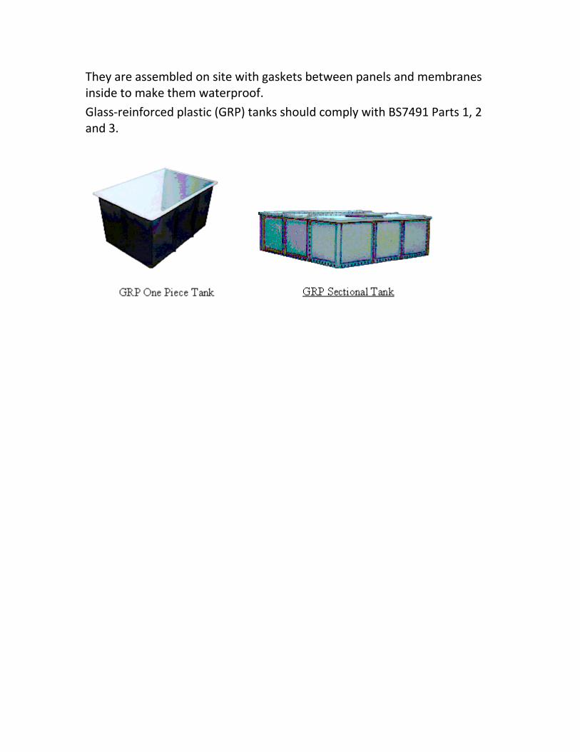
They are assembled on site with gaskets between panels and membranes inside to make them waterproof.
Glass-reinforced plastic (GRP) tanks should comply with BS7491 Parts 1, 2 and 3.

Tank Installations A typical tank is shown below.
It is important to have no stagnant areas in tanks and inlets and outlets should be at opposite ends to ensure a through flow of water as shown below.
Mains water supply
Insulation all
around tank
Typical Cold Water Storage Tank
Alternative Cold
Water Service (CWS)
outlet
Cold Water Service (CWS)
outlet at bottom ensures
better draining.
Lid
Screened vent
Screened overflow
Air gap to meet water regulations
Drain
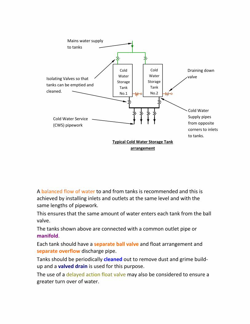
A balanced flow of water to and from tanks is recommended and this is achieved by installing inlets and outlets at the same level and with the same lengths of pipework.
This ensures that the same amount of water enters each tank from the ball valve.
The tanks shown above are connected with a common outlet pipe or manifold.
Each tank should have a separate ball valve and float arrangement and separate overflow discharge pipe.
Tanks should be periodically cleaned out to remove dust and grime build-up and a valved drain is used for this purpose.
The use of a delayed action float valve may also be considered to ensure a greater turn over of water.
Mains water supply
to tanks
Cold
Water
Storage
Tank
No.1
Cold
Water
Storage
Tank
No.2
Cold Water
Supply pipes
from opposite
corners to inlets
to tanks.
Isolating Valves so that
tanks can be emptied and
cleaned.
Draining down
valve
Typical Cold Water Storage Tank
arrangement
Cold Water Service
(CWS) pipework
The Water Supply (Water Quality) Regulations permit cold water to be delivered at temperatures up to 25°C, although in normal circumstances it will be well below 18°C but the aim should be to keep the temperature below 20°C as far as is practicable to restrict microbiological growth.
This is achieved by insulating all tanks, pipework, fittings and valves.
Tanks and pipework are also insulated to reduce condensation.
Also all pipework should be located away from warm areas such as plant rooms and warm roof spaces.
Pipework should not be routed through hot ducts or adjacent to heat sources, such as radiators and boilers.
Calculating Cold Water Storage Requirements
CIBSE Guide G (2004) Public Health Engineering gives data for calculating cold water storage requirements for various buildings.
Table 2.2 gives 24 hour storage requirements based on various fittings, e.g. Shower 140-230 litres, Bath 900 litres, WC 180 litres, Basin 90 litres, Sink 90-180 litres, Urinal 110 litres.
Where water storage is to be located in each domestic dwelling, this should be provided by a cold water storage cistern mounted in the roof space or similar area with a storage to water line of at least 227-300 litres.
The cistern should be protected from frost and designed to maintain the water quality.
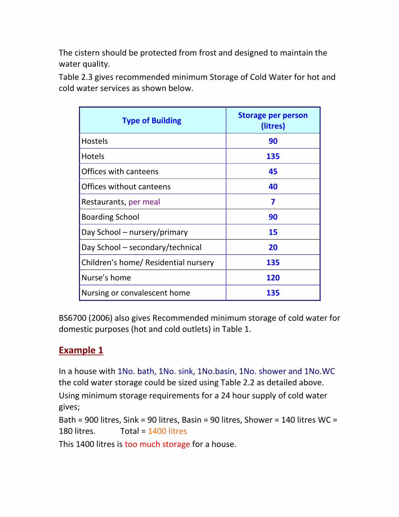
Table 2.3 gives recommended minimum Storage of Cold Water for hot and cold water services as shown below.
Type of Building Storage per person
(litres)
Hostels 90
Hotels 135
Offices with canteens 45
Offices without canteens 40
Restaurants, per meal 7
Boarding School 90
Day School – nursery/primary 15
Day School – secondary/technical 20
Children’s home/ Residential nursery 135
Nurse’s home 120
Nursing or convalescent home 135
BS6700 (2006) also gives Recommended minimum storage of cold water for domestic purposes (hot and cold outlets) in Table 1.
Example 1
In a house with 1No. bath, 1No. sink, 1No.basin, 1No. shower and 1No.WC the cold water storage could be sized using Table 2.2 as detailed above.
Using minimum storage requirements for a 24 hour supply of cold water gives;
Bath = 900 litres, Sink = 90 litres, Basin = 90 litres, Shower = 140 litres WC = 180 litres. Total = 1400 litres
This 1400 litres is too much storage for a house.

The older CIBSE B (1986) Table B4.2 gives storage at 90 litres per person in a house for 24 hours.
Storage Required = 90 x 5 people = 450 litres
From Institute of Plumbing Guide Table A11, the nearest tank size is SCM 680, which has an actual capacity of 491 litres to the water line, 680 litres is the nominal capacity of the tank.
The dimensions of this rectangular tank are 1092mm x 864mm x 736mm high.
Table A12 shows the equivalent tank as a circular Polythene or Polypropylene cistern.
The cistern in this case would be PC 100 with an actual capacity of 455 litres and a height of 760mm.
The statement in CIBSE Guide G (2004) section 2.4.3.1 gives domestic storage at 227-300 litres.
A typical circular storage tank is shown below.
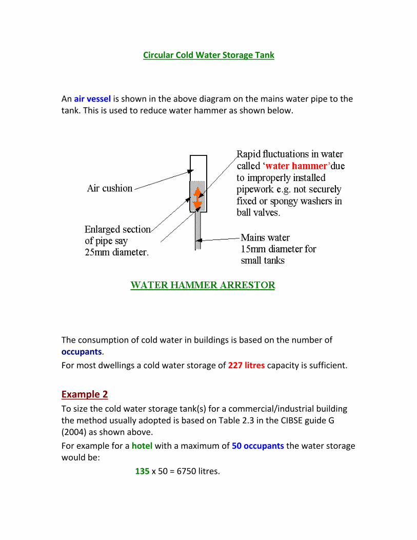
Circular Cold Water Storage Tank
An air vessel is shown in the above diagram on the mains water pipe to the tank. This is used to reduce water hammer as shown below.
The consumption of cold water in buildings is based on the number of occupants.
For most dwellings a cold water storage of 227 litres capacity is sufficient.
Example 2
To size the cold water storage tank(s) for a commercial/industrial building the method usually adopted is based on Table 2.3 in the CIBSE guide G (2004) as shown above.
For example for a hotel with a maximum of 50 occupants the water storage would be:
135 x 50 = 6750 litres.

The largest galvanised steel tank capacity in the Institute of Plumbing guide table A11 is 3364 litres.
Therefore: 2No. steel tanks of capacity each 3364 litres could be used giving a total water capacity of:
2 x 3364 = 6728 litres
Each tank dimensions are (A11) :
2438mm long x 1524mm wide x 1219mm high.
Note:
It is possible to have a non-storage system for cold water in a building although there would be no security of supply of cold water.
This means that there is no cold water storage tank in the building.
There would be no 24 hour storage capability so that if the water main was turned off, then WC’s could not flush and other sanitary items would be inoperable.
This is only possible in a small building where the mains water system is secure and is not turned off regularly and water is not required for important reasons.
A non-storage system is not recommended for commercial buildings but has been tried in some domestic systems.
There are some advantages in not storing water in a building, one is that there is no risk of frost damage and another is that there is less risk of water borne bacterial growth.
Hot Water Generation & Storage
Hot water is used for washing and cooking.
The temperature required is about 45oC.
Water is usually generated at a higher temperature (55oC to 65oC) in a vessel and mixed with cold water at mixing taps or mixing valves.

It is better to store water at a temperature much higher than body temperature (37oC) to reduce risk of bacteria growth and other water borne diseases.
Hot water service systems may be divided into two main types:
1. Local systems
2. Central systems
Local hot water systems can be further subdivided into instantaneous heaters and storage heaters:
· Instantaneous - Electric type with output of between 0.02 litre/s and 0.05 litre/s, electrical loading from 3kW to 10kW.
· Storage cylinders - for hot water - 7 to 70 litres capacity, with 3kW electrical heating elements.
Central systems usually consist of a boiler or hot water heater coupled by circulating piping to a large storage vessel.
The combination of the two will be so proportioned as to provide adequate service to the draw-off points, to match the predetermined pattern of usage.
For instance, in a hospital there may be a continuous demand for hot water all day and in this case a small storage capacity with a rapid recovery period (large boiler power) is probably appropriate.
Conversely, for a sports pavilion where there may be a single sudden demand following a game, a large storage capacity and a long recovery period (small boiler power) may be adequate.
Most central systems use indirect hot water cylinder(s) since direct systems can require frequent cleaning as scale deposits build up inside boilers.
When an indirect system is used the primary and secondary water systems have to be vented separately - primary water via. the feed and expansion (F & E) tank and secondary hot water via. the cold water storage cistern.
A typical DOMESTIC system is shown below.

Traditional or Un-Pressurised Hot and Cold Water
Plumbing System for a House
Water
Closet
Bath
Basin
Sink
Ground Floor
First Floor
Roofspace
Incoming Mains
Water Service
Stop valve under sink
in Kitchen or Utility
Room
Boiler
Primary flow and
return to HW
cylinder
Shower
head
Shower
mixing
valve
Hot Water
Service pipe
Indirect Hot Water
Cylinder suitable for
pressure operation
Open vent pipe
Open vent pipe
Feed & Expansion Tank
Cold Water Storage Tank
Cold water service
pipe
Cold feed pipe to Hot
water cylinder
Mains Water Service

The above diagram shows an indirect hot water cylinder, known as indirect because the hot water from the boiler (primary circulation) doesn't come into direct contact with the hot water in the cylinder (secondary circulation) - this water being used for washing and cooking.
The hot water cylinder, indirect coil and pipework are made of copper. It is feasible to use ‘plastic’ pipework for this and polybutylene is more frequently installed especially in concealed locations.
A vent is required on the hot water outlet pipe at the top of the cylinder to allow for water expansion and prevent the cylinder becoming pressurised when heated.
The temperature of water in the cylinder must be controlled in accordance with the building regulations. See CONTROLS section. This is achieved by an immersion thermostat in the cylinder or clamp-on thermostat either switching on and off a pump or control valve. An alternative method of control is to use a thermostatically controlled valve which has the sensing head on the cylinder.
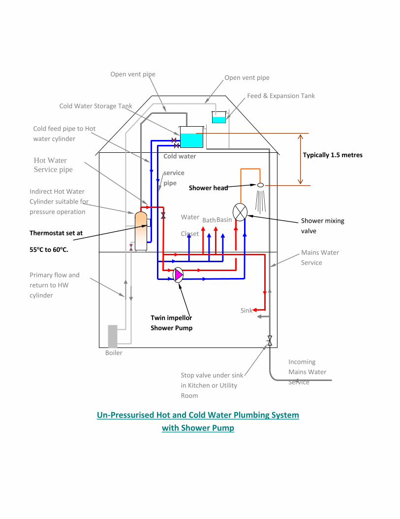
Un-Pressurised Hot and Cold Water Plumbing System
with Shower Pump
Sink
Incoming
Mains Water
Service
Stop valve under sink
in Kitchen or Utility
Room
Boiler
Primary flow and
return to HW
cylinder
Shower mixing
valve
Indirect Hot Water
Cylinder suitable for
pressure operation
Open vent pipe
Open vent pipe
Feed & Expansion Tank
Mains Water
Service
Typically 1.5 metres
Thermostat set at
55oC to 60oC.
Water
Closet
Bath
Basin
Shower head
Hot Water
Service pipe
Cold Water Storage Tank
Cold water
service
pipe
Cold feed pipe to Hot
water cylinder
Twin impellor
Shower Pump
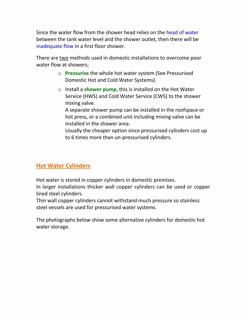
Since the water flow from the shower head relies on the head of water between the tank water level and the shower outlet, then there will be inadequate flow in a first floor shower.
There are two methods used in domestic installations to overcome poor water flow at showers;
o Pressurise the whole hot water system (See Pressurised Domestic Hot and Cold Water Systems).
o Install a shower pump, this is installed on the Hot Water Service (HWS) and Cold Water Service (CWS) to the shower mixing valve. A separate shower pump can be installed in the roofspace or hot press, or a combined unit including mixing valve can be installed in the shower area. Usually the cheaper option since pressurised cylinders cost up to 6 times more than un-pressurised cylinders.
Hot Water Cylinders Hot water is stored in copper cylinders in domestic premises. In larger installations thicker wall copper cylinders can be used or copper lined steel cylinders. Thin wall copper cylinders cannot withstand much pressure so stainless steel vessels are used for pressurised water systems.
The photographs below show some alternative cylinders for domestic hot water storage.
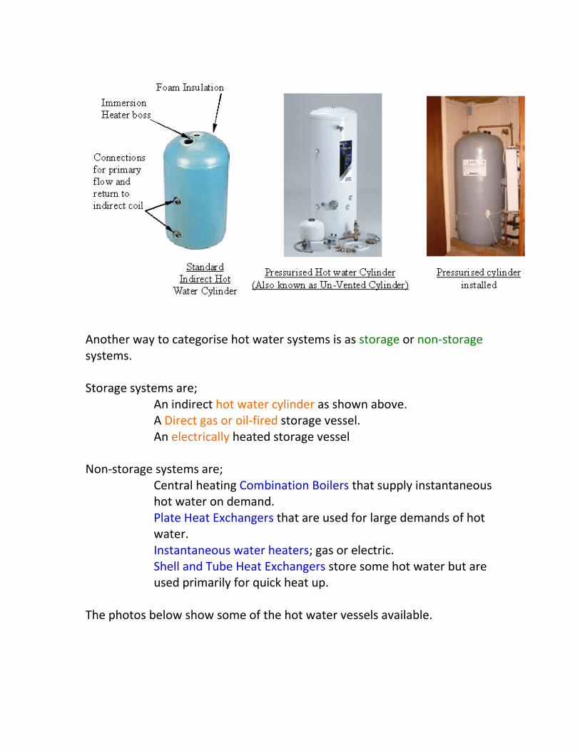
Another way to categorise hot water systems is as storage or non-storage systems. Storage systems are;
An indirect hot water cylinder as shown above. A Direct gas or oil-fired storage vessel. An electrically heated storage vessel
Non-storage systems are;
Central heating Combination Boilers that supply instantaneous hot water on demand.
Plate Heat Exchangers that are used for large demands of hot water.
Instantaneous water heaters; gas or electric. Shell and Tube Heat Exchangers store some hot water but are used primarily for quick heat up.
The photos below show some of the hot water vessels available.

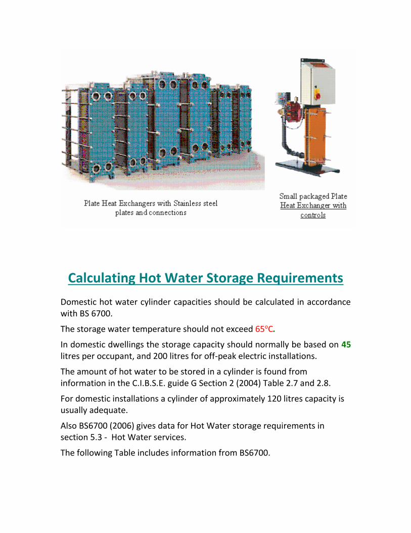
Calculating Hot Water Storage Requirements
Domestic hot water cylinder capacities should be calculated in accordance with BS 6700.
The storage water temperature should not exceed 65oC.
In domestic dwellings the storage capacity should normally be based on 45 litres per occupant, and 200 litres for off-peak electric installations.
The amount of hot water to be stored in a cylinder is found from information in the C.I.B.S.E. guide G Section 2 (2004) Table 2.7 and 2.8.
For domestic installations a cylinder of approximately 120 litres capacity is usually adequate.
Also BS6700 (2006) gives data for Hot Water storage requirements in section 5.3 - Hot Water services.
The following Table includes information from BS6700.

Domestic Appliances / Dwelling Hot Water requirement
Hot Water (60oC) used in dwellings 35 litres to 45 litres per person per day
Average bath
60 litres at 60oC plus
40 litres at 10oC plus
100 litres at 40oC plus
Shower 0.05 l/s to 0.15 l/s at 40 oC
Power shower Up to 0.20 l/s at 40oC to 60oC
Wash basin hot tap 0.10 l/s to 0.15 l/s at 40oC
Kitchen sink 0.10 l/s to 0.20 l/s at 60oC
Calculating Boiler Power Required to heat a Hot Water Cylinder
The amount of heat required from boiler plant is:
H = m x Cp x ( t hot - t cold ) / Hours heat up x Efficiency x 3600
Where; H = Heat required or Boiler Power (kW) m = Mass of water in cylinder (kg). 1kg of water = 1 litre Cp = Specific heat capacity of water (4.187 kJ/kg degC) t hot = Hot water temperature (about 60oC) t cold = Cold feed water temperature usually taken as 10oC Hours heat up = Allow 1.5 to 3 hours for a standard cylinder to heat up. Efficiency = usually taken as 0.9 since hot water cylinders are insulated. 3600 = To convert hours to seconds.
Example 1
Calculate the boiler power required to heat a 120 litre hot water cylinder in 1.5 hours.

The hot water temperature is 60oC and the cold feed temperature is 10oC.
H = m x Cp x ( t hot - t cold ) / Hours heat up x Efficiency x 3600
H = 120 kg x 4.187 x ( 60 - 10 ) / 1.5 x 0.9 x 3600
H = 5.17 kW
Example 2
Calculate the boiler power required to heat a 120 litre hot water cylinder in 1.5 hours. The hot water temperature is 55oC and the cold feed temperature is 10oC.
H = m x Cp x ( t hot - t cold ) / Hours heat up x Efficiency x 3600
H = 120 kg x 4.187 x ( 55 - 10 ) / 1.5 x 0.9 x 3600
H = 4.65 kW
Example 3
Calculate the boiler power required to heat a 500 litre hot water cylinder for a Nursing Home in 2.0 hours. The hot water temperature is 65oC and the cold feed temperature is 10oC.
H = m x Cp x ( t hot - t cold ) / Hours heat up x Efficiency x 3600
H = 500 kg x 4.187 x ( 65 - 10 ) / 2.0 x 0.9 x 3600
H = 17.77 kW

Other Calculations for a Hot Water Cylinder
Example 4
Calculate the annual energy required to heat a hot water cylinder installation in a household of three people. DATA The hot water temperature is 55oC and the cold feed temperature is 10oC. For a household of three people the daily DHW is 120 litre/ day. (see CIBSE Solar Heating Design and Installation Guide (2007) Section 7.5.4 – Calculating DHW loads) Annual heat loss from the pipework is 232 kWh / year. (see CIBSE Solar Heating Design and Installation Guide (2007) page 76) Annual heat loss from the insulated cylinder is 354 kWh / year. (see CIBSE Solar Heating Design and Installation Guide (2007) page 77) corrected for 120 litre cylinder. Annual heat loss from the cylinder fittings is 50 kWh / year. (see CIBSE Solar Heating Design and Installation Guide (2007) page 77) Annual store heat loss factor is 0.0152 kWh / litre /day. Insulation thickness is 50mm (see CIBSE Solar Heating Design and Installation Guide (2007) page 78) Annual store heat loss = 0.0152 x 120 x 365 = 666 kWh / year
Daily Energy requirement E = m x Cp x ( t hot - t cold ) / Efficiency
E = 120 kg x 4.187 x ( 55 - 10 ) / 0.9
E = 25,122 kJ
E = 25.12 MJ 1 kWh = 1 kJ/s x 3600 s = 3600 kJ = 3.6 MJ E = 25.12 / 3.6 = 6.98 kWh
Annual Energy requirement = E x 365 days / year Annual Energy requirement = 6.98 x 365 = 2547 kWh / year.
Add other energy losses.
Total annual energy requirement = 2547 + 232 + 354 + 50 + 666 = 3849 kWh/ year.
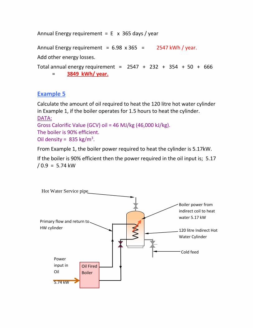
Example 5
Calculate the amount of oil required to heat the 120 litre hot water cylinder in Example 1, if the boiler operates for 1.5 hours to heat the cylinder. DATA: Gross Calorific Value (GCV) oil = 46 MJ/kg (46,000 kJ/kg). The boiler is 90% efficient. Oil density = 835 kg/m3.
From Example 1, the boiler power required to heat the cylinder is 5.17kW.
If the boiler is 90% efficient then the power required in the oil input is; 5.17 / 0.9 = 5.74 kW
Hot Water Service pipe
120 litre Indirect Hot
Water Cylinder
Primary flow and return to
HW cylinder
Cold feed
Power
input in
Oil
5.74 kW
Oil Fired
Boiler
Boiler power from
indirect coil to heat
water 5.17 kW
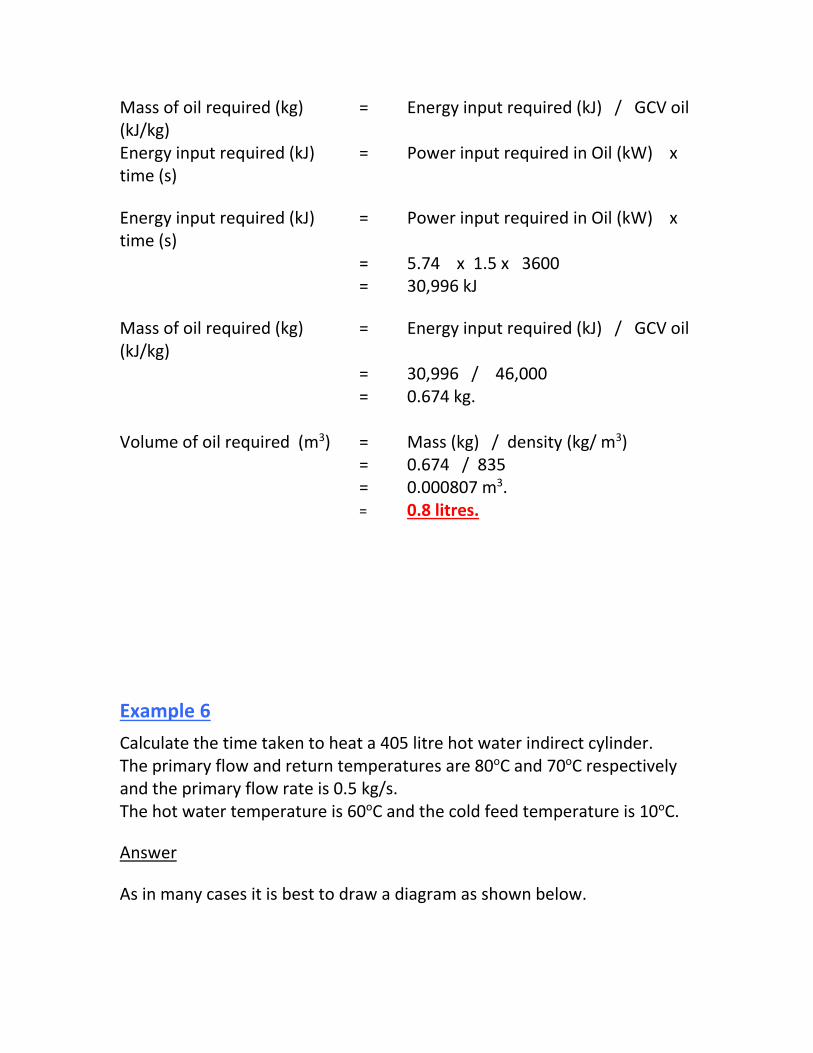
Mass of oil required (kg) = Energy input required (kJ) / GCV oil (kJ/kg) Energy input required (kJ) = Power input required in Oil (kW) x time (s)
Energy input required (kJ) = Power input required in Oil (kW) x time (s) = 5.74 x 1.5 x 3600 = 30,996 kJ
Mass of oil required (kg) = Energy input required (kJ) / GCV oil (kJ/kg) = 30,996 / 46,000 = 0.674 kg. Volume of oil required (m3) = Mass (kg) / density (kg/ m3) = 0.674 / 835 = 0.000807 m3. = 0.8 litres.
Example 6
Calculate the time taken to heat a 405 litre hot water indirect cylinder. The primary flow and return temperatures are 80oC and 70oC respectively and the primary flow rate is 0.5 kg/s. The hot water temperature is 60oC and the cold feed temperature is 10oC.
Answer
As in many cases it is best to draw a diagram as shown below.

The heat input by the primary water from the boiler is; H = m flow x Cp x (t flow - t return) Where; H = Heat input from boiler to primary flow and return water (kW) m flow = Primary water mass flow rate (kg/s) t flow = Primary flow water temperature (oC) t return = Primary return water temperature (oC)
H = 0.5 x 4.187 x ( 80 - 70 ) H = 20.94 kW.
= m x Cp x ( t hot - t cold ) / Hours heat up x Efficiency x 3600
Rearranging the above formula gives;
Hours heat up =m x Cp x ( t hot - t cold ) / H x Efficiency x 3600
Hours heat up =405 x 4.187 x ( 60 - 10 ) / 20.94 x 0.9 x 3600
Hours heat up = 1.25 hours
Hot Water Service pipe
60oC 405 litre Indirect Hot
Water Cylinder
Primary flow and return to
HW cylinder, 0.5 kg/s
Cold feed 10oC
Boiler
80oC
70oC

Pressurised Domestic Hot & Cold Systems To provide adequate pressure of hot and cold water at sanitary appliances
(particularly showers) an unvented system is used.
Pressurised Hot System
For pressurised hot water supply this can be provided by a Combination
boiler (see Heating section) or by a pressurised cylinder as shown below.
This is sometimes called an unvented hot water system.
Pressure
Reducing Valve
(PRV)
Pressurised or Unvented Hot and Cold Water Plumbing
System for a House
Water
Closet
Bath
Basin
Sink
Ground
Floor
First Floor
Roofspace
Incoming Mains
Water Service
Stop valve under
sink in Kitchen or
Utility Room
Cold Feed pipe to
hot water cylinder
Boiler
Primary flow and
return to HW
cylinder
Air Vent
Shower
head
Shower
mixing
valve
Air Vent
Hot Water
Service pipe
Indirect Hot Water
Cylinder suitable
for pressure
operation
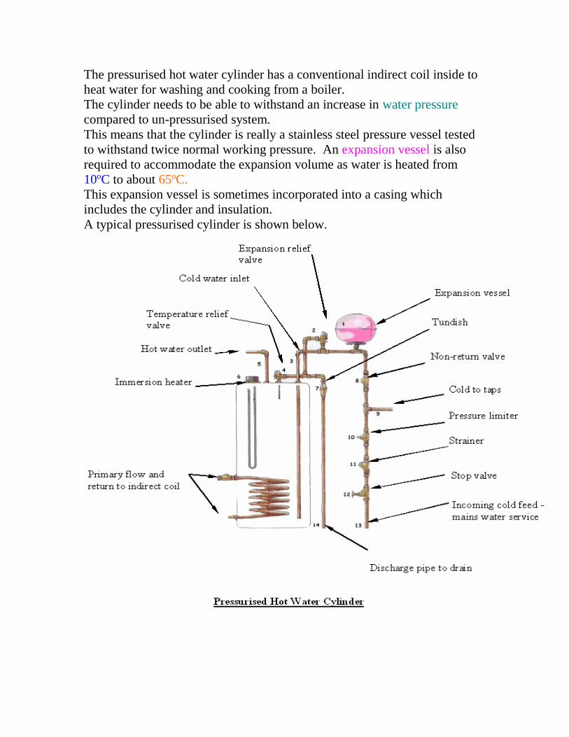
The pressurised hot water cylinder has a conventional indirect coil inside to
heat water for washing and cooking from a boiler.
The cylinder needs to be able to withstand an increase in water pressure
compared to un-pressurised system.
This means that the cylinder is really a stainless steel pressure vessel tested
to withstand twice normal working pressure. An expansion vessel is also
required to accommodate the expansion volume as water is heated from
10oC to about 65oC.
This expansion vessel is sometimes incorporated into a casing which
includes the cylinder and insulation.
A typical pressurised cylinder is shown below.
Pressurised Cold System
There is no difficulty providing pressurised cold water in a house since the
mains system can be used and piped via. a pressure reducing valve (PRV) to
sink, bath, basin, shower and w.c.
This is shown above in the diagram; Pressurised or Unvented Hot & Cold
Water Plumbing System for a House.
The Pressure Reducing Valve (PRV) is essential to reduce the pressure
from about 3 bar to 1.5 bar.
This is sufficient pressure to operate domestic sanitary appliances, if the
pressure is too high there is more chance of leaks, more water is used and
water may spray back from basins.
Isolation
It is always good practice to install isolating valves at each sanitary
appliance for both hot and cold services.
This means that local maintenance can be carried out easily.
Inexpensive quarter turn ball valves can be used.
Cold Water to High Rise Buildings
If the head of water in the main is not sufficient to supply water to the top floors of high rise buildings, then it will probably be necessary to pump water to the top of the building. The head of water which is available in the mains can easily be calculated by using the following formula:
p = x g x h
Rearranging gives; h = p / ( x g )
Where; p = Water pressure (N/m2 or Pa) To convert from bar pressure – 1 bar = 100,000
N/m2 or Pa.
= Density of water (1000 kg/m3) g = Acceleration due to gravity ( 9.81 m/s2) h = Head (m)

Example 1
For a water pressure of 3.4 bar the equivalent head would be;
h = p / ( x g ) h = 3.4 x 100,000 / ( 1000 x 9.8 ) h = 34.66 metres This means that the water main is capable of delivering water to a height of 34.66 metres. There would be no flow of water from a pipe at this height and we have not taken pipe and fitting resistance into account.
To overcome these difficulties a water pressure boosted system is necessary.
For an approximate conversion from bar pressure to head multiply by 10.
Example 2
Calculate approximately the head of water in a reservoir if the pressure is 4 bar.
Answer: 4 bar x 10 = 40 metres head approximately.
This can be compared to the accurate answer which is; 40.775 metres.
Pressure Boosting
Pressure boosting equipment can be divided into three categories:
1. The pneumatic system, as shown on the following page is essentially pressure controlled.
2. The intermittent pump system which is essentially float switch controlled.
3. The continuously running pump system which is a useful application for smaller systems and relies for its control upon

careful choice of pump characteristic and a small pressure bleed from delivery to suction.
See below details of these systems.
Cold Water to High Rise Buildings
Pneumatic Boosting
A typical pneumatic cold water boosting system is shown below.
PNEUMATIC BOOSTING FOR COLD WATER SYSTEM

In the pneumatic boosting system a cushion of air under pressure is maintained in the top of a pressure vessel. When a tap is opened the air is able to expand by forcing the water out of the cylinder and through the pipework. This process can continue until the water level drops to a predetermined point, when the pumps will be switched on to raise the level again.
Drinking water is drawn off from the pressure vessel, although the drinking water can be supplied direct to lower floors where the mains pressure is sufficient.
In the boosted water system, precautions are taken to ensure purity of water. The air pumped in, is filtered to prevent dust and insects gaining access, and the capacity of the vessel is kept reasonably small to prevent stagnation - viral diseases can spread when bacteria are allowed to multiply in humid, stagnant and warm conditions.
For dwellings, the volume of water between high and low levels would typically be no more than 4.5 litres per dwelling. For flats of about 15 floors a simplified system is possible as shown below. The system below differs from the previous design, principally in that minor drinking water is supplied by means of an enlarged section of pipe above the
level of the highest flat.
This enlarged section allows water to flow to drinking water taps without the
pump being operated until the section becomes empty.

SYSTEM FOR RAISING WATER TO FLATS
For buildings higher than about 10 storeys it is necessary that consideration be given to pressure balancing at individual draw-off fittings by means of orifice plates or by arranging the piping system in vertical zones with reducing valves. For very high buildings, the provision of intermediate water storage and further pumping equipment may be necessary. The drawing below shows a typical boosted cold water system for a high rise building such as a block of flats or apartments.
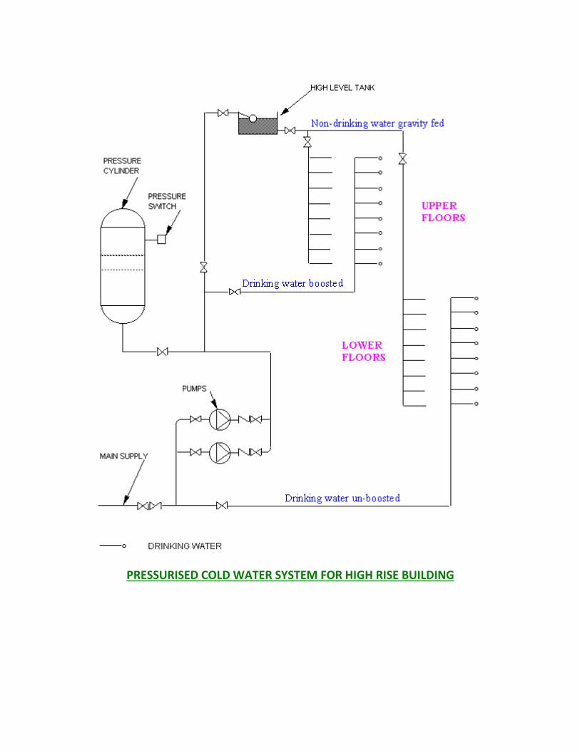
PRESSURISED COLD WATER SYSTEM FOR HIGH RISE BUILDING

Fire Protection Piped Systems
Water is commonly used to extinguish and curtail fires in buildings.
Some of the water based systems used are;
Fire Extinguishers
Sprinklers
Risers
Hose reels
Hydrants
Foam systems
Fire Extinguishers
There are four different types or classes of fire extinguishers, each of which
extinguishes specific types of fire.
Fire extinguishers use a picture/labelling system to designate which types of
fires they are to be used on. Most fire extinguishers are labelled with
coloured geometrical shapes with letter designations. Fire extinguishers are
labelled according to the type of fire on which they may be used. Fires
involving wood or cloth, flammable liquids, electrical, or metal sources react
differently to extinguishers.
Traditionally, the labels A,B, C or D have been used to indicate the type of
fire on which an extinguisher is to be used.
Class A Extinguishers are labelled in a triangle on the extinguisher. This
extinguisher is used for ordinary combustibles such as cloth, wood, rubber
and many plastics. These types of fire usually leave ashes after they burn.
Type A extinguishers for Ashes.
Class B Extinguishers are labelled in a square on the extinguisher. This
extinguisher is used for flammable liquid fires such as oil, gasoline, paints,
lacquers, grease, and solvents. These substances often come in barrels. Type
B extinguishers for Barrels.
Class C Extinguishers are labelled in a circle on the extinguisher. This
extinguisher is used for electrical fires such as in wiring, fuse boxes,
energized electrical equipment and other electrical sources. Electricity
travels in currents. Type C extinguishers for Currents.
Class D Extinguishers are labelled in a star on the extinguisher. This
extinguisher is used for metal fires such as magnesium, titanium and sodium.
These types of fire are very dangerous and seldom handled by the general
public. Type D for Don't get involved.
Dry Powder extinguishers are usually rated for multiple purpose use. They
contain an extinguishing agent and use a compressed, non-flammable gas as
a propellant.
Foam extinguishers have a smothering affect, depriving fire of oxygen.
These type of fire extinguishers are especially effective on Class B
(flammable liquid) fires, it can also be used on Class A (carbonaceous) fires,
paper and wood.
Water These extinguishers contain water and compressed gas and should
only be used on Class A (ordinary combustibles) fires.
Carbon Dioxide (CO2) extinguishers are most effective on Class B and C
(liquids and electrical) fires. Since the gas disperses quickly, these
extinguishers are only effective from 3 to 8 feet. The carbon dioxide is
stored as a compressed liquid in the extinguisher; as it expands, it cools the
surrounding air. The cooling will often cause ice to form around the “horn”
where the gas is expelled from the extinguisher. Since the fire could re-
ignite, continue to apply the agent even after the fire appears to be out.
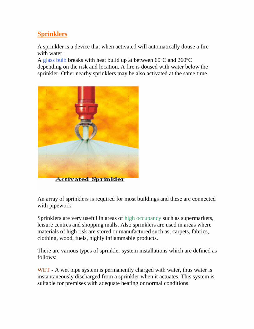
Sprinklers
A sprinkler is a device that when activated will automatically douse a fire
with water.
A glass bulb breaks with heat build up at between 60oC and 260oC
depending on the risk and location. A fire is doused with water below the
sprinkler. Other nearby sprinklers may be also activated at the same time.
An array of sprinklers is required for most buildings and these are connected
with pipework.
Sprinklers are very useful in areas of high occupancy such as supermarkets,
leisure centres and shopping malls. Also sprinklers are used in areas where
materials of high risk are stored or manufactured such as; carpets, fabrics,
clothing, wood, fuels, highly inflammable products.
There are various types of sprinkler system installations which are defined as
follows:
WET - A wet pipe system is permanently charged with water, thus water is
instantaneously discharged from a sprinkler when it actuates. This system is
suitable for premises with adequate heating or normal conditions.

DRY - A dry pipe system is suitable for premises where low temperatures
could cause a wet pipe system to freeze e.g. Cold Stores. Dry pipe systems
are charged with compressed air. When the sprinkler head actuates, the air is
released so that water can flow through the pipework and reach the fire.
ALTERNATE - An alternate pipe system is charged with compressed air
during the winter and water for the remainder.
TAIL END - A tail end pipe system is where a small section of a Wet
System is kept 'dry' during the winter e.g. a canopy.
PRE-ACTION - An electrical fire detection system is fitted in conjunction
with a dry pipe system, which is water filled in advance of sprinkler
operation e.g. a computer suite.
Wet pipe systems are the most common sprinkler system.
Wet pipe system advantages include:
System simplicity and reliability. Wet pipe sprinkler systems have
the least number of components and therefore, the lowest number of
items to malfunction. This produces unexcelled reliability which is
important since sprinklers may be asked to sit in waiting for many
years before they are needed. This simplicity aspect also becomes

important in facilities where system maintenance may not be
performed with the desired frequency.
Relative low installation and maintenance expense. Due to their
overall simplicity, wet pipe sprinklers require the least amount of
installation time and capital. Maintenance cost savings are also
realized since less service time is generally required, compared to
other system types. These savings become important when
maintenance budgets are shrinking.
Ease of modification. Heritage institutions are often dynamic with
respect to exhibition and operation spaces. Wet pipe systems are
advantageous since modifications involve shutting down the water
supply, draining pipes and making alterations. Following the work,
the system is pressure tested and restored. Additional work for
detection and special control equipment is avoided which again saves
time and expense.
Short term down time following a fire. Wet pipe sprinkler systems
require the least amount of effort to restore. In most instances,
sprinkler protection is reinstated by replacing the fused sprinklers and
turning the water supply back on. Preaction and dry-pipe systems may
require additional effort to reset control equipment.
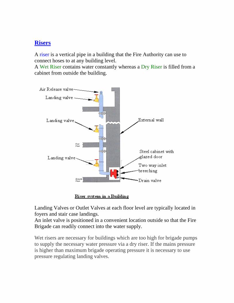
Risers
A riser is a vertical pipe in a building that the Fire Authority can use to
connect hoses to at any building level.
A Wet Riser contains water constantly whereas a Dry Riser is filled from a
cabinet from outside the building.
Landing Valves or Outlet Valves at each floor level are typically located in
foyers and stair case landings.
An inlet valve is positioned in a convenient location outside so that the Fire
Brigade can readily connect into the water supply.
Wet risers are necessary for buildings which are too high for brigade pumps
to supply the necessary water pressure via a dry riser. If the mains pressure
is higher than maximum brigade operating pressure it is necessary to use
pressure regulating landing valves.
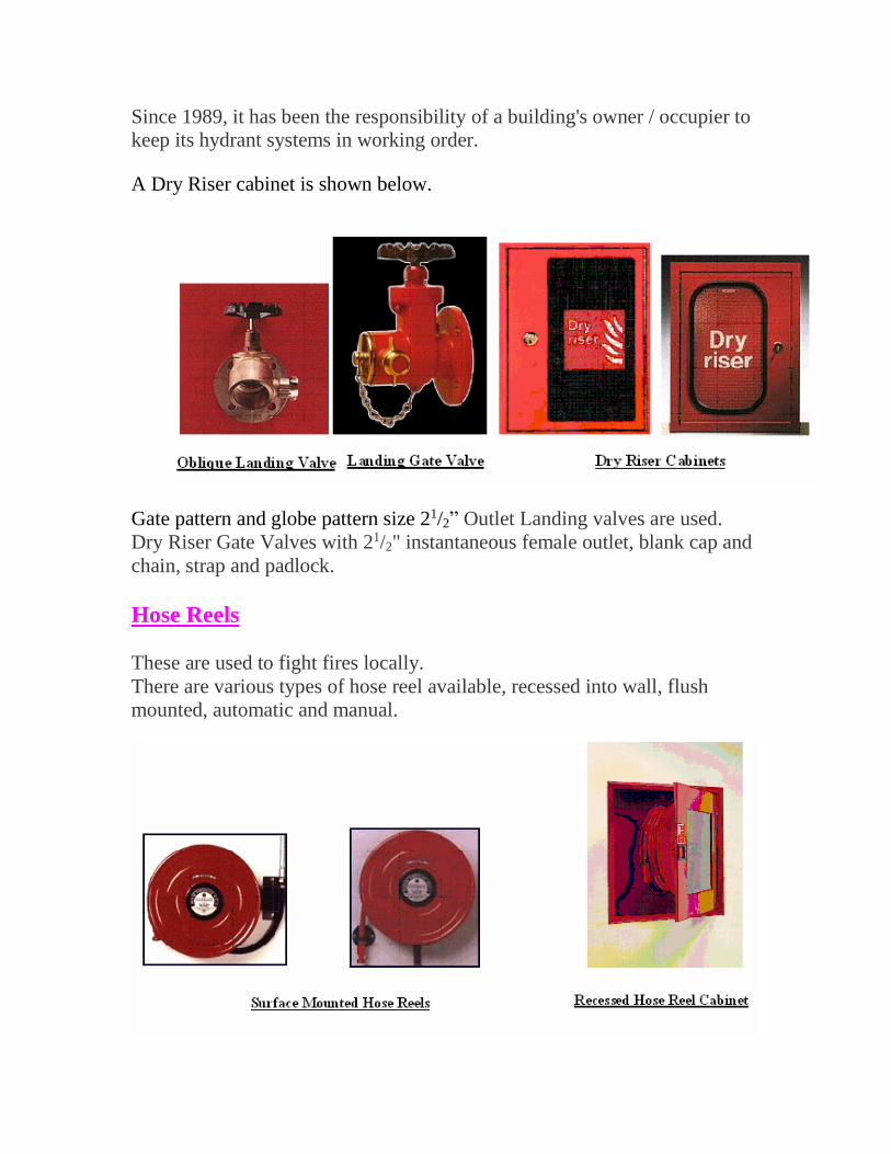
Since 1989, it has been the responsibility of a building's owner / occupier to
keep its hydrant systems in working order.
A Dry Riser cabinet is shown below.
Gate pattern and globe pattern size 21/2” Outlet Landing valves are used.
Dry Riser Gate Valves with 21/2" instantaneous female outlet, blank cap and
chain, strap and padlock.
Hose Reels
These are used to fight fires locally.
There are various types of hose reel available, recessed into wall, flush
mounted, automatic and manual.

Hydrants
Fire hydrants are used to supply a large flow of water to fight fires.
They are positioned in public roads and within large building complexes.
The fire brigade uses the hydrant as a quick and easy method of obtaining
water from the mains water system, instead of having to rely solely on water
tanks in tenders.
Foam Systems
These are used to protect vulnerable plant and equipment in the event of a
fire. A foam spreader allows foam to be pumped into the area through
pipework and a foam entry box. This is used in fuel storage areas where the
location of the oil or gas tank may cause danger in the event of a fire.
The fire brigade carry foam making equipment on tenders so that they can
connect to the inlet box in a convenient location.
Other systems employ special foam making apparatus that can be
transported to a fire.
Recycled Water Recycled water may come from two sources; rainwater and greywater.
Greywater is the wastewater from sinks, baths, showers and domestic
appliances. A greywater use system captures this water before it reaches
the sewer (or septic tank system). Kitchen sink or dishwasher wastewater is
not generally collected for use as it has high levels of contamination from
detergents, fats and food waste, making filtering and treatment difficult and
costly. Rainwater can be diverted from the roof drainage system to be used
in other appliances. Greywater systems can be more costly than rainwater
recycled systems since the water needs to be well filtered and treated to
make it usable. The cheaper option in areas of moderate to high rainfall
throughout the year is to recycle rainwater.
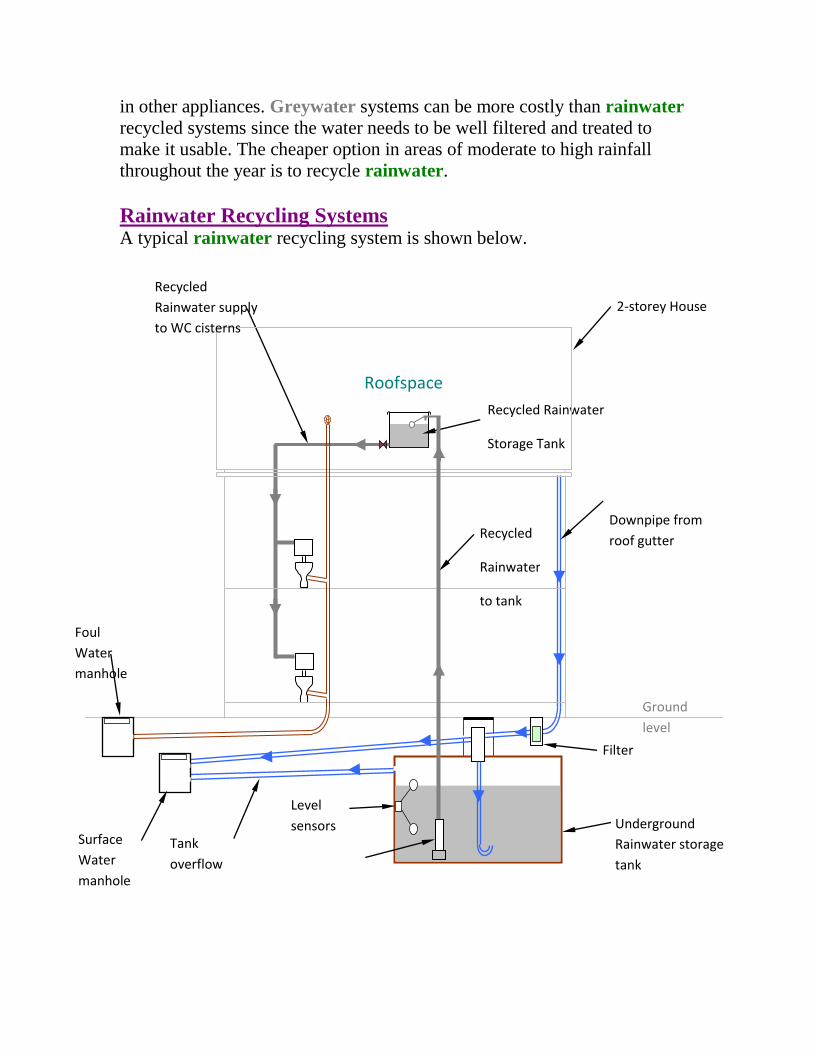
Rainwater Recycling Systems A typical rainwater recycling system is shown below.
Roofspace
Filter
Recycled Rainwater
Storage Tank
Recycled
Rainwater
to tank
Underground
Rainwater storage
tank
Recycled
Rainwater supply
to WC cisterns
2-storey House
Ground
level
Level
sensors
Downpipe from
roof gutter
Foul
Water
manhole
Surface
Water
manhole
Tank
overflow

Introduction to Drainage
Drainage schemes for buildings are necessary to remove waste water, foul
water and surface water.
Waste water and foul water join together and are disposed in a septic tank
in rural areas or to a foul water sewer in urban areas.
The foul water sewer discharges the sewerage to a treatment plant where it is
settled, filtered and chemically treated.
Surface water can be discharged into a soakaway, to a river or lake in rural
areas or to the surface water (or Storm Water) drain in urban areas. The
storm water drain discharges water safely to a river or lake.
A separate system of drainage is used where foul water and surface water
are separated at source and piped individually to a surface water drain or
foul water drain.
The diagram below shows a typical arrangement for a small rural dwelling.

Outlet from septic tank to
soakaway – perforated drain
into percolating sub-soil

The diagram below shows a typical arrangement for a small urban dwelling.

Drainage inside Dwellings
The system of drainage inside dwellings is installed to that access can be
obtained for possible cleaning.
This access is usually at basin and sink water seal traps and at access bends,
branches where used.
The drawing below shows inside drainage in the single storey dwelling
shown above.
100mm diameter
foul water drains
through floor and
underground to
outside
W.C.
Sink
Bath
Basin
40mm waste from sink trap
connects to 100mm foul water
drain at floor level.
40mm waste from bath trap
connects to 100mm foul water
drain at floor level.
32mm waste from basin
trap connects to 100mm
foul water drain at floor
level.
100mm soil outlet from W.C. trap connects
to 100mm foul water drain at floor level.
100mm
underground foul
water drains
Soils and Wastes drainage in Single Storey Dwelling