main bearing - rskr.irimee.in
TRANSCRIPT

MAIN BEARING

DIESEL ENGINE BEARING

Bearing Terminology

A thinwall bearing is a prefinished precision made steel backed
component lined with an appropriate bearing material that should be
capable of withstanding the applied load and be compatible with the
crankshaft.

Thinwall bearings offer the engine designer a range of materials and allow
good repeatability of a bearing assembly. In a bolted up assembly,
bearings will conform to the profile of the housing bore and therefore any irregularities in that housing will be
reflected in the bearing.


Bearing Lining

A bearing is made up of various layers of materials .The lining is bonded to the steel backing. In some cases via a thin bonding layer of aluminium or copper
based material.
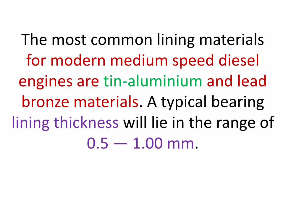
The most common lining materials for modern medium speed diesel
engines are tin-aluminium and lead bronze materials. A typical bearing
lining thickness will lie in the range of 0.5 — 1.00 mm.
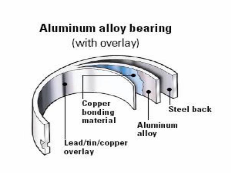


Overlay
On the majority of medium speed diesel engine bearings, a thin soft overlay plate
is applied to the lining material. The overlay provides better conformability and embeddability characteristics and
consequently improves the wear rate and the bearing life.
Crankshaft wear is also reduced, particularly when the harder bearing
materials are used. The most common overlays are lead-tin and lead-tin-copper.
On corrosion prone copper lead lined bearings, an intact overlay will also
provide some protection against corrosion by degraded or contaminated
oils.

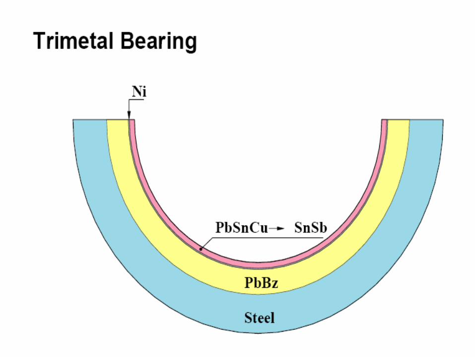
Interlayer
On certain bearings a thin interlayer, typically nickel of no more than 5
m, is applied between the bearing lining and overlay plate. On tin-aluminium bearings the nickel is
required to ensure satisfactory bond of the overlay.

On lead bronze bearings the nickel interlayer generally reduces the
rate of tin diffusion and wear rate and increases the corrosion
resistance of the overlay.

Flash
On the majority of bearings a thin "flash" of either tin or lead tin will be applied to the bearing bore and back. This flash provides protection against corrosion prior to the installation of
the bearing. A typical thickness of flash would be of the order of 1-2 m.

Bearing Assembly Check List
This check list itemises the most
important aspects that should be
covered prior to and during
assembly of crankshaft bearings.
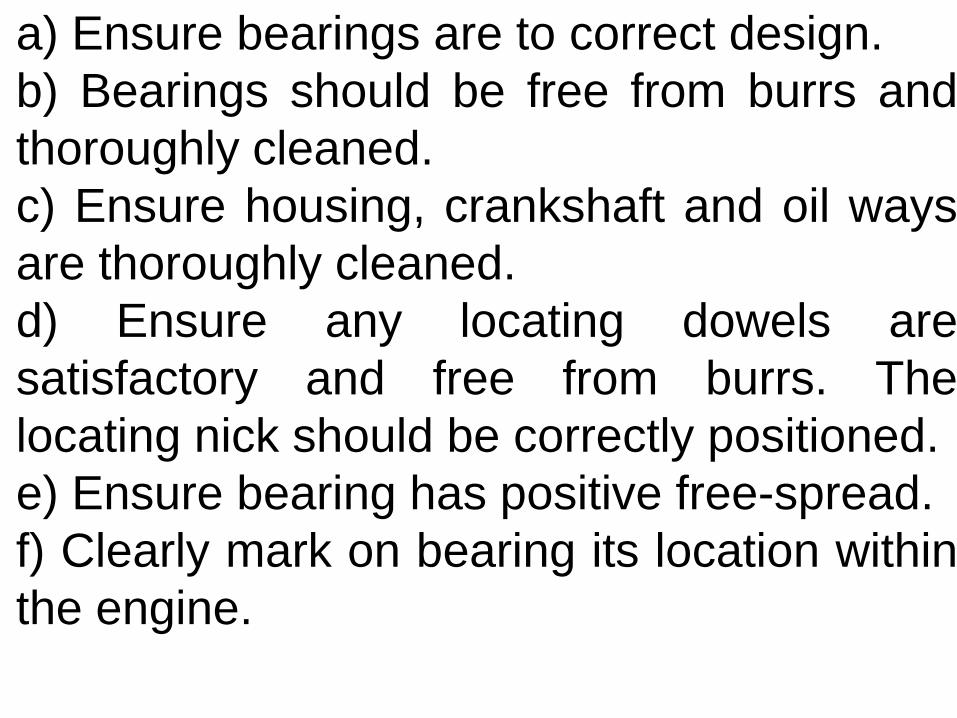
a) Ensure bearings are to correct design.
b) Bearings should be free from burrs and
thoroughly cleaned.
c) Ensure housing, crankshaft and oil ways
are thoroughly cleaned.
d) Ensure any locating dowels are
satisfactory and free from burrs. The
locating nick should be correctly positioned.
e) Ensure bearing has positive free-spread.
f) Clearly mark on bearing its location within
the engine.
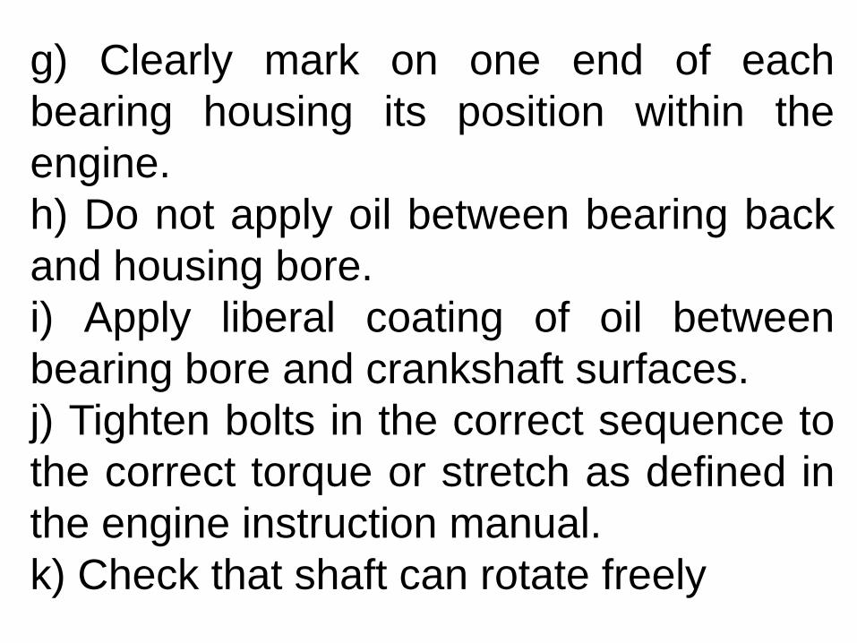
g) Clearly mark on one end of each
bearing housing its position within the
engine.
h) Do not apply oil between bearing back
and housing bore.
i) Apply liberal coating of oil between
bearing bore and crankshaft surfaces.
j) Tighten bolts in the correct sequence to
the correct torque or stretch as defined in
the engine instruction manual.
k) Check that shaft can rotate freely

Bearing properties

Good fatigue strength due to the both fine micro-structure and hardening effect of silicon and copper;
• Very good seizure resistance particularly with cast iron crankshafts.

This isprovided by silicon particles. They continuously polish the
crankshaft surface andprevent seizure.
•
Good embedability.
The lining is thick so it is capable to absorb both small and large dirt particles circulating with the oil;


• Good conformability. In contrast to tri-metal bearings with thin overlays, bimetal materials are capable of accommodating greater misalignments;• Good wear resistance due to the relatively hard aluminum alloy, which is harder than the soft overlays of tri-metal bearings.

TYPES OF BIMETAL & TRI METAL BEARING DEFECTS
1. FATIGUE FAILURES
2 CHEMICAL CORROSION
3 WATER EFFECT
4 CAVITATION AND ERROSION
5 MECHANICAL WEAR AND SCORING
6 WIPING AND SIZURE
7 BOND FAILURE
8 SPLIT LINE FRETTING
9 STATIC FRETTING
10 BACK FRETTING AND CREEP
11 MISC DEFECT
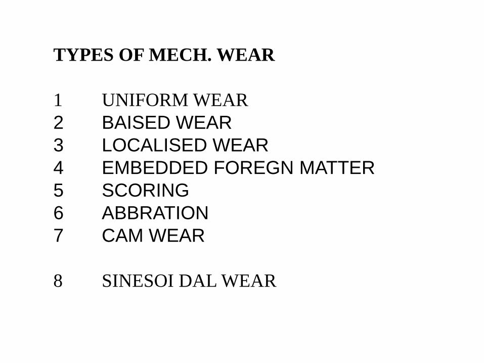
TYPES OF MECH. WEAR
1 UNIFORM WEAR
2 BAISED WEAR
3 LOCALISED WEAR
4 EMBEDDED FOREGN MATTER
5 SCORING
6 ABBRATION
7 CAM WEAR
8 SINESOI DAL WEAR

To assist an investigation of bearing damage, the
following check list itemises particular points that
should be established.
a) Duration of operation of bearing.
b) Engine designation and application.
c) History of engine operation.
d) Have bearings from same engine previously
shown similar damage, particularly in the same
assembly?
e) Has bearing been examined during service
and if so what was the condition of the bearing at
that time?

f)What is the condition of the other bearings within the
engine?
g) Have any other engine components suffered
damage, eg piston?
h) What is the condition of the crankshaft?
i) What is the condition of the bearing housing?
j) Is there a defect within the engine, eg faulty oil
pump, blocked filter, water leak?
k) Have there been any changes to the bearing
installation procedure?
Bearing Damage Associated with Assembly