mai muun mua on uimitat a la miti...mai muun mua on uimitat a la miti us009769902b1 ( 12 ) united...
TRANSCRIPT

MAI MUUN MUA ON UIMITAT A LA MITI US009769902B1
( 12 ) United States Patent Cain et al .
( 10 ) Patent No . : US 9 , 769 , 902 B1 ( 45 ) Date of Patent : Sep . 19 , 2017
( 54 ) LASER SENSOR STIMULATOR ( 56 ) References Cited U . S . PATENT DOCUMENTS @ ( 75 ) Inventors : Anthony M . Cain , Beavercreek , OH
( US ) ; Danny J . Hugh , Fairborn , OH ( US ) ; Donald R . Thomas , Beavercreek , OH ( US ) ; Shawn R . Davidson , Xenia , OH ( US )
@ . . . . . . . . . . . . . ( 73 ) Assignee : The United States of America as represented by Secretary of the Air Force , Washington , DC ( US ) . . . . . . . . . . .
@ ( * ) Notice :
3 , 392 , 260 A * 7 / 1968 Dernbach . . . . . . . . . . . . . . . 219 / 121 . 11 3 , 627 , 429 A * 12 / 1971 Jaenicke et al . . . . . . . . . . . . . . 356 / 153 4 , 050 , 068 A 9 / 1977 Berg et al . 4 , 146 , 780 A 3 / 1979 Sprey 4 , 205 , 902 A 6 / 1980 Shafer 4 , 273 , 536 A 6 / 1981 Wick 4 , 276 , 520 A * 6 / 1981 Rosenberg . . . . . . 372 / 34 4 , 647 , 759 A 3 / 1987 Worsham et al . 5 , 036 , 517 A * 7 / 1991 Meyers . . . . 372 / 38 . 04 5 , 072 , 342 A * 12 / 1991 Minovitch . 362 / 111 5 , 198 , 607 A 3 / 1993 Livingston et al . 5 , 216 , 236 A 6 / 1993 Blais 5 , 532 , 880 A 7 / 1996 Robb 5 , 612 , 503 A 3 / 1997 Sepp 5 , 676 , 450 A * 10 / 1997 Sink et al . . . . . . . . . . . . . . . . 362 / 112 5 , 685 , 636 A * 11 / 1997 German 362 / 259 5 , 711 , 102 A * 1 / 1998 Plaster et al . . . . . . . . . . . . . 42 / 71 . 01 5 , 739 , 787 A 4 / 1998 Burke et al . 5 , 747 , 720 A 5 / 1998 Schnurr et al . 5 , 864 , 481 A 1 / 1999 Gross et al .
( Continued )
Subject to any disclaimer , the term of this patent is extended or adjusted under 35 U . S . C . 154 ( b ) by 1659 days .
( 21 ) Appl . No . : 13 / 103 , 440
( 22 ) Filed : May 9 , 2011
OTHER PUBLICATIONS
( 51 ) Int . Ci . GOIC 3 / 08 ( 2006 . 01 ) H05B 37 / 00 ( 2006 . 01 ) F41G 1 / 00 ( 2006 . 01 ) F21V 21 / 00 ( 2006 . 01 ) F21V 33 / 00 ( 2006 . 01 ) GOIB 21 / 00 ( 2006 . 01 ) F416 1 / 32 ( 2006 . 01 )
( 52 ) U . S . CI . ??? . . . H05B 37 / 00 ( 2013 . 01 ) ; F21V 21 / 00
( 2013 . 01 ) ; F21V 33 / 00 ( 2013 . 01 ) ; F416 1 / 00 ( 2013 . 01 ) ; F41G 1 / 32 ( 2013 . 01 ) ; GOIB 21 / 00
( 2013 . 01 ) ; G01C 3 / 08 ( 2013 . 01 ) ( 58 ) Field of Classification Search
CPC . . . F41G 1 / 00 ; F416 1 / 32 ; F21V 21 / 00 ; F21V 33 / 00 ; H05B 37 / 00 ; G08B 21 / 00 ; G01C
3 / 08 USPC . . . . . . . . . . . 356 / 3 . 01 – 3 . 16 , 4 . 01 - 4 . 1 , 5 . 01 – 5 . 15 ;
372 / 29 . 011 , 29 . 12 , 34 See application file for complete search history .
Brock N . Meeks , Air Force develops " dazzling ” laser weapon , www . msnbc . com , Nov . 30 , 2005 .
( Continued ) Primary Examiner — Assres H Woldemaryam ( 74 ) Attorney , Agent , or Firm — AFMCLO / JAZ ; Charles Figer , Jr . ( 57 ) ABSTRACT A laser sensor stimulator integrates laser units , an inertial measurement unit , a control unit , and ergonomic , modular design with GPS data feeds into a portable system that can be used to test energy sensors and warning devices and includes a user interface facilitates tracking and acquisition of items of interest by the laser sensor stimulator .
8 Claims , 4 Drawing Sheets
102 114 136 7104 106
108
256 For Accessories Laser 1 Laser 2 OŠ Log in to 301 1230 GPS Target
WU Microcontroller
LEP 7 - 270 112
122106 L Range
AData 240 136 Data 240 AXA
Laptop Laptop 200 210
126 Power Supply

US 9 , 769 , 902 B1 Page 2
( 56 ) References Cited U . S . PATENT DOCUMENTS
2003 / 0180692 A1 9 / 2003 Skala et al . 2003 / 0206285 A1 11 / 2003 Lau 2005 / 0057745 A1 * 3 / 2005 Bontje . . . . . . . . . . . . . . . . . . . . 356 / 139 . 03 2005 / 0185403 A1 * 8 / 2005 Diehl . . . . . . . . . . . . . . . . . . . . . 362 / 259 2005 / 0243224 A1 * 11 / 2005 Choi et al . 349 / 11 2006 / 0256559 AL 11 / 2006 Bitar 2008 / 0304524 A1 * 12 / 2008 Marsland et al . . . . . . . . 372 / 29 . 011 2009 / 0056153 A1 * 3 / 2009 Tippett et al . . . . . . . . . . . . . . . . . . . 33 / 228 2009 / 0111454 A1 * 4 / 2009 Jancic et al . . . . . . . . . . . . . . . . . 455 / 420 2009 / 0198401 A1 8 / 2009 Ledet et al . 2009 / 02 18884 A1 * 9 / 2009 Soar . . . . . . . . . . . 307 / 11 2009 / 0219961 A1 * 9 / 2009 Meyers et al . . . . . . . . . 372 / 29 . 01 2009 / 0254278 A 10 / 2009 Wang 2009 / 0260511 Al 10 / 2009 Melnychuk et al . 2010 / 0007580 A1 * 1 / 2010 Scales 345 / 8 2010 / 0192447 A1 * 8 / 2010 Cabahug et al . 42 / 84 2010 / 0275454 A1 * 11 / 2010 Tippett et al . . . . . . . . . . . . . . . . . . 33 / 228 2011 / 0021293 A1 * 1 / 2011 York et al . . . . . . . . . . . . . . . . . . . . . 473 / 407 2011 / 0231035 A1 * 9 / 2011 Houde - Walter et al . . . . . . . . . . 701 / 2
5 , 955 , 724 A 9 / 1999 Livingston 5 , 968 , 383 A 10 / 1999 Yamazaki et al . 5 , 973 , 309 A 10 / 1999 Livingston 6 , 449 , 892 B1 9 / 2002 Jenkins 6 , 517 , 133 B2 * 2 / 2003 Seegmiller et al . . . . . . . . . . . 294 / 139 6 , 582 , 299 B1 * 6 / 2003 Matsuyama et al . . . . . . . . . . . . . . 463 / 2 6 , 616 , 301 B2 9 / 2003 Brown et al . 6 , 910 , 660 B2 6 / 2005 LeCroy , Jr . 6 , 962 , 532 B2 11 / 2005 Hasebe et al . 7 , 040 , 780 B2 5 / 2006 Diehl 7 , 171 , 776 B2 2 / 2007 Staley , III 7 , 231 , 862 B1 * 6 / 2007 Quinn 89 / 41 . 05 7 , 623 , 059 B2 11 / 2009 Klein 7 , 640 , 106 B1 12 / 2009 Stokar et al . 7 , 773 , 202 B2 8 / 2010 Crawford et al . 7 , 779 , 572 B2 * 8 / 2010 Potterfield et al . . . . . 42 / 94 7 , 845 , 817 B1 * 12 / 2010 Miller . . . . . . . . . . . . . . . 362 / 110 7 , 863 , 551 B2 1 / 2011 Bang et al . 7 , 866 , 082 B2 * 1 / 2011 Eisenberg et al . . . . . . . . . . . . . . . 42 / 131 7 , 920 , 608 B2 * 4 / 2011 Marsland et al . . . . . . . . 372 / 29 . 011 7 , 954 , 272 B2 * 6 / 2011 Potterfield et al . . . . . . . . . . . . . . . . 42 / 94 8 , 113 , 689 B2 * 2 / 2012 Mayo et al . . . . . . . . . . . . . . . . . . . 362 / 253 8 , 151 , 507 B2 * 4 / 2012 Johnson . . . . . . . . . . . . . . . 42 / 94 8 , 189 , 630 B2 * 5 / 2012 Marsland et al . . . . . . . . 372 / 29 . 011 8 , 294 , 073 B1 * 10 / 2012 Vance et al . . . . . . . . . . . . . . 250 / 203 . 1
. . . . . .
. OTHER PUBLICATIONS Michael Hafften and Robert Stratton , High - Energy Laser Weapon Integration with Ground Vehicles , Paper presented at the RTO AVT Symposium , Jun . 7 - 9 , 2004 .
* cited by examiner

U . S . Patent Sep . 19 , 2017 Sheet 1 of 4 US 9 , 769 , 902 B1
128 102
114 - - - 136 ( 108
*
* * * *
- 124
12 . 106 136 130
119 Fig . 1 125
114 - 28 122
118 . ??? 130116 112 10317 WWU 102 ( | 104
136 10 136 132 Fig . 2
126

U . S . Patent Sep 19 , 2017 Sheet 2 of 4 US 9 , 769 , 902 B1
E
t14 - 14 - 134 15 / 128 128
1 ( 4 ( 122 * 38
116 118 102 136 - 112
N124 110 108 425 ?
?? Fig . 3
106 104 ( 106
255 " Accessories Laser Laser -
301
GPS Target
IMU Microcontroller LEP 270
Range Data
240 Laptop 210
Power Supply - 220
Fig . 4

U . S . Patent Sep . 19 , 2017 Sheet 3 of 4 US 9 , 769 , 902 B1
- - - - - - - - - - - - - - - - - - - - - - - - - - - - -
A P . nr . gre . . . Switch 19 -
-
- 116
Aux Switch 1
Memory -
- indicator 1 Safety 308 1 Laser 1 - Relay 11
- 1120 3047 104 -
App MicroController -
-
indicator | | 2017 - " Aux 7 Switch 2
121 Safety issor 2 -
309 Relay 2 GPS / INS -
30 - 1 305 106 - Switch 2 -
118 -
- - - - - - - 1 - - - - - - - - - I - - 11 . . . t - - 1
Laptop Bowent wiwit i s Laptop Power PC Supply Ground Station -
. . . . . .
220
Fig . 5
100 mu Data Feed 124 .
Data Feed - 256
GPS Time Code - - - - - - - - - - - - - sen - - - - - - -
250 - 240 Command Feed Main
Program Loop
Message Parser
Range Data
252 User Input 300 F G
Database Data Display -
-
- 258 302 - - - - - - - - - - - - - - - - - - - - - - - - - - - - - - - -
Fig . 6
U . S . Patent Sep . 19 , 2017 Sheet 4 of 4 US 9 , 769 , 902 B1
338
Boux OLS $ Target Locator File Configure Tools
308 Range 0 . 0 7330 Red1
3497307 . 5 337 . 5 348 337 . 57m 315 , 0 315 , 0
22 . 5 - 334 22 . 5 334 310 | Symbol Symbol 336
.
292 . 5
300 350 270 . 0
UP5 3268 " Ya
247 . 56 326b 50kn 112 . 5 IZLID XYZ123 Hi 332 7 . 51m 326 225 . 0 35 0
202 10 . 0km 780 . 0 Target L $ $ 157 . 5
312 - 328 304 -
Id : Affiliation : Activity : Stationary Location :
Zoom in
306 Symbol Out AER LLH XYZ 350 . . . . . . : :
. . * . . 1 329 - Home
345 W X1 . . . . - . www . www . OCA . wwwwwww vir Ww wWw wWw wWw wW . See
.
- 1 . 87 355 * * VW 316 327 .
302 346
Lat ( deg ) : 29 . 9800000 Lon ( deg ) ; - 116 , 0300000 Heigth ( m ) : 500 . 000 Attitude ( degrees ) : Yaw 0 . 00 Pitch : 0 . 00 Roll : 0 . 00 Velocity ( knots ) :
0 . 00 0 . 00 0 . 00
- 4 . 9 + 3444
- 8 . 5 + 311 . 3313 . 1314 . 9316 . 7 318 . 5 320 . 3 322 . 1323 . 9 325 . 7
Ci 325
Tot comm INS comm GPS . com Log success s pomm lepspenni . Loq sucrsa 2 360 362 364 366 342 Fig . 7 Fig . 7
US 9 , 769 , 902 B1
LASER SENSOR STIMULATOR A method of stimulating a laser sensor or laser warning device comprises : receiving range data corresponding to
RIGHTS OF THE GOVERNMENT items of interest to be tracked and acquired by at least one laser unit ; processing the range data to create a user interface
The invention described herein may be manufactured and 5 that displays the items of interest to enable an operator to used by or for the Government of the United States for all identify and engage the items of interest ; activating the at governmental purposes without the payment of any royalty . least one laser unit to emit laser energy ; and displaying the
results of the lasing activity on the user interface . BACKGROUND A user interface for a laser sensor stimulator comprising :
10 a scope view that displays the azimuth orientation of the Several classes of laser detection , characterization , and laser sensor stimulator ; a perspective view that displays the
warning receivers have been developed for employment on elevation and field of view of the laser sensor stimulator ; and civilian and military aircraft . Traditionally , these sensors a data display that displays information pertaining to items undergo extensive laboratory and ground characterization of interest to be tracked , user defined points , status of the at and test , but very little validation and direct - illumination 15 least one laser unit on the laser sensor stimulator . during actual flight . Existing means of in - flight character BRIEF DESCRIPTION OF THE DRAWINGS ization generally rely upon non - purpose - built , expensive , and cumbersome aircraft trackers with custom integrated FIG . 1 is a front perspective view of a laser sensor and calibrated laser sources and telescopes — all requiring 20 stimulator . extensive teams of specialized engineers and technicians to FIG . 2 is side view of the laser sensor stimulator of FIG . employ . These national - level test assets are in great demand 1 . and are rarely accessible to support small - scale and quick FIG . 3 is a diagram of a laser sensor stimulator . reaction airborne laser sensor stimulation for development FIG . 4 is a diagram of a laser sensor stimulator system . and test . Moreover , their cost limits their use for small - scale 25 FIG . 5 is a diagram of a control unit of a laser sensor development and test activities . stimulator .
FIG . 6 is a block diagram of a computing device for the SUMMARY OF INVENTION laser sensor stimulator .
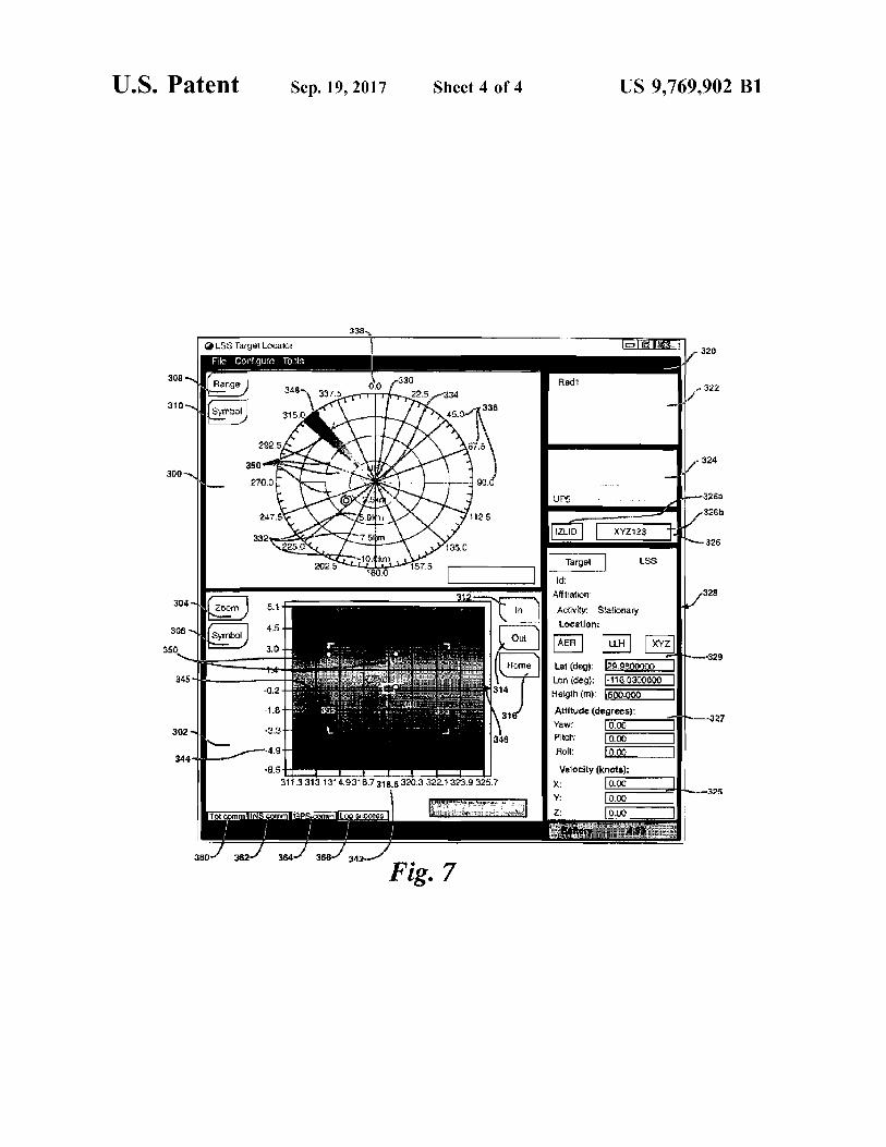
FIG . 7 is a user interface for a laser sensor stimulator . The disclosed laser sensor stimulator provides a low - cost , 30
agile means to support the development , testing , and peri DETAILED DESCRIPTION odic validation of ground and airborne laser sensors . It also can be used in environments where it may be advantageous As disclosed herein , a laser sensor stimulator 100 includes to stimulate airborne laser sensors during flight operations . a housing 102 , laser units 104 , 106 , a rifle stock 108 , a The laser sensor stimulator can illuminate sensors with 35 tactical foregrip 110 , an inertial measurement unit 112 , a multiple co - aligned lasers in a field environment through its sight 114 , laser switches 116 , 118 , auxiliary switches 120 , ability to track aircraft and receive tracking data pertaining and a control unit 122 . An umbilical cable 124 connects the to aircraft and items of interest to be tracked ( e . g . from a laser sensor stimulator 100 to a laser sensor stimulator flight test range ) . The laser sensor stimulator monitors the system described below . The housing 102 is a generally direction ( azimuth and elevation in which laser energy is 40 longitudinal shell that provides a platform for mounting the propagated with respect to a fixed frame of reference . The other components of the stimulator 100 . The laser units 104 , laser sensor stimulator also provides the exact spatial loca - 106 are attached to the housing 102 with one laser unit 104 , tion of an operator . The laser sensor stimulator tracks all 106 positioned on each side of the housing 102 with the three components ( aircraft position , laser sensor stimulator longitudinal axis of each laser unit 104 , 106 aligned with the pointing direction , and laser sensor stimulator position ) in 45 longitudinal axis of the housing 102 . The laser units 104 , real - time and provides this information to an operator in 106 are connected to the housing 102 via quick - release real - time via a novel user interface . For the system to be mounts ( not shown ) to permit rapid assembly and disassem operated safely for operators , aircrews , and other personnel , bly of the stimulator 100 and easy exchange of different laser certain system characteristics such as laser power levels units . The laser units 104 , 106 may be any portable laser or must meet local and federal safety regulations . The laser 50 emitter . The use of two laser units 104 , 106 permits opera sensor stimulator includes features that mitigate these risks tors to increase the total amount of energy emitted by such as safety lockouts based on laser safety parameters , stimulator 100 or to emit energy in different spectra simul laser keys , protective equipment , and software monitoring in taneously to test multiple sensors . Additional laser units may addition to procedural safety measures such as training . The be attached to the housing 102 to provide additional sources laser sensor stimulator records operational data concerning 55 and intensities of energy , different frequencies , and the like . its activities and activities of aircraft and other items of The housing 102 can include additional attachment areas for interest it tracks and synchronizes this data to a common additional laser units . The sight 114 is mounted along the top time code so the effectiveness of laser sensors , laser warning of the housing 102 so an operator can sight the laser sensor devices , and other devices that are stimulated by the laser stimulator 100 prior to powering the laser units 104 , 106 and sensor stimulator can be assessed . 60 during operation . The sight 114 can be a holographic site
A laser sensor stimulator comprises : a housing ; at least with night vision capability that dims the holographic image one laser unit removably attached to the housing ; an inertial during night operations so the sight 114 is compatible with measurement unit attached to the housing ; at least one night vision goggles . At least two of the laser units 104 , 106 switch for activating the at least one laser unit ; and a control and the sight 114 are adjustable along vertical and horizontal unit , wherein the control unit is connected to the at least one 65 axes to enable accurate bore sighting of the stimulator 100 . laser unit , the inertial measurement unit , and the at least one For example , if one of the laser units 104 is mounted in a switch to control operation of the laser sensor stimulator . fixed manner to the housing 102 , an operator can bore sight

US 9 , 769 , 902 B1
that laser unit 104 and then adjust the settings of other laser 100 are integrated into an intuitive design that operators can unit 106 and the sight 114 to match the fixed laser unit 104 . rapidly familiarize themselves with and operate effectively The sight 114 and the other laser unit 106 are adjustable in in a wide variety of environments . horizontal and vertical axes . The inertial measurement unit The laser sensor stimulator 100 can be connected to a 112 is attached to the housing 102 and provides real - time 5 computing device 210 that receives range data 240 from an absolute information concerning the orientation of the external feed and GPS data 256 . The computing device 210 stimulator 100 in terms of the azimuth and elevation in runs custom software that processes the range data 240 and which the stimulator 100 and hence the laser units 104 , 106 displays a user interface to provide an operator with situ are directed . ational awareness of the surrounding environment , airspace
The rifle stock 108 can be collapsible to permit adjust - 10 and the status of the stimulator 100 . The computing device ment for different operators and uses . The tactical foregrip 210 is connected to the stimulator 100 via the umbilical cord 110 provides a hand grip for an operator and also expands 124 and to an external power supply 220 such as a portable into a bipod 126 to support the stimulator 100 on the ground battery pack , a DC power supply , a vehicle power port , or an or other surface , if desired . A sling 128 can be attached to the AC power supply . The power supply 220 includes a con stimulator 100 for carrying the stimulator 100 or supporting 15 verter that steps down DC voltage and current for the it during operation . The sling 128 can be attached to a clip computing device 210 , or an AC / DC converter , depending 134 on the housing 102 , or it can be attached between the on the power source . The computing device 210 may be housing clip 134 and a clip 136 on the rifle stock 108 . The practically any computer , computer system , or program rifle stock 108 , the foregrip 110 , and the sling 128 are mable device , such as for example a laptop computer , ergonomic features that facilitate operation of the stimulator 20 multi - user or single - user computers , desktop computers , 100 from different positions such as , for example , aiming the portable computers and devices , handheld devices , network stimulator 100 from a shoulder - held position via the sight devices , mobile phones , and the like . In this example , the 114 , aiming the stimulator 100 in a shoot - from - the - hip computing device 210 comprises a portable laptop com configuration , or aiming the stimulator 100 from a prone puter . The range data 240 comprises data streams of aircraft position while supporting it on the bipod 126 . These ergo - 25 positions with GPS coordinates and other identifiers . The nomic features and lightweight construction of the stimula - computing device 210 receives and processes the range data tor 100 enable an operator to use the stimulator 100 for 240 and displays a user interface that enables operators to extended periods of time . The compact , modular design of identify , track , and acquire aircraft and other items of the stimulator 100 also enables rapid assembly and disas interest with the laser sensor stimulator 100 . A target 230 can sembly of the stimulator 100 for storing and shipping . 30 be used to calibrate the stimulator 100 prior to use . The
The control unit 122 comprises a circuit board and target 230 is positioned in the vicinity of the stimulator 100 associated electronics that are positioned inside the housing and GPS coordinates of the target 230 are obtained and 102 . The control unit 122 includes interfaces and command entered into the computing device 210 . Then , the stimulator and control electronics , as describe in more detail below . 100 is sighted on the target 230 and the calibration auxiliary The control unit 122 is connected to the inertial measure - 35 switch 120 is pressed . When this occurs , the inertial mea ment unit 112 by a cable 136 and to each laser 104 , 106 by surement unit 112 is calibrated based on the location of the cables 130 , 132 , to control and receive data from these target 230 and the stimulator 100 is ready for use . This components . The laser switches 116 , 118 are used to activate procedure provides a simple , reliable means for an operator each respective laser unit 104 , 106 . The laser switches 116 , to prepare a stimulator 100 for use . Operators also wear laser 118 may be buttons that an operator presses to activate a 40 eye protection ( LEP ) 270 for safety . laser unit 104 , 106 , or another type of actuator such as a The control unit 122 includes a microcontroller 301 , a single pole , double throw switch . The laser switches 116 , Global Positioning System / Inertial Navigation System 118 are connected to the control unit 122 , which provides a ( GPS / INS ) 302 , memory 303 , safety relays 304 , 305 , laser safety lockout that prevents operation of the laser units 104 , switches 116 , 118 , and auxiliary switches 120 , 121 with 106 when the laser switches 116 , 118 are pressed in certain 45 indicators 308 , 309 . The microcontroller 301 comprises one circumstances . The laser switches 116 , 118 are positioned or more processors ( e . g . microprocessors , central processing along a bottom , rear portion of the housing 102 to be units , arithmetic logic units , graphical processing units ) . The easily - accessible to an operator . The auxiliary switches 120 , microcontroller 301 is coupled to the memory 303 , which which are positioned on either side of the housing 102 , can may comprise random access memory ( RAM ) devices of the be programmed to provide a variety of functions including , 50 main storage of control unit 122 , as well as any supplemen for example , a calibration function that calibrate the inertial tal levels of memory , such as for example , cache memories , measurement unit 112 before the stimulator 100 is operated . non - volatile or backup memories ( e . g . programmable or The umbilical cable 124 provides power for the laser units flash memories ) , read - only memories , and the like . In this 104 , 106 and the control unit 122 , and provides a data link example , the memory 303 includes flash memory . The between the stimulator 100 and a computing unit 210 that is 55 microcontroller 301 is connected to , and communicates described below . with , the computing unit 210 via the umbilical cable 124 or
Depending on operational requirements , the stimulator a wireless interface , if desired . The laser switches 116 , 118 100 can include different combinations of the rifle stock 108 , are used by an operator to actuate the laser units 104 , 106 . the tactical grips 110 , the bipod 126 , and / or the sling 128 , The safety relays 304 , 305 are connected in circuit with the and different configurations of these components may be 60 laser switches 116 , 118 , and the laser units 104 , 106 and are used . Each component is detachably mounted to the housing controlled by the microcontroller 301 to provide a safety 102 . The modular design of the stimulator 100 facilitates lockout for the laser units 104 , 106 . The microcontroller 301 rapid repair and replacement of these and the other compo - can actuate the safety relays 304 , 305 to open the circuit to nents . The ruggedized construction makes the stimulator one or both laser units 104 , 106 and prevent either laser unit 100 resistant to extreme elements such as wind , rain , sand , 65 104 , 106 from operating when the respective laser switch dirt , dust , heat , and cold , and extreme environments . The 116 , 118 is pressed . Each auxiliary switch 120 , 121 has an ergonomic features and other components of the stimulator indicator 308 , 309 such as an LED light , that provides a

US 9 , 769 , 902 B1
visual indication when the auxiliary switch 120 , 121 is of the scope view and the azimuth of orientation of the actuated . The auxiliary switches 120 , 121 can be pro - stimulator 100 is shown as a field of view 348 . The per grammed to provide different functions including initial spective view 302 depicts an artificial horizon and the calibration and target cycling . For example , if the second stimulator 100 appears as in icon 340 at the center . The auxiliary switch 121 is programmed to provide target 5 perspective view 302 displays the elevation of the stimulator cycling , the field of view of the stimulator 100 cycles from 100 with respect to the horizon . The displays 300 , 302 are one target to another each time the second auxiliary switch updated in real - time as an operator uses the laser sensor 121 is pressed to help an operator sequentially track and stimulator 100 to track and acquire items of interest . acquire items of interest with the stimulator 100 . The lasers The scope view 300 and perspective view 302 include a maintain their original safety keys , arming switches , and 10 number of features that facilitate tracking and acquisition of notification LEDs . The microcontroller 301 receives inputs items of interest . In the perspective view 302 , these include from the safety keys and arming switches of the laser units the zoom feature 304 , which enables an operator or user at 104 , 106 and can lockout the laser switches 116 , 118 with the the computing device 210 to zoom in on a particular item . safety relays 304 , 305 to prevent the laser units 104 , 106 The zoom feature 304 helps an operator locate and acquire from lasing unless the keys are in place and the arming 15 items in the field of view . When zoom 304 is selected , the switch is in the “ On ” position . If any of these conditions is perspective view 302 displays In 312 , Out 314 , and Home not met , the microcontroller 301 activates the safety relay 316 buttons . The In 312 , Out 314 , and Home 316 buttons are 304 , 305 to open the circuit to the particular laser unit 104 , used to zoom in , zoom out , or return to a default Home 106 and prevent the laser unit 104 , 106 from operating setting that provides a preset field of view . The symbol Azimuth and elevation data is provided by the inertial 20 feature 306 enables an operator or user to remove or add measurement unit 112 to the GPS / INS 302 so the precise symbols to the perspective view 302 . These symbols include orientation of the stimulator 100 ( and laser units 104 , 106 ) the horizontal or X - axis 342 , which shows the orientation or is known . This data is fed to the computing device 210 azimuth in which the stimulator 100 is pointing . The values through the microcontroller 301 and umbilical cord 124 , of the horizontal axis 342 correspond to directional azimuths which also provides power to the control unit 122 . 25 336 displayed in the scope view 300 and the field of view
The computing device 210 operates under control of an 348 of the stimulator 100 , which is oriented at 318 . 5 degrees operating system and executes or otherwise relies on various in this example . The vertical or y - axis 344 of the perspective computer software applications , components , programs , view 302 displays the degrees of elevation of the stimulator objects , modules , data structures , databases , and the like . 100 relative to the horizon 345 . An arrow 346 indicates the The computing device 210 operates a main program 252 that 30 direction the stimulator 100 must move to acquire a par processes data from the stimulator 100 , range data 240 , and ticular item of interest that is being tracked . If items of GPS data 256 , controls the stimulator 100 , and provides a interest are programmed into the computing device 210 and user interface 254 . The main program 252 also maintains selected for tracking , the arrow feature 346 can be used with and accesses databases 258 of operational data for the a cycling function to help an operator quickly identify , track , stimulator 100 and the range data 240 and GPS data 256 . 35 and acquire different items of interest . The perspective view The range data 240 is processed by a message parser 250 , 302 also includes Tgt comm 360 , INS comm 362 , GPS which strips out pertinent data for the main program 252 to comm . 364 , and Log success 366 indicators . Tgt Comm 360 process . The parser 250 utilizes a plug - in architecture so indicates whether range date 240 is being received by the different versions can be used for different data feeds . The system . INS comm . 362 indicates whether the inertial mea main program 252 processes the parsed range data 240 and 40 surement unit 112 is operating and providing data to the creates a list of aircraft , aircraft , vehicle , and other items of system . GPS comm 364 indicates whether GPS signals are interest that the stimulator 100 can track and acquire . It being received by the system . Log success 366 indicates displays icons and other information via a user interface 254 whether the system is logging data about the operation of the on the computing device 210 . The program 252 continually stimulator 100 . monitors inputs and operational information from the laser 45 The scope view 300 provides a 360 degree or bird ' s eye sensor stimulator 100 including actuations of the switches view of the orientation of the stimulator 100 . The center 330 116 , 118 , 120 , 121 and information from the inertial mea of the scope view 300 represents the location of the operator surement unit 112 . It also controls the lasers 104 , 106 and and the stimulator 100 based on GPS coordinates of the updates the user interface 254 in real - time . The GPS position computing device 210 . From the center 330 , each concentric of the operator is provided by an on - board GPS antenna ( not 50 ring displays the range 332 , which is shown in 2 . 5 km shown ) within the computing device 210 . The GPS antenna increments in FIG . 7 . The range feature 308 changes the may be a separate device or it may be positioned on the ranges 332 shown in the scope view 300 . In FIG . 7 , the range stimulator 100 . The GPS antenna receives GPS time codes 332 is set at 10 km in 2 . 5 km increments and the scope view 265 and uses those to determine its position . The main 300 displays items of interest in that range . When the range program 252 combines GPS time codes 256 with parsed 55 feature 308 is selected , preset ranges appear and an operator range data 240 and stimulator 100 information to record all can select ranges of 1 km , 10 km , 30 km , or 50 km , with events and uses of the stimulator 100 in time sequence and corresponding increments such as 0 . 25 km for a 1 km range store the data in a database 258 for recall and processing . or 7 . 5 km for a 30 km range . This feature helps operators This processing provides a complete time - stamped log of all track and acquire items of interest in particular ranges . The operations of the stimulator 100 in a particular environment 60 scope view 300 also displays a safety zone 334 around the and event . The user interface 254 provides a graphical center 330 . The safety zone 334 designates an area in which depiction of the local airspace and environment with accom - the laser units 104 , 106 cannot be activated . If the stimulator panying visual and audio status information for the laser 100 is aimed at items of interest in the safety zone 334 , the sensor stimulator 100 and items of interest . The primary main program 252 locks out the laser triggers 116 , 118 , via displays of the graphical user interface 254 include an 65 the safety relays 304 , 305 to prevent the laser units 104 , 106 overhead or scope view 300 and a perspective view 302 . The from lasing . An audible sound can be played to alert an operator and stimulator 100 are positioned at the center 330 operator that the stimulator 100 attempted to engage an item

US 9 , 769 , 902 B1
within the safety zone and is locked out . Depending on the the vicinity of the user point . The laser status box 326 strength of the laser units 104 , 106 , the operational envi - indicates which laser units are attached to the stimulator 100 ronment , items of interest , and other factors , the safety zone and provides their current status . When a laser unit 104 , 106 334 may be adjusted to provide the necessary degree of is activated , the associated laser indicator 326a , 326b is operational safety for use of the stimulator 100 . The field of 5 illuminated in the laser status box 326 . The statistics box 328 view of the stimulator 100 appears as a highlighted portion displays data for a currently - selected item of interest and the 348 that expands as range increases . When the laser units laser sensor stimulator 100 ( labeled “ LSS ” ) . The unique 104 , 106 are operated , the field of view 348 is illuminated . identifier of the item of interest , its affiliation as friend , foe , As shown in FIG . 7 , the stimulator 100 is oriented at about or unknown , and activity can be displayed with the location 318 degrees . A safety zone of permissible azimuths may be 10 329 in different coordinate systems . In FIG . 7 , the geo defined and the main program 252 will lockout the laser graphic coordinates of latitude , longitude , and height are triggers 116 , 118 if an operator attempts to engage items outside the permissible azimuths . An audible sound can be displayed . The target data 329 also can display coordinate
locations in XYZ coordinates of an item or interest . The played to alert an operator that the stimulator 100 is aimed outside of permissible azimuths and is locked out . The field 15 ani eld 15 attitude 327 and velocity 325 of items of interest are of view 348 may be highlighted in a particular color when displayed to aid in target acquisition and confirmation . In the stimulator 100 is pointed at an unauthorized azimuth or this case , the statistics box 328 displays attitude 327 and locked out and when the stimulator is operated . The symbol velocity 325 for UP5 , which is stationary . The data box 320 feature 310 serves the same purpose as on the perspective also shows the battery voltage 323 of the system and view 302 to add or remove features from the scope view 300 20 provides an alert if the voltage nears or drops below required such as the azimuths , 336 and the range 332 . True north is levels . at 0 . 0 degrees 338 . If one or both laser units 104 , 106 is activated , the field of
These features of the scope view 300 and perspective view 348 is highlighted in red or another color as are the view 302 enable operators to rapidly identify and track items field of view indicators 355 in the perspective view 302 . An of interest . The directional azimuths 336 show the position 25 audible sound may be played to indicate activation of one or of items of interest in relation to the field of view 348 of the both laser units 104 , 106 . The laser status 326 displays each stimulator 100 and provide an azimuth to acquire a particu - operational laser unit 326a , 326b in green . The selected lar item of interest . Once the stimulator 100 is aligned along target location , laser on / off state , and GPS time are all the azimuth for an item of interest , the perspective view 302 recorded to a database running in the background for later can be used to acquire the item for lasing . To promote rapid 30 review to determine whether a particular item of interest was identification , items of interest can be color - coded according engaged by the stimulator 100 . to their status , such as for example , red for opposition , blue The stimulator 100 and system can be employed in the for friendly , green for unidentified , and orange for user following manner . An operator and spotter transport the points . Items of interest can be highlighted in the scope and stimulator 100 and system to a site whether it will be perspective views 300 , 302 for more rapid identification and 35 operated . They unpack and assemble the stimulator 100 and tracking . The field of view 348 of the stimulator 100 is based system . They mechanically configure the stimulator 100 and on outputs of the inertial measurement unit 112 and dis - establish the range data feed 240 and GPS feed 256 for the played as a slice 348 emanating from the operator ' s position site . They install a bore sight target 230 and obtain its GPS 330 at the center of the scope view 300 . The field of view coordinates . The laser units 104 , 106 and the sight 114 are 348 is displayed in the perspective view 302 by four field of 40 aligned and laser power is verified and calibrated with laser view indicators 355 that bracket the stimulator ' s field of power meters if desired . Then , they initiate the computing view to indicate the approximate region that receives energy system 210 and the user interface 254 . User point data is from the laser units 104 , 106 . An icon 340 at the center of input for the bore sight target 230 and other points of interest the field of view indicators 355 represents the stimulator 100 324 . The operator calibrates the IMU unit 112 with this data and its point of focus . When the stimulator 100 acquires an 45 by pressing the auxiliary switch 120 . The safety relays 304 , item of interest , the item appears within the stimulator icon 305 are configured to provide a specified safety zone 334 for 340 , the stimulator icon 340 is highlighted , and an audible operation of the laser units 104 , 106 . The operational sce sound is played . narios can vary . In one scenario , a spotter determines which
The user interface 254 displays other operational infor - items of interest to display on the user interface 254 . The mation in a data box 320 extending along a right portion of 50 spotter calls out appropriate heading and elevation to the the user interface 254 . The data box 320 lists items of operator who directs the stimulator 100 onto the item of interest 322 within range of the stimulator 100 . The in - range interest . The operator aligns the sight 114 on the item of items are pulled from the range data 240 and indexed on interest and confirms the item with the spotter . At this point , unique identifiers reported by the range data 240 . Custom the operator can engage the item such as an aircraft and its handles can be applied to each item of interest for easier 55 laser sensors or warning devices by activating the laser units identification . For example , an assigned identifier of 104 , 106 with switches 116 , 118 . The operator can continue " XYZ12345ABC ” can be given a custom call sign of lasing from a standing rifle stance , a shoot from the hip “ Redl ” . The individual identifiers can be displayed in dif - stance , or other position or the spotter and operator can track ferent colors to indicate their status , as described above . The and acquire other targets or cease engagement after a par user points 324 displays user - defined points such as UP1 , 60 ticular time has elapsed . In another scenario , the operator UP2 , UP3 , UP4 , UP5 , UP6 shown in FIG . 7 . GPS coordi - identifies an item of interest through observation using the nates are entered for each user point 350 and an operator can sight 114 or night vision goggles . The operator aligns the use them to aim , orient , or calibrate the stimulator 100 . For s ight 114 with the item without firing the laser units 104 , example , GPS coordinates of a hill or tower can be entered 106 . The spotter evaluates the stimulator 100 heading and into the main program 252 as user points that can be used to 65 confirms the suitability of the item for engagement . The calibrate the stimulator 100 or provide features for rapid operator can engage the item and its sensors and other orientation of the stimulator 100 onto an item of interest in devices after spotter confirmation . The operator and spotter

US 9 , 769 , 902 B1 10
continue to monitor the situation and cease engagement if described to best explain the principles of the invention and necessary or once maximum time has elapsed . its practical applications to thereby enable other persons As seen from the foregoing disclosure , the laser sensor skilled in the art to make and use the invention in its various
stimulator offers a unique capability to engage and stimulate forms and with its various modifications as are suited to the laser detectors , sensors , and warning receivers of aircraft 5 pa raft 5 particular uses contemplated . The scope of the invention is in - flight , vehicles in transit , and other items of interest . It to be defined by the following claims .
What is claimed is : provides this functionality in a compact , portable system 1 . A laser sensor stimulator , configured to stimulate a laser that is easy to assemble and operate with safety features to protect operators and other personnel involved . The ergo sensor , the laser sensor stimulator comprising :
10 nomic design , graphical user interface , and other features of 10 a housing ; the system make the task of training operators to use the a laser unit removably attached to the housing ; system straightforward with little prior experience or exper an inertial measurement unit attached to the housing ; tise required in the use of lasers or tracking . The modular a switch for activating the laser unit ; and design of the system allows customized configurations to a control unit - in electrical communication with the laser support a wide range of detectors at relatively low cost and 15 unit , the inertial measurement unit , and the switch , the minimal manpower . The laser sensor stimulator provides control unit configured to control and receive data from high - quality , reliable and traceable laser sensor stimulation at least one of the laser unit and the inertial measure via direct illumination . It includes numerous features that ment unit . give it unique capabilities including by way of example and 2 . The laser sensor stimulator claim 1 , further comprising : not limitation , ground and air target stimulation capability 20 a sight attached to the housing ; operational from short to medium range of 10 - 20 km an adjustable rifle stock attached to the housing ; and depending on the range and strength of the lasing units . This a foregrip attached to the housing , the foregrip including range can be extended by using stronger lasers . The laser a retractable bipod , units can be reconfigured for different missions depending wherein the rifle stock and the foregrip provide an ergo on the strength and frequency of laser unit desired . The 25 nomic design to permit operation of the laser sensor absolute location and pointing attitude measurement stimulator in a standing rifle position or a prone posi together with the time logged recording capability of the tion .
3 . The laser sensor stimulator of claim system provide enhanced precision for laser sensor valida 1 , wherein the tion , laser state recording , and day and night compatibility control unit includes safety relays in electrical communica and operation . The laser sensor stimulator ' s modular archi - 30 " archi 30 tion with the switch to prevent operation of the laser unit .
4 . The laser sensor stimulator of claim 1 , further com tecture reduces cost and improves its manufacturability . The portable design makes it easily transported and provides for prising an auxiliary switch , wherein the auxiliary switch is simple , rapid setup and operation by one or two persons . The in electrical communication with the control unit for cali ergonomic physical design and dynamic user interface and brating the laser sensor stimulator and the inertial measure controls improve operation and performance within a rug - 35 ment unit . gedized construction that provides shock / vibration protec 5 . The laser sensor stimulator of claim 1 , further com tion , moisture resistance , and the capability of operating in prising : extreme temperatures and environments . Additional safety a computing device connected to the laser sensor stimu measures include an automatic safety interlock for the laser lator and the control unit via an umbilical cord , units based on reconfigurable safety criteria . The stand - 40 40 wherein the computing device receives range data includ alone , host - controlled , and master / slave configurations and ing data streams of aircraft positions and other identi operation enable the laser sensor stimulator to be used in a fiers and GPS data from external feeds ,
wherein the computing device further receives status and complete spectrum of research , development , test , and evaluation activities . The system can be powered by DC or operational information from the laser sensor stimula AC power sources or batteries . The laser sensor stimulator 45 tor , and also includes a modular extensible software architecture that wherein the computing device processes the range and provides bi - directional interfacing with standard civilian and GPS data and the status and operational information to defense department range data feeds and telemetry formats , create a user interface of an operational environment operator situational awareness and target location , audible and operation of the laser sensor stimulator . alerts and target position call - outs , sure - safe operation with 50 with 50 6 . The laser sensor stimulator of claim 5 , further com keep - out regions and target - to - target proximity alerts , GPS prising a DC or AC power source for powering the laser time - correlated mission event logging for post - test data sensor stimulator and the computing device , wherein the
reduction , and mission replay . power source includes a converter for converting the DC or AC power source to a DC source for powering the comput The foregoing disclosure has been presented for purposes
of illustration and description and is not intended to be 55 in se 55 ing device , the control unit , and the laser unit . exhaustive or to limit the disclosure to the devices , systems , 7 . The laser sensor stimulator of claim 1 , wherein the methods , and forms disclosed herein . Persons skilled in the control unit is configured to lock out the laser unit and play art will realize and appreciate that many modifications and a sound to alert an operator when the laser sensor stimulator variations are possible in light of the above teaching . For is aimed at an item of interest within a predefined safety example , although the laser sensor stimulator was illustrated 604 ugh the laser sensor stimulator was illustrated 60 zone or outside of a predefined azimuth . with two laser units , it can be configured more or less laser 8 . The laser sensor stimulator claim 2 , further comprising : units depending on the application and capabilities desired . a strap attached to the housing , Moreover , other emitters and energy sources may be wherein the rifle stock and the strap further provide an attached to the stimulator to emit energy for testing other ergonomic design to permit operation of the laser types of sensors and warning devices . The disclosed meth - 65 sensor stimulator in a shoot - from - the - hip position . ods and associated apparatuses and their variations were * * * * *