maharashtra jeevan pradhikaran - e...
TRANSCRIPT

Contractor No. of corrections Executive Engineer
93
MAHARASHTRA JEEVAN PRADHIKARAN
MAHARASHTRA JEEVAN PRADHIKARAN
URBAN & RURAL SCHEME CIRCLE, THANE
MAHARASHTRA JEEVAN PRADHIKARAN URBAN & RURAL SCHEME DIVISION VIRAR
Name of work :. Shifting of M.S. Pipe line of 790 mm dia, 6.4 mm thick
obstructing road widening from Walive Phata to Gokhivare Phata Vasai.
DETAILED ITEMWISE SPECIFICATIONS ITEM No. 1 Providing, fabrication and Transportation M.S. pipes of various dia
from contractors materials as per IS:3589:2001 and IS:5504 (Latest version)
SCOPE The scope or special specifications shall cover the following works under the contract. Fabricating M.S. pipes of M.S. pipes of various dia (O.D.) with required thick M.S. plates and testing by the pipes by any approved agency of MJP. The agency for third party inspection will be fixed by the Superintending Engineer. The work includes transporting of fabricated pipes from factory to laying site. PROVIDING M.S. PIPES 1. Pipes to be supplied under this contract shall conform to IS:3589:2001 for
welded Steel pipes for water, subject to specific requirements given below.
2. In case supplier propose to supply pipes to the Standards superior to the above standards no weightage will be given evaluating the bid and for payment.

Contractor No. of corrections Executive Engineer
94
Specific Requirement i) Method of Manufacture
a) Electric resistance welded (ERW) b) Electric Fusion (Arc) welded (EFW) ii) Applicable standards (with latest edition) IS:3589-2001 & IS:5504-Latest Revision, Code of practice for
laying and jointing M.S. pipes iii) Inspection Inspection of M.S. pipes is divided in two parts Inspection during manufacturing a) Testing and identification of plate/strips material for
manufacturing b) Qualification of welding process to be used manufacturing
of pipes. c) Qualification of welders d) Dimensional check before start of welding to avoid rejection
at a later stage. iv) Inspection of Ready Built Pipes - This consists of : 1. Visual inspection,
2. Dimensional check,
3. Hydraulic pressure tests
4. Mechanical tests -
a) Tensile test
(b) Flattening test (for ERW/EFW pipes only);
(c) Guided bend test for pressure

Contractor No. of corrections Executive Engineer
95
v) Testing and Acceptance Criteria Visual Inspection : All pipes shall be free from defects such as cracks surface flaws,
laminations, etc.. The ends shall be cleanly cut and reasonably square with axis of the pipe
vi) Dimensions and Tolerances - The dimensions such as O.D and thickness shall conform to the
requirement of order as per applicable specifications. The tolerance are as under :
Outside diameter and length Pipes Body - The tolerance on pipe body shall be as under. Nominal Size Tolerance 1550/1296 +0.75% Pipe Ends Ovality for distance of 100 mm from the end of the pipe shall be as
below. Upto and including 250 mm + 1.6 mm - 0.4 mm Over 250 mm + 2.4 mm - 0.8 mm Thickness
Though it is specified in IS:3589-2001, no negative tolerance for thickness of plates of M.S. pipes is permitted as far as this contract is concerned.
The thickness will be verified by Ultrasonic thickness gauge. The thickness for 790 mm dia pipe should be 6.4 mm thick.
vii) Straightness Finished pipe shall not deviated from straightness by more than 0.2
percent of the total length or 6 mm whichever is lower.

Contractor No. of corrections Executive Engineer
96
viii) Hydraulic Pressure Test Each pipe shall be hydraulically tested at manufacturer’s work shop
for Hydraulic test pressure is calculated from the formula 2ST P = D Where P = Test pressure in Mpa S = Stress in Mpa which is taken as 60% of the specified
minimum tensile strength T = Specified thickness in mm D = Specified outside diameter in mm ix) Mehanical Test Sampling The procedure for sampling of pipes for various tests and criteria
for conformity shall be as given in IS:4711:1974. x) Tensile Test Tensile test shall be carried out as per IS:1894:1972. The parent
metal of pipe is subjected for measurement of ultimate tensile and elongation properties. Another sample is taken for testing of strength of the weld, the ultimate tensile of which should normally be more than or equal to ultimate tensile of parent metal. However, the minimum mechanical properties as per IS:3589:2001 should be as under.
Steel Grade Tensile Strength Percentage elongation (Fe) (Min.MPa) (Min) 410 410 18

Contractor No. of corrections Executive Engineer
97
xi) Fattening Test : (For ERW Pipes) :
A ring not less than 40 mm length taken from one end of each
selected pipes shall be fattened between two parallel plates. The test shall be taken by keeping the weld at 90 Degree to the direction of the force. No opening shall occur by fracture in the weld until the distance between plates is less than 66% of original O.D of pipe and no cracks or breaks on the metal elsewhere that in the weld shall occur until the distance between the plate is less than 33% or original O.D of pipe.
The approved pipes are stamped on one end for identification by
inspecting authority and documented accordingly in despatch document.
Steel’s Tensile Requirements - Standard IS:3589-2001 Fe 410 MPa grade steel Ultimate Tensile 410 MPa strength Yield stress 2600 Kg/Sqcm Design requirements Internal pressure (Factory Test Pressure)
For 790 mm dia pipes 2.53 Mpa
Design pressure taken should be maximum of the following a) 1.5 times maximum working pressure. b) Sum of maximum working pressure plus surge pressure. However, the design pressure should not exceed 5 Mpa as per
IS:3589-2001 specifications.

Contractor No. of corrections Executive Engineer
98
Allowable Stresses to be used Particulars IS:3589-2001
Specification pipes
Specified minimum Yield stress For combined bending and direct Compression for design test pressure without considering surge (i.e. for 1.5 times working pressure only)
2600 Kg/Sqcm. 1300 Kg/Sqcm.
For combined bending and direct tension for design test pressure without considering surge (i.e. for 1.5 times working pressure only)
1560 Kg/Sqcm.
For design pressure considering sum of working and surge pressure.
1950 Kg/Sqcm.
In the event of conflict between the clauses mentioned herein and
relevant IS codes, provisions of the above specification shall prevail over.
xi) Condition of supply The pipes shall be supplied with one shop coat of red oxide
confirming to IS:2074 internally and externally. At any time during execution the supply of pipes should not exceed 1500 meters in length over the laid length of pipes in case of all diameters.
DRAWINGS Fabrication drawings shall have to be prepared by the contractor taking into consideration the sizes and lengths of the M.S. Plates, flats etc. The third party and MJP should approve the drawing for fabrication of pipes as per specifications in IS:3589:2001. The pipes should be manufactured by contractor as per approved drawing. All dimensions should be specified as per detailed specifications.

Contractor No. of corrections Executive Engineer
99
FACTORY The factory should be equipped with all necessary electrical and mechanical equipment for carrying out various operations involved in the work under the tender, such as rolling, automatic welding, cutting, testing etc. The tenderer shall fabricate pipes and specials at factory and transport them to the laying site. The factory shall be equipped with at least the following minimum number of various equipment and plant. A) Plate bending machine for rolling of pipe drum. i) for pipes upto 1300 mm dia 1 No. for plates 5 to 12 mm thick B) Automatic welding machine i) For welding joint of steel plates of the required thickness For inside welding 1 No. For outside welding 1 No. C) Hydraulic testing machines Testing machine capable of testing 1 No. of length to be fabricated D) Adequate gantry or crane of required 1 No. capacity E) Channel bending machine suitable for 1 No. rolling ring girders for pipes of the required diameters. F) Lathe for machine flange rings 1 No. plates etc. G) Lathe for machine expansion joints 1 No. of required diameter.
Contractor No. of corrections Executive Engineer
100
H) Mobile crane for loading, unloading Adequate of pipes for the Job. I) Cold pressing equipment for plates 1 Set of the required thickness to required curvatures The intending contractor shall have to satisfy the authorities about his capacity to fabricate or get fabricated the pipes and specials as covered in the tender scope, within the time specified. The factory shall have to provide minimum equipment as listed above and additional equipment, if required to maintain Schedule progress on the work, if the Engineer so directs. Adequate fabrication facilities for specials and for testing shall be provided. PIPE SUPPLY OF MATERIALS The MJP will not supply M.S. Materials such as plates, flats etc. required for the fabrication of pipes. All requirement of such materials will have to be arranged by the contractor from open market. The plates required for fabrication of M.S. pipes under this tender shall confirm to IS:2062 Grade 'B' Fe410. The conveyance of fabricated material from workshop to site of work shall be deemed to have been covered in the relevant items of fabrication of pipes, specials etc. The contractor should note that the steel plates and other structural steel required for fabrication of specials is to be procured by him from open market at his cost. The contractor has to procure such plates in several stages as the circumstances demand, or, as directed by Engineer-in-Charge. The Pradhikaran shall not however supply any steel or structural steel to the contractor for his use for preparing jigs, testing arrangements, platforms etc. in the factory or in the field. The contractor shall have to make his own arrangements for procuring them at his own cost immediately on receipt of work order and the Pradhikaran shall not entertain any request for extension of completion period or compensation on increase in cost etc.

Contractor No. of corrections Executive Engineer
101
SPECIFICATIONS FOR FABRICATION OF PIPE CUTTING OF PLATES TO SIZE The pipe drums shall normally be fabricated with only one longitudinal joint. However, if the plates of exact size are not available, the contractor shall fabricate pipe drums with two longitudinal joints at the approval of the Engineer The plates shall be cut on all the four sides to the exact dimensions and shape required by a suitable plate cutting machine such as oxyacetylene cutting machine of Guillotine for fabrication of pipe drums. Tolerance in cutting shall not be more than +3 mm in width and length. After rolling/bending all the edges of the plates shall be cleaned by brushing, grinding. The standard length of fabricated pipes shall be in meters. The plates shall be given a bevel at the edges depending upon the welding machine to be used by the contractor. Ends of the pipes fabricated shall necessarily have 'V' edges, with an included angle of 75o + 2.5o in case of manual welding as in the field, manual welding is to be done.. For pipes of diameter less than 1200 mm the bevel shall generally be from outside. In case, where Engineer specifically orders so, bevel shall be from inside also for diameters less than 1200 mm. In the factory where automatic machine having sufficient penetration is used the edges in the pipe may be square cut. The type of joints to be adopted in the factory shall depend on the type of welding machine to be used and the method of welding to be adopted. Experimental welding shall be demonstrated by the contractor to the Engineer-in- Charge in the factory and testing of samples there from shall be done by the Engineer-in-Charge at contractor's cost before finally deciding the voltage and current characteristics for proper welding to be adopted. After the plates are cut, the edges shall be made smooth to remove all inequalities by means of polishing grinder. Care shall be taken to see that cut edges of the plate are perfectly straight. Jigs to be used for this purpose shall depend on the cutting machine used. The correctness of the cutting shall be checked before the plates are rolled into pipe drums. Corrections if any shall be made and re-cutting done, if necessary. If any plate or flat is found to be warped, the defect shall be removed by putting the plate into roller press at the contractor's cost. If the contractor finds that some of the plates are laminated or are badly corroded, these shall be stacked separately and shall not be used for fabrication of pipes etc. The contractor shall not be entitled for any extra claim on

Contractor No. of corrections Executive Engineer
102
account of handling and cutting plates, which are subsequently rejected by the Engineer. Marginal cutting as well as left over pieces of plates and other steel sections shall be collected by the contractor and stacked separately in the yard. ROLLING OF PLATES The plates cut to exact size shall be put into rolling machine to form the pipe drum of the required diameter. The contractor shall adjust the rolling machine so as to give a uniform curvature to the pipe drum throughout its circumference. The curvature shall be checked by the contractor's foreman during the process of rolling and rolling shall be repeated till such stage that exact curvature is obtained. Contractor shall roll the pipe drum even after longitudinal welding is done, if proper curvature is not obtained any testing on weld shall be carried out only after welding or rerolling of pipe, if required. Heating of plates shall not be allowed to have the desired curvature. TACKING OF DRUMS Rolled drums shall then be taken to the assembly platform for tacking for longitudinal welding. Where machine welding is to be done there shall be no need to have a gap between the faces depending upon penetration obtained. If hand welding is permitted by the Engineer, gap shall be between 2 to 4 mm. Clamp spiders, tightening rings or any other approved gadgets shall be used during assembling and tacking. The contractor shall put serial numbers, plate thickness and letter MJP inside the drums before these are tacked. The tacked drums shall then be taken to the assembly platform for tacking them to make pipes of 6 meter lengths. Maximum length shall not exceed 12 meters and the contractor shall comply with such orders without claiming any additional cost for the same. During tacking, care shall be taken to see that the longitudinal joints of abutting pipe drums are staggered as 90o as shown on the drawing. The assembly shall be truly cylindrical and without kinks, the faces being exactly at right angles to the axis of the pipe. The contractor shall provide at his cost suitable gadget to check the correctness and shall be as per Para 8 of IS:3589.

Contractor No. of corrections Executive Engineer
103
WELDING OF PIPES Assembly as described above shall then be transferred to an automatic welding machine of approved make for full welding. All the circumferential joints as well as longitudinal joints shall be done on automatic welding machine only. The Engineer may, at his discretion allow hand welding only for the sealing run or for some minor welding. The Engineer-in- Charge, during the progress of work, shall issue working drawings or instructions specifying the details of welding joints for the different fabrication work. Electrodes of approved make conforming to IS:814 and size only shall be used for welding depending upon the thickness of the plates and the type of joint. The current and the arc voltage required for the machine shall be decided after the experimental welding is done. All expenses for these experiments shall be borne by the contractor. The current and the arc voltage once decided shall not be altered, without the permission of the Engineer-in-Charge for that particular thickness of plate. The welding shall conform to IS:822 and 823. In case of thin plates gas welding may be resorted to. Gas welding also shall be subject to the same specifications and tests as those for the electric welding. The welders employed by the contractor shall be sufficiently experienced and qualified as per relevant IS in welding works to execute the works of standards as specified in IS:817 and type of welding work carried out particularly for this type of work. Their work shall be tested by the Engineer-in-Charge before they are entrusted with the job and also from time to time during the progress of the work. The contractor shall keep the record of welding as may be prescribed by the Engineer-in- Charge to enable him to know the performance of each welder. Only the person permitted by the Engineer-in-Charge shall carry out welding work. Hand welding shall preferably be carried out by a pair of welders. A joint entrusted to a particularly individual or a pair shall as far as possible be completed only by them in all respects including sealing run. WELDING JOINTS ELECTRODES Welding electrodes to be used for welding in this contract shall conform to the Indian Standard Specifications IS:814 (Specification for covered electrodes for metal arc welding of mild steel). The contractor shall use standard electrodes, depending on the thickness of the plate to be welded and the type of joint. The contractor shall also use standard current and arc voltage,

Contractor No. of corrections Executive Engineer
104
required for the machine as per the Manufacturer's directions. The contractor will use only the approved welding consumables by MJP. TYPE OF WELDING JOINTS The circumferential joints of the pipes shall be butt welded, with required number of runs internally and externally. All fillet welds shall have a throat thickness not less than 0.7 times the thickness of the pipe to be welded. WELDING PROCEDURE All parts of pipes, specials, etc. shall have all loose scale, slag, rust, paint and any other foreign material removed with wire brush and left clean and dry. All scale and slag shall be removed from each run of weld when that run is completed. Welding shall conform to relevant provisions of IS:3589 and IS:816:1969 or Latest Version. TESTING OF WELDED JOINTS Welded joints shall be tested in accordance with procedure laid down in Indian Standard Specifications IS:3600, (Code of Practice for Testing Fusion Welded Joints and Weld Metal in Steel). At least one test specimen shall be taken out for testing, per ten joints done. Test pieces shall be taken out from the places pointed out by the Engineer. They shall be machined and tested as early as possible. The shape of the test pieces removed for testing shall be such that it shall give the specimen of the required dimensions with the weld in the middle of the specimen and at same time leave the hole in the pipe with rounded corner. This hole shall be patched plated with a plate of suitable size cut from a separate pipe of same diameter. It must ensure good butt weld. TENSILE TEST The test specimen taken perpendicularly across the weld shall be shaped in accordance with Indian Standard Specifications IS:223. The tension test specimen shall be machined. The protruding welded portion from inside as well as outside shall be removed by machining before the specimen is tested. If the specimen shows defective machining or develops flaws not associated with welding, it shall be discarded and another specimen substituted. The welded joint shall show a strength not less than the minimum tensile strength for the plate in accordance with IS:2062-1992.

Contractor No. of corrections Executive Engineer
105
BEND TEST Bend test specimen shall also be prepared in the same fashion as the tensile test specimen. The specimen shall stand being bend cold through 180o around a pin that has a diameter equal to 4.5 times the plates tickness without developing cracks. For this test, face representing inside of the pipe shall be placed next to the pin. TRE-PANNED PLUGS Tre-panned plugs shall be taken out from any welded portion as pointed out by the Engineer. These plugs shall not show any defects in welding such as inclusion of slag, blow holes, cavities, etc. The plug shall be 12 mm in diameter and shall be taken out by means of suitable electrically operated hack-saw. Such holes in the pipe shall either be filled back by inserting a steel stud and welding around or threading the hole and providing suitable G.I. plug. This test shall be done only if considered necessary by the Engineer. PROCEDURE ON FAILURE TEST SPECIMEN If the test specimen fails in either tensile or bend test or in both, two additional test specimen shall be taken out from the same section and shall be tested for tensile and bend tests. If any one of them fails, extensive gousing and rewelding shall be done for the welded joints in that section to the full satisfaction of the Engineer. However, if both the samples give satisfactory result, the joint from which the original sample was taken and had failed shall be repaired to the satisfaction of the Engineer, by gousing and welding etc. at contractor's cost. Welder, who had done the welding of the joint that has failed shall be solely held responsible. Since all other factors like electrodes, current, arc voltage etc. are already controlled, negligence on the part of the welder only is responsible for such failure. For first such failure the welder shall be warned and if the welded joint done by him fails for the second time, he shall be removed from the job.

Contractor No. of corrections Executive Engineer
106
WORKMANSHIP All pipes shall be fabricated out of steel plates of Fe.410 grade and shall be free from excessive pitting, crack surface flaws, laminations or any other defect. All such defective plates shall be stored separately and should not be used. All the pipes shall be properly stored in different stacks size-wise. The pipes shall be truly cylindrical and straight in axis, acceptable tolerance being as per IS:3589. The ends of the pipes shall be accurately cut with level for field welding depending on sizes as specified earlier. The tolerance in outside diameter for leveled and for butt welding shall be as per Table 2 Para 12 IS:3589. In case of pipes to which flange adopters are to be fixed, the external diameter of the pipe shall not be more than + 1 mm than the theoretical one. The contractor shall have to roll the pipes several times to achieve this accuracy. The longitudinal welding at the ends of the pipes shall be ground smooth and flush with the plates for atleast a length of 200 mm from the ends. No additional payment shall be made for re-rolling or grounding the welds as described below. Any minor repair in welding that is required to be done, shall be done only after obtaining the permission from the Engineer-in-Charge. Whenever he finds that the work has not been done by the contractor as specified above and to his satisfaction, and the pipes fabricated have injurious defects, these shall be liable for rejection. No payment shall be made to the contractor for such fabrication and welding and the cost of such wastage shall be recovered from the contractors bills on this account. Decision in this regard of the Engineer-in-Charge shall be final and binding on the contractor. TEST ON WELDS The test on welds shall conform to Para 14 of IS:3589. The testing for tensile bend and flattering test for circumferential joints shall confirm to para 14 of IS:3589. HYDRAULIC TESTING OF FABRICATED PIPES AT FACTORY The pipe length fabricated shall be as specified earlier above. The contractor shall provide all the required machines and apparatus for testing all the pipes at the factory. The arrangements made by the contractor for hydraulic testing of pipes shall be subject to the approval by the Engineer. The contractor shall paint inside the serial number of pipe, the diameter and the plate thickness and letters 'MAHARASHTRA JEEVAN PRADHIKARAN' as

Contractor No. of corrections Executive Engineer
107
well as the date of the test etc. as directed by the Engineer. The pipes shall be inspected thoroughly before testing for any apparent defect in welding and the contractor shall repair such defects by gousing and rewelding. Such pipes will be laid only on approval of the Engineer-in-Charge. Necessary provisions for storage tank for water for testing, water pumping arrangements, if necessary and making available the required water shall be made by the contractor. Hydraulic testing of pipe manufactured will be done by inspection through third party at the fabrication site and to the satisfaction of the Engineer-in-Charge or his authorised representative. Third party will be approved by MJP and charges for pipe testing will be borne by the contractor. Accurate pressure gauge of approved make shall be mounted on one end of the pipe to indicate the pressure inside the pipe being tested. Each pipe shall be tested to the test pressure as under and as per IS:3589-2001. For M.S. pipes � 12 Kg/Sq.cm. The Engineer at his discretion may accept untested pipes if the total length of fabricated pipes of that particular diameter is less than 50 meters. The pressure shall be applied gradually by approved means and shall be maintained atleast for 10 minutes or till inspection by third party approved by MJP and Engineer-in-Charge during which time, the pipes be hammered throughout its length with sharp blows with 1 kg. hand hammer. The pipe shall stand the test without showing any sign of weakness, leakage, oozing or sweating. If any leakage is observed, on approval of Engineer-in-Charge, it shall be repaired by gousing and rewelding or as directed by him. No separate/additional payment shall be made for dewatering, gousing, repairing and retesting and the handling required to be done for such pipes. MEASUREMENT AND PAYMENT FOR PROVIDING AND FABRICATING OF PIPE The providing and fabrication of pipes shall be measured in Running meter of pipes fabricated and shall include the cost of supplying all the labour, material, machinery for loading, unloading if any, handling plate, cutting and shaping the same to the required size and shape, forming 'V' edge, rolling the plates to form pipe drums, assembling the drums to form pipes, tacking and full welding of all circumferential and one longitudinal joints on the automatic welding machine and stacking them sizewise in the yard. The rate includes loading, unloading and transportation of pipe from workshop to work site. No secured advance shall

Contractor No. of corrections Executive Engineer
108
be granted against M.S. plates required for fabrication of pipes. Only 80% payment shall be released after supply of pipes to works site and remaining 10% payment shall be released after lowering, laying pipes and balance 10% after giving satisfactory hydraulic testing of pies laid. NOTE The alignment of pipe line is along National Highway having heavy traffic. Hence there is limited space for stacking pipes. ITEM No. 2 & 3 PROVIDING, FABRICATION OF SPECIALS AND WEARING PLAT ES AND MINOR FIXTURES GENERAL The main specials and appurtenances to be fabricated under this contract are as per list, mentioned below. The typical drawings for these will be provided during execution. The contractor shall give working drawings for the specials and appurtenances for fabrication thereof depending on the site condition and the Engineer-in-charge shall check and accord approval. Minor Fixtures includes a) One piece cants, composite bends (Fe.410 Grade-B b) Loose flange rings (Fe.410 Grade-B) c) Stiffener rings (Fe.410 Grade-A) d) Pressure and non-pressure type (Fe.410 grade-B) blank flanges e) Plug plates (Fe.410 Grade-B f) Ladders (Fe.410 Grade-B) g) Platforms for scour valves etc. (Fe.410 Grade-B) h) Wearing plates (Fe.410 Grade-B) i) Covers for expansion joints Materials for Specials The material of the fabricated specials should be same as that of the pipe material specified and confirming to IS:2062. It includes bends required, M.S. tapers, tees, etc. complete as well as,
Contractor No. of corrections Executive Engineer
109
Saddle pieces.
'Y' branches and Tees.
Tapers.
Straps, and;
Other miscellaneous specials and appurtenances, such as domes, dished manhole covers and other specials as required. Welding of the specials and appurtenances shall be done generally as per specifications. WORKMANSHIP ONE PIECE CANT AND COMPOSITE BENDS Composite bends shall consist of two or more pieces jointed together to give the required deflection. Detailed drawings of the composite bends required on the work shall be prepared by the contractor from time to time. Before cutting the plates, the contractor shall first compute the development of the shape and shall make templates wherever necessary. If the templates cannot be prepared the shape be drawn on the plate and cut taken. 'Y' BRANCHES AND TEES 'Y' branches and Tees also shall be fabricated in one or more pieces, depending on the size required and the sizes of plates as required. In case of Tees and 'Y' branches, if the diameter of the branch is more than 1/3 diameter of the main, then only they shall be paid under respective items of works for fabrication of pipes, pipes saddles, cutting, welding etc. appropriately in relevant item of tender. DISHED MANHOLE COVER For fabrication of dished manhole covers, the contractor shall use special dies in the hydraulic press to obtain the required shape. The plate shall be cold pressed and no heating shall be permitted. PLUG PLATES Plug plates shall be fabricated as shown on the drawings. The size of plug may vary from 25 mm to 40 mm diameter as directed by the Engineer. The hole for

Contractor No. of corrections Executive Engineer
110
plug in the plug plate shall be cut, drilled and threaded exact size and the Contractor shall provide a suitable G.I. plug for every plug plate. LADDERS Ladders shall be fabricated from M.S. plates flats and bars as per the drawing and shall have the curvature suitable for the diameter of the pipe which they are to be fixed, as indicated in the drawing. LOOSE FLANGE RINGS Loose flange rings shall be cut of the plates of suitable thickness as directed by the Engineer. In order to avoid the wastage of steel plates, shall be cut in maximum 4 segments, to form a complete ring when welded together. Bolt holes of required size at the exact c/c distance in required pitch circle shall be drilled through the flange rings. They shall be mounted and tack welded on pipes/specials etc. as shown on the drawing whenever required. STIFFNER RINGS Stiffener rings shall be cut out of the M.S. channel of suitable size as required by the Engineer-in-Charge. In order to avoid wastage, these shall be cut in segments to form rings when welded together. These shall be provided on site in segments and shall be welded on the pipes as per instructions of the Engineer-in-Charge. PRESSURE AND NON-PRESSURE TYPE BLANK FLANGES These shall be cut out from the plates of suitable thickness as required by the Engineer. Pressure type blank flanges shall be strengthened by welding over them angles as directed by the Engineer. Suitable handles shall be welded to the blank flanges. SADDLE PIECES Saddle pieces of various diameters shall be fabricated to fit properly on the pipes. TAPERS AND WEARING PLATES The tapers shall be fabricated in one or more pieces as may be necessary according to their lengths and sizes of plates available. These shall have

Contractor No. of corrections Executive Engineer
111
stiffening rings fixed on them as per details supplied by the Engineer-in-Charge during fabrications. SPECIAL CARE TO BE TAKEN DURING FABRICATION OF COMPOSITE BENDS, TEES AND `Y' BRANCHES. The testing of these specials is not envisaged at the fabrication stage. These shall be subjected to test when the complete pipe line is tested hydraulically. In view of this, the contractor in his own interest shall fabricate of any welded specials with all the care so that there is no failure of any welded joint during testing of the completed pipe line, which will invite dewatering the main, repairing and retesting. If directed by Engineer-in-Charge, the contractor will have to manufacture M.S. bends from the available M.S. pipes by cutting and welding the pipe pieces as required and a covering coat of gray graphite paint. In such cases payment will be proposed for cutting and welding operations under relevant item of work and no payment will be made under this item. MEASUREMENT AND PAYMENT Providing and fabrication of the various specials, appurtenances shall be measured and paid under the relevant item in the Bill of Quantities on weight basis. These items shall include the cost of supply of all labour, material and machinery for fabricating these specials and appurtenances as per specifications and shall include all cost of conveying material from factory to site and handling materials within the fabrication yard, stacking them properly in the yard and all other ancillary works involved. Deduction for bolt holes shall not be made while computing weight for payment. 10% amount for this item shall be withheld till satisfactory hydraulic test is given for M.S. specials and minor fixtures procured and fabricated. ITEM NO. 4 BUTTERFLY VALVE Butterfly Valve will be manually operated and confirmed to IS:13095:1991, or its latest revision as specified in Item of Scheduled 'B'. All valves will be inspected by any approved agency by Pradhikaran. This also includes cost of jointing material, such as bolts, nuts, rubber packing etc. and fixing of valves in truely vertical position. The spindle of valves should be of gun metal only. The cost of valves should be including all taxes (Central and local), railway freight, transportation etc. The risk of handling, fixing and testing the valves on

Contractor No. of corrections Executive Engineer
112
line will be the entire responsibility of contractor. The damage shall be got rectified at his cost only. VENDOR The vendor should be as per approved list of MJP. MODE OF MEASUREMENT AND PAYMENT This item will be measured and paid as per Unit Basis. 15% amount of this item will be withheld for hydraulic test and will be released after satisfactory hydraulic test. SPECIFICATION FOR MANUFACTURE, SUPPLY AND DELIVERY OF SLUICE VALVES These specifications cover general provisions and requirements and are supplementary to the General Conditions of Contract. PART - I GENERAL The Sluice Valves proposed to be procured through this tender are to be used for drinking water supply schemes under execution. WORK UNDER THIS CONTRACT The works entitled manufacture, supply and delivery of Sluice Valves for transmission mains shall comprise of the manufacture, supply and delivery of the goods as mentioned in the Bill of Quantities. Butterfly Valves PN 1.6 of IS:13095:1991, of
various sizes, ranging from 100 mm to 300 mm.
NOTE : The above goods to be used for conveyance of potable water at temperatures varying from 10 degree centigrade to 40 degree centigrade.

Contractor No. of corrections Executive Engineer
113
The tender price shall include all labour and machinery and all materials necessary for the proper manufacture of the goods, for tests at the contractor's works, for the insurance and for delivery to works for the proper maintenance and for discharging every obligations and requirement of the contract, in accordance with the intent of the contract documents, as stated in the General Conditions of Contract. STANDARDS Where reference is made to a particular standard, it shall be the latest revision of the Indian Standard Institution. Unless otherwise specified, the sluice valves shall be in accordance with the provisions of IS:780:1984 and IS:2906:1984 for sizes of the sluice valves covered under relevant standards. MARKING OF BUTTERFLY VALVES Each Butterfly valve shall be marked as IS:13095:1991. PACKING AND HANDLING The contractor shall dispatch from the manufacturer's works goods adequately protected to prevent damage and deterioration during transportation and storage, etc. The packing is to be quite robust to withstand rough handling during the transit by road/rail/sea and storage. Each package/create will contain sluice valve of one size only in relevant class. The packing procedure followed shall be in accordance with para 12 of IS:780:1984 and Para 12.1 of IS:2906:1984. The contractor shall use proper handling equipment or follow suitable handling method as approved by the Engineer to unload the materials at the delivery site to prevent damage to the goods and equipments. INDEPENDENT AND LOCAL TEST The contractor will have to arrange independent test from Engineer-in-Charge for all the valves supplied under this contract and cost of such testing is deemed to be included in the offer quoted by the contractor.

Contractor No. of corrections Executive Engineer
114
The contractor will have to produce necessary test certificate issued by manufacturer regarding performance of satisfactory test. INFORMATION GIVEN TO CONTRACTORS : The following information as required vide Appendix - A of IS:780 and Appendix - D of IS:2906 is furnished giving specific requirements of the supply. a) All sluice valves shall be with stainless steel spindles. The spindles
shall be with square threads. The stainless steel will conform to IS:6603:1973. Welded or screwed collars on spindles shall not be permitted.
b) All sluice valves shall be of non-rising spindle type. c) All sluice valves shall be tested for 'closed end' condition only. d) All sluice valves shall be provided with caps. e) All sluice valves shall be installed in a vertical position on a horizontal
pipe line. f) All valves shall be manually operated. g) No tail piece or adapter be supplied with the valves. h) No bye-pass arrangements be provided. Approved makes with ISI marks acceptable under this contract : 1. BSJ Shahu, Nagpur. 2. Janta Mechanical Works, Mumbai. 3. Yamuna Engg. Co., Vadodra. 4. Kamala Valves, Hawrah. 5. Shiva Engg. Works, Calcutta 6. Leader Engg. Works, Jullunder. 7. Kirloskar Brothers, Pune. 8. A.V. Engg. Works, Agra. 9. Indian Valve & Engg. Pvt. Ltd., Nasik. 10. Geeta Valve & Engg. Pvt. Ltd., Baroda. 11. H. Sarkar & Co., Hawrah. 12. Shiva-Durga, New Delhi.
Contractor No. of corrections Executive Engineer
115
13. R & D Multiples (Metal Cast) Pvt. Ltd., Mumbai. 14. Other Agencies recently approved by MJP. 15. Rajeev Casting Industries, Vijaywada 16. Paras Valves Pvt. Ltd. Jalandhar, Pubjab PAYMENT CONDITION 15% amount of this item will be withheld for hydraulic test and will be released after satisfactory hydraulic test. ITEM No. 5 SPECIFICATION FOR MANUFACTURE, SUPPLY & DELIVERY OF C.I. KINETIC AIR VALVES - DOUBLE BALL AIR VALVEAND SINGLE BALL AIR VALVES CONFIRMING TO IS:10845. (These specifications cover general provisions and requirements and are supplementary to the General Conditions of the Contract.) WORK UNDER THIS CONTRACT The Kinetic Air Valves to be provided and installed under this contract shall confirm to the latest draft specifications issued by Bureau of Indian Standards. These valves will be inspected by Engineers-in-Charge not below the rank of Executive Engineer of Pradhikaran. The Pradhikaran reserves its right to check the technical details of the valves, to modify the technical requirements and the contractor will have to provide the valves accordingly. The design of Kinetic Air Valve will be got approved from the Superintending Engineer before placing order with the manufacturer. DRAWINGS The contractor shall submit with his tender two copies of typical cross sectional drawings to indicate salient feature of the product offered by him to enable assessment of his offer. The successful tenderer shall furnish within reasonable time as approved by the Engineer three copies of detailed dimensional drawings for each item. Unless drawings furnished by him are approved by the Engineer, the Contractor shall not proceed with manufacture of the goods. Required number of copies of approved drawings by the Engineer shall be furnished by the Contractor.

Contractor No. of corrections Executive Engineer
116
INSTRUCTION MANUAL The contractor shall furnish 3 copies of the manual. The manual shall cover technical literature, instructions regarding lubrication, assembly, dismantling of the valves and accessories, preventive maintenance, illustrative sketches/drawings, spares parts, materials, specifications chart etc.. PACKING AND HANDLING The Contractor shall dispatch from the manufacturer's works goods adequately protected to prevent damage and deterioration during transportation and storage etc.. The packing is to be quite robust to withstand rough handling during the transit by road/rail and storage. Where the stores are required to be despatched at Railways risks, special packings as per IRCA rules are absolutely necessary, which would be payable extra by the Contractor. The contractor shall use proper handling equipment or follow suitable handling methods to load and unload the materials at various stages of handling to prevent damage to the Goods and Equipments. GUARANTEE The contractor shall repair or replace without charges, all materials and equipment which fail to perform in a normal, proper or specified manner for a period of 24 months after final acceptance of the works and shall repair and replace all materials and equipments damaged by breakages and other faults. Guarantee - The owner reserves the right to make temporary repairs as necessary to keep the equipment in operating condition without voiding the contractor's guarantee nor relieving the contractor of his responsibility during the guarantee period. SPARE PARTS, TOOLS The tenderer shall prepare a list of spare parts, tools which they consider to be adequate for five years normal operation, and shall furnish the current unit prices for such spares, tools, the prices of the spares and tools shall not be considered for evaluation purposes, unless otherwise spares and tools are specified in the Bill of Quantities. The detailed description of spare parts and tools shall be furnished. The owner will decide which of these spares and tools are required to be procured.

Contractor No. of corrections Executive Engineer
117
TESTS TESTS OF SAMPLES The contractor shall provide to the Engineer three certified copies of abstract of the result of various tests as specified by the Engineer or as in the relevant IS. When required by the Engineer or any other inspecting agency (third party inspection) authorised by the Owner, the contractor shall provide test samples of all or any materials used in the manufacture of the goods and shall carry out any physical tests on the said materials as may be directed by Engineer/Inspecting Agency at the place of manufacture or at a laboratory approved by the Engineer and shall provide to the Engineer within seven (7) days of each test, three certified copies of the results of the analysis or tests. Approval by the Engineer as to the placing of orders for materials or as to sample or tests shall not prejudice any of the owners rights under the contract. TEST CERTIFICATES Certificates approved by the Executive Engineer of Pradhikaran in triplicate shall be provided by the contractor for each complete item of the goods supplied giving the process of manufacture and the results of the specified tests. Similar certificate in triplicate shall be provided by the contractor in respect of materials to be used in the manufacture of the tools and the results of the specified tests. INDEPENDENT AND LOCAL TESTS The Engineer/Inspecting Agency, (third part inspection) reserves the right to carry out any independent or local tests he/it may deem fit. Any samples of materials which may be required for such tests shall be provided by the Contractor at no extra cost to the Owner. The cost of making any such independent tests shall be borne by the Owner, unless it is shown that the workmanship or materials under tests are not in accordance with the specifications in which case the cost of the test shall be borne by the Contractor.

Contractor No. of corrections Executive Engineer
118
Any material, workmanship or completed items of goods, which are shown by such independent tests to be not in accordance with the specifications shall be rejected notwithstanding any previous certificate which may have been provided. HYDRAULIC TEST All valves shall be tested hydraulically to test pressure 10 Kg/Sqcm i.e. PN-1 Class. KINETIC AIR VALVES Isolating valve shall be sluice valve type and shall be generally in accordance with IS:780 of pressure class corresponding with main Kinetic Air valve pressure class. Isolating sluice valve shall have bevel gearing of following specifications. Bevel gearing shall have 1:1 gear ratio. Gear shall be designed to transit torque corresponding to maximum unbalanced pressure on isolating valve. Bevel gears shall have machine cut teeth. Drive shaft of the gearing arrangement shall be located in a sturdy angled bracket and plain journal type bush bearing shall be provided for the shaft in the bracket. If the bearing is not having self lubricating properties, lubricating arrangement (Grease, nipple etc.) shall be provided for drive shaft. Drive shaft shall be operated by a removable key and shall be provided with caps. Materials of construction for bevel gear sub assembly. Materials of construction shall be selected from the materials listed in IS Specifications. The manufacturer has the option of using other materials provided they are at least as good as those listed in IS. TESTING AND PERFORMANCE When tested as per clause 4.32.1 of IS the air passage and the function ball flats in a valve shall be good, and the valve shall work smoothly.
Contractor No. of corrections Executive Engineer
119
Hydrostatic test of valve body, when tested in accordance with Clause 4.35.1 there shall be no leakage through pressure sustaining components and joints. There shall be no permanent deformation of any part. Leakage of valve seat and cock, when tested in accordance with clause 4.33.1 and 4.35.1 the valve seat and cock shall not show any leakage. FUNCTION AND PERFORMANCE TEST The valve shall be fitted on the test bench as shown in IS:10845. The pressure of the water in pipe shall be developed to working pressure, and the main valve or cock shall be gradually opened to check the air release and float function. Next, compressed air shall be slowly put into the valve through underside of the valve and check the function of floats. HIGH PRESSURE SEAT TEST Valve shall be mounted on test bench and shall be subjected to a hydraulic pressure equal to working pressure of the valve to check leakage of valve seat for a duration of three minutes. LOW PRESSURE ORIFICE SEAT TEST Subsequent to high pressure orifice performance test hydraulic pressure shall be reduced upto half of the working pressure and to check leakage of orifice seat for a duration of three minutes. BODY TEST The valve body (without cover ball floats) shall be covered by a blank flange, keeping isolating valve/cock hydrostatic pressure of 1.5 P shall be applied for a duration of 5 minutes to check on the water tightness of the body. INSPECTION The valve will be inspected by the Engineers Third party approved by MJP at the cost of contractors. The purchaser or his authorised representative shall have access to the manufacturer's works at all reasonable times to inspect the assembled valves to his order.

Contractor No. of corrections Executive Engineer
120
PREPARATION FOR DESPATCH Each valve shall be drained, cleaned, dressed inside and outside and prepared to meet appearance specification and suitably protected for despatch in such a way as to minimise the possibility of damage and deterioration during transit and storage. PROTECTION OF EXPOSED MACHINED SURFACE When required exposed machined surface shall be coated with suitable rust preventive compound. COATING Coating material shall not impart any test and odour to the water. It shall not contain any ingredient injurious to health, neither shall it be affected by water after drying nor shall it have any ill effect on the quality of water, it shall not also be affected by heat and cold. Two coats of Black paint conforming to type B of IS:341:1971 or paint conforming to type 2 of IS:158:1968 shall be applied or specified by the purchaser. Coating Method When black paint as per IS:158 is used coating shall be done by brushing or spraying. When coating material is epoxy paint the method of application shall be specified by the purchaser. Appearance after coating The finish coated surface shall be from base spots, bubble blistering, sticking of foreign matter, excess floating and other harmful defects. MARKING Body marking shall be preferably be integral or on place securely fixed by the body.
Contractor No. of corrections Executive Engineer
121
Body marking shall be as follows. a) Nominal diameter. b) Nominal pressure rating. c) Type of Valve SAV ( Single Air Valve) DAV (Double Air valve) KAV (Kinetic Air valve) d) Manufacturer name or trade mark as per approved make of MJP. PAYMENT CONDITION 15% amount of this item will be withheld for hydraulic test and will be released after satisfactory hydraulic test only. ITEM NO. 6 Dismantling dead pipe line of M.S. 790 mm dia General The specification contained in the standard specification Volume IInd published by Public Works Department of Government of Maharashtra shall apply. In addition to above as per detailed item and as directed by Engineer-in-Charge. Dismantled pipe shall be transported and stacked at MJP store as per instruction given by Engineer-in-Charge. Mode of Measurements and payment The dismantled pipe line shall be measured in Rmt only. ITEM No. 7 EXCAVATION IN ALL TYPE OF STRATA/MATERIALS GENERAL The specifications contained in the standard specification volume IInd published by Public Works and Housing Department, Government of Maharashtra Chapter Bd.A Item No. 1 to 9, shall apply. In addition to above
Contractor No. of corrections Executive Engineer
122
following specification shall apply. In case of any discrepancy between the two the below given specification shall govern. SITE CLEARANCE The area to be excavated shall be cleared off all trees and bushes and rubbish and other objectionable materials removed shall be burnt or disposed off as directed by the Engineer-in-charge. The cost of such clearing shall be deemed to have been included in the rates accepted for different items under excavation. DEWATERING No distinction shall be made as to whether the materials being excavated is dry, moist or wet. The item also includes bailing out of water by manually or by pumps, to keep the trenches reasonable dry for all further works of lowering, laying, jointing and testing of the pipe line till the completion of the work. SHORING AND STRUTTING The items includes all shoring and strutting that may be required. On no account the width of trenches more than these mentioned here in after shall be measured. If excavation width more than the specified is required for the purpose of keeping machinery, stepping due to loose material or for any other reasons the same shall be at the contractors cost. LIGHTING, BARRICADING AND GUARDING The items of excavation are including necessary lighting at night at suitable intervals, but not more than 15 Meter along the excavated trenches and at all crossing and barricading the same by fencing so as to avoid any accident. Chowkidars shall be employed at place where the trenches cross over any traffic road to caution the vehicles and pedestrians etc. The arrangements shall be maintained till completion of work and at the cost of contractor. ALIGNMENT AND LEVELS Before the trenches excavation is commenced, sight rails shall be erected at every 30 meters and at all points of change of direction, gradient and at ends. The excavation work shall be proceeded by a detailed survey along the alignment of the main to obtain ground levels at every 30 meters or less distance. Temporary bench mark shall be constructed at every 30 meters distance

Contractor No. of corrections Executive Engineer
123
along the alignment and shall be maintained till the completion of work. All labour and materials required for the survey work of fixing bench mark etc. shall be provided by the contractor at his own cost. For any mistakes in survey the contractor is fully responsible. He should not lay the pipes, unless the alignment is thoroughly checked by the Engineer-in-Charge or his authorised representatives who is empowered to sign the work order book in token of checking the exact grade and level of the trench excavation. Excavation at random places shall be measured and shall be made available to the Pradhikarans Engineer for checking. Any non technical practices during the excavation of the contracted work shall be viewed very seriously by the Pradhikaran and a note to that effect will be recorded against the contractor in his name. DEPTH AND GRADES OF TRENCHES The trenches shall be excavated to the required grades and depths and on the lines as shown on approved drawings as directed by the Engineer-in-Charge. The depth of excavation and the levels of the pipe inverts shall be checked by means of boning rods of suitable lengths. Additional depths if required to be excavated for pipes, for sockets, collars, specials, joints and for any other working facility and shall not be measured and paid. The contractor shall notify the Engineer when the trenches are ready for bedding so that the Engineer can inspect and record the depths. Only on explicit approval by Engineer, the bedding shall be provided by the contractor. WIDTH OF TRENCHES The maximum width at top and bottom of the trenches admissible for payment shall be outer diameter of bare M.S. and PSC pipe at barrel + 600 mm thickness of outside coating in mm thus the maximum permissible widths or excavated width whichever is less shall be recorded and paid for. Extra widths for pits at sockets, collars, specials, joints, construction and also for working liabilities shall neither be measured nor paid for. However, excavation required for providing and casting fixity block, thrust blocks, encasing etc. will be measured and paid for under relevant item of excavation. For M.S. pipe
Dia of pipe Width of trench at bottom
790 mnm dia 1.50 m

Contractor No. of corrections Executive Engineer
124
PRESSING AND CONSOLIDATING OF THE TRENCHES The bed of the trenches shall be well rammed before laying of the murum or sand for bedding hollows, if any, shall be filled with murum duly rammed and watered to required level and grade at cost of the contractor. CLASSIFICATION OF MATERIALS IN TRENCHES This item includes excavation in soil, soft murum, hard murum, soft and hard rock of all types by manually/by chiseling /by mechanical or by any other means upto lift 3.00 M and for 3.00 to 4.50 M lift. MODE OF MEASUREMENT AND PAYMENT The excavation shall be measured in Cubic Meters only. Dimensions shall be measured correct to two decimal of Meter and quantity shall be calculated to two places of Decimal of Cubic Meters. ITEM No. 8 & 9 MURUM BEDDING General The specification contained in the Standard Specifications volume IInd published by Public Works and Housing Department, Government of Maharashtra, Chapter Bd.A-10, shall apply in addition to above following specifications shall apply. In case of any descripancies between the two, the below given specification shall govern. Murum bedding shall be done with approved quality of soft murum, selected from excavated stuff and approved by the Engineer-in-Charge. The murum shall be collected from available excavated stuff and be utilized. Thickness of murum bedding will be 150 mm. The contractor shall be paid for one Cubic meter of the filling laid and compacted and will be paid upto two place of decimal of cubic meter. Murum bedding shall be laid in exact 15 cm thickness for full width of excavation, it shall be well rammed with hand rammers so that pipe line is laid on firm bedding.

Contractor No. of corrections Executive Engineer
125
Collection of murum from excavated stuff and carting upto the work site is included in the item and contractor shall make his own arrangement for carting of murum at his cost. MODE OF MEASUREMENT AND PAYMENT Quantity shall be measured in Cubic meter. The dimensions shall be measured upto two Decimal of Cubic meters and quantity shall be calculated upto two places of Decimal of Cubic meter. Payment for murum bedding will be made after lowering, laying and jointing of the pipe. ITEM No. 10 Existing dismantled M.S. pipe and other materials Existing dismantled M.S. pipe and other material loading into truck from site and transporting the same upto departmental store/site, unloading and stacking at store/site lead upto 30 Km. and as directed by Engineer-in-Charge. Mode of Measurement The item shall be measured for 790 mm dia M.S pipe as per 100 Rmt basis upto 30 Km. lead. Dimension shall be measured correct to two decimal places of decimal of Running meter ITEM NO. 11 & 12 Providing and placing RCC M-20 and PCC M-15 grade General The item refers to cement concrete required for RCC work and PCC work. The concrete shall conform to specified preparation for use in various concrete items. Special requirement for a particular item will be laid down in the specification for that item IS:456:2000 shall apply. Material The cement shall conform to specification 269:1967. Where type of cement is not specified, Ordinary Portland Cement shall be used. Water for mixing cement concrete shall not be salty or brackish and shall be clean and free from silt, oil, acid and other deleterious materials. Fine aggregate

Contractor No. of corrections Executive Engineer
126
0.15 mm to IS sieve Nos. 15 to 340 shall confirm IS:383:1970. Coarse aggregate 5 to 80 mm shall conform to specification A-7 and shall be within limits given in A-7.3/ Mixing The concrete shall be mixed in mechanical mixture. Water, cement ratio shall not exceed 0.55 unless otherwise directed by the Engineer. Compaction The concrete shall be thoroughly compacted during depositing to get a dense concrete and thoroughly worked into the edges and corners of the formwork as also along its faces and around reinforcement in case of RCC by means of suitable tools such as spades and rods to get a good cast finish without honey combing. Compaction shall necessarily be done by mechanical vibrators. No hand compaction will be permitted. Curing The concrete after set the concrete shall be kept continuously wet preferably by pounding water for a period of not less than 14 days from the date of placement. Tests Tests shall conform to the specification laid down in IS:456:2000. These tests shall be got done in an approved laboratory at the cost of the contractor. Finishing Immediately after removing the forms and within a day therof, concrete surface shall be roughened, plastered with 1:3 cement mortar of minimum sufficient thickness to give a smooth and even surfaced and cured unless special finishing is specified under a separate item. Item to include All labour, material use of equipment, tools and plant, installing and removal of scaffolding, false work and forms and bracing necessary for the satisfactory completion of item.
Contractor No. of corrections Executive Engineer
127
Mode of Measurement and Payment The concrete rate shall be for a unit of one cubic meter. The concrete shall be measured for its length, breadth and depth. The dimensions shall be measured correct to one cubic meter and quantities worked out correct to three places of decimal of a cubic meters. ITEM NO. 13 Steel Reinforcement for RCC work General The item refers to Tor steel bar shall conform to standard specification of PWD latest edition and conforming to IS:432:1966. The mild steel binding wire only black or galvanised wire will be permitted and shall be of 1.63 mm or 1.22 mm diameter and shall conform to IS:280:1972. Material Steel reinforcement bars for RCC work shall conform to IS:432:1966 and shall be tested quality of not less than Grade-I. All the reinforcement shall be clean and free from dirt, oil, paint, grease, or loose or thick rust at the time of placing. The contractor shall produce a test certificate of the manufacturer Construction Bars shall be bend cold only in to way bending by heat well be allowed. Bars with kinks, bends, or cracks shall not be used. As far as possible full length of bars shall be placed as per drawing. When full length are not available, bars be supplied only after written permission of Engineer-in-Charge. Splics shall be staggered and tension zone shall be avoided strictly. Bars shall be lapped as specified in IS:456:2000 with due regards to the grade of concrete. Welding may be used for large diameter of bar only after permission of Engineer-in-Charge. All reinforcement shall be accurately placed in position with spacing and cover shown in detailed drawing and firmly held during the placing and setting of concrete. Bars shall be laid at all inter sections. Binding wire of 1.63 or 1.2 diameter shall be used. Spacing of the bars shall be maintained by means of stays, block ties, spacers, intervals so that bars will not be displaced during placing. Full details of bars placed in position in different parts of work shall be

Contractor No. of corrections Executive Engineer
128
recorded by contractor and show all certificate before placing concrete from Engineer-in-Charge. Item to include Cost of labour, materials, use of tools, plant and tackle and other incidental items to complete the work satisfactory. Cost of sampling and testing of bars, Cost of binding wires. Mode of Measurement and Payments The weight of steel reinforcement used for the item of concrete will be measured in Metric Tone as the unit. The weight shall be calculated according to standard weights for the sizes and length of bars as shown in the drawings or in the ISI Hand Book correct upto 0.10 Kg. ITEM No. 14 & 15 SPECIFICATION FOR LAYING OF M.S. PIPELINE INCLUDIN G M.S. SPECIALS CLEARING VEGETATION ETC. The contractor shall clear site of work of all grass, shrubs, trees, stumps, rubbish etc. at his cost before the start of the work and after every monsoon, till the defect liability period. The cleared grass, tree etc. shall be disposed off by the contractor as directed by the Engineer-in-Charge. All useful timber shall be loaded, transported, unloaded and staked at a place as directed by Engineer-in-Charge without any extra charge. On completion of the work, the contractor shall return to Pradhikaran at a place directed the Engineer-in-Charge, all surplus material such as pipe, special to the Pradhikaran, including all mild steel scrap hat may have been remained during the progress of work. The contractor shall clear the site of all rubbish, building materials, debris, excavated materials etc. and restore the site to neat, clean and tidy condition to the full satisfaction of the Engineer-in-Charge.

Contractor No. of corrections Executive Engineer
129
The pipeline being laid under this contract is below and above ground. For pipeline portion to be laid above ground the pipeline shall be supported on concrete chairs. Indicative Layout of the pipelines has been shown on the drawings accompanying this contract. The supports shall be casted to the true alignment and/or levels as per detailed drawing prepared while laying. The Engineer-in-Charge may make modifications in the alignment and/or levels at his discretion, depending on the site conditions. Pipe supports consisting of chair either on prepared formation or on reinforced cement concrete piers shall be constructed as shown on the drawing, or as specified hereinafter and as directed by the Engineer. Construction of thrust blocks and anchor blocks etc. shall be done in two stages, viz. firstly, the portion below the invert of the pipeline shall be casted. Design of the individual thrust blocks and deflection blocks /fixity points shall be given by the contractor and got approved from Engineer-in-Charge. The distance between two successive fixity points shall generally not exceed 300 meters. Expansion joint shall be provided midway between two fixity points more than 50 meters apart in case of above ground pipe laying. The mode, number and the location of construction of fixity points shall be decided by the Engineer-in-Charge and his decision shall be final and binding on the contractor. ADDITIONAL SPECIFICATION FOR LAYING OF M.S. PIPELIN E To facilitate welding and gunitting at the circumferential field joints, trench width, depth, length at joint will be as below and will be paid under this item Length = 600 mm
Width = Pipe dia (O.D.) + coating thickness + 1200 mm
Depth = 600 mm below bottom of pipe. Warped or deformed timber shall not be used for shoring. Shoring shall project atleast 150 cms above ground and shall extended the trench as approved by the Engineer. Planks shall be placed close enough to avoid any running in of sand or earth through the joints. For walling pieces round timber shall not be allowed.

Contractor No. of corrections Executive Engineer
130
Spacing of struts shall be as per the requirements of the design of shoring. The shoring material shall be of the minimum sizes as specified below unless steel sheet piling is used.
a) Planks 5 cms thick.
b) Walling Pieces 20 x 10 cms.
c) Struts 20 x 15 cms.
Shoring shall be removed only after the approval of the Engineer-in-Charge. In case shoring may be required to be left in trenches after confirmation that its removal is likely to cause damage to the structure or utilities etc. the same shall be left therein permanently with all accessories without any compensation or extra cost. Payment for providing shoring in square meter of area shored and leaving it in the trench in cubic meter of timber left is included in the item of excavation. Projection above ground level after attaining final depth, however, shall not be retained in any circumstances. Note: Maximum permissible burning losses for MS pipe shall not exceed 0.5%
to total length of laying. UNDERGROUND PIPE LAYING (Bare M.S. Pipeline and Gunitted Pipes/outside coated pipes). GENERAL Underground pipe laying under this contract shall be done for pipeline to be laid along State Highway and major District road, residential zone through village, town or crossing of the roads or cart track for portion along nalla bank and also below the road portion. Pipe laying shall be done as shown on the drawings or as directed by Engineer, to the correct line and level. The Engineer, at his discretion, may change the alignment and/or levels depending on the site conditions. The minimum cover under roadway etc. where traffic is expected over the pipeline shall be 120 cm as specified in IS:5822. The minimum cover for pipeline along the major district road and State Highway shall generally be 1.0 m, where traffic is not expected over the pipeline. Pipes and specials to be laid underground shall be provided either with C.M. gunitting or cement concrete encasing as specified separately as per requirement. Care shall be taken to see that while handling these pipes, the

Contractor No. of corrections Executive Engineer
131
pipe and gunitted portion is not damaged. The rate for lowering and laying gunitted pipes/bare pipes as specified in the relevant item of Schedule 'B' of respective Sub-Works, includes all expenses on account of labour, machinery, material etc. required for complete process of laying. No extra rate for any reason for this job will be admissible even if the process of lowering and laying of these pipes requires additional labour, machinery, materials etc. from safety point of view. LAYING PROCEDURE The contractor shall lower the pipes of standard lengths. Short length pipes shall be lowered only if found necessary and only after obtaining the permission of Engineer-in-Charge. The pipes shall be lowered in the trench on prepared bedding or concrete bedding as per the decision of Engineer-in-Charge. Pipes shall not be laid on the open rock bottom as it may damage the pipe shell on account of point loads. The alignment and levels shall be checked by the theodolite. Cutting of pipes shall not be allowed for matching the sides of trenches excavated. While assembling the pipes the ends shall be brought close enough to leave a uniform gap not exceeding 3 mm. Marginal cutting and grinding shall be done if found necessary, for which no extra payment shall be made. There shall be no lateral displacement between pipe faces to be jointed. When the pipe is properly assembled and checked by Engineer-in-Charge for correct line and level, it shall be firmly supported on wooden beams and wedges and then tack welded. In the trenches where shoring is provided, care shall be taken to see that during lowering of pipes, only required struts are removed at a time with additional precautions to keep the shoring in position if necessary. MEASUREMENT AND PAYMENT The laying shall be measured as per linear meter of pipeline/specials, like bends, tapers, distance pieces etc. laid measured along the center line on top of the pipe, and paid for under measurement. The rate shall include supply of all labour, materials, machinery for laying the pipes below ground including local handling with all lead inclusive of hoisting and lowering in position, tack welding including marginal cutting wherever necessary. Full field welding of joints shall be paid for separately under the relevant items in the Bill of Quantities and Rates.

Contractor No. of corrections Executive Engineer
132
SPECIAL PRECAUTIONS FOR MAINTAINING CIRCULAR SHAPE OF PIPE Special attention of the tenderer is drawn to the fact that the proposed pipeline may be provided with cement mortar lining. It is therefore very necessary that the circular shape of the pipes is maintained till these pipes are mortar lined. The contractor shall provide adjustable steel struts of the approved design for this purpose. Minimum three sets of struts shall be provided per pipe length of 6 meter. They shall be retained till complete refilling is done and properly consolidated or till concrete encasing is set. Any diametric variation beyond + 2% shall have to be rectified by the contractor at his cost, which may include, removing the section of the pipeline and relaying it along with all other ancillary operations. Providing required number of adjustable struts and all other operations involved as above shall be deemed to have been included in the item of laying and no separate payment on this account will be admissible. ABOVE GROUND PIPE LAYING
GENERAL Laying of pipeline shall start only after sufficient number of Chairs, Pedestals have been casted on site to correct level and sufficient stock of specials is available on site or at fabrication yard. The contractor shall maintain a register, in the proforma approved by the Engineer, showing day to day receipt, consumption and balance of pipes, specials and appurtenances. The account can be checked by the Engineer or his representative whenever desired, who can also check the physical stock at site. The contractor shall lay the pipeline to the exact line and level as shown on the drawings corresponding to the alignment and levels of the chair supports and trestles or, as directed by the Engineer-in-Charge. Final invert levels will be given to the contractor from time to time during execution of work. LAYING PROCEDURE The pipe laying shall start from the successive fixity points towards expansion joints.

Contractor No. of corrections Executive Engineer
133
Depending upon the distance between the successive chairs and trestles and the length of the pipes fabricated, two pieces may be welded on site before laying so that after laying it rests on the next chair and overhangs for at least half the length of the pipe. Normally not more than one pipes shall be aligned, tacked and kept in position on the chair/trestles at a time. During assembly, pipes shall be additionally supported on adequate wooden sleepers or scaffolding, as necessary, kept in between the chairs/trestles. While assembling the pipes the ends shall be brought to leave a uniform gap not exceeding 3 millimeters. Further laying of pipes shall not be undertaken until the full welding of the circumferential joints of the pipes laid earlier is completed. Full welding of circumferential joints shall be done only after the Engineer has checked the correctness of the alignment and levels. A record to this effect be kept at site by the contractor, to be signed by the Engineer-in- Charge, or his representative. The full welding shall be done preferably during night, if permitted by the Pradhikaran. In this fashion the work of laying and welding of pipes shall continue till the time comes when the expansion joint is to be fixed. Fixing of expansion joint and all other activities connected with it are very important and the contractor shall carryout all the above operations under the continuous directions of the Engineer-in-Charge or his representative shall be present throughout the above activities and also at the time of starting the functioning of the expansion joint. The Engineer's or his Representative's presence shall not however relieve the contractor of his responsibilities whatsoever to achieve the proper workmanship on the job. MEASUREMENT AND PAYMENT The rates for laying the pipeline above ground on chairs/trestles to the required lift shall include transportation, loading, unloading of supplied pipes to site of work and local handling of pipes at site of work with all lead, removing the ovality of the pipes, and inclusive of hauling, hosting, marginal cutting required for matching the pipe faces. Tacking and field welding of joints at required height and level shall be done by experienced licensed welders as specified hereinafter. The laying of pipeline shall be measured in linear meter of pipeline laid along center line of pipeline laid on top of the pipe. Specials like bends, tapers, distance pipes etc. shall be measured and paid for linear measurement. Under

Contractor No. of corrections Executive Engineer
134
the relevant of Quantities and Rate for laying pipeline on prepared formations and pipelines on chairs, on piers, columns, trestles etc. laying accordingly. The rate for these items shall include supplying all labour, material and machinery for local handling, hoisting and lowering in position etc. assembling and tack welding the pipes at required height and level including marginal cutting etc. complete. Similarly, full cutting of pipes to form small bends or distance pipes shall be paid separately under the relevant item in the Bill of Quantities and Rates. The contractor should specifically note that some part of laying of pipeline is through hilly terrain for which rate is adopted considering all the additional labour, machinery required for this purpose and hence no extra payment will be made on any account. Since complete job upto lowering, laying pipeline and specials in position is given. The pipe line above G.L. considered in sub-work is to be laid on chairs/supports or pedestals to be casted in CC M-15 and rate upto laying pipeline above GL on these chairs covers all charges for labour, material machinery required for laying of pipeline and specials. Hence, no interlinking of rates specified in terms of different sub-works will be admissible and will not be entertained by MJP in any circumstances or on any ground whatsoever may be. ITEM No. 16 SPECIFICATION FOR FIXING OF MINOR FIXTURES FIXTURES (Minor) Manholes shall be fixed at locations as directed by the Engineer-in-charge and as shown on the drawing in a workman like manner. These shall be measured in Metric Tone and paid for under local handling inclusive of hauling and hoisting and fixing in true line and level, including tack welding, full welding shall be paid for separately. FLANGES Flanges shall be provided at the end of the pipes or specials where sluice valves, blank flanges, tapers, etc. have to be introduced. These shall have the necessary bolt holes already drilled. The contractor shall assemble the flanges in exact position with marginal cutting, if necessary, to match with the bolt holes of the sluice valves or blank flanges, etc. Then flange shall be fully welded from both sides in such a way that no portion of the welds protrudes beyond the flanges.

Contractor No. of corrections Executive Engineer
135
Flanges shall be measured in Metric Tone and paid for in the relevant item of the Bill of Quantities and Rates. The rate shall include providing all labour, materials (unless otherwise stated), machinery and transporting from stacking yard, loading, unloading and fixing in position and tack welding, including the marginal cutting, full welding shall be paid separately. BLANK FLANGES For closing the end of pipes, blank flanges shall be used. Blank flanges may be required temporarily or for testing etc. or even as a permanent feature. For temporary closures, non pressure type blank flanges or domes shall be used. These shall be designed to the requirements as approved by the Engineer-in-charge. Blank flanges of any types shall also be measured in Metric Tone and payment shall be made in the relevant items in the Bill of Quantities and Rates. The rate shall include providing all labour, materials (unless otherwise stated), machinery and transporting from stacking yard, loading, unloading and fixing in position and tack welding, including the marginal cutting, full welding shall be paid separately. SADDLE PIECES Saddle pieces of various diameters shall be fabricated to fit properly on the pipes. STIFFENER RINGS The M.S. channels shall be conforming to IS:226-1975 and IS:2062-1992. All the materials shall be new. The testing charges for samples testing shall be borne by the contractor. Stiffener rings shall be in 2 or 3 segments and shall be welded to the pipe line with 2 circumferential run on each side. Pieces of the rings shall be welded to each other as directed by the Engineer. These shall be welded to the piece before lowering them into the trench. Stiffener rings shall also be measured in Metric Tone and payment shall be made in the relevant items in the Bill of Quantities and Rates. The rate shall include providing the channel (unless otherwise stated), all labour, materials, machinery and transporting from stacking yard, loading, unloading and fixing in position and tack welding, including the marginal cutting. Full welding shall be paid separately.

Contractor No. of corrections Executive Engineer
136
Major fixtures, such as tees, domes, Y branches, etc. shall be fabricated in the factory as per the site requirements and as detailed in the drawings and as directed by the Engineer-in-charge. These shall be fixed in position at site as directed by the Engineer-in-charge. Rate includes local transportation at and upto site, hoisting and fixing in position, including tack welding. Payment shall be made under the relevant item in the Bill of Quantities and Rate on weight basis. Full welding shall be paid for separately. APPURTENANCES The contractor shall transport appurtenances to the site and fix them at the places as shown on the drawing or as directed by the Engineer-in-charge. Payment for fixing different appurtenances shall be made in the relevant items in the Bill of Quantities and rate shall include supply of all labour, material, machinery for hoisting, assembling, fixing, including the cost of rubber packing, white paint, nuts and bolts, spun yarn, etc. required. Before fixing these shall be cleaned, greased and it shall be checked that these are in proper working condition. They shall be fixed in true plumb and level. Sluice valves shall be properly supported on wooden sleepers till the anchor block casted sets. The appurtenances shall be paid on per Metric Tone basis. ITEM No. 17
WELDING JOINTS
GENERAL Before aligning, assembling and welding the pipe faces shall be cleared by scraping with wire brushes or by any other method approved by the Engineer. Welding of pipes in field shall conform to ISS:816-1969 (code of practice for use of metal are welding for general construction in Mild Steel). In case of variance, specifications hereunder shall have precedence. Welders shall be experienced and approved by the Engineer-in -Charge to do the welding at the locations welding shall not be allowed to be done by helpers. Contractor shall remove such of the welders from the job, whose work is not found to be satisfactory. The Engineer may ask them to do test welding before approving their employment on the job.

Contractor No. of corrections Executive Engineer
137
The contractor shall keep record of the welding for each circumferential joint. It shall contain the name of the Welder, Operator and Date of Completion of such run of internal and external welding. GAUSING AND CHIPPING M.S. Pipes of diameter larger than 1016 mm shall be welded with two number of runs from inside and a sealing run from outside. External sealing run shall be done only after internal welding is completed. Before starting the external welding the weld material in the joint shall be cleaned by clipping out loose scales. Gousing shall be done before rectification of any defective welding wherever necessary and as directed by the Engineer. Gousing or chipping shall not be paid for separately and the rate for welding shall be deemed to include the cost of gousing. ELECTRODES Welding electrodes to be used for welding in this contract shall conform the Indian Standard Specifications ISS:814-1971 or Latest Version (Specifications for covered electrodes for metal are welding of Mild Steel). The contractor shall use of Advani and Premium Co. electrodes depending on the thickness of the plates to be welded and the type of joint. The contractor shall also use standard current and A.C. voltage required for the machine as per manufacturer's directions. TYPES OF WELDED JOINTS The circumferential joints of the pipes shall be butt welded with required number of runs externally and internally. All fillet welds shall have a throat thickness not less than 0.7.times the thickness of the pipe to be welded. WELDING PROCEDURE All parts of pipes, specials, etc. shall have all loose scale, slag, rust, paint and any other foreign material shall be removed with wire brush and left clean and dry. All scale and slag shall be removed from each run of weld when that run is completed.

Contractor No. of corrections Executive Engineer
138
Openings in the form of manholes in the laid pipeline at suitable distance of access for the work of cleaning, repairs etc. Such manholes, as far as possible, shall be provided on sides of the pipe line and cutting manholes at the crown shall be strictly avoided. Patch Plates for plugging the above manholes shall be cut from a separate pipe of the same diameter. Edges of the patch plate shall be properly shaped and shall be inserted in the opening leaving a gap of 3 to 4 mm and tacked. Welding of patch plate shall be done in segments in a proper sequence conforming to Indian Standard Specifications IS:623 TESTING OF WELDED JOINTS Welded joints shall be tested in accordance with procedure laid down in Indian Standard Specifications (IS:3600, Part I-1985 of procedure for Testing Fusion welded joints and weld metals in steel). At least one test specimen shall be taken out for testing for every fifty field joints done. Test pieces shall be taken out from the places pointed out by the Engineer. These shall be machined and tested as early as possible. The shape of the test pieces removed for testing shall be such that it shall give the specimen of the required dimensions with the weld in the middle of the specimen and at the same time leave the holes in the pipe with rounded corner. This hole shall be patched with a plate of suitable size cut from a separate pipe of same diameter. It must ensure good butt weld. Welded joints shall be checked by Radiography test for each and every pipe. The expenses for this shall borne by the contractor. TENSILE TEST The test specimen taken perpendicularly across the weld shall be shaped in accordance with Indian Standard Specification IS:223. The tension test specimen shall be machined. The protruding welded portion from inside as well as outside shall be removed by machining before the specimen is tested. If the specimen shows defective machining or develops flaws not associated with welding. It shall be discarded and another specimen substituted. The welded joint shall show a strength not less than the minimum tensile strength for the plate in accordance with IS:2022.

Contractor No. of corrections Executive Engineer
139
BEND TEST Bend Test specimen shall also be prepared in the same fashion as the tensile test specimen. The specimen shall stand being bent cold 180o around a pin that has a diameter equal to 4.5 times the plate thickness. Without developing cracks. For this test face representing inside of the pipe shall be placed next to the pin. TRE-PANNED PLUGS Tre-panned plugs shall be taken out from any welded portion out by the Engineer. These plugs shall not show any defect in welding such as inclusion of slag, blow holes, cavities etc. The plug shall be 12 mm in diameter and shall be taken out by means of suitable electrically operated holes. Such holes in the pipe shall either be filled back by inserting a steel stud and welding around or threading the hole and providing suitable G.I. Plug. This test shall be done only if considered necessary by the Engineer. PROCEDURE OF FAILURE OF TEST SPECIMEN If the test fails in either tensile or bend test or in both, two additional test specimen shall be taken out from the section and shall be tested for tensile and bend tests. If any one of them fails, extensive gousing and rewelding shall be done for the welded joints in that section to the full satisfaction of the Engineer. However, if both the samples give satisfactory results, the joint from which the original sample was taken and had failed shall be repaired to the satisfaction of the Engineer by gousing and welding etc. at contractor's cost. Welder who has done the welding of the joint that has failed shall be solely held responsible for bad workmanship and failure. Since all other factors like electrodes, current, arc voltage etc. are already controlled, negligence on the part of the welder only is responsible for such failure. For first such failure the welder shall be warned and if the welded joint done by him fails for the second time, he shall be removed from the job. MEASUREMENT AND PAYMENT Welding shall be paid in linear meter of welding done including the required number of runs. The welding shall be paid for in the relevant item of welding butt joint or lap joint in respective items in the Bill of Quantities and Rates. The rate shall include providing all labour, material and welding machinery including all ancillary preparations and testing, repairing, retesting, gousing

Contractor No. of corrections Executive Engineer
140
etc. complete in all positions and circumstances prevailing on site. No extra payment on any account whatsoever may be admissible to contractor. 10% of the amount under this item will be withheld till the satisfactory hydraulic testing is given. ITEM No. 18 GAS CUTTING OF M.S. PIPE GENERAL Gas cutting of M.S. Pipes may require to be adopted on site for fabrication of kinks on site or for preparing distance pieces, straps etc. and for cutting holes in pipes for man- holes, branches, scour valve, air valves and other appurtenances and temporary manholes for cleaning, welding etc. After gas cutting, the edges shall be made smooth and even so as to remove all in-equalities. Ends of the pipe shall have 'V' edge from inside. Only for pipes of diameter less than 900 mm, the 'V' edge shall be from outside. MEASUREMENT AND PAYMENT Gas cutting shall be measured in linear meters of gas cutting done and shall be paid for in relevant items in the Bill of Quantities and Rates shall include providing all labour, material and machinery for gas cutting, irrespective of any lift and any circumstances, all ancillary preparations and including chamfering the ends to form 'V' edges. ITEM No. 19 & 20 LOWRING, LAYING AND FIXING BUTTERFLY VALVE/SLUICE VALVE/KINETIC AIR VALVE This item includes fixing of valves at work site, including cost of transportation, loading and unloading etc. all materials and labours required for fixing, including testing. The size of nuts, bolts and packing shall be as per IS specifications and suitable for the type of valves and as per the directions of the Engineer-in-Charge. The location of the valves shall be decided by the Engineer-in-Charge. Before any of these valves are fixed at the pre-determined position, these shall be cleaned, greased and it shall be checked that these are in proper working condition. The valves shall be fixed in true plumb and level.
Contractor No. of corrections Executive Engineer
141
Sluice valves shall be properly supported on wooden sleepers, till the anchor block sets. MODE OF MEASUREMENT AND PAYMENT Mode of measurement shall be on number basis, 10% payment will be withheld the satisfactory hydraulic testing of butterfly valves, scour valves and air valves. The rate for fixing of air valves includes the fixing of isolating valve below the kinetic air valve. ITEM NO. 21 Providing and making Internal Cement Mortar Lining GENERAL CEMENT MORTAR LINING DESIGN COMPOSITION Mortar for lining shall be composed of cement, sand and water that have been well mixed and are of such consistency as to produce a dense, homogeneous lining. Unless otherwise specified by the Owner, the mortar may also include admixture. PROPORTIONS The approximate proportions of cement and sand in the mortar for the lining shall be 1 part of portland cement to 1 part of sand by volume. The exact proportions shall be determined by the characteristics of the sand used. Admixture as per clause 13.10, if added, shall be used in strict compliance with the manufacturers Recommendations. The Contractor should specifically state as to the cement proportion that he proposes to use having regard to his experience (to be stated) and the practice or specifications his principles follow generally and recommend in this particular case. WATER CONTENT The water content shall be the minimum quantity that produces a workable mixture, with full allowance made for moisture collecting on the interior of the pipe surface. Slump test should be made periodically on freshly mixed mortar immediately prior to the mortar lining conveyed to the lining machine. The water cement ratio shall not exceed 0.35. The test results of slump test should
Contractor No. of corrections Executive Engineer
142
indicate slump of mortar required consistency or as per directives of the Engineer-in-Charge. MIXING Mortar shall be mixed long enough by machine to obtain maximum plasticity. The mortar shall be used before initial set. FIELD TEST The following field test shall be carried out by the contractor for determining the quality of mortar. SLUMP TEST AND COMPREHENSIVE STRENGTH OF MORTAR
Slump test should be made once in a day on the freshly mixed mortar immediately prior to the mortar being feed to the lining machine. The test should be made in accordance with IS:1199. After the slump test is carried out, test cubes of size (10 cm x 10 cm) be taken. These cubes than shall be tested for 3 days, 7 days and 28 days for finding out the crushing strength of mortar. The test shall be carried out twice a week or as Engineer may direct. The mortar cubes shall be tested at the cost of the Contractor for 3,7 and 28 days periodically and the results shall be submitted to department. The required strength for 3,7 and 28 days shall be achieved. The Contractor shall by trial and error method design the mix of mortar by varying the different grades of sand and proportion water content with specified limits so as to give minimum compressive strength as stated above. Sieve analysis shall be carried out twice every week to ensure that the sand conforms to the desired sieve analysis. Contractor shall provide required sieve as well as sieve analysis apparatus for taking tests. THICKNESS OF LINING GENERAL REQUIREMENT The lining shall be uniform to thickness within the allowable tolerance, except at joint or deformations in the pipe line. Cement mortar lining thickness shall be 9 mm for upto 700 mm (O.D) M.S. pipe and 12 mm thick for the pipe above 700

Contractor No. of corrections Executive Engineer
143
mm dia (O.D.) pipes. The tolerance for lining shall be +20% for pipe and +40% for fittings as per IS:11906:1986 with no minus tolerance. The mortar lining work shall be by single application. WELDING OF ACCESS OPENING The access opening in the laid pipe line in the form of access into pipe line taken out for the work of mortar lining shall be closed by welding the old pieces taken out from the pipe line before mortar lining of the pipe. Before welding, test pieces shall be hand mortar lined using chikenmesh as reinforcement to required thickness and curvature. The edges of the plates shall be cut to bevel shape and inserted in the opening by keeping a gap of 3 to 4 mm and tacked in sequence conforming to IS:523(12.3) or in sequence as per BSS. The renewal field welding shall comply with ISS:816. As regards the welding work, the following points shall be noted by the Contractor. ELECTRODES The Contractor shall use standard electrodes of manufacture approved by Maharashtra Jeevan Pradhikaran depending on the thickness of plate and the type of joint. The Contractor shall also use standards current and are voltage required for the machine in use as per the Manufacturer's directions. Welding joint shall be of butt/lap weld type, 2 runs from outside after cleaning the welded material by gousing with gas flame. All required welding charges for welding as directed by the Engineer shall be borne by the Contractor and the rate of mortar lining shall be inclusive of fixing of old plate and all required welding for old as well as doubler plates/strengthening plate. Doubler plates/strengthening plates shall fabricated from minimum 8 mm thick M.S. plates to be procured by Contractor. No extra cost shall be paid for M.S doubler/strengthening plates. EXCAVATION FOR PROVIDING ACCESS OPENING IN UNDERGROUND PIPES Excavation shall be carried out to the required depth and width at the locations where opening are to be provided. During excavation care should be taken to see that the pipe protection is not damaged. All excavation shall suitably and effectively provided with shoring and strutting wherever necessary to prevent collapse of excavated sides and also to prevent settlement or damage to structures adjacent to excavations.
Contractor No. of corrections Executive Engineer
144
Necessary dewatering arrangement shall be made and it should be ensured that the excavated part is kept dry while work is in progress. Method such as pumping or any other devices suitable for local conditions shall be made use for the purpose. Pumping shall be done in such a way as not to cause damage to adjoining property by blows or subsidence etc. Excavation shall be refilled after closing the access opening as described elsewhere using suitable materials selected from excavation carried out on site, or if such materials are insufficient or unsuitable then, the Contractor will have to bring material from outside at his cost. Soft material free from stones larger than 20 mm size shall be used. Care should be taken to avoid damage to the pipe and any sheeting while refilling is in progress. Back filling may consist of coarse material including broken rock from any excavation in rock, than 150 mm in size provided that the compacted backfill is sufficiently dense to prevent material from the super imposed layers being washed into the void in such backfill. Back filling shall be carried out in layers exceeding not more than 150 mm each layer shall be adequately watered and compacted. No separate payment shall be made for this item i.e. excavation etc. and shall be included in the rate quoted for mortar lining in Item No.1 of the Bill of Quantities. METHOD OF CONSTRUCTION ACCESS OPENING FOR LINING Access to the pipe line for placing field applied cement mortar lining shall be obtained by the Contractor as below. By use of temporarily omitted short "roll-out" section of pipe, wherever possible and as approved by the Engineer. By cutting "half-cap" opening in the completed pipe line. As soon as tender is awarded to the Contractor, he shall determine the progress of the pipes laying work and advise in respect of locations for such opening to the Engineer, who in turn, shall finalize work plant for such opening with the Contractor for pipe laying wherever feasible.

Contractor No. of corrections Executive Engineer
145
PREPARATION OF PIPE SURFACES The interior surface of the pipe line shall be cleaned prior to placement of cement mortar lining. The pipe interior surface shall be free of oil, grease and accumulations of water. All loose mill scale, dirt, rust and construction debris shall be removed from the interior surface of the new steel pipe line. This may be accomplished by use of stiff street broom or a drag brush. Short or sand blasting is not required. Waste and rubbish material removed shall be disposed as directed by the Engineer. MACHINE APPLICATION OF MORTAR LINING CLEAN UP AHEAD OF MACHINE Immediately prior to the travel of lining machine through the pipe line, all foreign material such as sand, loose mortar that might have accumulated shall be removed. INSPECTION OF PIPE LINE BEFORE LINING The lining shall not be started untill the Engineer inspects the cleaned pipeline and given his permission to start lining process. Any lining done without obtaining the prior permission of the Engineer shall be rejected and shall not be considered for payment. The Contractor shall have to remove the same and clean up the pipe line again at his risk and cost before such portion is lined after permission subsequently. LINING PROCEDURE Lining procedure to be done by spray coating with cement mortar by means of rotating head. The lining shall be applied in one course by a machine travelling through the pipe and discharging the mortar over all pipe section and long radius bends. The discharge shall be from the rear of machine so that the newly applied mortar will not be marked the rate of travel of the machine and the rate of mortar discharge shall be mechanically regulated to produce a smooth surface and uniform thickness throughout. The mortar shall be densely packed and adhere wherever applied, there shall be no injurious rebound. PROCEDURE AT JOINTS Joints shall be packed with mortar before lining wherever necessary to provide a smooth surface across the joint. Such mortared area shall be moist and checked placement of machine applied lining, over the joint area.
Contractor No. of corrections Executive Engineer
146
SURFACE FINISH The mortar lining shall be mechanically trowelled except for the places where hand trowelling or the placement of an untrowelled lining is expressly allowed in Clause 15.4.2 and 15.4.3 below. TROWELLED LINING The lining machine shall be provided with attachment for mechanically trowelling the mortar. Both the application and trowelling of the mortar shall take place at the rear of the machine so that the freshly placed and trowelled mortar will not be damaged. The trowel attachment shall be such that the pressure attachment shall be such that the pressure applied of uniform thickness with a smooth finished surface, free of spiral shoulders. UNTROWELLED LINING The finished surface shall be smooth and regular except that it may exhibit a slightly dimpled appearance similar to the surface of an orange. Ridges or uneven built-up caused by irregularity in the travel rate of the machine shall not be allowed. Untrowelled lining may be allowed in sections of a pipe line where the pipe is to be lined is excessively out of round, in dead end sections, in segment containing sharp bends and single points. The section in which pipes are out of round by more than 2% shall be allowed to remain untrwowelled provided the finish is orange peel finish. Before mortar lining work in any section is taken in hand, the Contractor jointly with Engineer's representative shall check for out of round conditions of the pipe in that section and jointly record observation for out of round condition of more than 2%. HAND APPLICATION MORTAR LINING Hand placed mortar shall have a uniform surface with smooth transition to adjacent machine placed lining.

Contractor No. of corrections Executive Engineer
147
ALLOWABLE HAND PLACEMENT In place where machine placing of cement mortar lining is impartical such as sharp bends, specials or areas closely adjacent to valves etc. lining shall be performed by hand. MATERIALS Cement mortar for hand work shall be of the same materials as the mortar for machine placed lining. CLEANING Areas to be lined be thoroughly cleaned as specified in 15.2 and if necessary, shall be moistened with water immediately prior to placing the hand applied mortar. TROWELLING Steel finishing trowels shall be used for the hand application of cement mortar, except at bends. The outer edges of the hand trowelled areas may be brushed in order to reduce the abutting offset. TIMING All hand lining work in a section of the pipe line shall be completed within 24 hours after completion of the machine application of mortar lining by machine. The mortar lining by machine for further portion shall be stopped to ensure compliance with this schedule. SPECIAL REQUIREMENTS AT OPENINGS Laterals and connections to the pipe being lined shall not be left obstructed by the lining operations. Openings in the pipe line for manholes, outlets and blow off etc. shall be temporarily closed and covered with removable covering or other suitable devices to prevent the intrusion of the cement mortar into such openings. On completion of the lining the contractor shall remove all such covers and shall repair any lining damaged in the process.

Contractor No. of corrections Executive Engineer
148
CURING GENERAL REQUIREMENTS Curing operations shall being immediately following completion of machine placement of the mortar lining in a section of the pipe line. The section of the pipe shall be closed with air tight covers over all openings and the lining shall be maintained in a moist condition. The pipe line shall remain close and moist atmosphere until the pipe line is filled. CURING BY CONTRACTOR When section of pipe line has been completed, the contractor shall be responsible for careful curing of the mortar lining until the pipe line has been taken over by the Owner. SPRINKLING EXTERIOR The exterior surface of the pipe exposed to sunlight shall be sprinkled with water and kept moist in the day time during the period of lining finishing and curing when sprinkling is required, as determined by the contractor or the Engineer to prevent cracking of the lining. INSPECTION, GUARANTEES AND PAYMENTS RESPONSIBILITY OF OWNER AND CONTRACTOR The entire procedure of applying cement mortar lining shall be subject to continuous inspection by the owner, but such inspection shall not relieve the contractor of the responsibility to furnish material and perform work in accordance with the specifications. All cement mortar lining not applied in accordance with the specifications shall be subject to rejection by the owner. Lining so rejected shall be removed by the contractor at the expenses of the contractor. ALL PLACES ACCESSIBLE TO ENGINEER The Engineer shall have free access to all areas, places or facilities concerned with the furnishing of material or the performance of work.
Contractor No. of corrections Executive Engineer
149
CONTRACTOR TO ASSIST ENGINEER The contractor shall furnish the Engineer responsible assistance without charge, in carrying out the inspection duties and specifically in obtaining information with respect to the character of material used and the progress and manner of the work. INSPECTION PROCEDURE The Owner shall inspect the pipe line following the application of the cement mortar lining to identify defective areas in the lining, to determine compliance with the specifications. PIPE INSPECTION A manual visual inspection of the lined pipe interior shall be made by the owner to determine the quality of lining and to identify defective areas in the lining for repair. For rendering layer thickness test, the contractor will keep a daily account of work done in square meters and quantity of mortar with reference to sand volume. At the close of the days work the theoretical thickness will be calculated and the details submitted to the Engineer. DEFECTIVE LINING Defects in the cement mortar lining includes, but are not limited to sand pockets, voids, over sanded areas, excessively cracked and dummy areas and areas of unsatisfactory surface finish. REPAIR OF DEFECTIVE LINING Small defective areas shall be repaired by manual removal of defective lining and by hand re-application of mortar lining. Defective areas encompassing the full dia of the pipe where lining shows evidence of failure, undue irregularity of inferior workmanship requires excessive patching or show segregation of or deficiency in cement content, the contractor shall remove the mortar lining in such faulty section reclean the pipes and reline in accordance with the specifications such portion at no extra cost. Engineer's decision regarding the above shall be final and binding on the contractor.

Contractor No. of corrections Executive Engineer
150
LINING CRACKS Temperature and shrinkage crack in the mortar lining less than 1/16 inch (1.6 mm) need not be repaired. Cracks wider than 1/16 inch (1.6 mm) need not be repaired if it can be demonstrated to the satisfaction of the owner that the cracks will heal autogeneously under continuous soaking in water. The autogeneous healing process may be demonstrated by any procedure that keeps the lining of the pipe continuously wet or moist. PROTECTION OF LINING Every precaution shall be taken to prevent injury to the lining. Should the lining be damaged through the fault of the contractor at any time prior to completion of the contract, such damage shall be repaired conforming to the specifications at the contractor's expenses. The repair of damaged lining not attributable to the contractor shall be carried out and paid for as an extra work basis. GUARANTEE AND PERFORMANCE CRITERIA GUARANTEE The tenderer shall stand guarantee for the defect liability period of the work carried out by him guaranteed in the guarantee form attached. The 10% of Security Deposit deducted by the Maharashtra Jeevan Pradhikaran shall be released only after satisfactory performance during guarantee period. If on examination of the cement mortar lining work by the owner, within a period of two year after final completion and acceptance of the contractor work reveals evidence of defective materials or workmanship as defined in the specifications, then the owner may order such remedies as set forth in section 18.6 of the specification. The contractor shall bear the expenses and perform the work in a manner acceptable to the owner. His Security Deposit will be refunded after this requirement is satisfied. PERFORMANCE CRITERIA SURFACE FINISH The Hazen Williams C. factor (Chw) shall be the criteria for determining the acceptability of surface finish of cement mortar lining. For acceptance performance, guarantee (Chw) shall not be less than 130. If in any section of the cleaned and mortar lined pipe , the coefficient 'C' as determined for the loss of head test fails to met the guaranteed figures, the unit prices for lining and will be reduced as below.

Contractor No. of corrections Executive Engineer
151
a) If the 'C' value is deficient by 5 units or less below the guaranteed coefficient contract pipe shall be reduced by ½% of the cost of that particular section per deficient unit of 'C' value.
b) If the 'C' value is deficient by 10 units or less but above 5 units below the
guaranteed coefficient contract price shall be reduced by 1% of the cost of that particular section per deficient unit of 'C' value.
c) If the 'C' value is deficient by more than 10 units below the guaranteed 'C'
value the work shall be considered un-satisfactory will have to remove the mortar lining carried and again carry out the mortar lining work to improve 'C' value to the desired values at his cost.
For the purpose of establishing 'C' value in such main where it is not practicable to carry out the loss of head test through full extent of the cleaned and cement mortar lined section of the mains, several sections thereof, shall be tested and weighted average 'C' coefficient from tests be tested and weighted average 'C' coefficient from test of such portion shall be considered to be acceptable for whole of the cleaned and cement mortar lined pipe. However this procedure shall not be applicable to the whole length of the pipe line as such of the particular diameter. The weighted average 'C' shall be calculated as under. L1C1 + L2C2 + L3C3 +………… + LnCn ------------------------------------------------------- L L1, L2, L3,…..Ln = for section 1, 2, 3,……n C1, C2, C3,….Cn = are coefficient for length L = L1 + L2 + L3 +…….+ Ln MEASUREMENT OF 'C' VALUE The 'C' value will be established by section between two consecutive Sluice Valves. The flow test will be conducted by the contractor in presence of Engineer-in-charge.

Contractor No. of corrections Executive Engineer
152
Before undertaking such test the contractor and his agency will furnish a write up fully detailing how the test is proposed to be carried out, adequacy of the procedure, reliability of the results, etc. giving reference to contemporary literature and theoretical background coating authorities etc. to the satisfaction of the Engineer. MODE OF MEASUREMENT FOR PAYMENT The measurement shall be taken jointly by representative of the contractor and the Engineer. The length of the pipe line to be moirtar lined as shown in Bill of Quantities is estimated length. The rates quoted by the tenderer shall not vary if the actual work carried out is + 25% of quantity shown in the Bill of Quantities. CEMENT CONSUMPTION For calculating theoritical cement consumption mean area of mortar will be worked out by considering diameter of bare pipe plus one thickness of mortar lining. The rate of cement consumption is 0.021 bags per Sq.mt/mm i.e. for 9 mm thickness it will be 0.189 bags per Sq.mt and for 12 mm thickness it will be 0.252 bags per Sqmt.. DOUBLER PLATES MS plates for fabrication/cutting of doubler plates shall be provided by the contractor at his own cost. The contractor will have to cut the required size of doubler plates from these plates. The payment for providing, cutting, aligning and fixing doubler plates along with welding is included in item. All M.S. portion of gravity and rising main including specials shall be mortar lined by use of machine. Where machine lining is not possible, hand lining should be done and where hand lining is not possible, the portion should be protected by three coats of epoxy paint of approved make. Payment for epoxy painting will be made under mortar lining item of Bill of Quantities. ALIGNMENT AND FIXING DOUBLER PLATES The doubler/strengthening plates shall be properly aligned and fixed in position over access manhole, manhole and feed opening. Size of double/strengthening plate shall be minimum 0.15 m more than the size of access opening, feed opening etc.. Work shall be carried out as per relevant I.S. Code, standard

Contractor No. of corrections Executive Engineer
153
specifications and current practice in MJP and as directed by the Engineer-in-Charge. PROVIDING AND APPLYING ZINC RICH EPOXY PRIMER AND THREE COATS OF INTERTOL 49W THICK EMALINE 05/58 PIP E HOLE Paint of Ciba, Shalimar or Mahindra & Mahindra shall only be used. Work shall be carried out as per manufacturer’s specification. Pipe shall be cleaned properly with wire brush metal cleaning solution etc. (Attached separately with tender) LIST OF IS CODE
Sr. No.
Description IS Code
1. 12 mm thick cement mortar lining IS:11906:1986 AWWA C 602:1983 IS:8112:1989
2. Aligning, fixing double plate/ strengthening plates
IS:3589 IS:822
3. Extra lead charges As per PWD manual 3. Zinc Rich epoxy As per manufacturer's
specifications. MODE OF PAYMENT
Sr. No.
Item Description Break-up
1. Completion of mortar lining/Hand lining/Epoxy painting
75%
2. Fabrication, Aligning, fixing and welding doubler plates/
05%
3. After 'C' Value test 20% ITEM NO. 22 SPECIFICATION FOR WRAP PIPE COATING Providing And application of pipe coat primer of fibre, coaltar and solvent based rubber modified bituminious. Primer of density 0.92 gms/sq.m followed by sevel layers (4 mm thick) of polythne polymerized bitumen and polyster (of local 7

Contractor No. of corrections Executive Engineer
154
layers) pipe coat 4 mm should confirm to requirement of IS:10221 and AWWA C.203 for per fabricated tapes. Rates shall include cost of material, coating and wrapping over the pipe. The item shall include handling charges preparation of pipe surface all labour material etc. complete. PIPE COAT HIPER Pipe coat Hiper shall incorporate a core of puncture resistant non woven polyster mat to give the product high mechanical strength. This layer shall calendered in such a way as to make the product a 7 layers sandwich and so arranged as to also give extra protection to high molecular high density polyethylene core, being the main non permeable agent in the system. All materials shall be tested to ASTM and DIN standards. PIPE COAT PRIMER It is a solvent based rubberized ashpaltic primer. It shall offer adhesion of pipe coats membrane to the pipe surface. The density of primer shall be 0.92 gm/cc and drying time of 24 hours at RH 70% and Temperature 30oC Viscosity shall be 1000 to 2000 capacity. Requirement (Table No.1) Sr. No.
Characteristics Standard Values
1. Softening points ASTM D36 In excess of 115oC 2. Penetration at 25oC ASTM D5 55 tenths of mm +8 3. Weight 4 Kg per Sqm 4. Nominal thickness 4 mm 5. Thickness of polythene
core 0.100 mm + 0.010 mm
6. Pliability ASTM D-228 + 5oC shall not break 0oC shall not break - 5oC shall not break -10oC shall not break -15oC shall not break 7. Heat resistance ASTM D146 Should not drip at
100oC

Contractor No. of corrections Executive Engineer
155
Table – 2 Sr. No.
Properties Standard Requirements Pipe coat values
a) Tensile strength (+25oC) ASTM D-638 2500 per (min) 4200 psi b) Specific Gravity (+25oC) ASTM D-792 0.92 (min) 1.05 c) Hardness (+25oC) ASTM D-2240 50 shore (min) 52 shore d) Watr absorption (24 hrs +
25oC) ASTM D-257 1 x 10¹⁵ ohm
(min) 2 x 10¹⁵ ohm cm
e) Volume resistively (+25oC)
ASTM D-257 1 x 10¹⁵ ohm (min)
2% 1015 ohm cm
f) Elongation due to tearing DIN 30670 300% (Min.) 320% PREPARATION AND CLEANING OF PIPES The pipe shall be clean of all rust, grease, dirt weld scales, weld butts etc.. It shall be scrubbed manually with shift wire brushes and scraped where necessary. Pipe coat primer should be applied without coating and wrapping for a distance of 230 mm for joints which shall be coated and wrapped manually at site after laying, welding and testing of pipes. PRIMING OPERATION Pipe coat shall be applied on the pipe in a uniform coat leaving on drops of runs. The entire surface of pipe should be primed without any patch left out any holidays or unprimed surface shall be reprimed immediately. Any uncleaned pipe shall be scraped down to surface of pipe and reprimed pipe coat primer shall essentially be a twin layer for quicker drying. The surface shall be dry at the time of applying pipe coat primer Freshly primed pipe shall be placed on clean square cut skids and shall not be allowed to come in contact with ground or any other foreign matter. It shall remain on skids until lifted or cradled after coating and strapping operaion. All primed pipe which have excessive coat of dust accumulate over them before primer is dry of where primer has become dead, shall be reprimed. Drying time shall be minimum 24 hours. The application of pipe coat membrane shall be taken up soon after primer coat has dried up completely and in any case within three days after priming, otherwise fresh coat of primer shall be applied.
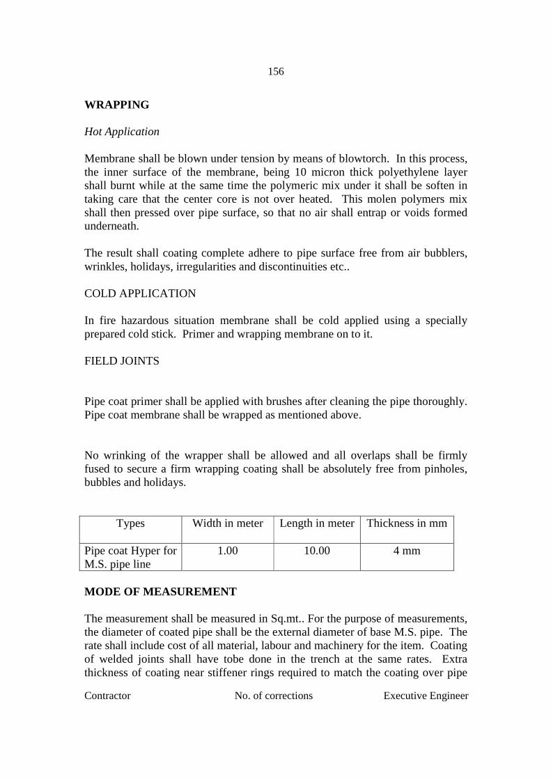
Contractor No. of corrections Executive Engineer
156
WRAPPING Hot Application Membrane shall be blown under tension by means of blowtorch. In this process, the inner surface of the membrane, being 10 micron thick polyethylene layer shall burnt while at the same time the polymeric mix under it shall be soften in taking care that the center core is not over heated. This molen polymers mix shall then pressed over pipe surface, so that no air shall entrap or voids formed underneath. The result shall coating complete adhere to pipe surface free from air bubblers, wrinkles, holidays, irregularities and discontinuities etc.. COLD APPLICATION In fire hazardous situation membrane shall be cold applied using a specially prepared cold stick. Primer and wrapping membrane on to it. FIELD JOINTS Pipe coat primer shall be applied with brushes after cleaning the pipe thoroughly. Pipe coat membrane shall be wrapped as mentioned above. No wrinking of the wrapper shall be allowed and all overlaps shall be firmly fused to secure a firm wrapping coating shall be absolutely free from pinholes, bubbles and holidays.
Types
Width in meter Length in meter Thickness in mm
Pipe coat Hyper for M.S. pipe line
1.00 10.00 4 mm
MODE OF MEASUREMENT The measurement shall be measured in Sq.mt.. For the purpose of measurements, the diameter of coated pipe shall be the external diameter of base M.S. pipe. The rate shall include cost of all material, labour and machinery for the item. Coating of welded joints shall have tobe done in the trench at the same rates. Extra thickness of coating near stiffener rings required to match the coating over pipe

Contractor No. of corrections Executive Engineer
157
shall and coating over the stiffener rings will not be paid extra and tendered rate shall be deemed to include cost of such extra required near stiffeners. Specifications mentioned in IS:10221 and AWWA C-203 shall be made applicable. MODE OF PAYMENT 90% after coating the pipes 5% after lowering, laying and jointing in trenches 5% after hydraulic testing of pipe line. ITEM NO. 23 REFILLING TRENCHES OF PIPE LINE In no case the contractor shall be allowed to refill the trenches in hard excavated portion by the boulders from the excavated stuff. This portion of trench shall be refilled by soft murum or soft strata from excavated stuff. No extra cost shall be paid. After the pipelines are laid, jointed and tested, the refilling of trenches with excavated stuff shall be done approximately in 20 to 30 cms. Higher than road or natural ground level, to allow for sinking afterwards. This refilling shall be done in 15 cms thick layers duly watering compacting, each layer. The 15 cms thick layer immediately in contract on or under pipe shall have no stones or chips, but only soil or soft murum selected from the excavated stuff after refilling. If it is sunk below the road level after some time completion of work, the Contractor shall have to make it goods at his cost.
Before lowering of all pipes in trenches a layer of murum selected from excavated stuff shall be provided below pipe line for proper grading and to act as cushion etc. Though the contractor is required to do refilling before hydraulic testing to avoid traffic hurdle, no payment for refilling of trenches of pipe line shall be payable till satisfactory hydraulic testing is given. Re-excavation required, if any, during testing shall be done by the contractor at his cost.

Contractor No. of corrections Executive Engineer
158
ITEM NO. 24 HYDRAULIC TESTING OF M.S. PIPE After the work of laying pipeline is completed and before it is commissioned, the pipeline shall be tested prior to painting in the field both for its strength and leakage in the following manner. Whether stated specifically elsewhere or not, the testing in section of 0.5 to 1 km shall have to be completed within 3 months of laying and jointing. Delay in testing will be subject to a fine at 5% of the cost of the testing item for delay of every month or part thereof. The pipeline laid length will be divided into sections specified by Engineer-in-Charge. The contractor shall recheck pipe and valves for cleanliness and shall recheck operations of the valves. The open ends of the pipeline or sections thereof shall normally be stopped off by blank flanges or cap ends additionally secured where necessary by temporary struts and wedges. All anchor and thrust blocks must have been completed and all pipe straps and other devices intended to prevent movement of pipe must have been securely fastened. The contractor shall clean out the whole pipeline and flush it with water, so as to remove dust, dirt and any foreign matter laying in the pipeline. No separate payment for the work of cleaning will be made and the rates under various items of work include thereof. Each valved section of the pipeline shall be subjected to hydraulic test in section. For this test, the pipe shall be slowly filled with clean water by opening cross connection with the existing mains or otherwise by pumping water into the line (water and pumping arrangement is to be arranged by contractor) as directed and all air shall be expelled from the pipeline through hydrants, air valves and blow off fixed on the pipeline. Once the pipe is full, the cross connection or pumping shall be closed. The pressure in the pipeline should then be raised in stages and built up and maintained by means of suitable approved pumps, to the specified test pressure based on the elevation of the lowest point on the line or section under test. The test pressure shall be not less than 15.00 kg/cm2 test pressure, or 1.5 times the working pressure, whichever is higher. Before starting the pressure test, the expansion joint shall be tightened the test pressure shall be maintained for at least 24 hours. The drop in pressure shall not exceed 0.7 kg/cm2 within a period of 2 hours after the full test pressure is built-up. Under this pressure no leak or sweating shall be visible at the welded joints. During the test, the pipe shall be struck sharp blows with 1.5 kg hammer.
Contractor No. of corrections Executive Engineer
159
Water shall not spout, ooze or sweat through any part. In case of any leak observed anywhere in the field joints whether welded or bolted, the same shall be repaired entirely at the contractor's cost which shall include repairs to welding and regunitting etc. The repaired joint shall be subjected to retest. No section shall be accepted unless it is perfectly water tight. The entire cost of testing, retesting including cost of water taken together shall be paid under relevant item or Bill of Quantities. The contractor shall make all the arrangements for all labour, pumps, pressure gauge equipment etc. The gauges should be got tested if insisted by the Engineer-in-Charge. The contractor shall arrange for labour required for operating air valves, scour valves etc. Any labour of Pradhikaran employed for the above activities of the test other than supervision shall charged to the contractor as per rules. The hydraulic testing of the water main will be carried out for entire length as directed by Engineer-in-Charge. If any leakages are observed even during defects liability period due to defective workmanship, the same shall be rectified immediately. The charges of repairs if done departmently will be recovered from the amount of retention money. Repairs on live water mains are to be carried out immediately to avoid wastage of water and other problems such as disruption of water supply and traffic etc. In view of this, it will be very difficult to give prior intimation to concerned contractor. As such the cost of repairs, being the expenditure will be recovered from the contractor's retention money withheld in deposit without giving any prior intimation. The contractor will not challenge or claim any extra for such action on the part of the Department. Generally the contractor shall be required to test the pipe line sections of 1 (One) Km using necessary equipment. However, if the Engineer-in-Charge directs, to test full pipeline lengths in further suitable sections in the interest of the work, the tenderers will have to carry out the test in such sections as directed by Engineer-in-Charge. MODE OF PAYMENT AND UNIT OF MEASUREMENT Even though hydraulic testing is carried out in sections of 0.5 to 1.0 Km the total length of hydraulically tested pipe line will be measured upto four decimals of Kilometers and will be paid under this item. No extra payment for hydraulic testing of gaps left in pipe line due to any reasons will be made.

Contractor No. of corrections Executive Engineer
160
ANNEXURE – 1
DETAILS OF RESPECTIVE AND APPROVED MAKES FOR MATERIALS TO BE USED
LATEST VERSION OF ISS SHALL BE REFERRED
No. Material ISS Code No. Approved Make 1 Tor Steel 1786 (Fe415) Approved manufacturers 2 MS round bar 432 (Part I & II) Approved manufacturers 3 Sluice valves 50 to
300 mm 780-1984 Makes approved by MJP
4 Butterfly valve 300 mm dia
13095:1991 Makes approved by MJP
5 Above 300 mm 2906 -1984 GNK Catelogue
Makes approved by MJP
6 Air valves IS:10845 (Latest Edition)
Makes approved by MJP
7 M.S. pipes IS:3589-2001 Approved by MJP
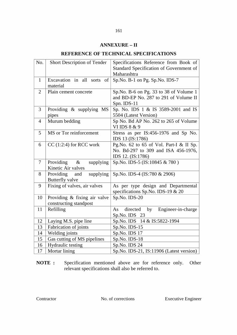
Contractor No. of corrections Executive Engineer
161
ANNEXURE – II
REFERENCE OF TECHNICAL SPECIFICATIONS
No. Short Description of Tender Specifications Reference from Book of Standard Specification of Government of Maharashtra
1 Excavation in all sorts of material
Sp.No. B-1 on Pg. Sp.No. IDS-7
2 Plain cement concrete Sp.No. B-6 on Pg. 33 to 38 of Volume 1 and BD-EP No. 287 to 291 of Volume II Spn. IDS-11
3 Providing & supplying MS pipes
Sp. No. IDS 1 & IS 3589-2001 and IS 5504 (Latest Version)
4 Murum bedding Sp No. Bd AP No. 262 to 265 of Volume VI IDS 8 & 9
5 MS or Tor reinforcement Stress as per IS:456-1976 and Sp No. IDS 13 (IS:1786)
6 CC (1:2:4) for RCC work Pg.No. 62 to 65 of Vol. Part-I & II Sp. No. Bd-297 to 309 and ISA 456-1976, IDS 12. (IS:1786)
7 Providing & supplying Kinetic Air valves
Sp.No. IDS-5 (IS:10845 & 780 )
8 Providing and supplying Butterfly valve
Sp.No. IDS-4 (IS:780 & 2906)
9 Fixing of valves, air valves As per type design and Departmental specifications Sp.No. IDS-19 & 20
10 Providing & fixing air valve constructing standpost
Sp.No. IDS-20
11 Refilling As directed by Engineer-in-charge Sp.No. IDS 23
12 Laying M.S. pipe line Sp.No. IDS 14 & IS:5822-1994 13 Fabrication of joints Sp.No. IDS-15 14 Welding joints Sp.No. IDS 17 15 Gas cutting of MS pipelines Sp.No. IDS-18 16 Hydraulic testing Sp.No. IDS 24 17 Mortar lining Sp.No. IDS-21, IS:11906 (Latest version) NOTE : Specification mentioned above are for reference only. Other
relevant specifications shall also be referred to.

Contractor No. of corrections Executive Engineer
162
MAHARASHTRA JEEVAN PRADHIKARAN
MAHARASHTRA JEEVAN PRADHIKARAN
URBAN & RURAL SCHEME CIRCLE, THANE
MAHARASHTRA JEEVAN PRADHIKARAN URBAN & RURAL SCHEME DIVISION VIRAR
Name of work :. Shifting of M.S. Pipe line of 790 mm dia, 6.4 mm thick
obstructing road widening from Walive Phata to Gokhivare Phata Vasai.
DECLARATION I/We Guarantee that I/We hereby declare that I/We have made myself/ourselves thoroughly
conversant with the local conditions regarding all materials such as stones,
murum sand availability of water etc. and labor on which, I/We have based our
rates from this work. The specifications and requirements for this work have
been carefully studied and understood by me/us before submitting the tender. I
have visited the site of work and fully acquainted myself with the local site
conditions and quoting my offer accordingly.
I/We undertake to use only the best materials, to be approved by the Executive
Engineer in-charge of the work or his duly authorised representative before
starting the work and also to abide by this decision.
I/We hereby undertake to pay the labour engaged on the work as per minimum
wages Act 1984 applicable to the zone concerned or any other as applicable.
Contractor Seal
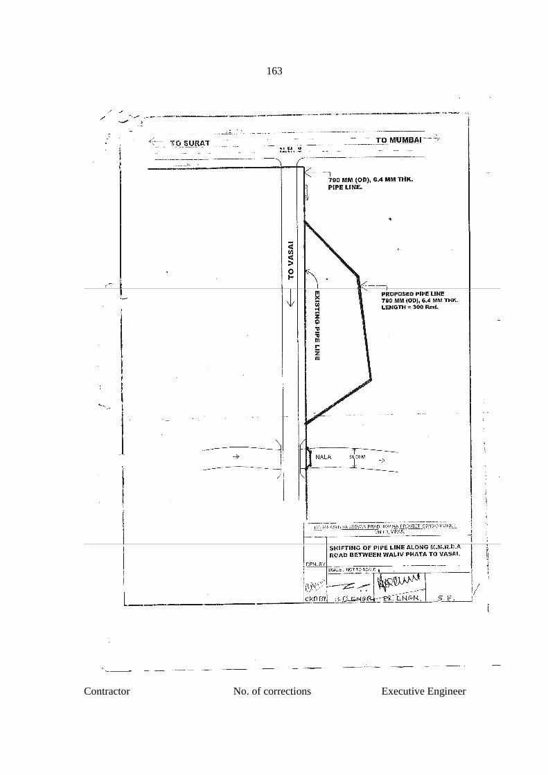
Contractor No. of corrections Executive Engineer
163