magnus hedlund *, tobias kamf, juan de santiago, johan ...1083426/fulltext01.pdf · energies...
TRANSCRIPT

energies
Article
Reluctance Machine for a Hollow Cylinder Flywheel
Magnus Hedlund *, Tobias Kamf, Juan de Santiago, Johan Abrahamsson and Hans Bernhoff
Division for Electricity, Uppsala University, Lägerhyddsvägen 1, 75237 Uppsala, Sweden;[email protected] (T.K.); [email protected] (J.d.S.);[email protected] (J.A.); [email protected] (H.B.)* Correspondence: [email protected]; Tel.: +46-18-471-5804
Academic Editor: K.T. ChauReceived: 28 October 2016; Accepted: 28 February 2017; Published: 7 March 2017
Abstract: A hollow cylinder flywheel rotor with a novel outer rotor switched reluctance machine(SRM) mounted on the interior rim is presented, with measurements, numerical analysis andanalytical models. Practical experiences from the construction process are also discussed.The flywheel rotor does not have a shaft and spokes and is predicted to store 181 Wh/kg at ultimatetensile strength (UTS) according to simulations. The novel SRM is an axial flux machine, chosen dueto its robustness and tolerance for high strain. The computed maximum tip speed of the motor atUTS is 1050 m/s. A small-scale proof-of-concept electric machine prototype has been constructed,and the machine inductance has been estimated from measurements of voltage and current andcompared against results from analytical models and finite element analysis (FEA). The prototypemeasurements were used to simulate operation during maximal speed for a comparison towardsother high-speed electric machines, in terms of tip speed and power. The mechanical design of theflywheel was performed with an analytical formulation assuming planar stress in concentric shells oforthotropic (unidirectionally circumferentially wound) carbon composites. The analytical approachwas verified with 3D FEA in terms of stress and strain.
Keywords: flywheel energy storage (FES); hollow cylinder flywheel; reluctance machine; high-speedmachines
1. Introduction
A new era of high-speed flywheel energy storage (FES) started with the advent of carboncomposite flywheels, a technology that has become more viable due to a trend of decreasing costs ofpower electronics, position sensors (for magnetic bearings) and microprocessors [1]. The commercialpotential for FES systems has recently gained attention in various applications. In racing sports, anFES powered the winning car of the legendary Le Mans race for several years. Flywheels have beenmounted on inner city hybrid buses to increase fuel efficiency. The technology has also been proven toenable the use of intermittent renewable energy sources, for example by stabilizing the electric grid atremote wind farms, allowing for better utilization of transmission lines. Improving the capacity factorof power lines is important in all applications when the cost of the transmission itself is a significantcost of the installation, such as for offshore wind power or wave power parks. FESs are used to providefast regulation power for maintaining the grid frequency, decreasing the use of inefficient coal plantswith low ramp rates for the task. On a distribution grid and end customer level, FESs are used toimprove power quality for industries and data centers [1].
Modern, electrified flywheels are mainly composed of steel, aluminum, titanium, carbon and glassfiber composites, which are all readily available in bulk volumes. Energy is stored when the electricmotor/generator accelerates the flywheel, and energy is released when the electric machine acts asa generator and slows down the flywheel. Flywheels compete with storage technologies, such as
Energies 2017, 10, 316; doi:10.3390/en10030316 www.mdpi.com/journal/energies

Energies 2017, 10, 316 2 of 18
batteries and electrolytically double-layered capacitors (EDLCs, popularly known as supercapacitors)in applications that require a large number of charge-discharge cycles with high specific power.Flywheels excel when compared against batteries in terms of specific power and cycling fatigue.Comparing costs is harder however, since the latter is mass-produced, but the former is not. An estimatecan be computed based on the knowledge that for rotating electrical machines, raw materials compriseabout 60%–70% of the cost [2]. GKN Hybrid Power (Worcestershire, UK) reported that the raw materialcost of a standard internal combustion engine is about 685 USD, compared to their 30 kW/111 Whflywheel for automotive applications, which costs about 723 USD [3]. The resulting cost would then beabout 1100 USD, or 10,000 USD/kWh, which is about 30-times more expensive than Li-ion batteries [4].On the other side, a high-performance Li-ion battery can only use 3% of its capacity to withstand106 charge-discharge cycles (which FESs and EDLCs are typically rated for), during moderate dischargerates (≤1C) [5]. It should also be noted, however, that a flywheel excels at delivering power whileretaining a good cycle life. A battery topology with a system specific energy of 200 Wh/kg (includingcooling system, etc.) with a weight of 0.6 kg would match the GKN flywheel (in terms of energycapacity) mentioned above, not taking into account cycling properties. Assuming a requirement of106 cycles, the battery system weight would be increased to 20 kg, and with a discharge rate of 1C,the maximum power is then only 4 kW. To meet the power requirements combined with cyclingproperties, the system weight would have to be increased to 150 kg, which is 10-times heavier thana modern flywheel system [1]. Li-ion batteries can be and are currently used in F1 racing at higherpower levels, but the battery life becomes very limited.
The specific energy of state-of-the-art automotive FESs (GKN Hybrid Porsche GT3R Flywheel [6])is 2.7-times larger than state-of-the-art automotive EDLCs (Maxwell 125V Heavy TransportationModule [7]), while retaining a specific power 1.8-times larger [1]. However, FESs are consideredto be systems of high complexity, when compared to batteries and supercapacitors. Increasing thespecific energy of FESs is important since more end applications become feasible technically andviable economically.
Optimizing Specific Energy
The specific energy e grows quadratically with radius r from a fixed rotational axis, as can be seenby inspecting the kinetic energy E in a rotating body per unit mass m (with a rotational velocity of ω):
e =Em
=Jω2
2m=
ω2
2m
∫r2dm, (1)
where the moment of inertia around a fixed axis J is expanded into its integral definition. The formulaessentially states the three ways to optimize for specific energy:
• Increase rotational speed;• Decrease mass;• Distribute mass closer to the rim.
The advent of carbon composites has greatly progressed flywheel development in terms of thefirst two bullet points above. This paper aims to provide progress in the field with regards to the thirdoption by examining an electric machine with properties suitable for hollow cylinder flywheels.
The paper is divided into three parts: Firstly, hollow cylinder flywheels are introduced, anda theoretical rotor design is presented. Secondly, a switched reluctance machine (SRM) for theaforementioned rotor is presented with measurements and simulations. Thirdly, simulations based onthe above measurements are used to compare the SRM with other high-speed machines.
2. Integrated Hollow Flywheels
The connection of a composite flywheel rim to a shaft is an issue well addressed in the technicalliterature [8–24]. The most common class of solutions can be denoted strain-matching and can be
Energies 2017, 10, 316 3 of 18
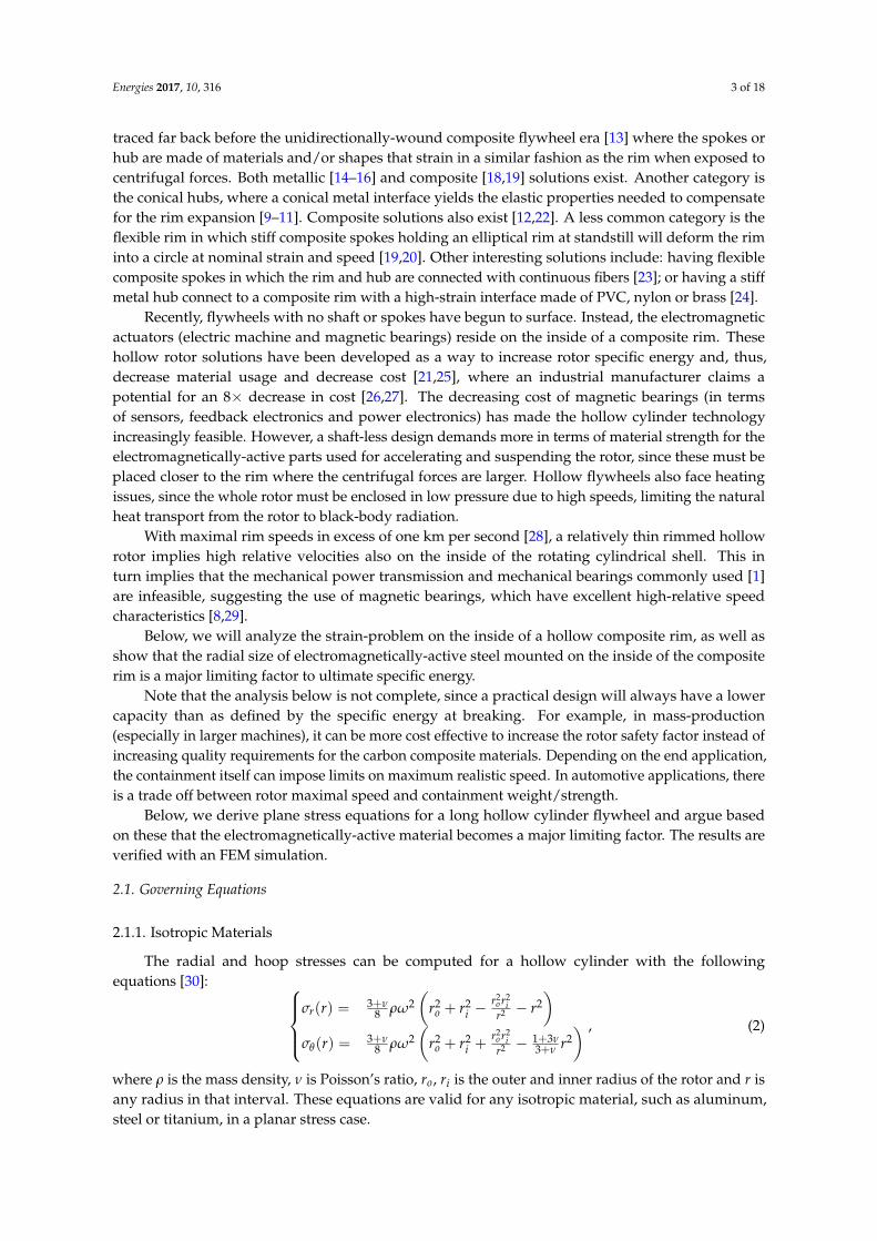
traced far back before the unidirectionally-wound composite flywheel era [13] where the spokes orhub are made of materials and/or shapes that strain in a similar fashion as the rim when exposed tocentrifugal forces. Both metallic [14–16] and composite [18,19] solutions exist. Another category isthe conical hubs, where a conical metal interface yields the elastic properties needed to compensatefor the rim expansion [9–11]. Composite solutions also exist [12,22]. A less common category is theflexible rim in which stiff composite spokes holding an elliptical rim at standstill will deform the riminto a circle at nominal strain and speed [19,20]. Other interesting solutions include: having flexiblecomposite spokes in which the rim and hub are connected with continuous fibers [23]; or having a stiffmetal hub connect to a composite rim with a high-strain interface made of PVC, nylon or brass [24].
Recently, flywheels with no shaft or spokes have begun to surface. Instead, the electromagneticactuators (electric machine and magnetic bearings) reside on the inside of a composite rim. Thesehollow rotor solutions have been developed as a way to increase rotor specific energy and, thus,decrease material usage and decrease cost [21,25], where an industrial manufacturer claims apotential for an 8× decrease in cost [26,27]. The decreasing cost of magnetic bearings (in termsof sensors, feedback electronics and power electronics) has made the hollow cylinder technologyincreasingly feasible. However, a shaft-less design demands more in terms of material strength for theelectromagnetically-active parts used for accelerating and suspending the rotor, since these must beplaced closer to the rim where the centrifugal forces are larger. Hollow flywheels also face heatingissues, since the whole rotor must be enclosed in low pressure due to high speeds, limiting the naturalheat transport from the rotor to black-body radiation.
With maximal rim speeds in excess of one km per second [28], a relatively thin rimmed hollowrotor implies high relative velocities also on the inside of the rotating cylindrical shell. This inturn implies that the mechanical power transmission and mechanical bearings commonly used [1]are infeasible, suggesting the use of magnetic bearings, which have excellent high-relative speedcharacteristics [8,29].
Below, we will analyze the strain-problem on the inside of a hollow composite rim, as well asshow that the radial size of electromagnetically-active steel mounted on the inside of the compositerim is a major limiting factor to ultimate specific energy.
Note that the analysis below is not complete, since a practical design will always have a lowercapacity than as defined by the specific energy at breaking. For example, in mass-production(especially in larger machines), it can be more cost effective to increase the rotor safety factor instead ofincreasing quality requirements for the carbon composite materials. Depending on the end application,the containment itself can impose limits on maximum realistic speed. In automotive applications, thereis a trade off between rotor maximal speed and containment weight/strength.
Below, we derive plane stress equations for a long hollow cylinder flywheel and argue basedon these that the electromagnetically-active material becomes a major limiting factor. The results areverified with an FEM simulation.
2.1. Governing Equations
2.1.1. Isotropic Materials
The radial and hoop stresses can be computed for a hollow cylinder with the followingequations [30]:
σr(r) = 3+ν8 ρω2
(r2
o + r2i −
r2o r2
ir2 − r2
)σθ(r) = 3+ν
8 ρω2(
r2o + r2
i +r2
o r2i
r2 − 1+3ν3+ν r2
) , (2)
where ρ is the mass density, ν is Poisson’s ratio, ro, ri is the outer and inner radius of the rotor and r isany radius in that interval. These equations are valid for any isotropic material, such as aluminum,steel or titanium, in a planar stress case.
Energies 2017, 10, 316 4 of 18
2.1.2. Transversely Isotropic Materials
Unidirectionally wound carbon fiber composites exhibit anisotropic material properties, whichcan be modeled as a transversely isotropic material in the rz-plane in a cylindrical coordinate system.
The corresponding stress equations can be seen below [8,31]:σr = C1r−1−µ + C2r−1+µ + ρω2r2
µ2−9 (3 + β)
σθ = C1µr−1−µ + C2µr−1+µ + ρω2r2
µ2−9 (3β + µ2), (3)
where:
C1 =K(r3
i rµo − rµ
i r3o) + Pir
µo ri − Porµ
i ro
r2µi − r2µ
o(riro)
µ, (4)
C2 =K(rµ+3
o − rµ+3i ) + Porµ+1
o − Pirµ+1i
r2µi − r2µ
o, (5)
and:
K =ρω2
µ2 − 9(3 + β), (6)
µ2 =Eθ
Er
1− νzrνrz
1− νzθνθz, (7)
β = νθz1 + νzr
1− νzθνθz, (8)
where E is the elastic modulus and P is the pressure on the inner and outer surfaces. For a singlehollow shell, P is zero. In a situation where several shells are shrink-fitted onto each other (as discussedbelow), there are interface pressures in between these shells. Then, for two subsequent shells m,n,the following boundary condition applies:
Po,m = Pi,n, (9)
together with a zero-interference constraint.The stress equations can then be solved with numerical methods. For a multi-shell situation,
a system of equations is formed. These equations have been shown to work well for quickly solving forstress [31], allowing for iterative testing of different designs. The equations can be used to approximatestress for segmented inner shells by assuming a low Eθ . The final design is then verified in terms ofboth stress and strain in 3D FEA software.
2.2. Practical Considerations
The carbon fibers are unidirectionally tangentially wound within an epoxy matrix to attainmaximal hoop tensile strength. The strength in radial and axial directions is dependent on the epoxymatrix, which is orders of magnitude weaker than the fibers. To alleviate radial stress limitations,several thin composite shells are shrink-fitted onto each other. The shrink-fit process (and also thematrix curing process) limits how much interface pressure can be attained between shells, whichin turn limits the maximal speed [31]. To account for this in the design below, thermal expansionlimitations were accounted for when computing interference pressure.
2.3. Mechanical Simulation Results
A hollow cylinder flywheel rotor design was found by iteratively solving the equations presentedabove for a multi-shell system. The final solution was then verified within the FEA software Solidworks,and the corresponding stresses and strains can be seen in Figure 1a. For the analytical equations,the steel was simulated as segmented by assuming a low Eθ (similar in approach to [31]), and in FEA,

Energies 2017, 10, 316 5 of 18
it was done by simulating a 5◦ segment, as seen in Figure 1c. The rotor is composed of four shells.The innermost shell was constructed of laminated spring steel sheet metal with a stack thickness of5.5 mm, and the three outer shells are Toray T1000G (Toray CFA, Flower Mound, TX, USA)/epoxycomposite material, with a total thickness of 10 cm. The ultimate specific energy for this design is181 Wh/kg, at a rim speed of 1260 m/s, with the composite pushed close to its theoretical limits [32].This value can be compared to 195 Wh/kg, the highest ultimate specific energy flywheel rotor knownto date [28], although that rotor had no electric machine (in contrast to this one). The hoop stress in thecomposite is increased due to the weight of the slit steel, which provides no hoop strength on its own.This sets an upper limit for steel thickness if optimizing for specific energy in a hollow rotor. On theother hand, the centrifugal forces within the composite rims increase with radius, causing tensile stressto build up, which can lead to delamination. Since the radial strength is much lower than the hoopstrength for unidirectionally-wound composites, having steel on the inside can help keep the radialstress compressive (similar to [31]). The composite shells were press fitted. Friction forces betweenconsecutive shells were assumed to be zero. It is thus seen that high specific energy can be attained inhollow steel/carbon composite rotors, but that steel thickness is an important parameter.
500 550 600
0
0.5
1
1.5
2
2.5
3
Radius [mm]
Stress[G
Pa]
Full speedStandstillHoopRadial
500 550 600
−1.5
−1
−0.5
0
0.5
1
1.5
2
Radius [mm]
Strain[%
]
Full speedStandstillHoopRadial
(a)
(b)
−5000
500
−500
0500
0
500
1,000
x-coordinate [mm]y-coordinate [mm]
z-coordinate[m
m]
0
1
2Hoop
stress
[GPa]
(c)
Figure 1. (a) Stress and strain of proposed design, from the FEA solution. The radial dimensions of theflywheel are illustrated at the bottom. The hatch pattern corresponds to composite material. The dottedpattern is steel. The materials are close to their respective stress and strain-limits; (b) concept drawingof rotor (not to scale). Note the lines in the innermost layer, representing slits in the steel; and (c) FEAsolution of the hoop stress distribution inside the hollow cylinder. The simulated 5◦ segment is shown.
Energies 2017, 10, 316 6 of 18
Note that carbon composites can expand well in excess of 1.0%, far surpassing the strain limit ofmagnetic materials, as listed in Table 1. Most materials cannot even sustain the fatigue limit of theunidirectional composite material, which for epoxy matrices is 0.6% [33]. Any material mounted on theinside of a hollow cylinder will be pressed by centrifugal forces against an expanding composite shell.
Table 1. Material data on materials [34]. Note that the last column assumes linear elasticity, which is anapproximation close to Ultimate Tensile Strength (UTS).
Material UTS (MPa) Elastic Modulus (GPa) εmax (%)
Hard Ferrite 50 170 0.03AlNiCo 50 150 0.03
NeDyFeB 75 160 0.05SmCo 35 150 0.02
Steel E470 650 210 0.31Sandvik Safeni 52 Steel 950 200 0.47
Stahlbecker Spring Steel 1.1274 2000 206 0.97Copper 210 128 0.16
Aluminum 7075-T6 572 71 0.80
This problem can be alleviated by placing the materials on low-friction sleds [31]. Furthermore,a low-modulus plastic matrix can be put between sensitive materials to keep the effects from centrifugalforces compressive. The cycling fatigue behavior is not investigated, but could pose a problem.Another alternative is to infuse epoxy with magnetic materials, in exchange for a decrease of materialfunctionality (a relative permeability µr = 13) [1]. Further, there has been some attempts at makingflexible magnets [27,35]. In this paper, a reluctance machine solution is proposed, since these can bemade from strong steel, which is tolerant to straining and bending.
3. Switched Reluctance Machine
The SRM is considered a mechanically robust and relatively efficient topology, and its marketpenetration is increasing [36]. The SRM has been considered for flywheel energy storage, for examplein grid stabilization [37,38], in islanding operation [39] and power smoothing [40]. An SRM can bebuilt with only µ-metals, and the lack of exotic permanent magnet material makes them robust, faulttolerant and capable of high temperature operation while still achieving high torque [41].
Many different topologies with different characteristics are found in the literature. Especiallyrelevant for the hollow cylinders presented above are the external rotor variants [42]. C-core statorshave been proposed to simplify the winding process, allowing for simpler manufacturing processes [43].Although reduced torque ripple is not important for the flywheel rotor itself (since these generallyhave a high moment of inertia), secondary benefits include decreased losses, decreased vibration andmore constant charging and discharging rates. The characteristic ripple torque of axial flux SRMs hasbeen a subject under study [44–46].
Based on the results in the literature, we propose an axial flux outer rotor machine for the hollowcylinder flywheel application, in an effort to avoid salient features and a long flux path in the backyoke. This is since the thickness of the steel layer on the inside of the flywheel was seen to be a majorlimiting factor above. The electric machine has c-core stators and two axial air gaps, similar to [47], butwith an inner stator and fewer rotor poles.
3.1. Machine Topology
A 3D schematic view of the proposed axial flux switched reluctance machine is shown in Figure 2.The orange windings (seen in the figure) can be magnetized, driving an axial magnetic field in the stator,drawn in blue. At the top and bottom of the stator, the field flows radially, and then axially, into the airgap. The rotor (drawn in red) flux is axial. Note that the machine laminations are not stacked in thesame plane, although all electrical steel can be magnetized in a unipolar fashion. The rotor presented

Energies 2017, 10, 316 7 of 18
in the schematic drawing consists of one pole of laminated (in the rϕ-plane) steel spanning 180◦ anda counterweight made of non-ferromagnetic stainless steel placed on the opposite side (not drawn).Note that more poles can be added in the circumferential direction, to change the torque/electricalfrequency ratio. The stator is laminated in the rz-plane and divided into three phases spaced 120◦ apart,allowing for more constant torque. The rotor can also be separated axially to increase torque (while alsoincreasing reluctance due to a larger effective air gap). The schematic drawing above contains two axialpoles and, thus, four axial air gaps. A 3-1-2 (# of poles for the stator, circumferential rotors and axialrotors, respectively) topology as seen in Figure 2 has the minimum amount of circumferential poles.
Rotor axial segmentsStator axial segments
WindingsFlux path in airgap
Figure 2. Schematic view of the proposed axial flux machine. The stator is drawn in blue, with orangewindings, and the rotor is drawn in red. Only electromagnetically-active material is included in thepicture. The concept drawing has three stator poles with separate winding phases and one 180◦ rotorpole. The rotor is split into two axial segments. The magnetic flux lines in the air gap are drawnin green.
There are a number of qualitative properties of this topology of interest: Since the air gap is axial,radial expansion during full speed will not affect the magnetic field path. The radial forces in a radialflux machine can be considerable and can affect the rotor fatigue characteristics with respect to cyclicloading. The proposed design has a weak stabilizing force in the radial direction. However, the rotorexperiences axial negative stiffness around the air gap. This electric machine topology is intendedto be mounted on a hollow flywheel with a set of separate magnetic bearings (which are needed tohandle the high relative velocities on the inside of the rim). The axial negative stiffness from the electricmachine must then be negated by axial magnetic bearings.
Losses
The high speeds of flywheel rotors require operation in a vacuum to reduce the effects of turbulentdrag losses [48]. With no convection or conductive heat transfer, it is hard to transport excess heataway. Black-body radiation is then one of the few mechanisms removing excess heat.
With higher rotational speeds, the frequency dependent losses become increasingly important.Both the rotor and stator can be operated with unipolar magnetization, decreasing the HB-curve areaand, in turn, reducing losses. The unipolar control strategy has been previously shown to decreaselosses for switched reluctance machines [49].
Since the electric machine can be completely demagnetized, the standby losses can be kept low,decreasing the flywheel spin down rate.
The proposed geometry inherently has plateaus where dLdθ = 0 during a revolution and in turn, no
back-emf, which decreases reactive power requirements on the power electronics [50].
Energies 2017, 10, 316 8 of 18
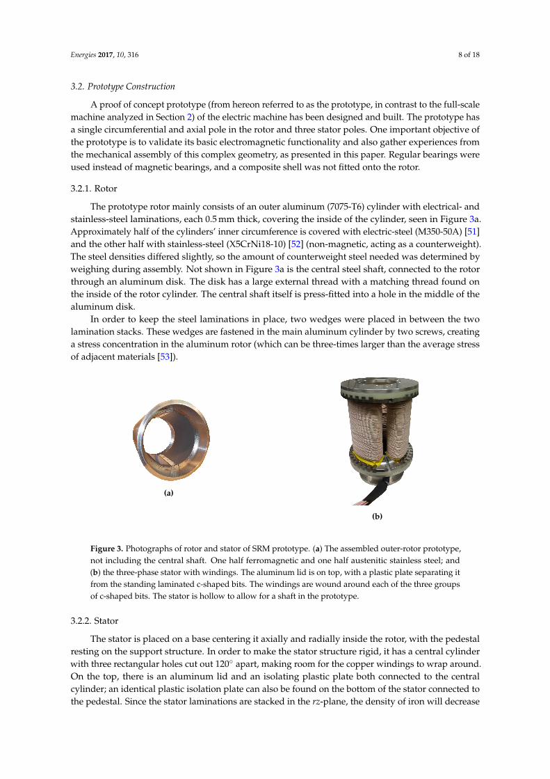
3.2. Prototype Construction
A proof of concept prototype (from hereon referred to as the prototype, in contrast to the full-scalemachine analyzed in Section 2) of the electric machine has been designed and built. The prototype hasa single circumferential and axial pole in the rotor and three stator poles. One important objective ofthe prototype is to validate its basic electromagnetic functionality and also gather experiences fromthe mechanical assembly of this complex geometry, as presented in this paper. Regular bearings wereused instead of magnetic bearings, and a composite shell was not fitted onto the rotor.
3.2.1. Rotor
The prototype rotor mainly consists of an outer aluminum (7075-T6) cylinder with electrical- andstainless-steel laminations, each 0.5 mm thick, covering the inside of the cylinder, seen in Figure 3a.Approximately half of the cylinders’ inner circumference is covered with electric-steel (M350-50A) [51]and the other half with stainless-steel (X5CrNi18-10) [52] (non-magnetic, acting as a counterweight).The steel densities differed slightly, so the amount of counterweight steel needed was determined byweighing during assembly. Not shown in Figure 3a is the central steel shaft, connected to the rotorthrough an aluminum disk. The disk has a large external thread with a matching thread found onthe inside of the rotor cylinder. The central shaft itself is press-fitted into a hole in the middle of thealuminum disk.
In order to keep the steel laminations in place, two wedges were placed in between the twolamination stacks. These wedges are fastened in the main aluminum cylinder by two screws, creatinga stress concentration in the aluminum rotor (which can be three-times larger than the average stressof adjacent materials [53]).
(a)
(b)
Figure 3. Photographs of rotor and stator of SRM prototype. (a) The assembled outer-rotor prototype,not including the central shaft. One half ferromagnetic and one half austenitic stainless steel; and(b) the three-phase stator with windings. The aluminum lid is on top, with a plastic plate separating itfrom the standing laminated c-shaped bits. The windings are wound around each of the three groupsof c-shaped bits. The stator is hollow to allow for a shaft in the prototype.
3.2.2. Stator
The stator is placed on a base centering it axially and radially inside the rotor, with the pedestalresting on the support structure. In order to make the stator structure rigid, it has a central cylinderwith three rectangular holes cut out 120◦ apart, making room for the copper windings to wrap around.On the top, there is an aluminum lid and an isolating plastic plate both connected to the centralcylinder; an identical plastic isolation plate can also be found on the bottom of the stator connected tothe pedestal. Since the stator laminations are stacked in the rz-plane, the density of iron will decrease
Energies 2017, 10, 316 9 of 18
with radius. To alleviate this, the lamination stacks are separated with small ferromagnetic wedges.These wedges help to keep the lamination stacks in place, but come with the drawback of increasededdy-current losses, as they are not laminated. Two larger ferromagnetic wedges are placed to decreasethe dead-angle in between each phase, allowing the machine to produce a more constant torquewhile providing space for the copper windings to wrap around. Both of these wedges can be seenin Figure 3b alongside the outer radius where the base meets the stator. Also seen in Figure 3b arethe three stator windings along the length of the stator, one around each stator segment. The maindimensions are presented in Table 2.
Table 2. Dimensions of the prototype.
Parameter Value
Rotor outer radius, b 89 mmRotor inner radius, a 84 mm
Rotor height, h 148 mmAir gap, du,l 1 mm
Stator inner radius, e 60 mmStator outer radius, f 87 mm
Winding turns/phase, N 120# of phases 3
3.2.3. Support Structure
The support structure keeps the rotor and stator in place while allowing for easy access to theinterior of the machine. The structure consists of six steel square pipes linking two large aluminumplates together. In the center of each plate is a central hole where the bearing housings reside.The bearings used here are SKF self-aligning ball bearings (SKF, Göteborg, Sweden) that allow for aslight misalignment of the central axis without affecting the performance of the bearings, reducing thetolerances needed, reducing manufacturing costs and simplifying assembly.
3.3. Machine Parameters
3.3.1. Analytical Model
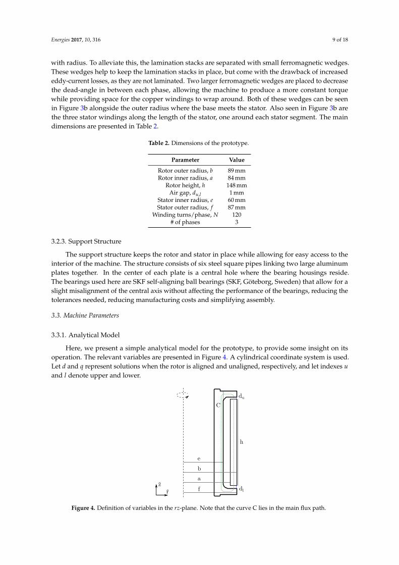
Here, we present a simple analytical model for the prototype, to provide some insight on itsoperation. The relevant variables are presented in Figure 4. A cylindrical coordinate system is used.Let d and q represent solutions when the rotor is aligned and unaligned, respectively, and let indexes uand l denote upper and lower.
du
dl
h
a
b
fr
z
^
C
e
Figure 4. Definition of variables in the rz-plane. Note that the curve C lies in the main flux path.
Energies 2017, 10, 316 10 of 18
Begin by considering Ampere’s law around curve C, as drawn in Figure 4. Assume the magneticfield is constant along the path of integration and that the steel is linear, isotropic, homogeneous andof high relative permeability. Then:
∮C
H · ds = NI ⇒
Bd = µ0 NIdu+dl
Bq = µ0 NIdu+h+dl
, (10)
where B is the magnetic flux density, N is the number of winding-turns and I is the winding current.The system energy is thus (assume that the q-axis field spreads out uniformly between the
protruding stator ends):
U =∫ B2
2µ0dV =
µ0
2N2 I2
(Vd + Viron
(du + dl)2 +
Vq + Viron
(du + h + dl)2
), (11)
where Vd,q and Viron is the volume occupied by a magnetic field in the air gap. The last two factorsaccount for radial and angular displacement,Vd = (du + dl)π
(b2 − a2) (1− |ρ|
b−a
)( 2π3 −θ2π
)Vq = (du + h + dl)π( f 2 − e2)1
(θ
2π
) , (12)
where r ∈ [a− b, b− a] and θ ∈ [0, 2π/3]. The gradient of the degrees of freedom (r and θ) yields theforce and torque on the rotor:Fr = − ∂U
∂ρ = µ04 N2 I2 (b+a)( 2π
3 −θ)du+dl
|ρ|ρ
τθ = − ∂U∂θ = µ0
4 N2 I2(
b2−a2
du+dl
(1− |ρ|
b−a
)− f 2−e2
du+h+dl
) , (13)
The axial force cannot be derived under the assumption of straight field lines. However, there willbe negative stiffness around the point when du = dl . That point is an unstable equilibrium. To properlybalance this force, we suggest magnetic bearings. The force equations also suggest that the radialposition is in a stable equilibrium with positive stiffness around perfect radial alignment (the argumentfor radial stiffness is overly simplified, but there will be a radially stabilizing force regardless).
The inductance (when radially and axially aligned) can be computed as (where A is area and Φmagnetic flux):
L =NΦ
I=
NI(Φd + Φq
)=
NI(
Bd Ad + Bq Aq)
, (14)
which:
=⇒
Ld = µ0N2 π3
b2−a2
du+dl
Lq = µ0N2 π3
f 2−e2
du+h+dl
. (15)
3.3.2. Finite Element Analysis
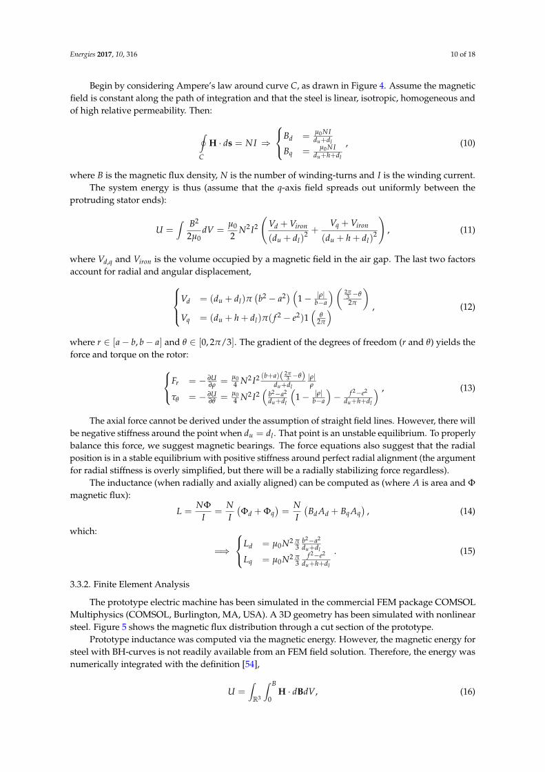
The prototype electric machine has been simulated in the commercial FEM package COMSOLMultiphysics (COMSOL, Burlington, MA, USA). A 3D geometry has been simulated with nonlinearsteel. Figure 5 shows the magnetic flux distribution through a cut section of the prototype.
Prototype inductance was computed via the magnetic energy. However, the magnetic energy forsteel with BH-curves is not readily available from an FEM field solution. Therefore, the energy wasnumerically integrated with the definition [54],
U =∫R3
∫ B
0H · dBdV, (16)
Energies 2017, 10, 316 11 of 18
Simulations were performed with the magnetizing current I stepped from 0 to 20 A in steps of1 A, and the solutions for the B and H-fields, as well as the volume elements for each mesh point wereextracted. These were numerically integrated to attain the inductance of the motor from a simulationwith nonlinear steel. The inductance for nonlinear steel was computed at 5 A.
1.2
1.0
0.6
0.8
0.4
0.2
Figure 5. FEM solution of the magnetic flux density at 18 A, for the prototype.
3.3.3. Experimental Inductance Measurement
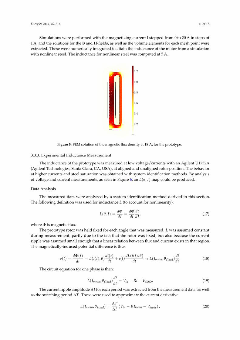
The inductance of the prototype was measured at low voltage/currents with an Agilent U1732A(Agilent Technologies, Santa Clara, CA, USA), at aligned and unaligned rotor position. The behaviorat higher currents and steel saturation was obtained with system identification methods. By analysisof voltage and current measurements, as seen in Figure 6, an L(θ, I) map could be produced.
Data Analysis
The measured data were analyzed by a system identification method derived in this section.The following definition was used for inductance L (to account for nonlinearity):
L(θ, I) =dΦdI
=dΦdt
dtdI
, (17)
where Φ is magnetic flux.The prototype rotor was held fixed for each angle that was measured. L was assumed constant
during measurement, partly due to the fact that the rotor was fixed, but also because the currentripple was assumed small enough that a linear relation between flux and current exists in that region.The magnetically-induced potential difference is thus:
v(t) =dΦ(t)
dt= L(i(t), θ)
di(t)dt
+ i(t)dL(i(t), θ)
dt≈ L(Imean, θ f ixed)
didt
. (18)
The circuit equation for one phase is then:
L(Imean, θ f ixed)didt
= Vin − Ri−Vdiode, (19)
The current ripple amplitude ∆I for each period was extracted from the measurement data, as wellas the switching period ∆T. These were used to approximate the current derivative:
L(Imean, θ f ixed) =∆T∆I
(Vin − RImean −Vdiode) , (20)
Energies 2017, 10, 316 12 of 18
Equation (20) can be applied to every pair of points in a large dataset of measurements, and theinductance at each point is then computed with a least squares method.
When dIdt 6= 0, eddy currents are induced that affect the measurements, which is a source of error
with this technique.
Measurement Equipment
Current was measured with a Hall effect sensor (LEM LA 55-P, LEM, Zürich, Switzerland) with abandwidth of 200 kHz [55]. Voltage was also measured via the Hall effect (LEM LV 25-P), with a 90%step response time of 40 µs [56].
The measurement signal was converted to a noise-resistant current signal and fed from thetransducers to a 10-bit ADC-unit. Each ADC-conversion took 4 µs, with a 120 ppm accuracy at abandwidth of 370 kHz [57]. The analog input aliasing filter was bypassed due to a low noise levelduring testing, as seen in Figure 6.
0 0.2 0.4 0.6 0.8 1
Time [ms]
2.2
2.3
2.4
2.5
Current [A]
Figure 6. The 100 kHz unfiltered current measurement used for estimating the saturation behavior ofthe prototype electric machine.
The switching frequency of the current controller was lowered to 2 kHz (from 20 kHz) for themeasurements to increase signal amplitude and increase data point density on the rising and decreasingslopes, as seen in Figure 6. The sample rate was 100 kHz. The current and voltage waveform measuredin the winding was fed asynchronously through a high-speed first-in-first-out (FIFO) buffer from themeasurement FPGA to a measurement data server for analysis.
A separate H-bridge was used to control the current, as seen in Figure 7. The current controller andsampling were done by a CompactRIO programmable automation controller (National Instruments,Austin, TX, USA). The custom circuit boards mounted on the CompactRIO were used to convertcurrent signals into voltage signals.
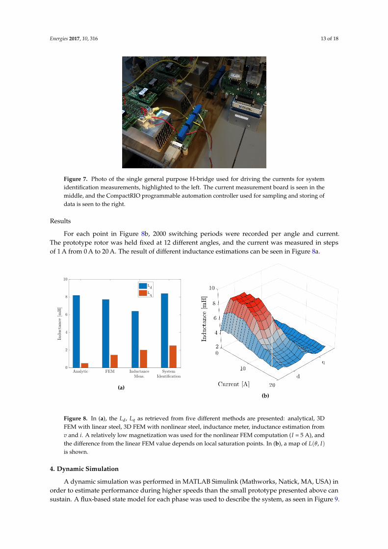
Energies 2017, 10, 316 13 of 18
Figure 7. Photo of the single general purpose H-bridge used for driving the currents for systemidentification measurements, highlighted to the left. The current measurement board is seen in themiddle, and the CompactRIO programmable automation controller used for sampling and storing ofdata is seen to the right.
Results
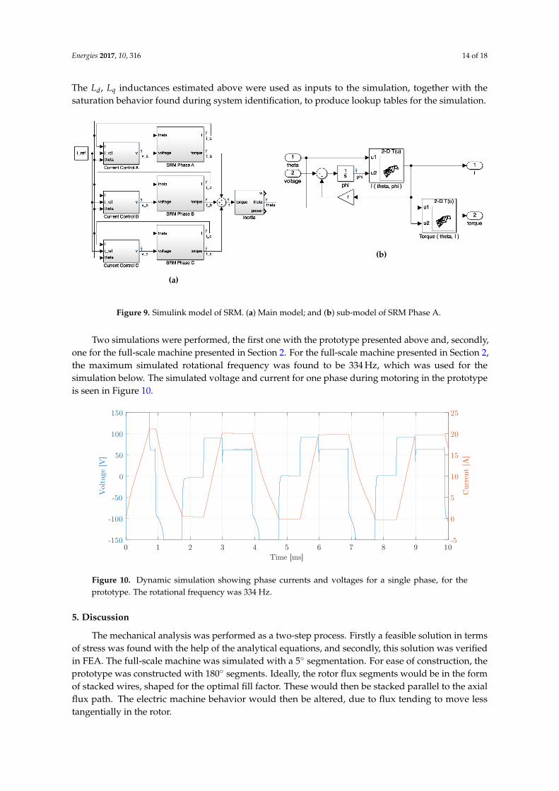
For each point in Figure 8b, 2000 switching periods were recorded per angle and current.The prototype rotor was held fixed at 12 different angles, and the current was measured in stepsof 1 A from 0 A to 20 A. The result of different inductance estimations can be seen in Figure 8a.
Ld
Lq
(a)(b)
Figure 8. In (a), the Ld, Lq as retrieved from five different methods are presented: analytical, 3DFEM with linear steel, 3D FEM with nonlinear steel, inductance meter, inductance estimation fromv and i. A relatively low magnetization was used for the nonlinear FEM computation (I = 5 A), andthe difference from the linear FEM value depends on local saturation points. In (b), a map of L(θ, I)is shown.
4. Dynamic Simulation
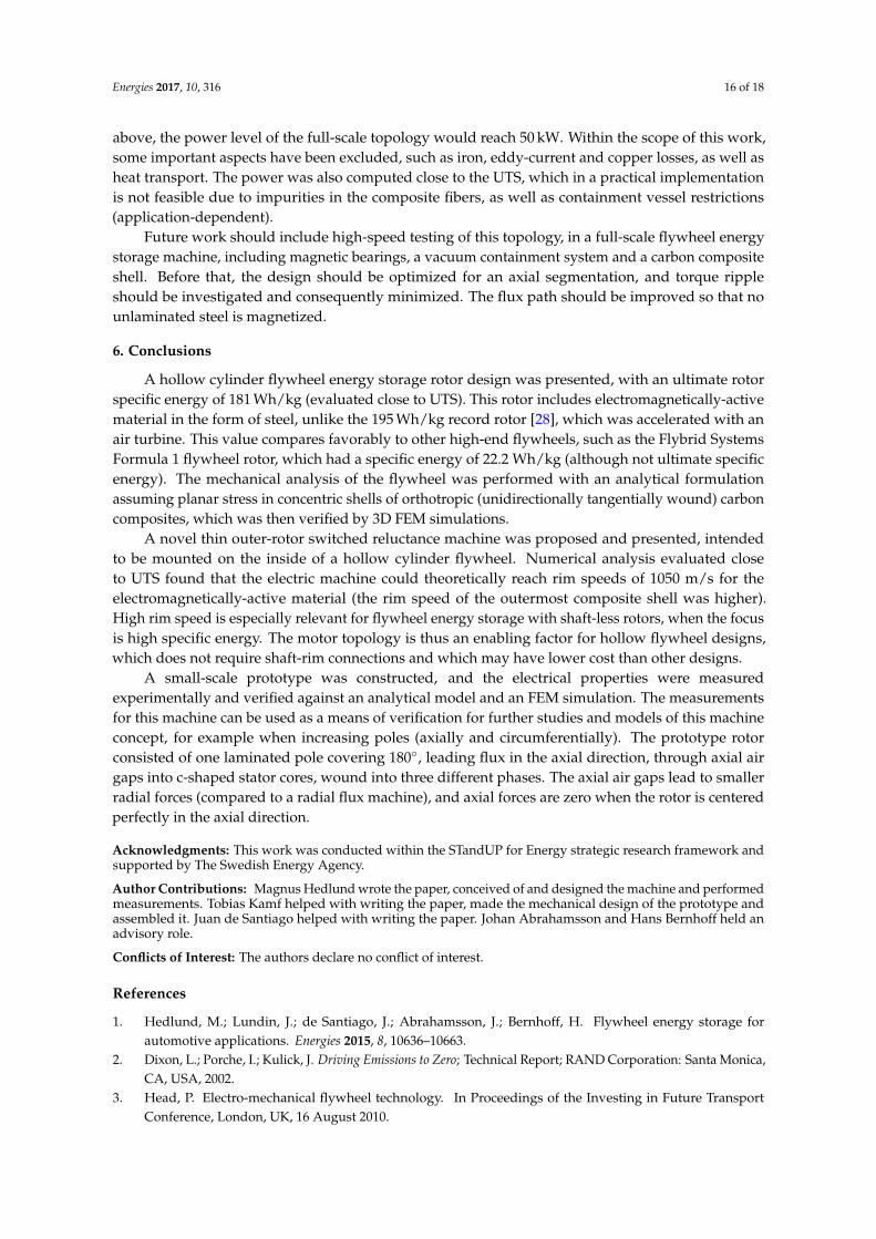
A dynamic simulation was performed in MATLAB Simulink (Mathworks, Natick, MA, USA) inorder to estimate performance during higher speeds than the small prototype presented above cansustain. A flux-based state model for each phase was used to describe the system, as seen in Figure 9.
Energies 2017, 10, 316 14 of 18
The Ld, Lq inductances estimated above were used as inputs to the simulation, together with thesaturation behavior found during system identification, to produce lookup tables for the simulation.
(a)
(b)
Figure 9. Simulink model of SRM. (a) Main model; and (b) sub-model of SRM Phase A.
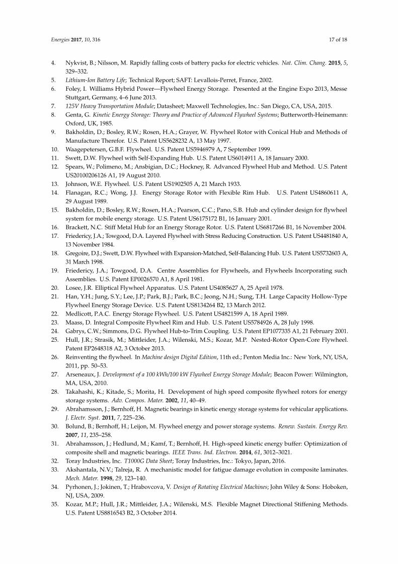
Two simulations were performed, the first one with the prototype presented above and, secondly,one for the full-scale machine presented in Section 2. For the full-scale machine presented in Section 2,the maximum simulated rotational frequency was found to be 334 Hz, which was used for thesimulation below. The simulated voltage and current for one phase during motoring in the prototypeis seen in Figure 10.
0 1 2 3 4 5 6 7 8 9 10
Time [ms]
-150
-100
-50
0
50
100
150
Vol
tage
[V
]
-5
0
5
10
15
20
25
Curr
ent
[A]
Figure 10. Dynamic simulation showing phase currents and voltages for a single phase, for theprototype. The rotational frequency was 334 Hz.
5. Discussion
The mechanical analysis was performed as a two-step process. Firstly a feasible solution in termsof stress was found with the help of the analytical equations, and secondly, this solution was verifiedin FEA. The full-scale machine was simulated with a 5◦ segmentation. For ease of construction, theprototype was constructed with 180◦ segments. Ideally, the rotor flux segments would be in the formof stacked wires, shaped for the optimal fill factor. These would then be stacked parallel to the axialflux path. The electric machine behavior would then be altered, due to flux tending to move lesstangentially in the rotor.

Energies 2017, 10, 316 15 of 18
The 3D flux path in the proposed topology implies 3D FEM solutions, which demand much interms of computing power due to the large meshes required. Saturation behavior is also very importantin SR machines, implying that a nonlinear material solver is needed, as well. In order to optimize theelectrical properties of the machine, a faster approximation would need to be developed and verified.
The analytic solution presented did provide acceptable results for the geometry chosen, althoughunderestimating leakage flux (manifested via a low Lq). It is likely that for an optimized design,in which for example, axial rotor segments are used, or a substantially shorter axial flux path in general,the analytical solutions will deviate more due to unmodeled leakage fluxes.
The practical construction of the prototype machine revealed a few important details. It wasfound to be hard to have laminated steel through all of the flux path, especially on the stator side of theair gap. A better solution than to use solid steel wedges could be to mount rings on the stator stackedin the ϕz-plane; especially since some of the flux must move tangentially there. The winding processwas found to simple and straightforward. Fixing the rotor laminations in place with wedges (as seenin Figure 3a) required special manufacturing, which should be optimized. If using axially-orientedwires as suggested above, an epoxy matrix or similar would probably be beneficial.
The measurements in Figure 8b seem to contain high saturation regions of decreasing inductancearound Ld, which would imply negative torque. However, the actual torque is not negative,so the valley-shape is attributed to some physical loss-related effect and/or errors in the estimationassumptions, whose analysis is outside the scope of this paper. Most probably though, the effect is dueto some of the smaller components in the stator not being laminated, in which eddy-currents are beinginduced. The effect can be seen in Figure 6, where the current seems to rise faster just after a switch.
The dynamical simulation showed that the machine does have inductance plateaus, in whichthere is no back-emf. These plateaus can decrease the reactive power requirements of the powerelectronics, by allowing for the current to settle. The saturation behavior was included in the model,but no torque ripple or harmonic distortion was modeled. Although the system identification wasevaluated at 240 different operating points, the angular resolution was deemed too low to model theseproperties satisfactorily.
A high peripheral velocity is not commonly optimized in electric machines. However, for anelectric machine mounted close to the periphery of a flywheel energy storage, maximal peripheralvelocity is directly related to the specific energy of the machine. The full-scale machine is seen toexhibit a large radius and high peripheral velocity when evaluated close to UTS.
The inductance map can be used to compute mean mechanical power P given speed ω using thefollowing relations:
P = τmeanω, (21)
where τmean is the mean torque developed when the rotor is passing from the d to the q position.The instantaneous torque can be found by differentiating the co-energy W ′ [50]:
τmean = mean(
∂W ′
∂θ
)I constant
=∆W ′
∆θ=
∫ i1=Ii1=0 Φd −Φqdi1
θd − θq, (22)
The flux is substituted by integration of Equation (17), which yields:
P = ω
∫ i1=Ii1=0
∫ i2=i1i2=0 L(θd, i2)− L(θq, i2)di2di1
θd − θq, (23)
For the full-scale machine, a larger radius allows for larger winding area. A basic estimate ofthe full-scale machine rating can be extrapolated assuming all factors scale linearly. For example,assume the stator and rotor poles were tripled, as well as the winding area (assuming volume andsufficient cooling was available) and that the axial length of the rotor was increased and split intoten axial segments, with a ten-fold increase of parallelly-wound windings. Under the assumptions
Energies 2017, 10, 316 16 of 18
above, the power level of the full-scale topology would reach 50 kW. Within the scope of this work,some important aspects have been excluded, such as iron, eddy-current and copper losses, as well asheat transport. The power was also computed close to the UTS, which in a practical implementationis not feasible due to impurities in the composite fibers, as well as containment vessel restrictions(application-dependent).
Future work should include high-speed testing of this topology, in a full-scale flywheel energystorage machine, including magnetic bearings, a vacuum containment system and a carbon compositeshell. Before that, the design should be optimized for an axial segmentation, and torque rippleshould be investigated and consequently minimized. The flux path should be improved so that nounlaminated steel is magnetized.
6. Conclusions
A hollow cylinder flywheel energy storage rotor design was presented, with an ultimate rotorspecific energy of 181 Wh/kg (evaluated close to UTS). This rotor includes electromagnetically-activematerial in the form of steel, unlike the 195 Wh/kg record rotor [28], which was accelerated with anair turbine. This value compares favorably to other high-end flywheels, such as the Flybrid SystemsFormula 1 flywheel rotor, which had a specific energy of 22.2 Wh/kg (although not ultimate specificenergy). The mechanical analysis of the flywheel was performed with an analytical formulationassuming planar stress in concentric shells of orthotropic (unidirectionally tangentially wound) carboncomposites, which was then verified by 3D FEM simulations.
A novel thin outer-rotor switched reluctance machine was proposed and presented, intendedto be mounted on the inside of a hollow cylinder flywheel. Numerical analysis evaluated closeto UTS found that the electric machine could theoretically reach rim speeds of 1050 m/s for theelectromagnetically-active material (the rim speed of the outermost composite shell was higher).High rim speed is especially relevant for flywheel energy storage with shaft-less rotors, when the focusis high specific energy. The motor topology is thus an enabling factor for hollow flywheel designs,which does not require shaft-rim connections and which may have lower cost than other designs.
A small-scale prototype was constructed, and the electrical properties were measuredexperimentally and verified against an analytical model and an FEM simulation. The measurementsfor this machine can be used as a means of verification for further studies and models of this machineconcept, for example when increasing poles (axially and circumferentially). The prototype rotorconsisted of one laminated pole covering 180◦, leading flux in the axial direction, through axial airgaps into c-shaped stator cores, wound into three different phases. The axial air gaps lead to smallerradial forces (compared to a radial flux machine), and axial forces are zero when the rotor is centeredperfectly in the axial direction.
Acknowledgments: This work was conducted within the STandUP for Energy strategic research framework andsupported by The Swedish Energy Agency.
Author Contributions: Magnus Hedlund wrote the paper, conceived of and designed the machine and performedmeasurements. Tobias Kamf helped with writing the paper, made the mechanical design of the prototype andassembled it. Juan de Santiago helped with writing the paper. Johan Abrahamsson and Hans Bernhoff held anadvisory role.
Conflicts of Interest: The authors declare no conflict of interest.
References
1. Hedlund, M.; Lundin, J.; de Santiago, J.; Abrahamsson, J.; Bernhoff, H. Flywheel energy storage forautomotive applications. Energies 2015, 8, 10636–10663.
2. Dixon, L.; Porche, I.; Kulick, J. Driving Emissions to Zero; Technical Report; RAND Corporation: Santa Monica,CA, USA, 2002.
3. Head, P. Electro-mechanical flywheel technology. In Proceedings of the Investing in Future TransportConference, London, UK, 16 August 2010.
Energies 2017, 10, 316 17 of 18
4. Nykvist, B.; Nilsson, M. Rapidly falling costs of battery packs for electric vehicles. Nat. Clim. Chang. 2015, 5,329–332.
5. Lithium-Ion Battery Life; Technical Report; SAFT: Levallois-Perret, France, 2002.6. Foley, I. Williams Hybrid Power—Flywheel Energy Storage. Presented at the Engine Expo 2013, Messe
Stuttgart, Germany, 4–6 June 2013.7. 125V Heavy Transportation Module; Datasheet; Maxwell Technologies, Inc.: San Diego, CA, USA, 2015.8. Genta, G. Kinetic Energy Storage: Theory and Practice of Advanced Flywheel Systems; Butterworth-Heinemann:
Oxford, UK, 1985.9. Bakholdin, D.; Bosley, R.W.; Rosen, H.A.; Grayer, W. Flywheel Rotor with Conical Hub and Methods of
Manufacture Therefor. U.S. Patent US5628232 A, 13 May 1997.10. Waagepetersen, G.B.F. Flywheel. U.S. Patent US5946979 A, 7 September 1999.11. Swett, D.W. Flywheel with Self-Expanding Hub. U.S. Patent US6014911 A, 18 January 2000.12. Spears, W.; Polimeno, M.; Ansbigian, D.C.; Hockney, R. Advanced Flywheel Hub and Method. U.S. Patent
US20100206126 A1, 19 August 2010.13. Johnson, W.E. Flywheel. U.S. Patent US1902505 A, 21 March 1933.14. Flanagan, R.C.; Wong, J.J. Energy Storage Rotor with Flexible Rim Hub. U.S. Patent US4860611 A,
29 August 1989.15. Bakholdin, D.; Bosley, R.W.; Rosen, H.A.; Pearson, C.C.; Pano, S.B. Hub and cylinder design for flywheel
system for mobile energy storage. U.S. Patent US6175172 B1, 16 January 2001.16. Brackett, N.C. Stiff Metal Hub for an Energy Storage Rotor. U.S. Patent US6817266 B1, 16 November 2004.17. Friedericy, J.A.; Towgood, D.A. Layered Flywheel with Stress Reducing Construction. U.S. Patent US4481840 A,
13 November 1984.18. Gregoire, D.J.; Swett, D.W. Flywheel with Expansion-Matched, Self-Balancing Hub. U.S. Patent US5732603 A,
31 March 1998.19. Friedericy, J.A.; Towgood, D.A. Centre Assemblies for Flywheels, and Flywheels Incorporating such
Assemblies. U.S. Patent EP0026570 A1, 8 April 1981.20. Losee, J.R. Elliptical Flywheel Apparatus. U.S. Patent US4085627 A, 25 April 1978.21. Han, Y.H.; Jung, S.Y.; Lee, J.P.; Park, B.J.; Park, B.C.; Jeong, N.H.; Sung, T.H. Large Capacity Hollow-Type
Flywheel Energy Storage Device. U.S. Patent US8134264 B2, 13 March 2012.22. Medlicott, P.A.C. Energy Storage Flywheel. U.S. Patent US4821599 A, 18 April 1989.23. Maass, D. Integral Composite Flywheel Rim and Hub. U.S. Patent US5784926 A, 28 July 1998.24. Gabrys, C.W.; Simmons, D.G. Flywheel Hub-to-Trim Coupling. U.S. Patent EP1077335 A1, 21 February 2001.25. Hull, J.R.; Strasik, M.; Mittleider, J.A.; Wilenski, M.S.; Kozar, M.P. Nested-Rotor Open-Core Flywheel.
Patent EP2648318 A2, 3 October 2013.26. Reinventing the flywheel. In Machine design Digital Edition, 11th ed.; Penton Media Inc.: New York, NY, USA,
2011, pp. 50–53.27. Arseneaux, J. Development of a 100 kWh/100 kW Flywheel Energy Storage Module; Beacon Power: Wilmington,
MA, USA, 2010.28. Takahashi, K.; Kitade, S.; Morita, H. Development of high speed composite flywheel rotors for energy
storage systems. Adv. Compos. Mater. 2002, 11, 40–49.29. Abrahamsson, J.; Bernhoff, H. Magnetic bearings in kinetic energy storage systems for vehicular applications.
J. Electr. Syst. 2011, 7, 225–236.30. Bolund, B.; Bernhoff, H.; Leijon, M. Flywheel energy and power storage systems. Renew. Sustain. Energy Rev.
2007, 11, 235–258.31. Abrahamsson, J.; Hedlund, M.; Kamf, T.; Bernhoff, H. High-speed kinetic energy buffer: Optimization of
composite shell and magnetic bearings. IEEE Trans. Ind. Electron. 2014, 61, 3012–3021.32. Toray Industries, Inc. T1000G Data Sheet; Toray Industries, Inc.: Tokyo, Japan, 2016.33. Akshantala, N.V.; Talreja, R. A mechanistic model for fatigue damage evolution in composite laminates.
Mech. Mater. 1998, 29, 123–140.34. Pyrhonen, J.; Jokinen, T.; Hrabovcova, V. Design of Rotating Electrical Machines; John Wiley & Sons: Hoboken,
NJ, USA, 2009.35. Kozar, M.P.; Hull, J.R.; Mittleider, J.A.; Wilenski, M.S. Flexible Magnet Directional Stiffening Methods.
U.S. Patent US8816543 B2, 3 October 2014.
Energies 2017, 10, 316 18 of 18
36. Tanujaya, M.; Lee, D.H.; Ahn, J.W. Design a novel switched reluctance motor for neighborhoods electricvehicle. In Proceedings of the 2011 IEEE 8th International Conference on Power Electronics and ECCE Asia(ICPE ECCE), Seogwipo, Korea, 30 May–3 June 2011; pp. 1674–1681.
37. Andrade, R.D.; Ferreira, A.C.; Sotelo, G.G.; Neto, J.L.S.; Rolim, L.G.B.; Suemitsu, W.I.; Bessa, M.F.;Stephan, R.M.; Nicolsky, R. Voltage sags compensation using a superconducting flywheel energy storagesystem. IEEE Trans. Appl. Supercond. 2005, 15, 2265–2268.
38. Rolim, L.G.B.; Ferreira, A.C.; Sotelo, G.G.; de Andrade, R. Flywheel generator with switched reluctancemachine. In Proceedings of the International Conference on Electrical Machines (ICEM), Bruges, Belgium,26–28 August 2002.
39. Iglesias, I.J.; Garcia-Tabares, L.; Agudo, A.; Cruz, I.; Arribas, L. Design and simulation of a stand-alonewind-diesel generator with a flywheel energy storage system to supply the required active and reactivepower. In Proceedings of the 2000 IEEE 31st Annual Power Electronics Specialists Conference, Galway,Ireland, 23 June 2000; Volume 3, pp. 1381–1386.
40. Cardenas, R.; Pena, R.; Perez, M.; Clare, J.; Asher, G.; Wheeler, P. Power smoothing using a flywheel drivenby a switched reluctance machine. IEEE Trans. Ind. Electron. 2006, 53, 1086–1093.
41. Kiyota, K.; Chiba, A. Design of switched reluctance motor competitive to 60-kW IPMSM in third-generationhybrid electric vehicle. IEEE Trans. Ind. Electron. 2012, 48, 2303–2309.
42. Chen, H.; Gu, J.J. Switched reluctance motor drive with external rotor for fan in air conditioner. IEEE/ASMETrans. Mechatron. 2013, 18, 1448–1458.
43. Mao, S.H.; Tsai, M.C. A novel switched reluctance motor with C-core stators. IEEE Trans. Magnet. 2005, 41,4413–4420.
44. Madhavan, R.; Fernandes, B.G. Performance improvement in the axial flux-segmented rotor-switchedreluctance motor. IEEE Trans. Energy Convers. 2014, 29, 641–651.
45. Shibamoto, T.; Nakamura, K.; Goto, H.; Ichinokura, O. A design of axial-gap switched reluctance motor forin-wheel direct-drive EV. In Proceedings of the 2012 XXth International Conference on Electrical Machines(ICEM), Marseille, France, 2–5 September 2012; pp. 1160–1165.
46. Madhavan, R.; Fernandes, B.G. Comparative analysis of axial flux SRM topologies for electric vehicleapplication. In Proceedings of the 2012 IEEE International Conference on Power Electronics, Drives andEnergy Systems (PEDES), Bengaluru, India, 16–19 December 2012; pp. 1–6.
47. Labak, A.; Kar, N.C. Designing and prototyping a novel five-phase pancake-shaped axial-flux SRM forelectric vehicle application through dynamic FEA incorporating flux-tube modeling. IEEE Trans. Ind. Appl.2013, 49, 1276–1288.
48. Abrahamsson, J.; de Oliveira, J.G.; de Santiago, J.; Lundin, J.; Bernhoff, H. On the efficiency of atwo-power-level flywheel-based all-electric driveline. Energies 2012, 5, 2794–2817.
49. Liu, X.; Zhu, Z.Q.; Hasegawa, M.; Pride, A.; Deohar, R.; Maruyama, T.; Chen, Z. Performance comparisonbetween unipolar and bipolar excitations in switched reluctance machine with sinusoidal and rectangularwaveforms. In Proceedings of the 2011 IEEE Energy Conversion Congress and Exposition (ECCE), Phoenix,AZ, USA, 17–22 September 2011; pp. 1590–1595.
50. Miller, T.J.E. Switched Reluctance Motors and Their Control; Magna Physics, Oxford University Press: Oxford,UK, 1993.
51. Cogent. Electrical Steel Non Oriented Fully Processed; Datasheet; Cogent Power Ltd.: London, UK, 2002.52. Deutsche Edelstahlwerke Gmbh. Chromium-Nickel Austenitic Stainless Steel; Datasheet; Deutsche
Edelstahlwerke Gmbh: Witten, Germany, 2014.53. Wahl, A.; Beeuwkes, R. Stress concentration produced by holes and notches. Am. Soc. Mech. Eng. Trans.
1934, 56, 617–636.54. Wangsness, R.K. Electromagnetic Fields; Wiley: Hoboken, NJ, USA, 1986.55. LEM. Current Transducer LA 55-P; Datasheet; LEM: Zürich, Switzerland, 2015.56. LEM. Voltage Transducer LV 25-P; Datasheet; LEM: Zürich, Switzerland, 2014.57. National Instruments. NI 9205 Data Sheet; National Instruments: Austin, TX, USA, 2015.
c© 2017 by the authors. Licensee MDPI, Basel, Switzerland. This article is an open accessarticle distributed under the terms and conditions of the Creative Commons Attribution(CC BY) license (http://creativecommons.org/licenses/by/4.0/).