magnetothermal repair of a pmma/iron oxide magnetic nanocomposite
TRANSCRIPT
ORIGINAL CONTRIBUTION
Magnetothermal repair of a PMMA/iron oxidemagnetic nanocomposite
John A. Medford & Jeremiah W. Hubbard &
François Orange & Maxime J.-F. Guinel &Barbara O. Calcagno & Carlos Rinaldi
Received: 7 January 2014 /Revised: 4 March 2014 /Accepted: 5 March 2014 /Published online: 1 April 2014# Springer-Verlag Berlin Heidelberg 2014
Abstract We report on the magnetothermal repair of a ther-moplastic magnetic nanocomposite consisting of iron oxidenanoparticles embedded in poly(methyl methacrylate)(PMMA). The nanoparticles responded to an applied alternat-ing magnetic field by dissipating heat, raising the nanocom-posite temperature to above the glass transition temperatureand resulting in the repair of the nanocomposite. This wasdemonstrated by cutting the nanocomposite and subsequentlyjoining two pieces together under the action of an alternatingmagnetic field. Examination by optical and transmission elec-tron microscopy of the region where the two pieces werejoined demonstrated the healing and disappearance of theinterface between both pieces down to the nanoscale.
Keywords Magnetic nanoparticle . Thermoplastic . Repair .
Nanocomposite . Alternatingmagnetic field
Introduction
Repairing damaged structural materials such as nanocompos-ites in situ can be economically advantageous over replace-ment and may be the only option should a replacement part beunavailable. Repair becomes particularly valuable in isolatedlocations (e.g., remote posts or in space exploration), wheredelivery of replacement parts is challenging or impossible.While a variety of repair methods for thermoplastic polymershas been reported [1], the most common, practical, and ver-satile method is thermal annealing [2]. By increasing thetemperature of a thermoplastic above the glass transitiontemperature (Tg), polymer molecules gain enough mobilityto reptate, reorder, and diffuse [3]. Internal stresses may there-fore be relieved, and mechanical damage such as small cracksmay be conveniently repaired in relatively short times [4].With proper application of pressure, separate pieces may evenbe “welded” together along a compatible interface using avariety of annealing methods [5]. Unlike many repair methodsavailable for thermosets [6], the annealing of a thermoplasticreturns the material to its original mechanical capabilities, andsubsequent damage in the same location may be repairedrepetitively in the same fashion [7]. The most notable draw-back of the thermal repair method is the way heat is applied;the damaged material must be placed in an oven or heatingapparatus, or directly exposed to a heat source. Annealing inan oven or heating apparatus requires removal of the part to berepaired, which in some cases may not be possible or desir-able. Direct application of heat requires immediate access tothe part to be repaired and may result in unacceptableheating of nearby components. It is therefore highly desir-able to develop methods by which engineered plastics may
J. A. Medford : J. W. Hubbard :C. RinaldiDepartment of Chemical Engineering, University of Puerto Rico,Mayagüez Campus, Call Box 9000, Mayagüez,Puerto Rico 00681-9000, USA
F. Orange :M. J.<F. GuinelNanoscopy Facility, Department of Physics, College of NaturalSciences, University of Puerto Rico, PO Box 70377, San Juan,Puerto Rico 00936-8377, USA
M. J.<F. GuinelDepartment of Chemistry, College of Natural Sciences,University of Puerto Rico, PO Box 70377, San Juan,Puerto Rico 00936-8377, USA
B. O. CalcagnoDepartment of General Engineering, University of Puerto Rico,Mayagüez Campus, Call Box 9000, Mayagüez,Puerto Rico 00681-9000, USA
C. Rinaldi (*)J. Crayton Pruitt Family Department of Biomedical Engineering andDepartment of Chemical Engineering, University of Florida,PO Box 116131, Gainesville, FL 32611-6131, USAe-mail: [email protected]
Colloid Polym Sci (2014) 292:1429–1437DOI 10.1007/s00396-014-3194-z
be repaired in situ by thermal annealing without the needto remove the part and without exposing neighboring partsto heat.
An alternative to thermal annealing of thermoplasticswhich addresses the issues of accessibility and controlled heatapplication is to apply heat from within the polymer byembedding magnetic nanoparticles (MNPs) capable of dissi-pating heat through relaxation losses in an alternating mag-netic field (AMF). Such MNPs have been investigated thor-oughly for medical applications such as selective destructionof tumor cells by hyperthermia and for local drug release byremote thermal activation [8–11]. In the context of polymernanocomposites, MNPs have already been incorporated intothermoplastics, and their remote heat dissipation ability in thepresence of an AMF has led to applications such as remoteactuation of shape memory polymers [12–14]. The concept ofthermally repairing a damaged polymer using the heat dissi-pated byMNPs in an AMF is illustrated in Fig. 1 and was firstreported by Corten and Urban [15], who demonstrated therepair of a thermoplastic copolymer of poly(methyl methac-rylate)/n-butylacrylate/heptadecafluorodecyl methacrylate(PMMA/nBA/HDFMA) with embedded oleate-coated ironoxide MNPs in an AMF for a period of 2 h. Films wereprepared by coalescing iron oxide particles coated with thepolymer. Although repair of cut films was demonstrated overmultiple cycles, the surface temperatures achieved were onlyon the order of 25 to 43 °C, even at an iron oxide particleloading of 14 wt%. Higher temperatures are needed to repairmost thermoplastics of practical concern. Corten and Urban[15] claimed that due to the low thermal conductivity of thepolymer, the temperature was likely to be higher; however, acalculation of the Biot number characterizing heat conductionin the polymer relative to heat transfer in the surrounding airindicates that the temperature within the relatively smallpieces used in their experiments should have been relativelyuniform. Finally, Corten and Urban [15] did not report the
temperature of the coil used to generate the alternating mag-netic field. Although they reported the coil was cooled usingwater, it is very common for these coils to reach high temper-atures; hence, it is not clear if the temperatures achieved in thenanocomposite were due to heating by the nanoparticles ordue to heat transfer from the coil. In a subsequent study,Adzima et al. [16] reported thermal reshaping of a reversiblechemical gel consisting of a Diels-Alder cross-linked networkusing embedded chromium (IV) oxide particles (Magtrieve®).In their system, heating by the chromium (IV) oxide particleswas only significant above a threshold magnetic field, whichdepended on the concentration of the particles in the compos-ite. Thus, the steady-state temperature reached after 300 s wasa weak function of the field conditions or concentration ofparticles above this threshold field. Furthermore, reversiblechemical gels such as the one used byAdzima et al. [16] sufferfrom poor thermal stability, limiting their practical applica-tions. These previous studies motivated us to explore themagnetothermal repair of a practical and common thermo-plastic. We selected PMMA because of its higher Tg andbecause it has been the subject of numerous studies on nano-composites [17–20]. This paper demonstrates the in situmagnetothermal repair of a damaged PMMA nanocompositeby application of an AMF.
Materials and methods
Magnetic iron oxide nanoparticle preparation
Iron oxide nanoparticles were prepared by a co-precipitationsyn t h e s i s [ 25 ] , p ep t i z ed , and coa t ed w i t h 3 -methacryloxypropyltrimethoxysilane (MPS) ligands.Solutions of 11.75 g (43.5 mmol) iron (III) chloride hexahy-drate (Sigma-Aldrich, 97 %) in 100 mL degassed deionizedwater and 4.30 g (21.6 mmol) iron (II) chloride tetrahydrate
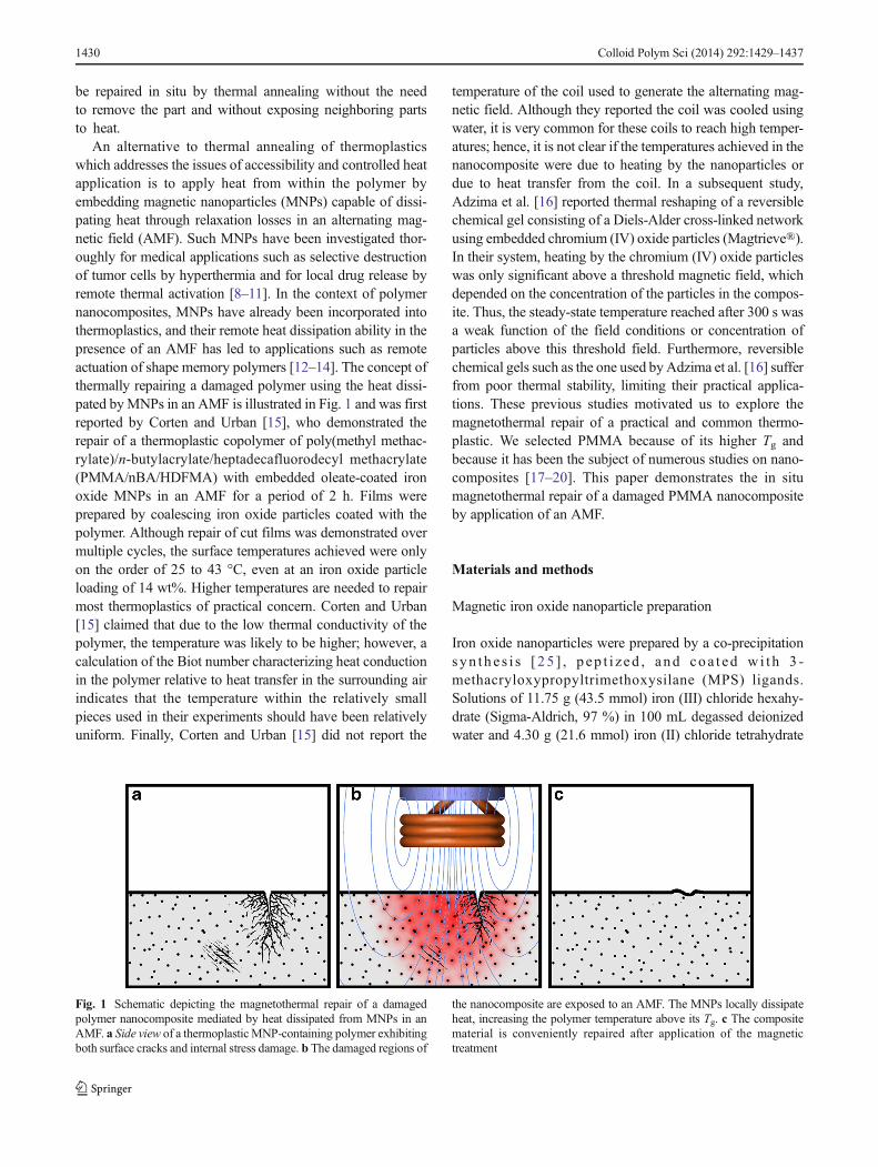
Fig. 1 Schematic depicting the magnetothermal repair of a damagedpolymer nanocomposite mediated by heat dissipated from MNPs in anAMF. a Side view of a thermoplasticMNP-containing polymer exhibitingboth surface cracks and internal stress damage. b The damaged regions of
the nanocomposite are exposed to an AMF. The MNPs locally dissipateheat, increasing the polymer temperature above its Tg. c The compositematerial is conveniently repaired after application of the magnetictreatment
1430 Colloid Polym Sci (2014) 292:1429–1437
(Sigma-Aldrich, 99 %) in 100 mL degassed deionized waterwere sonicated separately, mixed, degassed, and heated to70 °C while stirring at 100 rpm. At 70 °C, 30 mL of ammo-nium hydroxide (Fisher Chemicals, 29 %) was added. Thetemperature was quickly increased to 80 °C and the reactionproceeded for 1 h. The pH was maintained at 8 and deionizedwater was added to compensate for evaporation. After 1 h, thesolution was cooled to room temperature and centrifuged at1,500 rpm for 10 min, and the particles were magneticallydecanted, discarding the supernatant. Particles were peptizedby mixing with tetramethylammonium hydroxide (Sigma-Aldrich, 25 %) in a ~3:1 ratio, centrifuging at 1,500 rpm for10 min, and magnetically decanting. The peptization proce-dure was performed twice, and the particles were dried to athick paste for 2 days in an oven at 60 °C. MPS ligands wereattached to the particles by mixing the particle paste in 40 mLdeionized water, 144 mL anhydrous ethanol (FisherScientific), 5.5 mL ammonium hydroxide 29 %, and 30 mL(126 mmol) MPS (TCI America, >90.0 %). The solution wasmixed on a shaker table at 150 rpm for 24 h. Particles werewashed of excessMPS by mixing the particle solution in a 1:3ratio with anhydrous ethanol, centrifuging at 8,000 rpm for30 min, and magnetically decanting. This cleaning procedurewas repeated twice more, for a total of three washes. Purifiedparticles were stored in acetone at 200 mg/mL.
Magnetic iron oxide nanoparticle characterization
The hydrodynamic diameter of prepared and functionalizedmagnetic iron oxide nanoparticles was determined by dynam-ic light scattering (DLS) by diluting particle-acetone solutionswith acetone in a 1-cm glass cuvette until light transmissionwas observed. The cuvette was run in a BrookhavenInstruments BI-90 Plus DLS particle size analyzer. Particleswere characterized by thermogravimetric analysis (TGA) byadding ~50 μL particle-acetone solution to a 70-μL aluminaTGA pan, drying in an oven for 1 h at 120 °C, and running in aTA Instruments TA-2950 STARe TGA. The temperature wasramped at 10 °C/min to 120 °C and held for 20 min toeliminate moisture and solvent content and then ramped at10 °C/min to 700 °C and held for 40 min to ensure massequilibrium was reached. Specific absorption rate (SAR) mea-surements were performed by dispersing 100 mg MNPs in2 mL acetone and monitoring the temperature with a fiberoptic temperature probe (Luxtron Technologies) while anAMF was applied. Particles were characterized by Fouriertransform infrared spectroscopy (FTIR), using dried nanopar-ticle powder, and in a Varian Scimitar 800 FTIR spectrometerequipped with a Pike Technologies attenuated total reflectance(ATR) plate. Particles were characterized by superconductingquantum interference device (SQUID) magnetometry using4.2 mg dried particle powder in a Quantum Design MPMSXL-7 SQUID magnetometer. The size distribution of the
MNPs was determined by transmission electron microscopy(TEM) imaging using a Carl Zeiss LEO 922 TEM, operated at200 kV. To obtain a size distribution from TEM measure-ments, we counted 542 particles.
PMMA/iron oxide nanocomposite preparationand characterization
The PMMA/iron oxide nanocomposite sample was preparedby mixing 84.9 mg dried MPS-coated iron oxide nanoparti-cles, 50 μL acetone, 2.0 mL methyl methacrylate (MMA,18.8 mmol), and 1.9 mg azobisisobutyronitrile (AIBN,11.6 μmol) init iator in a 2.0-mL polypropylenemicrocentrifuge tube with locking lid (Fisherbrand). The tubewas sealed, agitated vigorously, and sonicated for 1 h. Thetube was then submerged upright in an 80 °C water bath for16 h to allow for complete polymerization. The sample andtube were then cut five times perpendicular to the length of thetube using a Buehler Isomet low speed saw equipped with aPro-Slicer 4×0.004×½ blade to produce two sample discs8.5 mm in diameter and 3.5 mm thick for the welding exper-iment and two characterization discs 8.5 mm in diameter and1 mm thick from the material immediately above and belowthe sample discs. A conical tip from the bottom of the reactiontube, as well as a cylindrical top, also remained. One face ofeach sample disc was polished on a Polimet Standard Polisherusing 400 grit SiC polishing paper (Allied) followed by 1,200grit SiC polishing paper (LECO). The procedure for compos-ite synthesis and preparation was repeated with the exclusionof nanoparticles to produce PMMA control samples.
Differential scanning calorimetry (DSC) and TGA wereboth performed on the characterization discs cut from thecomposite sample immediately surrounding the sample discs.A smaller disc of ~20 mg was trimmed from the center of eachtop and bottom characterization disc and ran separately in aTA Instruments model Q2000 differential scanning calorime-ter using aluminum Tzero lids and Tzero pans. The Tg wascalculated from the heat flow vs. temperature curves using TAUniversal Analysis software. The remaining trimmed materialfrom each characterization disc was run in the TGA analyzerusing 150 μL pans at 10 °C/min to 800 °C. The thermaldecomposition temperatures (Td) were taken to be the onsetpoint of each decomposition curve and determined using theintercept of lines that are parallel to the TGA curve in thepredecomposition region and in the decomposition region[26]. The PMMA control sample was characterized by DSCand TGA using the same methods described above.
The composite sample was characterized by SQUID mag-netometry to measure the equilibrium magnetization (M vs.H) curves. Magnetic measurements were normalized to themass of inorganic nanoparticle present in the sample, deter-mined from the remnant mass at the end of a TGA scan ofthe sample.
Colloid Polym Sci (2014) 292:1429–1437 1431
SAR measurements and magnetothermal repairof PMMA/iron oxide composites
The two sample discs were placed together in a plugged15-mL centrifuge tube with polished faces held in contact bythe force of the tightened lid. The sample and holder wereplaced in the middle of the coil (four turns, 3.16 cm ID,2.97 cm height) of a RDO Induction Heating SolutionsModel HFI 3-135/400 induction heater. Temperature wasmonitored using a FLIR Thermacam A20 Researcher infraredcamera, which viewed the sample through a small hole in thesample holder lid. Sample temperature was monitored bymeasuring the surface temperature of the top of the samplethrough this hole.
SAR measurements were made by first allowing the sam-ple to reach thermal equilibrium, followed by turning on theAMF at a selected field amplitude between 10 and 50 kA/m.The SAR value was determined from the initial rate of tem-perature rise dT/dt|t=0
SAR ¼ msbCp
mIO
dT
dt
�
�
�
�
t¼0
where ms is the mass of the sample, bCp is the specific heatcapacity of the sample, andmIO is the mass of iron oxide in thesample. Here we approximated the heat capacity of the sampleto be that of the matrix in which the particles are dispersed:acetone (bCp ¼ 2; 150 J kg−1 K−1 ) in the case of measurementsof free particles and PMMA (bCp ¼ 1; 466 J kg−1 K−1 ) in thecase of the nanocomposite samples. For SARmeasurements ofthe nanoparticles dispersed in acetone, care was taken not toreach the boiling point (56 °C) of the solvent.
In a representative magnetothermal repair experiment, theinduction heater was set to ~50 kA/m at 233±5 kHz for 5 minto ramp the temperature of the sample to 130 °C. The AMFwas then lowered to ~25 kA/m and 233±5 kHz to hold thetemperature at 130 °C for 60 min. After 60 min, the inductionheater was powered off and the sample was allowed to natu-rally cool to room temperature. This procedure was repeatedfor the PMMA control sample.
Characterization of samples from magnetothermal repairexperiment
The repaired cylinder was cut perpendicular to the interfacebetween the two former pieces using the previously men-tioned low speed saw. One half was polished (using thepreviously mentioned procedure) to reveal the interface ofthe weld seam, while the other half was left unpolished.Optical microscopy was performed on both halves using aNikon SMZ 1500 optical microscope. Approximately 100 nmthick lamellas from the interfacial region between the twopieces joined during the magnetothermal repair experiment
were cut using a Leica EM UC6 ultramicrotome and a dia-mond knife. The lamellas were placed on 300 mesh copperTEM support grids. The lamellas were examined using aJEOL JSM-7500F scanning electron microscope (SEM)equipped with a transmission electron detector (TED).Images were recorded at an accelerating voltage of 15 kV.To test the quality of the junction and its possible influence onthe nanoparticle aggregates, the spatial distribution of theaggregates was measured using the Geological ImageAnalysis Software [27], which uses nearest neighbor statistics.
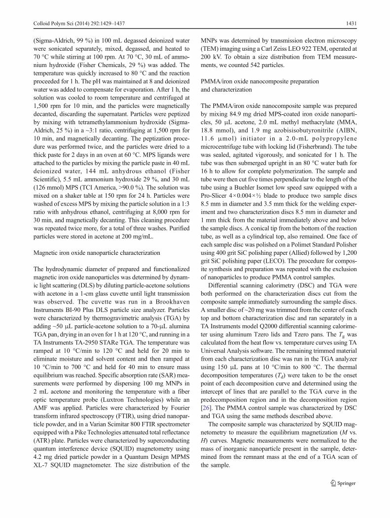
Fig. 2 a Typical TEMmicrograph recorded fromMPS-coated iron oxidenanoparticles. b Size distribution histograms of the diameter of theinorganic cores measured from TEM images (number weighted) and ofthe hydrodynamic diameter obtained by DLS (volume weighted)
1432 Colloid Polym Sci (2014) 292:1429–1437
Measurements were made from TEM micrographs of thelamellas, which included the interface. Analyses were carriedon the entire image, and on three equal parts of the image,which included both sides of the interface and the interfaceitself.
Results and discussion
Characterization of magnetic nanoparticles
TEM observations of the MPS-coated MNPs (Fig. 2) showedan average primary particle diameter of 13 nm, with standarddeviation of 3 nm, and significant aggregation into clustersthat were 100–200 nm in characteristic length. According to
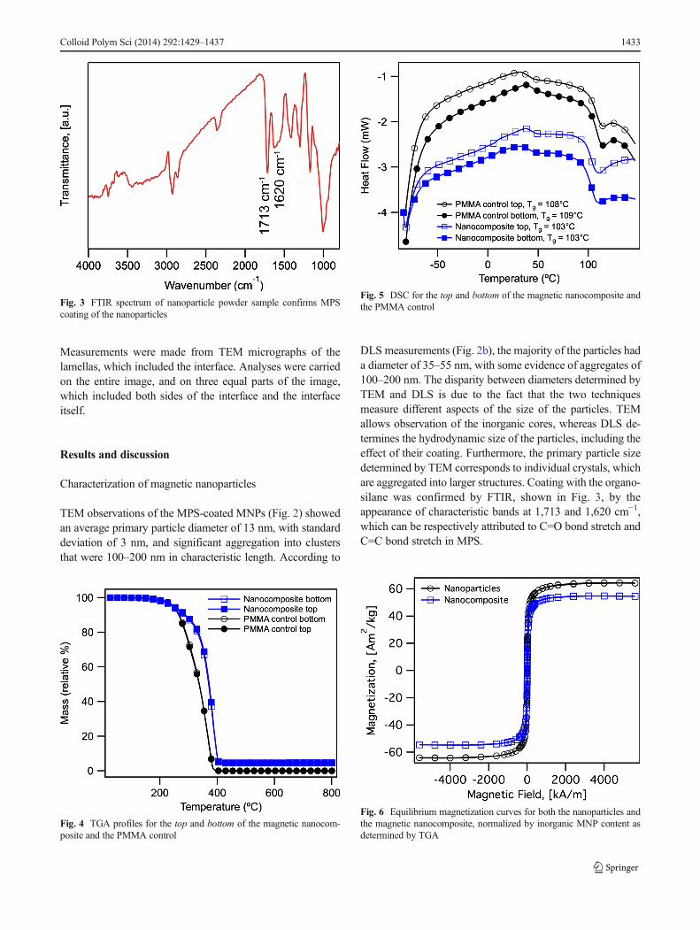
DLS measurements (Fig. 2b), the majority of the particles hada diameter of 35–55 nm, with some evidence of aggregates of100–200 nm. The disparity between diameters determined byTEM and DLS is due to the fact that the two techniquesmeasure different aspects of the size of the particles. TEMallows observation of the inorganic cores, whereas DLS de-termines the hydrodynamic size of the particles, including theeffect of their coating. Furthermore, the primary particle sizedetermined by TEM corresponds to individual crystals, whichare aggregated into larger structures. Coating with the organo-silane was confirmed by FTIR, shown in Fig. 3, by theappearance of characteristic bands at 1,713 and 1,620 cm−1,which can be respectively attributed to C=O bond stretch andC=C bond stretch in MPS.
Fig. 5 DSC for the top and bottom of the magnetic nanocomposite andthe PMMA control
Fig. 6 Equilibrium magnetization curves for both the nanoparticles andthe magnetic nanocomposite, normalized by inorganic MNP content asdetermined by TGA
Fig. 4 TGA profiles for the top and bottom of the magnetic nanocom-posite and the PMMA control
Fig. 3 FTIR spectrum of nanoparticle powder sample confirms MPScoating of the nanoparticles
Colloid Polym Sci (2014) 292:1429–1437 1433
Characterization of magnetic nanocomposites
TEM showed the particles to be dispersed as aggregatesthroughout the polymer nanocomposite (Fig. 9). The overallsize of the aggregates did not appear to change between thefree coated nanoparticles and the particles embedded in thepolymer; hence, we concluded that this aggregation was theresult of the MPS coating and not due to the preparation of thenanocomposite itself.
Characterization by TGA and DSC of samples taken fromthe two ends of the nanocomposite demonstrates that the Td andTg were fairly uniform throughout the sample (Figs. 4 and 5).Comparison between the magnetic nanocomposite and PMMAcontrol indicated an increase in Td from 255 to 330 °C, due tothe presence of the MNPs, whereas the Tg changed onlyslightly from ~108 to ~103 °C. Similar observations of anincrease in Td with relatively little change in Tg were reportedby Kirchberg et al. [21] for PMMA/Fe3O4 nanocomposites. Innanocomposites, the change in Tg is due to a change in mobilityof the polymer chains at the polymer/filler interface [22].Reduced mobility due to a strong attraction translates to anincrease in Tg. However, this effect is proportional to the totalinterfacial area. For cases where the particles are aggregatedinto clusters and the distance between clusters is large, theeffect is much less pronounced [23]. For this material, the
particles cross-link with the polymer; hence, they would beexpected to increase the Tg. However, as shown below, theywere aggregates of 100–200 nm spaced ~300 nm apart. Thismay be responsible for the reduced effect of the nanofiller onthe Tg. Characterization of the magnetic nanocomposite byTGA indicated that there were 4.5 wt% inorganic MNPs.
Equilibrium magnetization measurements of the nanopar-ticles and magnetic nanocomposite, shown in Fig. 6, demon-strated superparamagnetism at room temperature, as no sig-nificant remanence and coercivity was observed and the datafollowed the predictions of the Langevin function. The satu-ration magnetization, obtained by normalizing the magnetiza-tion with respect to the mass of iron oxide in each sample, was
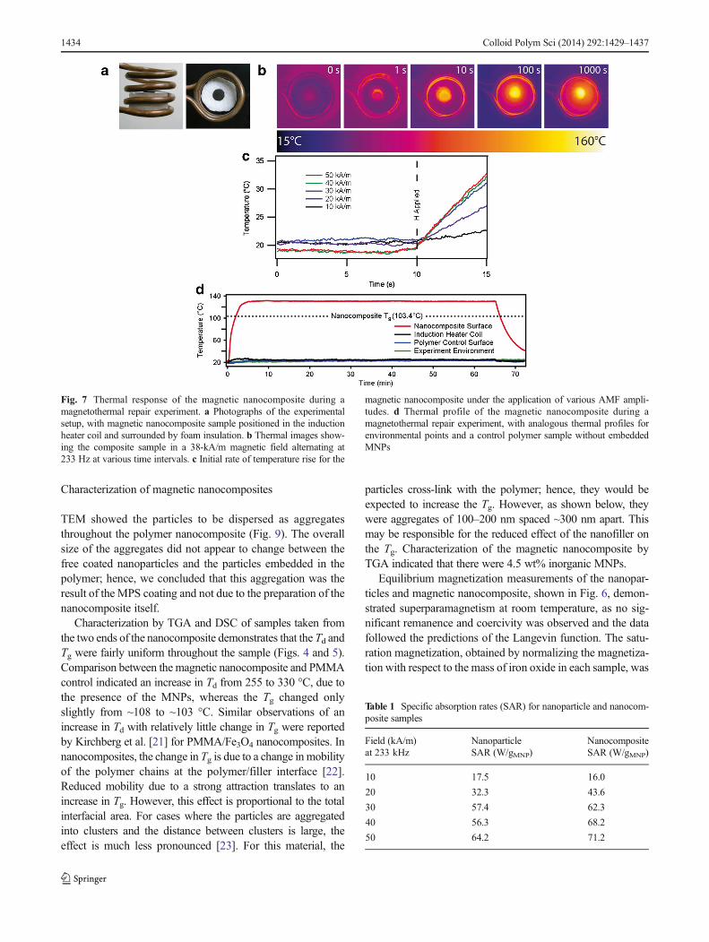
Fig. 7 Thermal response of the magnetic nanocomposite during amagnetothermal repair experiment. a Photographs of the experimentalsetup, with magnetic nanocomposite sample positioned in the inductionheater coil and surrounded by foam insulation. b Thermal images show-ing the composite sample in a 38-kA/m magnetic field alternating at233 Hz at various time intervals. c Initial rate of temperature rise for the
magnetic nanocomposite under the application of various AMF ampli-tudes. d Thermal profile of the magnetic nanocomposite during amagnetothermal repair experiment, with analogous thermal profiles forenvironmental points and a control polymer sample without embeddedMNPs
Table 1 Specific absorption rates (SAR) for nanoparticle and nanocom-posite samples
Field (kA/m)at 233 kHz
NanoparticleSAR (W/gMNP)
NanocompositeSAR (W/gMNP)
10 17.5 16.0
20 32.3 43.6
30 57.4 62.3
40 56.3 68.2
50 64.2 71.2
1434 Colloid Polym Sci (2014) 292:1429–1437
similar for the nanoparticles (64 Am2/kg) and for the nano-composite (55 Am2/kg). The values of the saturation magne-tization are in the usual range reported for iron oxide nano-particles. A fit of the equilibrium magnetization data to theLangevin function weighted by a lognormal size distribution
yielded a magnetic diameter of 9.4 nm (geometric deviation of0.4) for the free nanoparticles and 9.1 nm (geometric deviationof 0.4) for the nanoparticles embedded in the nanocomposite.Thus, embedding the nanoparticles in the nanocomposite didnot appear to change their magnetic properties.
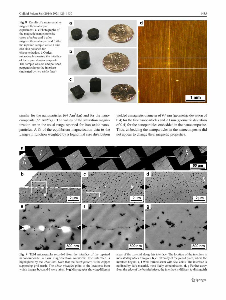
Fig. 8 Results of a representativemagnetothermal repairexperiment. a–c Photographs ofthe magnetic nanocompositetaken a before and b aftermagnetothermal repair and c afterthe repaired sample was cut andone side polished forcharacterization. d Opticalmicrograph showing the interfaceof the repaired nanocomposite.The sample was cut and polishedperpendicular to the interface(indicated by two white lines)
Fig. 9 TEM micrographs recorded from the interface of the repairednanocomposite. a Low magnification overview. The interface ishighlighted by the white line. Note that the black pattern is the coppersupporting grid mesh. The white triangles point to the locations fromwhich images b, c, and dwere taken. b–gMicrographs showing different
areas of the material along this interface. The location of the interface isindicated by black triangles. b, e Extremity of the joined piece, where theinterface begins. c, f Well-formed seam with few voids. The interface isoutlined by dark material, most likely contamination. d, g Further awayfrom the edge of the bonded piece, the interface is difficult to distinguish
Colloid Polym Sci (2014) 292:1429–1437 1435
Magnetothermal repair experiments
The two pieces held against each other and placed in the AMFof an induction heater coil are shown in the picture of Fig. 7a.During this time, the temperature of the nanocomposite waskept at Tg+27 °C (~130 °C), as determined using a FLIRThermacam A20 infrared thermal camera used to record thesurface temperature of the magnetic nanocomposite duringAMF treatment in the induction heater. Thermal images ofthe nanocomposite sample are displayed in Fig. 7b. The initialrate of temperature rise upon application of an AMF forseveral selected field strengths (Fig. 7c) illustrates the fielddependence of the energy dissipation rate of the nanoparticles.One way to characterize this energy dissipation rate is throughthe SAR [24], calculated from the initial rate of temperaturerise upon application of an AMF to a MNP sample. Weobserved similar values for the SAR of the MNPs and for
the as-prepared nanocomposites (Table 1). Although the SARincreased with the applied magnetic field amplitude, a satura-tion value was evident at the highest fields. A representativethermal profile of a magnetothermal repair experiment isshown in Fig. 7d. As is evident in Fig. 7b, d, the primarysource of heat in the experiment is from the magnetic nano-composite, which easily and quickly reaches temperaturesabove the Tg of the polymer matrix. Of note, the temperatureof the coil used to generate the AMFwas kept close to ambienttemperature and was much lower than the temperature of thenanocomposite sample, as is evident in Fig. 7b and shown inFig. 7d.
Pictures of the magnetic nanocomposite sample before andafter the magnetothermal repair experiment are displayed inFig. 8a–c. Inspection showed evidence of good bonding, witha very limited apparent interface being the only evidence thatthe two pieces were once separated. This observation was
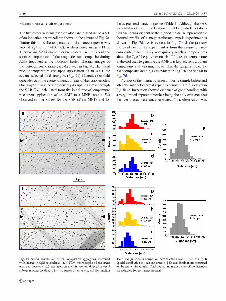
Fig. 10 Spatial distribution of the nanoparticle aggregates, measuredwith nearest neighbor statistics. a, f TEM micrographs of the areasanalyzed, located at 0.5 mm apart on the thin section, divided in equalsub-areas corresponding to the two pieces of polymers, and the junction
itself. The junction is horizontal, between the black arrows. b–d, g, hSpatial distribution in each sub-areas. e, j Spatial distributions measuredon the entire micrographs. Total counts and mean values of the distancesare indicated for each measurement
1436 Colloid Polym Sci (2014) 292:1429–1437

reinforced by optical microscopy (Fig. 8d), which shows goodbonding across most of the interface. Actually, most of theinterface cannot be distinguished from the bulk polymer piece.
TEM observations made along the interface (Fig. 9a) pro-vided further confirmation of the successful magnetothermalrepair. Some very small voids remained along the interface(Fig. 9b, e), but even at highmagnification, the interface couldhardly be distinguished (Fig. 9c, d, f, g). Throughout most ofthe piece, the only evidence of the interface was some nano-scale gaps (Fig. 9c) and a thin trail of debris which is possiblythe result of the cutting and polishing procedure used toprepare the pieces before the experiment (Fig. 9f, g).
As noted above, the nanoparticles appeared as 100–200 nmaggregates, evenly distributed throughout the polymer. Ananalysis of the average cluster-to-cluster separation for regionsclose to and away from the junction did not reveal significantdifferences in the distributions of the particles (Fig. 10), whichindicates that even though the polymer was raised to above itsTg, the nanoparticles did not migrate towards the interface.
Conclusion
The successful magnetothermal repair of a thermoplastic mag-netic nanocomposite consisting of MPS-coated iron oxidenanoparticles in a PMMA matrix was reported. Upon appli-cation of an alternating magnetic field, the magnetic nano-composite temperature was raised above its Tg due to the heatreleased by magnetic nanoparticles embedded in the polymermatrix. Heating was shown to be due to energy dissipation bythe particles, as the temperature rise was proportional to theapplied magnetic field amplitude and the temperature of thenanocomposite was significantly higher than that of the coilused to generate the alternating magnetic field. Detailed ex-aminations of the interface showed only the presence of verysmall voids as the only evidence of the fact that the two pieceswere once separated.
Acknowledgments This work was supported by the US National Sci-ence Foundation (DMR-0934115, HRD-0833112).
References
1. Wu DY, Meure S, Solomon D (2008) Self-healing polymeric mate-rials: a review of recent developments. Prog Polym Sci 33:479–522
2. Grewell D, Benatar A (2007) Welding of plastics: fundamentals andnew developments. Int Polym Process 22:43–60
3. Lamèthe J-F, Beauchêne P, Léger L (2005) Polymer dynamicsapplied to PEEK matrix composite welding. Aerosp Sci Technol9:233–240
4. Jud K, Kausch HH, Williams JG (1981) Fracture-mechanics studiesof crack healing and welding of polymers. J Mater Sci 16:204–210
5. Ageorges C, Ye L, Hou M (2001) Advances in fusion bondingtechniques for joining thermoplastic matrix composites: a review.Compos A Appl Sci Manuf 32:839–857
6. Mauldin TC, Kessler MR (2010) Self-healing polymers and compos-ites. Int Mater Rev 55:317–346
7. Plaisted TA, Nemat-Nasser S (2007) Quantitative evaluation of frac-ture, healing and re-healing of a reversibly cross-linked polymer.Acta Mater 55:5684–5696
8. Latorre M, Rinaldi C (2009) Applications of magnetic nanoparti-cles in medicine: magnetic fluid hyperthermia. P R Health Sci J 28:227–238
9. Hoare T, Timko BP, Santamaria J, Goya GF, Irusta S, Lau S,Stefanescu CF, Lin D, Langer R, Kohane DS (2011) Magneticallytriggered nanocomposite membranes: a versatile platform for trig-gered drug release. Nano Lett 11:1395–1400
10. Laurent S, Dutz S, Haefeli UO, Mahmoudi M (2011) Magnetic fluidhyperthermia: focus on superparamagnetic iron oxide nanoparticles.Adv Colloid Interf Sci 166:8–23
11. Rovers SA, Hoogenboom R, Kemmere MF, Keurentjes JTF (2012)Repetitive on-demand drug release by magnetic heating of iron oxidecontaining polymeric implants. Soft Matter 8:1623–1627
12. Leng J, Lan X, LiuY, Du S (2011) Shape-memory polymers and theircomposites: stimulus methods and applications. Prog Mater Sci 56:1077–1135
13. RazzaqMY, BehlM, Lendlein A (2012)Memory-effects of magneticnanocomposites. Nanoscale 4:6181–6195
14. Cai Y, Jiang J-S, Zheng B, Xie M-R (2013) Synthesis and propertiesof magnetic sensitive shape memory Fe3O4/poly(e-caprolactone)-polyurethane nanocomposites. J Appl Polym Sci 127:49–56
15. Corten CC, Urban MW (2009) Repairing polymers using an oscil-lating magnetic field. Adv Mater 21:5011–5015
16. Adzima BJ, Kloxin CJ, Bowman CN (2010) Externally triggeredhealing of a thermoreversible covalent network via self-limited hys-teresis heating. Adv Mater 22:2784–2787
17. Althues H, Henle J, Kaskel S (2007) Functional inorganic nanofillersfor transparent polymers. Chem Soc Rev 36:1454–1465
18. Xu C, Ohno K, Ladmiral V, Composto RJ (2008) Dispersion ofpolymer-grafted magnetic nanoparticles in homopolymers and blockcopolymers. Polymer 49:3568–3577
19. De La Cruz-Montoya E, Rinaldi C (2011) Influence of nanoparticlesurface chemistry on the thermomechanical and magnetic propertiesof ferromagnetic nanocomposites. J Polym Sci B Polym Phys 49:1163–1172
20. De La Cruz-Montoya E, Rinaldi C (2010) Synthesis and characteri-zation of polymer nanocomposites containing magnetic nanoparti-cles. J Appl Phys 107
21. Kirchberg S, Rudolph M, Ziegmann G, Peuker UA (2012)Nanocomposites based on technical polymers and sterically func-tionalized soft magnetic magnetite nanoparticles: synthesis, process-ing, and characterization. J Nanomater 2012:1–8
22. Natarajan B, Li Y, DengH, Brinson LC, Schadler LS (2013) Effect ofinterfacial energetics on dispersion and glass transition temperature inpolymer nanocomposites. Macromolecules 46:2833–2841
23. Qiao R, Deng H, Putz KW, Brinson LC (2011) Effect of particleagglomeration and interphase on the glass transition temperature ofpolymer nanocomposites. J Polym Sci B Polym Phys 49:740–748
24. Ma M, Wu Y, Zhou H, Sun YK, Zhang Y, Gu N (2004) Sizedependence of specific power absorption of Fe3O4 particles in ACmagnetic field. J Magn Magn Mater 268:33–39
25. Massart R (1981) Preparation of aqueous magnetic liquids in alkalineand acidic media. IEEE Trans Magn 17:1247–1248
26. Dood J, Tonge K (1986) Thermal methods. John Wiley & Sons27. Beggan C, Hamilton C (2010) New image processing soft-
ware for analyzing object size-frequency distributions, geom-etry, orientation, and spatial distribution. Comput Geosci 36:539–549
Colloid Polym Sci (2014) 292:1429–1437 1437