magnetothermal oscillations in pressure-annealed, … · 2013-08-31 · magnetothermal oscillations...
TRANSCRIPT

NASA TECHNICAL NOTE
LOAN COPY: RETURN AFWL /WmL-2)
KIRTLAND AFB, N MEX
MAGNETOTHERMAL OSCILLATIONS
PYROLYTIC GRAPHITE IN PRESSURE-ANNEALED,
by Dennis J. Flood Lewis Researcb Center Cleveland, Ohio
I% N A T I O N A L AERONAUTICS AND SPACE A D M I N I S T R A T I O N WASHINGTON, D. C . OCTOBER 1969
https://ntrs.nasa.gov/search.jsp?R=19690029854 2018-07-10T00:44:35+00:00Z

TECH LIBRARY KAFB, NM
19. Security Classi f . (o f t h i s report)
Unclassified
I 111111 Ill11 lllll lllll IIIII 11111 lllll Ill1 1111
20. Security C'lassif. (of t h i s page) 21- No. o f Pages 22. P r i ce*
Unclassified 1 23 I $3.00
2. Government Accession No. I 1. Report No.
NASA TN D-5488 4. T i t l e and Subt i t le
MAGNETOTHERMAL OSCILLATIONS I N PRESSURE- ANNEALED, PYROLYTIC GRAPHITE
7. Author(s) by Dennis J . Flood
Lewis Research Center National Aeronautics and Space Administration Cleveland, Ohio 44135
9. Performing Organizat ion Name ond Address
2. Sponsoring Agency Name and Address
National Aeronautics and Space Administration Washington, D. C. 20546
5. Supplementary Notes
0332347 3. Recipient 's L _._.- I ..-. 5. Report Date
October 1969 6 . Performing Organization Code
0. Performing Organization Report No. E- 5032
I O . Work Unit No. 129-02
11. Contract or Grant No.
13. Type o f Report and Per iod Covered
Technical Note
14. Sponsoring Agency Code
6 . Abstract
Magnetothermal oscillations arising from the majority hole carr iers have been observed in pressure-annealed, pyrolytic graphite. The period of the oscillations was measured as a function of angle between the magnetic field H and the c-axis of the crystal. The period for H along the c-axis is 0.151,tO. 005 tesla-'. ratio of 1/2 from room temperature to 4 . 2 K. Data were obtained a t 1. 3 K in fields ranging from 0 . 3 5 to 10 tesla.
The sample had a resistance
17. Key Words (Suggested b y A u t h o t f s ) )
magnetothermal effects Fermi surfaces graphite
18. D is t r ibu t ion Statement
Unclassified - unlimited

MAGNETOTHERMAL OSCILLATIONS IN PRESSURE-
ANNEALED, PYROLYTIC GRAPHITE
by D e n n i s J. Flood
Lewis Research C e n t e r
SUMMARY
Magnetothermal oscillations have been observed for the f i rs t time in a sample of pressure-annealed pyrolytic graphite. Changes in sample temperature of the order of 5 ~ 1 0 - ~ K were measured using a field modulation technique. The period was studied as a function of the angle between the c-axis of the crystal and the magnetic field direction. Two periods were observed whose values for magnetic-field strength H parallel to the c-axis a r e 0.151*0.005 and 0.85*0.20 tesla-'. The former agrees well with the period of the majority hole car r ie rs obtained by other workers using different techniques in both single crystal and pyrolytic graphite. The second period is tentatively ascribed to the minority electrons and is lower than the values previously reported
which quantum oscillations in any equilibrium phenomenon have been observed in pyro- lytic graphite. netic field data, to be 0. 50*0.10.
The measurements reported here have extended the range of magnetic field over
The phase factor y has been determined, with the use of the high mag-
INTRODUCTION I
The term "magnetothermal oscillation'' refers to the oscillatory dependence of the temperature of a thermally isolated sample on inverse magnetic field. Kunzler, Hsu, and Boyle (ref. 1) originally observed the phenomenon in a single crystal of bismuth by a simple dc technique. Following that, LePage, Garber, and Blatt (ref. 2), using a vari- ation of the dc technique of Kunzler et al. , reported the effect in beryllium. McComb and Seidel (refs. 3 to 5), using a field modulation technique, investigated the effect in bis- muth, antimony, and beryllium.
annealed, pyrolytic graphite by means of both a field modulation technique and the modi-
Y
This report discusses the observation of magnetothermal oscillations in pressure-

fied dc technique of LePage et al. tion in fields ranging from 0 . 3 5 tesla to 10 tesla at temperatures between l. 3 and l. 5 K.
Pyrolytic graphite is essentially a polycrystalline material which exhibits a high degree of order in one direction, and nearly complete disorder in the plane perpendicular to that direction. The behavior of the electronic properties of pyrolytic graphite can qualitatively approach that of the electronic properties of single crystal graphite as the order is improved through the high-pressure annealing process (refs. 6 and 7). Williamson, Foner, and Dresselhaus (ref. 8) have observed deHaas-van Alphen oscilla- tions in pyrolytic graphite, and compared the results with those obtained from deHaas- van Alphen measurements in single crystal graphite by Soule (ref. 9) and with magneto- resistance measurements (Shubnikov - de Haas effect) in single crystal graphite by Soule, McClure, and Smith (ref. 10). They found that the general features of the majority ca r r i e r pockets are identical for single crystal and pyrolytic graphite , but that details for the minority ca r r i e r pockets near the zone corners differ somewhat. Their conclu- sion was that the Slonczewski-Weiss band model for graphite (ref. 11) is applicable to pyrolytic graphite, and that the electron and hole Fe rmi surfaces a r e closed.
The oscillations were studied as a function of orienta-
is simply Ka/L, where K is the thermal conductivity of the path of length L and cross- sectional a rea a which connects the system to the reservoir . From equations (1)
THEORETICAL
!
;
Magnetother ma I Osci I lat ions
According to thermodynamics, the change in internal energy U of a homogeneous system in which temperature T, magnetization M , and magnetic field strength H a r e the only state variables of interest is given by
where d'Q is positive for heat flow into the system, d'W is positive for work done by the system, and CH is the total heat capacity at constant magnetic field. The rate at which heat flows from the system into a reservoir is
I
! F
2

and (2), the temperature difference between the sample and the reservoir A T , is given by
dTS dH +d’W - K AT = CH -
dt
The magnetization of a system of conduction electrons contained within a solid has been derived by Lifshitz and Kosevich (ref. 12). Their original calculation has since been refined by several authors (refs. 13 to 15). The oscillatory part of M , which is all that is of interest here, is given by
where
Dingle temperature:
1
de Haas - van Alphen frequency:
ehH TH = n
2n‘m *ckg
Ch 2ne
f = - Ao(EF)
nz gm*
2m0
cos -
ko defines the location in k-space of the extrema1 area denoted by Ao(E,), EF is the Fermi energy, m* is the effective mass given by (I5 /2n) i3A(EF)/aEF , V is the volume of the sample, g is the spin-splitting factor (ref. 13), -rD (ref. 14) is the average time an electron travels between collisions, and kg is the Boltzmann constant. The other
2
3

symbols a re defined in the appendix. The quantity y which appears in the argument of the sine in equation (4) is the phase factor which appears in the expression developed by Onsager (ref. 16) for the quantization of the area of the orbits traveled by the electrons:
eH A C
= (n + Y ) -
where n is an integer quantum number which labels the energy levels (Landau levels) of the electrons in the magnetic field. For f ree electrons, o r for electrons which obey a general quadratic dispersion law, y is equal to 1/2. (This is true basically because the Schroedinger equation in such instances reduces to that for the harmonic oscillator, with eigenvalues En = (n + 1/2)fiw*). Chambers (ref. 17) has recently pointed out that when interband transitions can be ignored, that is, only weak fields and weak electron- electron interactions allowed, y is expected to be 1/2 even for arbitrary Fermi surfaces.
and temperature must be such that EF >> kBT and (iieH/m*c) >> kBT. It is also necessary that the argument of the sine term in equation (4) be large, that is, that (2nf/H) >> 1. The last condition means simply that the expression for Mosc is no longer valid in the so-called "quantum limit regime," where the Landau-level spacing becomes comparable to the Fermi energy EF.
The expression in equation (4) is subject to some limitations. The magnetic field
Direct substitution of equation (4) into equation (3) results in
r
( ZTS X 1 - - Coth 5) TH
dH dt - d'W
dt +- (7)
The expected amplitude of the oscillations is at most of the order of many materials the amplitude will be less than K. For near-adiabatic conditions, the term on the left in equation (7) can be neglected, and the change in sample tempera- ture is given by
K, and for
4

I pe\
' I I I I I I I I I
L
I I A
dH - d'W (8)
The last t e rm on the right in equation (8) includes all the dissipative effects acting to change the temperature of the system such as joule heating in the thermometers, eddy currents, and s o on.
Band Theory of Graphite
The crystal structure of graphite is well known and is illustrated in figure 1. The lattice is hexagonal close-packed, and the hexagonal Brillouin zone corresponding to it is shown in figure 2. Only a smal l fraction of the zone is occupied by the current ca r r i e r s , so that only the energy bands near the vertical edges of the zone a re important for the de- termination of transport effects. Accordingly, Slonczewski and Weiss (ref. ll) have de- rived an effective-mass Hamiltonian for the energy bands near the vertical edges. Their original calculations were developed further by McClure (ref. 18), who included the effect,c
Figure 1. - Crystal s t ruc tu re of graphite. Centers of hexagons in one h y e r l i e over corners of hexagons in layer beneath it. Un i t cel l parameters are a, = 2.456 A and co = 6.712 1.
5

Figure 2. - Br i l l ou in zone of graphite (from Williamson et al. (ref. 15)).
of a magnetic field. The energy bands derived by the former a r e shown in figure 3, which indicates a hole pocket centered at k, = 0, and two electron pockets with extrema1 areas near c0kz/2n = io. 35, where co is twice the spacing between layers of the crystal. These electron and hole majority pockets a r i se from the energy band labeled E3. In ad-
d Electrons
Figure 3. -Energy bands of graphite near vertical zone edge HKH a t zero field as given by Slonczewski-Weiss model. Small pocket of electrons shown at r i gh t side of f igure arises from E band and jo ins smoothly wi th pocket o f electrons formed by Ej band (from Whliamson et al. (ref. 15)). (Small pocket forms caps of ellipsoids at points H in fig. 2.)
6
': I

dition there are small minority pockets of electrons near the points cokz/2n = 50. 5 which a r i se from the E l band. The minority pockets join smoothly with the electron pockets in the E3 band in the absence of a magnetic field, o r when spin-orbit interactions a re neglected. Figure 4(a) shows the Fermi surface in a reduced zone scheme for the case
(a) Minor i ty electron pocket at (b) Effects of spin-orbit i n te r - zero field, neglecting spin- action. Two stationary orbi ts orb i t interaction. The orb i t are produced as a resul t o f a t k, = nc0 i s not stationary. the separation of the Fermi
surfaces o f t h e two pockets.
Figure 4. - Details o f Fermi surface near t h e B r i l l ou in zone corners in t h e extended zone scheme (from Will iamson et al. ref. 15).
1 where the two pockets a r e joined smoothly onto one another, and figure 4(b) shows the effects of including a spin-orbit interaction in the Hamiltonian. does a true extrema1 deHaas - van Alphen orbit exist. shown that the magnetic energy levels, even in the absence of a spin-orbit interaction, exhibit stationary points at the same values of k, as in the preceeding discussion.) This picture may not be complete. Soule (ref. 9) has suggested, on the basis of acceptor- impurity doping studies in single crystal graphite that there may be some minority hole pockets as well. These may be located around the majority hole pocket as shown in fig- ure 5.
Only for the second case (McClure (ref. 18), however, has
7

kZ
t
Figure 5. - Br i l l ou in zone wi th possible location of minor i ty hole "outrigger" Fermi surfaces as reduced about zone edge (from Soule, ref. 9).
EXPERl MENTAL
Experi menta I Tech niques
There are basically two ways to detect magnetothermal oscillations : resistance bridge thermometry (refs. 1 and 2), and a field modulation technique (refs. 3 to 5). Fig- ure 6 contains a schematic diagram of the experimental setup for the former. A low- frequency ac resistance bridge is used to detect the change in resistance of a carbon thermometer attached to the sample. The bridge input voltage is supplied by the refer-
ampi i f ier
Carbon thermometer 1/! ,- Superconducting
I / solenoid
i Sample-
Figure 6. - Schematic diagram of bridge technique.
8

ence oscillator of a lock-in amplifier. The output of the bridge is then synchronously de- tected by the lock-in amplifier and converted to a dc voltage which is fed to an X-Y re - corder. This technique requires a very careful adjustment of heat leaks from the sample to the bath s o that eddy current heating in the sample wi l l not ra ise its average tempera- ture appreciably. It is also necessary, however, to provide a long enough thermal time constant so that the sample can vary its temperature at least enough to be observed. Thermometer magnetoresistance can also affect the measurements in the form of a large monotonic background. Nonetheless, in particular situations the technique is quite useful and can produce calibrated amplitudes for the oscillatory temperature changes.
small-amplitude , low-frequency , modulating magnetic field is superimposed on the mono- tonically swept dc field. The resulting ac component of the temperature change is mea- sured by a lock-in amplifier. In this case the time constant from sample to bath must only be long compared with the period of the modulating field, o r whatever harmonic of it which is being detected, and can be made short enough s o that the sample remains at an average temperature very close to that of the bath. It is necessary, however, for the thermal relaxation time between thermometer and sample to be short compared with the period of the modulating signal s o that the thermometer wi l l follow the sample tempera- ture a t the detection frequency. Changes in average sample temperature which a r i se from eddy currents induced by the slowly swept dc field will therefore be greatly reduced under these conditions. Moreover, eddy currents induced by the modulating field will cause heating effects primarily at twice the frequency of the ac field and are eliminated by detection at the fundamental.
A schematic diagram for the field modulation technique is shown in figure 7. A
This is usually not a difficult requirement to satisfy.
,- Carbon thermometer
,-Superconducting solenoid
I !
Figure 7. - Schematic diagram of field modulation technique.
9

Sample and Apparatus
The sample was a rectangular rod 3.18 by 3.18 by 12 mill imeters {1/8 by 1/8 by 1/2 in.) of pyrolytic graphite and was cut with its long dimension perpendicular to the c-axis. It had a resistance ratio R300/R4.
The sample holder is shown in figure 8. The spiral gear was machined such that a complete rotation by it of 360' caused the gear on the sample bed to advance by one tooth, which in this case corresponded to 10'. The drive shaft on the sp i ra l gear was a length of stainless-steel tubing which was sealed at the top end, fed through the vacuum line, and bolted to a b ras s rod a t the bottom. The brass rod passed through the top of the sam- ple chamber, which acted as a heat sink. The sp i ra l gear was fastened in place at the bottom of the brass rod with a setscrew, and its position could be adjusted to obtain a min- imum amount of backlash. The apparatus provides one degree of freedom in an external magnetic field.
The open table on which the sample was mounted was machined from oxygen-free high-conductivity copper and was supported by bushings of the same material which were soldered into the brass wall of the chamber. Wires to the sample could be clamped to the edges of the table so that rotating the holder would not cause the leads to pull directly on the sample. located on the wal l of the chamber. The sample w a s secured to the table with magnet- wire varnish and a second clamp. The thermometer was glued on the end of the sample away from the clamp with varnish and was electrically insulated from the sample by a piece of cigarette paper.
superconducting solenoid. The field was measured by a copper magnetoresistor which had been calibrated by nuclear magnetic resonance at several values of field strength. The estimated e r ror in the calibration is *O. 2 percent. by a coil wrapped around the outside of the vacuum chamber containing the sample. Mod- ulating fields up to about 0.01 tesla were obtainable.
reach temperatures below 4.2 K. Temperatures near 1 K could be attained when no power
of 1 . 3 K.
of 1/2 for current flow in the basal plane.
The clamp also provided a second heat sink for the leads in addition to one
1 The dc magnetic field was provided by a 6.35-centimeter (2z-in.) bore, 10.5-tesla
The modulating field was provided
An insert Dewar with a 5.33-centimeter (2.1-in.) inner-diameter tail was used to i
was supplied to the modulation coils. Measurements were typically made in the vicinity L
Experimental Procedure
Although both methods were tr ied, the field modulation technique was used almost exclusively. The primary difficulty with the bridge technique is the large monotonic back-
10

Recess for attachment \ of vacuum l ine \ \
Copper bush ing -
Figure 8. - Sample holder detail.
11

ground arising from the thermometer magnetoresistance. This can be reduced by com- paring two resis tors with each other, but the necessary compensation is difficult to achieve because of differing field and temperature characterist ics. This problem is not encountered with field modulation, since to a f i r s t approximation
The second te rm is very nearly constant over the entire field range and provides only an offset from zero, not an increasing background. Figure 9 is a plot of resistance as a
Figure 9. - Thermometer magnetoresistance at 1 K.
function of magnetic field strength under isothermal conditions and shows that (aR/aH)T,l K is relatively small and does not change much over the field range used. The variation of R with temperature for the same 100-ohm (nominal room temperature value), 1/8-watt res is tor is shown in figure 10. In the region around 1 . 3 K, (aR/aT)H is very large, and for small changes in temperature, nearly constant. Hence, changes in AR/AH a r e the result almost entirely of changes in (aT/aH),.
The thermal response of the system was such that temperature changes could be de- tected a t frequencies up to 33 hertz. Amplitudes at the higher frequencies were reduced considerably.
12
Typically, measurements were made at 4 hertz. The integrator time con- I

120
100
a0 u)
E c 0
Y - .- J c m c VI
VI al .- G=
20
0 -u 2. a 3.0
I 2.6
I 2.4
1 2.2
I 2.0
Temperature, K
I I 1. 6 1. a
I 1.4
I 1.2
I 1. 0
-
-
-
60-
40-
-
Figure 10. - Thermometer resistance a s funct ion of temperature.
stant at the output of the lock-in amplifier was usually 3 seconds. (As mentioned ear l ier , the frequency response is limited by the thermometer-sample contact. After the present data w e r e collected, attempts to improve the response were partly successful, enabling data to be taken at 33 Hz with almost the same sensitivity as before. )
The oscillations were studied as a function of angle between H and the c-axis of the crystal by manually rotating the sample holder to the desired position and then sweeping the magnetic field. voltage across a 10-turn potentiometer. *lo, and the relative e r r o r of any setting was *O. 5 percent.
and the voltage changes measured were in the range from 1 to 20 microvolts. meter sensitivity was typically 0 . 2 volt per degree kelvin for the operating points chosen ( i . e . , T - 1 . 3 - 1 . 5 K ) .
The angular position of the sample was recorded by measuring the The initial e r r o r in position was estimated to be
A dc current of the order of 1 microampere w a s passed through the thermometer, Thermo-
Results and Discussion
The angular variation of the period of the observed oscillations is shown in figure 11. 1 The value for H parallel to the c-axis is 0.151*0.005 tesla- . This is in good agree-
ment with the hole period obtained by Soule et al. (ref. 10) from Shubnikov - de Haas measurements in single crystal graphite, and with that obtained by Williamson e t al.
13

7 1.0
0 L al .- Q .a
0 20 40 60 80 Angle between H and c-axis, deg
. 2 -20
Figure 11. -Var ia t ion of period wi th angle.
c s -49783
(ref. 8) from de Haas - van Alphen measurements in pyrolytic graphite. The uncertainty in the period reported here is a direct result of the difficulty in determining the exact location of the small, lower field peaks. The field at which any peak occurred could be determined from the X-Y recorder to within *O. 015 tesla. The period as a function of angle was determined by rotating the sample to the new position and sweeping the field. Consequently, the same uncertainty in period is associated with each point in the plot of figure 11.
(fig. 12). The 1/H plot in figure 13 gives a period of 0.8550.20 tesla-'. This oscilla- The hole oscillations have superimposed on them a slowly varying envelope curve
I 1 I I . 2 . 4 .6 . a 1.0 1. 2
Magnetic field strength, H, T cs-49784
Figure 12. - Recorder trace of magnetothermal osci l lat ions showing superimposed envelope curve and estimated locations of maximums and minimums. 8 = 0" f rom c-axis; temperature, 1.32 K.
14
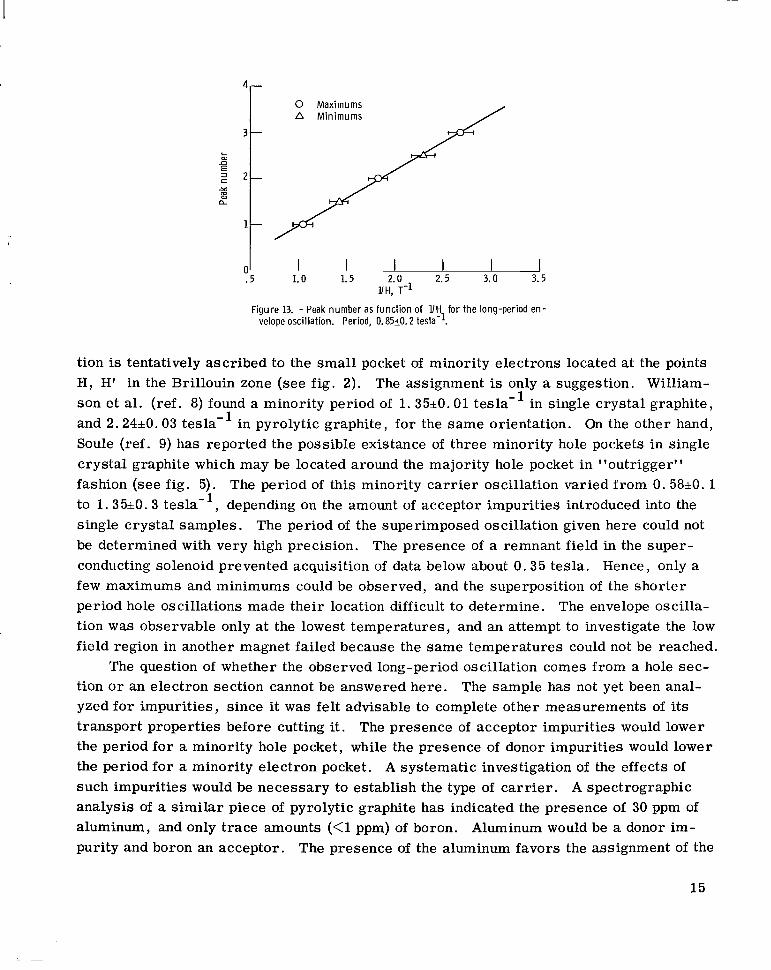
L al n
3 c r m al a
E
4
2 1 1
n I I I I I I .5 1.0 1.5 2.0 2.5 3.0 3.5
UH, T - l
Figure 13. - Peak number as function of UH for t h e long-period en- velope oscillation. Period, 0.8520.2 tesla-'.
tion is tentatively ascribed to the small pocket of minority electrons located at the points H, H' in the Brillouin zone (see fig. 2). The assignment is only a suggestion. William- son et al. (ref. 8) found a minority period of 1.35*0.01 tesla-' in single crystal graphite, and 2.24k0.03 tesla-' in pyrolytic graphite, for the same orientation. On the other hand, Soule (ref. 9) has reported the possible existance of three minority hole pockets in single crystal graphite which may be located around the majority hole pocket in "outrigger" fashion (see fig. 5). to 1.35*0.3 tesla-', depending on the amount of acceptor impurities introduced into the single crystal samples. The period of the superimposed oscillation given here could not be determined with very high precision. The presence of a remnant field in the super- conducting solenoid prevented acquisition of data below about 0 .35 tesla. Hence, only a few maximums and minimums could be observed, and the superposition of the shorter period hole oscillations made their location difficult to determine. tion was observable only a t the lowest temperatures, and an attempt to investigate the low field region in another magnet failed because the same temperatures could not be reached.
tion or an electron section cannot be answered here. The sample has not yet been anal- yzed for impurities, since it was felt advisable to complete other measurements of i ts transport properties before cutting it. The presence of acceptor impurities would lower the period for a minority hole pocket, while the presence of donor impurities would lower the period for a minority electron pocket. A systematic investigation of the effects of such impurities would be necessary to establish the type of car r ie r . A spectrographic analysis of a s imilar piece of pyrolytic graphite has indicated the presence of 30 ppm of aluminum, and only trace amounts (<1 ppm) of boron. Aluminum would be a donor im- purity and boron an acceptor. The presence of the aluminum favors the assignment of the
The period of this minority car r ie r oscillation varied from 0. 58*0. 1
The envelope oscilla-
The question of whether the observed long-period oscillation comes from a hole sec-
15

oscillation to the minority electron pocket, since the samples were presumably prepared under the same conditions. The majority volumes a r e relatively unaffected by small im- purity concentrations.
Figure 14 shows a recorder t race of dT/dH as a function of H up to 8 tesla. The
dVldH
I I I I I I I I 1 2 3 4 5 6 7 8
Figure 14. - Recorder trace of magnetothermal oscillations. 8 = 17' from c-axis; tempera-
Magnetic f ield strength, H, T 0'-
ture, 1.4 K.
magnetic field is tilted 17' from the c-axis. The figure clearly indicates how quickly the low quantum number regime is reached for the hole oscillations. The waveform is begin- ning to show some distortion by about 1 .0 tesla, and is definitely nonsinusoidal for fields above 2 tesla. The frequency of the oscillations in figure 14 is 6.95*0.20 tesla. Since the peaks in the figure actually correspond to maximums in dV/dH, where V is the voltage across the thermometer, they a r e shifted from the maximums in dT/dH by 180'. (Resistance as a function of temperature has a negative slope.) The condition for the occurrence of the nth maximum is therefore
- - 2n-f any - - a = 2nn - - n H 4 2
Table I l ists the peak positions predicted by equation (10) and the fields at which they were actually observed. Equation (10) is not expected to be valid in the so-called quantum limit. The agreement between observed and predicted maximums is within experimental e r r o r for fields up to 2 tesla.
A plot of n as a function of 1/H for the field parallel to the c-axis is shown in fig- ure 15. The integers were assigned to the peaks on the basis of the preceding discussion. The intercept may be used to calculate the quantity y in equation (10). From the figure, the intercept of the line is n = -0.37*0.10. Inserting this in equation (10) gives y = 0.5tO.l .
16
I.. I 11.1 I I I I111 I I

TABLE I. - COMPARISON OF PREDICTED FIELD
POSITIONS OF MAXIMUMS IN dV/dH
WITH OBSERVED FIELD POSITIONS
Peak number,
1 2 3 4 5 6 7 8 9 10 11 12
g 8
4 6F
Field position, T ~ _ _ _
Predicted
5.06 2.93 2.06 1.59 1.29 1.09 9.43 8. 30 7.42 6.70 6. 12 5.62
___
Observed
7.810. 02 3.210. 02
2.05+0.02 1. 5410.02 1.2710. 02 1.0810. 02 9.30+0.02 8.2010. 02 7.5010.02 6.60iO. 02 6.1010. 02 5.60+0.02
/\ Slope = 6.6f0.26 T
0 21/ _- -Intercept = -0.37
I 0
-2 2 1- 3
I 1
UH, T - l
Figure 15. - Peak number as funct ion of UH for hole osci l lat ions wi th H along c-axis.
17
I
CONCLUSION S
The periodicity in 1/H of the oscillatory variations in temperature of the sample of pressure-annealed, pyrolytic graphite used in these experiments agrees well with that obtained for hole ca r r i e r s by other workers in both single crystal and pyrolytic graphite. The measured value of the hole period for H parallel to the c-axis was 0.151*0.005 tesla- . From observations into the quantum limit, the phase factor y was found to be 0.5*0.10.
A long-period oscillation was also observed which is tentatively ascribed to the min- ority electron pocket occurring at the corners of the Brillouin zone. The period of this oscillation was estimated to be 0.85k0.20 tesla-' and is not in good agreement with other published values for these ca r r i e r s . One explanation for the different minority period observed in this study is the possible presence of donor impurities in the sample. An analysis of a s imilar piece of pyrolytic graphite has indicated the presence of 30 ppm of aluminum and tends to corroborate this suspicion. Small t races of impurities could greatly affect the dimensions of the small pockets of minority ca r r i e r s , while hardly af- fecting the majority ca r r i e r volumes.
1
Lewis Research Center, National Aeronautics and Space Administration,
Cleveland, Ohio, August 5, 1969, 129-02.
18

APPENDIX - SYMBOLS
A symmetry point in hexagonal face of Brillouin zone
A(EF) cross-sectional a r e a of Fermi surface
a rea enclosed by orbit of electrons in state labeled by quantum number n An Ao(EF) extremal cross-sectional a r e a of Fermi surface
a cross-sectional a r e a of thermal path from sample to heat reservoir
cH
cO
EF
En
E2
E3
C
f
g
H
H7 H'
h7 fi
K
K, K'
kg
kO
kx kY kZ
L
M
Most
specific heat at constant magnetic field
speed of light in vacuum
twice the interplanar separation along the c-axis of graphite
Fermi energy
energy level of f ree electrons in a magnetic field
electronic energy band in graphite
electronic energy band in graphite
electronic energy band in graphite
de Haas - van Alphen frequency of oscillations periodic in 1/H
effective spin-splitting factor for electrons in a magnetic field
magnetic field strength
symmetry points along zone edges of hexagonal Brillouin zone
Planck's constant (divided by 27r)
thermal conductivity of thermal path from sample to heat reservoir
symmetry points at center of zone edges of hexagonal Brillouin zone
Bo ltzmann constant
value of kz at extremal a rea of Fermi surface
x-component of wave vector of electron
y-component of wave vector of electron
z-component of wave vector of electron
length of thermal path from sample to heat reservoir
magnetization of a system of conduction electrons
oscillatory component of magnetization of system of conduction electrons
19
I

mO
m*
n
Q
R300
R4. 2 S
T
TH U
V
W
X
Y
r K
7D w*
20
free electron mass
cyclotron effective mass of electron in a magnetic field
quantum number labeling the energy level of an electron in a magnetic field
heat adsorbed or released by a thermodynamic system
sample resistance at room temperature
sample resistance in liquid helium
entropy of the rmo d ynam i c system
absolute temperature of thermodynamic system
' 'magnetic temperature" defined by eq. (5b)
internal energy of thermodynamic system
volume of system of conduction electrons
work done by o r on a thermodynamic system
Dingle temperature
phase factor in energy dispersion relation of electrons in a magnetic field
symmetry point at center of hexagonal Brillouin zone
heat per second per degree transported along thermal path from sample to reservoir
average between collisions for an electron in a solid
cyclotron frequency of electrons in a magnetic field
I Y
REFERENCES
1. Kunzler, J. E . ; Hsu, F. S. L . ; and Boyle, W. S.: Magnetothermal Oscillations. The Oscillatory Dependence of Temperature on Magnetic Field. Phys. Rev. , vol. 128, no. 3, Nov. 1, 1962, pp. 1084-1098.
2 . LePage, J. ; Garber, M. ; and Blatt, F. J. : Magnetothermal Oscillations in Beryl- lium. Low Temperature Physics - LT9. Part B. J. G. Daunt, D. 0. Edwards, F. J. Milford, andM. Yaqub, eds . , Plenum Press, Inc., 1965, p. 799.
i r' 3. McCombe, B. D. ; and Seidel, G. : Magnetothermal Oscillations in Semi-Metals. Low Temperature Physics - LT9. Part B. J. G. Daunt, D. 0. Edwards, F. J. Milford, and M. Yaqub, eds. , Plenum Press, Jnc. , 1965, p. 794.
4 . McCombe, B. D. ; Broshar, W. ; and Seidel, G. : Magnetic Oscillations in Beryllium. Bull. Am. Phys. SOC., vol. 11, no. 1, Jan. 1966, p. 91.
5. McCombe, B. ; and Seidel, G. : Magnetothermal Oscillations and Spin Splitting in Bismuth and Antimony. Phys. Rev. , vol. 155, no. 3, Mar. 15, 1967, pp. 633-641.
6 . Klein, C. A. ; Straub, W. D. ; and Diefendorf, R. J. : Evidence of Single-Crystal Characteristics of Highly Annealed Pyrolytic Graphite. Phys. Rev. , vol. 125, no. 2 , Jan. 15, 1962, pp. 468-470.
7 . Klein, Claude A. : Electrical Properties of Pyrolytic Graphites. Rev. Mod. Phys. , vol. 34, no. 1, Jan. 1962, pp. 56-79.
8. Williamson, S. J. ; Foner, S. ; and Dresselhaus, M. S . : de Haas-van Alphen Effect in Pyrolytic and Single-Crystal Graphite. Phys. Rev. , vol. 140A, no. 4 , Nov. 15, 1962, pp. 1429- 1447.
9 . Soule, D. E. : Change in Fermi Surfaces of Graphite by Dilute Acceptor Doping. IBM J. Res. Dev. , vol. 8, no. 3, July 1964, pp. 268-273.
10. Soule, D. E . ; McClure, J. W . ; and Smith, L. B. : Study of the Shubnikov-de Haas Effect Determination of the Fermi Surfaces in Graphite. Phys. Rev. , vol. 134A, no. 2 , Apr. 20, 1964, pp. 453-470.
11. Slonczewski, J. C. ; and Weiss, P. R. : Band Structure of Graphite. Phys. Rev. , vol. 109, no. 2 , Jan. 15, 1958, pp. 272-279.
12. Lifshitz, I. M. ; and Kosevich, A. M. : Theory of Magnetic Susceptibility in Metals a t Low Temperatures. Soviet Phys.-JETP, vol. 2 , no. 4 , July 1956, pp. 636-645.
13. Cohen, M. H. ; and Blount, E. I. : The g-factor and de Haas-van Alphen Effect of Electrons in Bismuth. Phil. Mag. , vol. 5, no. 50, Feb. 1960, pp. 115-126.
21
I 14. Dingle, R. B. : Some Magnetic Properties of Metals. II. The Influence of Colli- ~
I
I sions on the Magnetic Behaviour of Large Systems. Proc . Roy. SOC. (London), Ser . A, vol. 211, no. 1107, Mar. 20, 1952, pp. 517-525.
15. Williamson, S. J. ; Foner, S. ; and Smith, R. A. : Influence of Landau Level Broad- I
ening on the de Haas-van Alphen Effect. Phys. Rev. , vol. 136A, no. 4, Nov. 16,
1964, pp. 1065-1067. I
I 16. Onsager, L. : Interpretation of the de Haas-van Alphen Effect. Phil. Mag., vol. 43, no. 344, Sept. 1952, pp. 1006-1008.
! 17. Chambers, R. G. : The Wave Function of a Block Electron in a Magnetic Field.
Proc. Phys. SOC. (London), vol. 89, pt. 3, Nov. 1966, pp. 695-710. f
18. McClure, J. W. : Theory of Diamagnetism of Graphite. Phys. Rev., vol. 119, no. 2, July 15, 1960, pp. 606-613.
NASA-Langley, 1969 - 26 E- 5032