m19 hald6891 06 se ch19 -...
TRANSCRIPT

# 101145 C t PH OH CHET A H ld P N 324 K/PMS DESIGN SERVICES OF
After studying Chapter 19, the reader will be able to:
1. Prepare for ASE Engine Performance (A8) certification test content
area “C” (Fuel, Air Induction, and Exhaust Systems Diagnosis and
Repair).
Bar (p. 326)
Boost (p. 326)
Bypass Valve (p. 328)
Compressor Bypass Valve (CBV) (p. 332)
Dry System (p. 334)
Dump Valve (p. 332)
Intercooler (p. 330)
Naturally (normally) Aspirated (p. 326)
Nitrous Oxide (p. 333)
Positive Displacement (p. 327)
CHAPTER 19
TURBOCHARGING
AND SUPERCHARGING
TURBOCHARGING
AND SUPERCHARGING
2. Explain the difference between a turbocharger and a supercharger.
3. Describe how the boost levels are controlled.
4. Discuss maintenance procedures for turbochargers and
superchargers.
Power Adder (p. 333)
Relief Valve (p. 332)
Roots-Type Supercharger (p. 327)
Supercharger (p. 326)
Turbo Lag (p. 330)
Turbocharger (p. 328)
Vent Valve (p. 332)
Volumetric Efficiency (p. 325)
Wastegate (p. 331)
Wet System (p. 334)
OBJECTIVES
KEY TERMS
M19_HALD6891_06_SE_CH19.QXD 6/11/08 10:55 AM Page 324

Turbocharging and Supercharging 325
# 101145 C t PH OH CHET A H ld P N 325 K/PMS DESIGN SERVICES OF
FIGURE 19-1 A supercharger on a Ford V-8.
FIGURE 19-2 A turbocharger on a Toyota engine.
AIRFLOW REQUIREMENTS
Naturally aspirated engines with throttle bodies rely on atmo-spheric pressure to push an air–fuel mixture into the combus-tion chamber vacuum created by the downstroke of a piston.The mixture is then compressed before ignition to increasethe force of the burning, expanding gases. The greater themixture compression, the greater the power resulting fromcombustion.
All gasoline automobile engines share certain air–fuelrequirements. For example, a four-stroke engine can take inonly so much air, and how much fuel it consumes depends onhow much air it takes in. Engineers calculate engine airflowrequirements using these three factors:
■ Engine displacement■ Engine revolutions per minute (RPM)■ Volumetric efficiency
Volumetric Efficiency
Volumetric efficiency is a comparison of the actual volumeof air–fuel mixture drawn into an engine to the theoreticalmaximum volume that could be drawn in. Volumetric effi-ciency is expressed as a percentage, and changes with enginespeed. For example, an engine might have 75% volumetricefficiency at 1000 RPM. The same engine might be rated at85% at 2000 RPM and 60% at 3000 RPM.
If the engine takes in the airflow volume slowly, a cylin-der might fill to capacity. It takes a definite amount of time forthe airflow to pass through all the curves of the intake mani-fold and valve port. Therefore, volumetric efficiency decreasesas engine speed increases. At high speed, it may drop to as lowas 50%.
The average street engine never reaches 100% volumet-ric efficiency. With a street engine, the volumetric efficiency isabout 75% at maximum speed, or 80% at the torque peak. Ahigh-performance street engine is about 85% efficient, or a bitmore efficient at peak torque. A race engine usually has 95%or better volumetric efficiency. These figures apply only to nat-urally aspirated engines, however, and turbocharged and su-percharged engines easily achieve more than 100% volumetricefficiency. Many vehicles are equipped with a supercharger ora turbocharger to increase power. See Figures 19-1 and 19-2.
Engine Compression
Higher compression increases the thermal efficiency of the en-gine because it raises compression temperatures, resulting inhotter, more complete combustion. However, a higher com-pression can cause an increase in NOX emissions and wouldrequire the use of high-octane gasoline with effective anti-knock additives.
SUPERCHARGING
PRINCIPLES
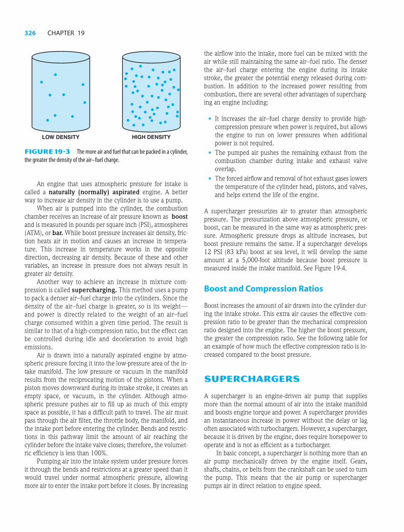
The amount of force an air–fuel charge produces when it isignited is largely a function of the charge density. Density isthe mass of a substance in a given amount of space. SeeFigure 19-3.
The greater the density of an air–fuel charge forced into acylinder, the greater the force it produces when ignited, andthe greater the engine power.
M19_HALD6891_06_SE_CH19.QXD 6/10/08 3:35 AM Page 325
326 CHAPTER 19
# 101145 C t PH OH CHET A H ld P N 326 K/PMS DESIGN SERVICES OF
LOW DENSITY HIGH DENSITY
FIGURE 19-3 The more air and fuel that can be packed in a cylinder,the greater the density of the air–fuel charge.
An engine that uses atmospheric pressure for intake iscalled a naturally (normally) aspirated engine. A betterway to increase air density in the cylinder is to use a pump.
When air is pumped into the cylinder, the combustionchamber receives an increase of air pressure known as boostand is measured in pounds per square inch (PSI), atmospheres(ATM), or bar. While boost pressure increases air density, fric-tion heats air in motion and causes an increase in tempera-ture. This increase in temperature works in the oppositedirection, decreasing air density. Because of these and othervariables, an increase in pressure does not always result ingreater air density.
Another way to achieve an increase in mixture com-pression is called supercharging. This method uses a pumpto pack a denser air–fuel charge into the cylinders. Since thedensity of the air–fuel charge is greater, so is its weight—and power is directly related to the weight of an air–fuelcharge consumed within a given time period. The result issimilar to that of a high-compression ratio, but the effect canbe controlled during idle and deceleration to avoid highemissions.
Air is drawn into a naturally aspirated engine by atmo-spheric pressure forcing it into the low-pressure area of the in-take manifold. The low pressure or vacuum in the manifoldresults from the reciprocating motion of the pistons. When apiston moves downward during its intake stroke, it creates anempty space, or vacuum, in the cylinder. Although atmo-spheric pressure pushes air to fill up as much of this emptyspace as possible, it has a difficult path to travel. The air mustpass through the air filter, the throttle body, the manifold, andthe intake port before entering the cylinder. Bends and restric-tions in this pathway limit the amount of air reaching thecylinder before the intake valve closes; therefore, the volumet-ric efficiency is less than 100%.
Pumping air into the intake system under pressure forcesit through the bends and restrictions at a greater speed than itwould travel under normal atmospheric pressure, allowingmore air to enter the intake port before it closes. By increasing
the airflow into the intake, more fuel can be mixed with theair while still maintaining the same air–fuel ratio. The denserthe air–fuel charge entering the engine during its intakestroke, the greater the potential energy released during com-bustion. In addition to the increased power resulting fromcombustion, there are several other advantages of supercharg-ing an engine including:
■ It increases the air–fuel charge density to provide high-compression pressure when power is required, but allowsthe engine to run on lower pressures when additionalpower is not required.
■ The pumped air pushes the remaining exhaust from thecombustion chamber during intake and exhaust valveoverlap.
■ The forced airflow and removal of hot exhaust gases lowersthe temperature of the cylinder head, pistons, and valves,and helps extend the life of the engine.
A supercharger pressurizes air to greater than atmosphericpressure. The pressurization above atmospheric pressure, orboost, can be measured in the same way as atmospheric pres-sure. Atmospheric pressure drops as altitude increases, butboost pressure remains the same. If a supercharger develops12 PSI (83 kPa) boost at sea level, it will develop the sameamount at a 5,000-foot altitude because boost pressure ismeasured inside the intake manifold. See Figure 19-4.
Boost and Compression Ratios
Boost increases the amount of air drawn into the cylinder dur-ing the intake stroke. This extra air causes the effective com-pression ratio to be greater than the mechanical compressionratio designed into the engine. The higher the boost pressure,the greater the compression ratio. See the following table foran example of how much the effective compression ratio is in-creased compared to the boost pressure.
SUPERCHARGERS
A supercharger is an engine-driven air pump that suppliesmore than the normal amount of air into the intake manifoldand boosts engine torque and power. A supercharger providesan instantaneous increase in power without the delay or lagoften associated with turbochargers. However, a supercharger,because it is driven by the engine, does require horsepower tooperate and is not as efficient as a turbocharger.
In basic concept, a supercharger is nothing more than anair pump mechanically driven by the engine itself. Gears,shafts, chains, or belts from the crankshaft can be used to turnthe pump. This means that the air pump or superchargerpumps air in direct relation to engine speed.
M19_HALD6891_06_SE_CH19.QXD 6/10/08 3:35 AM Page 326

Turbocharging and Supercharging 327
# 101145 C t PH OH CHET A H ld P N 327 K/PMS DESIGN SERVICES OF
There are two general types of superchargers:
■ Roots-type supercharger. Named for Philander andFrancis Roots, two brothers from Connersville, Indiana,who patented the design in 1860 as a type of water pumpto be used in mines. Later it was used to move air and isused today on two-stroke cycle Detroit diesel engines andother supercharged engines. The roots-type super-charger is called a positive displacement design becauseall of the air that enters is forced through the unit. Exam-ples of a roots-type supercharger include the GMC 6-71(used originally on GMC diesel engines that had six cylin-ders each with 71 cu. in.) and Eaton used on supercharged3800 V-6 General Motors engines. See Figure 19-5.
■ Centrifugal supercharger. A centrifugal supercharger issimilar to a turbocharger but is mechanically driven by theengine instead of being powered by the hot exhaust gases.A centrifugal supercharger is not a positive displacement
pump and all of the air that enters is not forced throughthe unit. Air enters a centrifugal supercharger housing inthe center and exits at the outer edges of the compressorwheels at a much higher speed due to centrifugal force.The speed of the blades has to be higher than engine speed
LOBE
NEW YORK CITY14.7 PSI
ST. LOUIS(600 FT.)14.4 PSI
DENVER(5000 FT.)13.0 PSI
PIKES PEAK(14,000 FT.)8.6 PSI
FIGURE 19-4 Atmospheric pressure decreases with increases in altitude.
Final Compression Ratio Chart at Various Boost LevelsBlower Boost (PSI)
Comp Ratio 2 4 6 8 10 12 14 16 18 206.5 7.4 8.3 9.2 10 10.9 11.8 12.7 13.6 14.5 15.37 8 8.9 9.9 10.8 11.8 12.7 13.6 14.5 15.3 16.27.5 8.5 9.5 10.6 11.6 12.6 13.6 14.6 15.7 16.7 17.88 9.1 10.2 11.3 12.4 13.4 14.5 15.6 16.7 17.8 18.98.5 9.7 10.8 12 13.1 14.3 15.4 16.6 17.8 18.9 19.89 10.2 11.4 12.7 13.9 15.1 16.3 17.6 18.8 20 21.29.5 10.8 12.1 13.4 14.7 16 17.3 18.5 19.8 21.1 22.4
10 11.4 12.7 14.1 15.4 16.8 18.2 19.5 20.9 22.2 23.6
FIGURE 19-5 A roots-type supercharger uses two lobes to force theair around the outside of the housing into the intake manifold.
M19_HALD6891_06_SE_CH19.QXD 6/10/08 3:35 AM Page 327

328 CHAPTER 19
# 101145 C t PH OH CHET A H ld P N 328 K/PMS DESIGN SERVICES OF
DRIVE PULLEY
SUPERCHARGER
LOWER INTAKEPLEUM
BYPASS ACTUATOR
TO VACUUM SOURCE (CONTROLLED BY THE COMPUTER)
BYPASS VALVE
THROTTLE BODY
FIGURE 19-6 The bypass actuator opens the bypass valve to control boost pressure.
FUEL IN100%
EXHAUSTOUT 50%
POWEROUT 25%
RADIATORCOOLING25%
so a smaller pulley is used on the supercharger and thecrankshaft overdrives the impeller through an internalgear box achieving about seven times the speed of the en-gine. Examples of centrifugal superchargers includeVortech and Paxton.
Supercharger Boost Control
Many factory-installed superchargers are equipped with abypass valve that allows intake air to flow directly into theintake manifold bypassing the supercharger. The computercontrols the bypass valve actuator. See Figure 19-6.
The airflow is directed around the supercharger when-ever any of the following conditions occur:
■ The boost pressure, as measured by the MAP sensor, indi-cates that the intake manifold pressure is reaching the pre-determined boost level.
■ During deceleration.■ Whenever reverse gear is selected.
Supercharger Service
Superchargers are usually lubricated with synthetic engine oilinside the unit. This oil level should be checked and replacedas specified by the vehicle or supercharger manufacturer. Thedrive belt should also be inspected and replaced as necessary.
TURBOCHARGERS
The major disadvantage of a supercharger is its reliance on en-gine power to drive the unit. In some installations, as much as20% of the engine’s power is used by a mechanical super-charger. However, by connecting a centrifugal supercharger to
a turbine drive wheel and installing it in the exhaust path, thelost engine horsepower is regained to perform other work andthe combustion heat energy lost in the engine exhaust (asmuch as 40% to 50%) can be harnessed to do useful work.This is the concept of a turbocharger.
The turbocharger’s main advantage over a mechanicallydriven supercharger is that the turbocharger does not drainpower from the engine. In a naturally aspirated engine, abouthalf of the heat energy contained in the fuel goes out the ex-haust system. See Figure 19-7. Another 25% is lost through ra-diator cooling. Only about 25% is actually converted tomechanical power. A mechanically driven pump uses some ofthis mechanical output, but a turbocharger gets its energyfrom the exhaust gases, converting more of the fuel’s heat en-ergy into mechanical energy.
A turbocharger turbine looks much like a typical cen-trifugal pump used for supercharging. See Figure 19-8.Hot exhaust gases flow from the combustion chamber to theturbine wheel. The gases are heated and expanded as theyleave the engine. It is not the speed of force of the exhaustgases that forces the turbine wheel to turn, as is commonly
FIGURE 19-7 A turbocharger uses some of the heat energy thatwould normally be wasted.
M19_HALD6891_06_SE_CH19.QXD 6/10/08 3:35 AM Page 328

Turbocharging and Supercharging 329
# 101145 C t PH OH CHET A H ld P N 329 K/PMS DESIGN SERVICES OF
EXHAUST
EXHAUST
FIGURE 19-8 A turbine wheel is turned by the expanding exhaustgases.
thought, but the expansion of hot gases against the turbinewheel’s blades.
Turbocharger Design and Operation
A turbocharger consists of two chambers connected by a cen-ter housing. The two chambers contain a turbine wheel and acompressor wheel connected by a shaft which passes throughthe center housing.
To take full advantage of the exhaust heat which providesthe rotating force, a turbocharger must be positioned as closeas possible to the exhaust manifold. This allows the hot ex-haust to pass directly into the unit with a minimum of heatloss. As exhaust gas enters the turbocharger, it rotates the tur-bine blades. The turbine wheel and compressor wheel are onthe same shaft so that they turn at the same speed. Rotation ofthe compressor wheel draws air in through a central inlet andcentrifugal force pumps it through an outlet at the edge of thehousing. A pair of bearings in the center housing support theturbine and compressor wheel shaft, and are lubricated by en-gine oil. See Figure 19-9.
Both the turbine and compressor wheels must operatewith extremely close clearances to minimize possible leakagearound their blades. Any leakage around the turbine bladescauses a dissipation of the heat energy required for compres-sor rotation. Leakage around the compressor blades preventsthe turbocharger from developing its full boost pressure.
When the engine is started and runs at low speed, bothexhaust heat and pressure are low and the turbine runs at alow speed (approximately 1000 RPM). Because the compres-sor does not turn fast enough to develop boost pressure, airsimply passes through it and the engine works like any naturally
aspirated engine. As the engine runs faster or load increases,both exhaust heat and flow increases, causing the turbine andcompressor wheels to rotate faster. Since there is no brake andvery little rotating resistance on the turbocharger shaft, the tur-bine and compressor wheels accelerate as the exhaust heat en-ergy increases. When an engine is running at full power, thetypical turbocharger rotates at speeds between 100,000 and150,000 RPM.
Engine deceleration from full power to idle requires onlya second or two because of its internal friction, pumping resist-ance, and drivetrain load. The turbocharger, however, has nosuch load on its shaft, and is already turning many times fasterthan the engine at top speed. As a result, it can take as muchas a minute or more after the engine has returned to idle speedbefore the turbocharger also has returned to idle. If the engineis decelerated to idle and then shut off immediately, engine lu-brication stops flowing to the center housing bearings whilethe turbocharger is still spinning at thousands of RPM. The oilin the center housing is then subjected to extreme heat andcan gradually “coke” or oxidize. The coked oil can clog pas-sages and will reduce the life of the turbocharger.
The high rotating speeds and extremely close clearancesof the turbine and compressor wheels in their housings requireequally critical bearing clearances. The bearings must keep ra-dial clearances of 0.003 to 0.006 inch (0.08 to 0.15 mm). Ax-ial clearance (end play) must be maintained at 0.001 to 0.003inch (0.025 to 0.08 mm). If properly maintained, the tur-bocharger also is a trouble-free device. However, to preventproblems, the following conditions must be met:
■ The turbocharger bearings must be constantly lubricatedwith clean engine oil—turbocharged engines should haveregular oil changes at half the time or mileage intervalsspecified for nonturbocharged engines.
FIGURE 19-9 The exhaust drives the turbine wheel on the left,which is connected to the impeller wheel on the right through a shaft.The bush-ings that support the shaft are lubricated with engine oil under pressure.
M19_HALD6891_06_SE_CH19.QXD 6/10/08 3:35 AM Page 329

330 CHAPTER 19
# 101145 C t PH OH CHET A H ld P N 330 K/PMS DESIGN SERVICES OF
■ Dirt particles and other contamination must be kept out ofthe intake and exhaust housings.
■ Whenever a basic engine bearing (crankshaft or camshaft)has been damaged, the turbocharger must be flushed withclean engine oil after the bearing has been replaced.
■ If the turbocharger is damaged, the engine oil must bedrained and flushed and the oil filter replaced as part ofthe repair procedure.
Late-model turbochargers all have liquid-cooled center bearingsto prevent heat damage. In a liquid-cooled turbocharger, enginecoolant is circulated through passages cast in the center housingto draw off the excess heat. This allows the bearings to run coolerand minimize the probability of oil coking when the engine isshut down.
Turbocharger Sizeand Response Time
A time lag occurs between an increase in engine speed and theincrease in the speed of the turbocharger. This delay betweenacceleration and turbo boost is called turbo lag. Like any ma-terial, moving exhaust gas has inertia. Inertia also is present inthe turbine and compressor wheels, as well as the intake air-flow. Unlike a supercharger, the turbocharger cannot supplyan adequate amount of boost at low speed.
Turbocharger response time is directly related to the sizeof the turbine and compressor wheels. Small wheels acceler-ate rapidly; large wheels accelerate slowly. While small wheelswould seem to have an advantage over larger ones, they maynot have enough airflow capacity for an engine. To minimizeturbo lag, the intake and exhaust breathing capacities of anengine must be matched to the exhaust and intake airflowcapabilities of the turbocharger.
BOOST CONTROL
Both supercharged and turbocharged systems are designed toprovide a pressure greater than atmospheric pressure in the in-take manifold. This increased pressure forces additionalamounts of air into the combustion chamber over what wouldnormally be forced in by atmospheric pressure. This increasedcharge increases engine power. The amount of “boost” (orpressure in the intake manifold) is measured in pounds persquare inch (PSI), in inches of mercury (in. Hg), in bars, or inatmospheres. The following values will vary due to altitudeand weather conditions (barometric pressure).
1 atmosphere � 14.7 PSI1 atmosphere � 29.50 in. Hg1 atmosphere � 1.0 bar1 bar � 14.7 PSI
The higher the level of boost (pressure), the greater thehorsepower potential. However, other factors must be consid-ered when increasing boost pressure:
1. As boost pressure increases, the temperature of the airalso increases.
2. As the temperature of the air increases, combustion tem-peratures also increase, which increases the possibility ofdetonation.
3. Power can be increased by cooling the compressed air af-ter it leaves the turbocharger. The power can be in-creased about 1% per 10°F by which the air is cooled. Atypical cooling device is called an intercooler and is sim-ilar to a radiator, wherein outside air can pass through,cooling the pressurized heated air. See Figure 19-10.Some intercoolers use engine coolant to cool the hotcompressed air that flows from the turbocharger to theintake.
4. As boost pressure increases, combustion temperatureand pressures increase, which, if not limited, can dosevere engine damage. The maximum exhaust gastemperature must be 1,550°F (840°C). Higher tempera-tures decrease the durability of the turbocharger and theengine.
Wastegate
A turbocharger uses exhaust gases to increase boost, whichcauses the engine to make more exhaust gases, which in turnincreases the boost from the turbocharger. To prevent overboost
FIGURE 19-10 The unit on top of this Subaru that looks like a radi-ator is the intercooler, which cools the air after it has been compressed by theturbocharger.
M19_HALD6891_06_SE_CH19.QXD 6/10/08 3:35 AM Page 330

Turbocharging and Supercharging 331
# 101145 C t PH OH CHET A H ld P N 331 K/PMS DESIGN SERVICES OF
EXHAUSTSTROKE
BOOST PRESSURE
WASTEGATE(OPEN)
COMPRESSOR
TURBINEEXHAUST
INTAKE
VENT TOAIR CLEANER
IGN.
PCM
WASTEGATECONTROLVALVE (N.C.)
FIGURE 19-11 A wastegate is used on thefirst-generation Duramax diesel to control maximumboost pressure.
and severe engine damage, most turbocharger systems use awastegate. A wastegate is a valve similar to a door that canopen and close. The wastegate is a bypass valve at the exhaustinlet to the turbine. It allows all of the exhaust into the tur-bine, or it can route part of the exhaust past the turbine to theexhaust system. If the valve is closed, all of the exhaust trav-els to the turbocharger. When a predetermined amount ofboost pressure develops in the intake manifold, the wastegatevalve is opened. As the valve opens, most of the exhaust flowsdirectly out the exhaust system, bypassing the turbocharger.With less exhaust flowing across the vanes of the tur-bocharger, the turbocharger decreases in speed and boost pres-sure is reduced. When the boost pressure drops, the wastegatevalve closes to direct the exhaust over the turbocharger vanesand again allow the boost pressure to rise. Wastegate opera-tion is a continuous process to control boost pressure.
The wastegate is the pressure control valve of a turbochargersystem. The wastegate is usually controlled by the onboard com-puter through a boost control solenoid. See Figure 19-11.
The boost pressure of a turbocharger (or supercharger) iscommonly measured in pounds per square inch. If acylinder head is restricted because of small valves andports, the turbocharger will quickly provide boost. Boostresults when the air being forced into the cylinder headscannot flow into the cylinders fast enough and “piles up”in the intake manifold, increasing boost pressure. If anengine had large valves and ports, the turbochargercould provide a much greater amount of air into the en-gine at the same boost pressure as an identical enginewith smaller valves and ports. Therefore, by increasingthe size of the valves, a turbocharged or superchargedengine will be capable of producing much greater power.
TechTipBOOST IS THE
RESULT OF
RESTRICTION
M19_HALD6891_06_SE_CH19.QXD 6/10/08 3:35 AM Page 331

332 CHAPTER 19
# 101145 C t PH OH CHET A H ld P N 332 K/PMS DESIGN SERVICES OF
Relief Valves
A wastegate controls the exhaust side of the turbocharger. Arelief valve controls the intake side. A relief valve vents pres-surized air from the connecting pipe between the outlet of theturbocharger and the throttle whenever the throttle is closedduring boost, such as during shifts. If the pressure is not re-leased, the turbocharger turbine wheel will slow down, creat-ing a lag when the throttle is opened again after a shift has beencompleted. There are two basic types of relief valves including:
■ Compressor bypass valve or CBV This type of reliefvalve routes the pressurized air to the inlet side of the tur-bocharger for reuse and is quiet during operation.
■ Blow-off valve or BOV This is also called a dump valveor vent valve and features an adjustable spring design thatkeeps the valve closed until a sudden release of the throt-tle. The resulting pressure increase opens the valve andvents the pressurized air directly into the atmosphere. Thistype of relief valve is noisy in operation and creates awhooshing sound when the valve opens. See Figure 19-12.
TURBOCHARGER FAILURES
When turbochargers fail to function correctly, a drop in poweris noticed. To restore proper operation, the turbocharger must
be rebuilt, repaired, or replaced. It is not possible to simply re-move the turbocharger, seal any openings, and still maintaindecent driveability. Bearing failure is a common cause of tur-bocharger failure, and replacement bearings are usually onlyavailable to rebuilders. Another common turbocharger prob-lem is excessive and continuous oil consumption resulting
A turbocharger uses the exhaust from the engine to spina turbine, which is connected to an impeller inside a tur-bocharger. This impeller then forces air into the engineunder pressure higher than is normally achieved with-out a turbocharger. The more air that can be forced intoan engine, the greater the power potential. A V-type en-gine has two exhaust manifolds and so two small tur-bochargers can be used to help force greater quantitiesof air into an engine, as shown in Figure 19-13.
TechTipIF ONE IS GOOD,
TWO ARE BETTER
EXHAUSTSTROKE
BOOST PRESSURE
WASTEGATE(CLOSED)
COMPRESSOR
TURBINEEXHAUST
INTAKE
RELIEFVALVE
SPRING
BLOWOFFVALVE
THROTTLE VALVE(CLOSED)
FIGURE 19-12 A blow-off valve is used insome turbocharged systems to relieve boost pressureduring deceleration.
M19_HALD6891_06_SE_CH19.QXD 6/10/08 3:35 AM Page 332

Turbocharging and Supercharging 333
in blue exhaust smoke. Turbochargers use small rings similar topiston rings on the shaft to prevent exhaust (combustion gases)from entering the central bearing. Because there are no seals tokeep oil in, excessive oil consumption is usually caused by:
1. A plugged positive crankcase ventilation (PCV) systemresulting in excessive crankcase pressures forcing oil intothe air inlet. This failure is not related to the tur-bocharger, but the turbocharger is often blamed.
2. A clogged air filter, which causes a low-pressure area inthe inlet, which can draw oil past the turbo shaft ringsand into the intake manifold.
3. A clogged oil return (drain) line from the turbocharger tothe oil pan (sump), which can cause the engine oil pres-sure to force oil past the turbocharger’s shaft rings andinto the intake and exhaust manifolds. Obviously, oil be-ing forced into both the intake and exhaust would createlots of smoke.
NITROUS OXIDE (N2O)
Principles
Nitrous oxide is a colorless and nonflammable gas. Nitrousoxide was discovered by a British chemist, Joseph Priestly(1733–1804), who also discovered oxygen. He found that ni-trous oxide caused a person to be light-headed when it wasbreathed and soon became known as laughing gas. Nitrousoxide was used in dentistry during tooth extraction to reducethe pain or at least make the patient forget what occurred.
Nitrous oxide has two nitrogen atoms and one oxideatom. About 36% of the molecule weight is oxygen. Nitrous
oxide is a manufactured gas because, even though both nitro-gen and oxygen are present in our atmosphere, they are notcombined into one molecule and require heat and a catalyst tobe combined.
Engine Power Adder
A power adder is a device or system added to an engine suchas a supercharger, turbocharger, or nitrous oxide to increasepower. When nitrous oxide is injected into an engine alongwith gasoline, engine power is increased. The addition of N2Osupplies the needed oxygen for the extra fuel. By itself, N2Odoes not burn, but rather provides the oxygen for additionalfuel that is supplied along with the N2O to produce more power.
NOTE: Nitrous oxide was used as a power adder in World War II on some
fighter aircraft. Having several hundred more horsepower for a short time
saved many lives.
Pressure and Temperature
It requires about 11 pounds of pressure per degree Fahrenheitto condense nitrous oxide gas into liquid nitrous oxide. Forexample, at 70°F it requires a pressure of about 770 PSI tocondense N2O into a liquid. To change N2O from a liquid un-der pressure to a gas, all that is needed is to lower its pressurebelow the pressure it takes to cause it to become a liquid.
The temperature also affects the pressure of N2O. See thefollowing chart.
Temperature (°F/°C) Pressure (PSI/kPa)
�30°F/�34°C 67 PSI/468 kpa
�20°F/�29°C 203 PSI/1,400 kpa
�10°F/�23°C 240 PSI/1,655 kpa
0°F/�18°C 283 PSI/1,950 kpa
10°F/�12°C 335 PSI/2,310 kpa
20°F/�7°C 387 PSI/2,668 kpa
30°F/�1°C 460 PSI/3,172 kpa
40°F/4°C 520 PSI/3,585 kpa
50°F/10°C 590 PSI/4,068 kpa
60°F/16°C 675 PSI/4,654 kpa
70°F/21°C 760 PSI/5,240 kpa
80°F/27°C 865 PSI/5,964 kpa
90°F/32°C 985 PSI/6,792 kpa
100°F/38°C 1,120 PSI/7,722 kpa
# 101145 C t PH OH CHET A H ld P N 333 K/PMS DESIGN SERVICES OF
FIGURE 19-13 A dual turbocharger system installed on a small blockChevrolet V-8 engine.
Nitrous oxide is stored in a pressurized storage containerand installed at an angle so the pickup tube is in the liquid. The
M19_HALD6891_06_SE_CH19.QXD 6/10/08 3:35 AM Page 333

334 CHAPTER 19
# 101145 C t PH OH CHET A H ld P N 334 K/PMS DESIGN SERVICES OF
LIQUIDN2O
THISSIDEUP
FRONT OF VEHICLE
front of the discharge end of the storage bottle should be to-ward the front of the vehicle. See Figure 19-14.
Wet and Dry Systems
There are two different types of N2O system that depend onwhether additional fuel (gasoline) is supplied at the sametime as when the nitrous oxide is squirted. If additional fuelis also injected, this type of system is called a wet system.A wet system is identified as having both a red and a bluenozzle with the red flowing gasoline and the blue flowingnitrous oxide. In a system such as an engine using port fuelinjection, only nitrous oxide needs to be injected because thePCM can be commanded to provide more fuel when theN2O is being sprayed. As a result, the intake manifold con-tains only air and the injected gaseous N2O, which is calleda dry system.
Engine Changes Needed for N2O
If nitrous oxide is going to be used to increase horsepowermore than 50 hp, the engine must be designed and built towithstand the greater heat and pressure that will occur in thecombustion chambers. For example, the following itemsshould be considered if adding a turbocharger, supercharger,or nitrous oxide system:
■ Forged pistons are best able to withstand the pressureand temperature when using nitrous oxide or an otherpower adder.
■ Cylinder-to-wall clearance should be increased. Due to thegreater amount of heat created by the extra fuel and N2Oinjection, the piston temperature will be increased. Whileusing forged pistons will help, most experts recommendusing increased cylinder-to-wall clearance. Check the in-structions from the nitrous oxide supplier for details andother suggested changes.
FIGURE 19-14 Nitrous bottles have to be mounted at an angle toensure that the pickup tube is in the liquid N2O.
To increase the pressure of the nitrous oxide in a bottle,an electrical warming blanket can be used as seen inFigure 19-15. The higher the temperature, the higherthe pressure and the greater amount of flow of N2O thatwill occur when energized.
TechTipINCREASE BOTTLE
PRESSURE
FIGURE 19-15 An electrical heating mat is installed on the bottle ofnitrous oxide to increase the pressure of the gas inside.
CAUTION: The use of a nitrous oxide injection system can cause cata-
strophic engine damage. Always follow the instructions that come with the
kit and be sure that all of the internal engine parts meet the standard speci-
fied to help avoid severe engine damage.
System Installation and Calibration
Nitrous oxide systems are usually purchased as a kit with all ofthe needed components included. The kit also includes one ormore sizes of nozzle(s), which are calibrated to control the flowof nitrous oxide into the intake manifold. Installation of a ni-trous oxide kit also includes the installation of an on/off switchand a switch on or near the throttle, which is used to activatethe system only at the wide-open throttle (WOT) position.
M19_HALD6891_06_SE_CH19.QXD 6/10/08 3:35 AM Page 334

Turbocharging and Supercharging 335
# 101145 C t PH OH CHET A H ld P N 335 K/PMS DESIGN SERVICES OF
1. What are the reasons why supercharging increases enginepower?
2. How does the bypass valve work on a supercharged engine?
3. What are the advantages and disadvantages of supercharging?
Summary
1. Volumetric efficiency is a comparison of the actual vol-ume of air–fuel mixture drawn into the engine to the the-oretical maximum volume that can be drawn into thecylinder.
2. A supercharger operates from the engine by a drive beltand, while it does consume some engine power, it forcesa greater amount of air into the cylinders for even morepower.
3. A turbocharger uses the normally wasted heat energy ofthe exhaust to turn an impeller at high speed. The im-peller is linked to a turbine wheel on the same shaft andis used to force air into the engine.
4. There are two types of superchargers: roots-type andcentrifugal.
5. A bypass valve is used to control the boost pressure onmost factory-installed superchargers.
6. An intercooler is used on many turbocharged and somesupercharged engines to reduce the temperature of airentering the engine for increased power.
7. A wastegate is used on most turbocharger systems tolimit and control boost pressures, as well as a relief valve,to keep the speed of the turbine wheel from slowingdown during engine deceleration.
8. Nitrous oxide injection can be used as a power adder, butonly with extreme caution.
Review Questions
4. What are the advantages and disadvantages of turbocharging?
5. What turbocharger control valves are needed for proper engineoperation?
Chapter Quiz
1. Boost pressure is generally measured in _____.
a. in. Hg
b. PSI
c. in. H2O
d. in. lb
2. Two types of superchargers include _____.
a. Rotary and reciprocating
b. Roots-type and centrifugal
c. Double and single acting
d. Turbine and piston
3. Which valve is used on a factory supercharger to limit boost?
a. A bypass valve
b. A wastegate
c. A blow-off valve
d. An air valve
4. How are most superchargers lubricated?
a. By engine oil under pressure through lines from the engine
b. By an internal oil reservoir
c. By greased bearings
d. No lubrication is needed because the incoming air cools thesupercharger
5. How are most turbochargers lubricated?
a. By engine oil under pressure through lines from the engine
b. By an internal oil reservoir
c. By greased bearings
d. No lubrication is needed because the incoming air cools thesupercharger
M19_HALD6891_06_SE_CH19.QXD 6/10/08 3:35 AM Page 335

336 CHAPTER 19
# 101145 C t PH OH CHET A H ld P N 336 K/PMS DESIGN SERVICES OF
6. Two technicians are discussing the term “turbo lag.” TechnicianA says that it refers to the delay between when the exhaust leavesthe cylinder and when it contacts the turbine blades of the tur-bocharger. Technician B says that it refers to the delay in boostpressure that occurs when the throttle is first opened. Whichtechnician is correct?
a. Technician A only
b. Technician B only
c. Both Technicians A and B
d. Neither Technician A nor B
7. What is the purpose of an intercooler?
a. To reduce the temperature of the air entering the engine
b. To cool the turbocharger
c. To cool the engine oil on a turbocharged engine
d. To cool the exhaust before it enters the turbocharger
8. Which type of relief valve used on a turbocharged engine isnoisy?
a. A bypass valve
b. A BOV
c. A dump valve
d. Both b and c
9. Technician A says that a stuck-open wastegate can cause the en-gine to burn oil. Technician B says that a clogged PCV systemcan cause the engine to burn oil. Which technician is correct?
a. Technician A only
b. Technician B only
c. Both Technicians A and B
d. Neither Technician A nor B
10. What service operation is most important on engines equippedwith a turbocharger?
a. Replacing the air filter regularly
b. Replacing the fuel filter regularly
c. Regular oil changes
d. Regular exhaust system maintenance
M19_HALD6891_06_SE_CH19.QXD 6/10/08 3:35 AM Page 336