m00-7100v flex probe - opw
TRANSCRIPT
Part Number: M00-7100V, Rev. 0 Issue D ate: September 24, 2015 Supersedes: N/A
6900 Santa Fe Drive • Hodgkins, IL 60525 • Tel: (708) 485-4200 • Fax (708) 485-7237 • www.opwglobal.com
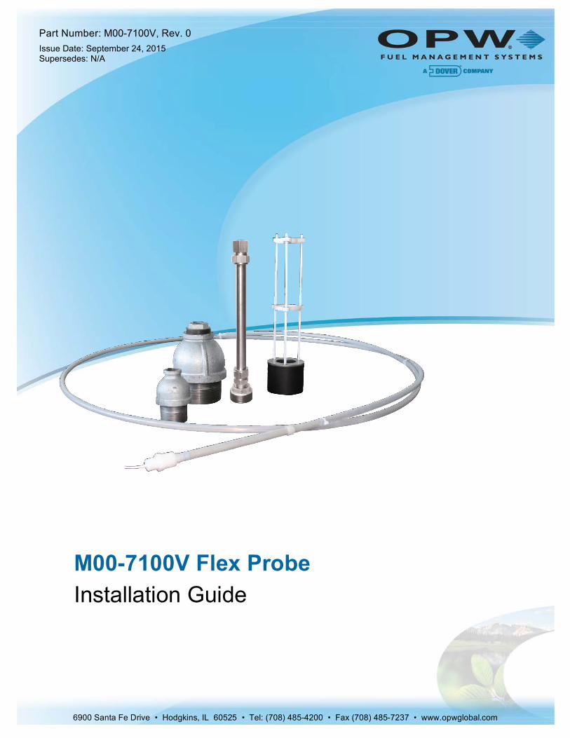
M00-7100V Flex Probe Installation Guide

Doc. No.: M00-7100V, Rev. 0 Page 2 of 17
© Copyright 2014, OPW. Printed in the USA.
© 2014 Delaware Capital Formation, Inc. All Rights Reserved. DOVER and the DOVER logo are registered trademarks of Delaware Capital Formation, Inc., a wholly owned subsidiary of Dover Corporation.
OPW Fuel Management Systems
Visit us at www.opwglobal.com, or contact us at:
Call 1-877-OPW-TECH (877-679-8324) For calls outside US and Canada, call +1-708-485-4200 Fax 1-800-421-3297
Monday through Friday, 7:00 a.m. to 6:00 p.m., U.S. CST
For technician registration, see http://opwglobal.com/TechSupport/TechnicianRegistration.aspx.
For in-depth training via OPW University, see http://www.opwglobal.com/opw-u-training-registration.html
Certifications

Doc. No.: M00-7100V, Rev. 0 Page 3 of 17
Table of Contents M00-7100V Flex Probe Introduction .......................................................................... 4 Section 1
Model 7100V Flex Probe ................................................................................................. 4 1.1
OPW 7100V AST Flex Probe Installation Demonstration ................................................ 4 1.2
Model 7100V Flex Probe Specifications .......................................................................... 5 1.3
Flex Probe Ordering ........................................................................................................ 6 1.4
1.4.1 Flex Probe Determination Worksheet ....................................................................... 6
1.4.2 Flex Probe Length Determination ............................................................................. 7 1.4.3 Flex Probe Float Specifications ................................................................................. 8
Flex Probe Installation ............................................................................................... 9 Section 2
Safety ............................................................................................................................... 9 2.1
2.1.1 Personal Protective Equipment ................................................................................. 9
Flex Probe Installation Preparations ................................................................................ 9 2.2
2.2.1 Flex Probe Wiring .................................................................................................... 10
2.2.2 Installing the Probe in the Tank ............................................................................... 11
2.2.3 Finishing the Flex Probe Installation ....................................................................... 13
Compression Fitting Assembly and Installation ....................................................... 14 Section 3
Warranty ..................................................................................................................................... 16

Doc. No.: M00-7100V, Rev. 0 Page 4 of 17
M00-7100V Flex Probe Introduction Section 1
Model 7100V Flex Probe 1.1
The 7100V Flex Probe utilizes OPW’s industry-leading, field-proven magnetostrictive technology for above ground tanks up to 70 feet (15.2 m) in height.
It is important to follow the handling instructions to avoid damaging the probe and voiding the warranty. During the unpacking and installation of the Model 7100V Flex Probe, always keep the diameter of the coils between 40 and 48 inches (about 1 m).
Flex Probe Installation Requirement:
Flex probe head/wiring must be installed in a weatherproof junction box with seal packs for wiring connections. Failure to comply with these requirements may invalidate probe warranty. See M00-390008, Waterproof Electrical Connections for detailed instructions on assembling the seal packs (the link will take you to the OPWFMS Technical Manuals page on the opwglobal.com website).
OPW 7100V AST Flex Probe Installation Demonstration 1.2
To watch the instructional video OPW 7100V AST Flex Probe Installation Demonstration, scan or click on the QR code below.
The instructional video can also be found at www.YouTube.com by entering the search word “OPWGlobal.”

Doc. No.: M00-7100V, Rev. 0 Page 5 of 17
Model 7100V Flex Probe Specifications 1.3
Flex Probe Specifications
Input Voltage: 23 - 28 VDC
Probe Length: Minimum 12’ to 70’ in one-inch increments
Enclosure Material: PVDF
Rating: IP68
Resolution: 0.010” (0.25 mm) Inventory Mode
Linearity: +/- 0.01% of Full Scale
+/- 0.010” (0.254 mm), whichever is greater
Repeatability: +/- 0.001% of Full Scale
+/- 0.00025” (0.64 mm), whichever is greater
Temp. Accuracy: Absolute +/- 2°F (+/- 1°C)
Temp. Measurement: Up to five (5) along the sensor span;
Resolution: +/- 0.01°F (+/- 0.02°C)
Temp. Sensing: -40°F to +150°F (-40°C to +66°C)
Operating Temp: -40°F to +158°F (-40°C to +70°C)
Environment: NEMA 4-rated
Floats (not included) (refer to Section 11.2 Probe Floats): Specs based on 4” (10.2 cm) standard floats
Listings: UL; Intrinsically Safe; ATEX; IECEx
I.S. Barrier: 24V; OPW P/N: 20-4345
Multi-Drop Capability: Requires one I.S. Barrier channel per probe
Connection: Black and Shield – Ground
Red - Power
Table 1-1 Flex Probe Specifications

Doc. No.: M00-7100V, Rev. 0 Page 6 of 17
Flex Probe Ordering 1.4
Proper operation of the ATG system using the flex probe depends on the correct sizing of the probe. If the probe is too long, it will touch the bottom of the tank and bend, causing either inaccurate or lost readings. If it is too short, product measurement range will be compromised.
1.4.1 Flex Probe Determination Worksheet
Figure 1-1 Flex Probe Determination Worksheet
This form can be found on the OPW web site at http://www.opwglobal.com/.
NOTE: Each Flex Probe is custom made to fit a particular tank. They are not returnable if an error is made in determining the correct length.

Doc. No.: M00-7100V, Rev. 0 Page 7 of 17
1.4.2 Flex Probe Length Determination 1. The flex probe mounts to the tank with a ¾-inch NPT male thread. Obtain the proper fittings to adapt
the tank opening to a ¾-inch NPT female thread.
2. Temporarily install this hardware in the tank opening.
3. Using a plumb bob or measuring tape, measure the distance (in inches) from the top of the ¾-inch NPT flange to the bottom of the tank. Save this measurement. This will be the Total Height (TH).
4. Flex probes are ordered by overall length (OAL). Overall length is the distance from the top of the ¾-inch NPT wiring bushing to the tip of the probe. OAL (inches) = 1.5 + (TH x .993).
o If cable runs to 750 feet (229 m) use Belden #88761
o If cable runs to 1,000 feet (305 m) use Belden #8760, #88760 or #8761
Figure 1-2 Flex Probe Dimensions
NOTE: Do not use the tank’s vent opening to install the flex probe.
NOTE: Some electrical codes require intrinsically safe wiring to have a blue jacket.

Doc. No.: M00-7100V, Rev. 0 Page 8 of 17
Overall Length. Dead Band Tank Bottom Clearance
51” – 144” (130 - 366 cm) 6.00” (15.2 cm) 1.00” (2.5 cm)
145” – 288” (368 - 732 cm) 8.00” (20.3 cm) 2.00” (5.1 cm)
289” – 432” (734 - 1097 cm) 12.00” (30.5 cm) 3.00” (7.6 cm)
433” – 600” (1100 - 1524 cm) 14.00” (35.6 cm) 4.00” (10.2 cm)
601” – 720” (1527 – 1778 cm) 17.00” (43.2 cm) 5.00” (12.7 cm)
721 – 840” (1831 – 21134 cm) 19.00” (48.3 cm) 6.00” (15.2 cm)
Table 1-2 Flex Probe Lengths
1.4.3 Flex Probe Float Specifications There are three types of floats used with the probes: Product, Water for Diesel, and Water for Gasoline.
Keep in mind that the two types of water floats are NOT interchangeable. Because diesel is denser than gasoline, the water/diesel floats are heavier than the water/gasoline floats. If the wrong water float is installed in a diesel tank, it does not sink through the product to the water below. As a result, the tank will have unusually high water measurements and possibly erratic product measurements as the water float interferes with the product float.
7100V Flex Probe Float Specifications
AST Flex Probe Product Floats: 2” (5.1 cm) product only: 30-1503-01
4”(10.2 cm) product only: 439485
AST Flex Probe Water Float for 7” (17.9 cm) weight: Gas 4” (10.2 cm): 30-0120-GAS
Diesel 4” (10.2 cm): 30-120-DSL
AST Flex Probe Water Float for 13” (33 cm) weight: Gas 4” (10 cm): 30-0121-GAS
Diesel 4” (10 cm): 30-121-DSL
AST Flex Probe Water Float for 16” (40.6 cm) weight: Gas: 30-0124-GAS
Diesel: 30-0124-DSL
AST Flex Probe Water Float for 19” (48.3 cm) weight: Gas: 30-0127-GAS
Diesel: 30-0127-DSL
Table 1-3 Float Specifications
NOTE: Water float assemblies for AST probes are only available for use in 4-inch (10.2 cm) riser installations.

Doc. No.: M00-7100V, Rev. 0 Page 9 of 17
Flex Probe Installation Section 2
Safety 2.1
You must follow all instructions and procedures in this manual for this product.
All OPW automatic tank gauge systems and components must be installed in accordance with the National Electric Code (NFPA 30A and 70) and all local codes.
All precautions must be taken to follow OSHA guidelines for working safely in a potentially hazardous environment.
2.1.1 Personal Protective Equipment
The following PPE must be worn when installing the 7100V Flex Probe in an AGT:
Safety Glasses
Safety Shoes
Hard Hat
Reflective Safety Vest
Safety Harness
Flex Probe Installation Preparations 2.2
1. Measure the product level in the tank. Keep the tank out of service to prevent the product level from changing.
2. Make note of the probe information found on the probe serial number tag.
3. Locate standard plumbing fittings that will adapt your tank opening (2-inch or 4-inch) to the ¾ inch NPT required for the probe.
a. Standard: 2-inch or 4-inch male flange and ¾ inch reducer coupling.
b. Compression fitting assembly (see Compression Fitting Assembly and Installation below).
4. Wipe any excess sealant from the inside of the fittings to avoid getting sealant on the probe shaft during installation.
NOTE: Do not remove the yellow tag inside of the Flex probe junction box.

Doc. No.: M00-7100V, Rev. 0 Page 10 of 17
Figure 2-1 Yellow Tag
Figure 2-2 Flange with ¾-inch Reducer
2.2.1 Flex Probe Wiring 1. Run one data cable for each probe. No splices are allowed between the probe junction box and the
console. Multiple flex probe cables are allowed in one conduit. Use labels to mark the TANK NUMBER on each cable at the console.
2. Leave 16 inches (40.6 cm) in length of extra cable inside the probe junction box.
3. Install fiber dam and sealing compound in all EY sealing fittings.

Doc. No.: M00-7100V, Rev. 0 Page 11 of 17
2.2.2 Installing the Probe in the Tank
Figure 2-3 Flex Probe Installation Procedure

Doc. No.: M00-7100V, Rev. 0 Page 12 of 17
NOTICE
The installation of the 7100V Flex Probe requires a minimum of two (2) people.
To prevent undue stretching of the probe material that could damage the internal electronic head components, make sure the probe is supported in the tank using a coupling at the ¾” NPT threaded portion and that the ½” threaded section is secured inside a waterproof junction box. DO NOT attempt to support the probe solely at the ½” NPT threaded section.
NOTICE
NEVER allow the top rigid portion of the probe to bend, flex or kink. This can cause false readings.
To prevent undue stretching of the probe material that could damage the internal electronic head components, make sure the probe is supported in the tank using a coupling at the ¾” NPT bushing portion and that the ½” threaded section is secured inside a waterproof junction box. DO NOT attempt to support the probe solely at the ½” NPT probe wire bushing section.
1. Cut only the tie wrap (Labeled #1) that is securing the tip of the probe to the rest of the coil. This should provide enough length to install the float and related hardware.
2. Assemble the remaining adaptor hardware that the float will not fit through and slide this adaptor assembly onto probe. Do not apply thread sealant at this time.
3. Install the product float on the probe shaft with the magnet towards the bottom of the probe.
4. Install the weight on the probe shaft with the recess toward the bottom of the probe.
5. Install additional weights (if applicable).
6. Install the weight-retaining pin through the hole in the tip of the probe.
7. Position the coiled probe so that the coil is vertical with the float in front of you. While holding the adapter hardware, carefully feed the weight and floats into the tank opening. Be careful not to scratch the probe shaft during the installation.
8. Carefully slide the flange down into the bung and thread it in place.
9. Cut the next tie wrap (Labeled #2) and continue feeding the probe into the tank.
10. While slowly uncoiling probe, continue cutting the tie wraps in order until the probe is fully installed in the tank.
11. Hand-tighten the adapter hardware (reducer coupling/tank flange) and the ¾” NPT threaded portion of the probe head. Thread sealant is not required on the nylon probe bushing.
NOTE: Carry the probe to the top of the tank in its rolled-up state. Do not remove the tie wraps. Carry the floats and remaining installation components to the top of the tank.

Doc. No.: M00-7100V, Rev. 0 Page 13 of 17
NOTICE
Make sure you are not cross threading the reducer coupling and ¾” NPT section of the probe head to prevent stripping the nylon bushing.
NOTICE
Turn only the adapter while holding the probe stationary. DO NOT allow the probe to twist inside the tank. The installed probe with the weight(s) at the bottom can be easily damaged if twisted.
12. Write down the serial number of the probe found on the yellow tag. Keep this in a secure place for reference.
2.2.3 Finishing the Flex Probe Installation 1. Connect the probe wiring bushing ½” NPT to the junction box using a short length (18 inches [45.7 cm]
max) of flex conduit.
2. Connect the probe to the cable in the junction box and console. Verify that the probe is operating correctly at the console.
3. Waterproof the probe connections at the junction box with the epoxy seal-pack (see M00-390008, Waterproof Electrical Connections for detailed instructions on assembling the seal packs) and close the junction box.

Doc. No.: M00-7100V, Rev. 0 Page 14 of 17
Compression Fitting Assembly and Installation Section 3The compression fitting assembly allows you to make fine adjustments to the length of the probe in the tank. This may become necessary due to temperature changes or the stretching of the flexible probe material over time.
Figure 3-1 Compression Fitting Components
Compression Fitting Component Specifications
Adapter ¾” NPT female stainless steel conduit compression fitting
Reducer ¾” NPT male stainless steel conduit compression fitting
Conduit Stainless steel thin-wall conduit (¾” diameter, 18” length)
Flange For 2” or 4” tank opening
Table 3-1 Compression Fitting Specifications
Figure 3-2 Compression Fitting Assembly with Junction Box
NOTE: OPW does not sell these items. These components are readily available at any retail box chain home improvement store and most electrical/plumbing supply outlets.
Because they will be exposed to the outdoor elements, it is recommended to use stainless steel components for this application.

Doc. No.: M00-7100V, Rev. 0 Page 15 of 17
Figure 3-3 Flex Probe Installation with Compression Fitting Assembly

Doc. No.: M00-7100V, Rev. 0 Page 16 of 17
Warranty OPW Fuel Management Systems warrants that all OPW Tank Gauge and Petro Vend Fuel Control systems supplied by OPW Fuel Management Systems to the Original Purchaser will be free from defects in material and/or workmanship under normal use and service for a period of 12 months from the date of installation or 15 months from the date of shipment from OPW. Additionally, OPW Fuel Management Systems warrants that all upgrades and replacement parts (new and remanufactured) supplied by OPW Fuel Management Systems will be free from defects in material and workmanship under normal use and serviced for a period of 90 days from the date of installation or for the remainder of the system’s original warranty, whichever is greater, as set forth in the first sentence of this statement. The foregoing warranties will not extend to goods subjected to misuse, neglect, accident or improper installation or maintenance, or which have been altered or repaired by anyone other than OPW Fuel Management Systems or its authorized representative(s). The buyer’s acceptance of delivery of the goods constitutes acceptance of the foregoing warranties and remedies, and all conditions and limitations thereof.
If a claim is made within the warranted time period that any equipment and/or remanufactured part is defective in material or workmanship under normal use and service, such equipment and/or remanufactured part shall be returned to OPW Fuel Management Systems, freight prepaid. If such equipment or remanufactured part is found by OPW Fuel Management Systems in its sole judgment to be defective in material or workmanship under normal use and service, OPW Fuel Management Systems shall, at its sole option, repair or replace such equipment and/or remanufactured part (excluding, in all instances, fuses, ink cartridges, batteries, other consumable items, etc.) OPW Fuel Management Systems shall not be held responsible for data loss or retrieval on returned products.
The warranties, as set forth above, are made expressly in lieu of all other warranties, either expressed or implied (including, without limitation, warranties of merchantability and fitness for any particular purpose and of all other obligations or liabilities on OPW Fuel Management Systems’ part.) Further, OPW Fuel Management Systems neither assumes nor authorizes any other person to assume for it any other liability in connection with the sale of the systems or any new/replacement part that has been subject to any damage from any act of nature or any force majeure. Any terms proposed by the Original Purchaser either orally or in writing are expressly rejected. The terms and conditions expressed in this document may only be changed upon the express written consent of OPW Fuel Management Systems.
The term “Original Purchaser” as used in these warranties shall be deemed to mean the authorized OPW Fuel Management Systems’ distributor to which the system or any new/replacement part was originally sold. These warranties may be assigned by the original purchaser to any of its customers who purchase any OPW Fuel Management Systems’ systems or new/replacement parts. This document shall be governed by and construed in accordance with the law of the State of Illinois. OPW Fuel Management Systems and Original Purchaser agree that any legal action or proceeding under or with respect to this document may ONLY be brought in the courts of the State of Illinois, or the United States District Court having jurisdiction in the City of Hodgkins, IL. Original Purchaser expressly consents to personal jurisdiction in any of the above-mentioned forums and agrees to waive all defenses based on improper venue or inconvenient form should an action be brought therein.
The sole liability of OPW Fuel Management Systems, for any breach of warranty, shall be as set forth above. OPW Fuel Management Systems does not warrant against damage caused by accident, abuse, faulty or improper installation or operation. In no event shall manufacturer’s liability on any claim for damages arising out of the manufacture, sale, delivery or use of the goods exceed the original purchase price of the goods. In no event shall OPW Fuel Management Systems be liable for any direct, indirect, incidental or consequential damage or loss of product.
TERMS
Ex-works our factory, Hodgkins, Illinois, USA Installation not included. All trade names are registered. Patents pending. Subject to engineering improvement and/or other changes.
