ltur series tuning fork level switch - omega engineering · is in contact with the tuning fork...
TRANSCRIPT

1
LTUR Series Tuning Fork Level Switch

2

3
Contents
1. Introduction ...................................................................................................... 4
2. Feature .............................................................................................................. 4
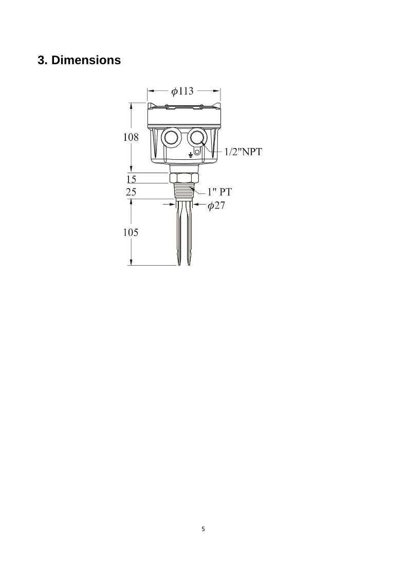
3. Dimensions ....................................................................................................... 5
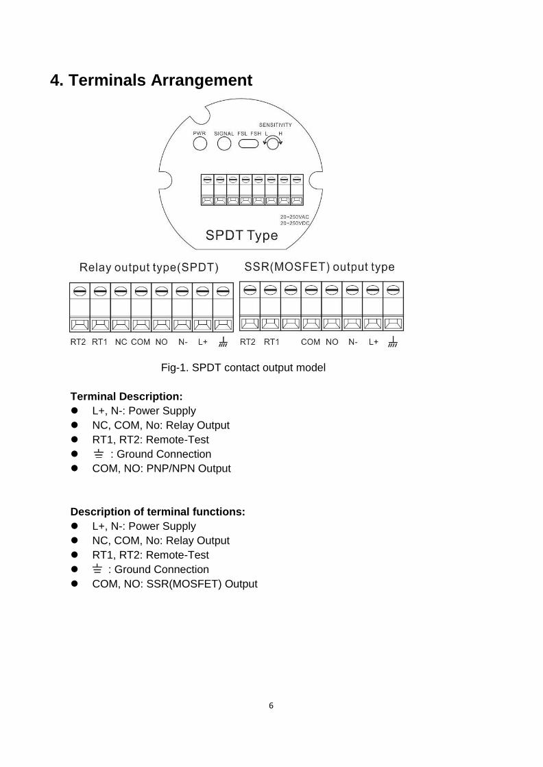
4. Terminals Arrangement ................................................................................... 6
5. Output Description ........................................................................................... 7
6. Panel Function .................................................................................................. 8
7. Output Mode ..................................................................................................... 9
8. Installation For Tuning Fork .......................................................................... 10

4
1. Introduction The tuning fork level switch is a mechanical resonant device which excited by piezoelectric (PZT) elements. When the measured medium comes into contact with the tuning fork, it will change the feedback resonant frequency due to the damping resonances between the exciting PZT and receiving PZT. By detecting the frequency and appropriately tuning the sensitivity of tuning fork level switch on measured material, such device can easily operate for monitoring the alarm level of measured material.
2. Feature 1. Providing a universal power supply for operating in voltage range of
20 to 250 (Vac / Vdc).
2. No calibration or complex setting procedure are needed, robust, free of
maintenance.
3. High / Low fail safe modes provide user the safety monitoring and real time
communication.
4. Equipped with Remote Self-Testing function (RST) to diagnostic the hardware
connection with peripherals
5
3. Dimensions
6
4. Terminals Arrangement
Fig-1. SPDT contact output model
Terminal Description:
L+, N-: Power Supply
NC, COM, No: Relay Output
RT1, RT2: Remote-Test
: Ground Connection
COM, NO: PNP/NPN Output
Description of terminal functions:
L+, N-: Power Supply
NC, COM, No: Relay Output
RT1, RT2: Remote-Test
: Ground Connection
COM, NO: SSR(MOSFET) Output

7
5. Output Description 1. Make sure provide power supply (L+/N-) in range of 20 to 250
(Vac or Vdc,50/60Hz)
and output relay (Relay or PNP/NPN before wiring. Detail please see Fig-1.
2. RT1 and RT2 are the testing points that easy user to verify the situation.
When the RT1 and RT2 are in electric short, it means the measured material
is in contact with the tuning fork level switch.
The Relay or PNP/NPN should be activated. In examining the tuning fork level
switch, user will finds it keep excitation.
3. Set OUTPUT MODE to FSH,Please refer to Fig 2 and 3:
Relay contact output:
a. When vibrating fork is not contacted with media or the bin is empty,Signal
is switched on. Relay N.O and COM are connected.
b. When vibrating fork is contacted with media, Signal is not switched on.
Relay N.C and COM are connected.
PNP/NPN contact output:
a. When vibrating fork is not contacted with media or the bin is empty, Signal
is switched on. Ourput transistor is connected and output functions.
b. When vibrating fork is contacted with media, Signal is not switched on.
MOSFET transistor is not connected and output doesn’t function.
4. Adjust OUTPUT MODE to FSL. (Please refer to Fig. 2, 3)
Relay contact output:
a. When vibrating fork is not contacted with media or the bin is empty, Signal
is not switched on. Relay N.C and COM are connected.
b. When vibrating fork is contacted with media, Signal is switched on. Relay
N.O and COM are connected.
PNP/NPN contact output:
a. When vibrating fork is not contacted with media or the bin is empty, Signal
is not switched on. Output transistor is not connected and output doesn’t
function.
b. When vibrating fork is contacted with media, Signal is switched on. Output
transistor is connected and output functions.
8
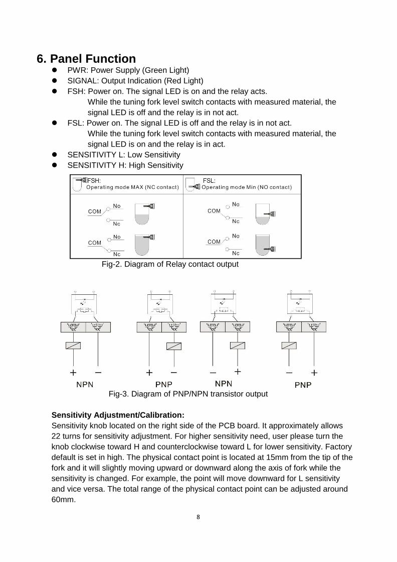
6. Panel Function PWR: Power Supply (Green Light)
SIGNAL: Output Indication (Red Light)
FSH: Power on. The signal LED is on and the relay acts.
While the tuning fork level switch contacts with measured material, the
signal LED is off and the relay is in not act.
FSL: Power on. The signal LED is off and the relay is in not act.
While the tuning fork level switch contacts with measured material, the
signal LED is on and the relay is in act.
SENSITIVITY L: Low Sensitivity
SENSITIVITY H: High Sensitivity
Fig-2. Diagram of Relay contact output
Fig-3. Diagram of PNP/NPN transistor output
Sensitivity Adjustment/Calibration:
Sensitivity knob located on the right side of the PCB board. It approximately allows
22 turns for sensitivity adjustment. For higher sensitivity need, user please turn the
knob clockwise toward H and counterclockwise toward L for lower sensitivity. Factory
default is set in high. The physical contact point is located at 15mm from the tip of the
fork and it will slightly moving upward or downward along the axis of fork while the
sensitivity is changed. For example, the point will move downward for L sensitivity
and vice versa. The total range of the physical contact point can be adjusted around
60mm.
9
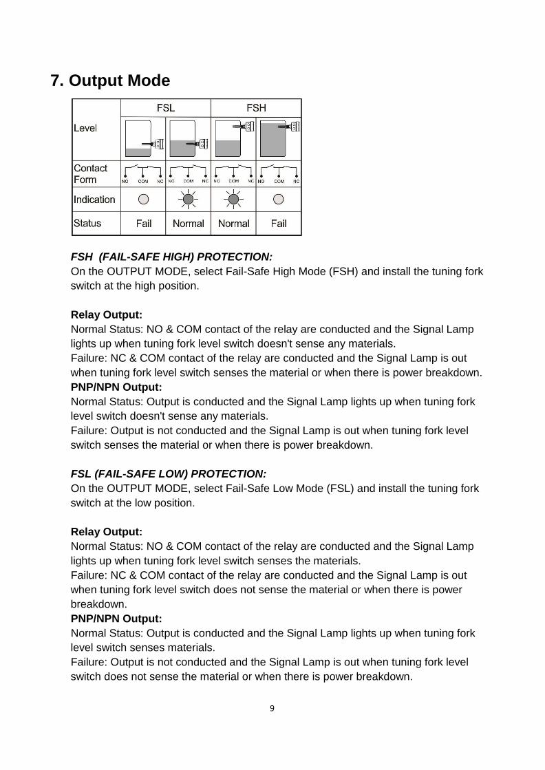
7. Output Mode
FSH (FAIL-SAFE HIGH) PROTECTION:
On the OUTPUT MODE, select Fail-Safe High Mode (FSH) and install the tuning fork
switch at the high position.
Relay Output:
Normal Status: NO & COM contact of the relay are conducted and the Signal Lamp
lights up when tuning fork level switch doesn't sense any materials.
Failure: NC & COM contact of the relay are conducted and the Signal Lamp is out
when tuning fork level switch senses the material or when there is power breakdown.
PNP/NPN Output:
Normal Status: Output is conducted and the Signal Lamp lights up when tuning fork
level switch doesn't sense any materials.
Failure: Output is not conducted and the Signal Lamp is out when tuning fork level
switch senses the material or when there is power breakdown.
FSL (FAIL-SAFE LOW) PROTECTION:
On the OUTPUT MODE, select Fail-Safe Low Mode (FSL) and install the tuning fork
switch at the low position.
Relay Output:
Normal Status: NO & COM contact of the relay are conducted and the Signal Lamp
lights up when tuning fork level switch senses the materials.
Failure: NC & COM contact of the relay are conducted and the Signal Lamp is out
when tuning fork level switch does not sense the material or when there is power
breakdown.
PNP/NPN Output:
Normal Status: Output is conducted and the Signal Lamp lights up when tuning fork
level switch senses materials.
Failure: Output is not conducted and the Signal Lamp is out when tuning fork level
switch does not sense the material or when there is power breakdown.

10
8. Installation For Tuning Fork Horizontal Installation:
1. Can be applied in viscosity, powder, and liquid. Do not install near substance
inlet. ( Figure 1)
2. Conduit faces downward at installation. ( Figure 2)
3. To be installed with the surface of two fork blades facing each other
horizontally. ( Figure 3)
( Figure 1) ( Figure 2) ( Figure 3)
Vertical Installation:
1. With high sensitivity, switching point is distanced 15mm away from the tip of
fork. ( Figure 4)
2. Opening of the two fork blades is to be as the flow direction. ( Figure 5)
3. Do not install near substance inlet. ( Figure 6)
( Figure 4) ( Figure 5)
( Figure 6)
11

12
M5734/0119