high-precision, advanced tuning fork balance ln...
TRANSCRIPT

360002M01
High-Precision, Advanced Tuning Fork Balance
LN Series
Operation Manual
SHINKO DENSHI CO., LTD.
● To ensure safe and proper use of the balance, please read this manual carefully.
● After reading this manual, store it in a safe place near the balance, so you can review it as needed.
IMPORTANT

PREFACE
Thank you for purchasing an LN Series electronic balance.
This balance is equipped with a high precision mechanism. It provides parts counting, percentage weighing, and limit functions helpful in weighing a certain amount, and has various other functions. This advanced balance employs a user-friendly program, and the key arrangement is also easy to operate. In addition, the fluorescent display is eye-friendly, and its high-speed, stable performance improves your work efficiency.
Check for the following accessories before use.
(1) Main Unit (2) Pan Base (3) Pan
LN210001~310001 : beforehand installed at factory
(4) AC adapter (5) Operation manual (6) Wind shield panel(5pcs.)
※for 220g~620g Capacitymodel

1
Contents
1 Precautions Relating to Use........................... 2 2 Names of Component Parts ........................... 5 3 Installation of the Balance and Operation
Check 3.1 Installation .............................................. 8 3.2 Windshield setting .................................. 8 3.3 Operation Check .................................... 9
4 Function1
4.1 Setting and Check................................ 12 4.2 Description of Function1....................... 13 4.3 Additional Functions............................. 16 4.4 Interface ............................................... 17
5 Function2....................................................... 18 6 Weighing Mode
6.1 Measurement Modes............................ 19 6.2 Weighing Machine................................ 19 6.3 Parts Counting ..................................... 20 6.4 Percentage Weighing ........................... 22 6.5 Unit Converting .................................... 24 6.6 Gravimeter ........................................... 25 6.7 Statistics Function ................................ 29
7 Addition Function
7.1 Cumulate Function ............................... 34 7.2 Net Addition Function ........................... 35
8 Limit Function
8.1 Setting the Limit Function..................... 36 8.2 Judgment and Saving........................... 36 8.3 Display of Judgment Results................ 36 8.4 Judge by Absolute Values .................... 37 8.5 Judge by Deviation Values ................... 39 8.6 Bar Graph for the 2-point Scale............ 42
9 Calibration and Span Test for the Balance
9.1 Span Adjustment...................................43 9.2 Span Test ..............................................44 9.3 Calibration of Built-in Weight.................45
10 Date and Time Setup .....................................46 11 Various Functions
11.1 Auto Sleep Function..............................47 11.2 Auto Power Off Function.......................47 11.3 Set Unit Function ..................................47 11.4 Minimum Readability Setting Function..47 11.5 Advice CAL ...........................................48 11.6 Date Display .........................................48 11.7 Time Stamp Output ...............................48 11.8 Save Tare Weight Function ...................48 11.9 Direct Start Function .............................48 11.10 Interval Output Function........................49 11.11 ID Number Entry. ..................................50 11.12 Entry of Weight Error ............................51
12 Input/Output Functions
12.1 RS232C Output ....................................52 12.2 Output to Peripherals ............................55 12.3 Type of Communication Texts ...............56 12.4 Output Data ..........................................56 12.5 Input Commands ..................................59 12.6 Special Format Output ..........................65
13 Use Printers....................................................67 14 Output in Compliance with
ISO/GLP/GMP.................................................68 15 Operate on Batteries .....................................71 16 Troubleshooting.............................................72 17 Specifications ................................................73 18 Conversion Table of Units.............................77

2
1 Precautions Relating to Use This Section "Precautions Relating to Use" sets forth precautionary notes that the user should
observe in order to prevent physical injury to the user and/or damage to property.
The nature of problems that may result in the event of improper operation, and consequential effects on the quality and performance of the balance, are indicated under the two categories of "Caution" and "Recommended," and explained using symbols.
This is a category to indicate improper handling that may cause physical injury or severe damage to property. Be sure to follow the directions for safe use to avoid serious consequences.
This term indicates steps that the user should take to ensure the quality and reliability of the balance.
Meanings of Symbols Each symbol is accompanied by an instruction.
Do not disassemble or modify the unit.
• Could cause malfunction or heat generation
Only AC power should be used. Only use the dedicated AC adapter.
• Use of other types of power or adapters may result in heat generation or malfunction of the balance.
Do not move the balance when a sample is loaded.
• The loaded sample may fall off the pan and cause an injury.
Recommended
Mandatory Symbol
: Indicates a "mandatory" action that should be executed without fail.
Check Level
Example
: Indicates a "prohibited" action that must not be executed.
Example
! Caution
Do Not Disassemble
Prohibitive Symbol Do Not Use
Do Not Move
Do Not Deviate from Ratings
! Caution

3
Do not place the balance on an unstable base or use the balance in a location where it may be subjected to shock.
• The loaded sample may fall off the pan. • Accurate measurement may be rendered
impossible.
Do not lay the AC adapter cable on the surface of the passage.
• Somebody may trip on the cable, causing the balance to fall off, thereby causing injury and/or damage to the balance.
Do not use the balance with its adjusters lifted. • The balance will become unstable, preventing
accurate measurement.
◆Do not touch the AC adapter or balance with
wet hands. • Danger of electric shock.
◆Do not use the balance in a location were it may
be subjected to excess moisture. • Electric shock or short-circuiting could occur. • The balance may be corroded, with resultant
malfunction.
◆Do not use the balance in a location where it
may be subjected to excess dust. • Risk of explosion or fire. • Short-circuit or lack of continuity may occur, leading
to a malfunction of the balance.
Calibrate the balance after installation or relocation.
• Measurement values may contain errors, preventing accurate measurement from being conducted.
Do Not Use
Do Not Drop
Do Not Leave Afloat
Don’t touch with wet hand
Recommended
Calibrate Balance
Don’t make it wet
Avoid excess dust

4
Avoid applying excess force or impact to the balance.
• Place the sample to be measured on the balance carefully to prevent breakage or malfunction.
Do not use the balance in a location were it may be subjected to abrupt changes in ambient temperature or humidity.
• Accurate measurement may be rendered impossible.
• Use the balance in an ambient temperature range of 5°C to 35°C and with 80% or lower relative humidity.
Do not leave the balance overloaded (When it is overloaded, () is displayed).
• Take down the loaded sample immediately to prevent breakage or malfunction.
Do not use the balance in a location where it is subject to direct sunlight.
• The indications would be illegible. • An internal temperature increase in the balance
may lead to inaccurate measurement.
If the balance is to be unused for an extended period of time, unplug the adapter.
• This conserves power and prevents deterioration.
Do not use volatile solvents for cleaning. • The body may be distorted. • To clean the unit of stains, use a piece of dry cloth
or cloth soaked in a small quantity of neutral detergent.
Do not use the balance in a location where it may be subject to air from an air-conditioning unit.
• Extreme changes in the ambient temperature may result in inaccurate measurements.
Do not use the balance on a soft floor.
• When loaded with a sample, the balance may tip or move, preventing accurate measurements from being conducted.
Do not use the balance when it is tilted.
• When the balance is tilted, an error may be caused, preventing accurate measurement from being conducted. Place the balance on a level surface.
Do Not Use
アダプターを抜く
Unplug Adapter
Do Not Apply Force
Do Not Overload
Do Not Use
Do Not Use
Do Not Use
Do Not Use
水平確認Check Level

5
2 Names of Component Parts 2.1 Main Unit 220g~620g capacity models
1200g~15kg capacity models
21kg,31kg capacity model
Rear
Bottom
Cover for a hanging hole. Inside is installed hook for under weighing for 220g~620g and 21kg,31kgmodel.
For 1200g~ 15kg capacity model, optional under weighing hook isnecessary
* It is necessary to perform Span adjustment in the case of measuring witha lower plate using a lower plate. When NET is displayed, weighing range isreduced and we cannot weigh up to the full capacity. In this case, useexternal weight having 50% or more of the full capacity and less enough notto show " " for such adjustment or test.
D-SUB9P RS232C output connector (male)
DIN8P connector for peripheral device output
Antitheft hole (Use a wire, etc., through the hole for preventing to be moved.)
Jack for the AC adapter
Wind shield
Adjuster
Pan
Fixed legs
Display Pan
Level
Operation key
Adjuster

6
2.2 Displayed Signs and Operation Keys
2.2.1 Displayed signs
Display Description
kg g Kilogram, gram
→0← Zero-point
− Minus
Net Tare sign
B/G Gross weight
Indication of stable balance (If this light is off, the balance is unstable.)
∗ Indicates that the addition function is enabled for accepting an additional load.
Pcs Parts counting
GN Grain unit
% Percentage weighing
# Unit converting
Σ Displays a sum total.
Displayed when data is output in compliance with ISO/GLP/GMP.
Lights up when date/time is being set or displayed. Blinks during interval output.
Judgment result display when the limit function is used
mom Momme
M Indicates that the value is set in memory (If it is flashing, the value is being saved.)
CAL Lights or blinks upon span adjustment or when Advice CAL is in operation.
• Bar graph
(Refer to Hints on page 42).
Displays a set unit.
Battery indicator. As the battery gets weaker, the sign is changed into [ ] or [ ]. (Refer to Section 15: Operate on Batteries on page 71).

7
2.2.2 Operation keys and their functions
Operation key Function
On/Off key Turns the balance on or off.
Print key Starts output. Also used to cancel the operation to set date/time.
Set key [Short press] Starts the setting a count or a percent. [Continuous press] Starts the setting of a limit value when the limit function is enabled.
Function key
[Short press] Switches the measurement mode. [Short press] Used to enter numerical values. [Short press] Used to select a function to set. [Continuous press] Calls functions.
Zero/Tare key
[Short press] Used for zero-setting or sets the display to zero by tare range. [Short press] Used to enter numerical values. [Short press] Used to select a function.
Cal key Starts span adjustment or a span test.
Arrow keys The arrow keys function in the same way as the Function key or the Zero/Tare key when you set a function or enter numerical values for additional functions.
LED (green) Stand by
Lights up when the power is off (standby). * The LED does not light up when the balance is operated on batteries.
LED (orange) Sleep Lights up when the auto sleep function is enabled.
0/T

8
3 Installation of the Balance and Operation Check 3.1 Installation 1 Attach the pan base and pan
to the main unit.
Attach the pan base to the main unit. Be sure that the "FRONT" indication is on the display side when attaching the pan base. Align the bosses on the body with the holes on the pan base before fastening the screws. After attaching the pan base, put the pan on it.
2 Level the balance.
Turn the adjusters so that the air bubble of the level is within the red circle. <Caution> Be sure that none of the adjusters is lifted from the floor.
3 Connect the AC adapter.
Connect the AC adapter to the balance. <Caution> (Refer to Section 15, "Operate on Batteries," on page 71 if the battery option is employed.)
3.2 Windshield setting(for 220g~620g capacity models) 1. Set a small panel in a large panel.
An edge with step should face the same side.
2. Set the other panel in the assembly above. 3. Place the windshield along the guide.
Position of the air bubble in the level
Jack for the AC adapter
step
step

9
3.3 Operation Check 3.3.1 Turn the power on and off and check the display
Connect the AC adapter. The balance enters standby mode, and the Stand by lamp (LED) lights up. Press the On/Off key. When the display is turned on, check it for any missing signs.
Check changes of the display.
Give the pan a slight press, and check that the display is changed. Check that the display goes back to zero when you lift your hand.
Stand by
Press the On/Off key again. The balance enters standby mode, and the Stand by lamp (LED) lights up.
3.2.2 Set a Tare Weight
1 Put tare (container) on the balance.
Put tare on the balance, and the weight is displayed.
2 Reset the display to 0.
Press the Zero/Tare key. The tare weight is set, and the display is reset to zero.
3 Put a sample on the balance.
The net weight of the sample in the container is displayed.
g
→0← g
g
→0← Net g
Net g
On/Off
Zero/Tare
0/T

10
Weigh additional samples
4 Reset the display to 0.
Press the Zero/Tare key. The gross weight of the sample on the pan is reset to 0.
5 Put an additional sample on the balance.
The weight of the additional sample is displayed. In this way, you can add a sample and weigh it by pressing the Zero/Tare key to reset the displayed weight to 0.
3.2.3 Display a gross weight
This is the function to display gross weight of samples with tare. Sample weight with tare is referred to as gross weight, and sample weight excluding tare is referred to as net weight. Gross weight can only be displayed when the balance is used as a weighing machine.
Put tare on the balance to set the tare weight.
Put a sample to weigh on the balance. At this point, the net weight of the sample is displayed.
Press the Function key once. The gross weight including the tare weight is displayed. The B/G sign is displayed.
When you press the Function key again, the balance is reset to the normal mode.
Caution: 1. Gross weight can only be displayed when the balance functions as a weighing machine.
2. While gross weight is displayed, you cannot set the tare. You can only adjust the zero-point.
→0← Net g
Net g
→0← Net g
Net g
B/G g
Net g
Zero/Tare
0/T
Function
Function

11
Hints
The following description applies commonly to the weighing machine, parts counting, percentage weighing, unit converting, and gravimeter functions. 1. A small amount of current is still flowing after the balance is turned off.
In a standby state, the Stand by lamp (LED) is lit. When the balance is turned on, the LED goes out. * The LED does not light up when the balance is operated on batteries.
2. The bar graph indicates the current load condition in relation to the weighing capacity. As the load approaches the weighing capacity, the bar gets closer to the right end. * When a tare range is set, the weight is still reflected in the bar graph even if the display indicates 0.
3. When the balance is stable, a circle is displayed. When it gets unstable, the sign goes out. When the balance is affected by wind or vibration, numeric values on the display may flicker or the "stable" sign may go out. In such a case, reset Function1 (refer to page 13) to improve the stability by referring to the following table.
Items of Function1 Influence of
wind or vibration
Stability Judgment
Response Speed
Setting the lowest digit of display for Unit A (B) [, ]
[, ] Small
Large
If the influence of the wind or vibration is small, set these setting items of Function1 higher. Set these items lower as the influence is increased.
4. When you reset the display to 0 or set a tare range, the display indicates 0, and the [→0←] sign is displayed. When you set a tare range, the [Net] sign is displayed.
5. When a tare range is set, the weighing capacity is reduced accordingly. Weighting capacity = original weighing capacity – tare weight
6. When [] is displayed after an object is put on the balance, it indicates that the weighing capacity is exceeded.
7. When you remove the pan, and the zero-point falls bellow the original zero-point, [] is displayed.
8. With any of the parts counting function, percentage weighing function, or unit converting function, the display still indicates zero when you press the pan unless any weight data of a sample is stored in the memory.
9. When you turn on the balance, it starts in the mode when it was turned off. For example, if you turn off the balance in the parts counting mode, it starts in the parts counting mode when it is turned on the next time.
g
Unstable
○ g
Stable
* When the zero-point deviates from the true zero-pointby one fourth of a division, the →0← sign goes out
→0← g
* When you set a tare range, the display indicates 0, and the Net sign is displayed.
→0← Net g

12
4 Function1 4.1 Setting and Check 1. Call Function1.
Keep pressing the Function key. When the display is changed to [] , release the key.
Now you can set Function1. The first setting item is displayed [ ]. (Refer to Section 4.2: Description of Function1 on page 13.)
2. Select the next setting item.
Every time you press the Function key, you are moved one item forward.
3. Change settings.
Every time you press the Zero/Tare key, the value in the right end is changed. Make appropriate settings.
4. Complete the setting of functions.
Press the Set key, or press the Function key several times until the balance enters the measurement mode. The setting of functions is completed, and the balance goes back into the measurement mode.
* The setting values of Function1 are held after the power is turned off.
Function setting using the arrow keys
Using the arrow keys located on the right side of the display can make function setting operations easier.
You can use the arrow keys instead of the Zero/Tare key or the Function key when any Function1 item is displayed. The arrow keys can be used as shown in the following figure:
Key released
Increase number
Return to the previous item Proceed to the next item
Decrease number
Function
Function
Continuous press
Set
Zero/Tare
0/T

13
4.2 Description of Function1 Item Set Value Description
Weighing machine (only supports weight measuring)
Parts counting (parts counting and weight measuring)
Percentage weighing (weight percent measuring and weight measuring)
Unit converting (coefficient multiplying and weight measuring)
Gravimeter (measurement of specific gravity)
Weighing Mode
Statistics function (statistical calculation and weight measuring)
Water Media
Any liquid other than water
Only a specific gravity value Output data Specific gravity, weight, and water temperature or the specific
gravity of the media (liquid) Disabled (Print key is used for output) D
ispl
ayed
for t
he
grav
imet
er.
Auto output Output once after a specific gravity measurement.
Disable additional functions.
Addition function ⇒ [ ] Limit function
Additional Functions
Addition and limit functions Refer to Section 4.3, Additional Functions
Disable Auto-Zero (Zero Tracking)
Enable
Functions to automatically adjust for a slight zero-point deviation.
Stability Judgment
Wide (Mild) ↓ Narrow (Strict)
Measurement by consecutive weighings
Response Speed
Fast ↓ Slow
Stop input/output
Numeric 6-digit format
Numeric 7-digit format
Extended 7-digit numeric format Interface
Special format
Refer to Section 4.4: Interface.
Special format1 Special formats
Special format2 Displayed when the setting is [ ].
Disable the Cal key.
1 Span adjustment with built-in weight (Auto-span adjustment)
Span test with built-in weight
Displayed only on the LN**R series balance.
2 Span adjustment with external weight
Span Adjustment Span Test
Span test with external weight
A star ( ) denotes a factory setting. 1 denotes a factory setting for the LN**R series, and 2 denotes a factory setting for the LN series.
14
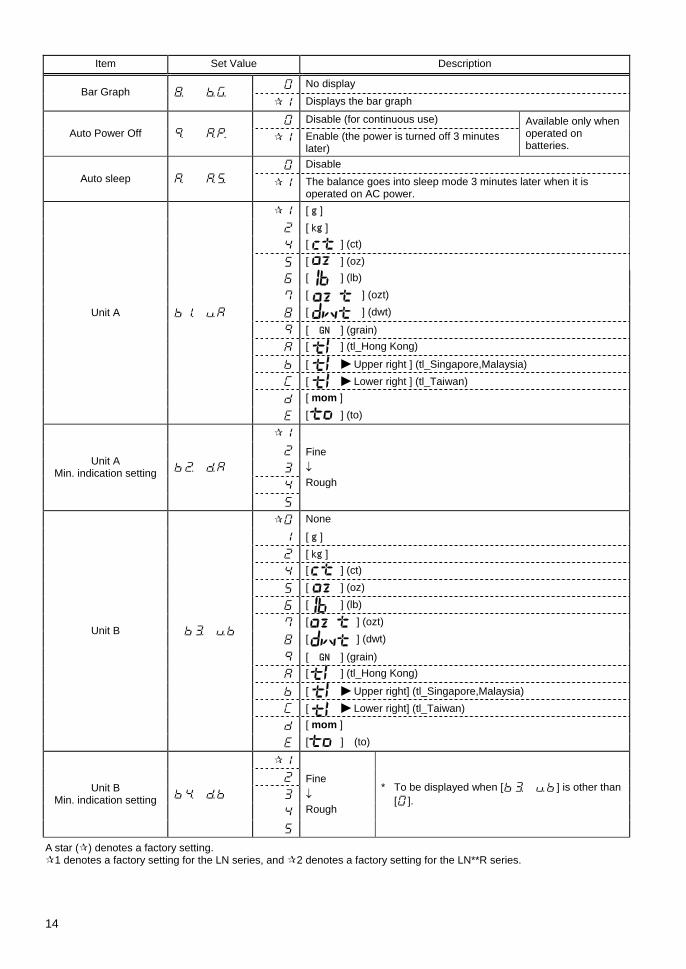
Item Set Value Description
No display Bar Graph
Displays the bar graph
Disable (for continuous use) Auto Power Off Enable (the power is turned off 3 minutes
later)
Available only when operated on batteries.
Disable Auto sleep The balance goes into sleep mode 3 minutes later when it is
operated on AC power. [ g ] [ kg ] [ ] (ct)
[ ] (oz) [ ] (lb)
[ ] (ozt)
[ ] (dwt)
[ GN ] (grain) [ ] (tl_Hong Kong)
[ Upper right ] (tl_Singapore,Malaysia) [ Lower right ] (tl_Taiwan) [ mom ]
Unit A
[ ] (to)
Unit A Min. indication setting
Fine ↓ Rough
None
[ g ] [ kg ] [ ] (ct)
[ ] (oz)
[ ] (lb)
[ ] (ozt)
[ ] (dwt)
[ GN ] (grain) [ ] (tl_Hong Kong)
[ Upper right] (tl_Singapore,Malaysia) [ Lower right] (tl_Taiwan) [ mom ]
Unit B
[ ] (to)
Unit B Min. indication setting
Fine ↓ Rough
* To be displayed when [ ] is other than [].
A star ( ) denotes a factory setting. 1 denotes a factory setting for the LN series, and 2 denotes a factory setting for the LN**R series.

15
Item Set Value Description
1 Disable Advice CAL
2 Enable Disable Compliance with
ISO/GLP/GMP Enable Disable Output of
CAL and span test
results
Enable
Disable Data compliant with GLP
Enable
English Dis
play
ed w
hen
[
] is
[].
Printed Language
Japanese (Katakana)
Output in Year-Month-Day format.
Output in Month-Day-Year format. Date Display
Output in Day-Month-Year format.
Disable Time Stamp Output
Outputs time together with measurement data.
Reset the display to 0 immediately after the Zero/Tare key is pressed.
Set Tare Range Reset the display to 0 when the balance is stabilized after the
Zero/Tare key is pressed. Disable
Store Tare Enable
The balance goes into the standby mode when the AC adapter is plugged in. Direct Start
The balance is turned on when the AC adapter is plugged in.

16
4.3 Additional Functions Displayed when [ ] is other than [].
Item Set Value Description
Always judge (even when the balance is unstable). Condition
Judge only when the balance is stable.
Above +5 ticks is covered in the judgment. (The range +5 ticks or less is not covered for judgment including negative values.) Range to Cover
Full range judgment (including negative values)
1-point scale (OK/LO)
2-point scale (HI/OK/LO)
3-point scale (scale of 1 to 4) Point Scale
4-point scale (scale of 1 to 5)
Judge by absolute values. Judge by
Judge by deviation values.
Buzzer is turned off for rank 1 (LO). Buzzer for rank 1
Buzzer turns on for rank 1 (LO).
Buzzer is turned off for rank 2 (OK). Buzzer for rank 2
Buzzer turns on for rank 2 (OK).
Buzzer is turned off for rank 3 (HI). Buzzer for rank 3
Buzzer turns on for rank 3 (HI).
Buzzer is turned off for rank 4. Buzzer for rank 4
Buzzer turns on for rank 4.
Buzzer is turned off for rank 5. Buzzer for rank 5
Buzzer turns on for rank 5.
Displays HI, OK, LO, or the rank. How to Indicate Results Bar graph for the 2-point scale (Available only when you select the
2-point scale) Output all the time (independently of external signal input).
Relay output control *1 Controlled by an external input signal.
Cumulate function Addition operation *2
Net addition function
*1 Set [ ] when the limit contact output option or the full pack option is used. Otherwise, use [ ].
*2 Displayed when [ ] is [] or [].

17
4.4 Interface Displayed when [ ] is [~].
Item Set Value Description
Stop output
Output continuously at all times
Output continuously if stable (Stop output if unstable)
Output once when the Print key is pressed (regardless of whether the balance is stable or unstable).
Output once when the balance is stable. After any sample is lifted causing the display to show zero or less value, outputs the next time any sample is put on again and the balance is stabilized.
Output once when the balance is stable. Stop output when unstable. Outputs once when the balance is stabilized again (including the zero point) even if it is not reloaded.
Output once when the balance is stable. Output continuously when unstable. Output is stopped after a single output when the balance is stable even if it is not reloaded.
Output once when the Print key is pressed if the balance is stable.
Output once immediately after a specified interval.
Output Control
Output once immediately after a specified interval if the balance is stable.
1200 bps
2400 bps
4800 bps
9600 bps Baud Rate
19200 bps
None
Odd Parity
Even Displayed when [ ] is set to [to].
7 bits Data Length
8 bits
1 bit Stop Bits
2 bits
Displayed when [ ] is set to [,].
Embed 0 (30H). Unused Higher Digits
Filled by space characters (20H).
The A00 and Exx responses are used. Response Commands
The ACK and NAK responses are used.
A star ( ) denotes a factory setting. * The data output interval is 0.1 to 1 second for continuous output. (The interval varies with the measurement conditions, etc.)

18
5 Function2 5.1 Setting and Check 1 Call Function2.
Press the Function key while holding down the Zero/Tare key.
Press the Function key while holding down the Zero/Tare key. When [] is displayed, release the key.
The display will be changed to show [ ].
2 Change settings.
Use the Function key to select a setting item. Change the setting in the right end with the Zero/Tare key.
3 Complete the setting of functions.
Press the Set key, or press the Function key several times until the balance enters measurement mode. The setting of Function2 is completed, and the balance goes back into the measurement mode.
5.2 Description of Function2 Item Set Value Description
Disable * Setup of ID No. Enable
Disable * Setting instrumental error of
the weight in use
Enable
Disable * Calibration of Built-in Weight
Enable Only supported by the LN**R series
Do not use.
Use of weight error Weight error values set are used upon span / span adjustment to use external weights or when a built-in weight is to be calibrated.
A star ( ) denotes a factory setting.
Caution: The setting values for the items marked by an asterisk (*) are reset to factory defaults every time you call it.
Key released
19
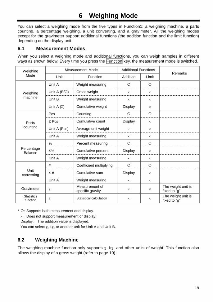
6 Weighing Mode You can select a weighing mode from the five types in Function1: a weighing machine, a parts counting, a percentage weighing, a unit converting, and a gravimeter. All the weighing modes except for the gravimeter support additional functions (the addition function and the limit function) depending on the display unit.
6.1 Measurement Modes
When you select a weighing mode and additional functions, you can weigh samples in different ways as shown below. Every time you press the Function key, the measurement mode is switched.
Measurement Mode Additional Functions Weighing Mode Unit Function Addition Limit
Remarks
Unit A Weight measuring
Unit A (B/G) Gross weight × ×
Unit B Weight measuring × × Weighing machine
Unit A (Σ) Cumulative weight Display ×
Pcs Counting
Σ Pcs Cumulative count Display ×
Unit A (Pcs) Average unit weight × × Parts
counting
Unit A Weight measuring × ×
% Percent measuring
Σ% Cumulative percent Display × Percentage Balance
Unit A Weight measuring × ×
# Coefficient multiplying
Σ # Cumulative sum Display × Unit converting
Unit A Weight measuring × ×
Gravimeter g Measurement of specific gravity × × The weight unit is
fixed to "g". Statistics function g Statistical calculation × × The weight unit is
fixed to "g".
* : Supports both measurement and display. ×: Does not support measurement or display. Display: The addition value is displayed. You can select g, kg, or another unit for Unit A and Unit B.
6.2 Weighing Machine
The weighing machine function only supports g, kg, and other units of weight. This function also allows the display of a gross weight (refer to page 10).

20
6.3 Parts Counting The parts counting function employs an automatic memory update method, also referred to as a Self Counting System. When you put a specified number of samples on the balance, and put additional samples, the balance automatically updates the average unit weight of the samples. However, you cannot add more than two times as many samples as the first reading. This mechanism allows accurate counting.
6.3.1 Sampling
1 Select the parts counting function.
Select the parts counting function [ ] in Function1. Then, press the Set key to return to the measurement mode. The weighing mode is changed to "parts counting". Place a tare container on the balance as appropriate.
2 Start sampling.
Press the Function key for a few seconds. When the display indicates [ ], release the key. The display then blinks [ Pcs]. This indicates to put 10 samples on the balance.
3 Change the number of samples as required.
If weight variation is significant between samples or unit weight is light, press the Zero/Tare key to sufficiently increase the number of samples. Each time you press the key, the value in the right end is changed. Select an appropriate value. If you do not need to change the number, skip this step.
4 Put a sample on the balance.
Put the displayed number of samples on the balance, and press the Function key. The display then blinks [ Pcs].
How the value changes
Pcs
Pcs
M
Pcs
Key released
Function
Zero/Tare
0/T
Function
Continuous press
21
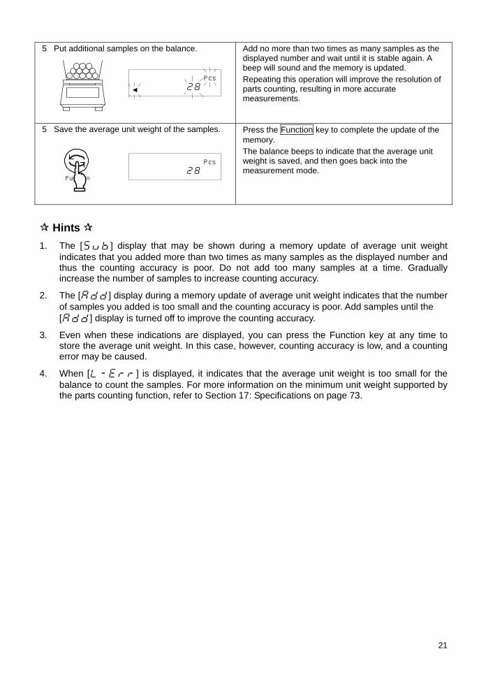
5 Put additional samples on the balance.
Add no more than two times as many samples as the displayed number and wait until it is stable again. A beep will sound and the memory is updated. Repeating this operation will improve the resolution of parts counting, resulting in more accurate measurements.
5 Save the average unit weight of the samples.
Press the Function key to complete the update of the memory. The balance beeps to indicate that the average unit weight is saved, and then goes back into the measurement mode.
Hints 1. The [] display that may be shown during a memory update of average unit weight
indicates that you added more than two times as many samples as the displayed number and thus the counting accuracy is poor. Do not add too many samples at a time. Gradually increase the number of samples to increase counting accuracy.
2. The [] display during a memory update of average unit weight indicates that the number of samples you added is too small and the counting accuracy is poor. Add samples until the [] display is turned off to improve the counting accuracy.
3. Even when these indications are displayed, you can press the Function key at any time to store the average unit weight. In this case, however, counting accuracy is low, and a counting error may be caused.
4. When [] is displayed, it indicates that the average unit weight is too small for the balance to count the samples. For more information on the minimum unit weight supported by the parts counting function, refer to Section 17: Specifications on page 73.
Pcs
Pcs
Function

22
6.4 Percentage Weighing 6.4.1 Set a reference weight by weighing an actual sample
You can make the display indicate the weight percentage (%) of a sample with respect to a reference sample weight.
1 Select the percentage weighing function.
Select the percentage weighing function [ ] in Function1. Then, press the Set key to return to the measurement mode. The weighing mode is changed to "percentage weighing". Place a tare container on the balance as appropriate.
2 Set a reference weight.
Press the Function key for a few seconds. When the display indicates [ ], release the key.
3 Put a sample on the balance.
The weight display begins to blink. If you have already set a reference weight, that value is displayed. Put a reference sample on the balance.
4 Save the reference weight.
Press the Function key. The balance beeps to indicate that the value was saved, and then goes back into the measurement mode.
5 Put a sample to weigh on the balance.
The display indicates the weight percentage (%) of the sample with respect to the reference sample.
Caution: The least significant digit of the percent value is automatically selected in accordance with the reference weight saved.
Min. display digit Range of Reference Weight
Reference weight < Lower weight limit
1% Lower weight limit ≤ Reference weight < Lower weight limit × 10
0.1% Lower weight limit × 10 ≤ Reference weight < Lower weight limit × 100
0.01% Lower weight limit × 100 ≤ Reference weight
You cannot set a value below the lower weight limit as a reference weight.
* The lower weight limit depends on the model. For more information, refer to Section 17: Specifications on page 73.
%
%
M g
Key released
Function
Function
Continuous press

23
6.4.2 Set a reference weight by entering a value
You can enter a reference weight in the balance, and then make the display indicate the weight percentage (%) of a sample with respect to the reference.
1 Set a reference weight.
Press the Function key for a few seconds. When the display indicates [ ], release the key. The weight display begins to blink. If you have already set a reference weight, that value is displayed.
2 Enter a reference weight.
Press the Zero/Tare key. A () blinks in the right end of the display.
3 Select a number.
Every time you press the Zero/Tare key, the number changes.
4 Digit selections to enter a reference weight.
Press the Function key so the number entered is shifted to the left, and you can enter the next digit.
5 Save the reference weight.
Press the Set key. The display indicates the weight percentage (%) of the sample with respect to the reference weight.
6 Put a sample to weigh on the balance.
Put a sample to weigh on the balance. The display indicates the weight percentage (%) of the sample with respect to the reference.
Use the arrow keys to enter values
You can use the arrow keys to enter values instead of the Zero/Tare key or the Function key.
The arrow keys can be used as shown in the following figure:
M g
M g
%
Increase number
Move to left input digit Move to right input digit
Decrease number
⇒⇒⇒~⇒⇒⇒小数点
マイナスMinus
Decimal point ●
Key released Function
Continuous press
Set
Zero/Tare
0/T

24
6.5 Unit Converting The unit converting function multiplies the weight of a sample on the balance by a saved coefficient, and displays the result.
1 Select the unit converting function.
Select the unit converting function in Function1 [ ]. Then, press the Set key to return to the measurement mode. The weighing mode is changed to "unit converting." Place a tare container on the balance as appropriate.
2 Set a coefficient.
Press the Function key for a few seconds. When the display indicates [ ], release the key. The display blinks a coefficient. If you already have set any coefficient, that value is displayed.
3 Enter a weight.
Press the Zero/Tare key. A [] blinks in the right end of the display.
4 Select a number.
Every time you press the Zero/Tare key, the number changes.
5 Select digit places to specify a coefficient.
Press the Function key so the number entered shifts to the left and you can enter the next digit.
6 Save the coefficient.
Press the Set key. The balance beeps to indicate that the value was saved, and then goes back into the measurement mode.
7 Put a sample to weigh on the balance. Example) 4700 (displayed) = 2.35 (coefficient) × 2000 g (sample)
Put a sample to weigh on the balance. The weight of the sample is multiplied by the coefficient, and the result is displayed.
You can use the arrow keys to enter values instead of the Zero/Tare key or the Function key (Refer to page 23).
Key released
#
M
#
M
#
⇒⇒⇒~⇒⇒⇒小数点
マイナスMinus
Decimal point●
#
Function
Continuous press
Zero/Tare
0/T
Set

25
6.6 Gravimeter When the balance is used as a gravimeter, specific gravity is measured by hanging a sample, thus requiring an optional hooking device. Any net or cage, hanging strings, or containers that may be required to hang the sample on the balance should be prepared by the user for the particular sample to be subjected to the measurement.
The measurement method complies with the requirements specified in JIS Z 8807, "Measuring Methods for Specific Gravity of Solid."
6.6.1 Measurement procedures for specific gravity
1 Preparation for specific gravity measurements
Put the balance on a pedestal and attach the hanging hook. Hang a cage or the like that is used for holding the sample. As the sample weight is also measured in water, prepare a container with water whose size is enough to put the entire cage into the water.
2 Set the balance for gravimeter and select the media.
Select the gravimeter function [ ] in Function1. Select [ : water] or [:Other than water] for the media [ ].
3 Display weight
Press the Set key to show the weight. With gravimeter measurements, [] will be indicated above the [g] symbol.
4. Measure the water temperature in the container and enter the value into the balance.
Press and hold the Zero/Tare key to enter the temperature setting mode and then enter the water temperature (for any media other than water, enter the specific gravity value of the media). (Refer to the descriptions on page 27 for the procedures to enter the value.) The value entered is held even after the power is turned off.
5 Reset the display to 0.
Press the Zero/Tare key while only the cage is hung to reset the display to zero.
Hanging measurement Container with water (media)
g
g
Set
Zero/Tare
0/T
Zero/Tare
0/T
Continuous press

26
6. Measure the weight of the sample in the air.
Measure the weight of the sample put in a cage or on a pan, in the air. After the weight display is stable, press the Set key to enter the weight. When the weight is entered, a [] is displayed in the bottom left of the display and a [▲] is shown in the top left part of the display.
7. Submerge only the hanging cage and set to zero.
Before the measurement in water, submerge only the cage and set the indication to zero. This is for removing any residual error due to the hanging cage. * Pressing the Print key after entering the sample
weight in the air will clear the weight value entered.
8. Measure the weight of the sample in water.
Put the sample on the hanging cage and submerge the entire volume. Be careful that the cage does not touch the bottom of the container. After the weight display is stable, press the Set key to enter the weight.
9. The specific gravity value will be displayed.
When the weight is entered, the resulting specific gravity value will be displayed. The [] symbol will be lit in the top right of the display while a specific gravity value is displayed. Specific gravity is has no unit.
10. Return to weight display by the Set key.
When you press the Set key while a specific gravity value is displayed, the display returns to the weight display of the gravimeter function.
Hints Measurements with smaller size samples may result in some variations in the measured specific gravity values. In particular, any sample whose specific gravity is larger tends to show more variation.
Use as large a sample as possible for obtaining more stable measurements.
g
▲
g
▲
g
g
Zero/Tare
0/T
Set
Set
Set

27
6.6.2 Entering water temperature or the specific gravity of the media
This is for entering correction data for the liquid media to be used for the measurement. Enter water temperature if the media is water. Otherwise, enter the specific gravity value of the liquid. Use Function1 for selecting the media as follows:
Correction data input procedures
1 Set the balance for gravimeter and select the media.
Set Function1 to select gravimeter and select either [ : water] or [ : Other than water] for the media [ ].
2 Call the mode to enter a correction value.
Press and hold the Zero/Tare key to enter the temperature setting mode and then enter the water temperature (for any media other than water, enter the specific gravity value of the media). If the media is water, [] is displayed on the right side of the display. Otherwise, [ ] will be indicated instead.
3 Press the Zero/Tare key.
Press the Zero/Tare key. The [] indication blinks.
4. Enter the value.
Use the Zero/Tare and Function keys for this entry. The Zero/Tare key is used for incrementing the figure and the Function key is used for moving the digit to the right. (This operation can also be made by using the arrow keys. Refer to page 23).
5 Save the value.
Upon completing the entry, press the Set key to return to the weight display mode.
Caution The acceptable range of numeric entry is specified as follows:
Media Input Data Range Water Water temperature 0.0 to 99.9°C Any liquid other than water Density 0.0001 to 9.9999 g/cm3
If any value outside the above specified range is entered, either the minimum or the maximum value within the range will be set.
The value set is held even after the power is turned off.
⇒⇒⇒~⇒⇒⇒小数点
マイナスMinus
Decimal point●
」
Set
Zero/Tare
0/T
Zero/Tare
0/T
Continuous press

28
6.6.3 Gravimeter measurement data output
(1) Output before gravimeter measurement
With the gravimeter function, the operation is with the [ ] (output once when Print key is pressed after it is stabilized) mode, regardless of the setting by [].
(2) Output while specific gravity is displayed
[ ] is used for selecting the output contents.
The output method can also be selected by [ ].
(3) Output (print) format
When "specific gravity, weight, and actual water temperature or density of media" are all selected in [ ], …. If "specific gravity only" is selected, only the second line value will be output.
In addition, if any statistical calculation is made for the printer, the values in the second line will be printed being prefixed by a serial number.
Language selection between English and Japanese for printing is made by the GLP function [ ] of Function1.
1) When water is selected
English Japanese (Katakana)
2) When other than water is selected
English Japanese (Katakana)
1 2 3 4 5 6 7 8 9 10 11 12 13 14 15
1 D E N S I T Y S O L I D2 × × . × × ×3 S A M P L E W E I G H T4 × × × × × . × × × g5 T E M P E R A T U R E N O W6 × × × × × × × . × C7
1 2 3 4 5 6 7 8 9 10 11 12 13 14 15
1 コ タ イ ヒ シ " ュ ウ2 × × . × × ×3 シ " ュ ウ リ ョ ウ4 × × × × × × × × g5 シ " ツ ス イ オ ン6 × × × × × × × . × C7
1 2 3 4 5 6 7 8 9 10 11 12 13 14 15
1 D E N S I T Y S O L I D2 × × . × × ×3 S A M P L E W E I G H T4 × × × × × . × × × g5 T E M P E R A T U R E N O W6 × × × × × × × . × C7
1 2 3 4 5 6 7 8 9 10 11 12 13 14 15
1 コ タ イ ヒ シ " ュ ウ2 × × . × × ×3 シ " ュ ウ リ ョ ウ4 × × × × × × × × g5 ハ " イ タ イ ミ ツ ト "6 × × × × . × × × × d s7
1 2 3 4 5 6 7 8 9 10 11 12 13 14 15
1 D E N S I T Y S O L I D2 × × . × × ×3 S A M P L E W E I G H T4 × × × × × . × × × g5 D E N S I T Y M E D . L I Q6 × × × × . × × × ×7

29
6.7 Statistics Function This is a function to collect weight data and display statistics such as the maximum and average values. Regardless of which function is selected, the measurement unit is set to “g,” and the minimum value is displayed to the maximum number of decimal places available.
6.7.1 Calculation items The statistics displayed by the statistics function (calculation items) are as follows: To find out which calculation item is currently selected, see the display examples below. indicates that [] is lit, and indicates that [] is not lit.
Calculation item Display example
Maximum value
Minimum value
Average value
Standard deviation
Range (maximum value - minimum value)
Coefficient of variation
Number of data points
SUM
* The average value, standard deviation, and coefficient of variation are calculated using the following equations:
Average value ∑=
=N
iix
N 1
1; Standard deviation
)1(
)()(1
2
1
2
−⋅
−⋅=
∑ ∑= =
NN
xxNN
i
N
iii
; and
Coefficient of variation (%)100 valueAverage
deviation Standard×=
where ix is the ith measured value and N is the number of data points.
g
g
g
g
g
%
g
Σ
30
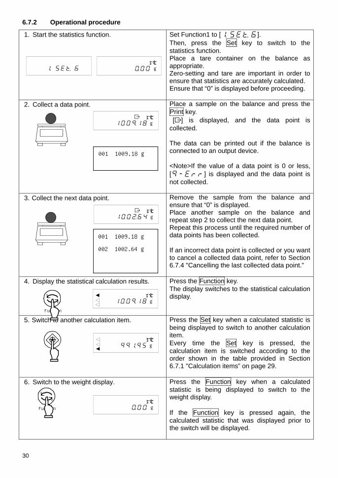
6.7.2 Operational procedure
1. Start the statistics function.
Set Function1 to [ ]. Then, press the Set key to switch to the statistics function. Place a tare container on the balance as appropriate. Zero-setting and tare are important in order to ensure that statistics are accurately calculated. Ensure that “0” is displayed before proceeding.
2. Collect a data point.
Place a sample on the balance and press the Print key. [] is displayed, and the data point is collected. The data can be printed out if the balance is connected to an output device. <Note>If the value of a data point is 0 or less, [] is displayed and the data point is not collected.
3. Collect the next data point. Remove the sample from the balance and ensure that “0” is displayed. Place another sample on the balance and repeat step 2 to collect the next data point. Repeat this process until the required number of data points has been collected. If an incorrect data point is collected or you want to cancel a collected data point, refer to Section 6.7.4 "Cancelling the last collected data point.”
4. Display the statistical calculation results.
Press the Function key. The display switches to the statistical calculation display.
5. Switch to another calculation item. Press the Set key when a calculated statistic is being displayed to switch to another calculation item. Every time the Set key is pressed, the calculation item is switched according to the order shown in the table provided in Section 6.7.1 "Calculation items” on page 29.
6. Switch to the weight display. Press the Function key when a calculated statistic is being displayed to switch to the weight display. If the Function key is pressed again, the calculated statistic that was displayed prior to the switch will be displayed.
Function
Function
Set
g
g
g
g
001 1009.18 g
g
001 1009.18 g
002 1002.64 g
g

31
Caution In step 2, press the Print key only when the output control is set to [ ]. If the
output control is set to [ ], the data is automatically output once when the balance is stable. If the statistics function is selected, only or can be enabled. If the output control is set to anything other than these three settings, [ ] is selected.
If the number of data points collected exceeds 999, or the number of digits of the “SUM” value exceeds the number of the digits displayed, the [] is displayed, and the statistical calculation is canceled. Delete the statistical calculation result.
When the statistical calculation result is displayed, the auto sleep function, external RS commands, and external tare are not activated.
Hints The following briefly describes the key operation of the statistics function. To display the next menu item, press the Set key or , and to display the previous menu item, press the .
Statistical calculation display
MAX
Weight display
MIN
Number of data points
Total
0/TCancel last collected data point (Refer to 6.7.4 on page 33.)
0/TClear statistical calculation result (Refer to 6.7.5 on page 33.)
Return to previous item.
Proceed to next item.
*1 The previously displayed calculation item is displayed.
*2 Pressing the Set key after the “SUM” is displayed returns to the “MAX.”
Switching
*1
*2
32
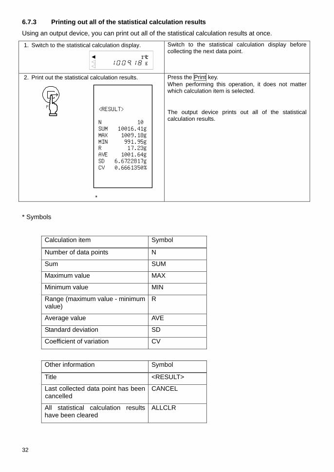
6.7.3 Printing out all of the statistical calculation results
Using an output device, you can print out all of the statistical calculation results at once.
1. Switch to the statistical calculation display.
Switch to the statistical calculation display before collecting the next data point.
2. Print out the statistical calculation results.
*
Press the Print key. When performing this operation, it does not matter which calculation item is selected.
The output device prints out all of the statistical calculation results.
* Symbols
Calculation item Symbol
Number of data points N
Sum SUM
Maximum value MAX
Minimum value MIN
Range (maximum value - minimum value)
R
Average value AVE
Standard deviation SD
Coefficient of variation CV
Other information Symbol
Title <RESULT>
Last collected data point has been cancelled
CANCEL
All statistical calculation results have been cleared
ALLCLR
Print <RESULT>
N 10SUM 10016.41gMAX 1009.18gMIN 991.95gR 17.23gAVE 1001.64gSD 6.6722817gCV 0.6661350%
g

33
6.7.4 Cancelling the last collected data point
You can cancel the last collected data point only once.
1. Switch to the statistical calculation display.
Switch to the statistical calculation display before collecting the next data point.
2. Switch to the “N” calculation item.
Press the Set key several times until “N” is displayed.
When the “N” calculation item has been selected, three “” symbols are displayed.
3. Cancel the last collected data point.
Press the Zero/Tare key to cancel the last collected data point.
* You cannot cancel the second to last data point. If you press the Zero/Tare key again after a data point has been deleted, [] is displayed.
6.7.5 Clearing all of the statistical calculation results
You can clear all of the collected data points. As doing so will result in all of the data points being deleted, print out the statistical calculation results, if necessary, before proceeding with this operation.
1. Switch to the statistical calculation display.
Switch to the statistical calculation display.
2. Switch to the "SUM" calculation item.
Press the Set key several times until "SUM" is displayed.
When the "SUM" calculation item has been selected, the "Σ" sign is displayed.
3. Clear the statistical calculation results.
Press the Zero/Tare key to clear the statistical calculation results.
*The statistical calculation result is cleared when the function [ ] is set to a value other than [], or the power is turned off.
Set
Zero/Tare
0/T
g
Set
Zero/Tare
0/T
g
g
Σ
g
Σ

34
7 Addition Function The addition function allows you to find the cumulative weight of samples put on the balance one after another. Except for the gravimeter function, all other functions, i.e., weighing machine, parts counting, percentage weighing, and unit converting functions support the addition function.
7.1 Cumulate Function With the cumulate function, a cumulative weight can be obtained while samples are reloaded.
1 Set Function1.
Set Function1 from [ ] to [ ]. Then, press the Set key to return to the measurement mode.
2 Reset the display to 0. Press the Zero/Tare key for zero adjustment or for tare range.
3 Put samples on the balance, and obtain the weight.
Put samples to weigh on the balance. When the asterisk (*) sign is displayed, you can put additional samples on. When [] is displayed, press the Set key. The displayed value is added, and the cumulative value is displayed with the [Σ] sign for several seconds.
4 Put another sample on the balance. Unload the balance, check that the display indicates 0, and put different samples on.
5 Read the weight.
When [] is displayed, press the Set key.
After it is stabilized, the displayed value is added, and the cumulative weight is displayed with the [Σ] sign for several seconds.
6 Display the cumulative weight.
Press the Function key twice.
The sign [Σ] will be lit and the cumulative value will be shown. (The number of times the Function key is pressed depends on the type of the balance.)
7 Clear the cumulative weight. Press the Zero/Tare key with the cumulative weight displayed (step 4) to reset the display to 0.
Obtain a cumulative weight without reloading the balance Press the Zero/Tare key in step 2 without unloading
the balance. This will reset the display to 0. Put additional samples on, and press the Set key. Then, the weight is cumulated.
Caution: 1. The addition function is available only when the display is once set to zero. 2. If [] is displayed when you press the Set key, it indicates that you put additional samples on
twice, that you unloaded some samples, or that you pressed the key without adding samples. 3. You can add samples when an asterisk (*) is displayed. 4. The [ ] display with Function1 can be used for turning ON/OFF the function to wait for
stabilization upon additions.
Net
g
* g
Σ g
Σ g
* g
Function
Set
Zero/Tare
0/T
Zero/Tare
0/T
Zero/Tare
0/T
Set
35
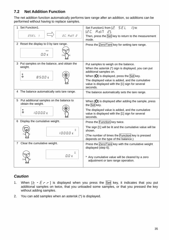
7.2 Net Addition Function
The net addition function automatically performs tare range after an addition, so additions can be performed without having to replace samples.
1 Set Function1.
Set Function1 from [ ] to [ ]. Then, press the Set key to return to the measurement mode.
2 Reset the display to 0 by tare range. Press the Zero/Tare key for setting tare range.
3 Put samples on the balance, and obtain the weight.
Put samples to weigh on the balance. When the asterisk (*) sign is displayed, you can put additional samples on. When [] is displayed, press the Set key. The displayed value is added, and the cumulative value is displayed with the [Σ] sign for several seconds.
4 The balance automatically sets tare range. The balance automatically sets the tare range.
5 Put additional samples on the balance to obtain the weight.
When [] is displayed after adding the sample, press the Set key. The displayed value is added, and the cumulative value is displayed with the [Σ] sign for several seconds.
6 Display the cumulative weight.
Press the Function key twice.
The sign [Σ] will be lit and the cumulative value will be shown. (The number of times the Function key is pressed depends on the type of the balance.)
7 Clear the cumulative weight. Press the Zero/Tare key with the cumulative weight displayed (step 6). * Any cumulative value will be cleared by a zero
adjustment or tare range operation.
Caution 1. When [] is displayed when you press the Set key, it indicates that you put
additional samples on twice, that you unloaded some samples, or that you pressed the key without adding samples.
2. You can add samples when an asterisk (*) is displayed.
* g
* g
Σ g
Σ g
Net
g
Function
Zero/Tare
0/T
Set
Set
Zero/Tare
0/T

36
8 Limit Function The limit function judges a weight based on limit values that you have stored on the balance.
The limit judgment result will be indicated by the position where the triangle [] is lit. When one or two points are set, the resulting display will be either HI (high), OK (proper), or LO (low). With a 3 or 4 point setting, 5 triangles [] are used to provide more detailed judgments.
8.1 Setting the Limit Function Make the settings of the limit function in Function1. While the limit function provides various setting items, carefully read Section 4.3: Additional Functions, on page 15, before actually performing the settings.
8.2 Judgment and Saving A limit value can be judged in the following two ways. Select an appropriate one in Function1.
(1) Judge by absolute values ・・・・・・ Specify an upper weight limit or a lower weight limit directly. (2) Judge by deviation values・・・・・・ Specify an upper limit or a lower limit with respect to a
reference weight.
A limit value can be stored in the following two ways. They can be used in combination with either of the above judgment methods.
(1) Put actual samples on the balance ・・ Put an actual sample on the balance, and save the weight as a limit value.
(2) Enter values・・・・・・・・・・・・・・・・・・・・・・ Enter a limit value using the keys.
* Once a limit value is entered, it is held after the balance is turned off. * You can set separate limit values for the weighing machine, parts counting, percentage
weighing, and unit converting functions. * When you enter a limit value, it is treated differently between the two judgment methods. (Refer
to Caution 9 on page 41.)
8.3 Display of Judgment Results When one or two points are set, a [] is displayed next to one of HI, OK, and LO in the left of the display depending on the judgment result.
Judgment Result
When one point (lower limit) is set
When two points (lower and upper limits) are set
HI (high) N/A Weight > Upper limit OK (proper) Lower limit ≤ Weight Lower limit ≤ Weight ≤ Upper limit LO (low) Lower limit > Weight Lower limit > Weight
When 3 or 4 points are set, triangles [] are displayed in 4 or 5 levels according to the judgment result.
Judgment Result 3 or 4 points Rank 5 Fourth point ≤ Weight Rank 4 Third point ≤ Weight < Fourth point Rank 3 Second point ≤ Weight < Third point Rank 2 First point ≤ Weight < Second point Rank 1 Weight < First point
ランク5 ランク4 ランク3 ランク2 ランク1
HI
OK
LO
Rank 5 Rank 4 Rank 3 Rank 2 Rank 1

37
8.4 Judge by Absolute Values 8.4.1 Set two limit values by putting actual samples on the balance
1 Start the limit function.
Press the Set key for a few seconds. When the display indicates [ ], release the key. The current lower limit is displayed next to [LO ].
2 Put the lower limit sample on the balance.
Put the lower limit sample on the pan.
3 Save the lower limit.
Press the Function key. When a lower limit is saved, the value is displayed for a while. * To set only one point, ignore the following steps.
4 Set an upper limit.
The display then indicates [ ], and you can now set an upper limit. The current upper limit is displayed next to [HI ].
5 Put the upper limit sample on the balance.
Put the upper limit sample on the pan.
6 Save the upper limit.
Press the Function key. When an upper limit is saved, that value is displayed for a while. Then the balance goes back into measurement mode.
* For the case of three or four point setting, repeat the above steps 2 through 3. Limit values saved are displayed as [ ] - [ ] or [ ] rather than [ ] or [ ]. In addition, a triangle [] on the left side of the display will be lit at the same time for indicating the setting level.
『 』(第4設定点)
『 』(第3設定点)
『 』(第2設定点)『 』(第1設定点)
HI
OK
LO
Fourth point
Third point
Second point First point
Function
Function
Set
Continuous press

38
8.4.2 Set two limit values by entering values
1 Start the limit function.
Press the Set key until the display indicates [ ]. The current lower limit is displayed next to [LO ].
2 Switch to the value input screen.
Press the Zero/Tare key. A () blinks in the right end of the display.
3 Enter a number.
Press the Zero/Tare key to change the blinking number. Every time you press the key, the number changes.
4 Select digit places.
Press the Function key, and the specified number shifts to the left, and you can enter the next digit.
5 Save the lower limit.
Press the Set key. When a lower limit is saved, the value is displayed for a while. (To set only one point, ignore the following steps.)
6 Set an upper limit.
The display then indicates [ ], and you can now set an upper limit. The current upper limit is displayed next to [HI ].
7 Enter an upper limit. Repeat the steps 2 to 5 to enter an upper limit.
8 Save the upper limit.
Press the Set key. The upper limit is saved, and the balance goes back into measurement mode.
You can use the arrow keys to enter values instead of the Zero/Tare key or the Function key (Refer to page 23).
* For the case of three or four point setting, repeat the above steps 2 through 5.
Limit values saved are displayed as [ ] - [ ] or [ ] rather than [ ] or [ ]. In addition, a triangle [] on the left side of the display will be lit at the same time for indicating the setting level.
⇒⇒⇒~⇒⇒⇒小数点
マイナスMinus
Decimal point●
Set
Continuous press
Zero/Tare
0/T
Set
Function
Set

39
8.5 Judge by Deviation Values 8.5.1 Set two limit values by putting actual samples on the balance
1 Start the limit function.
Press the Set key for a few seconds. When [] is displayed, release the key. The current reference weight blinks in the display.
2 Save the reference weight.
Put a sample that provides a reference weight on the balance, and press the Function key. When a reference weight is saved, that value is displayed for a while.
3 Save a lower limit.
The display first indicates [ ], and then the current lower limit blinks. Put a sample that provides a lower limit on the balance, and press the Function key. A lower limit is saved. Then go to the next step.
4 Save an upper limit.
The display first indicates [ ], and then the current upper limit blinks. Put a sample that provides an upper limit on the balance, and press the Function key. The upper limit is saved, and the balance goes back into measurement mode.
* For the case of three or four point setting, repeat the above steps 3 and 4.
Limit values saved are displayed as [ ] - [ ] or [ ] rather than [ ] or [ ]. In addition, a triangle [] on the left side of the display will be lit at the same time for indicating the setting level.
gOK
Key released
gLO
g
HI
『 』(第4設定点)
『 』(第3設定点)
『 』 (基準値)
『 』(第2設定点)『 』(第1設定点)
HI
OK
LO
Fourth point
Third point
Second point First point
Reference value
Set
Continuouspress
Function
Function
Function
40
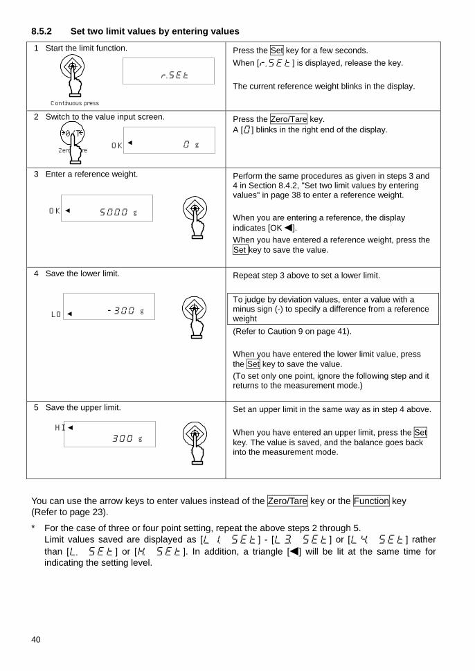
8.5.2 Set two limit values by entering values
1 Start the limit function.
Press the Set key for a few seconds. When [] is displayed, release the key. The current reference weight blinks in the display.
2 Switch to the value input screen.
Press the Zero/Tare key. A [] blinks in the right end of the display.
3 Enter a reference weight.
Perform the same procedures as given in steps 3 and 4 in Section 8.4.2, "Set two limit values by entering values" in page 38 to enter a reference weight. When you are entering a reference, the display indicates [OK]. When you have entered a reference weight, press the Set key to save the value.
4 Save the lower limit.
Repeat step 3 above to set a lower limit. To judge by deviation values, enter a value with a minus sign (-) to specify a difference from a reference weight (Refer to Caution 9 on page 41). When you have entered the lower limit value, press the Set key to save the value. (To set only one point, ignore the following step and it returns to the measurement mode.)
5 Save the upper limit.
Set an upper limit in the same way as in step 4 above. When you have entered an upper limit, press the Set key. The value is saved, and the balance goes back into the measurement mode.
You can use the arrow keys to enter values instead of the Zero/Tare key or the Function key (Refer to page 23).
* For the case of three or four point setting, repeat the above steps 2 through 5. Limit values saved are displayed as [ ] - [ ] or [ ] rather than [ ] or [ ]. In addition, a triangle [] will be lit at the same time for indicating the setting level.
g
HI
gLO
gOK
gOK
Set
Continuous press
Zero/Tare
0/T
Set
Set
Set

41
Caution:
1. The initial limit values are all zero.
2. You can set separate limit values for the weighing machine, parts counting, percentage weighing, and unit converting functions. However, absolute values and deviation values are saved in the same storage area. So if you switch between absolute values and deviation values, limit values are deleted.
3. When the balance is not in measurement mode, you cannot set limit values by key operation. When a cumulative sum is being displayed, for example, you cannot set limit values.
4. Before you set limit values, adjust the zero-point or set a tare range as required (You can adjust the zero-point or set a tare range in sampling for parts counting or weight percent measuring).
5. You can check limit values by pressing the Set key. The lower limit is displayed after the display indicates [ ], and the upper limit is displayed after [ ]. When you set three or four points, saved limit values are displayed as [ ] - [ ] or [ ] rather than [ ] or [ ].
6. When you made a mistake in an operation, press the Print key. As the operation will be cancelled, start the operation from the beginning.
7. If you press the Function key when a value is blinking in the display, the weight of the sample on the balance is set as an actual sample weight. If you press the Zero/Tare key here, you can now enter a limit value.
8. If the limit value entries are not lined up in the order of magnitude, five triangles [] will be lit regardless of the number of judgment points. Check the values and enter them again.
9. When you enter a limit value, it is treated differently between the two judgment methods. To judge by absolute values, enter limit values directly. On the other hand, to judge by deviation values, you have to specify a range with respect to a reference weight.
(Example)
To set a lower limit of 970.0 g and an upper limit of 1050.0 g with respect to a reference weight of 1000.0 g, enter the limit values as shown below:
Reference Weight Lower Limit Upper Limit
Absolute weight 1000.0 g 970.0 g 1050.0 g
Judgment by absolute values 1000.0 g 970.0 g 1050.0 g
Judgment by deviation values 1000.0 g -30.0 g 50.0 g

42
8.6 Bar Graph for the 2-point Scale You can set two points for the limit function, and display a bar graph to indicate the result in a range specified by the two points.
Except for the gravimeter function, all other functions, i.e., weighing machine, parts counting, percentage weighing, and unit converting functions can support this function.
1 Set Function1
Set the 2-point scale [] for Point Scale [ ], and Bar graph for the 2-point scale [] for How to Display Results [ ] in Function1.
2 Set upper and lower limits.
You can put actual samples on the balance or enter values to set upper and lower limits. You can also judge by absolute values or deviation values.
A bar graph is displayed in one of the following ways:
Bar graph Weight range Description
Lower limit > Weight A bar graph is not displayed.
Lower limit ≤ Weight ≤ Upper limit
A bar graph to indicate the judgment result is displayed.
Weight > Upper limit The whole bar graph is displayed.
Caution: 1. When the lower limit is the same as the upper limit, no bar graph will be displayed.
2. When a 2-point bar graph is being displayed, a normal bar graph to indicate the rate of a weight to the weighing capacity is not displayed.
3. When a 2-point bar graph is being displayed, the limit function does not work.
Hints Different bar graph frames are used depending on whether the balance is in the measurement mode or in the 2-point bar graph display mode, as shown below:
Bar graph frame Balance condition
Measurement mode
2-point bar graph

43
9 Calibration and Span Test for the Balance 9.1 Span Adjustment An electronic balance, which is influenced by the acceleration of gravity, indicates different values depending on the location it is used. For this reason, you should calibrate your balance every time you relocate it. You should also calibrate it after a long time of no use or when it does not indicate correct values.
To calibrate a balance is called span adjustment, which is required for highly accurate measurements.
* You must wait for at least 30 minutes after turning the power on, before performing span adjustment.
9.1.1 Span Adjustment with Built-in Weight (Auto-span Adjustment)
* Only supported by the LN**R series units
1 Set Function1.
Select span adjustment with built-in weight (auto-span adjustment) in Function1 [ ]. Then, press the Set key to return to the weight display.
2 Start span adjustment.
Press the Cal key. The built-in weight is enabled, and automatically starts span adjustment. The display indicates [ ], []*, [ ], [ ], [], and [] in sequence. When span adjustment is completed, the balance goes back to the normal weight display.
* While [] is displayed, the balance is preparing to read the zero point. The remaining time is indicated by the bar graph display. (Displayed with LN2202R, LN3202R, LN4202R)
9.1.2 Span Adjustment with External Weight
1 Set Function1.
Select span adjustment with built-in weight (auto-span adjustment) in Function1 [ ]. Then, press the Set key to return to the weight display.
2 Start span adjustment.
Press the Cal key. The display first indicates [ ], and then [ ], and the balance starts adjusting the zero-point. (If weight error is used, the corresponding weight error entered will be indicated for about 2 seconds.) When the display indicates [ ], put a weight on the pan. The balance starts adjusting the weighing capacity. The display indicates [] and then [] in sequence. When span adjustment is completed, the balance goes back to the normal display.
→0← g
CAL
→0← ○ g
Cal
Cal
→0← ○ g
→0← ○ g

44
9.2 Span Test The purpose of the span test is to check for any offset in the span of the balance with respect to a reference weight. Performing this function will not calibrate the balance.
9.2.1 Span Test with Built-in Weight * Only supported by the LN**R series
1 Set Function1.
Set Function1 with nothing put on the pan. Select span test with built-in weight in Function1 [ ]. Then, press the Set key to return to the weight display.
2 Start the span test.
Press the Cal key. The built-in weight is enabled, and automatically starts a span test. The display indicates [ ], []*, [ ], [ ], [], and an error in sequence. When you press a key, the balance goes back into the measurement mode.
* While [] is displayed, the balance is preparing to read the zero point. The remaining time is indicated by the bar graph display. (Displayed with LN2202R, LN3202R, LN4202R)
9.2.2 Span Test with External Weight 1 Set Function1.
Set Function1 with nothing put on the pan. Select span test with external weight in Function1 [ ]. Then, press the Set key to return to the weight display.
2 Start a span test.
Press the Cal key. The display first indicates [ ], and then [ ], and the balance starts testing the zero-point. (If weight error is used, the corresponding weight error entered will be indicated for about 2 seconds,)
When the display indicates [ ], put a weight on the pan. The balance starts a weighing capacity point test.
The display first indicates [] and then an error. When you press a key, the balance goes back into the measurement mode.
* An error displayed after [] is calculated as shown below:
Error = True value – Current weight A positive value displayed as an error means that the balance indicates a weight lighter than the actual weight.
→0← g
Cal
→0← ○ g
→0← ○ g
CAL
→0← ○ g
Cal

45
9.3 Calibration of Built-in Weight * Only for the LN**R series This is a function to calibrate the built-in weight with an external weight.
1 Set Function2.
Set Function2 with nothing put on the pan. Enable the calibration of built-in weight function in Function2 [ ]. Press the Function key.
2 Start span adjustment.
The display is changed []. Press the Function key while holding down the Zero/Tare key, and release the keys at the same time. The display changes from [] to blinking [ ], and then indicates [ ]. When the display indicates [ ], put a weight on the pan carefully. The display blinks [ ], and then indicates [ ]. When the display is changed from [] to [ ], unload the weight. When calibration is completed, the display indicates [], and the balance goes back to measurement mode.
* While [] is displayed, the balance is preparing to read the zero point. The remaining time is
indicated by the bar graph display. (Displayed with LN2202R, LN3202R, LN4202R)
Hints 1. When you press a key other than the Function key during span adjustment or a span test,
the display indicates [], and the span adjustment or test is cancelled. Then the balance goes back to the normal display.
2. To perform span adjustment or a span test with an external weight, use a weight for calibration that weighs 50% of the weighing capacity or heavier. To calibrate more accurately, use a weight that is close to the weighing capacity.
3. When an error is found in span adjustment or in a span test, the following messages are displayed: (1) []: You used a weight weighing less than 50% of the weighing capacity for
span adjustment. (2) []: An error over 1.0% was detected in span adjustment with an external
weight, or the balance failed. (3) []: Automatic span adjustment was performed with an object put on the pan. (4) []: An error over 1.0% was detected in automatic span adjustment, or the
balance failed. (5) []: Abnormal operation occurred in the internal driving unit during automatic
span adjustment. (Pressing a key when an error message is being displayed moves you back to measurement mode).
* When one of these messages is displayed, calibration will not be performed.
Check that you are using a proper weight, and start span adjustment or a span test again. If span adjustment with a proper weight results in the same error message, contact your local dealer.
CAL

46
10 Date and Time Setup 10.1 Time Setup The time is displayed with a clock [] symbol. Set the time in Hour-Minute-Second format on a 24-hour basis.
1 Display the time.
Press the Function key for a few seconds. When the display is changed from [] to [], release the key.
Press the Function key one time. The display automatically indicates the time after indicating [].
2 Set the time.
Press the Set key. You can change a blinking digit.
Use the Zero/Tare key to change the blinking digit. Use the Function key to blink the next digit to the right. If you press the Function key when the rightmost digit is blinking, the leftmost digit blinks.
3 Save the time.
Press the Set key to save the settings. The changes are saved, and a date is displayed.
When you press the Print key before saving a time, the original time is displayed.
30-sec adjustment function Press the Zero/Tare key when the time is being displayed. 29 or fewer seconds are rounded down to the nearest minute, and 30 or more seconds are rounded up to the nearest minute.
10.2 Date Setup A date is displayed with a clock [] symbol. The last two digits of the year are displayed. You can change the date format in Function1.
1 Display the date.
Follow step 1 in 10.1 to change the display to []. (Go straight to step 2 if you set a date after completing steps in 10.1.)
Press the Function key twice. The display automatically indicates a date after indicating [].
2 Set a date. Press the Set key. You can change a blinking digit.
Use the Zero/Tare key to change the blinking digit. Use the Function key to blink the next digit to the right. If you press the Function key when the rightmost digit is blinking, the leftmost digit blinks.
3 Save the date. Press the Set key to save the settings. The changes are saved, and the balance goes back into measurement mode.
When you press the Print key before saving a date, the original date is displayed.
::
指を離す
Continuous press
Key released
Set
Function
Set
Function
指を離す
Press twice
Key released
Continuous press
Set
Set
FunctionFunction

47
11 Various Functions 11.1 Auto Sleep Function This is a function to turn off the display when the balance is left to stand in measurement mode for about 3 minutes. This function can only be used when the balance is operated on the AC adapter. To use the auto sleep function, enable it in Function1 [ ]. When the auto sleep function is enabled, the Sleep lamp (LED) lights up. To exit the sleep mode, touch the pan or press a key.
Caution: The auto sleep function does not work under the following conditions:
1. You are setting Function1, Function2, time or date, or the interval function. 2. An object is put on the pan, and the display is not stable. 3. The balance is operated on batteries.
11.2 Auto Power Off Function This is a function to turn off the balance when the balance is left to stand in measurement mode for about 3 minutes. This function can only be used when the balance is operated on batteries. This function saves battery capacity.
To use this function, enable it in Function1 [ ].
Caution: The auto power off function does not work under the following conditions:
1. You are setting Function1, Function 2, time or date, or the interval function. 2. An object is put on the pan, and the display is not stable. 3. The balance is operated on the AC adapter.
11.3 Set Unit Function This is a function to allow you to select two units (unit A and unit B) and switch between the units.
Which unit to display can be set in Function1. You can also set the same unit for unit A and unit B.
Pressing the Function key switches the unit between unit A and unit B.
Caution: To use unit B, select the weighing machine function in Function1 [ ]. Unit A can be used in all the measurement types of the balance.
11.4 Minimum Readability Setting Function This is a function to change the minimum readability. Set a minimum readability in Function1. When you set a rougher or larger minimum readability, weighing is performed faster. The minimum readability depends on the unit.
You can also set the same unit for unit A and unit B in 11.3, and switch the minimum readability between unit A and unit B.
* The least significant digit cannot be set higher than the 10's digit.

48
11.5 Advice CAL Advice CAL blinks the CAL sign in the display to inform you when span adjustment is to be made. The timing to perform span adjustment depends on changes in ambient temperature and used hours. To use this function, set Function1 to [ ]. When the CAL sign starts to blink, perform span adjustment as soon as possible.
11.6 Date Display This is a function to set the date format to be displayed in the balance or output to a printer. Set date format in Function1 appropriately as shown below:
Output in Year-Month-Day format.
Output in Month-Day-Year format. Date Display
Output in Day-Month-Year format.
11.7 Time Stamp Output This is a function to output measurement data with the current time. You should set the time before this function is used.
To use this function, enable it in Function1 [ ].
11.8 Save Tare Weight Function This is a function to use the latest tare weight when the On/Off key is pressed to turn on the balance. Use this function when you turn the balance on or off with a sample and tare put on the pan.
To use this function, enable it in Function1 [ ]. The saved tare weight is updated every time a tare range is set.
Caution: Leaving the balance loaded with a substance and tare for a long period may result in a larger error in weighing. You should set the tare range regularly.
11.9 Direct Start Function This is a function to turn on the balance automatically when it is connected to the AC power. You can use this function when the balance is used in conjunction with other devices. To use this function, enable it in Function1 [ ].
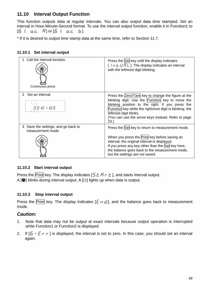
49
11.10 Interval Output Function This function outputs data at regular intervals. You can also output data time stamped. Set an interval in Hour-Minute-Second format. To use the interval output function, enable it in Function1 to [ ] or [ ].
* If it is desired to output time stamp data at the same time, refer to Section 11.7.
11.10.1 Set interval output
1 Call the interval function.
Press the Set key until the display indicates []. The display indicates an interval with the leftmost digit blinking.
2 Set an interval.
Press the Zero/Tare key to change the figure at the blinking digit. Use the Function key to move the blinking position to the right. If you press the Function key while the rightmost digit is blinking, the leftmost digit blinks. (You can use the arrow keys instead. Refer to page 23.)
3 Save the settings, and go back to measurement mode.
Press the Set key to return to measurement mode. When you press the Print key before saving an interval, the original interval is displayed. If you press any key other than the Set key here, the balance goes back to the measurement mode, but the settings are not saved.
11.10.2 Start interval output
Press the Print key. The display indicates [], and starts interval output. A [] blinks during interval output. A [] lights up when data is output.
11.10.3 Stop interval output
Press the Print key. The display indicates [], and the balance goes back to measurement mode.
Caution: 1. Note that data may not be output at exact intervals because output operation is interrupted
while Function1 or Function2 is displayed.
2. If [] is displayed, the interval is set to zero. In this case, you should set an interval again.
::
Continuous press
Set
Set
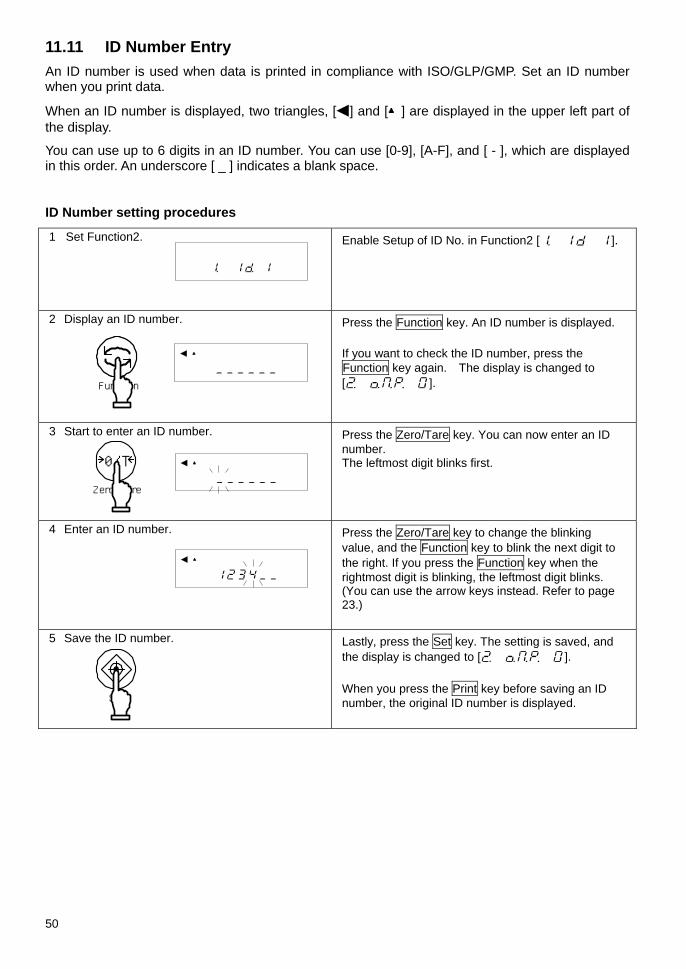
50
11.11 ID Number Entry An ID number is used when data is printed in compliance with ISO/GLP/GMP. Set an ID number when you print data.
When an ID number is displayed, two triangles, [] and [▲] are displayed in the upper left part of the display.
You can use up to 6 digits in an ID number. You can use [0-9], [A-F], and [ - ], which are displayed in this order. An underscore [ _ ] indicates a blank space.
ID Number setting procedures
1 Set Function2.
Enable Setup of ID No. in Function2 [ ].
2 Display an ID number.
Press the Function key. An ID number is displayed. If you want to check the ID number, press the Function key again. The display is changed to [ ].
3 Start to enter an ID number.
Press the Zero/Tare key. You can now enter an ID number. The leftmost digit blinks first.
4 Enter an ID number.
Press the Zero/Tare key to change the blinking value, and the Function key to blink the next digit to the right. If you press the Function key when the rightmost digit is blinking, the leftmost digit blinks. (You can use the arrow keys instead. Refer to page 23.)
5 Save the ID number.
Lastly, press the Set key. The setting is saved, and the display is changed to [ ]. When you press the Print key before saving an ID number, the original ID number is displayed.
▲
▲
▲
Function
Set
Zero/Tare
0/T

51
11.12 Entry of Weight Error By entering the weight error of an external reference weight to be used in span adjustment or span test, a more accurate calibration can be performed. Enter the weight error obtained from the following equation: (Weight errors are entered in the unit of mg.)
Weight Error = Actual Weight - Nominal Value
Example: For a 1000 g weight, a weight error may be = 1000.00012 − 1000 = 0.00012 = +0.12 mg
1 Set Function2.
Set Function2 to [ ].
2 Display the weight error.
Press the Function key. The display shows a weight error. If you are only to check the weight error value, press the Function key again. The display is changed to [ ] or [ ] for the next item.
3 Start entering the weight error.
Press the Zero/Tare key. You can now enter the weight error. The leftmost digit blinks first.
4 Entry of weight error.
Press the Zero/Tare key to change the blinking value, and the Function key to blink the next digit to the right. If you press the Function key when the rightmost digit is blinking, the leftmost digit blinks. (You can use the arrow keys instead. Refer to page 23.)
5 Save the weight error data.
Lastly, press the Set key. The setting is saved, and the display is changed to [ ] or [ ] for the next item. If you press the Print key during the entry, the display returns to the previous weight error value.
6 Use the weight error.
For using the weight error entered, set to [ ].
Hints
If more than one weight is used in combination, enter the total error of the weights to be used.
The range of the weight error should be within ±100.00 mg. If any value outside the range is entered, it will result in the display of [].
▲
mg
▲
M mg
⇒⇒⇒~⇒⇒⇒小数点
マイナスMinus
Decimal point●
」
Function
Set
Zero/Tare
0/T

52
12 Input/Output Functions 12.1 RS232C Output 12.1.1 Connector pin numbers and functions
Pin No. Signal Name Input/Output Function & Remarks
1 - - -
2 RXD Input Receiving data
3 TXD Output Transmitting data
4 DTR Output HIGH (When the balance is powered ON)
5 GND - Signal ground
6 - - -
7 - - -
8 - - -
9 - - -
Caution: Be sure to disconnect the AC adapter from the power outlet before plugging or unplugging the connector.
D-SUB9P Male Connector: Rear Panel
1 2 3 4 5
6 7 8 9

53
12.1.2 Connecting the balance to a PC
Sample connection with an IBM-PC/AT compatible machine
Sample wire connection with PC9801
Balance IBM-PC/AT compatible machineD-SUB9PD-SUB9P
TXD
RXD
GND
DCD
RTS
CTS
DSR
DTR
RXD
TXD
GND
3
2
5
1
7
8
6
4
2
3
5
PC9801 Balance D-SUB25P
TXD
RXD
GND
DCD
RTS
CTS
DSR
DTR
RXD
TXD
GND5
3
2
5
20
7
8
6
4
D-SUB9P
2
3
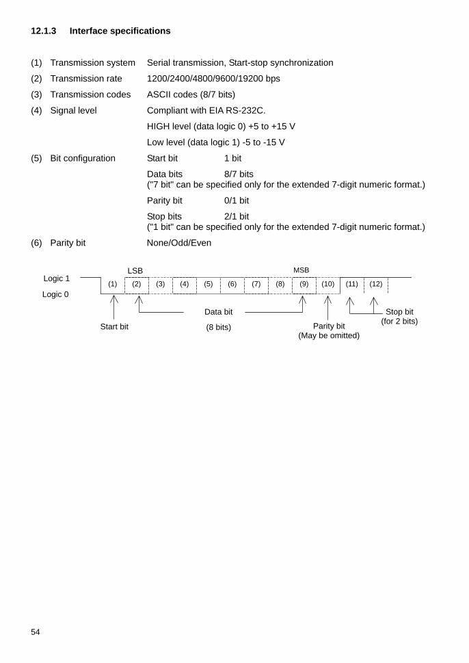
54
12.1.3 Interface specifications
(1) Transmission system Serial transmission, Start-stop synchronization
(2) Transmission rate 1200/2400/4800/9600/19200 bps
(3) Transmission codes ASCII codes (8/7 bits)
(4) Signal level Compliant with EIA RS-232C.
HIGH level (data logic 0) +5 to +15 V
Low level (data logic 1) -5 to -15 V
(5) Bit configuration Start bit 1 bit
Data bits 8/7 bits ("7 bit" can be specified only for the extended 7-digit numeric format.)
Parity bit 0/1 bit
Stop bits 2/1 bit ("1 bit" can be specified only for the extended 7-digit numeric format.)
(6) Parity bit None/Odd/Even
(1) (2) (3) (4) (5) (6) (7) (8) (9) (10) (11) (12) Logic 0
MSB LSB Logic 1
Stop bit (for 2 bits)
Data bit
Start bit (8 bits) Parity bit (May be omitted)

55
12.2 Output to Peripherals Our standard peripheral units can be connected to the balance. *1
These peripheral units include: CSP-160, CSP-240
12.2.1 Connector pin numbers and functions
Pin No. Signal Name Input/Output Function & Remarks
1 EXT.TARE Input Tare setting from an external device *2
2 - - - 3 - - - 4 TXD Output Transmitting data 5 GND - Signal ground
6 - - - 7 - - - 8 - - -
*1 To connect a peripheral unit to the balance, use the connection cable supplied with the unit.
*2 You can set a tare range or adjust the zero-point. from an external device by connecting a contact or a transistor switch between pin 1 and pin 5. In this case, allow at least 400 ms for connection (ON) time (Maximum voltage when the balance is turned OFF: 15 V, sink current when it is turned ON: 20 mA).
Caution: Be sure to disconnect the AC adapter from the power outlet before plugging or unplugging the connector.
DIN8P connector for output to peripheral devices
1
2
3
45
67 8

56
12.3 Type of Communication Texts This interface function uses the following three types of communication texts:
(1) Output data Data, such as weight values, that is output from the balance to an external unit
(2) Input commands Commands to control the balance from an external unit (3) Response Response that is output from the balance to an input command
Caution: 1. All of these communication texts can be used for RS232C output. 2. Only output data (1) can be used for a peripheral output unit.
12.4 Output Data You can select one from the following three formats in Function1:
12.4.1 Data format
(1) 6-digit numeric format
Consists of 14 characters including terminators (CR=0DH, LF=0AH).
1 2 3 4 5 6 7 8 9 10 11 12 13 14
P1 D1 D2 D3 D4 D5 D6 D7 U1 U2 S1 S2 CR LF
(2) 7-digit numeric format
Consists of 15 characters including terminators (CR=0DH, LF=0AH). A parity bit can be appended.
1 2 3 4 5 6 7 8 9 10 11 12 13 14 15
P1 D1 D2 D3 D4 D5 D6 D7 D8 U1 U2 S1 S2 CR LF
(3) Extended 7-digit numeric format
Consists of 15 characters including terminators (CR, LF). A parity bit can be appended.
This is an extended version of the 7-digit numeric format. The extended version is different from the 7-digit numeric format in that:
the data length can be 7 bits rather than 8 bits, and
the stop bit may be set to 1 bit rather than 2 bits.
The extended version is the same as the normal 7-digit format in other bits. However, if you select Japanese (Katakana) for Printed Language [ ] in Function1, the data length is forced into 8 bits.
12.4.2 Polarity (P1: 1 character)
P1 Code Description + 2BH When data is 0 or positive. - 2DH When data is negative.

57
12.4.3 Numeric data
6-digit numeric format: (D1-D7: 7 characters)
7-digit numeric format: (D1-D8: 8 characters)
D1 to D7(D8) Code Description 0 – 9 30H to 39H Digits 0 – 9
2EH
* Decimal point (floating) * Omitted when numeric data does not contain decimal
places. In this case, space is output to the least significant digit.
SP (space) 20H
* A space heading a numeric value * When numeric data does not contain decimal places,
space rather than a decimal point is output to the least significant digit *1.
*1 A numeric value is headed by 0 (30H) by factory default setting. You can change the function setting so that it is headed by space (20H) rather than 0.
12.4.4 Unit (U1, U2: 2 characters)
* Codes are all in ASCII codes.
U1 U2 Code Meaning Balance indicators
(SP) G 20H 47H gram g
K G 4BH 47H Kilogram kg
C T 43H 54H carat
O Z 4FH 5AH ounce
L B 4CH 42H pound
O T 4FH 54H troy ounce
D W 44H 57H pennyweight
G R 4BH 52H Grain GN
T L 54H 4CH tael (Hong Kong)
T L 54H 4CH tael (Singapore, Malaysia) Top right
T L 54H 4CH tael (Taiwan) Middle right
M O 4DH 4FH momme mom
t o 74H 6FH tola
P C 50H 43H Pieces Pcs
(SP) % 20H 25H Percentage %
(SP) # 20H 23H Computation results, numbers, etc. #

58
12.4.5 Judgment result when the limit function is enabled (S1: 1 character)
S1 Code Description
L 4CH Too little (LO)
G 47H Proper (OK)
H 48H Too much (HI)
1- or 2-point scale
1 31H Rank 1 2 32H Rank 2 3 33H Rank 3
4 34H Rank 4
5 35H Rank 5
3- or 4-point scale
T 54H Cumulative value U 55H Unit weight
(SP) 20H No judgment result or no data type specified
d 64H Gross
Data type
12.4.6 Status (S2:1 character)
S2 Code Description
S 53H Data stable *
U 55H Data unstable *
E 45H Data error (Indicates that data other than S2 is invalid.)
( [], [] )
(SP) 20H No status specified
* Data that is independent of whether the weighing condition is stable or not, such as cumulative values and unit weights, is independent of whether S2 is S or U when it is output.
12.4.7 Output data other than measurement data
The following data is accompanied by our proprietary printer control commands prior to and after the data when output.
(1) Interval output When each interval output is started or stopped, a header and a footer are output.
Header "-" is output for 15 characters.
1 2 3 4 5 6 7 8 9 10 11 12 13 14 15 - - - - - - - - - - - - - - -
Footer
Two linefeeds are inserted.
(2) Time output When the time stamp function is enabled, the time is output one line above the output data.
1 2 3 4 5 6 7 8 h h : m m : s s
* hh: hour (00-23), mm: minute (00-59), ss: second (00-59)

59
12.5 Input Commands The following 7 input commands are supported:
(1) Tare range command (2) Set output control command
(3) Set measurement mode command (4) Request date output command
(5) Request time output command (6) Set interval command
(7) Span adjustment/test command
12.5.1 Procedure for transmission
(1) An input command is sent from an external device.
The full-duplex transmission system allows you to send an input command at any time independently of the data transmit timing of the balance.
(2) Upon successful completion of an input command, the balance will send out either a normal completion response or the data requested by the command. If the operation has not resulted in normal completion, or if the received input command is invalid (in error), the balance will transmit an error response.
When the balance is in normal display mode, it usually sends a response to an input command within one second after it is received.
However, if the balance receives a tare range command when the Set Tare function is set so that the display is reset to 0 when the balance is stabilized after the Zero/Tare key is pressed, or if it receives an input command that takes a long time, it sends a response after the command is completely processed.
If the balance receives an input command when you are setting a function, when it is under span adjustment, or it is busy for other reasons, it sends a response after that operation is completed.
1) Commands to which a response is sent back after a specified operation is executed:
• Tare range command, span adjustment/test command
2) Commands to which a response is sent back immediately or in 1 second after they are received:
• Commands other than those specified in 1) above
3) Once you have sent an input command from an external device, do not send another input command to the balance until the external device receives a response to the command from the balance.

60
12.5.2 Response
You can select the response format of either the A00/Exx format or the ACK/NAK format in Function1.
(1) A00/Exx format
Consists of 5 characters including terminators (CR, LF).
1 2 3 4 5
A1 A2 A3 CR LF
Response types
A1 A2 A3 Code Meaning
A 0 0 41H 30H 30H Successful completion
E 0 1 45H 30H 31H * Command error (when an errant command is received)
E 0 - 9 0 - 9 45H 30H
39H
30H
39H
(Errors other than E01) * Numeric format error * Processing interrupted * Processing terminated abnormally * Other errors
(2) ACK/NAK format
Consists of 1 character (Does not contain a terminator).
1
A1
Response types
A1 Code Meaning
ACK 06H Successful completion
NAK 15H
* Command error (when an errant command is received)
* Numeric format error * Processing interrupted * Processing terminated abnormally * Other errors
* The following descriptions and tables assume that the A00/Exx format is selected as the response format.
Think of A00 as ACK, and E00 as NAK.

61
12.5.3 Command format
(1) Tare range (zero-setting) command
C1 C2 Code Description Value Response
T (SP) 54H 20H
• Set Tare Range
• Adjust the zero-point
None
A00: Successful completion E01: Command error E04: A tare range cannot be
set or the zero-point cannot be adjusted (because of a range violation or a weight error).
(2) Set output control command
C1 C2 Code Description
0 0 4FH 30H Stop output
0 1 4FH 31H Output continuously at all times
0 2 4FH 32H Output continuously if stable (Stop output if unstable)
0 3 4FH 33H Output once when the Print key is pressed (whether the balance is stable or unstable).
0 4 4FH 34H
Output once when the balance is stable. After any sample is lifted causing the display to show zero or less value, outputs the next time any sample is put on again and the balance is stabilized.
0 5 4FH 35H
Output once when the balance is stable. Stop output when unstable. Output once when the balance is stabilized again (the output includes zero) even if it is not reloaded.
0 6 4FH 36H
Output once when the balance is stable. Output continuously when unstable. Output is stopped after a single output when the balance is stable even if it is not reloaded.
0 7 4FH 37H Output once when the Print key is pressed if the balance is stable.
0 8 4FH 38H Output once immediately
0 9 4FH 39H Output once after stabilized
0 A 4FH 41H Interval function (Output once each time the output time elapses.)
0 B 4FH 42H Interval function (Output once if stable each time the output time elapses.)
A00: Successful completion
E01: Command error
E02: Interval time error
(only with OA or OB)
* Commands O0 to O7 control output in the same way as the settings in Function1. * Commands O8 and O9 are used to request data from the balance. * Once executed, O0 to O7, OA, or OB commands is held until the next command is input.
However, output control is reset to the function setting when the balance is turned on again. * When command OA or OB is input, the balance initiates the interval function, and when the
same command is input again, it terminates the function. * Once either an O8 or O9 command is executed, it returns to the state of "O0".

62
12.5.4 Set measurement mode command
Command Main Body 1st
character 2nd
character Code Description Value Response
M 1 4DH 31H Set to Mode 1 M 2 4DH 32H Set to Mode 2 M 3 4DH 33H Set to Mode 3
M 4 4DH 34H Set to Mode 4
None
A00: Successful completion
E01: Command error
E02: (error)
* The measurement mode to be activated by the above mode settings 1 to 4 depends on the weighing mode currently in use.
Mode
setting Weighing machine
Parts counting
Percentage weighing
Unit converting
Gravimeter / Statistics function
Mode 1 Weight measuring
Weight measuring
Weight measuring
Weight measuring (Error)
Mode 2 Gross weight display Parts counting Percent
measuring Coefficient multiplying (Error)
Mode 3 Cumulative weight *1
Cumulative count display *1
Cumulative percent display *1
Cumulative sum *1 (Error)
Mode 4 Display in unit B *2
Average unit weight (Error) (Error) (Error)
*1 Mode 3 (M3) can be specified only when the addition function is to be used. If the addition function is not enabled, it results in an error.
*2 If a unit is not specified for unit B, the balance is set for the weight measuring mode. When you specify a mode that is not supported by the current Weighing Mode, an error is returned from the balance.
12.5.5 Request date or time output command
Command Main Body 1st
character 2nd
character Code Description Value Response
D D 44H 44H Date output request
D T 44H 54H Time output request
None A00: Successful
completion E01: Command error
(1) Date format
DATE:yyyy.mm.dd(CR)(LF) English ヒヅケ:yyyy.mm.dd(CR)(LF) Japanese (Katakana)
(2) Time data
TIME:(SP)(SP)(SP)(SP)(SP)hh:mm(CR)(LF) English ジコク:(SP)(SP)(SP)(SP)(SP)hh:mm(CR)(LF) Japanese (Katakana)
The above data is accompanied by a control command of our printer when output.
*1 You can select whether you want to output data in English or in Japanese (katakana) in the Printed Language [ ] Function setting.
*2 Date format depends on the setting of Date Display in Function1 [ ].
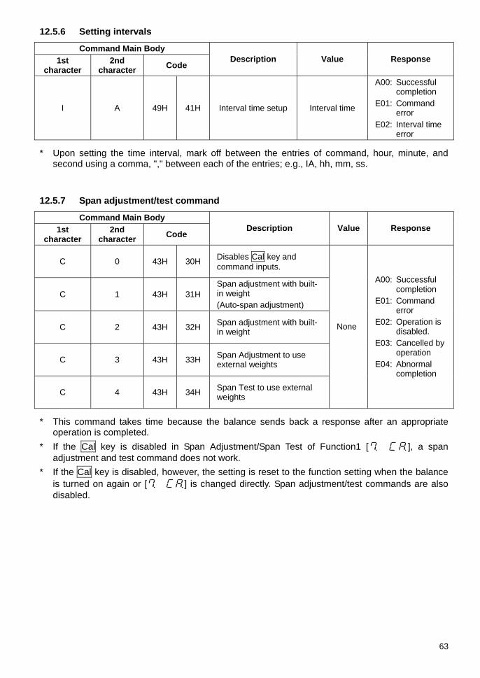
63
12.5.6 Setting intervals
Command Main Body 1st
character 2nd
character Code Description Value Response
I A 49H 41H Interval time setup Interval time
A00: Successful completion
E01: Command error
E02: Interval time error
* Upon setting the time interval, mark off between the entries of command, hour, minute, and
second using a comma, "," between each of the entries; e.g., IA, hh, mm, ss.
12.5.7 Span adjustment/test command
Command Main Body 1st
character 2nd
character Code Description Value Response
C 0 43H 30H Disables Cal key and command inputs.
C 1 43H 31H Span adjustment with built-in weight (Auto-span adjustment)
C 2 43H 32H Span adjustment with built-in weight
C 3 43H 33H Span Adjustment to use external weights
C 4 43H 34H Span Test to use external weights
None
A00: Successful completion
E01: Command error
E02: Operation is disabled.
E03: Cancelled by operation
E04: Abnormal completion
* This command takes time because the balance sends back a response after an appropriate
operation is completed. * If the Cal key is disabled in Span Adjustment/Span Test of Function1 [ ], a span
adjustment and test command does not work. * If the Cal key is disabled, however, the setting is reset to the function setting when the balance
is turned on again or [ ] is changed directly. Span adjustment/test commands are also disabled.
64
12.5.8 Setting limit values
Command Main Body first
character second
character ASCII code Description Value Response
L A 4CH 41H First setting point/lower limit
L B 4CH 42H Second setting point/upper limit
L C 4CH 43H Reference value L D 4CH 44H Third setting point L E 4CH 45H Forth setting point
Limit values
A00: Successful completion
E01:Command error E02:Set value error
Caution 1. Insert a comma between command entries and limit values; e.g., LA, nnn.
2. Enter numerical values only. You do not need to enter units.
3. In weighing machine mode, the unit set in Unit A is applied to the entered value. For example, when “LA, 20.00” is transmitted, it is recognized as 20.00 g if gram is selected in Unit A, and 20.00 ct if carat is selected in Unit A.
4. The units used for parts counting, percentage weighing, and unit converting are PCS, %, and # respectively.
12.5.9 Sample input commands
T(SP)(CR)(LF) Set tare range or adjust to zero-point. O1(CR)(LF) Set the balance to continuous output. O8(CR)(LF) Output data (once immediately). IA,01,30,00(CR)(LF) Set an interval of 01 hrs: 30 min: 00 sec. OA(CR)(LF) Start the interval function. DD(CR)(LF) Output the date. DT(CR)(LF) Output the time. LA,80.5(CR)(LF) Set the first setting point to 80.5.
(The unit varies depending on the weighing mode.)

65
12.6 Special Format Output 12.6.1 Special format 1
This output format is applied when [ ] is selected in Function1
1 2 3 4 5 6 7 8 9 10 11 12 13 14 15 16 P1 SP D1 D2 D3 D4 D5 D6 D7 D8 SP U1 U2 U3 CR LF
Set
val
ue
erro
r
Spac
e
Measurement data (including decimal point)
Spac
e
Unit Terminator
P1 (One character): Set value error Polarity plus/zero: [+] (2BH), Minus: [-] (2DH) SP (One character): Space [ ] (20H) D1~D8 (Eight character): Measurement data,
numerical value [0 to 9] (30H–39H), and decimal point (2EH) * Numerical values are right-aligned.
A space (20H) is used when there is no numerical value. SP (One character): Space [ ] (20H) U1~U3 (Three character): Unit
Unit Output ASCII code g g (67H) (20H) (20H) kg kg (6BH) (67H) (20H) carat ct (63H) (74H) (20H) ounce oz (6FH) (7AH) (20H) pound lb (6CH) (62H) (20H) troy ounce ozt (6FH) (7AH) (74H) penny weight dwt (64H) (77H) (74H) grain GN (47H) (4EH) (20H) tael(Hong Kong) tlh (74H) (6CH) (68H) tael(SG) tls (74H) (6CH) (73H) tael(Taiwan) tlt (74H) (6CH) (74H) momme mom (6DH) (6FH) (6DH) tola tol (74H) (6FH) (6CH) parts counting pcs (70H) (63H) (73H) percentage weighing % (25H) (20H) (20H) unit converting # (23H) (20H) (20H)
* When the output is unstable, a unit (three characters) may be a space (20H). <CR><LF>: terminator
Example:
[g] : + 123.456 g <CR><LF>
[] : H <CR><LF>
[] : L <CR><LF> six characters seven characters
(**H) : ASCII code : Space

66
12.6.2 Special format 2
This output format is applied when [ ] is selected in Function1.
1 2 3 4 5 6 7 8 9 10 11 12 13 14 15 16 17 18 19 20
S1 S2 S3 SP D1 D2 D3 D4 D5 D6 D7 D8 D9 D10 SP U1 U2 U3 CR LF
Stability information Sp
ace Measurement data (including polarity and decimal
point) Spac
e Unit (One to three characters)
Termi- nator
S1~S3 (three character): Stable: [S S] (53H) (20H) (53H), Unstable: [S D]: (53H)
(20H) (44H) SP (One character): Space [ ](20H) D1~D10 (10 character): Set value error Polarity plus/zero: Space [ ] (20H), Minus: [-]
(2DH) numerical value [0 to 9] (30H–39H), and decimal point (2EH)
* Numerical values are right-aligned. A space (20H) is used when there is no numerical value.
SP(One character):Space[ ](20H) U1~U3 (One to three character): Unit
Unit Output ASCII code g g (67H) kg kg (6BH)(67H) carat ct (63H) (74H) ounce oz (6FH) (7AH) pound lb (6CH) (62H) troy ounce ozt (6FH) (7AH) (74H) penny weight dwt (64H) (77H) (74H) grain gr (67H) (72H) tael(Hong Kong) tlh (74H) (6CH) (68H) tael(SG) tls (74H) (6CH) (73H) tael(Taiwan) tlt (74H) (6CH) (74H) momme mom (6DH) (6FH) (6DH) tola tla (74H) (6CH) (61H) parts counting pcs (70H) (63H) (73H) percentage weighing % (25H) unit converting # (23H)
* This format has a variable length, with the number of characters varying from one to three depending on the unit.
<CR><LF>: terminator
Example:
[g] : S S 123.456 g<CR><LF>
[] : S +<CR><LF>
[] : S -<CR><LF>
(**H) : ASCII code : Space

67
13 Use Printers 13.1 Printer Setting (1) Use CSP-160 or CSP-240 with the balance.
(2) Set proper print functions (print control) with the balance referring to the instruction manual for your printer. The factory default of our printer is manual printing (printer control).
(3) Make the baud rate and other settings compatible between the balance and the printer.
13.2 Saving CAL and span test results 1 Set Function1.
Set the ISO/GLP/GMP compatible item to [ ] and set the GLP compatible item for measurement data to [ ].
Then, press the Set key to return to the weight display.
2 Performs span adjustment/span test.
During output, it indicates [ ] or an error display and it looks like the balance is frozen. However, this is a normal operation. Wait until the output operation is completed.
13.3 Measurement Data Output in Compliance with ISO/GLP/GMP 1 Set Function1.
Set the ISO/GLP/GMP compatible item to [ ] and set the GLP compatible item for measurement data to [ ]. Then, press the Set key to return to the weight display.
2 Header output
Press and hold the Print key for a while.
The display indicates [] and a header is output.
3 Measurement data output
Measurement data can be output at any time during measurements.
4 Footer output
Press and hold the Print key for a while after the measurement is completed.
The display indicates [] and a footer is output.
Caution (1) Upon printing calibration/span test results or ISO/GLP/GMP compatible outputs, date and time
data is also printed. Check the date and time set in the balance before printing. (Refer to Section 10: Date and Time Setup in page 40).
(2) Do not press any keys on the printer during printing. * Refer to Section 14 "Output in Compliance with ISO/GLP/GMP" described from page 68 for
sample prints.
Continuous press
Continuous press

68
14 Output in Compliance with ISO/GLP/GMP When a span adjustment or span test is successfully completed, the balance presents the results according to the following format. If span adjustment or a span test is not completed successfully, no data will be printed. The "X" entries in the following tables will vary with the model or the weight used. The line of external weight “ERR” or weight error is printed only when weight error is used according to the Function2 setting.
(1) Span adjustment with the built-in weight (auto-span adjustment)
(2) Span adjustment with an external weight
English Japanese (Katakana)
English Japanese (Katakana) 1 2 3 4 5 6 7 8 9 10 11 12 13 14 15
1
2 * * C A L I B R A T I O N * *3
4 D A T E : 2 1 . 0 9 . 2 0 1 05 T I M E : 1 6 : 5 66 S H I N K O D E N S H I7 T Y P E :8 X X X X X X X X L N 4 2 0 2 R9 S / N : X X X X X X X X X X10 I D : X X X X X X11
12 C A L . I N T E R N A L13 R E F :14 X X X X X X X X X X g15
16 C O M P L E T E17 D A T E : 2 1 . 0 9 . 2 0 1 018 T I M E : 1 6 : 5 719
20 S I G N A T U R E21
22
23
24 * * * * * * * * * * * * * * *25
26
27
28
1 2 3 4 5 6 7 8 9 10 11 12 13 14 15
1
2 * * * コ ウ セ イ * * *3
4 ヒ ツ " ケ : 2 0 1 0 . 0 9 . 2 15 シ " コ ク : 1 6 : 5 66 S H I N K O D E N S H I7 カ タ シ キ :8 X X X X X X X X L N 4 2 0 2 R9 セ イ ハ " ン X X X X X X X X X X10 I D : X X X X X X11
12 コ ウ セ イ ( ナ イ フ " フ ン ト " ウ )13 キ シ " ュ ン :14 X X X X X X X X X X g15
16 シ ュ ウ リ ョ ウ17 ヒ ツ " ケ : 2 0 1 0 . 0 9 . 2 118 シ " コ ク : 1 6 : 5 719
20 シ ョ メ イ21
22
23
24 * * * * * * * * * * * * * * *25
26
27
28
1 2 3 4 5 6 7 8 9 10 11 12 13 14 15
1
2 * * C A L I B R A T I O N * *3
4 D A T E : 2 1 . 0 9 . 2 0 1 05 T I M E : 1 6 : 5 56 S H I N K O D E N S H I7 T Y P E :8 X X X X X X X X L N 4 2 0 2 R9 S / N : X X X X X X X X X X10 I D : X X X X X X11
12 C A L . E X T E R N A L13 R E F :14 X X X X X X X X X X g15
16 C O M P L E T E17 D A T E : 2 1 . 0 9 . 2 0 1 018 T I M E : 1 6 : 5 619
20 S I G N A T U R E21
22
23
24 * * * * * * * * * * * * * * *25
26
27
28
1 2 3 4 5 6 7 8 9 10 11 12 13 14 15
1
2 * * * コ ウ セ イ * * *3
4 ヒ ツ " ケ : 2 0 1 0 . 0 9 . 2 15 シ " コ ク : 1 6 : 5 66 S H I N K O D E N S H I7 カ タ シ キ :8 X X X X X X X X L N 4 2 0 2 R9 セ イ ハ " ン X X X X X X X X X X10 I D : X X X X X X11
12 コ ウ セ イ ( カ " イ フ " フ ン ト " ウ13 キ シ " ュ ン :14 X X X X X X X X X X g15
16 シ ュ ウ リ ョ ウ17 ヒ ツ " ケ : 2 0 1 0 . 0 9 . 2 118 シ " コ ク : 1 6 : 5 719
20 シ ョ メ イ21
22
23
24 * * * * * * * * * * * * * * *25
26
27
28

69
(3) Span test with the built-in weight
(4) Span test with an external weight
1 2 3 4 5 6 7 8 9 10 11 12 13 14 15
1
2 * * C A L . T E S T * * * * *3
4 D A T E : 2 1 . 0 9 . 2 0 1 05 T I M E : 1 6 : 5 66 S H I N K O D E N S H I7 T Y P E :8 X X X X X X X X L N 4 2 0 2 R9 S / N : X X X X X X X X X X10 I D : X X X X X X11
12 C A L . I N T . T E S T13 R E F :14 X X X X X X X X X X g15 D I F F :16 X X X X X X X X X X g17
18 C O M P L E T E19 D A T E : 2 1 . 0 9 . 2 0 1 020 T I M E : 1 6 : 5 721
22 S I G N A T U R E23
24
25
26 * * * * * * * * * * * * * * *27
28
29
30
1 2 3 4 5 6 7 8 9 10 11 12 13 14 15
1
2 * * * テ ス ト * * *3
4 ヒ ツ " ケ : 2 0 1 0 . 0 9 . 2 15 シ " コ ク : 1 6 : 5 66 S H I N K O D E N S H I7 カ タ シ キ :8 X X X X X X X X L N 4 2 0 2 R9 セ イ ハ " ン X X X X X X X X X X10 I D : X X X X X X11
12 テ ス ト ( ナ イ フ " フ ン ト " ウ )13 キ シ " ュ ン :14 X X X X X X X X X X g15 コ " サ :16 X X X X X X X X X X g17
18 シ ュ ウ リ ョ ウ19 ヒ ツ " ケ : 2 0 1 0 . 0 9 . 2 120 シ " コ ク : 1 6 : 5 721
22 シ ョ メ イ23
24
25
26 * * * * * * * * * * * * * * *27
28
29
30
1 2 3 4 5 6 7 8 9 10 11 12 13 14 15
1
2 * * C A L I B R A T I O N * *3
4 D A T E : 2 1 . 0 9 . 2 0 1 05 T I M E : 1 6 : 5 56 S H I N K O D E N S H I7 T Y P E :8 X X X X X X X X L N 4 2 0 2 R9 S / N : X X X X X X X X X X10 I D : X X X X X X11
12 C A L . E X T E R N A L13 R E F :14 X X X X X X X X X X g15
16 C O M P L E T E17 D A T E : 2 1 . 0 9 . 2 0 1 018 T I M E : 1 6 : 5 619
20 S I G N A T U R E21
22
23
24 * * * * * * * * * * * * * * *25
26
27
28
1 2 3 4 5 6 7 8 9 10 11 12 13 14 15
1
2 * * * コ ウ セ イ * * *3
4 ヒ ツ " ケ : 2 1 . 0 9 . 2 0 1 05 シ " コ ク : 1 6 : 5 56 S H I N K O D E N S H I7 カ タ シ キ :8 X X X X X X X X L N 4 2 0 2 R9 セ イ ハ " ン X X X X X X X X X X10 I D : X X X X X X11
12 コ ウ セ イ ( カ " イ フ " フ ン ト " ウ13 キ シ " ュ ン :14 X X X X X X X X X X g15
16 シ ュ ウ リ ョ ウ17 ヒ ツ " ケ : 2 1 . 0 9 . 2 0 1 018 シ " コ ク : 1 6 : 5 619
20 シ ョ メ イ21
22
23
24 * * * * * * * * * * * * * * *25
26
27
28
English Japanese (Katakana)
English Japanese (Katakana)

70
(5) Printing of measurement data
1) Header
2) Footer
(6) Calibration of Built-in Weight
1 2 3 4 5 6 7 8 9 10 11 12 13 14 15
1
2 * * * * R E F . C A L * * * *3
4 D A T E : 2 1 . 0 9 . 2 0 1 05 T I M E : 1 6 : 5 66 S H I N K O D E N S H I7 T Y P E :8 X X X X X X X X L N 4 2 0 2 R9 S / N : X X X X X X X X X X10 I D : X X X X X X11
12 R E F :13 X X X X X X X X X X g14
15 C O M P L E T E16 D A T E : 2 1 . 0 9 . 2 0 1 017 T I M E : 1 6 : 5 818
19 S I G N A T U R E20
21
22
23 * * * * * * * * * * * * * * *24
25
26
27
1 2 3 4 5 6 7 8 9 10 11 12 13 14 15
1
2 S H I N K O D E N S H I3 T Y P E :4 X X X X X X X X L N 4 2 0 2 R5 S / N : X X X X X X X X X X6 I D : X X X X X X7
8 S T A R T9 D A T E : 2 2 . 0 9 . 2 0 1 010 T I M E : 1 3 : 0 011
1 2 3 4 5 6 7 8 9 10 11 12 13 14 15
1
2 E N D3 D A T E : 2 2 . 0 9 . 2 0 1 04 T I M E : 1 6 : 0 05
6 S I G N A T U R E7
8
9
10 * * * * * * * * * * * * * * *11
12
13
14
1 2 3 4 5 6 7 8 9 10 11 12 13 14 15
1
2 シ ュ ウ リ ョ ウ3 ヒ ツ " ケ : 2 0 1 0 . 0 9 . 2 24 シ " コ ク : 1 6 : 0 05
6 シ ョ メ イ7
8
9
10 * * * * * * * * * * * * * * *11
12
13
14
1 2 3 4 5 6 7 8 9 10 11 12 13 14 15
1
2 S H I N K O D E N S H I3 カ タ シ キ :4 X X X X X X X X L N 4 2 0 2 R5 セ イ ハ " ン X X X X X X X X X X6 I D : X X X X X X7
8 カ イ シ9 ヒ ツ " ケ : 2 0 1 0 . 0 9 . 2 210 シ " コ ク : 1 3 : 0 011
1 2 3 4 5 6 7 8 9 10 11 12 13 14 15
1
2 * ナ イ フ " フ ン ト " ウ コ ウ セ イ *3
4 ヒ ツ " ケ : 2 0 1 0 . 0 9 . 2 15 シ " コ ク : 1 6 : 5 66 S H I N K O D E N S H I7 カ タ シ キ :8 X X X X X X X X L N 4 2 0 2 R9 セ イ ハ " ン X X X X X X X X X X10 I D : X X X X X X11
12 キ シ " ュ ン :13 X X X X X X X X X X g14
15 シ ュ ウ リ ョ ウ16 ヒ ツ " ケ : 2 0 1 0 . 0 9 . 2 117 シ " コ ク : 1 6 : 5 818
19 シ ョ メ イ20
21
22
23 * * * * * * * * * * * * * * *24
25
26
27
English Japanese (Katakana)
English Japanese (Katakana)
English Japanese (Katakana)

71
15 Operate on Batteries This function can only be used with a balance equipped with optional batteries. The battery option is unavailable for LN**R series units.
15.1 Specifications • Built-in batteries
• Charge time: About 15 hours
• Operation time: About 6 hours of continuous operation
• Can be recharged: More than 300 times
15.2 Recharging Batteries • A [ ] icon is displayed when the balance is operated on batteries. As the battery gets
weaker, the sign is changed into [ ] or [ ] (flashing). When the icon changes to [ ] (flashing), follow the steps below to charge the batteries.
(1) Connect the AC adapter supplied with the balance.
(2) Turn the balance off.
(3) Wait about 15 hours until the batteries are fully recharged.
15.3 Precautions Relating to Use 1. Disconnect the AC adapter after the batteries are recharged. The balance operated on
batteries is slightly charged while it is in use (turned on). Do not continue to charge batteries after they are recharged, because that may shorten their life.
2. When you use the balance for the first time after purchase, battery operation time may be shorter than usual because of natural discharge.
3. If nothing is displayed or the display is turned off in a minute after you turn on the balance or the display is turned off after a succession of short beeps, the batteries may be weak. Recharge the batteries or operate the balance on the AC adapter.
Follow the following instructions for safe use:
1. Do not disassemble or modify the batteries. Avoid the reverse wiring of positive and negative poles or a short circuit. Such mishandling may damage the batteries, or cause the balance to fail or ignite.
2. Be sure to use the AC adapter supplied with the balance. A different AC adapter may cause the batteries to generate heat or explode.
3. Do not put the batteries into a fire because they may explode.
注 意! Caution

72
16 Troubleshooting * Parentheses contain a page to refer to.
Symptom Cause Measures to Take
No display • The AC adapter is not connected. • The batteries are exhausted.
→ Ensure that the AC adapter is connected.
→ Recharge the batteries (page 71).
The display is unstable. The display takes time to be stabilized. The display does not move with the M sign flashing.
• The balance is influenced by wind or vibration.
• The balance is placed on an unstable base.
• The pan, tare, or sample put on the balance is in contact with an external object.
→ Read Precautions Relating to Use (pages 2 to 4).
Weight indication contains an error.
• Tare range is set incorrectly. • The adjusters are not settled, and the
balance is not kept horizontal. • The display error is caused because the
balance has not been used for a long period of time or has been relocated to another location.
→ Set the tare range correctly. → Check that the balance is
kept horizontal (page 8). → Perform span adjustment of
the balance (page 43).
[] appears before the capacity is reached.
• The capacity is reached by the weight including the tare weight. (Measurement range is for the sum of container and sample weight.)
• The mechanism section was damaged for some reason.
→ Check the total weight. → Review the container.
[] is displayed.
• There is a foreign object trapped between the pan (or pan base) and the balance.
• The mechanism section was damaged for some reason.
→ Remove the pan and examine the surface on which the pan was placed.
[] is displayed.
• The internal clock has failed. → Contact your local dealer.
[] is displayed. [] is displayed.
• The balance is influenced by static electricity or noise.
• The electric components of the balance have failed.
→ Contact your local dealer.
The display is turned off when the balance is operated on batteries. The [ ] icon blinks. No display
• The display was turned off by the auto power off function.
• The batteries were exhausted.
→ Turn the power on again. Disable the auto power off function if desired (page 47).
→ Recharge the batteries (page 71).
→ Operate the balance on the AC adapter.
[] is displayed.
The built-in weight drive unit has have failed.
→ Contact your local dealer.

73
17 Specifications
17.1 Basic Specifications
LN 223
LN 323
LN 423
LN 623
LN 1202
LN 2202
LN 3202
LN 4202
Model Item
LN 223R
LN 323R
LN 423R
LN 623R
LN 1202R
LN 2202R
LN 3202R
LN 4202R
Weighing capacity [g] 220g 320g 420g 620g 1200g 2200g 3200 4200
Minimum readability [g] 0.001g 0.001g 0.001g 0.001g 0.01g 0.01g 0.01g 0.01g
Parts counting Minimum unit
weight [g] 0.001g 0.001g 0.001g 0.001g 0.01g 0.01g 0.01g 0.01g
Percentage Lower weight
limit [g] 0.1g 0.1g 0.1g 0.1g 1g 1g 1g 1g
Size of measurement
pan 120×140[mm] 200×200[mm]
Span adjustment method
LN series: External weight is used LN**R series: Internal or external weight is used
Model Item
LN 6202
LN 8201
LN 12001
LN 15001
LN 21001
LN 31001
Weighing capacity [g] 6200g 8200g 12000g 15000g 21000g 31000g
Minimum readability [g] 0.01g 0.1g 0.1g 0.1g 0.1g 0.1g
Parts counting Minimum unit
weight [g] 0.01g 0.1g 0.1g 0.1g 0.1g 0.1g
Percentage Lower weight
limit [g] 1g 10g 10g 10g 10g 10g
Size of measurement
pan 200×200[mm] 220×250[mm]
Span adjustment method Span adjustment with external weight

74
17.2 Common Specifications (1) Weight measurement method: ・・・・・・・・Tuning fork system (2) Tare range ・・・・・・・・・・・・・・・・・・・・・・・・・Full capacity (3) Display: ・・・・・・・・・・・・・・・・・・・・・・・・・・・The FIP segment can display up to 8 digits.
The segment is 12.5 mm high, and displays 8 digits for a weight. Can display a bar graph of up to 40 bars and various messages.
(4) Overload display: ・・・・・・・・・・・・・・・・・ [] is displayed when the weighing capacity is exceeded by 9 divisions.
(5) Output: ・・・・・・・・・・・・・・・・・・・・・・・・・・・・Bi-direction RS232C output, output for peripherals (6) Supported printer:・・・・・・・・・・・・・・・・・・・CSP-160, CSP-240 (7) Operation temperature/humidity range: 5 to 35°C, 80%RH or lower (8) AC adapter: ・・・・・・・・・・・・・・・・・・・・・・・・Dedicated AC adapter: 12VDC/120VAC or
12VDC/230VAC (9) Options・・・・・・・・・・・・・・・・・・・・・・・・・・ • Hook for hanging *1
• Battery option *2 • Buzzer option • Limit contact output option • Full pack option • RS422 option *3
*1 For 1200g~15kg Capacity models only.
(Inside is installed hook for under weighing for 220g~620g,21kg and 31kg model.)
*2 unavailable for LN**R series
*3 When the RS422 option is selected, the D-SUB9P connector is replaced with an RS422
connector.

75
17.3 Minimum Display by Unit of Measurement
LN223 LN323 LN423 LN623 LN1202 LN2202 LN3202 LN4202 Model
Unit_of measuremant
LN223R LN323R LN423R LN623R LN1202R LN2202R LN3202R LN4202R
220 320 420 620 1200 2200 3200 4200 g
0.001 0.001 0.001 0.001 0.01 0.01 0.01 0.01 0.22 0.32 0.42 0.62 1.2 2.2 3.2 4.2
kg 0.000001 0.000001 0.000001 0.000001 0.00001 0.00001 0.00001 0.00001 1100 1600 2100 3100 6000 11000 16000 21000
(ct) 0.005 0.005 0.005 0.005 0.05 0.05 0.05 0.05 7.7 11 14 21 42 77 110 140
(oz) 0.00005 0.00005 0.00005 0.00005 0.0005 0.0005 0.0005 0.0005 0.48 0.7 0.92 1.3 2.6 4.8 7 9.2
(lb) 0.000005 0.000005 0.000005 0.000005 0.00005 0.00005 0.00005 0.00005 7 10 13 19 38 70 100 130
(ozt) 0.00005 0.00005 0.00005 0.00005 0.0005 0.0005 0.0005 0.0005 140 200 270 390 770 1400 2000 2700
(dwt) 0.001 0.001 0.001 0.001 0.01 0.01 0.01 0.01 3300 4900 6400 9500 18000 33000 49000 64000
GN (grain) 0.02 0.02 0.02 0.02 0.2 0.2 0.2 0.2 5.8 8.5 11 16 32 58 85 110
(Hong Kong) 0.00005 0.00005 0.00005 0.00005 0.0005 0.0005 0.0005 0.0005 5.8 8.4 11 16 31 58 84 110
(Singapore, Malaysia)
0.00005 0.00005 0.00005 0.00005 0.0005 0.0005 0.0005 0.0005
5.8 8.5 11 16 32 58 85 110 (Taiwan) 0.00005 0.00005 0.00005 0.00005 0.0005 0.0005 0.0005 0.0005
58 85 110 160 320 580 850 1100 mom (momme)
0.0005 0.0005 0.0005 0.0005 0.005 0.005 0.005 0.005 18 27 36 53 100 180 270 360
(to) 0.0001 0.0001 0.0001 0.0001 0.001 0.001 0.001 0.001
* The view of the table
Upper cell: Capacity Lower cell: Readability
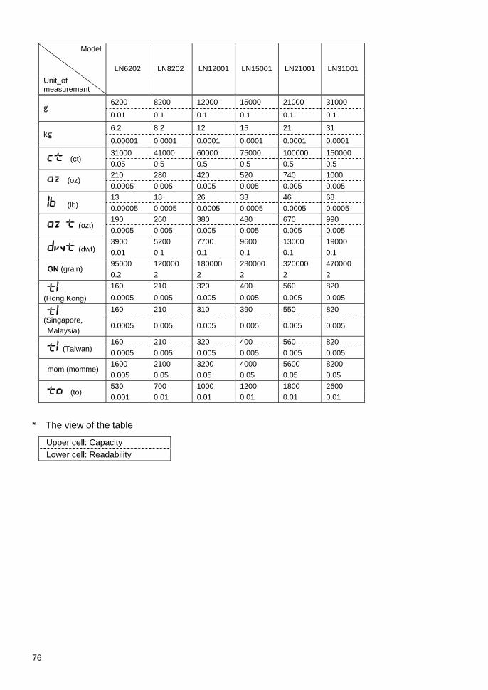
76
Model
Unit_of measuremant
LN6202 LN8202 LN12001 LN15001 LN21001 LN31001
6200 8200 12000 15000 21000 31000 g
0.01 0.1 0.1 0.1 0.1 0.1
6.2 8.2 12 15 21 31 kg
0.00001 0.0001 0.0001 0.0001 0.0001 0.0001 31000 41000 60000 75000 100000 150000
(ct) 0.05 0.5 0.5 0.5 0.5 0.5 210 280 420 520 740 1000
(oz) 0.0005 0.005 0.005 0.005 0.005 0.005 13 18 26 33 46 68
(lb) 0.00005 0.0005 0.0005 0.0005 0.0005 0.0005 190 260 380 480 670 990
(ozt) 0.0005 0.005 0.005 0.005 0.005 0.005 3900 5200 7700 9600 13000 19000
(dwt) 0.01 0.1 0.1 0.1 0.1 0.1 95000 120000 180000 230000 320000 470000
GN (grain) 0.2 2 2 2 2 2 160 210 320 400 560 820
(Hong Kong) 0.0005 0.005 0.005 0.005 0.005 0.005 160 210 310 390 550 820
(Singapore, Malaysia)
0.0005 0.005 0.005 0.005 0.005 0.005
160 210 320 400 560 820 (Taiwan) 0.0005 0.005 0.005 0.005 0.005 0.005
1600 2100 3200 4000 5600 8200 mom (momme)
0.005 0.05 0.05 0.05 0.05 0.05 530 700 1000 1200 1800 2600
(to) 0.001 0.01 0.01 0.01 0.01 0.01
* The view of the table
Upper cell: Capacity Lower cell: Readability

77
18 Conversion Table of Units
Unit Gram carat Ounce Pound troy ounce Penny Weight
1g 1 5 0.03527 0.00220 0.03215 0.64301 1ct 0.2 1 0.00705 0.00044 0.00643 0.12860 1oz 28.34952 141.74762 1 0.06250 0.91146 18.22917 1lb 453.59237 2267.96185 16 1 14.58333 291.66667 1ozt 31.10348 155.51738 1.09714 0.06857 1 20 1dwt 1.55517 7.77587 0.05486 0.00343 0.05 1 1GN 0.06480 0.32399 0.00229 0.00014 0.00208 0.04167 1tl (HK) 37.429 187.145 1.32027 0.08252 1.20337 24.06741 1tl (SGP,Mal) 37.79936 188.99682 1.33333 0.08333 1.21528 24.30556 1tl (Taiwan) 37.5 187.5 1.32277 0.08267 1.20565 24.11306 1mom 3.75 18.75 0.13228 0.00827 0.12057 2.41131 1to 11.66380 58.31902 0.41143 0.02571 0.37500 7.5
unit Grain tael
(Hong Kong)
tael (Singapore,Malaysia)
tael (Taiwan) momme Tola
1g 15.43236 0.02672 0.02646 0.02667 0.26667 0.08574 1ct 3.08647 0.00534 0.00529 0.00533 0.05333 0.01715 1oz 437.5 0.75742 0.75 0.75599 7.55987 2.43056 1lb 7000 12.11874 12 12.09580 120.95797 38.88889 1ozt 480 0.83100 0.82286 0.82943 8.29426 2.66667 1dwt 24 0.04155 0.04114 0.04147 0.41471 0.13333 1GN 1 0.00173 0.00171 0.00173 0.01728 0.00556 1tl (HK) 577.61774 1 0.99020 0.99811 9.98107 3.20899 1tl (SGP,Mal) 583.33333 1.00990 1 1.00798 10.07983 3.24074 1tl (Taiwan) 578.71344 1.00190 0.99208 1 10 3.21507 1mom 57.87134 0.10019 0.09921 0.1 1 0.32151 1to 180 0.31162 0.30857 0.31103 3.11035 1