ltm management console - devonit · administration guide ltm™ management console . notes, ......
TRANSCRIPT

Administration Guide
LTM™
Management
Console

Notes, Cautions, and Warnings
NOTE: A NOTE indicates important information that helps to make better use of the product.
CAUTION: A CAUTION indicates potential damage to hardware or loss of data if instructions are not followed.
WARNING: A WARNING indicates a potential for property damage, personal injury, or death.
2014 – 09 Rev. A10

Contents | 3
Contents
Virtual Appliance Installation and Setup .....................................5
Download and Install VMware vSphere, VMware Server, or VMware Player ................................................................................................................. 5
Install Virtual Machine Setup on VMware ................................................. 5
Installing on XenServer® .......................................................................... 9
Installing on a Hyper-V® Server ............................................................. 10
Password and Time Zone Configurations ............................................... 11
Network Configuration ............................................................................ 12
The Main Menu ...................................................................................... 12
Final Configuration Steps ....................................................................... 14
Additional Installation Steps for Advanced Configurations ...................... 15
Troubleshooting a Bad Connection......................................................... 16
Learning Basics ........................................................................... 17
Terminology ............................................................................................ 17
Accessing the Graphical Interface .......................................................... 17
The Administration Page ........................................................................ 17
Searches ................................................................................................ 20
Device Management .................................................................... 21
4 | Contents
Actions Bar ............................................................................................. 21
Cloning Overview ................................................................................... 24
Cloning Connections .............................................................................. 25
Cloning Device Settings ......................................................................... 28
Profiles ................................................................................................... 30
Disk Image Cloning ................................................................................ 32
Supplied Disk Images ............................................................................. 34
Software Packages ................................................................................. 35
Tasks ...................................................................................................... 37
Appliance Settings ....................................................................... 39
Server Settings ....................................................................................... 39
Licenses ................................................................................................. 39
Products ................................................................................................. 39
Storage Locations................................................................................... 40
Groups ................................................................................................... 41
Database Hotcopy .................................................................................. 43
Restore Server ....................................................................................... 44
Permissions ............................................................................................ 45
Appliance Upgrades ............................................................................... 47
Legal ............................................................................................. 48
Virtual Appliance Installation & Setup | 5
1 Virtual Appliance Installation and Setup
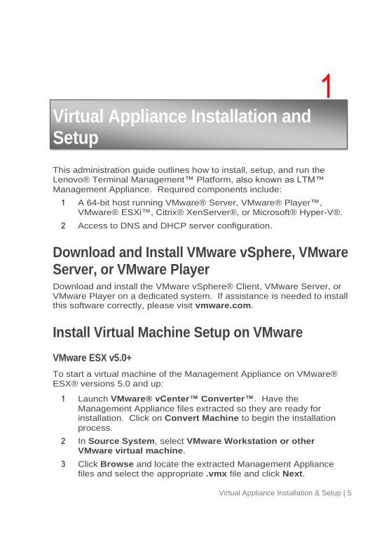
This administration guide outlines how to install, setup, and run the Lenovo® Terminal Management™ Platform, also known as LTM™ Management Appliance. Required components include:
1 A 64-bit host running VMware® Server, VMware® Player™, VMware® ESXi™, Citrix® XenServer®, or Microsoft® Hyper-V®.
2 Access to DNS and DHCP server configuration.
Download and Install VMware vSphere, VMware Server, or VMware Player Download and install the VMware vSphere® Client, VMware Server, or VMware Player on a dedicated system. If assistance is needed to install this software correctly, please visit vmware.com.
Install Virtual Machine Setup on VMware
VMware ESX v5.0+
To start a virtual machine of the Management Appliance on VMware® ESX® versions 5.0 and up:
1 Launch VMware® vCenter™ Converter™. Have the
Management Appliance files extracted so they are ready for installation. Click on Convert Machine to begin the installation
process.
2 In Source System, select VMware Workstation or other VMware virtual machine.
3 Click Browse and locate the extracted Management Appliance files and select the appropriate .vmx file and click Next.
6 | Virtual Appliance Installation & Setup
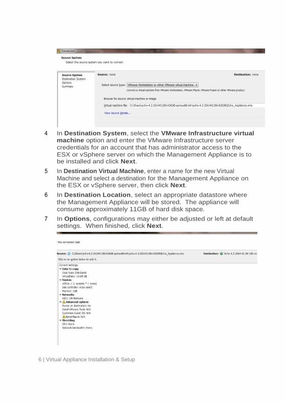
4 In Destination System, select the VMware Infrastructure virtual machine option and enter the VMware Infrastructure server
credentials for an account that has administrator access to the ESX or vSphere server on which the Management Appliance is to be installed and click Next.
5 In Destination Virtual Machine, enter a name for the new Virtual
Machine and select a destination for the Management Appliance on the ESX or vSphere server, then click Next.
6 In Destination Location, select an appropriate datastore where
the Management Appliance will be stored. The appliance will consume approximately 11GB of hard disk space.
7 In Options, configurations may either be adjusted or left at default settings. When finished, click Next.
Virtual Appliance Installation & Setup | 7
8 In Summary, verify that all the settings are correct and click Finish.
NOTE: Make sure that this is a newly downloaded appliance and not one that has been opened and run within VMware Player, VMware Server, or VMware® Workstation™.
VMware Server 2.0
To set up the virtual machine on VMware Server version 2.0:
1 Open the VMware Infrastructure Access Page.
2 From the toolbar, select Virtual Machine, then Add Virtual Machine to Inventory.
3 Expand the Inventory node to navigate to the appliance folder and double-click the appropriate .vmx file, then click OK.
4 On the VMware Infrastructure Web Access page, under the Inventory panel, select the newly-added virtual machine.
5 Depending on the amount of memory available on the host system, the allocated Memory may need to be reduced to a lower value. A minimum of 1024MB is required.
6 Power on the virtual machine.
VMware Server 1.0.x
To set up the virtual machine on VMware Server versions 1.0.0 through 1.0.8:
1 Select Open Existing Virtual Machine.
2 Select File, then Open and navigate to the correct .vmx file. This is added to the Inventory column.
3 Select the Adjust the Allocated Memory or Edit virtual machine settings options to adjust the amount of memory given to the
virtual appliance. This is dependent on the version of VMware Server that is being used.
4 After selecting the appliance settings, click Power On next to the
green triangle.

8 | Virtual Appliance Installation & Setup
Installing without VMware vCenter Converter
To start a virtual machine without the use of vCenter Converter:
1 Extract the Management Appliance files. Open the VMware Infrastructure Client and connect to the ESX or vSphere server.
2 Browse the datastore where the Management Appliance will be hosted in. Once in the Datastore Browser, select the option to Upload Folder.
3 Browse to the location of the extracted Management Appliance folder and select it for upload. When the Management Appliance has finished uploading, return to the VMware Infrastructure landing page.
4 Create a new Virtual Machine and select the hosting server that will run the Management Appliance.
5 At the Configuration screen, select the Custom option to allow for a customized setup process and click Next. In Name and Location, enter a name for the new Virtual Machine and select a
destination for the Management Appliance on the ESX or vSphere server, then click Next.
6 In Storage, select the datastore where the Management Appliance
will be stored. This should be the same datastore that was chosen in Step 2. For the Virtual Machine Version, select the version
best suited for the server.
7 In the Guest Operating System screen, select the OS type that
will be used. In most cases, the Guest OS for the Management Appliance will be Linux, with the Ubuntu Linux (64-bit) version.
8 For the CPU, Memory, and Network screens, the default options
will be acceptable in most cases. However, these can all be adjusted based on what is desired or specified. In SCSI Controller, select the LSI Logic Parallel option.
Virtual Appliance Installation & Setup | 9
9 In the Select a Disk screen, use the “Use an existing virtual disk” option. Choosing this option will create a new Select Existing Disk screen. From there, locate the folder that as uploaded from
the Datastore Browser in Step 2.
10 In Advanced Options, select a virtual device node and make
other adjustments. In most cases, these options can be left to their default settings.
11 Review all settings in the Ready to Complete screen before
finalizing the virtual machine. If everything looks acceptable, click Finish. The appliance can now be booted up to complete the
installation process.
VMware Player
To start a virtual machine on VMware Player:
1 Launch VMware Player and click Open.
2 Open the correct .vmx file located in the appropriate folder.
3 The virtual appliance will immediately begin booting.
Installing on XenServer® If the .xva file for the Management Appliance is available, follow these steps to
set up on XenServer®:
1 Open the XenCenter® Client.
2 The server should already be listed from the initial installation of XenCenter. Select the desired server from the inventory on the left hand side.
3 In XenCenter, access File, then Import and browse to the location of the XVA file. Click Next.
4 Select the server where the Management Appliance will be placed on. Click Next.
5 Select which storage repository to use from the list and click Import.
6 Choose the desired networking option and click Next.
7 Click Finish to complete the process.
10 | Virtual Appliance Installation & Setup
Installing on a Hyper-V® Server If the .vhd file for the Management Appliance is available, follow these steps to
set up on Hyper-V® server:
1 Open the Hyper-V® Manager.
2 If necessary, right click on Hyper-V® Manager in the left hand column and select Connect to Server…, then click Ok.
3 Click on Action, then New, followed by Virtual Machine on the right hand side. Click Next.
4 Name the management server. Click on Browse and navigate to the location where the files will be stored. Click Next.
5 Designate the amount of RAM (1024MB minimum) that will be allocated to the Hyper-V® server. Click on Next.
6 Select the connection to use from the dropdown menu and click Next.
7 Click on Use an existing virtual hard disk and then click Browse. Navigate to the .vhd file and click Next.
8 Confirm that the information presented is accurate. Click Previous to make any adjustments, or Finish if everything is
correct.

Virtual Appliance Installation & Setup | 11
Password and Time Zone Configurations 1 Turn on the Virtual Machine.
2 After the boot up process is complete, the Setting Password page
is displayed.
3 Enter a password for the default bwadmin account. This password
is required to initially log in to management platform.
NOTE: There is no minimum character limit required when entering a new password and the password is case sensitive. It is recommended that the administrator create a password of at least six characters, using a combination of upper and lowercase alphanumeric characters.
4 Once a password has been entered, use the arrow keys to navigate to the OK button and press <Enter> to continue. A
prompt will appear, asking for the password to be entered a second time. Press the OK button again.
5 A list of locations is displayed in the Change Time Zone page.
Select the appropriate time zone and press <Enter>.
12 | Virtual Appliance Installation & Setup
Network Configuration After the password and time zone have been configured, the next step of the initial setup wizard is to determine the IP configuration.
1 Enter a static IP address for this instance of the management platform, and press OK.
2 On the next page will be a prompt to enter the subnet mask. Typically, this will be a class C subnet mask (255.255.255.0). Once the subnet mask has been filled in, press OK.
3 On the Configure Gateway page, enter the gateway IP address and press OK.
4 On the Configure DNS Nameservers page, enter the IP addresses of
the nameservers, using a space in between each address. This will allow the appliance to resolve domain names. Once the IP addresses have been entered, press OK.
5 In the Configure DNS Search Domains page, enter the DNS
search path for the domain. If there are multiple domains, separate the entries with a space. Once all domains have been entered, press OK.
6 After selecting OK, the network interface will restart and the Main Menu will display.
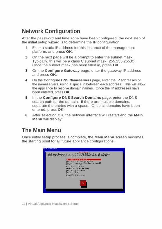
The Main Menu Once initial setup process is complete, the Main Menu screen becomes
the starting point for all future appliance configurations.
Virtual Appliance Installation & Setup | 13
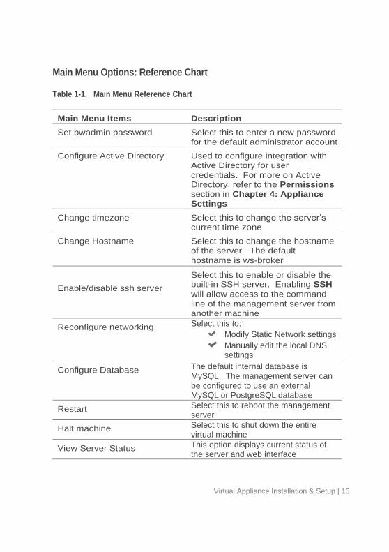
Main Menu Options: Reference Chart
Table 1-1. Main Menu Reference Chart
Main Menu Items Description
Set bwadmin password Select this to enter a new password for the default administrator account
Configure Active Directory Used to configure integration with Active Directory for user credentials. For more on Active Directory, refer to the Permissions section in Chapter 4: Appliance Settings
Change timezone Select this to change the server’s current time zone
Change Hostname Select this to change the hostname of the server. The default hostname is ws-broker
Enable/disable ssh server
Select this to enable or disable the built-in SSH server. Enabling SSH
will allow access to the command line of the management server from another machine
Reconfigure networking Select this to:
Modify Static Network settings
Manually edit the local DNS settings
Configure Database The default internal database is MySQL. The management server can be configured to use an external MySQL or PostgreSQL database
Restart Select this to reboot the management server
Halt machine Select this to shut down the entire virtual machine
View Server Status This option displays current status of the server and web interface

14 | Virtual Appliance Installation & Setup
Final Configuration Steps
DNS Configuration
By default, devices running LeTOS™ will attempt to resolve two types of DNS records:
A top-level, Host(A) Record named ws-broker.<local domain>
An SRV record named _mgr._tcp.<local domain>
It is recommended for simple deployments that the administrator use the first approach, and create a single DNS entry for ws-broker, assigned to
the static IP configured for the Management Appliance. For example:
ws-broker.myXyzConsulting.com
ws-broker.HiTechSolutions.net
ws-broker.development.org
In more complicated deployments where high availability is required it is recommended that an SRV record be used instead. Assigning a number of IP addresses for multiple instances of the Management Appliance allows for management reliability in failover scenarios.
Firewall Ports
Table 1-2. What Ports need to be Open for Functionality
Port Protocol Components Purpose
80 TCP Management Server
HTTP – Standard web port for the appliance Web UI
443 TCP Management Server
HTTPS – Secure (SSL) communication over http protocol
50000 TCP Management Server, Hosts, and Devices
Used by SOAP. This port needs to be open on ALL devices within the management environment
Virtual Appliance Installation & Setup | 15
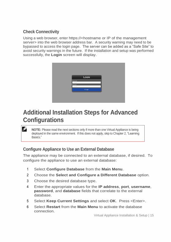
Check Connectivity
Using a web browser, enter https://<hostname or IP of the management server> into the web browser address bar. A security warning may need to be bypassed to access the login page. The server can be added as a “Safe Site” to avoid security warnings in the future. If the installation and setup was performed successfully, the Login screen will display.
Additional Installation Steps for Advanced Configurations
NOTE: Please read the next sections only if more than one Virtual Appliance is being deployed in the same environment. If this does not apply, skip to Chapter 2, “Learning Basics.”
Configure Appliance to Use an External Database
The appliance may be connected to an external database, if desired. To
configure the appliance to use an external database:
1 Select Configure Database from the Main Menu.
2 Choose the Select and Configure a Different Database option.
3 Choose the desired database type.
4 Enter the appropriate values for the IP address, port, username, password, and database fields that correlate to the external
database.
5 Select Keep Current Settings and select OK. Press <Enter>.
6 Select Restart from the Main Menu to activate the database
connection.
16 | Virtual Appliance Installation & Setup
Troubleshooting a Bad Connection Make sure that the appliance has network connectivity and that data packets
can flow to and from the appliance. To access different virtual terminals, press
<ALT> and the right arrow key. Once at the terminal prompt, the following will
be visible:
ws-broker login: _.
Log in using the username bwadmin and the password, which was set during
the initial configuration of the appliance. Test network connectivity by pinging
remote machines to ensure the appliance can see machines on the network.
Also ping the appliance from a thin client to make sure the device can see the
server.
If the server is not responding to any pings that are sent out or received, double-
check the network settings and make sure that port 50000 is open on the
network.
Learning Basics | 17
2 Learning Basics
Terminology The following terms are used throughout this document.
Device- This is the physical thin client to which the
monitor, keyboard and mouse are attached.
Session- This is a network connection between a thin
client and a host, with the display and USB components connected.
Cloning- This is a process of copying the profiles, settings,
or images from one device in order to make them available for application to other devices.
Accessing the Graphical Interface 1 Using a web browser, type the following URL into the address bar:
https://<hostname or IP of the appliance>, and press <Enter>.
2 Enter bwadmin in the Username field, and the password set up during installation in the Password field. Press <Enter>. If properly configured, and DNS settings are correct, the Administration Page will display.
The Administration Page The Administration Page is divided into two main sections. The left-
hand side displays the navigation bar with the various pages the administrator can navigate to. The central area of the page is dedicated to the inventory or configuration table depending on which tab is selected. The different administration pages are briefly described below. For further instruction on each page, see Chapter 3: Device Management.

18 | Learning Basics
Devices Page
The Devices page is where users may view an inventory of all devices
being managed by the management platform. Information such as the Name, IP Address, OS, and many other details of each device can be
viewed here.
Next to each device is a View Device button, a Logs button, and a
checkbox, used to select any number of devices at once. A group of devices can be selected by clicking on a device’s checkbox, followed by pressing <Shift> and clicking on the last device to be selected for that group. The View Device button lists all available details pertaining to
the device not displayed by default in the inventory, such as the Serial Number or UUID. The Logs button displays any logged events from the
selected device(s).
Connections Page
Devices have the ability to connect to remote services utilizing a number of connection types. The Connections page is where users can go to create,
manage, and edit any desktop connections that are available.
Profiles Page
A key function of the management platform is the creation and application of Profiles, in order to effectively manage the settings
applied to remote devices. A profile can contain a variety of options such as connections, settings, certificates, disk images, and software packages, which can then be applied to devices according to defined rules. The Profiles page is where the administrator can create, manage,
and edit these profiles.
Disk Images Page
A Disk Image is a file that can be included in order to combine different settings and profiles into one complete package. While creating Profiles and editing Device Settings provide ways to customize devices, uploading a Disk Image
allows the administrator to combine multiple profiles and settings, as well as an operating system, into a single resource. Utilizing disk images can simplify the management process.
Learning Basics | 19
Device Settings Page
Device Settings are the various settings, including display, sound,
keyboard, mouse, and password configurations, for a particular device. Administrators can use the management platform to clone these settings from one device, store them within the database, and then apply them to other devices.
NOTE: For more information on how to configure device settings, please refer to the OS guide. Details on how to alter these settings, install MUI packs, and select languages can be found there.
Certificates Page
Certificates can be added into the management platform and seen in the Certificates page. These certificates can then be pushed down to
devices through the main inventory page.
Software Page
Software packages allow administrators to incrementally patch existing devices
with updates or new versions of existing software. New packages may be released periodically for general use, or custom packages can be created as required by users. This table inventories the currently available packages that have been included by an administrator.
Tasks Page
The Tasks page can be used to monitor the progression status of Device Actions that were scheduled for deferred execution. Tasks that
are currently active can also have their schedules revised here.
Logs Page
The Logs page can be used to monitor and view activity on the
management platform, as well as changes made to devices themselves.
20 | Learning Basics
Searches The Search bar, located on the upper right-hand side of each inventory
table, allows users to easily search that table for specific information. A search scans all possible fields in each table, so it is possible to narrow the visible items based on specified criteria. Finding devices that share a common IP address, have the same model type, or use the same OS are a few of the many uses of this feature.
For example, if an administrator has to perform an update on all devices running LeTOS, typing “LeTOS” into the search field displays only those devices in the inventory table. The administrator can then perform updates with a more focused view of the devices being managed.
A new feature of the Management Appliance, Groups, supports usage
as a search term. Click on the group tag of a device, or enter “group:<groupname>”, and all devices that have been assigned to that group will display in the inventory table.
As information is entered into the Search field, the inventory table will
automatically update and display the items that match the search criteria.

Device Management | 21
3 Device Management
Action Bars At the top of each inventory table are a series of icons that allow administrators to perform various tasks. The available options differ from table to table.
Selection Tool
The first icon is the selection tool. This icon can be used to select all of the items listed in the inventory, or to ensure that none of them are selected. To use the selection tool, left click on the icon and click on Select All or Select None from the dropdown menu.
Add or Remove
The Add and Remove icons perform different tasks depending on which page is open. When used on the Devices tab, for instance, these icons
will allow the administrator to either add a new device to the managed devices list by entering an IP address, or to remove selected devices from the list. On the other pages, these icons are used to either create new entries (like profiles or disk images), or to remove entries.
22 | Device Management
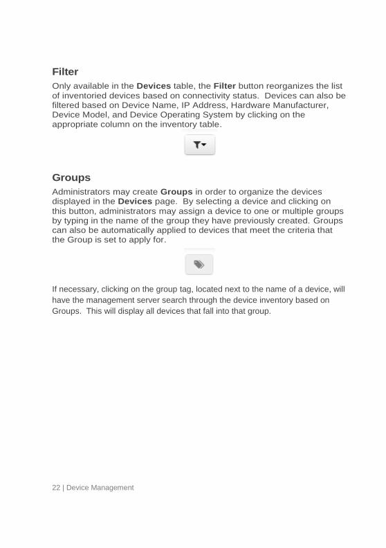
Filter
Only available in the Devices table, the Filter button reorganizes the list
of inventoried devices based on connectivity status. Devices can also be filtered based on Device Name, IP Address, Hardware Manufacturer, Device Model, and Device Operating System by clicking on the appropriate column on the inventory table.
Groups
Administrators may create Groups in order to organize the devices displayed in the Devices page. By selecting a device and clicking on
this button, administrators may assign a device to one or multiple groups by typing in the name of the group they have previously created. Groups can also be automatically applied to devices that meet the criteria that the Group is set to apply for.
If necessary, clicking on the group tag, located next to the name of a device, will
have the management server search through the device inventory based on
Groups. This will display all devices that fall into that group.
Device Management | 23
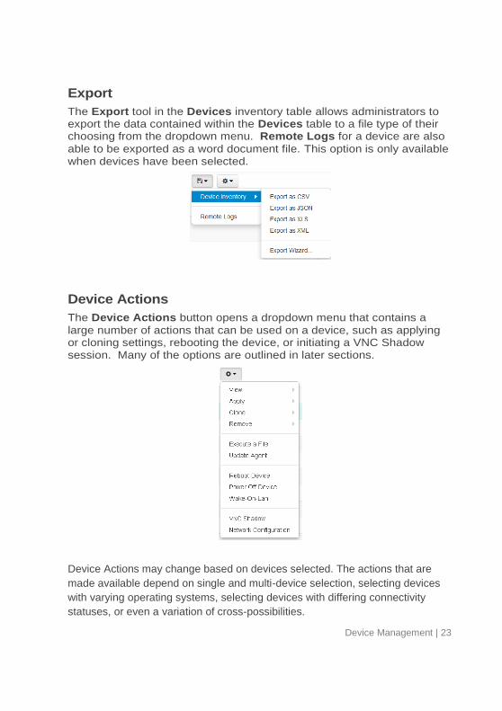
Export
The Export tool in the Devices inventory table allows administrators to export the data contained within the Devices table to a file type of their choosing from the dropdown menu. Remote Logs for a device are also
able to be exported as a word document file. This option is only available when devices have been selected.
Device Actions
The Device Actions button opens a dropdown menu that contains a
large number of actions that can be used on a device, such as applying or cloning settings, rebooting the device, or initiating a VNC Shadow session. Many of the options are outlined in later sections.
Device Actions may change based on devices selected. The actions that are
made available depend on single and multi-device selection, selecting devices
with varying operating systems, selecting devices with differing connectivity
statuses, or even a variation of cross-possibilities.

24 | Device Management
Cloning Overview The Management Appliance is able to clone the following types:
Connections- Devices have the ability to connect to
remote servers utilizing various types of protocols. The RDP® protocol is used to connect to Microsoft® Terminal Servers. The ICA® and XenAppView® protocols are used to establish connections to Citrix® servers. The VMware® Horizon View™ protocol allows a user to connect to a VMware Horizon View Server. Administrators may use the Management Appliance to clone these types of connections from one device, store them within their connections database, and then apply them to other devices.
Device Settings- Device settings are the permissions,
appearance, display, input, persistence, sound, printer, and time configurations for that particular device. Administrators may use the Management Appliance to clone these settings from one device, store them within the device settings database, and then apply them to other devices.
Profiles- Profiles are a way to combine multiple choices from both the Device Settings and Connections
configurations to create an arrangement of options tailored to the needs of the user. Administrators may use the Management Appliance to clone specific profiles to be applied to whichever devices require these combined settings.
Disk Images- The fourth cloning option is the ability to
clone the entire disk image of a device. A disk image includes everything that is stored on the DOM on that device, including the operating system itself. This does not include BIOS settings that have been saved elsewhere. Disk image clones are inventoried and managed by name within the disk images database, but are physically stored on an NFS share, CIFS, HTTP, HTTPS, or FTP server on the local area network.

Device Management | 25
Cloning Connections Administrators are able to clone individual connections from a thin client and save them in the Management Appliance database. Administrators can easily create a desktop connection on a device and then propagate it to all of their other devices via a profile. All connections can be cloned, and the most common are listed below:
RDP- One or more .rdp configuration files used for
connecting to Microsoft® Terminal Servers.
ICA- One or more .ica configuration files used for
connecting to Citrix servers.
XenAppView- Another option for accessing Citrix servers.
VMware- The connection settings and configurations for
the Horizon View client.
Firefox® or Internet Explorer®- The local web browser
and its starting URL.
AnyConnect® VPN- Establishes a VPN connection.
NX- Allows connectivity to a NoMachines session.
X11- The settings and configurations for an X11 server or
application.
How to Clone Connections
1 From the table of inventoried devices, select a device to clone connections from and then click on the Options button at the top
of the inventory table.
2 In the dropdown menu, go to Clone and click on Connections.
26 | Device Management
3 A Clone Connections dialogue box will open with a field entitled Connections.
4 Click on the Connections field to view a dropdown list of the
connections currently available for cloning from that device. Select one or several of the connections listed.
5 Click the checkmark in the top right corner of the Clone Connections dialogue box to create the clone.
6 The Connections tab will display the recently cloned connection
entries in the inventory table.
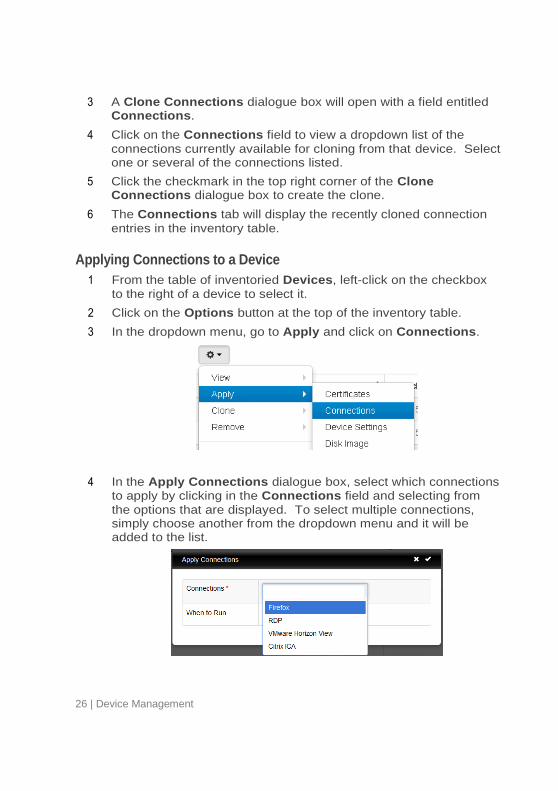
Applying Connections to a Device
1 From the table of inventoried Devices, left-click on the checkbox
to the right of a device to select it.
2 Click on the Options button at the top of the inventory table.
3 In the dropdown menu, go to Apply and click on Connections.
4 In the Apply Connections dialogue box, select which connections to apply by clicking in the Connections field and selecting from
the options that are displayed. To select multiple connections, simply choose another from the dropdown menu and it will be added to the list.
Device Management | 27
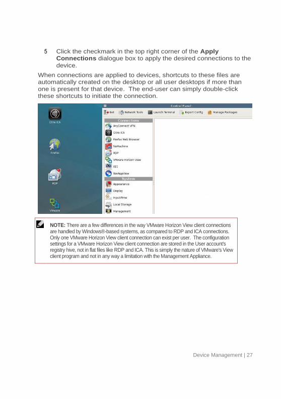
5 Click the checkmark in the top right corner of the Apply Connections dialogue box to apply the desired connections to the
device.
When connections are applied to devices, shortcuts to these files are automatically created on the desktop or all user desktops if more than one is present for that device. The end-user can simply double-click these shortcuts to initiate the connection.
NOTE: There are a few differences in the way VMware Horizon View client connections are handled by Windows®-based systems, as compared to RDP and ICA connections. Only one VMware Horizon View client connection can exist per user. The configuration settings for a VMware Horizon View client connection are stored in the User account's registry hive, not in flat files like RDP and ICA. This is simply the nature of VMware's View client program and not in any way a limitation with the Management Appliance.

28 | Device Management
Cloning Device Settings The following device settings to be cloned:
Permissions- The Agent Password that has been
assigned. If a password is set, Control Panel navigation will be restricted for non-password holders.
Appearance- The way in which icons are displayed,
sorted by either connection type or alphabetically by the connection’s assigned name.
Display- The screen resolution, color depth, and refresh
rate of the primary display device.
Input- The keyboard, mouse settings, and locale of the
device.
Sound- Settings for the master volume and mute control.
Persistence- The settings for persistence that have been
chosen for that device.
Time- Settings for the time zone.
USB- The USB permissions granted to the device.
Printers- Settings for a device’s attached printer. This
setting will not appear if the device does not have a printer plugged in with its properties established.
NOTE: The Persistence settings are only available to be cloned from devices running WES and do not apply to LeTOS units.
How to Clone Device Settings
1 From the Devices inventory table, select the device from which
settings will be cloned from.
2 Click the Options button at the top of the inventory panel. In the dropdown menu, go to Clone and click on Device Settings.
Device Management | 29
3 A Clone Device Settings dialogue box will open with three fields
to fill out:
Name- Enter a name for this clone. This name will be the name
that LTM refers to for these settings in the future.
Description- Enter a short description for this clone.
Device Settings- Select the type of settings that will be cloned.
Multiple options from the dropdown menu may be selected, and the selected modules will appear in a list within the Device Settings field. When cloning multiple device settings at once, these settings will be bundled together in the Device Settings
table afterwards.
4 Click the checkmark in the top right corner of the Clone Device Settings dialogue box to create the clone.
5 The Device Settings tab will display the recently cloned
connection entries in the inventory table.
Applying Settings to a Device
1 From the Devices inventory table, select the device or devices
desired.
2 Click the Options button at the top of the inventory panel. In the dropdown menu, go to Apply and click on Device Settings.
3 From the Apply Device Settings dialogue box, select the cloned
settings that will be applied from the dropdown menu.
4 Optionally, it is possible to reboot the device after the settings have been applied by selecting the checkbox under Reboot on success. If the new settings include network or
persistence/FBWF changes, then enabling this checkbox is recommended. Otherwise, this box can be left unchecked.
5 Click the checkmark in the top right corner of the Apply Device Settings dialogue box to apply the cloned settings to the device or
devices selected.
30 | Device Management
Profiles The profile feature allows administrators to assign connections and settings to one or more device. Profiles are useful for administrators that wish to effect updates on many devices at once. For instance, sometimes it becomes necessary to change the details of a connection that is used for multiple devices. If a profile has already been applied to those devices that contains the connection details, simply updating the connection details will automatically adjust the devices to use these new settings. The next two sections describe the necessary steps for creating and applying profiles.
How to Create a Profile
1 Open the Profiles tab to be taken to the profile inventory table.
2 Left-click on the Add Profile button above the inventory table.
3 The Add Profile dialogue box will open with seven fields to enter
information in:
Name- Enter a name for this profile.
Description- Enter a description about the profile.
Mode- Select between the following profile application options:
Default Profile – Apply to all devices on the server.
Select Devices – Manually select devices by name. This mode will override Default profiles. Once Select Devices is chosen, a Devices field will open where the administrator
can choose individual devices to apply this profile to by name.
Apply by terminal details – This will apply to all devices
that meet the specifications that are entered. When selected, the profile can specifically be applied by Device Name, IP Address, Range or Subnet, Device Model, or by OS.
Apply by group membership – Applies the profile to all
devices that have been assigned to one or more selected groups. When this option is chosen, a drop-down menu of all available groups is made available.

Device Management | 31
Disk Image- In the drop-down menu, if the administrator
adds an image to the profile, the Management Appliance will re-image the device every time it boots if it doesn’t already have the specific image listed here.
Connections- Assign connections to this profile by clicking in
the field and choosing which connections to include. It is also possible to select none at all.
Device Settings- Assign cloned settings to this profile by
clicking in the field and choosing which settings to include. It is also possible to select none at all.
Certificates- A certificate can be included to allow entry to
specific servers that have security restrictions. This may be required for certain sessions that would otherwise not allow access without a qualified certificate.
4 Once all of the information is correct, click on the checkmark on the top right hand corner of the Add Profile dialogue box.
5 The new profile entry is now listed in the Profiles inventory table.
Applying a Profile
Once a profile has been created as described in the section above, it will automatically apply the associated connections and settings the next time the devices included in the Mode field are rebooted. However, if to
make the changes take effect immediately, the profile may be manually applied by following the steps below:
32 | Device Management
1 From the table of inventoried Devices, select a device and then click on the Options button. From the dropdown menu, go to Apply and click on Profile.
2 From the dropdown under Profile, select which profile will be
applied.
3 Click the checkmark at the top right corner of the Apply Profile
dialogue box to confirm this change.
4 Connection shortcuts are automatically created on the device's desktop. The end-user can simply double-click these icons to initiate the connection.
Disk Image Cloning The Management Appliance allows administrators to perform full disk image cloning of devices, utilizing FTP, CIFS, HTTP, HTTPS or NFS protocols. Certain disk images are unable to support the disk image cloning process.
NOTE: To create a disk image clone from a WES® device, FBWF must be disabled. See the WES Administration Guide for instructions on how to do so.
How to Clone the Entire Disk Image
1 From the table of inventoried Devices, select a device and then click on the Options button. From the dropdown menu, go to Clone and click on Disk Image.
2 A dialogue box titled Clone Disk Image will open with four fields to
be filled out:
Name- Enter a name for this disk image.
Description- Enter a short description for this disk image.
Image Filename- Enter the filename desired for the new disk
image clone.
Storage Location- Select the storage location where the image will be saved from the dropdown menu. See Chapter 2: Appliance Settings for more information on setting up storage
locations.

Device Management | 33
3 Click the checkmark at the top right corner of the Clone Disk Image dialogue box to begin the cloning process. This process
may take a few moments, depending on the size of the device's flash disk and network traffic.
4 After completion, the newly cloned disk image can be seen in the inventory table of the Disk Images tab.
Applying a Disk Image to a Device
CAUTION: When applying disk images to devices, make sure to use the correct image for that particular model, otherwise the device may be rendered unbootable.
1 From the Devices inventory table, select a device or devices and then click the Options button. From the dropdown menu, go to Apply and then click on Disk Image.
2 In the Apply Disk Image dialogue box, select the desired disk
image from the dropdown menu. To have the device reboot and apply the disk image immediately, click in the checkbox next to Reboot on success.
3 Click the checkmark at the top right corner of the Apply Disk Image dialogue box to begin applying the disk image.
NOTE: Using the search function while performing disk image applications is advised. For example, by searching for “LeTOS” will cause only devices running LeTOS to be displayed. By utilizing the search function, administrators can avoid accidentally applying a disk image to a device of the wrong type or that is running a different OS.
4 Click the Submit button to begin the re-imaging process.
The disk image will either reboot to begin the updating process, or it will update
in the background so users do not have to be interrupted by the updating
process. The status of the update can be viewed at any time by checking the
Device Logs, either from the Logs inventory table or directly from the device
from the Devices inventory table. The re-imaging process may take a few
moments, depending on the size of the image and network traffic. During this
time, there is no agent to heartbeat into the server, and therefore the timestamp
in the Last Contact field of the View Device dialogue box will remain
unchanged. Once the re-image is complete, the device will be free to be
rebooted at the earliest convenience, or will automatically reboot if Reboot on
Success was selected. The agent will heartbeat into the server, which in turn
will update the Last Contact field. This update to the current time in the Last
Contact field means that the re-imaging process is complete.

34 | Device Management
Supplied Disk Images New OS images can be added to the Management Appliance inventory.
How to Add a Disk Image
1 Copy the image over to a CIFS shared directory, NFS, FTP, HTTP, or HTTPS server.
2 From the Disk Images tab, click on the Add button above the
inventory table.
3 A dialogue box titled Add Disk Image will open displaying various fields used to add the disk image. The Basic Information required
is:
Name- Enter a name for this disk image.
Description- A short description for this disk image can be
entered here.
Filename- The full filename of the disk image, as it is shown on
the server. This will need to include the file extension.
Checksum- Enter the hash of the disk image. This will be auto-
generated if the disk image is being pulled from an HTTP, HTTPS, or FTP server, but may take a few minutes, depending on network connectivity.
Product- Select the product from the dropdown menu which this
disk image can be applied to.
Storage Location- Choose the storage location where the disk
image has been saved.
Device Management | 35
Additionally, there are Legacy Options that older versions of disk images
may need:
MD5 SUM- Enter the md5sum of the disk image. This field is not
marked as required (*), however older versions of disk images will need this correctly filled.
4 Click the checkmark at the top right corner of the Add Disk Image
dialogue box to add this disk image to the inventory of disk images.
5 In the Disk Images tab, the inventory table will now contain the
recently added disk image. See the section titled, “Applying a Disk Image to a Device,” for instructions on how to apply the disk image to devices.
Software Packages
How to Add a Software Package
Software packages are used in order to apply specific updates or changes to
devices without having to update the entire image. Some examples for software
packages would be custom wallpaper images, updating software clients like
VMware Horizon View, Citrix, or RDP, potentially providing bug fixes, and more.
At this time, customer-created packages are not supported. In order to add a
software package to the Software inventory:
1 Click on the Software button to view the software inventory table.
2 Click the Add button at the top of the inventory table.
3 An Add Software dialogue box will open with several fields:
Name- Enter a name for this software package.
Description- A short description for this software package
can be entered here.
Filename- The full filename for the software package being
added. The file extension will need to be included.
Checksum- Enter the hash of the software package. This
will be auto-generated if the software is being pulled from an HTTP, HTTPS, or FTP server, but may take a few minutes, depending on network connectivity.
Product- Select the product from the dropdown menu which
this software package can be applied to.

36 | Device Management
Storage Location- Select the storage location where the
disk image has been saved.
4 Click the checkmark at the top right hand corner of the Add Software dialogue box to add the desired software package to the
software inventory.
Applying a Software Packages to a Device
1 From the Devices inventory table, select a device or multiple devices and then click the Options button.
2 Select Apply and then click on Software. This will open the Apply Software dialogue box.
NOTE: When applying software packages to devices, be sure to use the correct packages for that particular device and operating system. Packages that cannot be applied to the selected devices will not display in the dropdown menu.
3 From the Software dropdown list, select the package that will be
applied.
4 Click the checkmark at the top right hand corner of the Apply Software dialogue box to add the desired software package to the
selected devices.
Removing a Software Packages from a Device
1 From the Devices inventory table, select a device and then click the Options button.
2 Select Remove and then click on Software. This will open the Remove Software dialogue box.

Device Management | 37
3 In the Software field, select the desired software packages to be
removed from the device. Multiple packages may be selected, if needed.
4 Click the checkmark at the top right hand corner of the Remove Software dialogue box to remove the selected software packages
from the devices selected. The software package will be completely removed on the device’s next reboot.
Tasks Device activities can be deferred for later execution, and can be set to repeat at a schedule, if desired.
How to Create a New Task
1 From the Devices inventory table, select one or more devices that
will be receiving a new task.
2 Many device activities are eligible to be assigned as a scheduled task. This includes applying to devices and powering off, powering on, and rebooting devices.
3 When the activity has been selected, there will be the option to execute the action immediately, or to schedule it as a task for later. When creating a task, the following options are available:
Task Name- Enter a name for the task.
Date/Time- Select the date and time for the task to begin its initial
run.
Retries- The number of attempts the Management Appliance will
make to execute the task should networking or other issues occur while the task is being executed.

38 | Device Management
Frequency- The rate at which the task will be performed. A
custom frequency can also be entered.
4 Click the checkmark at the top right corner of the panel to assign the task. The task will remain in the Tasks inventory table, even
after it has completed its run.
5 If a task is still running, it can be edited within the Tasks inventory table by clicking on the Edit icon next to the task’s name. This will
allow changes to a task’s schedule or even halt the actions of a task, if necessary.
The Tasks inventory table allows administrators to search and sort for tasks based on their current status. Click on the Filter icon above the
table. A list of varying statuses will display in the menu. Selecting any of these statuses will display all of the tasks that fall under that status.
The status of a task can be viewed by the status icon, located next to the task’s name:
Grey Dot- The task is Ready, but has not yet run.
Spinning Circle- The task is currently Running.
Green Checkmark- This indicates the task is Finished if it was meant to be executed once, is Passing is the task is scheduled to repeat, or is OK if the task has completed all reoccurring
instances.
Yellow Exclamation Point- This task is currently Failing.
Red X-mark- The task has Failed.
Appliance Settings | 39
4 Appliance Settings
Server Settings At the top of the Administration Page is a link titled Settings. The Settings section handles additional features that can be used to
customize storage locations, groups, and maintenance and recovery options.
Licenses The Licenses tab can be used to apply licensing keys for the VDI
Blaster™ software. To add a license to the inventory:
1 From the Licenses inventory table, click the Add button at the top of the page. This will open the Add License menu.
2 In the field labeled License Key, enter in the VDI Blaster key
exactly as it appears.
3 Once the key has been correctly entered, click on the checkmark at the top right hand corner of the Add License menu to apply the
license to the Management Appliance.
Once a key has been applied, it will appear in the Licenses inventory
table. Each key allows a limited number of devices to be managed by the Management Appliance, and this number is listed in the Allowed Devices column. Keep in mind that these licenses are applied in a first-
come, first-served manner.
Products When a device with an unknown product type is added to the inventory, the
management platform will automatically add the product to the known products
list. Products may then be used to restrict actions to a subset of the inventory.
For instance, a product may be specified when creating a Software Package, to
ensure that the software can only be applied to devices running LeTOS.
40 | Appliance Settings
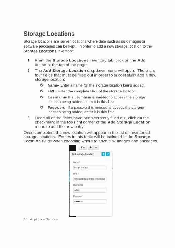
Storage Locations Storage locations are server locations where data such as disk images or
software packages can be kept. In order to add a new storage location to the
Storage Locations inventory:
1 From the Storage Locations inventory tab, click on the Add
button at the top of the page.
2 The Add Storage Location dropdown menu will open. There are
four fields that must be filled out in order to successfully add a new storage location:
Name- Enter a name for the storage location being added.
URL- Enter the complete URL of the storage location.
Username- If a username is needed to access the storage
location being added, enter it in this field.
Password- If a password is needed to access the storage
location being added, enter it in this field.
3 Once all of the fields have been correctly filled out, click on the checkmark in the top right corner of the Add Storage Location
menu to add the new entry.
Once completed, the new location will appear in the list of inventoried storage locations. Entries in this table will be included in the Storage Location fields when choosing where to save disk images and packages.

Appliance Settings | 41
Groups Administrators have the option of creating Groups within the
management console in order to help them organize their devices. Individual devices can belong to multiple groups. To create new groups:
1 From the Groups inventory table, click the Add button at the top of
the page.
2 The Add Group menu will open with two fields:
Name- Enter a name for the group being created.
Color- Click on the Color field to open a color wheel and
select the desired color.
Additionally, there are three Automatic Membership fields. These fields
are optional, but when used will automatically apply the Group to devices that feature one or more of the following:
IP Address/Subnet- This will allow the group to be
automatically applied to any devices that use this IP Address or falls under the subnet.
Model- This lets all of the specified models within the
Management Server become a member of the group. Only one model may be selected.
OS- The Operating System of the devices that will be a
member of this group. Only one OS may be selected.
3 When the group name and color have been entered, click on the checkmark at the upper right hand corner of the Add Group menu. The new group will appear in the Groups inventory.
42 | Appliance Settings
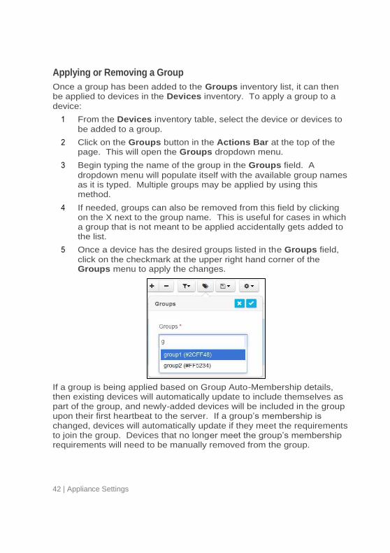
Applying or Removing a Group
Once a group has been added to the Groups inventory list, it can then be applied to devices in the Devices inventory. To apply a group to a
device:
1 From the Devices inventory table, select the device or devices to
be added to a group.
2 Click on the Groups button in the Actions Bar at the top of the page. This will open the Groups dropdown menu.
3 Begin typing the name of the group in the Groups field. A
dropdown menu will populate itself with the available group names as it is typed. Multiple groups may be applied by using this method.
4 If needed, groups can also be removed from this field by clicking on the X next to the group name. This is useful for cases in which a group that is not meant to be applied accidentally gets added to the list.
5 Once a device has the desired groups listed in the Groups field,
click on the checkmark at the upper right hand corner of the Groups menu to apply the changes.
If a group is being applied based on Group Auto-Membership details, then existing devices will automatically update to include themselves as part of the group, and newly-added devices will be included in the group upon their first heartbeat to the server. If a group’s membership is changed, devices will automatically update if they meet the requirements to join the group. Devices that no longer meet the group’s membership requirements will need to be manually removed from the group.
Appliance Settings | 43
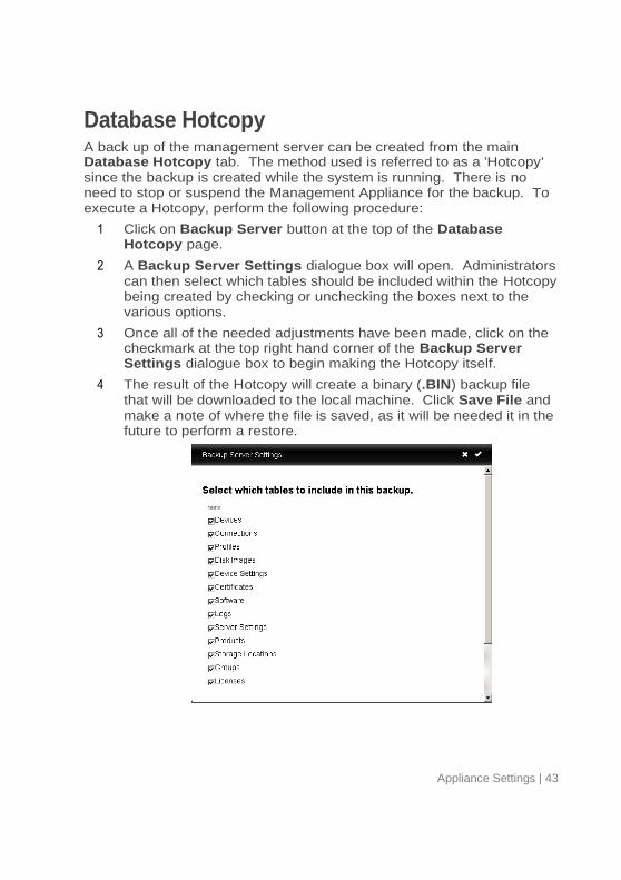
Database Hotcopy A back up of the management server can be created from the main Database Hotcopy tab. The method used is referred to as a 'Hotcopy'
since the backup is created while the system is running. There is no need to stop or suspend the Management Appliance for the backup. To execute a Hotcopy, perform the following procedure:
1 Click on Backup Server button at the top of the Database Hotcopy page.
2 A Backup Server Settings dialogue box will open. Administrators
can then select which tables should be included within the Hotcopy being created by checking or unchecking the boxes next to the various options.
3 Once all of the needed adjustments have been made, click on the checkmark at the top right hand corner of the Backup Server Settings dialogue box to begin making the Hotcopy itself.
4 The result of the Hotcopy will create a binary (.BIN) backup file that will be downloaded to the local machine. Click Save File and
make a note of where the file is saved, as it will be needed it in the future to perform a restore.
44 | Appliance Settings
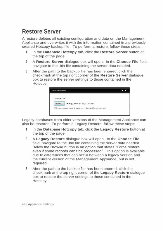
Restore Server A restore deletes all existing configuration and data on the Management Appliance and overwrites it with the information contained in a previously created Hotcopy backup file. To perform a restore, follow these steps:
1 In the Database Hotcopy tab, click the Restore Server button at
the top of the page.
2 A Restore Server dialogue box will open. In the Choose File field,
navigate to the .bin file containing the server data needed.
3 After the path to the backup file has been entered, click the checkmark at the top right corner of the Restore Server dialogue
box to restore the server settings to those contained in the Hotcopy.
Legacy databases from older versions of the Management Appliance can also be restored. To perform a Legacy Restore, follow these steps:
1 In the Database Hotcopy tab, click the Legacy Restore button at
the top of the page.
2 A Legacy Restore dialogue box will open. In the Choose File
field, navigate to the .bin file containing the server data needed. Below the Browse button is an option that states “Force restore even if some records can’t be processed”. This option is available due to differences that can occur between a legacy version and the current version of the Management Appliance, but is not required.
3 After the path to the backup file has been entered, click the checkmark at the top right corner of the Legacy Restore dialogue
box to restore the server settings to those contained in the Hotcopy.
Appliance Settings | 45
Permissions Permissions can be set for the accounts of active directory groups that will be using the Management Appliance. To select permissions for group accounts, the Management Appliance must first enable Active Directory support:
1 Access the Management Appliance Configuration menu from the Virtual Machine that is hosting the server. Select the Configure Active Directory option.
2 Select Enable Active Directory Support and choose the Yes
option. This will enable Active Directory support for the Management Appliance.
3 Enter all of the information required. This will include the Kerberos realm, DNS or AD domain names, the server name, and the IP address of Active Directory on the local network.
4 For the Edit AD Admin Groups option, enter a group name that
has Administrative privileges within Active Directory. This group will be to the Administrator Group within the management server and will be given full access to the Management Appliance. Once everything has been entered, select the Keep current settings
option. The Management Appliance will ask for Administrator credentials to proceed.
Once the Active Directory has been set up, the Permissions that each group will have can be set up from within the Management Appliance’s WebGUI:
1 Click on the Permissions button to access the Permissions
inventory table.
2 Create a new group by clicking on the Add button at the top of the
page.
3 The Groups dropdown menu will display all groups that were
included during the Active Directory configuration process. If a group is not displaying, click on the Refresh button to reload the
group inventory.
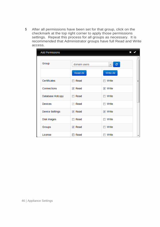
4 Once a group has been selected, all of the Read/Write access can be chosen for that group. Click on the Read All or Write All
buttons to allow privileges for all options. Write permissions are not available without Read permissions.
46 | Appliance Settings
5 After all permissions have been set for that group, click on the checkmark at the top right corner to apply those permissions settings. Repeat this process for all groups as necessary. It is recommended that Administrator groups have full Read and Write access.
Appliance Settings | 47
Appliance Upgrades The following is the recommended procedure for upgrading the Management Appliance to a newer version.
1 Backup- Back up the server’s current configuration and data prior
to performing an upgrade using the Hotcopy procedure. Refer to the Database Hotcopy section for details on this step.
2 Upgrade-
Shut down the appliance server (Select option 9, Halt Machine, from the Main Menu).
Download the latest management console appliance.
Extract the contents and point the VMware Server to the new file.
Restart the virtual appliance.
3 Restore- Once the upgrade is finished and the new appliance is
online, the management server will be ready for restoration. Refer to the Restore Server section for details on the restore process.
48 | Appliance Settings
5 Legal ©2014 Lenovo, Ltd. All rights reserved. Lenovo®, Lenovo Terminal Manager™, and LeTOS™ are trademarks or registered trademarks of Lenovo in the United States, other countries, or both. Devon IT and VDI Blaster are trademarks of Devon IT, Inc. All other company, brand, product, or trademark names are the property of their respective holders. VMware, VMware Server, VMware Player, VMware ESX, VMware ESXi, vSphere, vCenter Converter, and Horizon View are either trademarks or registered trademarks of VMware, Inc. in the United States and/or other jurisdictions. Citrix, ICA, XenAppView, and XenServer are registered trademarks of Citrix Systems, Inc. and/or one or more of its subsidiaries, and may be registered in the United States patent and Trademark Office and in other countries. Microsoft, Hyper-V, Windows, RDP, Windows Embedded, and Internet Explorer are registered trademarks of Microsoft Corporation in the United States and/or other countries. Firefox is a registered trademark of the Mozilla Foundation. AnyConnect is a registered trademark of Cisco Technology, Inc. and/or its affiliates in the United States and certain other countries.