lr1 - building 3d content section.pdf · 2010-05-11 · d joggle end e m6 shakeproof ... 2 grade...
TRANSCRIPT

OPAL
Cat. Nos.
A C D B E FB
EM 04/09
All information correct at date of issue.
A M6x16 setscrewB M6 washerC Side rail
D Joggle endE M6 shakeproof washerF M6 nut
COUPLING DETAIL:
FINISHES:Standard Finish:G Hot dip galvanised after manufacture to
BS EN ISO 1461.Additional Finishes - to order:S Stainless steel to BS EN 10088 -
2 grade 1·4404 (equivalent to 316L31).
Note: When bolting cut ends where the joggleend has been removed use coupler OC.Refer to Data Sheet LR6.01.
FASTENERSFour fastenersper joint. S
WIF
TS
CA
BL
E L
AD
DE
R
LR1.01PAGE 1 OF 1
W = width
STRAIGHTLENGTHS
For cable load capacitysee loading graphs.
OL W FINISH
ACTUALSIZE
DIMENSIONS & WEIGHTS
Weightkg
WidthW
100
150
225
300
450
600
Cat. Nos.
OL 100
OL 150
OL 225
OL 300
OL 450
OL 600
4.9
5.1
5.4
5.7
7.0
7.9
Type 4 rungs are usedas standard. For detailsrefer to Data SheetLR7.01.
DIMENSIONSAll dimensions given are inmillimetres (mm).
WEIGHTSAll weights given are inkilograms (kg) and are for hotdip galvanised G finish.
To obtain the appropriatecomponent weight in otherfinishes, multiply the givenweight by the following factors:
Stainless steel (S) x 0.94Powder coated (E) x 0.97
Finish: For ladders with G finish, fasteners arehigh tensile Grade 8.8. For ladders withS finish, fasteners are corrosionresistant stainless Grade A470.For ladders with E finish, the fastenersare Grade 8.8 hot dip galvanised. Analternative material for fasteners maybe required depending on theinstallation environment - contact ourSales Office for guidance.
STRAIGHT LENGTHTO STRAIGHT LENGTH BOLTING
3000
150 300RUNGPITCH
100
W - 3
W + 21
12
15
1.5THICK50
28
INTERNAL WIDTH
TYPE 4 RUNG
14
JOGGLE END DETAIL16.7
17
23 x 8 OBROUND SLOTS
33.3
END DETAIL33.3
23 x 8 OBROUND SLOTS
JOGGLE
JOGGLE
46

OPAL
Cat. Nos.
A C D B E FB
EM 04/09
All information correct at date of issue.
A M6x16 setscrewB M6 washerC Side rail
D Joggle endE M6 shakeproof washerF M6 nut
COUPLING DETAIL:
FINISHES:Standard Finish:G Hot dip galvanised after manufacture to
BS EN ISO 1461.Additional Finishes - to order:S Stainless steel to BS EN 10088 -
2 grade 1·4404 (equivalent to 316L31).
Note: When bolting cut ends where the joggleend has been removed use coupler OC.Refer to Data Sheet LR6.01.
FASTENERSFour fastenersper joint. S
WIF
TS
CA
BL
E L
AD
DE
R
LR1.02PAGE 1 OF 4
90°FLAT BENDS
W = width
OFB W 90 300 FINISHFor information on the use of X, Y, i and C dimensions,refer to Data Sheets LR7.03 and LR7.04.
X
160
i
160
C
WIDTH
Y300
JOGGLE
JOGGLE
Weightkg
No. ofRungs
4
4
4
4
4
4
1.6
1.7
2.0
2.2
2.9
3.4
WidthW
100
150
225
300
450
600
The standard inside radius for Opal bends is 300.
C
509
534
571
609
684
759
i
651
651
651
651
651
651
Y
509
534
571
609
684
759
X
509
534
571
609
684
759
16.733.3
1750
ENDDETAIL
THREE 23 x 8 OBROUND SLOTS
100
15
14JOGGLEENDDETAIL 16.7 33.3
46
THREE 23 x 8 OBROUND SLOTS
Cat. Nos.
OFB 100 90 300
OFB 150 90 300
OFB 225 90 300
OFB 300 90 300
OFB 450 90 300
OFB 600 90 300
DIMENSIONS & WEIGHTS
FLAT BEND TOSTRAIGHT LENGTH BOLTING
Finish: For bends with G finish, fasteners arehigh tensile Grade 8.8. For bends withS finish, fasteners are corrosionresistant stainless Grade A470.For bends with E finish, the fastenersare Grade 8.8 hot dip galvanised. Analternative material for fasteners maybe required depending on theinstallation environment - contact ourSales Office for guidance.DIMENSIONS
All dimensions given are in millimetres (mm).
WEIGHTSAll weights given are in kilograms (kg) and are for hot dipgalvanised G finish.
To obtain the appropriate component weight in otherfinishes, multiply the given weight by the following factors:
Stainless steel (S) x 0.94Powder coated (E) x 0.97
100
15
14JOGGLEENDDETAIL 16.7 33.3
46
THREE 23 x 8 OBROUND SLOTS
OPAL
Cat. Nos.
A C D B E FBA M6x16 setscrewB M6 washerC Side rail
D Joggle endE M6 shakeproof washerF M6 nut
COUPLING DETAIL:
FINISHES:Standard Finish:G Hot dip galvanised after manufacture to
BS EN ISO 1461.Additional Finishes - to order:S Stainless steel to BS EN 10088 -
2 grade 1·4404 (equivalent to 316L31).
Note: When bolting cut ends where the joggleend has been removed use coupler OC.Refer to Data Sheet LR6.01.
FASTENERSFour fastenersper joint.
EM 04/09
All information correct at date of issue.
SW
IFT
S C
AB
LE
LA
DD
ER
LR1.02PAGE 2 OF 4
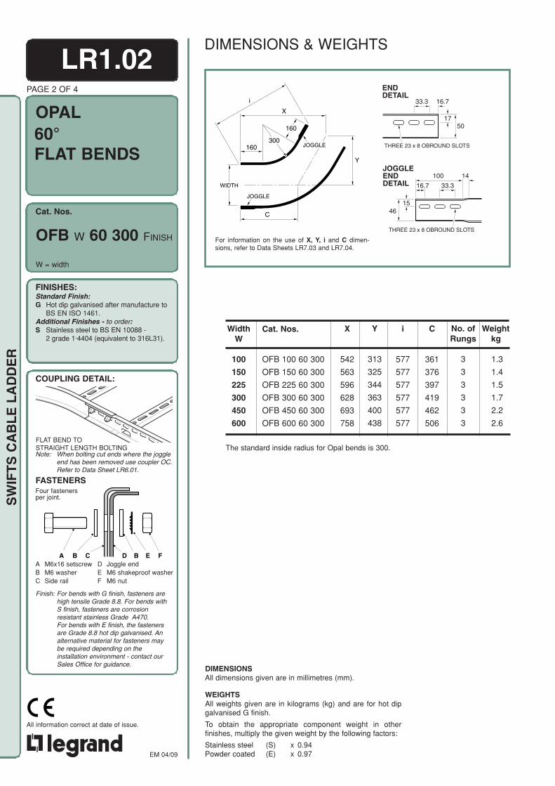
60°FLAT BENDS
W = width
OFB W 60 300 FINISH
DIMENSIONS & WEIGHTS
For information on the use of X, Y, i and C dimen-sions, refer to Data Sheets LR7.03 and LR7.04.
X
160
i
160300
C
WIDTH
Y
JOGGLE
JOGGLE
16.733.3
1750
ENDDETAIL
THREE 23 x 8 OBROUND SLOTS
The standard inside radius for Opal bends is 300.
Weightkg
No. ofRungs
3
3
3
3
3
3
1.3
1.4
1.5
1.7
2.2
2.6
WidthW
100
150
225
300
450
600
C
361
376
397
419
462
506
i
577
577
577
577
577
577
Y
313
325
344
363
400
438
X
542
563
596
628
693
758
Cat. Nos.
OFB 100 60 300
OFB 150 60 300
OFB 225 60 300
OFB 300 60 300
OFB 450 60 300
OFB 600 60 300
DIMENSIONSAll dimensions given are in millimetres (mm).
WEIGHTSAll weights given are in kilograms (kg) and are for hot dipgalvanised G finish.
To obtain the appropriate component weight in otherfinishes, multiply the given weight by the following factors:
Stainless steel (S) x 0.94Powder coated (E) x 0.97
FLAT BEND TOSTRAIGHT LENGTH BOLTING
Finish: For bends with G finish, fasteners arehigh tensile Grade 8.8. For bends withS finish, fasteners are corrosionresistant stainless Grade A470.For bends with E finish, the fastenersare Grade 8.8 hot dip galvanised. Analternative material for fasteners maybe required depending on theinstallation environment - contact ourSales Office for guidance.

OPAL
Cat. Nos.
A C D B E FB
EM 04/09
All information correct at date of issue.
A M6x16 setscrewB M6 washerC Side rail
D Joggle endE M6 shakeproof washerF M6 nut
COUPLING DETAIL:
FINISHES:Standard Finish:G Hot dip galvanised after manufacture to
BS EN ISO 1461.Additional Finishes - to order:S Stainless steel to BS EN 10088 -
2 grade 1·4404 (equivalent to 316L31).
Note: When bolting cut ends where the joggleend has been removed use coupler OC.Refer to Data Sheet LR6.01.
FASTENERSFour fastenersper joint. S
WIF
TS
CA
BL
E L
AD
DE
R
W = width
LR1.02PAGE 3 OF 4
45°FLAT BENDS
OFB W 45 300 FINISHFor information on the use of X, Y, i and C dimensions,refer to Data Sheets LR7.03 and LR7.04.
X
160
i
160300
C
WIDTH
Y
JOGGLE
JOGGLE
16.733.3
1750
ENDDETAIL
THREE 23 x 8 OBROUND SLOTS
Weightkg
No. ofRungs
3
3
3
3
3
3
WidthW
100
150
225
300
450
600
X
520
537
564
590
643
696
i
525
525
525
525
525
525
Y
215
223
234
244
266
288
C
304
315
330
346
377
408
The standard inside radius for Opal bends is 300.
1.1
1.2
1.3
1.5
2.0
2.3
100
15
14JOGGLEENDDETAIL 16.7 33.3
46
THREE 23 x 8 OBROUND SLOTS
Cat. Nos.
OFB 100 45 300
OFB 150 45 300
OFB 225 45 300
OFB 300 45 300
OFB 450 45 300
OFB 600 45 300
DIMENSIONS & WEIGHTS
FLAT BEND TOSTRAIGHT LENGTH BOLTING
Finish: For bends with G finish, fasteners arehigh tensile Grade 8.8. For bends withS finish, fasteners are corrosionresistant stainless Grade A470.For bends with E finish, the fastenersare Grade 8.8 hot dip galvanised. Analternative material for fasteners maybe required depending on the installationenvironment - contact our Sales Officefor guidance.DIMENSIONS
All dimensions given are in millimetres (mm).
WEIGHTSAll weights given are in kilograms (kg) and are for hot dipgalvanised G finish.
To obtain the appropriate component weight in other finish-es, multiply the given weight by the following factors:
Stainless steel (S) x 0.94Powder coated (E) x 0.97
OPAL
Cat. Nos.
A C D B E FBA M6x16 setscrewB M6 washerC Side rail
D Joggle endE M6 shakeproof washerF M6 nut
COUPLING DETAIL:
FINISHES:Standard Finish:G Hot dip galvanised after manufacture to
BS EN ISO 1461.Additional Finishes - to order:S Stainless steel to BS EN 10088 -
2 grade 1·4404 (equivalent to 316L31).
Note: When bolting cut ends where the joggleend has been removed use coupler OC.Refer to Data Sheet LR6.01.
FASTENERSFour fastenersper joint.
EM 04/09
All information correct at date of issue.
SW
IFT
S C
AB
LE
LA
DD
ER
LR1.02PAGE 4 OF 4
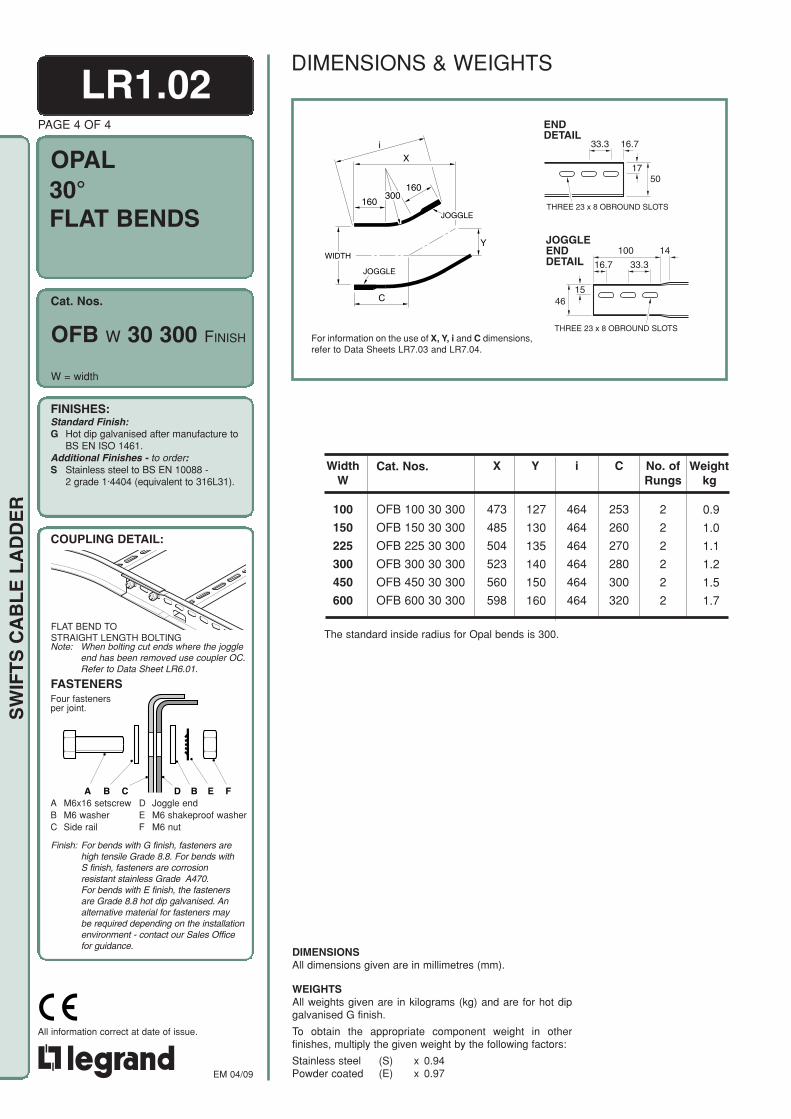
30°FLAT BENDS
OFB W 30 300 FINISH
W = width
DIMENSIONS & WEIGHTS
For information on the use of X, Y, i and C dimensions,refer to Data Sheets LR7.03 and LR7.04.
X
160
i
160300
C
WIDTH
Y
JOGGLE
JOGGLE
16.733.3
1750
ENDDETAIL
THREE 23 x 8 OBROUND SLOTS
Weightkg
No. ofRungs
2
2
2
2
2
2
0.9
1.0
1.1
1.2
1.5
1.7
WidthW
100
150
225
300
450
600
C
253
260
270
280
300
320
i
464
464
464
464
464
464
X
473
485
504
523
560
598
127
130
135
140
150
160
Y
The standard inside radius for Opal bends is 300.
100
15
14JOGGLEENDDETAIL 16.7 33.3
46
THREE 23 x 8 OBROUND SLOTS
Cat. Nos.
OFB 100 30 300
OFB 150 30 300
OFB 225 30 300
OFB 300 30 300
OFB 450 30 300
OFB 600 30 300
DIMENSIONSAll dimensions given are in millimetres (mm).
WEIGHTSAll weights given are in kilograms (kg) and are for hot dipgalvanised G finish.
To obtain the appropriate component weight in otherfinishes, multiply the given weight by the following factors:
Stainless steel (S) x 0.94Powder coated (E) x 0.97
FLAT BEND TOSTRAIGHT LENGTH BOLTING
Finish: For bends with G finish, fasteners arehigh tensile Grade 8.8. For bends withS finish, fasteners are corrosionresistant stainless Grade A470.For bends with E finish, the fastenersare Grade 8.8 hot dip galvanised. Analternative material for fasteners maybe required depending on the installationenvironment - contact our Sales Officefor guidance.

OPAL
Cat. Nos.
A C D B E FB
EM 04/09
All information correct at date of issue.
A M6x16 setscrewB M6 washerC Side rail
D Joggle endE M6 shakeproof washerF M6 nut
COUPLING DETAIL:
FINISHES:Standard Finish:G Hot dip galvanised after manufacture to
BS EN ISO 1461.Additional Finishes - to order:S Stainless steel to BS EN 10088 -
2 grade 1·4404 (equivalent to 316L31).
Note: When bolting cut ends where the joggleend has been removed use coupler OC.Refer to Data Sheet LR6.01.
FASTENERSFour fastenersper joint. S
WIF
TS
CA
BL
E L
AD
DE
R
LR1.03PAGE 1 OF 4
90° RISERSINSIDE &OUTSIDE
OIR W 90 300 FINISH
W = width
RISER TOSTRAIGHT LENGTH BOLTING
For information on the use of X, Y, i andC dimensions, refer to Data SheetsLR7.03 and LR7.04.
16.733.3
1750
ENDDETAIL
THREE 23 x 8 OBROUND SLOTS
Weightkg
No. ofRungs
4
4
4
4
4
4
1.4
1.5
1.6
1.8
2.3
2.6
WidthW
100
150
225
300
450
600
Y
450
450
450
450
450
450
i
605
605
605
605
605
605
Cat. Nos. given in the table are forinside risers. For outside riserssubstitute OOR for OIR.
The standard inside radius forOpal risers is 300.
C
450
450
450
450
450
450
X
450
450
450
450
450
450
100
15
14JOGGLEENDDETAIL 16.7 33.3
46
THREE 23 x 8 OBROUND SLOTS
X,C
i
Y
300
JOGGLE
OOR W 90 300 FINISH
Cat. Nos.
OIR 100 90 300
OIR 150 90 300
OIR 225 90 300
OIR 300 90 300
OIR 450 90 300
OIR 600 90 300
DIMENSIONS & WEIGHTS
Finish: For risers with G finish, fasteners arehigh tensile Grade 8.8. For risers withSS finish, fasteners are corrosionresistant stainless Grade A470.For risers with E finish, the fastenersare Grade 8.8 hot dip galvanised. Analternative material for fasteners maybe required depending on the installationenvironment - contact our Sales Officefor guidance.
DIMENSIONSAll dimensions given are in millimetres (mm).
WEIGHTSAll weights given are in kilograms (kg) and are for hot dipgalvanised G finish.
To obtain the appropriate component weight in other finish-es, multiply the given weight by the following factors:
Stainless steel (S) x 0.94Powder coated (E) x 0.97

OPAL
Cat. Nos.
A C D B E FBA M6x16 setscrewB M6 washerC Side rail
D Joggle endE M6 shakeproof washerF M6 nut
COUPLING DETAIL:
FINISHES:Standard Finish:G Hot dip galvanised after manufacture to
BS EN ISO 1461.Additional Finishes - to order:S Stainless steel to BS EN 10088 -
2 grade 1·4404 (equivalent to 316L31).
Note: When bolting cut ends where the joggleend has been removed use coupler OC.Refer to Data Sheet LR6.01.
FASTENERSFour fastenersper joint.
EM 04/09
All information correct at date of issue.
SW
IFT
S C
AB
LE
LA
DD
ER
LR1.03PAGE 2 OF 4
RISER TOSTRAIGHT LENGTH BOLTING
W = width
60° RISERSINSIDE &OUTSIDE
For information on the use of X, Y, i and C dimensions,refer to Data Sheets LR7.03 and LR7.04.
16.733.3
1750
ENDDETAIL
THREE 23 x 8 OBROUND SLOTS
Weightkg
No. ofRungs
3
3
3
3
3
3
1.1
1.2
1.3
1.4
1.8
2.0
WidthW
100
150
225
300
450
600
Cat. Nos. given in the table are forinside risers. For outside riserssubstitute OOR for OIR.
C
313
313
313
313
313
313
i
520
520
520
520
520
520
Y
271
271
271
271
271
271
X
469
469
469
469
469
469
The standard inside radius forOpal risers is 300.
100
15
14JOGGLEENDDETAIL 16.7 33.3
46
THREE 23 x 8 OBROUND SLOTS
C
i
X
Y300
JOGGLE
OIR W 60 300 FINISH
OOR W 60 300 FINISH
Cat. Nos.
OIR 100 60 300
OIR 150 60 300
OIR 225 60 300
OIR 300 60 300
OIR 450 60 300
OIR 600 60 300
DIMENSIONS & WEIGHTS
DIMENSIONSAll dimensions given are in millimetres (mm).
WEIGHTSAll weights given are in kilograms (kg) and are for hot dipgalvanised G finish.
To obtain the appropriate component weight in otherfinishes, multiply the given weight by the following factors:
Stainless steel (S) x 0.94Powder coated (E) x 0.97
Finish: For risers with G finish, fasteners arehigh tensile Grade 8.8. For risers withS finish, fasteners are corrosionresistant stainless Grade A470.For risers with E finish, the fastenersare Grade 8.8 hot dip galvanised. Analternative material for fasteners maybe required depending on the installationenvironment - contact our Sales Officefor guidance.

OPAL
Cat. Nos.
A C D B E FB
EM 04/09
All information correct at date of issue.
A M6x16 setscrewB M6 washerC Side rail
D Joggle endE M6 shakeproof washerF M6 nut
COUPLING DETAIL:
FINISHES:Standard Finish:G Hot dip galvanised after manufacture to
BS EN ISO 1461.Additional Finishes - to order:S Stainless steel to BS EN 10088 -
2 grade 1·4404 (equivalent to 316L31).
Note: When bolting cut ends where the joggleend has been removed use coupler OC.Refer to Data Sheet LR6.01.
FASTENERSFour fastenersper joint. S
WIF
TS
CA
BL
E L
AD
DE
R
LR1.03PAGE 3 OF 4
45° RISERSINSIDE &OUTSIDE
W = width
Weightkg
No. ofRungs
2
2
2
2
2
2
0.9
1.0
1.0
1.1
1.4
1.6
WidthW
100
150
225
300
450
600
C
260
260
260
260
260
260
i
463
463
463
463
463
463
Y
183.5
183.5
183.5
183.5
183.5
183.5
X
443
443
443
443
443
443
The standard inside radius forOpal risers is 300.
Cat. Nos. given in the table are forinside risers. For outside riserssubstitute OOR for OIR.
For information on the use of X, Y, i and Cdimensions, refer to Data Sheets LR7.03 andLR7.04.
16.733.3
1750
ENDDETAIL
THREE 23 x 8 OBROUND SLOTS
100
15
14JOGGLEENDDETAIL 16.7 33.3
46
THREE 23 x 8 OBROUND SLOTS
i
Y
C
X
300
JOGGLE
OIR W 45 300 FINISH
OOR W 45 300 FINISH
Cat. Nos.
OIR 100 45 300
OIR 150 45 300
OIR 225 45 300
OIR 300 45 300
OIR 450 45 300
OIR 600 45 300
DIMENSIONS & WEIGHTS
RISER TOSTRAIGHT LENGTH BOLTING
Finish: For risers with G finish, fasteners arehigh tensile Grade 8.8. For risers withS finish, fasteners are corrosionresistant stainless Grade A470.For risers with E finish, the fastenersare Grade 8.8 hot dip galvanised. Analternative material for fasteners maybe required depending on theinstallation environment - contact ourSales Office for guidance.
DIMENSIONSAll dimensions given are in millimetres (mm).
WEIGHTSAll weights given are in kilograms (kg) and are for hot dipgalvanised G finish.
To obtain the appropriate component weight in other finish-es, multiply the given weight by the following factors:
Stainless steel (S) x 0.94Powder coated (E) x 0.97

OPAL
Cat. Nos.
A C D B E FBA M6x16 setscrewB M6 washerC Side rail
D Joggle endE M6 shakeproof washerF M6 nut
COUPLING DETAIL:
FINISHES:Standard Finish:G Hot dip galvanised after manufacture to
BS EN ISO 1461.Additional Finishes - to order:S Stainless steel to BS EN 10088 -
2 grade 1·4404 (equivalent to 316L31).
Note: When bolting cut ends where the joggleend has been removed use coupler OC.Refer to Data Sheet LR6.01.
FASTENERSFour fastenersper joint.
EM 04/09
All information correct at date of issue.
SW
IFT
S C
AB
LE
LA
DD
ER
PAGE 4 OF 4
30° RISERSINSIDE &OUTSIDE
W = width
LR1.03
Cat. Nos. given in the table are forinside risers. For outside risers substi-tute OOR for OIR.
The standard inside radius forOpal risers is 300.
Weightkg
No. ofRungs
2
2
2
2
2
2
0.8
0.8
0.9
0.9
1.2
1.4
WidthW
100
150
225
300
450
600
X
396
396
396
396
396
396
Y
106
106
106
106
106
106
i
398
398
398
398
398
398
C
212
212
212
212
212
212
For information on the use of X, Y, i and Cdimensions, refer to Data Sheets LR7.03 andLR7.04.
16.733.3
1750
ENDDETAIL
THREE 23 x 8 OBROUND SLOTS
100
15
14JOGGLEENDDETAIL 16.7 33.3
46
THREE 23 x 8 OBROUND SLOTS
C
X
Y
i
300
JOGGLE
OIR W 30 300 FINISH
OOR W 30 300 FINISH
Cat. Nos.
OIR 100 30 300
OIR 150 30 300
OIR 225 30 300
OIR 300 30 300
OIR 450 30 300
OIR 600 30 300
DIMENSIONS & WEIGHTS
RISER TOSTRAIGHT LENGTH BOLTING
DIMENSIONSAll dimensions given are in millimetres (mm).
WEIGHTSAll weights given are in kilograms (kg) and are for hot dipgalvanised G finish.
To obtain the appropriate component weight in other finish-es, multiply the given weight by the following factors:
Stainless steel (S) x 0.94Powder coated (E) x 0.97
Finish: For risers with G finish, fasteners arehigh tensile Grade 8.8. For risers withS finish, fasteners are corrosionresistant stainless Grade A470.For risers with E finish, the fastenersare Grade 8.8 hot dip galvanised. Analternative material for fasteners maybe required depending on the installationenvironment - contact our Sales Officefor guidance.

OPAL
Cat. Nos.
A C D B E FB
EM 04/09
All information correct at date of issue.
A M6x16 setscrewB M6 washerC Side rail
D Joggle endE M6 shakeproof washerF M6 nut
COUPLING DETAIL:
FINISHES:Standard Finish:G Hot dip galvanised after manufacture to
BS EN ISO 1461.Additional Finishes - to order:S Stainless steel to BS EN 10088 -
2 grade 1·4404 (equivalent to 316L31).
Note: When bolting cut ends where the joggleend has been removed use coupler OC.Refer to Data Sheet LR6.01.
FASTENERSFour fastenersper joint. S
WIF
TS
CA
BL
E L
AD
DE
R
LR1.04PAGE 1 OF 2
W= main run width,K= reduced run width
STRAIGHTREDUCERS
OSR W K FINISH
Weightkg
WidthW
150
300
600
WidthK
100
100150
100150225
100150225300
100150225300450
450
Cat. Nos.
OSR 150 100
OSR 225 100OSR 225 150
OSR 300 100OSR 300 150OSR 300 225
OSR 450 100OSR 450 150OSR 450 225OSR 450 300
OSR 600 100OSR 600 150OSR 600 225OSR 600 300OSR 600 450
Length
400
400400
450450400
450450450450
500500450450450
0.8
0.90.9
1.01.00.9
1.21.21.21.2
1.51.51.41.41.4
225
16.733.3
1750
ENDDETAIL
THREE 23 x 8 OBROUND SLOTS
100
15
14JOGGLEENDDETAIL 16.7 33.3
46
THREE 23 x 8 OBROUND SLOTS
DIMENSIONS & WEIGHTS
Finish: For reducers with G finish, fastenersare high tensile Grade 8.8. For reducerswith S finish, fasteners are corrosionresistant stainless Grade A470.For reducers with E finish, thefasteners are Grade 8.8 hot dipgalvanised. An alternative material forfasteners may be required dependingon the installation environment - contactour Sales Office for guidance.
DIMENSIONSAll dimensions given are in millimetres (mm).
WEIGHTSAll weights given are in kilograms (kg) and are for hot dipgalvanised G finish.
To obtain the appropriate component weight in other finish-es, multiply the given weight by the following factors:
Stainless steel (S) x 0.94Powder coated (E) x 0.97
REDUCER TOSTRAIGHT LENGTH BOLTING
WIDTHW
WIDTHK
200
LENGTH
JOGGLE
JOGGLE
20°

OPAL
Cat. Nos.
A C D B E FBA M6x16 setscrewB M6 washerC Side rail
D Joggle endE M6 shakeproof washerF M6 nut
COUPLING DETAIL:
FINISHES:Standard Finish:G Hot dip galvanised after manufacture to
BS EN ISO 1461.Additional Finishes - to order:S Stainless steel to BS EN 10088 -
2 grade 1·4404 (equivalent to 316L31).
Note: When bolting cut ends where the joggleend has been removed use coupler OC.Refer to Data Sheet LR6.01.
FASTENERSFour fastenersper joint.
EM 04/09
All information correct at date of issue.
SW
IFT
S C
AB
LE
LA
DD
ER
LR1.04PAGE 2 OF 2
OFFSETREDUCERSLH and RH
OLR W K FINISH
ORR W K FINISH
W= main run width,K= reduced run width
Weightkg
WidthW
150
300
600
WidthK
100
100150
100150225
100150225300
100150225300450
450
Cat. Nos.
OLR 150 100
OLR 225 100OLR 225 150
OLR 300 100OLR 300 150OLR 300 225
OLR 450 100OLR 450 150OLR 450 225OLR 450 300
OLR 600 100OLR 600 150OLR 600 225OLR 600 300OLR 600 450
Length
400
450450
450450450
550500500450
600550550500450
0.8
0.90.9
1.01.01.0
1.41.31.31.2
1.71.61.61.51.4
225
Cat. Nos. given in the table are for lefthand reducers. For right hand reducerssubstitute ORR for OLR.
16.733.3
1750
ENDDETAIL
THREE 23 x 8 OBROUND SLOTS
WIDTHK
WIDTHW
LEFT HAND REDUCER
LENGTH
200
JOGGLE
JOGGLE
100
15
14JOGGLEENDDETAIL 16.7 33.3
46
THREE 23 x 8 OBROUND SLOTS
DIMENSIONS & WEIGHTS
DIMENSIONSAll dimensions given are in millimetres (mm).
WEIGHTSAll weights given are in kilograms (kg) and are for hot dipgalvanised G finish.
To obtain the appropriate component weight in other finish-es, multiply the given weight by the following factors:
Stainless steel (S) x 0.94Powder coated (E) x 0.97
Finish: For reducers with G finish, fastenersare high tensile Grade 8.8. For reducerswith S finish, fasteners are corrosionresistant stainless Grade A470.For reducers with E finish, thefasteners are Grade 8.8 hot dipgalvanised. An alternative material forfasteners may be required dependingon the installation environment - contactour Sales Office for guidance.
REDUCER TOSTRAIGHT LENGTH BOLTING
WIDTHK
WIDTHW
RIGHT HAND REDUCER
LENGTH
200
JOGGLE
JOGGLE
20°

OPAL
Cat. Nos.
A C D B E FB
EM 04/09
All information correct at date of issue.
A M6x16 setscrewB M6 washerC Side rail
D Joggle endE M6 shakeproof washerF M6 nut
COUPLING DETAIL:
FINISHES:Standard Finish:G Hot dip galvanised after manufacture to
BS EN ISO 1461.Additional Finishes - to order:S Stainless steel to BS EN 10088 -
2 grade 1·4404 (equivalent to 316L31).
Note: When bolting cut ends where the joggleend has been removed use coupler OC.Refer to Data Sheet LR6.01.
FASTENERSFour fastenersper joint. S
WIF
TS
CA
BL
E L
AD
DE
R
OT W 300R FINISH
LR1.05PAGE 1 OF 1
EQUAL TEES
W = width
Weightkg
2.5
2.7
3.0
3.3
4.4
5.1
WidthW
100
150
225
300
450
600
Y
509
534
571
609
684
759
X
509
534
571
609
684
759
The standard inside radius for Opal equal tees is 300.
For information onthe use of X and Ydimensions, refer toData Sheet LR7.03.
Y160
160
300
WIDTHW
WIDTHW
X
JOGGLE
JOGGLE
JOGGLE
100
15
14JOGGLEENDDETAIL 16.7 33.3
46
THREE 23 x 8 OBROUND SLOTS
16.733.3
1750
ENDDETAIL
THREE 23 x 8 OBROUND SLOTS
DIMENSIONS & WEIGHTS
Cat. Nos.
OT 100 300R
OT 150 300R
OT 225 300R
OT 300 300R
OT 450 300R
OT 600 300R
Finish: For tees with G finish, fasteners arehigh tensile Grade 8.8. For tees withS finish, fasteners are corrosionresistant stainless Grade A470.For tees with E finish, the fastenersare Grade 8.8 hot dip galvanised. Analternative material for fasteners maybe required depending on the installationenvironment - contact our Sales Officefor guidance.
DIMENSIONSAll dimensions given are in millimetres (mm).
WEIGHTSAll weights given are in kilograms (kg) and are for hot dipgalvanised G finish.
To obtain the appropriate component weight in otherfinishes, multiply the given weight by the following factors:
Stainless steel (S) x 0.94Powder coated (E) x 0.97
EQUAL TEE TOSTRAIGHT LENGTH BOLTING

OPAL
Cat. Nos.
A C D B E FB
EM 04/09
All information correct at date of issue.
A M6x16 setscrewB M6 washerC Side rail
D Joggle endE M6 shakeproof washerF M6 nut
COUPLING DETAIL:
FINISHES:Standard Finish:G Hot dip galvanised after manufacture to
BS EN ISO 1461.Additional Finishes - to order:S Stainless steel to BS EN 10088 -
2 grade 1·4404 (equivalent to 316L31).
Note: When bolting cut ends where the joggleend has been removed use coupler OC.Refer to Data Sheet LR6.01.
FASTENERSFour fastenersper joint. S
WIF
TS
CA
BL
E L
AD
DE
R
LR1.06PAGE 1 OF 1
UNEQUALTEES
W = main run width, B = branch width
For information on the use of X and Y dimensions,refer to Data Sheet LR7.03.
16.733.3
1750
ENDDETAIL
THREE 23 x 8 OBROUND SLOTS
Weightkg
WidthB
509509509509509
534534534534534
571571571571571
609609609609609
684684684684684
759759759759759
150225300450600
100225300450600
100150300450600
100150225450600
100150225300600
100150225300450
WidthW
534571609684759
509571609684759
509534609684759
509534571684759
509534571609759
509534571609684
2.62.82.93.33.6
2.62.93.03.43.7
2.72.83.13.63.9
3.03.13.23.94.2
3.43.53.63.84.7
3.73.84.04.14.8
X Y
100
150
225
300
450
600
The standard inside radius for Opal unequal tees is 300.
100
15
14JOGGLEENDDETAIL 16.7 33.3
46
THREE 23 x 8 OBROUND SLOTS
DIMENSIONS & WEIGHTS
Cat. Nos.
OUT 100 150 300ROUT 100 225 300ROUT 100 300 300ROUT 100 450 300ROUT 100 600 300R
OUT 150 100 300ROUT 150 225 300ROUT 150 300 300ROUT 150 450 300ROUT 150 600 300R
OUT 225 100 300ROUT 225 150 300ROUT 225 300 300ROUT 225 450 300ROUT 225 600 300R
OUT 300 100 300ROUT 300 150 300ROUT 300 225 300ROUT 300 450 300ROUT 300 600 300R
OUT 450 100 300ROUT 450 150 300ROUT 450 225 300ROUT 450 300 300ROUT 450 600 300R
OUT 600 100 300ROUT 600 150 300ROUT 600 225 300ROUT 600 300 300ROUT 600 450 300R
OUT W B 300R FINISH
Finish: For tees with G finish, fasteners arehigh tensile Grade 8.8. For tees withS finish, fasteners are corrosionresistant stainless Grade A470.For tees with E finish, the fastenersare Grade 8.8 hot dip galvanised. Analternative material for fasteners maybe required depending on the installationenvironment - contact our Sales Officefor guidance.
DIMENSIONSAll dimensions given are inmillimetres (mm).
WEIGHTSAll weights given are in kilograms (kg) and are for hotdip galvanised G finish.
To obtain the appropriate component weight in other fin-ishes, multiply the given weight by the following factors:
Stainless steel (S) x 0.94Powder coated (E) x 0.97
UNEQUAL TEE TOSTRAIGHT LENGTH BOLTING
Y
160
160300
WIDTHW
WIDTHB
X
JOGGLE
JOGGLE
JOGGLE
OPAL
Cat. Nos.
A C D B E FB
EM 04/09
All information correct at date of issue.
A M6x16 setscrewB M6 washerC Side rail
D Joggle endE M6 shakeproof washerF M6 nut
COUPLING DETAIL:
FINISHES:Standard Finish:G Hot dip galvanised after manufacture to
BS EN ISO 1461.Additional Finishes - to order:S Stainless steel to BS EN 10088 -
2 grade 1·4404 (equivalent to 316L31).
Note: When bolting cut ends where the joggleend has been removed use coupler OC.Refer to Data Sheet LR6.01.
FASTENERSFour fastenersper joint. S
WIF
TS
CA
BL
E L
AD
DE
R
100
15
14JOGGLEENDDETAIL 16.7 33.3
46
THREE 23 x 8 OBROUND SLOTS
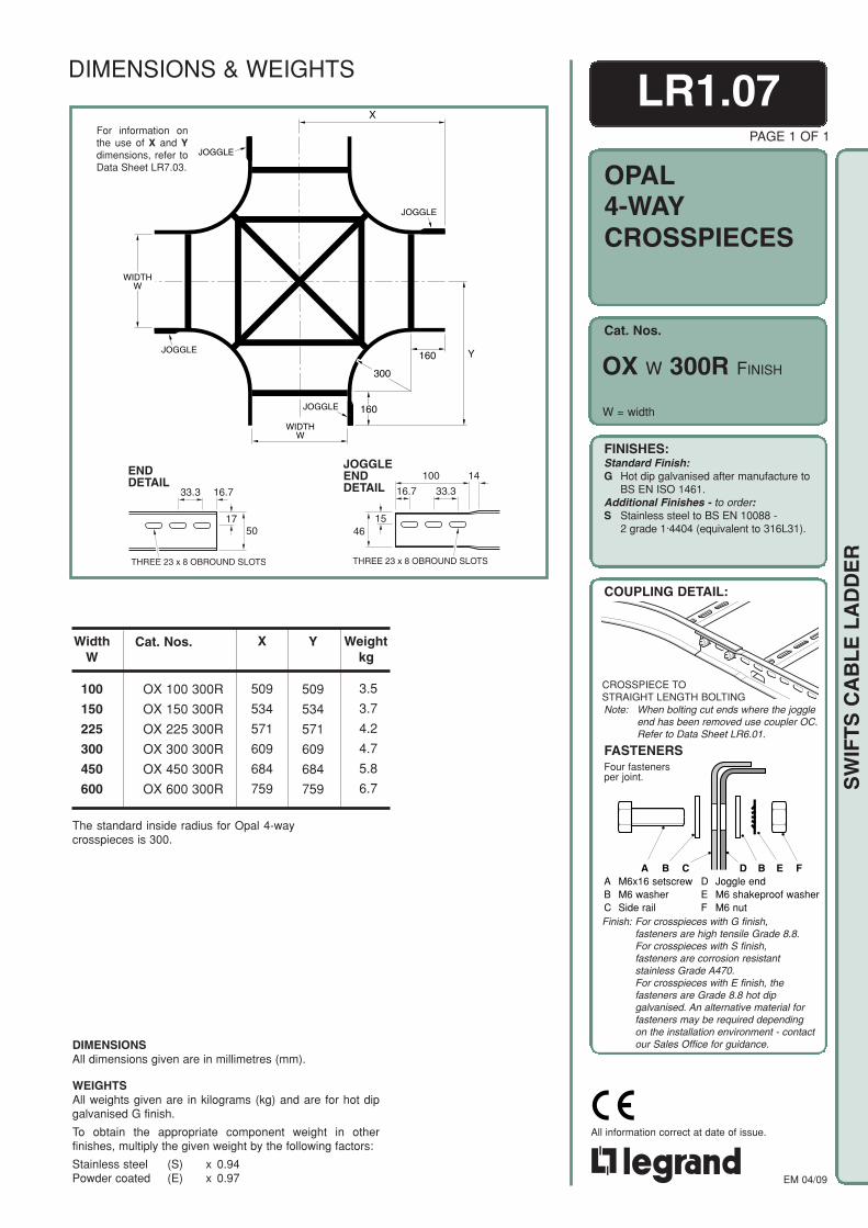
LR1.07
4-WAYCROSSPIECES
W = width
PAGE 1 OF 1
Weightkg
3.5
3.7
4.2
4.7
5.8
6.7
Y
509
534
571
609
684
759
WidthW
100
150
225
300
450
600
The standard inside radius for Opal 4-waycrosspieces is 300.
X
509
534
571
609
684
759
Y160
160
300
WIDTHW
WIDTHW
X
JOGGLE
JOGGLE
JOGGLE
JOGGLE
For information onthe use of X and Ydimensions, refer toData Sheet LR7.03.
16.733.3
1750
ENDDETAIL
THREE 23 x 8 OBROUND SLOTS
DIMENSIONS & WEIGHTS
OX W 300R FINISH
Cat. Nos.
OX 100 300R
OX 150 300R
OX 225 300R
OX 300 300R
OX 450 300R
OX 600 300R
DIMENSIONSAll dimensions given are in millimetres (mm).
WEIGHTSAll weights given are in kilograms (kg) and are for hot dipgalvanised G finish.
To obtain the appropriate component weight in otherfinishes, multiply the given weight by the following factors:
Stainless steel (S) x 0.94Powder coated (E) x 0.97
Finish: For crosspieces with G finish,fasteners are high tensile Grade 8.8.For crosspieces with S finish,fasteners are corrosion resistantstainless Grade A470.For crosspieces with E finish, thefasteners are Grade 8.8 hot dipgalvanised. An alternative material forfasteners may be required dependingon the installation environment - contactour Sales Office for guidance.
CROSSPIECE TOSTRAIGHT LENGTH BOLTING
Cat. Nos.
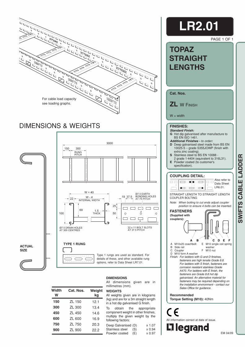
TOPAZ
FINISHES:Standard Finish:G Hot dip galvanised after manufacture to
BS EN ISO 1461.Additional Finishes - to order:D Deep galvanised steel made from BS EN
10025-5 – grade S355JOWP (finish withextra zinc coating).
S Stainless steel to BS EN 10088 -2 grade 1·4404 (equivalent to 316L31).
E Powder coated (to customer'sspecification).
COUPLING DETAIL:
(Supplied withcouplers):
FASTENERS
A B C D E FA M10x20 coachboltB Side railC CouplerD M10 form A washer
E M10 single coil springwasher
F M10 nut
EM 04/09
All information correct at date of issue.
SW
IFT
S C
AB
LE
LA
DD
ER
For cable load capacitysee loading graphs.
ACTUALSIZE
PAGE 1 OF 1
STRAIGHTLENGTHS
W = width
ZL W FINISH
DIMENSIONSAll dimensions given are inmillimetres (mm).
WEIGHTSAll weights given are in kilograms(kg) and are for a 3m straight lengthin a hot dip galvanised G finish.
To obtain the appropriatecomponent weight in other finishes,multiply the given weight by thefollowing factors:
Deep Galvanised (D) x 1.07Stainless steel (S) x 0.94Powder coated (E) x 0.97
Weightkg
WidthW
150
300
450
600
750
900
12.1
13.4
14.6
16.9
20.3
22.2
Cat. Nos.
ZL 150
ZL 300
ZL 450
ZL 600
ZL 750
ZL 900
DIMENSIONS & WEIGHTS
LR2.01
3000
150 300RUNGPITCH
37.519W - 4
W + 40
22
25
501.5
THICK69
100
INTERNAL WIDTH
Ø7.5 DRAIN HOLESAT 300 CENTRES
22 x 11 BOLT SLOTSAT 37.5 PITCH
Ø7.5 EARTHBONDING HOLESAT 75 PITCH
TYPE 1 RUNG
Type 1 rungs are used as standard. Fordetails of these, and other available rungoptions, refer to Data Sheet LR7.01.
STRAIGHT LENGTH TO STRAIGHT LENGTHCOUPLER BOLTING
Note: When bolting to cut ends adjust couplerposition to ensure 4 bolts can be inserted.
Also refer toData SheetLR6.01.
Finish: For ladders with G and D finishes,fasteners are high tensile Grade 8.8.For ladders with S finish, fasteners arecorrosion resistant stainless GradeA470. For ladders with E finish, thefasteners are Grade 8.8 hot dipgalvanised. An alternative material forfasteners may be required depending onthe installation environment - contact ourSales Office for guidance.
RecommendedTorque Setting (M10): 40Nm

Cat. Nos.
TOPAZ
FINISHES:Standard Finish:G Hot dip galvanised after manufacture to
BS EN ISO 1461.Additional Finishes - to order:D Deep galvanised steel made from BS EN
10025-5 – grade S355JOWP (finish withextra zinc coating).
S Stainless steel to BS EN 10088 -2 grade 1·4404 (equivalent to 316L31).
E Powder coated (to customer'sspecification).
COUPLING DETAIL:
(Supplied withcouplers):
FASTENERS
A B C D E FA M10x20 coachboltB Side railC CouplerD M10 form A washer
E M10 single coil springwasher
F M10 nut
EM 04/09
All information correct at date of issue.
SW
IFT
S C
AB
LE
LA
DD
ER
For information on the use of X, Y, iand C dimensions, refer to DataSheets LR7.03 and LR7.04.
END DETAIL
WEIGHTSAll weights given are in kilograms (kg) and are for hot dipgalvanised G finish.
To obtain the appropriate component weight in otherfinishes, multiply the given weight by the following factors:
Deep Galvanised (D) x 1.07Stainless steel (S) x 0.94Powder coated (E) x 0.97
DIMENSIONSAll dimensions given arein millimetres (mm).
90°FLAT BENDS
ZFB W 90 RAD FINISH
W = width
PAGE 1 OF 4
LR2.02
Weightkg
Cat. Nos.
ZFB 150 90 300ZFB 150 90 450ZFB 150 90 600ZFB 150 90 750ZFB 150 90 900
ZFB 300 90 300ZFB 300 90 450ZFB 300 90 600ZFB 300 90 750ZFB 300 90 900
ZFB 450 90 300ZFB 450 90 450ZFB 450 90 600ZFB 450 90 750ZFB 450 90 900
ZFB 600 90 300ZFB 600 90 450ZFB 600 90 600ZFB 600 90 750ZFB 600 90 900
ZFB 750 90 300ZFB 750 90 450ZFB 750 90 600ZFB 750 90 750ZFB 750 90 900
ZFB 900 90 300ZFB 900 90 450ZFB 900 90 600ZFB 900 90 750ZFB 900 90 900
No. ofRungs
33444
33445
34455
44555
45556
55566
Rad
300450600750900
300450600750900
300450600750900
300450600750900
300450600750900
300450600750900
WidthW
150
300
450
600
750
900
453603753903
1053
528678828978
1128
603753903
10531203
678828978
11281278
753903
105312031353
828978
112812781428
453603753903
1053
528678828978
1128
603753903
10531203
678828978
11281278
753903
105312031353
828978
112812781428
453603753903
1053
528678828978
1128
603753903
10531203
678828978
11281278
753903
105312031353
828978
112812781428
537750962
11741386
537750962
11741386
537750962
11741386
537750962
11741386
537750962
11741386
537750962
11741386
X Y i C
3.74.75.76.77.6
4.65.56.77.68.8
5.46.77.79.09.9
7.18.19.6
10.611.5
9.010.911.812.814.6
11.312.313.215.316.2
DIMENSIONS & WEIGHTS
10730 49 23 19 50
90 5020
5010
0
CHAMFER 7 x 45˚
4 SLOTS 37 X 13
2 HOLES 11 X 11
2 Ø 7.5 EARTHBONDING HOLES
5
Finish: For bends with G and D finishes,fasteners are high tensile Grade 8.8.For bends with S finish, fasteners arecorrosion resistant stainless Grade A470.For bends with E finish, the fasteners areGrade 8.8 hot dip galvanised. Analternative material for fasteners may berequired depending on the installationenvironment - contact our Sales Officefor guidance.
RecommendedTorque Setting (M10): 40Nm
FLAT BEND TOSTRAIGHT LENGTH COUPLER BOLTINGNote: When bolting to cut ends adjust coupler
position to ensure 2 bolts can be inserted.
X
80
i
80
C
WIDTH
Y
RADIUS

Cat. Nos.
TOPAZ
FINISHES:Standard Finish:G Hot dip galvanised after manufacture to
BS EN ISO 1461.Additional Finishes - to order:D Deep galvanised steel made from BS EN
10025-5 – grade S355JOWP (finish withextra zinc coating).
S Stainless steel to BS EN 10088 -2 grade 1·4404 (equivalent to 316L31).
E Powder coated (to customer'sspecification).
COUPLING DETAIL:
(Supplied withcouplers):
FASTENERS
A B C D E FA M10x20 coachboltB Side railC CouplerD M10 form A washer
E M10 single coil springwasher
F M10 nut
EM 04/09
All information correct at date of issue.
SW
IFT
S C
AB
LE
LA
DD
ER
END DETAIL
X
80
i
80RADIUS
C
WIDTH
Y
60°FLAT BENDS
ZFB W 60 RAD FINISH
W = width
For information on the use of X, Y, iand C dimensions, refer to DataSheets LR7.03 and LR7.04.
Weightkg
Cat. Nos.
ZFB 150 60 300ZFB 150 60 450ZFB 150 60 600ZFB 150 60 750ZFB 150 60 900
ZFB 300 60 300ZFB 300 60 450ZFB 300 60 600ZFB 300 60 750ZFB 300 60 900
ZFB 450 60 300ZFB 450 60 450ZFB 450 60 600ZFB 450 60 750ZFB 450 60 900
ZFB 600 60 300ZFB 600 60 450ZFB 600 60 600ZFB 600 60 750ZFB 600 60 900
ZFB 750 60 300ZFB 750 60 450ZFB 750 60 600ZFB 750 60 750ZFB 750 60 900
ZFB 900 60 300ZFB 900 60 450ZFB 900 60 600ZFB 900 60 750ZFB 900 60 900
Y
256331406481556
294369444519594
331406481556631
368443518593668
406481556631706
443518593668743
i
439589739889
1039
439589739889
1039
439589739889
1039
439589739889
1039
439589739889
1039
439589739889
1039
C
296382469555642
339426512599685
382469555642728
426512599685772
469555642729815
512598685772858
No. ofRungs
23333
33334
33344
33444
34444
44445
X
443573703833963
508638768898
1028
573703833963
1093
638768898
10281158
703833963
10931222
768898
102811571287
Rad
300450600750900
300450600750900
300450600750900
300450600750900
300450600750900
300450600750900
WidthW
150
300
450
600
750
900
2.83.64.24.85.5
3.64.24.95.56.4
4.34.95.66.67.2
5.35.97.17.88.4
6.68.28.89.5
10.1
8.69.39.9
10.512.3
LR2.02PAGE 2 OF 4
DIMENSIONSAll dimensions given arein millimetres (mm).
WEIGHTSAll weights given are in kilograms (kg) and are for hot dipgalvanised G finish.
To obtain the appropriate component weight in otherfinishes, multiply the given weight by the following factors:
Deep Galvanised (D) x 1.07Stainless steel (S) x 0.94Powder coated (E) x 0.97
DIMENSIONS & WEIGHTS
10730 49 23 19 50
90 5020
5010
0
CHAMFER 7 x 45˚
4 SLOTS 37 X 13
2 HOLES 11 X 11
2 Ø 7.5 EARTHBONDING HOLES
5
FLAT BEND TOSTRAIGHT LENGTH COUPLER BOLTINGNote: When bolting to cut ends adjust coupler
position to ensure 2 bolts can be inserted.
Finish: For bends with G and D finishes,fasteners are high tensile Grade 8.8.For bends with S finish, fasteners arecorrosion resistant stainless GradeA470. For bends with E finish, thefasteners are Grade 8.8 hot dipgalvanised. An alternative material forfasteners may be required dependingon the installation environment - contactour Sales Office for guidance.
RecommendedTorque Setting (M10): 40Nm

Cat. Nos.
TOPAZ
FINISHES:Standard Finish:G Hot dip galvanised after manufacture to
BS EN ISO 1461.Additional Finishes - to order:D Deep galvanised steel made from BS EN
10025-5 – grade S355JOWP (finish withextra zinc coating).
S Stainless steel to BS EN 10088 -2 grade 1·4404 (equivalent to 316L31).
E Powder coated (to customer'sspecification).
COUPLING DETAIL:
(Supplied withcouplers):
FASTENERS
A B C D E FA M10x20 coachboltB Side railC CouplerD M10 form A washer
E M10 single coil springwasher
F M10 nut
EM 04/09
All information correct at date of issue.
SW
IFT
S C
AB
LE
LA
DD
ER
X
80
i
80
RADIUS
C
WIDTH
Y
END DETAIL
For information on the use of X, Y, iand C dimensions, refer to DataSheets LR7.03 and LR7.04.
LR2.02PAGE 3 OF 4
W = width
WEIGHTSAll weights given are in kilograms (kg) and are for hot dipgalvanised G finish.
To obtain the appropriate component weight in otherfinishes, multiply the given weight by the following factors:
Deep Galvanised (D) x 1.07Stainless steel (S) x 0.94Powder coated (E) x 0.97
DIMENSIONSAll dimensions given arein millimetres (mm).
Weightkg
Cat. Nos.
ZFB 150 45 300ZFB 150 45 450ZFB 150 45 600ZFB 150 45 750ZFB 150 45 900
ZFB 300 45 300ZFB 300 45 450ZFB 300 45 600ZFB 300 45 750ZFB 300 45 900
ZFB 450 45 300ZFB 450 45 450ZFB 450 45 600ZFB 450 45 750ZFB 450 45 900
ZFB 600 45 300ZFB 600 45 450ZFB 600 45 600ZFB 600 45 750ZFB 600 45 900
ZFB 750 45 300ZFB 750 45 450ZFB 750 45 600ZFB 750 45 750ZFB 750 45 900
ZFB 900 45 300ZFB 900 45 450ZFB 900 45 600ZFB 900 45 750ZFB 900 45 900
166210254298342
188232276320364
210254298342385
232276320364407
254298342385429
276320364407451
235297359421483
266328390452514
297359421483545
328390452514576
359421483545607
390452514576638
No. ofRungs
22233
22333
23333
33333
33334
33344
400506612719825
453559665772878
506612719825931
559665772878984
612719825931
1037
665772878984
1090
Rad
300450600750900
300450600750900
300450600750900
300450600750900
300450600750900
300450600750900
WidthW
150
300
450
600
750
900
CiYX
377492607722837
377492607722837
377492607722837
377492607722837
377492607722837
377492607722837
2.42.93.44.04.4
2.93.44.14.65.0
3.44.24.75.25.6
4.75.15.66.16.6
5.96.46.97.48.8
6.77.27.79.39.7
45°FLAT BENDS
ZFB W 45 RAD FINISH
DIMENSIONS & WEIGHTS
10730 49 23 19 50
90 5020
5010
0
CHAMFER 7 x 45˚
4 SLOTS 37 X 13
2 HOLES 11 X 11
2 Ø 7.5 EARTHBONDING HOLES
5
Finish: For bends with G and D finishes,fasteners are high tensile Grade 8.8.For bends with S finish, fasteners arecorrosion resistant stainless GradeA470. For bends with E finish, thefasteners are Grade 8.8 hot dipgalvanised. An alternative material forfasteners may be required depending onthe installation environment - contact ourSales Office for guidance.
RecommendedTorque Setting (M10): 40Nm
FLAT BEND TOSTRAIGHT LENGTH COUPLER BOLTINGNote: When bolting to cut ends adjust coupler
position to ensure 2 bolts can be inserted.

Cat. Nos.
TOPAZ
FINISHES:Standard Finish:G Hot dip galvanised after manufacture to
BS EN ISO 1461.Additional Finishes - to order:D Deep galvanised steel made from BS EN
10025-5 – grade S355JOWP (finish withextra zinc coating).
S Stainless steel to BS EN 10088 -2 grade 1·4404 (equivalent to 316L31).
E Powder coated (to customer'sspecification).
COUPLING DETAIL:
(Supplied withcouplers):
FASTENERS
A B C D E FA M10x20 coachboltB Side railC CouplerD M10 form A washer
E M10 single coil springwasher
F M10 nut
EM 04/09
All information correct at date of issue.
SW
IFT
S C
AB
LE
LA
DD
ER
W = width
END DETAIL
X
80
i
80
RADIUS
C
WIDTHY
For information on the use of X, Y, iand C dimensions, refer to DataSheets LR7.03 and LR7.04.
WEIGHTSAll weights given are in kilograms (kg) and are for hot dipgalvanised G finish.
To obtain the appropriate component weight in otherfinishes, multiply the given weight by the following factors:
Deep Galvanised (D) x 1.07Stainless steel (S) x 0.94Powder coated (E) x 0.97
DIMENSIONSAll dimensions given arein millimetres (mm).
30°FLAT BENDS
2.02.32.73.03.3
2.42.73.13.43.7
2.83.13.53.84.5
3.43.84.15.05.3
4.34.65.96.26.5
4.86.36.66.97.2
Weightkg
Cat. Nos.
ZFB 150 30 300ZFB 150 30 450ZFB 150 30 600ZFB 150 30 750ZFB 150 30 900
ZFB 300 30 300ZFB 300 30 450ZFB 300 30 600ZFB 300 30 750ZFB 300 30 900
ZFB 450 30 300ZFB 450 30 450ZFB 450 30 600ZFB 450 30 750ZFB 450 30 900
ZFB 600 30 300ZFB 600 30 450ZFB 600 30 600ZFB 600 30 750ZFB 600 30 900
ZFB 750 30 300ZFB 750 30 450ZFB 750 30 600ZFB 750 30 750ZFB 750 30 900
ZFB 900 30 300ZFB 900 30 450ZFB 900 30 600ZFB 900 30 750ZFB 900 30 900
90110130150170
100120140160180
110130150170190
120140160180201
130150170190211
140160180201221
310387465543620
310387465543620
310387465543620
310387465543620
310387465543620
310387465543620
180220260301341
200240280321361
220260301341381
240281321361401
260301341381421
281321361401441
No. ofRungs
22222
22222
22223
22233
22333
23333
336411486561636
373448523598673
411486561636711
448523598673748
486561636711786
523598673748823
Rad
300450600750900
300450600750900
300450600750900
300450600750900
300450600750900
300450600750900
WidthW
150
300
450
600
750
900
CiYX
PAGE 4 OF 4
LR2.02
ZFB W 30 RAD FINISH
DIMENSIONS & WEIGHTS
10730 49 23 19 50
90 5020
5010
0
CHAMFER 7 x 45˚
4 SLOTS 37 X 13
2 HOLES 11 X 11
2 Ø 7.5 EARTHBONDING HOLES
5
Finish: For bends with G and D finishes,fasteners are high tensile Grade 8.8. Forbends with S finish, fasteners arecorrosion resistant stainless GradeA470. For bends with E finish, thefasteners are Grade 8.8 hot dipgalvanised. An alternative material forfasteners may be required depending onthe installation environment - contact ourSales Office for guidance.
RecommendedTorque Setting (M10): 40Nm
FLAT BEND TOSTRAIGHT LENGTH COUPLER BOLTINGNote: When bolting to cut ends adjust coupler
position to ensure 2 bolts can be inserted.
Cat. Nos.
TOPAZ
FINISHES:Standard Finish:G Hot dip galvanised after manufacture to
BS EN ISO 1461.Additional Finishes - to order:D Deep galvanised steel made from BS EN
10025-5 – grade S355JOWP (finish withextra zinc coating).
S Stainless steel to BS EN 10088 -2 grade 1·4404 (equivalent to 316L31).
E Powder coated (to customer'sspecification).
COUPLING DETAIL:
(Supplied withcouplers):
FASTENERS
A B C D E FA M10x20 coachboltB Side railC CouplerD M10 form A washer
E M10 single coil springwasher
F M10 nut
EM 04/09
All information correct at date of issue.
SW
IFT
S C
AB
LE
LA
DD
ER
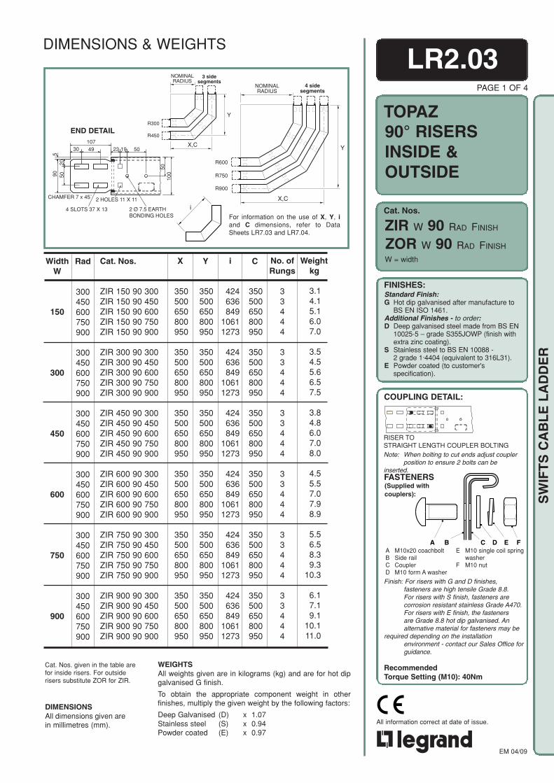
LR2.03PAGE 1 OF 4
90° RISERSINSIDE &OUTSIDE
ZIR W 90 RAD FINISH
ZOR W 90 RAD FINISH
W = width
NOMINALRADIUS
X,C
YR300
R450
3 sidesegments
END DETAIL
i
For information on the use of X, Y, iand C dimensions, refer to DataSheets LR7.03 and LR7.04.
WEIGHTSAll weights given are in kilograms (kg) and are for hot dipgalvanised G finish.
To obtain the appropriate component weight in otherfinishes, multiply the given weight by the following factors:
Deep Galvanised (D) x 1.07Stainless steel (S) x 0.94Powder coated (E) x 0.97
DIMENSIONSAll dimensions given arein millimetres (mm).
Cat. Nos. given in the table arefor inside risers. For outsiderisers substitute ZOR for ZIR.
350500650800950
350500650800950
350500650800950
350500650800950
350500650800950
350500650800950
Weightkg
350500650800950
350500650800950
350500650800950
350500650800950
350500650800950
350500650800950
424636849
10611273
424636849
10611273
424636849
10611273
424636849
10611273
424636849
10611273
424636849
10611273
350500650800950
350500650800950
350500650800950
350500650800950
350500650800950
350500650800950
No. ofRungs
33444
33444
33444
33444
33444
33444
3.14.15.16.07.0
3.54.55.66.57.5
3.84.86.07.08.0
4.55.57.07.98.9
5.56.58.39.3
10.3
6.17.19.1
10.111.0
Rad
300450600750900
300450600750900
300450600750900
300450600750900
300450600750900
300450600750900
WidthW
150
300
450
600
750
900
Cat. Nos.
ZIR 150 90 300ZIR 150 90 450ZIR 150 90 600ZIR 150 90 750ZIR 150 90 900
ZIR 300 90 300ZIR 300 90 450ZIR 300 90 600ZIR 300 90 750ZIR 300 90 900
ZIR 450 90 300ZIR 450 90 450ZIR 450 90 600ZIR 450 90 750ZIR 450 90 900
ZIR 600 90 300ZIR 600 90 450ZIR 600 90 600ZIR 600 90 750ZIR 600 90 900
ZIR 750 90 300ZIR 750 90 450ZIR 750 90 600ZIR 750 90 750ZIR 750 90 900
ZIR 900 90 300ZIR 900 90 450ZIR 900 90 600ZIR 900 90 750ZIR 900 90 900
CiYX
DIMENSIONS & WEIGHTS
10730 49 23 19 50
90 5020
5010
0
CHAMFER 7 x 45˚
4 SLOTS 37 X 13
2 HOLES 11 X 11
2 Ø 7.5 EARTHBONDING HOLES
5
RISER TOSTRAIGHT LENGTH COUPLER BOLTINGNote: When bolting to cut ends adjust coupler
position to ensure 2 bolts can beinserted.
Finish: For risers with G and D finishes,fasteners are high tensile Grade 8.8.For risers with S finish, fasteners arecorrosion resistant stainless Grade A470.For risers with E finish, the fastenersare Grade 8.8 hot dip galvanised. Analternative material for fasteners may be
required depending on the installationenvironment - contact our Sales Office forguidance.
RecommendedTorque Setting (M10): 40Nm
X,C
NOMINALRADIUS
R600
R750
R900
Y
4 sidesegments
Cat. Nos.
TOPAZ
FINISHES:Standard Finish:G Hot dip galvanised after manufacture to
BS EN ISO 1461.Additional Finishes - to order:D Deep galvanised steel made from BS EN
10025-5 – grade S355JOWP (finish withextra zinc coating).
S Stainless steel to BS EN 10088 -2 grade 1·4404 (equivalent to 316L31).
E Powder coated (to customer'sspecification).
COUPLING DETAIL:
(Supplied withcouplers):
FASTENERS
A B C D E FA M10x20 coachboltB Side railC CouplerD M10 form A washer
E M10 single coil springwasher
F M10 nut
EM 04/09
All information correct at date of issue.
SW
IFT
S C
AB
LE
LA
DD
ER
10730 49 23 19 50
90 5020
5010
0
CHAMFER 7 x 45˚
4 SLOTS 37 X 13
2 HOLES 11 X 11
2 Ø 7.5 EARTHBONDING HOLES
5
R300
R450
R900
NOMINALRADIUS
R600
R750
CX
Y
i
Z.2015-60RISER-i
END DETAIL
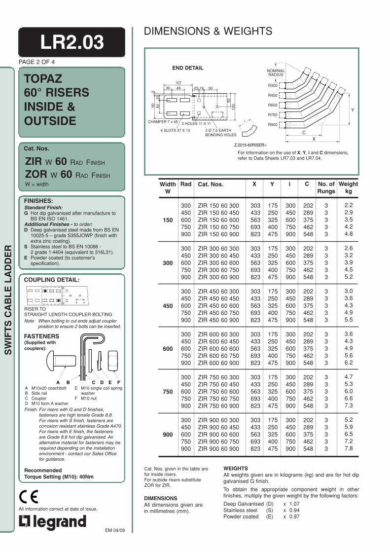
For information on the use of X, Y, i and C dimensions,refer to Data Sheets LR7.03 and LR7.04.
WEIGHTSAll weights given are in kilograms (kg) and are for hot dipgalvanised G finish.
To obtain the appropriate component weight in otherfinishes, multiply the given weight by the following factors:
Deep Galvanised (D) x 1.07Stainless steel (S) x 0.94Powder coated (E) x 0.97
DIMENSIONSAll dimensions given arein millimetres (mm).
Cat. Nos. given in the table arefor inside risers.For outside risers substituteZOR for ZIR.
LR2.03
60° RISERSINSIDE &OUTSIDE
PAGE 2 OF 4
Weightkg
175250325400475
175250325400475
175250325400475
175250325400475
175250325400475
175250325400475
300450600750900
300450600750900
300450600750900
300450600750900
300450600750900
300450600750900
202289375462548
202289375462548
202289375462548
202289375462548
202289375462548
202289375462548
No. ofRungs
33333
33333
33333
33333
33333
33333
303433563693823
303433563693823
303433563693823
303433563693823
303433563693823
303433563693823
Rad
300450600750900
300450600750900
300450600750900
300450600750900
300450600750900
300450600750900
WidthW
150
300
450
600
750
900
Cat. Nos.
ZIR 150 60 300ZIR 150 60 450ZIR 150 60 600ZIR 150 60 750ZIR 150 60 900
ZIR 300 60 300ZIR 300 60 450ZIR 300 60 600ZIR 300 60 750ZIR 300 60 900
ZIR 450 60 300ZIR 450 60 450ZIR 450 60 600ZIR 450 60 750ZIR 450 60 900
ZIR 600 60 300ZIR 600 60 450ZIR 600 60 600ZIR 600 60 750ZIR 600 60 900
ZIR 750 60 300ZIR 750 60 450ZIR 750 60 600ZIR 750 60 750ZIR 750 60 900
ZIR 900 60 300ZIR 900 60 450ZIR 900 60 600ZIR 900 60 750ZIR 900 60 900
2.22.93.54.24.8
2.63.23.94.55.2
3.03.64.34.95.5
3.64.34.95.66.2
4.75.36.06.67.3
5.25.96.57.27.8
CiYXW = width
ZOR W 60 RAD FINISH
ZIR W 60 RAD FINISH
DIMENSIONS & WEIGHTS
RISER TOSTRAIGHT LENGTH COUPLER BOLTINGNote: When bolting to cut ends adjust coupler
position to ensure 2 bolts can be inserted.
Finish: For risers with G and D finishes,fasteners are high tensile Grade 8.8.For risers with S finish, fasteners arecorrosion resistant stainless Grade A470.For risers with E finish, the fastenersare Grade 8.8 hot dip galvanised. Analternative material for fasteners may berequired depending on the installationenvironment - contact our Sales Officefor guidance.
RecommendedTorque Setting (M10): 40Nm

Cat. Nos.
TOPAZ
FINISHES:Standard Finish:G Hot dip galvanised after manufacture to
BS EN ISO 1461.Additional Finishes - to order:D Deep galvanised steel made from BS EN
10025-5 – grade S355JOWP (finish withextra zinc coating).
S Stainless steel to BS EN 10088 -2 grade 1·4404 (equivalent to 316L31).
E Powder coated (to customer'sspecification).
COUPLING DETAIL:
(Supplied withcouplers):
FASTENERS
A B C D E FA M10x20 coachboltB Side railC CouplerD M10 form A washer
E M10 single coil springwasher
F M10 nut
EM 04/09
All information correct at date of issue.
SW
IFT
S C
AB
LE
LA
DD
ER
LR2.03PAGE 3 OF 4
45° RISERSINSIDE &OUTSIDE
ZIR W 45 RAD FINISH
ZOR W 45 RAD FINISH
W = width
C
R750
R900
Y
R600
NOMINALRADIUS
X
3 sidesegments
YR300
R450
NOMINALRADIUS
C
X
2 sidesegments
END DETAIL
i
WEIGHTSAll weights given are in kilograms (kg) and are for hot dipgalvanised G finish.
To obtain the appropriate component weight in otherfinishes, multiply the given weight by the following factors:
Deep Galvanised (D) x 1.07Stainless steel (S) x 0.94Powder coated (E) x 0.97
DIMENSIONSAll dimensions given arein millimetres (mm).
Cat. Nos. given in the table arefor inside risers.For outside risers substituteZOR for ZIR.
For information on the use of X, Y, iand C dimensions, refer to DataSheets LR7.03 and LR7.04.
Weightkg
103146190234278
103146190234278
103146190234278
103146190234278
103146190234278
103146190234278
145207269331394
145207269331394
145207269331394
145207269331394
145207269331394
145207269331394
No. ofRungs
22333
22333
22333
22333
22333
22333
247354460566672
247354460566672
247354460566672
247354460566672
247354460566672
247354460566672
Rad
300450600750900
300450600750900
300450600750900
300450600750900
300450600750900
300450600750900
WidthW
150
300
450
600
750
900
Cat. Nos.
ZIR 150 45 300ZIR 150 45 450ZIR 150 45 600ZIR 150 45 750ZIR 150 45 900
ZIR 300 45 300ZIR 300 45 450ZIR 300 45 600ZIR 300 45 750ZIR 300 45 900
ZIR 450 45 300ZIR 450 45 450ZIR 450 45 600ZIR 450 45 750ZIR 450 45 900
ZIR 600 45 300ZIR 600 45 450ZIR 600 45 600ZIR 600 45 750ZIR 600 45 900
ZIR 750 45 300ZIR 750 45 450ZIR 750 45 600ZIR 750 45 750ZIR 750 45 900
ZIR 900 45 300ZIR 900 45 450ZIR 900 45 600ZIR 900 45 750ZIR 900 45 900
CiYX
230344459574689
230344459574689
230344459574689
230344459574689
230344459574689
230344459574689
1.82.32.83.33.8
2.02.53.23.64.1
2.22.73.54.04.5
2.73.24.24.75.2
3.43.95.25.76.2
3.84.35.86.36.8
DIMENSIONS & WEIGHTS
10730 49 23 19 50
90 5020
5010
0
CHAMFER 7 x 45˚
4 SLOTS 37 X 13
2 HOLES 11 X 11
2 Ø 7.5 EARTHBONDING HOLES
5
RISER TOSTRAIGHT LENGTH COUPLER BOLTINGNote: When bolting to cut ends adjust coupler
position to ensure 2 bolts can be inserted.
Finish: For risers with G and D finishes,fasteners are high tensile Grade 8.8.For risers with S finish, fasteners arecorrosion resistant stainless Grade A470.For risers with E finish, the fastenersare Grade 8.8 hot dip galvanised. Analternative material for fasteners may be
required depending on the installationenvironment - contact our Sales Office forguidance.
RecommendedTorque Setting (M10): 40Nm

Cat. Nos.
TOPAZ
FINISHES:Standard Finish:G Hot dip galvanised after manufacture to
BS EN ISO 1461.Additional Finishes - to order:D Deep galvanised steel made from BS EN
10025-5 – grade S355JOWP (finish withextra zinc coating).
S Stainless steel to BS EN 10088 -2 grade 1·4404 (equivalent to 316L31).
E Powder coated (to customer'sspecification).
COUPLING DETAIL:
(Supplied withcouplers):
FASTENERS
A B C D E FA M10x20 coachboltB Side railC CouplerD M10 form A washer
E M10 single coil springwasher
F M10 nut
EM 04/09
All information correct at date of issue.
SW
IFT
S C
AB
LE
LA
DD
ER
R900
NOMINALRADIUS
R600
R750
CX
Y
R300
R450
END DETAIL
i
For information on the use of X, Y, i and C dimensions,refer to Data Sheets LR7.03 and LR7.04.
DIMENSIONSAll dimensions given arein millimetres (mm).
Cat. Nos. given in the table are forinside risers.For outside risers substituteZOR for ZIR.
WEIGHTSAll weights given are in kilograms (kg) and are for hot dipgalvanised G finish.
To obtain the appropriate component weight in otherfinishes, multiply the given weight by the following factors:
Deep Galvanised (D) x 1.07Stainless steel (S) x 0.94Powder coated (E) x 0.97
LR2.03PAGE 4 OF 4
30° RISERSINSIDE &OUTSIDE
175250325400475
175250325400475
175250325400475
175250325400475
175250325400475
175250325400475
Weightkg
155233311388466
155233311388466
155233311388466
155233311388466
155233311388466
155233311388466
94134174214255
94134174214255
94134174214255
94134174214255
94134174214255
94134174214255
No. ofRungs
22222
22222
22222
22222
22222
22222
1.31.72.02.32.6
1.61.92.22.62.9
1.82.22.52.83.1
2.32.62.93.33.6
3.03.33.63.94.3
3.43.74.04.34.6
Rad
300450600750900
300450600750900
300450600750900
300450600750900
300450600750900
300450600750900
WidthW
150
300
450
600
750
900
Cat. Nos.
ZIR 150 30 300ZIR 150 30 450ZIR 150 30 600ZIR 150 30 750ZIR 150 30 900
ZIR 300 30 300ZIR 300 30 450ZIR 300 30 600ZIR 300 30 750ZIR 300 30 900
ZIR 450 30 300ZIR 450 30 450ZIR 450 30 600ZIR 450 30 750ZIR 450 30 900
ZIR 600 30 300ZIR 600 30 450ZIR 600 30 600ZIR 600 30 750ZIR 600 30 900
ZIR 750 30 300ZIR 750 30 450ZIR 750 30 600ZIR 750 30 750ZIR 750 30 900
ZIR 900 30 300ZIR 900 30 450ZIR 900 30 600ZIR 900 30 750ZIR 900 30 900
476787
107127
476787
107127
476787
107127
476787
107127
476787
107127
476787
107127
CiYXW = width
ZOR W 30 RAD FINISH
ZIR W 30 RAD FINISH
DIMENSIONS & WEIGHTS
10730 49 23 19 50
90 5020
5010
0
CHAMFER 7 x 45˚
4 SLOTS 37 X 13
2 HOLES 11 X 11
2 Ø 7.5 EARTHBONDING HOLES
5
RISER TOSTRAIGHT LENGTH COUPLER BOLTINGNote: When bolting to cut ends adjust coupler
position to ensure 2 bolts can be inserted.
Finish: For risers with G and D finishes,fasteners are high tensile Grade 8.8.For risers with S finish, fasteners arecorrosion resistant stainless Grade A470.For risers with E finish, the fastenersare Grade 8.8 hot dip galvanised. Analternative material for fasteners may be
required depending on the installationenvironment - contact our Sales Office forguidance.
RecommendedTorque Setting (M10): 40Nm

Cat. Nos.
TOPAZ
FINISHES:Standard Finish:G Hot dip galvanised after manufacture to
BS EN ISO 1461.Additional Finishes - to order:D Deep galvanised steel made from BS EN
10025-5 – grade S355JOWP (finish withextra zinc coating).
S Stainless steel to BS EN 10088 -2 grade 1·4404 (equivalent to 316L31).
E Powder coated (to customer'sspecification).
COUPLING DETAIL:
(Supplied withcouplers):
FASTENERS
A B C D E FA M10x20 coachboltB Side railC CouplerD M10 form A washer
E M10 single coil springwasher
F M10 nut
EM 04/09
All information correct at date of issue.
SW
IFT
S C
AB
LE
LA
DD
ER
LR2.04PAGE 1 OF 2
STRAIGHTREDUCERS
END DETAIL
Weightkg
WidthK
150
150300
150300450
150300450600
150300450600750
450
750
WidthW
300
600
900
Cat. Nos.
ZSR 300 150
ZSR 450 150ZSR 450 300
ZSR 600 150ZSR 600 300ZSR 600 450
ZSR 750 150ZSR 750 300ZSR 750 450ZSR 750 600
ZSR 900 150ZSR 900 300ZSR 900 450ZSR 900 600ZSR 900 750
2.5
2.92.8
3.53.23.1
4.14.03.73.7
4.74.44.34.14.2
Length
450
450450
500450450
500500450450
550500500450450
W=main run width, K=reduced run width
DIMENSIONSAll dimensions given are in millimetres (mm).
WEIGHTSAll weights given are in kilograms (kg) and are for hot dipgalvanised G finish.
To obtain the appropriate component weight in otherfinishes, multiply the given weight by the following factors:
Deep Galvanised (D) x 1.07Stainless steel (S) x 0.94Powder coated (E) x 0.97
ZSR W K FINISH
DIMENSIONS & WEIGHTS
10730 49 23 19 50
90 5020
5010
0
CHAMFER 7 x 45˚
4 SLOTS 37 X 13
2 HOLES 11 X 11
2 Ø 7.5 EARTHBONDING HOLES
5
REDUCER TOSTRAIGHT LENGTH COUPLER BOLTINGNote: When bolting to cut ends adjust coupler
position to ensure 2 bolts can be inserted.
Finish: For reducers with G and D finishes,fasteners are high tensile Grade 8.8.For reducers with S finish, fastenersare corrosion resistant stainless GradeA470. For reducers with E finish, thefasteners are Grade 8.8 hot dipgalvanised. An alternative material forfasteners may be required dependingon the installation environment - contactour Sales Office for guidance.
RecommendedTorque Setting (M10): 40Nm
WIDTHW
WIDTHK
200
LENGTH
20°
Cat. Nos.
TOPAZ
FINISHES:Standard Finish:G Hot dip galvanised after manufacture to
BS EN ISO 1461.Additional Finishes - to order:D Deep galvanised steel made from BS EN
10025-5 – grade S355JOWP (finish withextra zinc coating).
S Stainless steel to BS EN 10088 -2 grade 1·4404 (equivalent to 316L31).
E Powder coated (to customer'sspecification).
COUPLING DETAIL:
(Supplied withcouplers):
FASTENERS
A B C D E FA M10x20 coachboltB Side railC CouplerD M10 form A washer
E M10 single coil springwasher
F M10 nut
EM 04/09
All information correct at date of issue.
SW
IFT
S C
AB
LE
LA
DD
ER
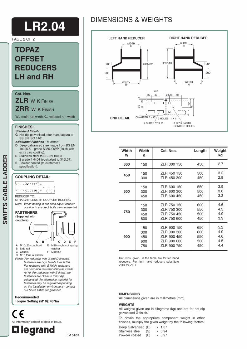
ZLR W K FINISH
ZRR W K FINISH
LR2.04
END DETAIL
PAGE 2 OF 2
OFFSETREDUCERSLH and RH
Weightkg
WidthK
150
150300
150300450
150300450600
150300450600750
450
750
WidthW
300
600
900
Cat. Nos.
ZLR 300 150
ZLR 450 150ZLR 450 300
ZLR 600 150ZLR 600 300ZLR 600 450
ZLR 750 150ZLR 750 300ZLR 750 450ZLR 750 600
ZLR 900 150ZLR 900 300ZLR 900 450ZLR 900 600ZLR 900 750
Length
450
500450
550500450
600550500450
650600550500450
2.7
3.22.9
3.93.63.3
4.64.34.03.9
5.24.94.64.54.4
W= main run width,K= reduced run width
Cat. Nos. given in the table are for left handreducers. For right hand reducers substituteZRR for ZLR.
DIMENSIONSAll dimensions given are in millimetres (mm).
WEIGHTSAll weights given are in kilograms (kg) and are for hot dipgalvanised G finish.
To obtain the appropriate component weight in otherfinishes, multiply the given weight by the following factors:
Deep Galvanised (D) x 1.07Stainless steel (S) x 0.94Powder coated (E) x 0.97
DIMENSIONS & WEIGHTS
10730 49 23 19 50
90 5020
5010
0
CHAMFER 7 x 45˚
4 SLOTS 37 X 13
2 HOLES 11 X 11
2 Ø 7.5 EARTHBONDING HOLES
5
REDUCER TOSTRAIGHT LENGTH COUPLER BOLTINGNote: When bolting to cut ends adjust coupler
position to ensure 2 bolts can be inserted.
Finish: For reducers with G and D finishes,fasteners are high tensile Grade 8.8.For reducers with S finish, fastenersare corrosion resistant stainless GradeA470. For reducers with E finish, thefasteners are Grade 8.8 hot dipgalvanised. An alternative material forfasteners may be required dependingon the installation environment - contactour Sales Office for guidance.
RecommendedTorque Setting (M10): 40Nm
WIDTHK
WIDTHW
LEFT HAND REDUCER
LENGTH
200
20°
WIDTHK
WIDTHW
RIGHT HAND REDUCER
LENGTH
200
20°

Cat. Nos.
TOPAZ
SW
IFT
S C
AB
LE
LA
DD
ER
FINISHES:Standard Finish:G Hot dip galvanised after manufacture to
BS EN ISO 1461.Additional Finishes - to order:D Deep galvanised steel made from BS EN
10025-5 – grade S355JOWP (finish withextra zinc coating).
S Stainless steel to BS EN 10088 -2 grade 1·4404 (equivalent to 316L31).
E Powder coated (to customer'sspecification).
COUPLING DETAIL:
(Supplied withcouplers):
FASTENERS
A B C D E FA M10x20 coachboltB Side railC CouplerD M10 form A washer
E M10 single coil springwasher
F M10 nut
EM 04/09
All information correct at date of issue.
LR2.05PAGE 1 OF 1
EQUAL TEES
W = width
Y80
80
RADIUS
i
WIDTHW
WIDTHW
X
A A
A
END DETAILQuantity and spacing of rungs varies with radiusand width. Nominal pitch = 300. Additional rungs (A)are fitted on tees of 600 radius and above.
For information on the use ofX, Y and i dimensions, referto Data Sheets LR7.03 andLR7.04.
WEIGHTSAll weights given are in kilograms (kg) and are for hot dipgalvanised G finish.
To obtain the appropriate component weight in otherfinishes, multiply the given weight by the following factors:
Deep Galvanised (D) x 1.07Stainless steel (S) x 0.94Powder coated (E) x 0.97
DIMENSIONSAll dimensions givenare in millimetres (mm).
Weightkg
Rad
300450600750900
300450600750900
300450600750900
300450600750900
300450600750900
300450600750(1)
900(1)
Y
454604754904
1054
529679829979
1129
604754904
10541204
679829979
11291279
754904
105412041354
829979
112912791429
X
454604754904
1054
529679829979
1129
604754904
10541204
679829979
11291279
754904
105412041354
829979
112912791429
i
537750962
11741386
537750962
11741386
537750962
11741386
537750962
11741386
537750962
11741386
537750962
11741386
5.87.59.8
11.913.8
7.09.0
11.613.916.2
8.410.714.416.319.0
11.013.717.120.021.9
13.116.020.922.829.0
15.919.123.329.832.2
Cat. Nos.
ZT 150 300RZT 150 450RZT 150 600RZT 150 750RZT 150 900R
ZT 300 300RZT 300 450RZT 300 600RZT 300 750RZT 300 900R
ZT 450 300RZT 450 450RZT 450 600RZT 450 750RZT 450 900R
ZT 600 300RZT 600 450RZT 600 600RZT 600 750RZT 600 900R
ZT 750 300RZT 750 450RZT 750 600RZT 750 750RZT 750 900R
ZT 900 300RZT 900 450RZT 900 600RZT 900 750RZT 900 900R
WidthW
150
300
450
600
750
900
ZT W RADR FINISH
DIMENSIONS & WEIGHTS
10730 49 23 19 50
90 5020
5010
0
CHAMFER 7 x 45˚
4 SLOTS 37 X 13
2 HOLES 11 X 11
2 Ø 7.5 EARTHBONDING HOLES
5
Finish: For tees with G and D finishes,fasteners are high tensile Grade 8.8.For tees with S finish, fastenersare corrosion resistant stainless GradeA470. For tees with E finish, thefasteners are Grade 8.8 hot dipgalvanised. An alternative material forfasteners may be required dependingon the installation environment - contactour Sales Office for guidance.
RecommendedTorque Setting (M10): 40Nm
EQUAL TEE TOSTRAIGHT LENGTH COUPLER BOLTINGNote: When bolting to cut ends adjust coupler
position to ensure 2 bolts can be inserted.
(1) Supplied in 2 parts for assembly on site

Cat. Nos.
TOPAZ
FINISHES:Standard Finish:G Hot dip galvanised after manufacture to
BS EN ISO 1461.Additional Finishes - to order:D Deep galvanised steel made from BS EN
10025-5 – grade S355JOWP (finish withextra zinc coating).
S Stainless steel to BS EN 10088 -2 grade 1·4404 (equivalent to 316L31).
E Powder coated (to customer'sspecification).
COUPLING DETAIL:
(Supplied withcouplers):
FASTENERS
A B C D E FA M10x20 coachboltB Side railC CouplerD M10 form A washer
E M10 single coil springwasher
F M10 nut
EM 04/09
All information correct at date of issue.
SW
IFT
S C
AB
LE
LA
DD
ER
Quantity and spacing of rungs varies withradius and width, nominal pitch = 300.
Additional rungs (A) are fitted on tees of600 radius and above.
For information on the use of X, Y, and idimensions, refer to Data Sheets LR7.03and LR7.04.
END DETAIL
DIMENSIONSAll dimensions given arein millimetres (mm).
WEIGHTSAll weights given are in kilograms (kg) and are for hot dipgalvanised G finish.
To obtain the appropriate component weight in otherfinishes, multiply the given weight by the following factors:
Deep Galvanised (D) x 1.07Stainless steel (S) x 0.94Powder coated (E) x 0.97
LR2.06PAGE 1 OF 4
UNEQUALTEES
Weightkg
Y
453603753903
1053
453603753903
1053
453603753903
1053
453603753903
1053
453603753903
1053
X
528678828978
1128
603753903
10531203
678828978
11281278
753903
105312031353
828978
112812781428
WidthB
300
450
600
750
900
Rad
300450600750900
300450600750900
300450600750900
300450600750900
300450600750900
i
537750962
11741386
537750962
11741386
537750962
11741386
537750962
11741386
537750962
11741386
6.58.4
10.712.714.9
7.29.1
11.813.615.7
8.110.112.814.916.8
8.910.914.115.918.1
9.811.814.917.119.0
WidthW
150
B = branch width
Cat. Nos.
ZUT 150 300 300RZUT 150 300 450RZUT 150 300 600RZUT 150 300 750RZUT 150 300 900R
ZUT 150 450 300RZUT 150 450 450RZUT 150 450 600RZUT 150 450 750RZUT 150 450 900R
ZUT 150 600 300RZUT 150 600 450RZUT 150 600 600RZUT 150 600 750RZUT 150 600 900R
ZUT 150 750 300RZUT 150 750 450RZUT 150 750 600RZUT 150 750 750RZUT 150 750 900R
ZUT 150 900 300RZUT 150 900 450RZUT 150 900 600RZUT 150 900 750RZUT 150 900 900R
ZUT 150 B RADR FINISH
DIMENSIONS & WEIGHTS
10730 49 23 19 50
90 5020
5010
0
CHAMFER 7 x 45˚
4 SLOTS 37 X 13
2 HOLES 11 X 11
2 Ø 7.5 EARTHBONDING HOLES
5
Finish: For tees with G and D finishes,fasteners are high tensile Grade 8.8.For tees with S finish, fastenersare corrosion resistant stainless GradeA470. For tees with E finish, thefasteners are Grade 8.8 hot dipgalvanised. An alternative material forfasteners may be required dependingon the installation environment - contactour Sales Office for guidance.
RecommendedTorque Setting (M10): 40Nm
UNEQUAL TEE TOSTRAIGHT LENGTH COUPLER BOLTINGNote: When bolting to cut ends adjust coupler
position to ensure 2 bolts can be inserted.
Y
80
80RADIUS
i
X
A
A
A
WIDTHW
WIDTHB

Cat. Nos.
TOPAZ
FINISHES:Standard Finish:G Hot dip galvanised after manufacture to
BS EN ISO 1461.Additional Finishes - to order:D Deep galvanised steel made from BS EN
10025-5 – grade S355JOWP (finish withextra zinc coating).
S Stainless steel to BS EN 10088 -2 grade 1·4404 (equivalent to 316L31).
E Powder coated (to customer'sspecification).
COUPLING DETAIL:
(Supplied withcouplers):
FASTENERS
A B C D E FA M10x20 coachboltB Side railC CouplerD M10 form A washer
E M10 single coil springwasher
F M10 nut
EM 04/09
All information correct at date of issue.
SW
IFT
S C
AB
LE
LA
DD
ER
B = branch width
LR2.06PAGE 2 OF 4
UNEQUALTEES
Weightkg
WidthW
300
450
Y
528678828978
1128
528678828978
1128
528678828978
1128
528678828978
1128
528678828978
1128
603753903
10531203
603753903
10531203
603753903
10531203
603753903
10531203
603753903
10531203
X
453603753903
1053
603753903
10531203
678828978
11281278
753903
105312031353
828978
112812781428
453603753903
1053
528678828978
1128
678828978
11281278
753903
105312031353
828978
112812781428
WidthB
150
450
600
750
900
150
300
600
750
900
Rad
300450600750900
300450600750900
300450600750900
300450600750900
300450600750900
300450600750900
300450600750900
300450600750900
300450600750900
300450600750900
i
537750962
11741386
537750962
11741386
537750962
11741386
537750962
11741386
537750962
11741386
537750962
11741386
537750962
11741386
537750962
11741386
537750962
11741386
537750962
11741386
6.38.0
10.713.015.0
7.79.8
12.914.717.1
8.710.813.916.218.1
9.511.615.417.319.7
10.512.616.218.620.5
7.08.7
12.014.616.6
7.69.9
12.915.518.2
9.611.915.518.220.1
10.412.817.319.222.0
11.614.018.120.922.8
DIMENSIONSAll dimensions given arein millimetres (mm).
WEIGHTSAll weights given are in kilograms (kg) and are for hot dipgalvanised G finish.
To obtain the appropriate component weight in otherfinishes, multiply the given weight by the following factors:
Deep Galvanised (D) x 1.07Stainless steel (S) x 0.94Powder coated (E) x 0.97
Cat. Nos.
ZUT 300 150 300RZUT 300 150 450RZUT 300 150 600RZUT 300 150 750RZUT 300 150 900R
ZUT 300 450 300RZUT 300 450 450RZUT 300 450 600RZUT 300 450 750RZUT 300 450 900R
ZUT 300 600 300RZUT 300 600 450RZUT 300 600 600RZUT 300 600 750RZUT 300 600 900R
ZUT 300 750 300RZUT 300 750 450RZUT 300 750 600RZUT 300 750 750RZUT 300 750 900R
ZUT 300 900 300RZUT 300 900 450RZUT 300 900 600RZUT 300 900 750RZUT 300 900 900R
ZUT 450 150 300RZUT 450 150 450RZUT 450 150 600RZUT 450 150 750RZUT 450 150 900R
ZUT 450 300 300RZUT 450 300 450RZUT 450 300 600RZUT 450 300 750RZUT 450 300 900R
ZUT 450 600 300RZUT 450 600 450RZUT 450 600 600RZUT 450 600 750RZUT 450 600 900R
ZUT 450 750 300RZUT 450 750 450RZUT 450 750 600RZUT 450 750 750RZUT 450 750 900R
ZUT 450 900 300RZUT 450 900 450RZUT 450 900 600RZUT 450 900 750RZUT 450 900 900R
ZUT 300 B RADR FINISH
ZUT 450 B RADR FINISH
DIMENSIONS & WEIGHTS
Finish: For tees with G and D finishes,fasteners are high tensile Grade 8.8.For tees with S finish, fastenersare corrosion resistant stainless GradeA470. For tees with E finish, thefasteners are Grade 8.8 hot dipgalvanised. An alternative material forfasteners may be required dependingon the installation environment - contactour Sales Office for guidance.
RecommendedTorque Setting (M10): 40Nm
UNEQUAL TEE TOSTRAIGHT LENGTH COUPLER BOLTINGNote: When bolting to cut ends adjust coupler
position to ensure 2 bolts can be inserted.

SW
IFT
S C
AB
LE
LA
DD
ER
Cat. Nos.
TOPAZ
FINISHES:Standard Finish:G Hot dip galvanised after manufacture to
BS EN ISO 1461.Additional Finishes - to order:D Deep galvanised steel made from BS EN
10025-5 – grade S355JOWP (finish withextra zinc coating).
S Stainless steel to BS EN 10088 -2 grade 1·4404 (equivalent to 316L31).
E Powder coated (to customer'sspecification).
COUPLING DETAIL:
(Supplied withcouplers):
FASTENERS
A B C D E FA M10x20 coachboltB Side railC CouplerD M10 form A washer
E M10 single coil springwasher
F M10 nut
EM 04/09
All information correct at date of issue.
END DETAIL
Quantity and spacing of rungs varies withradius and width, nominal pitch = 300.
Additional rungs (A) are fitted on tees of600 radius and above.
For information on the use of X, Y, and idimensions, refer to Data Sheets LR7.03and LR7.04.
WEIGHTSAll weights given are in kilograms (kg) and are for hot dipgalvanised G finish.
To obtain the appropriate component weight in otherfinishes, multiply the given weight by the following factors:
Deep Galvanised (D) x 1.07Stainless steel (S) x 0.94Powder coated (E) x 0.97
DIMENSIONSAll dimensions given arein millimetres (mm).
LR2.06PAGE 3 OF 4
UNEQUALTEES
WidthB
150
300
450
750
900
8.19.8
13.516.218.3
8.711.414.317.120.1
9.512.116.118.020.9
11.814.619.121.024.0
13.316.120.022.924.9
Weightkg
Y
678828978
11281278
678828978
11281278
678828978
11281278
678828978
11281278
678828978
11281278
X
453603753903
1053
528678828978
1128
603753903
10531203
753903
105312031353
828978
112812781428
Rad
300450600750900
300450600750900
300450600750900
300450600750900
300450600750900
i
537750962
11741386
537750962
11741386
537750962
11741386
537750962
11741386
537750962
11741386
WidthW
600
Cat. Nos.
ZUT 600 150 300RZUT 600 150 450RZUT 600 150 600RZUT 600 150 750RZUT 600 150 900R
ZUT 600 300 300RZUT 600 300 450RZUT 600 300 600RZUT 600 300 750RZUT 600 300 900R
ZUT 600 450 300RZUT 600 450 450RZUT 600 450 600RZUT 600 450 750RZUT 600 450 900R
ZUT 600 750 300RZUT 600 750 450RZUT 600 750 600RZUT 600 750 750RZUT 600 750 900R
ZUT 600 900 300RZUT 600 900 450RZUT 600 900 600RZUT 600 900 750RZUT 600 900 900R
ZUT 600 B RADR FINISH
DIMENSIONS & WEIGHTS
10730 49 23 19 50
90 5020
5010
0
CHAMFER 7 x 45˚
4 SLOTS 37 X 13
2 HOLES 11 X 11
2 Ø 7.5 EARTHBONDING HOLES
5
B = branch width
Finish: For tees with G and D finishes,fasteners are high tensile Grade 8.8. Fortees with S finish, fasteners arecorrosion resistant stainless GradeA470. For tees with E finish, thefasteners are Grade 8.8 hot dipgalvanised. An alternative material forfasteners may be required depending onthe installation environment - contact ourSales Office for guidance.
RecommendedTorque Setting (M10): 40Nm
UNEQUAL TEE TOSTRAIGHT LENGTH COUPLER BOLTINGNote: When bolting to cut ends adjust coupler
position to ensure 2 bolts can be inserted.
Y
80
80RADIUS
i
X
A
A
A
WIDTHW
WIDTHB

Cat. Nos.
TOPAZ
FINISHES:Standard Finish:G Hot dip galvanised after manufacture to
BS EN ISO 1461.Additional Finishes - to order:D Deep galvanised steel made from BS EN
10025-5 – grade S355JOWP (finish withextra zinc coating).
S Stainless steel to BS EN 10088 -2 grade 1·4404 (equivalent to 316L31).
E Powder coated (to customer'sspecification).
COUPLING DETAIL:
(Supplied withcouplers):
FASTENERS
A B C D E FA M10x20 coachboltB Side railC CouplerD M10 form A washer
E M10 single coil springwasher
F M10 nut
EM 04/09
All information correct at date of issue.
SW
IFT
S C
AB
LE
LA
DD
ER
LR2.06PAGE 4 OF 4
UNEQUALTEES
B = branch width
WidthW
750
900
(For illustration see previous page).
Weightkg
Y
753903
105312031353
753903
105312031353
753903
105312031353
753903
105312031353
753903
105312031353
828978
112812781428
828978
112812781386
828978
112812781428
828978
112812781428
828978
112812781428
X
453603753903
1053
528678828978
1128
603753903
10531203
678828978
11281278
828978
112812781428
453603753903
1053
528678828978
1128
603753903
10531203
678828978
11281278
753903
105312031353
WidthB
150
300
450
600
900
150
300
450
600
750
Rad
300450600750900(1)
300450600750900(1)
300450600750900(1)
300450600750900(1)
300450600750900(1)
300450600750(1)
900(1)
300450600750(1)
900(1)
300450600750(1)
900(1)
300450600750(1)
900(1)
300450600750(1)
900(1)
Cat. Nos.
ZUT 750 150 300RZUT 750 150 450RZUT 750 150 600RZUT 750 150 750RZUT 750 150 900R
ZUT 750 300 300RZUT 750 300 450RZUT 750 300 600RZUT 750 300 750RZUT 750 300 900R
ZUT 750 450 300RZUT 750 450 450RZUT 750 450 600RZUT 750 450 750RZUT 750 450 900R
ZUT 750 600 300RZUT 750 600 450RZUT 750 600 600RZUT 750 600 750RZUT 750 600 900R
ZUT 750 900 300RZUT 750 900 450RZUT 750 900 600RZUT 750 900 750RZUT 750 900 900R
ZUT 900 150 300RZUT 900 150 450RZUT 900 150 600RZUT 900 150 750RZUT 900 150 900R
ZUT 900 300 300RZUT 900 300 450RZUT 900 300 600RZUT 900 300 750RZUT 900 300 900R
ZUT 900 450 300RZUT 900 450 450RZUT 900 450 600RZUT 900 450 750RZUT 900 450 900R
ZUT 900 600 300RZUT 900 600 450RZUT 900 600 600RZUT 900 600 750RZUT 900 600 900R
ZUT 900 750 300RZUT 900 750 450RZUT 900 750 600RZUT 900 750 750RZUT 900 750 900R
i
537750962
11741386
537750962
11741386
537750962
11741386
537750962
11741386
537750962
11741386
537750962
11741386
537750962
11741386
537750962
11741386
537750962
11741386
537750962
11741386
9.210.914.917.923.7
9.812.615.818.824.3
10.513.417.719.627.5
12.315.218.821.828.3
14.817.721.824.930.2
9.911.616.023.025.3
10.513.516.923.726.0
11.314.319.024.429.5
13.216.320.127.930.3
14.017.122.428.631.0
WEIGHTSAll weights given are in kilograms (kg) and are for hot dipgalvanised G finish.
To obtain the appropriate component weight in otherfinishes, multiply the given weight by the following factors:
Deep Galvanised (D) x 1.07Stainless steel (S) x 0.94Powder coated (E) x 0.97
DIMENSIONSAll dimensions givenare in millimetres (mm).
ZUT 750 B RADR FINISH
ZUT 900 B RADR FINISH
DIMENSIONS & WEIGHTS
Finish: For tees with G and D finishes,fasteners are high tensile Grade 8.8.For tees with S finish, fastenersare corrosion resistant stainless GradeA470. For tees with E finish, thefasteners are Grade 8.8 hot dipgalvanised. An alternative material forfasteners may be required dependingon the installation environment - contactour Sales Office for guidance.
RecommendedTorque Setting (M10): 40Nm
UNEQUAL TEE TOSTRAIGHT LENGTH COUPLER BOLTINGNote: When bolting to cut ends adjust coupler
position to ensure 2 bolts can be inserted.
(1) Supplied in 2 parts for assembly on site
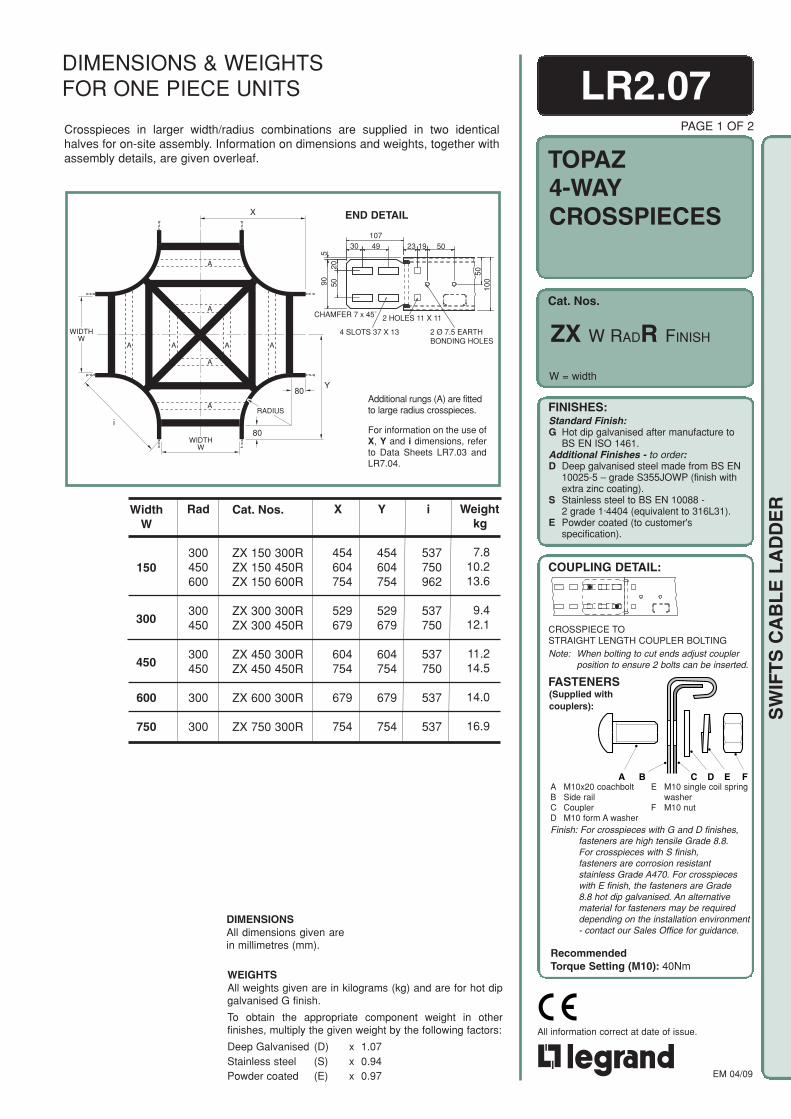
Cat. Nos.
TOPAZ
FINISHES:Standard Finish:G Hot dip galvanised after manufacture to
BS EN ISO 1461.Additional Finishes - to order:D Deep galvanised steel made from BS EN
10025-5 – grade S355JOWP (finish withextra zinc coating).
S Stainless steel to BS EN 10088 -2 grade 1·4404 (equivalent to 316L31).
E Powder coated (to customer'sspecification).
COUPLING DETAIL:
(Supplied withcouplers):
FASTENERS
A B C D E FA M10x20 coachboltB Side railC CouplerD M10 form A washer
E M10 single coil springwasher
F M10 nut
EM 04/09
All information correct at date of issue.
SW
IFT
S C
AB
LE
LA
DD
ER
DIMENSIONS & WEIGHTSFOR ONE PIECE UNITS
Y80
80
RADIUS
i
WIDTHW
WIDTHW
X
A A
A
A
A A
A
A
END DETAIL
Additional rungs (A) are fittedto large radius crosspieces.
For information on the use ofX, Y and i dimensions, referto Data Sheets LR7.03 andLR7.04.
Weightkg
i
537750962
537750
537750
537
537
Rad
300450600
300450
300450
300
300
Y
454604754
529679
604754
679
754
X
454604754
529679
604754
679
754
7.810.213.6
9.412.1
11.214.5
14.0
16.9
Cat. Nos.
ZX 150 300RZX 150 450RZX 150 600R
ZX 300 300RZX 300 450R
ZX 450 300RZX 450 450R
ZX 600 300R
ZX 750 300R
WidthW
150
300
450
600
750
DIMENSIONSAll dimensions given arein millimetres (mm).
WEIGHTSAll weights given are in kilograms (kg) and are for hot dipgalvanised G finish.
To obtain the appropriate component weight in otherfinishes, multiply the given weight by the following factors:
Deep Galvanised (D) x 1.07Stainless steel (S) x 0.94Powder coated (E) x 0.97
LR2.07PAGE 1 OF 2
4-WAYCROSSPIECES
W = width
ZX W RADR FINISH
Crosspieces in larger width/radius combinations are supplied in two identicalhalves for on-site assembly. Information on dimensions and weights, together withassembly details, are given overleaf.
10730 49 23 19 50
90 5020
5010
0
CHAMFER 7 x 45˚
4 SLOTS 37 X 13
2 HOLES 11 X 11
2 Ø 7.5 EARTHBONDING HOLES
5
CROSSPIECE TOSTRAIGHT LENGTH COUPLER BOLTINGNote: When bolting to cut ends adjust coupler
position to ensure 2 bolts can be inserted.
Finish: For crosspieces with G and D finishes,fasteners are high tensile Grade 8.8.For crosspieces with S finish,fasteners are corrosion resistantstainless Grade A470. For crosspieceswith E finish, the fasteners are Grade8.8 hot dip galvanised. An alternativematerial for fasteners may be requireddepending on the installation environment- contact our Sales Office for guidance.
RecommendedTorque Setting (M10): 40Nm

Cat. Nos.
TOPAZ
FINISHES:Standard Finish:G Hot dip galvanised after manufacture to
BS EN ISO 1461.Additional Finishes - to order:D Deep galvanised steel made from BS EN
10025-5 – grade S355JOWP (finish withextra zinc coating).
S Stainless steel to BS EN 10088 -2 grade 1·4404 (equivalent to 316L31).
E Powder coated (to customer'sspecification).
EM 04/09
All information correct at date of issue.
SW
IFT
S C
AB
LE
LA
DD
ER
LR2.07PAGE 2 OF 2
DIMENSIONS & WEIGHTSFOR TWO PIECE UNITS
For information on the use of X, Y andi dimensions, refer to Data SheetsLR7.03 and LR7.04.
80
80
RADIUS
i
WIDTHW
X
Y
A
Y
END DETAIL
WEIGHTSAll weights given are in kilograms (kg) and are for hot dipgalvanised G finish.
To obtain the appropriate component weight in otherfinishes, multiply the given weight by the following factors:Deep Galvanised (D) x 1.07Stainless steel (S) x 0.94Powder coated (E) x 0.97
DIMENSIONS All dimensions given arein millimetres (mm).
4-WAYCROSSPIECES
W = width
ZX W RADR FINISH
10730 49 23 19 50
90 5020
5010
0CHAMFER 7 x 45˚
4 SLOTS 37 X 13
2 HOLES 11 X 11
2 Ø 7.5 EARTHBONDING HOLES
5
ASSEMBLY DETAIL FORTWO PIECE UNITS - detail A(Fasteners included):
A B C DC
A M6 nutB Shakeproof washerC Flat washer
- roofing washers for /G and /D- form A for /S
D M6x16 set screw
Finish: For crosspieces with G and D finishes,fasteners are high tensile Grade 8.8.For crosspieces with S finish,fasteners are corrosion resistantstainless Grade A470. For crosspieceswith E finish, the fasteners are Grade8.8 hot dip galvanised. An alternativematerial for fasteners may be requireddepending on the installation environment- contact our Sales Office for guidance.
RecommendedTorque Setting (M10): 40Nm
Weightkg
i
11741386
96211741386
96211741386
750962
11741386
750962
11741386
537750962
11741386
Rad
750900
600750900
600750900
450600750900
450600750900
300450600750900
Y
9041054
829979
1129
90410541204
829979
11291279
904105412041354
829979
112912791429
X
9041054
829979
1129
90410541204
829979
11291279
904105412041354
829979
112912791429
20.824.5
15.923.327.3
22.325.729.8
16.625.129.333.5
22.029.432.937.6
19.025.732.137.242.5
Cat. Nos.
ZX 150 750RZX 150 900R
ZX 300 600RZX 300 750RZX 300 900R
ZX 450 600RZX 450 750RZX 450 900R
ZX 600 450RZX 600 600RZX 600 750RZX 600 900R
ZX 750 450RZX 750 600RZX 750 750RZX 750 900R
ZX 900 300RZX 900 450RZX 900 600RZX 900 750RZX 900 900R
WidthW
150
300
900
450
600
750
Assembly detail for two pieceunits - detail A, see below.

Cat. Nos.
SAPPHIRESTRAIGHTLENGTHS
FINISHES:Standard Finish:G Hot dip galvanised after manufacture to
BS EN ISO 1461.Additional Finishes - to order:D Deep galvanised steel made from BS EN
10025-5 – grade S355JOWP (finish withextra zinc coating).
S Stainless steel to BS EN 10088 -2 grade 1·4404 (equivalent to 316L31).
E Powder coated (to customer'sspecification).
COUPLING DETAIL:
(Supplied withcouplers):
FASTENERS
A M10x20 coachboltB Side railC CouplerD M10 form A washer
E M10 single coil springwasher
F M10 nut
A B C D E F
RecommendedTorque Setting (M10): 40Nm
Also refer toData SheetLR6.01.
Note: When bolting to cut ends adjust couplerposition to ensure 8 bolts can be inserted.
EM 04/09
All information correct at date of issue.
SW
IFT
S C
AB
LE
LA
DD
ER
ACTUALSIZE
For cable load capacity seeloading graphs.
WidthW
150
300
450
600
750
900
13.8
15.0
16.3
18.5
22.0
23.9
PL 150
PL 300
PL 450
PL 600
PL 750
PL 900
Weightkg
Cat. Nos.
LR3.01PAGE 1 OF 1
W = width
DIMENSIONSAll dimensions given are inmillimetres (mm).
WEIGHTSAll weights given are in kilograms(kg) and are for a 3m straightlength in a hot dip galvanised Gfinish.
To obtain the appropriatecomponent weight in otherfinishes, multiply the given weightby the following factors:
Deep Galvanised (D) x 1.07Stainless steel (S) x 0.94Powder coated (E) x 0.97
PL W FINISH 6mPL W FINISH
DIMENSIONS & WEIGHTS
Type 1 rungs are used as standard. Fordetails of these, and other available rungoptions, refer to Data Sheet LR7.01.
1.5STRAIGHT LENGTH TOSTRAIGHT LENGTH COUPLER BOLTING
Finish: For ladders with G and D finishes,fasteners are high tensile Grade 8.8.For ladders with S finish, fastenersare corrosion resistant stainless GradeA470. For ladders with E finish, thefasteners are Grade 8.8 hot dipgalvanised. An alternative material forfasteners may be required depending onthe installation environment - contact ourSales Office for guidance.

Cat. Nos.
SAPPHIRE
FINISHES:Standard Finish:G Hot dip galvanised after manufacture to
BS EN ISO 1461.Additional Finishes - to order:D Deep galvanised steel made from BS EN
10025-5 – grade S355JOWP (finish withextra zinc coating).
S Stainless steel to BS EN 10088 -2 grade 1·4404 (equivalent to 316L31).
E Powder coated (to customer'sspecification).
COUPLING DETAIL:
(Supplied withcouplers):
FASTENERS
A M10x20 coachboltB Side railC CouplerD M10 form A washer
E M10 single coil springwasher
F M10 nut
A B C D E F
RecommendedTorque Setting (M10): 40Nm
Note: When bolting to cut ends adjust couplerposition to ensure 4 bolts can be inserted.
EM 04/09
All information correct at date of issue.
SW
IFT
S C
AB
LE
LA
DD
ER
LR3.02PAGE 1 OF 4
90°FLAT BENDS
W = width
X
80
i
80
C
WIDTH
Y
RADIUS
END DETAIL
For information on the use of X, Y, i andC dimensions, refer to Data SheetsLR7.03 and LR7.04.
Weightkg
Cat. Nos.
PFB 150 90 300PFB 150 90 450PFB 150 90 600PFB 150 90 750PFB 150 90 900
PFB 300 90 300PFB 300 90 450PFB 300 90 600PFB 300 90 750PFB 300 90 900
PFB 450 90 300PFB 450 90 450PFB 450 90 600PFB 450 90 750PFB 450 90 900
PFB 600 90 300PFB 600 90 450PFB 600 90 600PFB 600 90 750PFB 600 90 900
PFB 750 90 300PFB 750 90 450PFB 750 90 600PFB 750 90 750PFB 750 90 900
PFB 900 90 300PFB 900 90 450PFB 900 90 600PFB 900 90 750PFB 900 90 900
Y
453603753903
1053
528678828978
1128
603753903
10531203
678828978
11281278
753903
105312031353
828978
112812781428
i
537750962
11741386
537750962
11741386
537750962
11741386
537750962
11741386
537750962
11741386
537750962
11741386
C
453603753903
1053
528678828978
1128
603753903
10531203
678828978
11281278
753903
105312031353
828978
112812781428
No. ofRungs
33444
33445
34455
44555
45556
55566
X
453603753903
1053
528678828978
1128
603753903
10531203
678828978
11281278
753903
105312031353
828978
112812781428
Rad
300450600750900
300450600750900
300450600750900
300450600750900
300450600750900
300450600750900
WidthW
150
300
450
600
750
900
DIMENSIONSAll dimensions given arein millimetres (mm).
PFB W 90 RAD FINISH
4.35.46.67.78.8
5.26.37.78.8
10.1
6.17.68.7
10.211.3
8.09.1
10.811.812.9
9.911.913.014.116.1
12.313.414.516.717.8
WEIGHTSAll weights given are in kilograms (kg) and are for hot dipgalvanised G finish.
To obtain the appropriate component weight in other finishes,multiply the given weight by the following factors:
Deep Galvanised (D) x 1.07Stainless steel (S) x 0.94Powder coated (E) x 0.97
DIMENSIONS & WEIGHTS
107
30 49 25 19 50
511
5
2050
CHAMFER 7 x 45°4 SLOTS 37 x13
4 HOLES 11 x11
2 Ø 7.5 EARTHBONDING HOLES
50
125
FLAT BEND TOSTRAIGHT LENGTH COUPLER BOLTING
Finish: For bends with G and D finishes,fasteners are high tensile Grade 8.8. Forbends with S finish, fastenersare corrosion resistant stainless GradeA470. For bends with E finish, thefasteners are Grade 8.8 hot dipgalvanised. An alternative material forfasteners may be required depending onthe installation environment - contact ourSales Office for guidance.

Cat. Nos.
SAPPHIRE
FINISHES:Standard Finish:G Hot dip galvanised after manufacture to
BS EN ISO 1461.Additional Finishes - to order:D Deep galvanised steel made from BS EN
10025-5 – grade S355JOWP (finish withextra zinc coating).
S Stainless steel to BS EN 10088 -2 grade 1·4404 (equivalent to 316L31).
E Powder coated (to customer'sspecification).
COUPLING DETAIL:
(Supplied withcouplers):
FASTENERS
A M10x20 coachboltB Side railC CouplerD M10 form A washer
E M10 single coil springwasher
F M10 nut
A B C D E F
RecommendedTorque Setting (M10): 40Nm
Note: When bolting to cut ends adjust couplerposition to ensure 4 bolts can be inserted.
EM 04/09
All information correct at date of issue.
SW
IFT
S C
AB
LE
LA
DD
ER
END DETAIL
80
80RADIUS
C
WIDTH
Y
iX
For information on the use of X, Y, i andC dimensions, refer to Data SheetsLR7.03 and LR7.04.
WEIGHTSAll weights given are in kilograms (kg) and are for hot dipgalvanised G finish.
To obtain the appropriate component weight in other finishes,multiply the given weight by the following factors:
Deep Galvanised (D) x 1.07Stainless steel (S) x 0.94Powder coated (E) x 0.97
X
443573703833963
508638768898
1028
573703833963
1093
638768898
10281157
703833963
10931222
768898
102811571287
Weightkg
Cat. Nos.
PFB 150 60 300PFB 150 60 450PFB 150 60 600PFB 150 60 750PFB 150 60 900
PFB 300 60 300PFB 300 60 450PFB 300 60 600PFB 300 60 750PFB 300 60 900
PFB 450 60 300PFB 450 60 450PFB 450 60 600PFB 450 60 750PFB 450 60 900
PFB 600 60 300PFB 600 60 450PFB 600 60 600PFB 600 60 750PFB 600 60 900
PFB 750 60 300PFB 750 60 450PFB 750 60 600PFB 750 60 750PFB 750 60 900
PFB 900 60 300PFB 900 60 450PFB 900 60 600PFB 900 60 750PFB 900 60 900
Y
256331406481556
294369444519594
331406481556631
368443518593668
406481556631706
443518593668743
i
439589739889
1039
439589739889
1039
439589739889
1039
439589739889
1039
439589739889
1039
439589739889
1039
C
296382469555642
339426512599685
382469555642728
426512599685772
469555642729815
512598685772858
No. ofRungs
23333
33334
33344
33444
34444
44445
3.34.14.95.66.3
4.14.95.66.37.3
4.95.66.37.48.2
5.96.78.08.79.4
7.39.09.7
10.411.2
9.410.110.811.613.4
Rad
300450600750900
300450600750900
300450600750900
300450600750900
300450600750900
300450600750900
WidthW
150
300
450
600
750
900
LR3.02
60°FLAT BENDS
W = width
PAGE 2 OF 4
DIMENSIONSAll dimensions given arein millimetres (mm).
PFB W 60 RAD FINISH
DIMENSIONS & WEIGHTS
107
30 49 25 19 50
511
5
2050
CHAMFER 7 x 45°4 SLOTS 37 x13
4 HOLES 11 x11
2 Ø 7.5 EARTHBONDING HOLES
50
125
FLAT BEND TOSTRAIGHT LENGTH COUPLER BOLTING
Finish: For bends with G and D finishes,fasteners are high tensile Grade 8.8.For bends with S finish, fastenersare corrosion resistant stainless GradeA470. For bends with E finish, thefasteners are Grade 8.8 hot dipgalvanised. An alternative material forfasteners may be required depending onthe installation environment - contact ourSales Office for guidance.

Cat. Nos.
SAPPHIRE
FINISHES:Standard Finish:G Hot dip galvanised after manufacture to
BS EN ISO 1461.Additional Finishes - to order:D Deep galvanised steel made from BS EN
10025-5 – grade S355JOWP (finish withextra zinc coating).
S Stainless steel to BS EN 10088 -2 grade 1·4404 (equivalent to 316L31).
E Powder coated (to customer'sspecification).
COUPLING DETAIL:
(Supplied withcouplers):
FASTENERS
A M10x20 coachboltB Side railC CouplerD M10 form A washer
E M10 single coil springwasher
F M10 nut
A B C D E F
RecommendedTorque Setting (M10): 40Nm
Note: When bolting to cut ends adjust couplerposition to ensure 4 bolts can be inserted.
EM 04/09
All information correct at date of issue.
SW
IFT
S C
AB
LE
LA
DD
ER
Weightkg
Cat. Nos.
PFB 150 45 300PFB 150 45 450PFB 150 45 600PFB 150 45 750PFB 150 45 900
PFB 300 45 300PFB 300 45 450PFB 300 45 600PFB 300 45 750PFB 300 45 900
PFB 450 45 300PFB 450 45 450PFB 450 45 600PFB 450 45 750PFB 450 45 900
PFB 600 45 300PFB 600 45 450PFB 600 45 600PFB 600 45 750PFB 600 45 900
PFB 750 45 300PFB 750 45 450PFB 750 45 600PFB 750 45 750PFB 750 45 900
PFB 900 45 300PFB 900 45 450PFB 900 45 600PFB 900 45 750PFB 900 45 900
Y
166210254298342
188232276320364
210254298342385
232276320364407
254298342385429
276320364407451
i
377492607722837
377492607722837
377492607722837
377492607722837
377492607722837
377492607722837
C
235297359421483
266328390452514
297359421483545
328390452514576
359421483545607
390452514576638
No. ofRungs
22233
22333
23333
33333
33334
33344
X
400506612719825
453559665772878
506612719825931
559665772878984
612719825931
1037
665772878984
1090
Rad
300450600750900
300450600750900
300450600750900
300450600750900
300450600750900
300450600750900
WidthW
150
300
450
600
750
900
X
80
i
80
RADIUS
C
WIDTH
Y
END DETAIL
For information on the use of X, Y, i andC dimensions, refer to Data SheetsLR7.03 and LR7.04.
LR3.02
45°FLAT BENDS
W = width
PAGE 3 OF 4
WEIGHTSAll weights given are in kilograms (kg) and are for hot dipgalvanised G finish.
To obtain the appropriate component weight in other finishes,multiply the given weight by the following factors:
Deep Galvanised (D) x 1.07Stainless steel (S) x 0.94Powder coated (E) x 0.97
DIMENSIONSAll dimensions given arein millimetres (mm).
2.83.43.94.65.1
3.43.94.75.25.8
3.94.85.35.96.4
5.25.76.36.87.4
6.57.07.68.19.6
7.37.98.4
10.110.6
PFB W 45 RAD FINISH
DIMENSIONS & WEIGHTS
107
30 49 25 19 50
511
5
2050
CHAMFER 7 x 45°4 SLOTS 37 x13
4 HOLES 11 x11
2 Ø 7.5 EARTHBONDING HOLES
50
125
FLAT BEND TOSTRAIGHT LENGTH COUPLER BOLTING
Finish: For bends with G and D finishes,fasteners are high tensile Grade 8.8.For bends with S finish, fastenersare corrosion resistant stainless GradeA470. For bends with E finish, thefasteners are Grade 8.8 hot dipgalvanised. An alternative material forfasteners may be required depending onthe installation environment - contact ourSales Office for guidance.
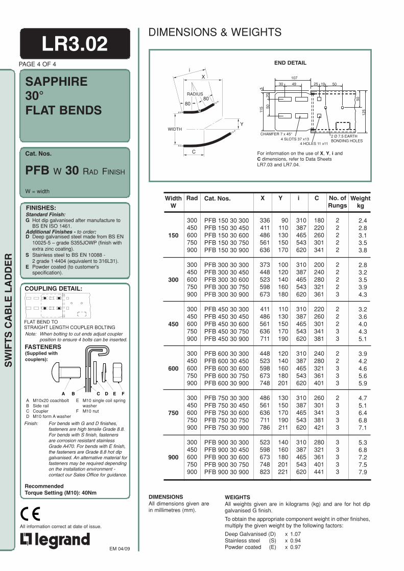
Cat. Nos.
SAPPHIRE
FINISHES:Standard Finish:G Hot dip galvanised after manufacture to
BS EN ISO 1461.Additional Finishes - to order:D Deep galvanised steel made from BS EN
10025-5 – grade S355JOWP (finish withextra zinc coating).
S Stainless steel to BS EN 10088 -2 grade 1·4404 (equivalent to 316L31).
E Powder coated (to customer'sspecification).
COUPLING DETAIL:
(Supplied withcouplers):
FASTENERS
A M10x20 coachboltB Side railC CouplerD M10 form A washer
E M10 single coil springwasher
F M10 nut
A B C D E F
RecommendedTorque Setting (M10): 40Nm
Note: When bolting to cut ends adjust couplerposition to ensure 4 bolts can be inserted.
EM 04/09
All information correct at date of issue.
SW
IFT
S C
AB
LE
LA
DD
ER
END DETAIL
For information on the use of X, Y, i andC dimensions, refer to Data SheetsLR7.03 and LR7.04.
X
80
i
80
RADIUS
C
WIDTHY
Weightkg
Cat. Nos.
PFB 150 30 300PFB 150 30 450PFB 150 30 600PFB 150 30 750PFB 150 30 900
PFB 300 30 300PFB 300 30 450PFB 300 30 600PFB 300 30 750PFB 300 30 900
PFB 450 30 300PFB 450 30 450PFB 450 30 600PFB 450 30 750PFB 450 30 900
PFB 600 30 300PFB 600 30 450PFB 600 30 600PFB 600 30 750PFB 600 30 900
PFB 750 30 300PFB 750 30 450PFB 750 30 600PFB 750 30 750PFB 750 30 900
PFB 900 30 300PFB 900 30 450PFB 900 30 600PFB 900 30 750PFB 900 30 900
Y
90110130150170
100120140160180
110130150170190
120140160180201
130150170190211
140160180201221
i
310387465543620
310387465543620
310387465543620
310387465543620
310387465543620
310387465543620
C
180220260301341
200240280321361
220260301341381
240280321361401
260301341381421
280321361401441
No. ofRungs
22222
22223
22233
22333
23333
33333
X
336411486561636
373448523598673
411486561636711
448523598673748
486561636711786
523598673748823
Rad
300450600750900
300450600750900
300450600750900
300450600750900
300450600750900
300450600750900
WidthW
150
300
450
600
750
900
LR3.02PAGE 4 OF 4
30°FLAT BENDS
W = width
WEIGHTSAll weights given are in kilograms (kg) and are for hot dipgalvanised G finish.
To obtain the appropriate component weight in other finishes,multiply the given weight by the following factors:
Deep Galvanised (D) x 1.07Stainless steel (S) x 0.94Powder coated (E) x 0.97
DIMENSIONSAll dimensions given arein millimetres (mm).
2.42.83.13.53.8
2.83.23.53.94.3
3.23.64.04.35.1
3.94.24.65.65.9
4.75.16.46.87.1
5.36.87.27.57.9
PFB W 30 RAD FINISH
DIMENSIONS & WEIGHTS
107
30 49 25 19 50
511
5
2050
CHAMFER 7 x 45°4 SLOTS 37 x13
4 HOLES 11 x11
2 Ø 7.5 EARTHBONDING HOLES
50
125
FLAT BEND TOSTRAIGHT LENGTH COUPLER BOLTING
Finish: For bends with G and D finishes,fasteners are high tensile Grade 8.8.For bends with S finish, fastenersare corrosion resistant stainlessGrade A470. For bends with E finish,the fasteners are Grade 8.8 hot dipgalvanised. An alternative material forfasteners may be required dependingon the installation environment -contact our Sales Office for guidance.

Cat. Nos.
SAPPHIRE
FINISHES:Standard Finish:G Hot dip galvanised after manufacture to
BS EN ISO 1461.Additional Finishes - to order:D Deep galvanised steel made from BS EN
10025-5 – grade S355JOWP (finish withextra zinc coating).
S Stainless steel to BS EN 10088 -2 grade 1·4404 (equivalent to 316L31).
E Powder coated (to customer'sspecification).
COUPLING DETAIL:
(Supplied withcouplers):
FASTENERS
A M10x20 coachboltB Side railC CouplerD M10 form A washer
E M10 single coil springwasher
F M10 nut
A B C D E F
RecommendedTorque Setting (M10): 40Nm
Note: When bolting to cut ends adjust couplerposition to ensure 4 bolts can be inserted.
EM 04/09
All information correct at date of issue.
SW
IFT
S C
AB
LE
LA
DD
ER
X,C
NOMINALRADIUS
R600
R750
R900
Y
4 sidesegmen ts
END DETAIL
NOMINALRADIUS
X,C
Y
R300
R450
3 sidesegmen ts
i For information on the use of X, Y, i andC dimensions, refer to Data SheetsLR7.03 and LR7.04.
LR3.03PAGE 1 OF 4
90° RISERSINSIDE &OUTSIDE
PIR W 90 RAD FINISH
POR W 90 RAD FINISH
W = width
Weightkg
Y
363513663813963
363513663813963
363513663813963
363513663813963
363513663813963
363513663813963
i
424636849
10611273
424636849
10611273
424636849
10611273
424636849
10611273
424636849
10611273
424636849
10611273
C
363513663813963
363513663813963
363513663813963
363513663813963
363513663813963
363513663813963
No. ofRungs
33444
33444
33444
33444
33444
33444
X
363513663813963
363513663813963
363513663813963
363513663813963
363513663813963
363513663813963
Rad
300450600750900
300450600750900
300450600750900
300450600750900
300450600750900
300450600750900
WidthW
150
300
450
600
750
900
Cat. Nos.
PIR 150 90 300PIR 150 90 450PIR 150 90 600PIR 150 90 750PIR 150 90 900
PIR 300 90 300PIR 300 90 450PIR 300 90 600PIR 300 90 750PIR 300 90 900
PIR 450 90 300PIR 450 90 450PIR 450 90 600PIR 450 90 750PIR 450 90 900
PIR 600 90 300PIR 600 90 450PIR 600 90 600PIR 600 90 750PIR 600 90 900
PIR 750 90 300PIR 750 90 450PIR 750 90 600PIR 750 90 750PIR 750 90 900
PIR 900 90 300PIR 900 90 450PIR 900 90 600PIR 900 90 750PIR 900 90 900
DIMENSIONSAll dimensions given arein millimetres (mm).
Cat. Nos. given in the table arefor inside risers.For outside risers substitutePOR for PIR.
WEIGHTSAll weights given are in kilograms (kg) and are for hot dipgalvanised G finish.
To obtain the appropriate component weight in other finishes,multiply the given weight by the following factors:
Deep Galvanised (D) x 1.07Stainless steel (S) x 0.94Powder coated (E) x 0.97
3.74.96.07.18.2
4.15.26.57.68.7
4.45.66.98.19.2
5.16.37.99.0
10.1
6.17.39.2
10.311.5
6.77.9
10.011.112.2
DIMENSIONS & WEIGHTS
107
30 49 25 19 50
511
5
2050
CHAMFER 7 x 45°4 SLOTS 37 x13
4 HOLES 11 x11
2 Ø 7.5 EARTHBONDING HOLES
50
125
RISER TOSTRAIGHT LENGTH COUPLER BOLTING
Finish: For risers with G and D finishes,fasteners are high tensile Grade 8.8.For risers with S finish, fasteners arecorrosion resistant stainless Grade A470.For risers with E finish, the fasteners areGrade 8.8 hot dip galvanised. Analternative material for fasteners may berequired depending on the installationenvironment - contact our Sales Office forguidance.

Cat. Nos.
SAPPHIRE
FINISHES:Standard Finish:G Hot dip galvanised after manufacture to
BS EN ISO 1461.Additional Finishes - to order:D Deep galvanised steel made from BS EN
10025-5 – grade S355JOWP (finish withextra zinc coating).
S Stainless steel to BS EN 10088 -2 grade 1·4404 (equivalent to 316L31).
E Powder coated (to customer'sspecification).
COUPLING DETAIL:
(Supplied withcouplers):
FASTENERS
A M10x20 coachboltB Side railC CouplerD M10 form A washer
E M10 single coil springwasher
F M10 nut
A B C D E F
RecommendedTorque Setting (M10): 40Nm
Note: When bolting to cut ends adjust couplerposition to ensure 4 bolts can be inserted.
EM 04/09
All information correct at date of issue.
SW
IFT
S C
AB
LE
LA
DD
ER
R300
R450
R900
NOMINALRADIUS
R600
R750
CX
Y
For information on the use of X, Y, i andC dimensions, refer to Data SheetsLR7.03 and LR7.04.
END DETAIL
Y
181256331406481
181256331406481
181256331406481
181256331406481
181256331406481
181256331406481
i
300450600750900
300450600750900
300450600750900
300450600750900
300450600750900
300450600750900
C
209296382469556
209296382469556
209296382469556
209296382469556
209296382469556
209296382469556
No. ofRungs
33333
33333
33333
33333
33333
33333
X
314444574704834
314444574704834
314444574704834
314444574704834
314444574704834
314444574704834
Rad
300450600750900
300450600750900
300450600750900
300450600750900
300450600750900
300450600750900
WidthW
150
300
450
600
750
900
Cat. Nos.
PIR 150 60 300PIR 150 60 450PIR 150 60 600PIR 150 60 750PIR 150 60 900
PIR 300 60 300PIR 300 60 450PIR 300 60 600PIR 300 60 750PIR 300 60 900
PIR 450 60 300PIR 450 60 450PIR 450 60 600PIR 450 60 750PIR 450 60 900
PIR 600 60 300PIR 600 60 450PIR 600 60 600PIR 600 60 750PIR 600 60 900
PIR 750 60 300PIR 750 60 450PIR 750 60 600PIR 750 60 750PIR 750 60 900
PIR 900 60 300PIR 900 60 450PIR 900 60 600PIR 900 60 750PIR 900 60 900
Weightkg
WEIGHTSAll weights given are in kilograms (kg) and are for hot dipgalvanised G finish.
To obtain the appropriate component weight in otherfinishes, multiply the given weight by the following factors:
Deep Galvanised (D) x 1.07Stainless steel (S) x 0.94Powder coated (E) x 0.97
DIMENSIONSAll dimensions given arein millimetres (mm).
Cat. Nos. given in the table arefor inside risers.For outside risers substitutePOR for PIR.
LR3.03PAGE 2 OF 4
60° RISERSINSIDE &OUTSIDE
W = width
POR W 60 RAD FINISH
PIR W 60 RAD FINISH
2.73.44.24.95.7
3.03.84.55.36.0
3.44.14.95.66.4
4.14.85.66.37.1
5.15.96.67.38.1
5.76.47.27.98.7
DIMENSIONS & WEIGHTS
107
30 49 25 19 50
511
5
2050
CHAMFER 7 x 45°4 SLOTS 37 x13
4 HOLES 11 x11
2 Ø 7.5 EARTHBONDING HOLES
50
125
RISER TOSTRAIGHT LENGTH COUPLER BOLTING
Finish: For risers with G and D finishes,fasteners are high tensile Grade 8.8. Forrisers with S finish, fasteners arecorrosion resistant stainless Grade A470.For risers with E finish, the fasteners areGrade 8.8 hot dip galvanised. Analternative material for fasteners may berequired depending on the installationenvironment - contact our Sales Officefor guidance.
i
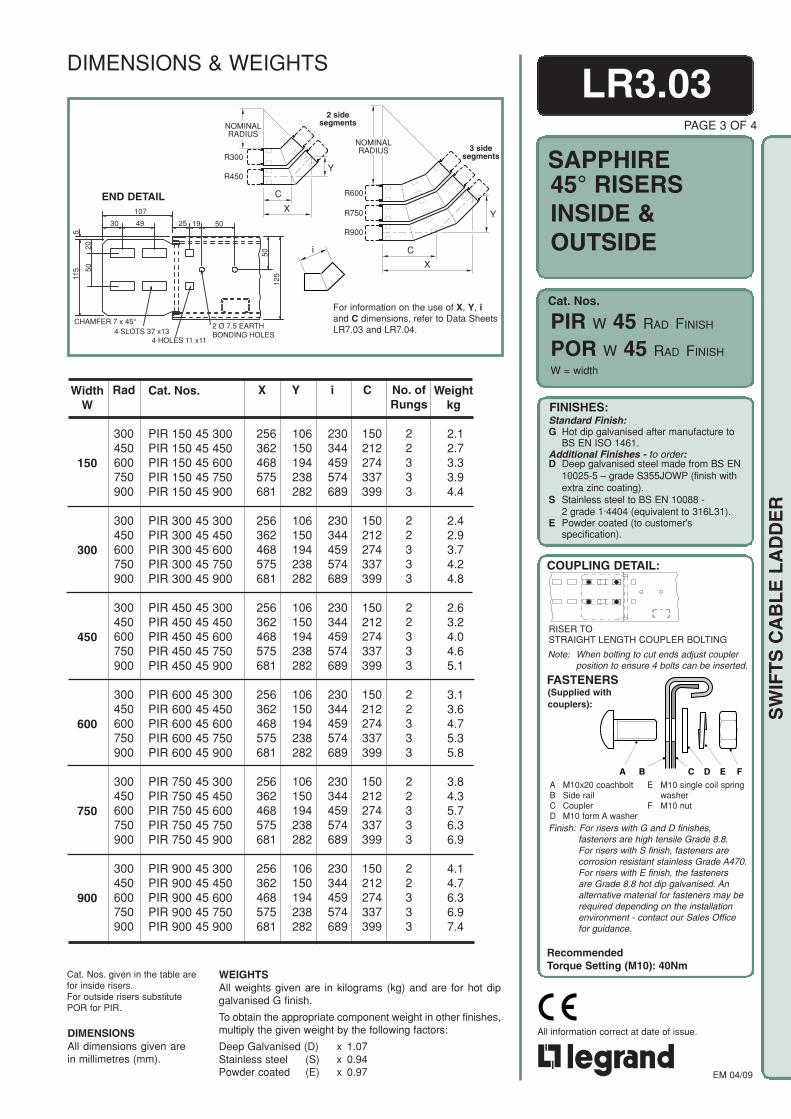
Cat. Nos.
SAPPHIRE
FINISHES:Standard Finish:G Hot dip galvanised after manufacture to
BS EN ISO 1461.Additional Finishes - to order:D Deep galvanised steel made from BS EN
10025-5 – grade S355JOWP (finish withextra zinc coating).
S Stainless steel to BS EN 10088 -2 grade 1·4404 (equivalent to 316L31).
E Powder coated (to customer'sspecification).
COUPLING DETAIL:
(Supplied withcouplers):
FASTENERS
A M10x20 coachboltB Side railC CouplerD M10 form A washer
E M10 single coil springwasher
F M10 nut
A B C D E F
RecommendedTorque Setting (M10): 40Nm
Note: When bolting to cut ends adjust couplerposition to ensure 4 bolts can be inserted.
EM 04/09
All information correct at date of issue.
SW
IFT
S C
AB
LE
LA
DD
ER
C
R750
R900
Y
R600
NOMINALRADIUS
X
3 sidesegments
YR300
R450
NOMINALRADIUS
C
X
2 sidesegments
i
END DETAIL
For information on the use of X, Y, iand C dimensions, refer to Data SheetsLR7.03 and LR7.04.
LR3.03PAGE 3 OF 4
45° RISERSINSIDE &OUTSIDE
PIR W 45 RAD FINISH
POR W 45 RAD FINISH
W = width
Weightkg
Y
106150194238282
106150194238282
106150194238282
106150194238282
106150194238282
106150194238282
i
230344459574689
230344459574689
230344459574689
230344459574689
230344459574689
230344459574689
C
150212274337399
150212274337399
150212274337399
150212274337399
150212274337399
150212274337399
No. ofRungs
22333
22333
22333
22333
22333
22333
X
256362468575681
256362468575681
256362468575681
256362468575681
256362468575681
256362468575681
Rad
300450600750900
300450600750900
300450600750900
300450600750900
300450600750900
300450600750900
WidthW
150
300
450
600
750
900
Cat. Nos.
PIR 150 45 300PIR 150 45 450PIR 150 45 600PIR 150 45 750PIR 150 45 900
PIR 300 45 300PIR 300 45 450PIR 300 45 600PIR 300 45 750PIR 300 45 900
PIR 450 45 300PIR 450 45 450PIR 450 45 600PIR 450 45 750PIR 450 45 900
PIR 600 45 300PIR 600 45 450PIR 600 45 600PIR 600 45 750PIR 600 45 900
PIR 750 45 300PIR 750 45 450PIR 750 45 600PIR 750 45 750PIR 750 45 900
PIR 900 45 300PIR 900 45 450PIR 900 45 600PIR 900 45 750PIR 900 45 900
DIMENSIONSAll dimensions given arein millimetres (mm).
Cat. Nos. given in the table arefor inside risers.For outside risers substitutePOR for PIR.
WEIGHTSAll weights given are in kilograms (kg) and are for hot dipgalvanised G finish.
To obtain the appropriate component weight in other finishes,multiply the given weight by the following factors:
Deep Galvanised (D) x 1.07Stainless steel (S) x 0.94Powder coated (E) x 0.97
2.12.73.33.94.4
2.42.93.74.24.8
2.63.24.04.65.1
3.13.64.75.35.8
3.84.35.76.36.9
4.14.76.36.97.4
DIMENSIONS & WEIGHTS
107
30 49 25 19 50
511
5
2050
CHAMFER 7 x 45°4 SLOTS 37 x13
4 HOLES 11 x11
2 Ø 7.5 EARTHBONDING HOLES
50
125
RISER TOSTRAIGHT LENGTH COUPLER BOLTING
Finish: For risers with G and D finishes,fasteners are high tensile Grade 8.8.For risers with S finish, fasteners arecorrosion resistant stainless Grade A470.For risers with E finish, the fastenersare Grade 8.8 hot dip galvanised. Analternative material for fasteners may berequired depending on the installationenvironment - contact our Sales Officefor guidance.

Cat. Nos.
SAPPHIRE
FINISHES:Standard Finish:G Hot dip galvanised after manufacture to
BS EN ISO 1461.Additional Finishes - to order:D Deep galvanised steel made from BS EN
10025-5 – grade S355JOWP (finish withextra zinc coating).
S Stainless steel to BS EN 10088 -2 grade 1·4404 (equivalent to 316L31).
E Powder coated (to customer'sspecification).
COUPLING DETAIL:
(Supplied withcouplers):
FASTENERS
A M10x20 coachboltB Side railC CouplerD M10 form A washer
E M10 single coil springwasher
F M10 nut
A B C D E F
RecommendedTorque Setting (M10): 40Nm
Note: When bolting to cut ends adjust couplerposition to ensure 4 bolts can be inserted.
EM 04/09
All information correct at date of issue.
SW
IFT
S C
AB
LE
LA
DD
ER
LR3.03
For information on the use of X, Y, i andC dimensions, refer to Data SheetsLR7.03 and LR7.04.
END DETAIL
R900
R600
R750
CX
Y
R300
R450
NOMINALRADIUS
i
Weightkg
Y
496989
109129
496989
109129
496989
109129
496989
109129
496989
109129
496989
109129
i
155233311388466
155233311388466
155233311388466
155233311388466
155233311388466
155233311388466
C
97137178218258
97137178218258
97137178218258
97137178218258
97137178218258
97137178218258
No. ofRungs
22222
22222
22222
22222
22222
22222
X
181256331406481
181256331406481
181256331406481
181256331406481
181256331406481
181256331406481
Rad
300450600750900
300450600750900
300450600750900
300450600750900
300450600750900
300450600750900
WidthW
150
300
450
600
750
900
Cat. Nos.
PIR 150 30 300PIR 150 30 450PIR 150 30 600PIR 150 30 750PIR 150 30 900
PIR 300 30 300PIR 300 30 450PIR 300 30 600PIR 300 30 750PIR 300 30 900
PIR 450 30 300PIR 450 30 450PIR 450 30 600PIR 450 30 750PIR 450 30 900
PIR 600 30 300PIR 600 30 450PIR 600 30 600PIR 600 30 750PIR 600 30 900
PIR 750 30 300PIR 750 30 450PIR 750 30 600PIR 750 30 750PIR 750 30 900
PIR 900 30 300PIR 900 30 450PIR 900 30 600PIR 900 30 750PIR 900 30 900
DIMENSIONSAll dimensions given arein millimetres (mm).
Cat. Nos. given in the table arefor inside risers. For outsiderisers substitute POR for PIR.
WEIGHTSAll weights given are in kilograms (kg) and are for hot dipgalvanised G finish.
To obtain the appropriate component weight in other finishes,multiply the given weight by the following factors:
Deep Galvanised (D) x 1.07Stainless steel (S) x 0.94Powder coated (E) x 0.97
PAGE 4 OF 4
30° RISERSINSIDE &OUTSIDE
POR W 30 RAD FINISH
PIR W 30 RAD FINISH
W = width
1.62.02.42.83.1
1.92.22.63.03.4
2.12.52.93.23.6
2.62.93.33.74.1
3.33.64.04.44.8
3.64.04.44.85.1
DIMENSIONS & WEIGHTS
107
30 49 25 19 50
511
5
2050
CHAMFER 7 x 45°4 SLOTS 37 x13
4 HOLES 11 x11
2 Ø 7.5 EARTHBONDING HOLES
50
125
RISER TOSTRAIGHT LENGTH COUPLER BOLTING
Finish: For risers with G and D finishes,fasteners are high tensile Grade 8.8.For risers with S finish, fasteners arecorrosion resistant stainless Grade A470.For risers with E finish, the fastenersare Grade 8.8 hot dip galvanised. Analternative material for fasteners may berequired depending on the installationenvironment - contact our Sales Office forguidance.

Cat. Nos.
SAPPHIRESTRAIGHTREDUCERS
FINISHES:Standard Finish:G Hot dip galvanised after manufacture to
BS EN ISO 1461.Additional Finishes - to order:D Deep galvanised steel made from BS EN
10025-5 – grade S355JOWP (finish withextra zinc coating).
S Stainless steel to BS EN 10088 -2 grade 1·4404 (equivalent to 316L31).
E Powder coated (to customer'sspecification).
COUPLING DETAIL:
(Supplied withcouplers):
FASTENERS
A M10x20 coachboltB Side railC CouplerD M10 form A washer
E M10 single coil springwasher
F M10 nut
A B C D E F
RecommendedTorque Setting (M10): 40Nm
Note: When bolting to cut ends adjust couplerposition to ensure 4 bolts can be inserted.
EM 04/09
All information correct at date of issue.
SW
IFT
S C
AB
LE
LA
DD
ER
LR3.04END DETAIL
Weightkg
WidthK
150
150300
150300450
150300450600
150300450600750
450
750
WidthW
300
600
900
Cat. Nos.
PSR 300 150
PSR 450 150PSR 450 300
PSR 600 150PSR 600 300PSR 600 450
PSR 750 150PSR 750 300PSR 750 450PSR 750 600
PSR 900 150PSR 900 300PSR 900 450PSR 900 600PSR 900 750
PAGE 1 OF 2
WEIGHTSAll weights given are in kilograms (kg) and are for hot dipgalvanised G finish.
To obtain the appropriate component weight in other finishes,multiply the given weight by the following factors:
Deep Galvanised (D) x 1.07Stainless steel (S) x 0.94Powder coated (E) x 0.97
DIMENSIONSAll dimensions given are in millimetres (mm).
Length
450
450450
500450450
500500450450
550500500450450
3.0
3.43.2
4.13.73.6
4.74.54.24.2
5.35.04.84.64.7
W= main run width,K= reduced run width
PSR W K FINISH
DIMENSIONS & WEIGHTS
107
30 49 25 19 50
511
5
2050
CHAMFER 7 x 45°4 SLOTS 37 x13
4 HOLES 11 x11
2 Ø 7.5 EARTHBONDING HOLES
50
125
REDUCER TOSTRAIGHT LENGTH COUPLER BOLTING
Finish: For reducers with G and D finishes,fasteners are high tensile Grade 8.8. Forreducers with S finish, fasteners arecorrosion resistant stainless Grade A470.For reducers with E finish, the fastenersare Grade 8.8 hot dip galvanised. Analternative material for fasteners may berequired depending on the installationenvironment - contact our Sales Officefor guidance.
WIDTHW
WIDTHK
200
LENGTH
20°
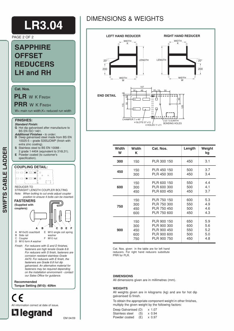
Cat. Nos.
SAPPHIREOFFSETREDUCERSLH and RH
FINISHES:Standard Finish:G Hot dip galvanised after manufacture to
BS EN ISO 1461.Additional Finishes - to order:D Deep galvanised steel made from BS EN
10025-5 – grade S355JOWP (finish withextra zinc coating).
S Stainless steel to BS EN 10088 -2 grade 1·4404 (equivalent to 316L31).
E Powder coated (to customer'sspecification).
COUPLING DETAIL:
(Supplied withcouplers):
FASTENERS
A M10x20 coachboltB Side railC CouplerD M10 form A washer
E M10 single coil springwasher
F M10 nut
A B C D E F
RecommendedTorque Setting (M10): 40Nm
Note: When bolting to cut ends adjust couplerposition to ensure 4 bolts can be inserted.
EM 04/09
All information correct at date of issue.
SW
IFT
S C
AB
LE
LA
DD
ER
END DETAIL
Weightkg
WidthK
150
150300
150300450
150300450600
150300450600750
450
750
WidthW
300
600
900
Cat. Nos.
PLR 300 150
PLR 450 150PLR 450 300
PLR 600 150PLR 600 300PLR 600 450
PLR 750 150PLR 750 300PLR 750 450PLR 750 600
PLR 900 150PLR 900 300PLR 900 450PLR 900 600PLR 900 750
Length
450
500450
550500450
600550500450
650600550500450
3.1
3.73.4
4.44.13.7
5.34.94.64.3
5.95.65.25.04.8
Cat. Nos. given in the table are for left handreducers. For right hand reducers substitutePRR for PLR.
WEIGHTSAll weights given are in kilograms (kg) and are for hot dipgalvanised G finish.
To obtain the appropriate component weight in other finishes,multiply the given weight by the following factors:
Deep Galvanised (D) x 1.07Stainless steel (S) x 0.94Powder coated (E) x 0.97
DIMENSIONSAll dimensions given are in millimetres (mm).
LR3.04PAGE 2 OF 2
W= main run width,K= reduced run width
PLR W K FINISH
PRR W K FINISH
DIMENSIONS & WEIGHTS
107
30 49 25 19 50
511
5
2050
CHAMFER 7 x 45°4 SLOTS 37 x13
4 HOLES 11 x11
2 Ø 7.5 EARTHBONDING HOLES
50
125
REDUCER TOSTRAIGHT LENGTH COUPLER BOLTING
Finish: For reducers with G and D finishes,fasteners are high tensile Grade 8.8.For reducers with S finish, fasteners arecorrosion resistant stainless GradeA470. For reducers with E finish, thefasteners are Grade 8.8 hot dipgalvanised. An alternative material forfasteners may be required dependingon the installation environment - contactour Sales Office for guidance.
WIDTHK
WIDTHW
LEFT HAND REDUCER
LENGTH
200
20°
WIDTHK
WIDTHW
RIGHT HAND REDUCER
LENGTH
200
20°
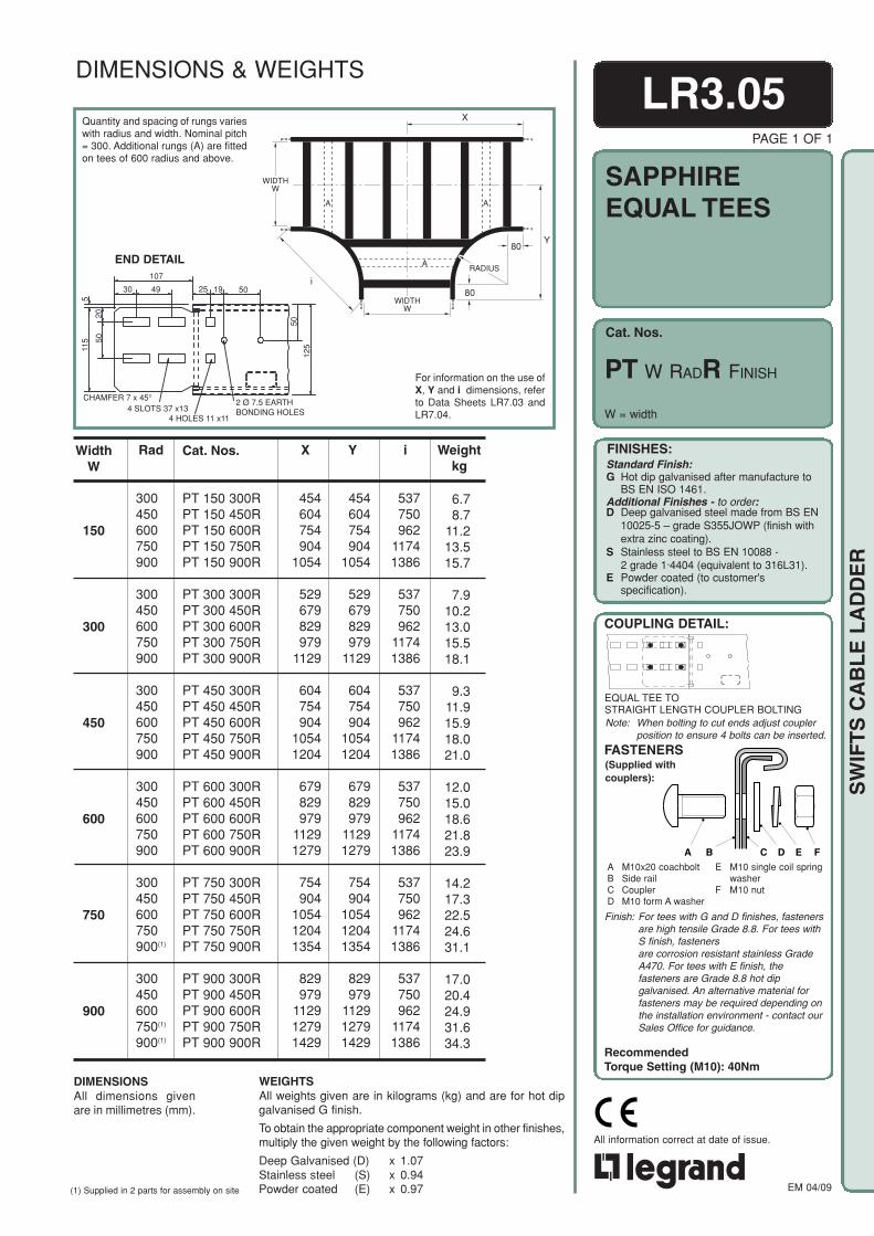
Cat. Nos.
SAPPHIREEQUAL TEES
FINISHES:Standard Finish:G Hot dip galvanised after manufacture to
BS EN ISO 1461.Additional Finishes - to order:D Deep galvanised steel made from BS EN
10025-5 – grade S355JOWP (finish withextra zinc coating).
S Stainless steel to BS EN 10088 -2 grade 1·4404 (equivalent to 316L31).
E Powder coated (to customer'sspecification).
COUPLING DETAIL:
(Supplied withcouplers):
FASTENERS
A M10x20 coachboltB Side railC CouplerD M10 form A washer
E M10 single coil springwasher
F M10 nut
A B C D E F
RecommendedTorque Setting (M10): 40Nm
Note: When bolting to cut ends adjust couplerposition to ensure 4 bolts can be inserted.
EM 04/09
All information correct at date of issue.
SW
IFT
S C
AB
LE
LA
DD
ER
Y80
80
RADIUS
i
WIDTHW
WIDTHW
X
A A
AEND DETAIL
Quantity and spacing of rungs varieswith radius and width. Nominal pitch= 300. Additional rungs (A) are fittedon tees of 600 radius and above.
For information on the use ofX, Y and i dimensions, referto Data Sheets LR7.03 andLR7.04.
LR3.05PAGE 1 OF 1
Weightkg
Rad
300450600750900
300450600750900
300450600750900
300450600750900
300450600750900(1)
300450600750(1)
900(1)
Y
454604754904
1054
529679829979
1129
604754904
10541204
679829979
11291279
754904
105412041354
829979
112912791429
X
454604754904
1054
529679829979
1129
604754904
10541204
679829979
11291279
754904
105412041354
829979
112912791429
i
537750962
11741386
537750962
11741386
537750962
11741386
537750962
11741386
537750962
11741386
537750962
11741386
WidthW
150
300
450
600
750
900
WEIGHTSAll weights given are in kilograms (kg) and are for hot dipgalvanised G finish.
To obtain the appropriate component weight in other finishes,multiply the given weight by the following factors:
Deep Galvanised (D) x 1.07Stainless steel (S) x 0.94Powder coated (E) x 0.97
DIMENSIONSAll dimensions givenare in millimetres (mm).
PT W RADR FINISH
W = width
6.78.7
11.213.515.7
7.910.213.015.518.1
9.311.915.918.021.0
12.015.018.621.823.9
14.217.322.524.631.1
17.020.424.931.634.3
Cat. Nos.
PT 150 300RPT 150 450RPT 150 600RPT 150 750RPT 150 900R
PT 300 300RPT 300 450RPT 300 600RPT 300 750RPT 300 900R
PT 450 300RPT 450 450RPT 450 600RPT 450 750RPT 450 900R
PT 600 300RPT 600 450RPT 600 600RPT 600 750RPT 600 900R
PT 750 300RPT 750 450RPT 750 600RPT 750 750RPT 750 900R
PT 900 300RPT 900 450RPT 900 600RPT 900 750RPT 900 900R
DIMENSIONS & WEIGHTS
107
30 49 25 19 50
511
5
2050
CHAMFER 7 x 45°4 SLOTS 37 x13
4 HOLES 11 x11
2 Ø 7.5 EARTHBONDING HOLES
50
125
EQUAL TEE TOSTRAIGHT LENGTH COUPLER BOLTING
Finish: For tees with G and D finishes, fastenersare high tensile Grade 8.8. For tees withS finish, fastenersare corrosion resistant stainless GradeA470. For tees with E finish, thefasteners are Grade 8.8 hot dipgalvanised. An alternative material forfasteners may be required depending onthe installation environment - contact ourSales Office for guidance.
(1) Supplied in 2 parts for assembly on site

Cat. Nos.
SAPPHIREUNEQUALTEES
FINISHES:Standard Finish:G Hot dip galvanised after manufacture to
BS EN ISO 1461.Additional Finishes - to order:D Deep galvanised steel made from BS EN
10025-5 – grade S355JOWP (finish withextra zinc coating).
S Stainless steel to BS EN 10088 -2 grade 1·4404 (equivalent to 316L31).
E Powder coated (to customer'sspecification).
COUPLING DETAIL:
(Supplied withcouplers):
FASTENERS
A M10x20 coachboltB Side railC CouplerD M10 form A washer
E M10 single coil springwasher
F M10 nut
A B C D E F
RecommendedTorque Setting (M10): 40Nm
Note: When bolting to cut ends adjust couplerposition to ensure 4 bolts can be inserted.
EM 04/09
All information correct at date of issue.
SW
IFT
S C
AB
LE
LA
DD
ER
Weightkg
Y
453603753903
1053
453603753903
1053
453603753903
1053
453603753903
1053
453603753903
1053
X
528678828978
1128
603753903
10531203
678828978
11281278
753903
105312031353
828978
112812781428
WidthB
300
450
600
750
900
i
537750962
11741386
537750962
11741386
537750962
11741386
537750962
11741386
537750962
11741386
WidthW
150
7.49.6
12.114.416.8
8.210.413.215.317.6
9.111.314.316.718.7
10.012.215.617.720.1
10.913.216.518.921.0
Quantity and spacing of rungs varies withradius and width, nominal pitch = 300.
Additional rungs (A) are fitted on tees of600 radius and above.
For information on the use of X, Y, and idimensions, refer to Data Sheets LR7.03and LR7.04.
END DETAIL
WEIGHTSAll weights given are in kilograms (kg) and are for hot dipgalvanised G finish.
To obtain the appropriate component weight in other finishes,multiply the given weight by the following factors:
Deep Galvanised (D) x 1.07Stainless steel (S) x 0.94Powder coated (E) x 0.97
DIMENSIONSAll dimensions given arein millimetres (mm).
LR3.06PAGE 1 OF 4
Rad
300450600750900
300450600750900
300450600750900
300450600750900
300450600750900
Cat. Nos.
PUT 150 300 300RPUT 150 300 450RPUT 150 300 600RPUT 150 300 750RPUT 150 300 900R
PUT 150 450 300RPUT 150 450 450RPUT 150 450 600RPUT 150 450 750RPUT 150 450 900R
PUT 150 600 300RPUT 150 600 450RPUT 150 600 600RPUT 150 600 750RPUT 150 600 900R
PUT 150 750 300RPUT 150 750 450RPUT 150 750 600RPUT 150 750 750RPUT 150 750 900R
PUT 150 900 300RPUT 150 900 450RPUT 150 900 600RPUT 150 900 750RPUT 150 900 900R
PUT 150 B RADR FINISH
DIMENSIONS & WEIGHTS
107
30 49 25 19 50
511
5
2050
CHAMFER 7 x 45°4 SLOTS 37 x13
4 HOLES 11 x11
2 Ø 7.5 EARTHBONDING HOLES
50
125
B = branch width
UNEQUAL TEE TOSTRAIGHT LENGTH COUPLER BOLTING
Finish: For tees with G and D finishes, fastenersare high tensile Grade 8.8. For tees withS finish, fastenersare corrosion resistant stainless GradeA470. For tees with E finish, thefasteners are Grade 8.8 hot dipgalvanised. An alternative material forfasteners may be required depending onthe installation environment - contact ourSales Office for guidance.
Y
80
80RADIUS
i
X
A
A
A
WIDTHW
WIDTHB

Cat. Nos.
SAPPHIREUNEQUALTEES
FINISHES:Standard Finish:G Hot dip galvanised after manufacture to
BS EN ISO 1461.Additional Finishes - to order:D Deep galvanised steel made from BS EN
10025-5 – grade S355JOWP (finish withextra zinc coating).
S Stainless steel to BS EN 10088 -2 grade 1·4404 (equivalent to 316L31).
E Powder coated (to customer'sspecification).
COUPLING DETAIL:
(Supplied withcouplers):
FASTENERS
A M10x20 coachboltB Side railC CouplerD M10 form A washer
E M10 single coil springwasher
F M10 nut
A B C D E F
RecommendedTorque Setting (M10): 40Nm
Note: When bolting to cut ends adjust couplerposition to ensure 4 bolts can be inserted.
EM 04/09
All information correct at date of issue.
SW
IFT
S C
AB
LE
LA
DD
ER
Weightkg
WidthW
300
450
Y
528678828978
1128
528678828978
1128
528678828978
1128
528678828978
1128
528678828978
1128
603753903
10531203
603753903
10531203
603753903
10531203
603753903
10531203
603753903
10531203
X
453603753903
1053
603753903
10531203
678828978
11281278
753903
105312031353
828978
112812781428
453603753903
1053
528678828978
1128
678828978
11281278
753903
105312031353
828978
112812781428
WidthB
150
450
600
750
900
150
300
600
750
900
Rad
300450600750900
300450600750900
300450600750900
300450600750900
300450600750900
300450600750900
300450600750900
300450600750900
300450600750900
300450600750900
i
537750962
11741386
537750962
11741386
537750962
11741386
537750962
11741386
537750962
11741386
537750962
11741386
537750962
11741386
537750962
11741386
537750962
11741386
537750962
11741386
7.29.1
12.114.616.8
8.711.014.316.419.0
9.712.115.418.020.1
10.613.016.919.021.7
11.614.017.820.422.6
7.99.8
13.416.218.5
8.611.114.317.120.1
10.613.217.019.922.1
11.514.118.821.024.0
12.715.419.722.724.9
LR3.06PAGE 2 OF 4
B = branch width
WEIGHTSAll weights given are in kilograms (kg) and are for hot dipgalvanised G finish.
To obtain the appropriate component weight in other finishes,multiply the given weight by the following factors:
Deep Galvanised (D) x 1.07Stainless steel (S) x 0.94Powder coated (E) x 0.97
DIMENSIONSAll dimensions given arein millimetres (mm).
PUT 300 B RADR FINISH
PUT 450 B RADR FINISH
Cat. Nos.
PUT 300 150 300RPUT 300 150 450RPUT 300 150 600RPUT 300 150 750RPUT 300 150 900R
PUT 300 450 300RPUT 300 450 450RPUT 300 450 600RPUT 300 450 750RPUT 300 450 900R
PUT 300 600 300RPUT 300 600 450RPUT 300 600 600RPUT 300 600 750RPUT 300 600 900R
PUT 300 750 300RPUT 300 750 450RPUT 300 750 600RPUT 300 750 750RPUT 300 750 900R
PUT 300 900 300RPUT 300 900 450RPUT 300 900 600RPUT 300 900 750RPUT 300 900 900R
PUT 450 150 300RPUT 450 150 450RPUT 450 150 600RPUT 450 150 750RPUT 450 150 900R
PUT 450 300 300RPUT 450 300 450RPUT 450 300 600RPUT 450 300 750RPUT 450 300 900R
PUT 450 600 300RPUT 450 600 450RPUT 450 600 600RPUT 450 600 750RPUT 450 600 900R
PUT 450 750 300RPUT 450 750 450RPUT 450 750 600RPUT 450 750 750RPUT 450 750 900R
PUT 450 900 300RPUT 450 900 450RPUT 450 900 600RPUT 450 900 750RPUT 450 900 900R
DIMENSIONS & WEIGHTS
UNEQUAL TEE TOSTRAIGHT LENGTH COUPLER BOLTING
Finish: For tees with G and D finishes,fasteners are high tensile Grade 8.8.For tees with S finish, fastenersare corrosion resistant stainlessGrade A470. For tees with E finish,the fasteners are Grade 8.8 hot dipgalvanised. An alternative materialfor fasteners may be requireddepending on the installationenvironment - contact our SalesOffice for guidance.

Cat. Nos.
SAPPHIREUNEQUALTEES
FINISHES:Standard Finish:G Hot dip galvanised after manufacture to
BS EN ISO 1461.Additional Finishes - to order:D Deep galvanised steel made from BS EN
10025-5 – grade S355JOWP (finish withextra zinc coating).
S Stainless steel to BS EN 10088 -2 grade 1·4404 (equivalent to 316L31).
E Powder coated (to customer'sspecification).
COUPLING DETAIL:
(Supplied withcouplers):
FASTENERS
A M10x20 coachboltB Side railC CouplerD M10 form A washer
E M10 single coil springwasher
F M10 nut
A B C D E F
RecommendedTorque Setting (M10): 40Nm
Note: When bolting to cut ends adjust couplerposition to ensure 4 bolts can be inserted.
EM 04/09
All information correct at date of issue.
SW
IFT
S C
AB
LE
LA
DD
ER
END DETAIL
Weightkg
WidthB
150
300
450
750
900
Y
678828978
11281278
678828978
11281278
678828978
11281278
678828978
11281278
678828978
11281278
X
453603753903
1053
528678828978
1128
603753903
10531203
753903
105312031353
828978
112812781428
Rad
300450600750900
300450600750900
300450600750900
300450600750900
300450600750900
i
537750962
11741386
537750962
11741386
537750962
11741386
537750962
11741386
537750962
11741386
WidthW
600
9.011.014.817.820.1
9.712.515.718.821.9
10.413.317.519.722.8
12.915.920.622.826.1
14.517.521.624.727.0
WEIGHTSAll weights given are in kilograms (kg) and are for hot dipgalvanised G finish.
To obtain the appropriate component weight in other finishes,multiply the given weight by the following factors:
Deep Galvanised (D) x 1.07Stainless steel (S) x 0.94Powder coated (E) x 0.97
DIMENSIONSAll dimensions given arein millimetres (mm).
PAGE 3 OF 4
LR3.06
B = branch width
Cat. Nos.
PUT 600 150 300RPUT 600 150 450RPUT 600 150 600RPUT 600 150 750RPUT 600 150 900R
PUT 600 300 300RPUT 600 300 450RPUT 600 300 600RPUT 600 300 750RPUT 600 300 900R
PUT 600 450 300RPUT 600 450 450RPUT 600 450 600RPUT 600 450 750RPUT 600 450 900R
PUT 600 750 300RPUT 600 750 450RPUT 600 750 600RPUT 600 750 750RPUT 600 750 900R
PUT 600 900 300RPUT 600 900 450RPUT 600 900 600RPUT 600 900 750RPUT 600 900 900R
PUT 600 B RADR FINISH
DIMENSIONS & WEIGHTS
107
30 49 25 19 50
511
5
2050
CHAMFER 7 x 45°4 SLOTS 37 x13
4 HOLES 11 x11
2 Ø 7.5 EARTHBONDING HOLES
50
125
UNEQUAL TEE TOSTRAIGHT LENGTH COUPLER BOLTING
Finish: For tees with G and D finishes,fasteners are high tensile Grade 8.8.For tees with S finish, fastenersare corrosion resistant stainlessGrade A470. For tees with E finish,the fasteners are Grade 8.8 hot dipgalvanised. An alternative materialfor fasteners may be requireddepending on the installationenvironment - contact our SalesOffice for guidance.
Y
80
80RADIUS
i
X
A
A
A
WIDTHW
WIDTHB
Quantity and spacing of rungs varies withradius and width, nominal pitch = 300.
Additional rungs (A) are fitted on tees of 600radius and above.
For information on the use of X, Y, and idimensions, refer to Data Sheets LR7.03and LR7.04.

Cat. Nos.
SAPPHIREUNEQUALTEES
FINISHES:Standard Finish:G Hot dip galvanised after manufacture to
BS EN ISO 1461.Additional Finishes - to order:D Deep galvanised steel made from BS EN
10025-5 – grade S355JOWP (finish withextra zinc coating).
S Stainless steel to BS EN 10088 -2 grade 1·4404 (equivalent to 316L31).
E Powder coated (to customer'sspecification).
COUPLING DETAIL:
(Supplied withcouplers):
FASTENERS
A M10x20 coachboltB Side railC CouplerD M10 form A washer
E M10 single coil springwasher
F M10 nut
A B C D E F
RecommendedTorque Setting (M10): 40Nm
Note: When bolting to cut ends adjust couplerposition to ensure 4 bolts can be inserted.
EM 04/09
All information correct at date of issue.
SW
IFT
S C
AB
LE
LA
DD
ER
LR3.06PAGE 4 OF 4
B = branch width
(For illustration see previous page).
Weightkg
Y
753903
105312031353
753903
105312031353
753903
105312031353
753903
105312031353
753903
105312031353
828978
112812781428
828978
112812781428
828978
112812781428
828978
112812781428
828978
112812781428
X
453603753903
1053
528678828978
1128
603753903
10531203
678828978
11281278
828978
112812781428
453603753903
1053
528678828978
1128
603753903
10531203
678828978
11281278
753903
105312031353
WidthB
150
300
450
600
900
150
300
450
600
750
Rad
300450600750900(1)
300450600750900(1)
300450600750900(1)
300450600750900(1)
300450600750900(1)
300450600750(1)
900(1)
300450600750(1)
900(1)
300450600750(1)
900(1)
300450600750(1)
900(1)
300450600750(1)
900(1)
i
537750962
11741386
537750962
11741386
537750962
11741386
537750962
11741386
537750962
11741386
537750962
11741386
537750962
11741386
537750962
11741386
537750962
11741386
537750962
11741386
WidthW
750
900
WEIGHTSAll weights given are in kilograms (kg) and are for hot dipgalvanised G finish.
To obtain the appropriate component weight in other finishes,multiply the given weight by the following factors:
Deep Galvanised (D) x 1.07Stainless steel (S) x 0.94Powder coated (E) x 0.97
DIMENSIONSAll dimensions givenare in millimetres (mm).
10.012.016.319.525.5
10.713.817.220.426.2
11.514.619.221.329.4
13.316.420.323.630.3
15.919.123.426.732.3
10.812.817.424.627.2
11.514.718.325.327.9
12.215.520.526.131.4
14.217.521.629.732.3
15.118.424.030.433.1
PUT 750 B RADR FINISH
PUT 900 B RADR FINISH
Cat. Nos.
PUT 750 150 300RPUT 750 150 450RPUT 750 150 600RPUT 750 150 750RPUT 750 150 900R
PUT 750 300 300RPUT 750 300 450RPUT 750 300 600RPUT 750 300 750RPUT 750 300 900R
PUT 750 450 300RPUT 750 450 450RPUT 750 450 600RPUT 750 450 750RPUT 750 450 900R
PUT 750 600 300RPUT 750 600 450RPUT 750 600 600RPUT 750 600 750RPUT 750 600 900R
PUT 750 900 300RPUT 750 900 450RPUT 750 900 600RPUT 750 900 750RPUT 750 900 900R
PUT 900 150 300RPUT 900 150 450RPUT 900 150 600RPUT 900 150 750RPUT 900 150 900R
PUT 900 300 300RPUT 900 300 450RPUT 900 300 600RPUT 900 300 750RPUT 900 300 900R
PUT 900 450 300RPUT 900 450 450RPUT 900 450 600RPUT 900 450 750RPUT 900 450 900R
PUT 900 600 300RPUT 900 600 450RPUT 900 600 600RPUT 900 600 750RPUT 900 600 900R
PUT 900 750 300RPUT 900 750 450RPUT 900 750 600RPUT 900 750 750RPUT 900 750 900R
DIMENSIONS & WEIGHTS
UNEQUAL TEE TOSTRAIGHT LENGTH COUPLER BOLTING
Finish: For tees with G and D finishes,fasteners are high tensile Grade 8.8. Fortees with S finish, fastenersare corrosion resistant stainless GradeA470. For tees with E finish, thefasteners are Grade 8.8 hot dipgalvanised. An alternative material forfasteners may be required depending onthe installation environment - contact ourSales Office for guidance.
(1) Supplied in 2 parts for assembly on site
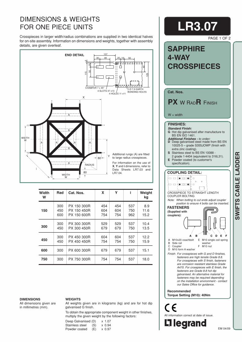
Cat. Nos.
SAPPHIRE4-WAYCROSSPIECES
FINISHES:Standard Finish:G Hot dip galvanised after manufacture to
BS EN ISO 1461.Additional Finishes - to order:D Deep galvanised steel made from BS EN
10025-5 – grade S355JOWP (finish withextra zinc coating).
S Stainless steel to BS EN 10088 -2 grade 1·4404 (equivalent to 316L31).
E Powder coated (to customer'sspecification).
COUPLING DETAIL:
(Supplied withcouplers):
FASTENERS
A M10x20 coachboltB Side railC CouplerD M10 form A washer
E M10 single coil springwasher
F M10 nut
A B C D E F
RecommendedTorque Setting (M10): 40Nm
Note: When bolting to cut ends adjust couplerposition to ensure 4 bolts can be inserted.
EM 04/09
All information correct at date of issue.
SW
IFT
S C
AB
LE
LA
DD
ER
Crosspieces in larger width/radius combinations are supplied in two identical halvesfor on-site assembly. Information on dimensions and weights, together with assemblydetails, are given overleaf.
Y80
80
RADIUS
i
WIDTHW
WIDTHW
X
A A
A
A
A A
A
A
END DETAIL
Additional rungs (A) are fittedto large radius crosspieces.
For information on the use ofX, Y and i dimensions, refer toData Sheets LR7.03 andLR7.04.
Weightkg
i
537750962
537750
537750
537
537
Rad
300450600
300450
300450
300
300
Y
454604754
529679
604754
679
754
X
454604754
529679
604754
679
754
WidthW
150
300
450
600
750
WEIGHTSAll weights given are in kilograms (kg) and are for hot dipgalvanised G finish.
To obtain the appropriate component weight in other finishes,multiply the given weight by the following factors:
Deep Galvanised (D) x 1.07Stainless steel (S) x 0.94Powder coated (E) x 0.97
DIMENSIONSAll dimensions given arein millimetres (mm).
LR3.07PAGE 1 OF 2
W = width
8.911.615.2
10.413.5
12.215.9
15.1
18.0
Cat. Nos.
PX 150 300RPX 150 450RPX 150 600R
PX 300 300RPX 300 450R
PX 450 300RPX 450 450R
PX 600 300R
PX 750 300R
PX W RADR FINISH
DIMENSIONS & WEIGHTSFOR ONE PIECE UNITS
107
30 49 25 19 50
511
5
2050
CHAMFER 7 x 45°4 SLOTS 37 x13
4 HOLES 11 x11
2 Ø 7.5 EARTHBONDING HOLES
50
125
CROSSPIECE TO STRAIGHT LENGTHCOUPLER BOLTING
Finish: For crosspieces with G and D finishes,fasteners are high tensile Grade 8.8.For crosspieces with S finish, fastenersare corrosion resistant stainless GradeA470. For crosspieces with E finish, thefasteners are Grade 8.8 hot dipgalvanised. An alternative material forfasteners may be required dependingon the installation environment - contactour Sales Office for guidance.
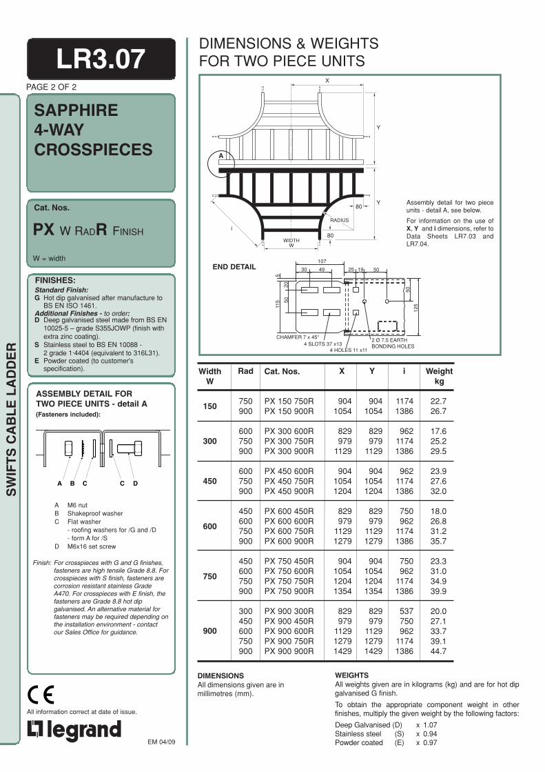
Cat. Nos.
SAPPHIRE4-WAYCROSSPIECES
FINISHES:Standard Finish:G Hot dip galvanised after manufacture to
BS EN ISO 1461.Additional Finishes - to order:D Deep galvanised steel made from BS EN
10025-5 – grade S355JOWP (finish withextra zinc coating).
S Stainless steel to BS EN 10088 -2 grade 1·4404 (equivalent to 316L31).
E Powder coated (to customer'sspecification).
COUPLING DETAIL:
(Supplied withcouplers):
FASTENERS
A M10x20 coachboltB Side railC CouplerD M10 form A washer
RecommendedTorque Setting (M10): 40Nm
Also refer toData SheetLR6.01.
Note: When bolting to cut ends adjust couplerposition to ensure 8 bolts can be
EM 04/09
All information correct at date of issue.
SW
IFT
S C
AB
LE
LA
DD
ER
LR3.07PAGE 2 OF 2
80
80
RADIUS
i
WIDTHW
X
Y
A
Y
For information on the use ofX, Y and i dimensions, refer toData Sheets LR7.03 andLR7.04.
Assembly detail for two pieceunits - detail A, see below.
END DETAIL
WEIGHTSAll weights given are in kilograms (kg) and are for hot dipgalvanised G finish.
To obtain the appropriate component weight in otherfinishes, multiply the given weight by the following factors:
Deep Galvanised (D) x 1.07Stainless steel (S) x 0.94Powder coated (E) x 0.97
DIMENSIONSAll dimensions given are inmillimetres (mm).
W = width
PX W RADR FINISH
DIMENSIONS & WEIGHTSFOR TWO PIECE UNITS
107
30 49 25 19 505
115
2050
CHAMFER 7 x 45°4 SLOTS 37 x13
4 HOLES 11 x11
2 Ø 7.5 EARTHBONDING HOLES
50
125
ASSEMBLY DETAIL FORTWO PIECE UNITS - detail A(Fasteners included):
A B C DC
A M6 nutB Shakeproof washerC Flat washer
- roofing washers for /G and /D- form A for /S
D M6x16 set screw
Finish: For crosspieces with G and G finishes,fasteners are high tensile Grade 8.8. Forcrosspieces with S finish, fasteners arecorrosion resistant stainless GradeA470. For crosspieces with E finish, thefasteners are Grade 8.8 hot dipgalvanised. An alternative material forfasteners may be required depending onthe installation environment - contactour Sales Office for guidance.
Weightkg
i
11741386
96211741386
96211741386
750962
11741386
750962
11741386
537750962
11741386
Rad
750900
600750900
600750900
450600750900
450600750900
300450600750900
Y
9041054
829979
1129
90410541204
829979
11291279
904105412041354
829979
112912791429
X
9041054
829979
1129
90410541204
829979
11291279
904105412041354
829979
112912791429
WidthW
150
300
450
600
750
900
22.726.7
17.625.229.5
23.927.632.0
18.026.831.235.7
23.331.034.939.9
20.027.133.739.144.7
Cat. Nos.
PX 150 750RPX 150 900R
PX 300 600RPX 300 750RPX 300 900R
PX 450 600RPX 450 750RPX 450 900R
PX 600 450RPX 600 600RPX 600 750RPX 600 900R
PX 750 450RPX 750 600RPX 750 750RPX 750 900R
PX 900 300RPX 900 450RPX 900 600RPX 900 750RPX 900 900R

Note: When bolting to cut ends adjust couplerposition to ensure 8 bolts can be inserted.
Cat. Nos.
EMERALD
RecommendedTorque Setting (M10): 40Nm
FINISHES:Standard Finish:G Hot dip galvanised after manufacture to
BS EN ISO 1461.Additional Finishes - to order:D Deep galvanised steel made from BS EN
10025-5 – grade S355JOWP (finish withextra zinc coating).
S Stainless steel to BS EN 10088 -2 grade 1·4404 (equivalent to 316L31).
E Powder coated (to customer'sspecification).
COUPLING DETAIL:Also refer toData SheetLR6.01.
A M10x20 coachboltB Side railC CouplerD M10 form A washer
E M10 single coil springwasherF M10 nut
FASTENERS(Supplied withcouplers):
EM 04/09
All information correct at date of issue.
SW
IFT
S C
AB
LE
LA
DD
ER
ACTUALSIZE
Type 1 rungs are used as standard. Fordetails of these, and other available rungoptions, refer to Data Sheet LR7.01.
LR4.01PAGE 1 OF 1
W = width
For cable load capacitysee loading graphs.
STRAIGHTLENGTHS
EL W FINISH 6mEL W FINISH
DIMENSIONSAll dimensions given are inmillimetres (mm).
WEIGHTSAll weights given are in kilograms(kg) and are for a 3m straightlength in a hot dip galvanised Gfinish.
To obtain the appropriatecomponent weight in otherfinishes, multiply the given weightby the following factors:
Deep Galvanised (D) x 1.07Stainless steel (S) x 0.97Powder coated (E) x 0.97
Weightkg
WidthW
150
300
450
600
750
900
20.7
22.1
23.5
25.0
28.8
30.8
Cat. Nos.
EL 150
EL 300
EL 450
EL 600
EL 750
EL 900
DIMENSIONS & WEIGHTS
STRAIGHT LENGTH TOSTRAIGHT LENGTH COUPLER BOLTING
Finish: For ladders with G and D finishes,fasteners are high tensile Grade 8.8.For ladders with S finish, fastenersare corrosion resistant stainless GradeA470. For ladders with E finish, thefasteners are Grade 8.8 hot dipgalvanised. An alternative material forfasteners may be required dependingon the installation environment - contactour Sales Office for guidance.
A B C D E F
3000 or 6000
150 300RUNGPITCH
37.519W - 4
W + 40
22
37.5
502.0THICK
119150
INTERNAL WIDTH
Ø7.5 DRAIN HOLESAT 300 CENTRES
22 x 11 BOLT SLOTSAT 37.5 PITCH
Ø7.5 EARTHBONDING HOLESAT 75 PITCH
TYPE 1 RUNG

Note: When bolting to cut ends adjust couplerposition to ensure 4 bolts can be inserted.
Cat. Nos.
EMERALD
RecommendedTorque Setting (M10): 40Nm
FINISHES:Standard Finish:G Hot dip galvanised after manufacture to
BS EN ISO 1461.Additional Finishes - to order:D Deep galvanised steel made from BS EN
10025-5 – grade S355JOWP (finish withextra zinc coating).
S Stainless steel to BS EN 10088 -2 grade 1·4404 (equivalent to 316L31).
E Powder coated (to customer'sspecification).
COUPLING DETAIL:
A B C D E F
A M10x20 coachboltB Side railC CouplerD M10 form A washer
E M10 single coil springwasher
F M10 nut
FASTENERS(Supplied withcouplers):
EM 04/09
All information correct at date of issue.
SW
IFT
S C
AB
LE
LA
DD
ER
LR4.02PAGE 1 OF 4
90°FLAT BENDS
X
80
i
80
C
WIDTH
Y
RADIUS
END DETAIL
For information on the use of X, Y, iand C dimensions, refer to DataSheets LR7.03 and LR7.04.
Weightkg
Cat. Nos.
EFB 150 90 300EFB 150 90 450EFB 150 90 600EFB 150 90 750EFB 150 90 900
EFB 300 90 300EFB 300 90 450EFB 300 90 600EFB 300 90 750EFB 300 90 900
EFB 450 90 300EFB 450 90 450EFB 450 90 600EFB 450 90 750EFB 450 90 900
EFB 600 90 300EFB 600 90 450EFB 600 90 600EFB 600 90 750EFB 600 90 900
EFB 750 90 300EFB 750 90 450EFB 750 90 600EFB 750 90 750EFB 750 90 900
EFB 900 90 300EFB 900 90 450EFB 900 90 600EFB 900 90 750EFB 900 90 900
No. ofRungs
33444
33445
34455
44555
45556
55566
Rad
300450600750900
300450600750900
300450600750900
300450600750900
300450600750900
300450600750900
WidthW
150
300
450
600
750
900
453603753903
1053
528678828978
1128
603753903
10531203
678828978
11281278
753903
105312031353
828978
112812781428
453603753903
1053
528678828978
1128
603753903
10531203
678828978
11281278
753903
105312031353
828978
112812781428
453603753903
1053
528678828978
1128
603753903
10531203
678828978
11281278
753903
105312031353
828978
112812781428
537750962
11741386
537750962
11741386
537750962
11741386
537750962
11741386
537750962
11741386
537750962
11741386
X Y i C
DIMENSIONSAll dimensions given arein millimetres (mm).
W = width
EFB W 90 RAD FINISH
WEIGHTSAll weights given are in kilograms (kg) and are for hot dipgalvanised G finish.
To obtain the appropriate component weight in other finishes,multiply the given weight by the following factors:
Deep Galvanised (D) x 1.07Stainless steel (S) x 0.94Powder coated (E) x 0.97
6.38.09.7
11.312.9
7.59.1
11.012.614.5
8.710.712.314.315.9
10.812.414.616.217.8
12.915.517.118.721.3
15.617.218.921.623.2
DIMENSIONS & WEIGHTS
30 49
107
25 19 50
62.5
150
139 50
32
5.5
CHAMFER 7 x 45˚
4 SLOTS 37 x 13 2 HOLES 11 x 112 Ø 7.5 EARTHBONDING HOLES
FLAT BEND TOSTRAIGHT LENGTH COUPLER BOLTING
Finish: For bends with G and D finishes,fasteners are high tensile Grade 8.8.For bends with S finish, fastenersare corrosion resistant stainless GradeA470. For bends with E finish, thefasteners are Grade 8.8 hot dipgalvanised. An alternative material forfasteners may be required dependingon the installation environment - contactour Sales Office for guidance.

Note: When bolting to cut ends adjust couplerposition to ensure 4 bolts can be inserted.
Cat. Nos.
EMERALD
RecommendedTorque Setting (M10): 40Nm
FINISHES:Standard Finish:G Hot dip galvanised after manufacture to
BS EN ISO 1461.Additional Finishes - to order:D Deep galvanised steel made from BS EN
10025-5 – grade S355JOWP (finish withextra zinc coating).
S Stainless steel to BS EN 10088 -2 grade 1·4404 (equivalent to 316L31).
E Powder coated (to customer'sspecification).
COUPLING DETAIL:
A B C D E F
A M10x20 coachboltB Side railC CouplerD M10 form A washer
E M10 single coil springwasher
F M10 nut
FASTENERS(Supplied withcouplers):
EM 04/09
All information correct at date of issue.
END DETAILX
80
i
80RADIUS
C
WIDTH
Y
For information on the use of X, Y, iand C dimensions, refer to DataSheets LR7.03 and LR7.04.
Weightkg
439589739889
1039
439589739889
1039
439589739889
1039
439589739889
1039
439589739889
1039
439589739889
1039
296382469555642
339426512599685
382469555642728
426512599685772
469555642729815
512598685772858
256331406481556
294369444519594
331406481556631
368443518593668
406481556631706
443518593668743
No. ofRungs
23333
33334
33344
33444
34444
44445
Rad
300450600750900
300450600750900
300450600750900
300450600750900
300450600750900
300450600750900
WidthW
150
300
450
600
750
900
CiYX
WEIGHTSAll weights given are in kilograms (kg) and are for hot dipgalvanised G finish.
To obtain the appropriate component weight in other finishes,multiply the given weight by the following factors:
Deep Galvanised (D) x 1.07Stainless steel (S) x 0.94Powder coated (E) x 0.97
DIMENSIONSAll dimensions given arein millimetres (mm).
LR4.02PAGE 2 OF 4
60°FLAT BENDS
Cat. Nos.
EFB 150 60 300EFB 150 60 450EFB 150 60 600EFB 150 60 750EFB 150 60 900
EFB 300 60 300EFB 300 60 450EFB 300 60 600EFB 300 60 750EFB 300 60 900
EFB 450 60 300EFB 450 60 450EFB 450 60 600EFB 450 60 750EFB 450 60 900
EFB 600 60 300EFB 600 60 450EFB 600 60 600EFB 600 60 750EFB 600 60 900
EFB 750 60 300EFB 750 60 450EFB 750 60 600EFB 750 60 750EFB 750 60 900
EFB 900 60 300EFB 900 60 450EFB 900 60 600EFB 900 60 750EFB 900 60 900
4.96.17.18.29.3
5.97.08.09.1
10.4
6.87.98.9
10.411.5
8.09.1
10.811.812.9
9.611.612.713.814.8
11.812.914.015.017.3
443573703833963
508638768898
1028
573703833963
1093
638768898
10281157
703833963
10931222
768898
102811571287
EFB W 60 RAD FINISH
W = width
DIMENSIONS & WEIGHTS
30 49
107
25 19 50
62.5
150
139 50
32
5.5
CHAMFER 7 x 45˚
4 SLOTS 37 x 13 2 HOLES 11 x 112 Ø 7.5 EARTHBONDING HOLES
FLAT BEND TOSTRAIGHT LENGTH COUPLER BOLTING
Finish: For bends with G and D finishes,fasteners are high tensile Grade 8.8.For bends with S finish, fastenersare corrosion resistant stainless GradeA470. For bends with E finish, thefasteners are Grade 8.8 hot dipgalvanised. An alternative material forfasteners may be required dependingon the installation environment - contactour Sales Office for guidance.
SW
IFT
S C
AB
LE
LA
DD
ER
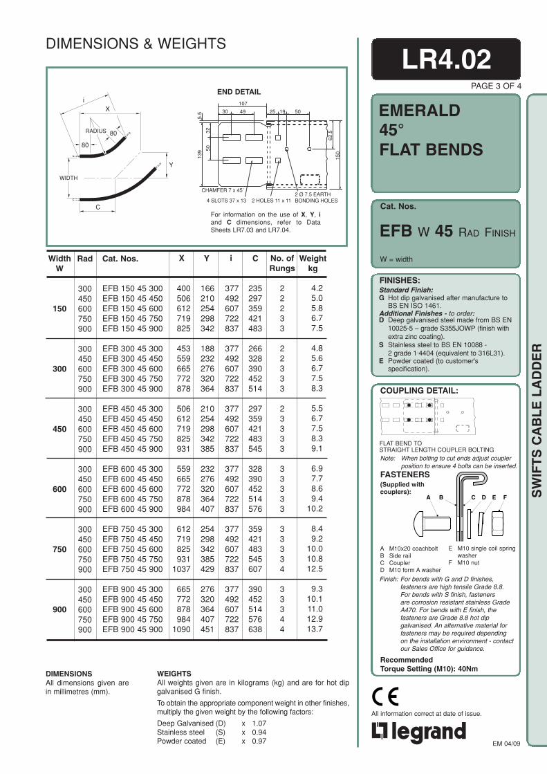
Note: When bolting to cut ends adjust couplerposition to ensure 4 bolts can be inserted.
Cat. Nos.
EMERALD
RecommendedTorque Setting (M10): 40Nm
FINISHES:Standard Finish:G Hot dip galvanised after manufacture to
BS EN ISO 1461.Additional Finishes - to order:D Deep galvanised steel made from BS EN
10025-5 – grade S355JOWP (finish withextra zinc coating).
S Stainless steel to BS EN 10088 -2 grade 1·4404 (equivalent to 316L31).
E Powder coated (to customer'sspecification).
COUPLING DETAIL:
A B C D E F
A M10x20 coachboltB Side railC CouplerD M10 form A washer
E M10 single coil springwasher
F M10 nut
FASTENERS(Supplied withcouplers):
EM 04/09
All information correct at date of issue.
W = width
LR4.02PAGE 3 OF 4
45°FLAT BENDS
X
80
i
80
RADIUS
C
WIDTH
Y
END DETAIL
For information on the use of X, Y, iand C dimensions, refer to DataSheets LR7.03 and LR7.04.
Weightkg
Cat. Nos.
EFB 150 45 300EFB 150 45 450EFB 150 45 600EFB 150 45 750EFB 150 45 900
EFB 300 45 300EFB 300 45 450EFB 300 45 600EFB 300 45 750EFB 300 45 900
EFB 450 45 300EFB 450 45 450EFB 450 45 600EFB 450 45 750EFB 450 45 900
EFB 600 45 300EFB 600 45 450EFB 600 45 600EFB 600 45 750EFB 600 45 900
EFB 750 45 300EFB 750 45 450EFB 750 45 600EFB 750 45 750EFB 750 45 900
EFB 900 45 300EFB 900 45 450EFB 900 45 600EFB 900 45 750EFB 900 45 900
Rad
300450600750900
300450600750900
300450600750900
300450600750900
300450600750900
300450600750900
WidthW
150
300
450
600
750
900
i
377492607722837
377492607722837
377492607722837
377492607722837
377492607722837
377492607722837
4.25.05.86.77.5
4.85.66.77.58.3
5.56.77.58.39.1
6.97.78.69.4
10.2
8.49.2
10.010.812.5
9.310.111.012.913.7
166210254298342
188232276320364
210254298342385
232276320364407
254298342385429
276320364407451
No. ofRungs
22233
22333
23333
33333
33334
33344
400506612719825
453559665772878
506612719825931
559665772878984
612719825931
1037
665772878984
1090
235297359421483
266328390452514
297359421483545
328390452514576
359421483545607
390452514576638
CYX
WEIGHTSAll weights given are in kilograms (kg) and are for hot dipgalvanised G finish.
To obtain the appropriate component weight in other finishes,multiply the given weight by the following factors:
Deep Galvanised (D) x 1.07Stainless steel (S) x 0.94Powder coated (E) x 0.97
DIMENSIONSAll dimensions given arein millimetres (mm).
EFB W 45 RAD FINISH
DIMENSIONS & WEIGHTS
FLAT BEND TOSTRAIGHT LENGTH COUPLER BOLTING
Finish: For bends with G and D finishes,fasteners are high tensile Grade 8.8.For bends with S finish, fastenersare corrosion resistant stainless GradeA470. For bends with E finish, thefasteners are Grade 8.8 hot dipgalvanised. An alternative material forfasteners may be required dependingon the installation environment - contactour Sales Office for guidance.
SW
IFT
S C
AB
LE
LA
DD
ER
30 49
107
25 19 50
62.5
150
139 50
32
5.5
CHAMFER 7 x 45˚
4 SLOTS 37 x 13 2 HOLES 11 x 112 Ø 7.5 EARTHBONDING HOLES

Note: When bolting to cut ends adjust couplerposition to ensure 4 bolts can be inserted.
Cat. Nos.
EMERALD
RecommendedTorque Setting (M10): 40Nm
FINISHES:Standard Finish:G Hot dip galvanised after manufacture to
BS EN ISO 1461.Additional Finishes - to order:D Deep galvanised steel made from BS EN
10025-5 – grade S355JOWP (finish withextra zinc coating).
S Stainless steel to BS EN 10088 -2 grade 1·4404 (equivalent to 316L31).
E Powder coated (to customer'sspecification).
COUPLING DETAIL:
A B C D E F
A M10x20 coachboltB Side railC CouplerD M10 form A washer
E M10 single coil springwasher
F M10 nut
FASTENERS(Supplied withcouplers):
EM 04/09
All information correct at date of issue.
END DETAIL
X
80
i
80
RADIUS
C
WIDTHY
Weightkg
Cat. Nos.
EFB 150 30 300EFB 150 30 450EFB 150 30 600EFB 150 30 750EFB 150 30 900
EFB 300 30 300EFB 300 30 450EFB 300 30 600EFB 300 30 750EFB 300 30 900
EFB 450 30 300EFB 450 30 450EFB 450 30 600EFB 450 30 750EFB 450 30 900
EFB 600 30 300EFB 600 30 450EFB 600 30 600EFB 600 30 750EFB 600 30 900
EFB 750 30 300EFB 750 30 450EFB 750 30 600EFB 750 30 750EFB 750 30 900
EFB 900 30 300EFB 900 30 450EFB 900 30 600EFB 900 30 750EFB 900 30 900
Rad
300450600750900
300450600750900
300450600750900
300450600750900
300450600750900
300450600750900
WidthW
150
300
450
600
750
900
i
90110130150170
100120140160180
110130150170190
120140160180201
130150170190211
140160180201221
310387465543620
310387465543620
310387465543620
310387465543620
310387465543620
310387465543620
180220260301341
200240280321361
220260301341381
240280321361401
260301341381421
280321361401441
No. ofRungs
22222
22223
22233
22333
23333
33333
3.54.04.65.15.7
4.04.65.15.66.2
4.55.15.66.27.1
5.35.86.37.58.0
6.26.88.28.89.3
6.98.59.19.6
10.1
336411486561636
373448523598673
411486561636711
448523598673748
486561636711786
523598673748823
CYX
DIMENSIONSAll dimensions given arein millimetres (mm).
WEIGHTSAll weights given are in kilograms (kg) and are for hot dipgalvanised G finish.
To obtain the appropriate component weight in other finishes,multiply the given weight by the following factors:
Deep Galvanised (D) x 1.07Stainless steel (S) x 0.94Powder coated (E) x 0.97
LR4.02PAGE 4 OF 4
30°FLAT BENDS
W = width
EFB W 30 RAD FINISH
DIMENSIONS & WEIGHTS
30 49
107
25 19 50
62.5
150
139 50
32
5.5
CHAMFER 7 x 45˚
4 SLOTS 37 x 13 2 HOLES 11 x 112 Ø 7.5 EARTHBONDING HOLES
For information on the use of X, Y, iand C dimensions, refer to DataSheets LR7.03 and LR7.04.
FLAT BEND TOSTRAIGHT LENGTH COUPLER BOLTING
Finish: For bends with G and D finishes,fasteners are high tensile Grade 8.8.For bends with S finish, fastenersare corrosion resistant stainless GradeA470. For bends with E finish, thefasteners are Grade 8.8 hot dipgalvanised. An alternative material forfasteners may be required dependingon the installation environment - contactour Sales Office for guidance.
SW
IFT
S C
AB
LE
LA
DD
ER

Note: When bolting to cut ends adjust couplerposition to ensure 4 bolts can be inserted.
Cat. Nos.
EMERALD
RecommendedTorque Setting (M10): 40Nm
FINISHES:Standard Finish:G Hot dip galvanised after manufacture to
BS EN ISO 1461.Additional Finishes - to order:D Deep galvanised steel made from BS EN
10025-5 – grade S355JOWP (finish withextra zinc coating).
S Stainless steel to BS EN 10088 -2 grade 1·4404 (equivalent to 316L31).
E Powder coated (to customer'sspecification).
COUPLING DETAIL:
A B C D E F
A M10x20 coachboltB Side railC CouplerD M10 form A washer
E M10 single coil springwasher
F M10 nut
FASTENERS(Supplied withcouplers):
EM 04/09
All information correct at date of issue.
EOR W 90 RAD FINISH
LR4.03PAGE 1 OF 4
90° RISERSINSIDE &OUTSIDE
EIR W 90 RAD FINISH
W = width
END DETAIL
i
For information on the use of X, Y, iand C dimensions, refer to DataSheets LR7.03 and LR7.04.
Weightkg
375525675825975
375525675825975
375525675825975
375525675825975
375525675825975
375525675825975
375525675825975
375525675825975
375525675825975
375525675825975
375525675825975
375525675825975
No. ofRungs
33444
33444
33444
33444
33444
33444
5.57.28.8
10.512.2
5.97.69.3
11.012.6
6.38.09.8
11.513.1
6.98.7
10.712.414.0
8.09.7
12.113.715.4
8.510.212.814.516.2
375525675825975
375525675825975
375525675825975
375525675825975
375525675825975
375525675825975
Rad
300450600750900
300450600750900
300450600750900
300450600750900
300450600750900
300450600750900
WidthW
150
300
450
600
750
900
Cat. Nos.
EIR 150 90 300EIR 150 90 450EIR 150 90 600EIR 150 90 750EIR 150 90 900
EIR 300 90 300EIR 300 90 450EIR 300 90 600EIR 300 90 750EIR 300 90 900
EIR 450 90 300EIR 450 90 450EIR 450 90 600EIR 450 90 750EIR 450 90 900
EIR 600 90 300EIR 600 90 450EIR 600 90 600EIR 600 90 750EIR 600 90 900
EIR 750 90 300EIR 750 90 450EIR 750 90 600EIR 750 90 750EIR 750 90 900
EIR 900 90 300EIR 900 90 450EIR 900 90 600EIR 900 90 750EIR 900 90 900
CiYX
424636849
10611273
424636849
10611273
424636849
10611273
424636849
10611273
424636849
10611273
424636849
10611273
WEIGHTSAll weights given are in kilograms (kg) and are for hot dipgalvanised G finish.
To obtain the appropriate component weight in other finishes,multiply the given weight by the following factors:
Deep Galvanised (D) x 1.07Stainless steel (S) x 0.94Powder coated (E) x 0.97
DIMENSIONSAll dimensions given arein millimetres (mm).
Cat. Nos. given in the table arefor inside risers.For outside risers substitute EORfor EIR.
DIMENSIONS & WEIGHTS
RISER TOSTRAIGHT LENGTH COUPLER BOLTING
Finish: For risers with G and D finishes,fasteners are high tensile Grade 8.8.For risers with S finish, fasteners arecorrosion resistant stainless Grade A470.For risers with E finish, the fastenersare Grade 8.8 hot dip galvanised. Analternative material for fasteners may berequired depending on the installationenvironment - contact our Sales Officefor guidance.
SW
IFT
S C
AB
LE
LA
DD
ER
30 49
107
25 19 5062
.515
0
139 50
32
5.5
CHAMFER 7 x 45˚
4 SLOTS 37 x 13 2 HOLES 11 x 112 Ø 7.5 EARTHBONDING HOLES
Y
X,C
NOMINALRADIUS
R600
R750
R900
Y
4 sidesegmentsNOMINAL
RADIUS
X,C
Y
R300
R450
3 sidesegments

Note: When bolting to cut ends adjust couplerposition to ensure 4 bolts can be inserted.
Cat. Nos.
EMERALD
RecommendedTorque Setting (M10): 40Nm
FINISHES:Standard Finish:G Hot dip galvanised after manufacture to
BS EN ISO 1461.Additional Finishes - to order:D Deep galvanised steel made from BS EN
10025-5 – grade S355JOWP (finish withextra zinc coating).
S Stainless steel to BS EN 10088 -2 grade 1·4404 (equivalent to 316L31).
E Powder coated (to customer'sspecification).
COUPLING DETAIL:
A B C D E F
A M10x20 coachboltB Side railC CouplerD M10 form A washer
E M10 single coil springwasher
F M10 nut
(Supplied withcouplers):
EM 04/09
All information correct at date of issue.
SW
IFT
S C
AB
LE
LA
DD
ER
END DETAIL
R300
R450
R900
NOMINALRADIUS
R600
R750
CX
Y
i For information on the use of X, Y, iand C dimensions, refer to DataSheets LR7.03 and LR7.04.
Weightkg
Rad
300450600750900
300450600750900
300450600750900
300450600750900
300450600750900
300450600750900
WidthW
150
300
450
600
750
900
Cat. Nos.
EIR 150 60 300EIR 150 60 450EIR 150 60 600EIR 150 60 750EIR 150 60 900
EIR 300 60 300EIR 300 60 450EIR 300 60 600EIR 300 60 750EIR 300 60 900
EIR 450 60 300EIR 450 60 450EIR 450 60 600EIR 450 60 750EIR 450 60 900
EIR 600 60 300EIR 600 60 450EIR 600 60 600EIR 600 60 750EIR 600 60 900
EIR 750 60 300EIR 750 60 450EIR 750 60 600EIR 750 60 750EIR 750 60 900
EIR 900 60 300EIR 900 60 450EIR 900 60 600EIR 900 60 750EIR 900 60 900
CiYX
WEIGHTSAll weights given are in kilograms (kg) and are for hot dipgalvanised G finish.
To obtain the appropriate component weight in other finishes,multiply the given weight by the following factors:
Deep Galvanised (D) x 1.07Stainless steel (S) x 0.94Powder coated (E) x 0.97
DIMENSIONSAll dimensions given arein millimetres (mm).
Cat. Nos. given in the table arefor inside risers.For outside risers substitute EORfor EIR.
LR4.03PAGE 2 OF 4
60° RISERSINSIDE &OUTSIDE
EOR W 60 RAD FINISH
EIR W 60 RAD FINISH
W = width
3.95.16.27.38.4
4.35.46.57.68.7
4.75.86.98.09.1
5.46.57.68.79.8
6.47.58.69.7
10.8
7.08.19.2
10.311.4
No. ofRungs
33444
33444
33444
33444
33444
33444
217303390476563
217303390476563
217303390476563
217303390476563
217303390476563
217303390476563
300450600750900
300450600750900
300450600750900
300450600750900
300450600750900
300450600750900
187262337412487
187262337412487
187262337412487
187262337412487
187262337412487
187262337412487
325455585714844
325455585714844
325455585714844
325455585714844
325455585714844
325455585714844
DIMENSIONS & WEIGHTS
30 49
107
25 19 50
62.5
150
139 50
32
5.5
CHAMFER 7 x 45˚
4 SLOTS 37 x 13 2 HOLES 11 x 112 Ø 7.5 EARTHBONDING HOLES
RISER TOSTRAIGHT LENGTH COUPLER BOLTING
Finish: For risers with G and D finishes,fasteners are high tensile Grade 8.8.For risers with S finish, fasteners arecorrosion resistant stainless Grade A470.For risers with E finish, the fastenersare Grade 8.8 hot dip galvanised. Analternative material for fasteners may berequired depending on the installationenvironment - contact our Sales Officefor guidance.
FASTENERS

Note: When bolting to cut ends adjust couplerposition to ensure 4 bolts can be inserted.
Cat. Nos.
EMERALD
RecommendedTorque Setting (M10): 40Nm
FINISHES:Standard Finish:G Hot dip galvanised after manufacture to
BS EN ISO 1461.Additional Finishes - to order:D Deep galvanised steel made from BS EN
10025-5 – grade S355JOWP (finish withextra zinc coating).
S Stainless steel to BS EN 10088 -2 grade 1·4404 (equivalent to 316L31).
E Powder coated (to customer'sspecification).
COUPLING DETAIL:
A B C D E F
A M10x20 coachboltB Side railC CouplerD M10 form A washer
E M10 single coil springwasher
F M10 nut
FASTENERS(Supplied withcouplers):
EM 04/09
All information correct at date of issue.
SW
IFT
S C
AB
LE
LA
DD
ER
LR4.03PAGE 3 OF 4
45° RISERSINSIDE &OUTSIDE
EIR W 45 RAD FINISH
EOR W 45 RAD FINISH
W = width
C
R750
R900
Y
R600
NOMINALRADIUS
X
3 sidesegments
YR300
R450
NOMINALRADIUS
C
X
2 sidesegments
i
For information on the use of X, Y, iand C dimensions, refer to DataSheets LR7.03 and LR7.04.
END DETAIL
Weightkg
110154198242286
110154198242286
110154198242286
110154198242286
110154198242286
110154198242286
230344459574689
230344459574689
230344459574689
230344459574689
230344459574689
230344459574689
155217280342404
155217280342404
155217280342404
155217280342404
155217280342404
155217280342404
No. ofRungs
22333
22333
22333
22333
22333
22333
265371477583689
265371477583689
265371477583689
265371477583689
265371477583689
265371477583689
Rad
300450600750900
300450600750900
300450600750900
300450600750900
300450600750900
300450600750900
WidthW
150
300
450
600
750
900
Cat. Nos.
EIR 150 45 300EIR 150 45 450EIR 150 45 600EIR 150 45 750EIR 150 45 900
EIR 300 45 300EIR 300 45 450EIR 300 45 600EIR 300 45 750EIR 300 45 900
EIR 450 45 300EIR 450 45 450EIR 450 45 600EIR 450 45 750EIR 450 45 900
EIR 600 45 300EIR 600 45 450EIR 600 45 600EIR 600 45 750EIR 600 45 900
EIR 750 45 300EIR 750 45 450EIR 750 45 600EIR 750 45 750EIR 750 45 900
EIR 900 45 300EIR 900 45 450EIR 900 45 600EIR 900 45 750EIR 900 45 900
CiYX
WEIGHTSAll weights given are in kilograms (kg) and are for hot dipgalvanised G finish.
To obtain the appropriate component weight in other finishes,multiply the given weight by the following factors:
Deep Galvanised (D) x 1.07Stainless steel (S) x 0.94Powder coated (E) x 0.97
DIMENSIONSAll dimensions given arein millimetres (mm).
Cat. Nos. given in the table arefor inside risers.For outside risers substitute EORfor EIR.
3.24.04.95.76.5
3.44.35.26.16.9
3.74.55.66.47.2
4.15.06.37.17.9
4.85.77.38.19.0
5.26.07.98.79.5
DIMENSIONS & WEIGHTS
30 49
107
25 19 50
62.5
150
139 50
32
5.5
CHAMFER 7 x 45˚
4 SLOTS 37 x 13 2 HOLES 11 x 112 Ø 7.5 EARTHBONDING HOLES
RISER TOSTRAIGHT LENGTH COUPLER BOLTING
Finish: For risers with G and D finishes,fasteners are high tensile Grade 8.8.For risers with S finish, fasteners arecorrosion resistant stainless Grade A470.For risers with E finish, the fastenersare Grade 8.8 hot dip galvanised. Analternative material for fasteners may berequired depending on the installationenvironment - contact our Sales Officefor guidance.

Note: When bolting to cut ends adjust couplerposition to ensure 4 bolts can be inserted.
Cat. Nos.
EMERALD
RecommendedTorque Setting (M10): 40Nm
FINISHES:Standard Finish:G Hot dip galvanised after manufacture to
BS EN ISO 1461.Additional Finishes - to order:D Deep galvanised steel made from BS EN
10025-5 – grade S355JOWP (finish withextra zinc coating).
S Stainless steel to BS EN 10088 -2 grade 1·4404 (equivalent to 316L31).
E Powder coated (to customer'sspecification).
COUPLING DETAIL:
A B C D E F
A M10x20 coachboltB Side railC CouplerD M10 form A washer
E M10 single coil springwasher
F M10 nut
FASTENERS(Supplied withcouplers):
EM 04/09
All information correct at date of issue.
For information on the use of X, Y, iand C dimensions, refer to DataSheets LR7.03 and LR7.04.
R900
R600
R750
CX
Y
R300
R450
NOMINALRADIUS
i
END DETAIL
Weightkg
187262337412487
187262337412487
187262337412487
187262337412487
187262337412487
187262337412487
507090
111131
507090
111131
507090
111131
507090
111131
507090
111131
507090
111131
100141181221261
100141181221261
100141181221261
100141181221261
100141181221261
100141181221261
155233311388466
155233311388466
155233311388466
155233311388466
155233311388466
155233311388466
No. ofRungs
22222
22222
22222
22222
22222
22222
Rad
300450600750900
300450600750900
300450600750900
300450600750900
300450600750900
300450600750900
WidthW
150
300
450
600
750
900
Cat. Nos.
EIR 150 30 300EIR 150 30 450EIR 150 30 600EIR 150 30 750EIR 150 30 900
EIR 300 30 300EIR 300 30 450EIR 300 30 600EIR 300 30 750EIR 300 30 900
EIR 450 30 300EIR 450 30 450EIR 450 30 600EIR 450 30 750EIR 450 30 900
EIR 600 30 300EIR 600 30 450EIR 600 30 600EIR 600 30 750EIR 600 30 900
EIR 750 30 300EIR 750 30 450EIR 750 30 600EIR 750 30 750EIR 750 30 900
EIR 900 30 300EIR 900 30 450EIR 900 30 600EIR 900 30 750EIR 900 30 900
CiYX
WEIGHTSAll weights given are in kilograms (kg) and are for hot dipgalvanised G finish.
To obtain the appropriate component weight in other finishes,multiply the given weight by the following factors:
Deep Galvanised (D) x 1.07Stainless steel (S) x 0.94Powder coated (E) x 0.97
DIMENSIONSAll dimensions given arein millimetres (mm).
Cat. Nos. given in the table arefor inside risers.For outside risers substitute EORfor EIR.
PAGE 4 OF 4
30° RISERSINSIDE &OUTSIDE
EOR W 30 RAD FINISH
EIR W 30 RAD FINISH
W = width
LR4.03
2.43.03.54.14.6
2.73.23.84.34.9
2.93.54.04.65.1
3.43.94.55.05.6
4.14.65.25.76.3
4.45.05.56.16.7
DIMENSIONS & WEIGHTS
RISER TOSTRAIGHT LENGTH COUPLER BOLTING
Finish: For risers with G and D finishes,fasteners are high tensile Grade 8.8.For risers with S finish, fasteners arecorrosion resistant stainless Grade A470.For risers with E finish, the fastenersare Grade 8.8 hot dip galvanised. Analternative material for fasteners may berequired depending on the installationenvironment - contact our Sales Officefor guidance.
SW
IFT
S C
AB
LE
LA
DD
ER
30 49
107
25 19 50
62.5
150
139 50
32
5.5
CHAMFER 7 x 45˚
4 SLOTS 37 x 13 2 HOLES 11 x 112 Ø 7.5 EARTHBONDING HOLES

Note: When bolting to cut ends adjust couplerposition to ensure 4 bolts can be inserted.
Cat. Nos.
EMERALD
RecommendedTorque Setting (M10): 40Nm
FINISHES:Standard Finish:G Hot dip galvanised after manufacture to
BS EN ISO 1461.Additional Finishes - to order:D Deep galvanised steel made from BS EN
10025-5 – grade S355JOWP (finish withextra zinc coating).
S Stainless steel to BS EN 10088 -2 grade 1·4404 (equivalent to 316L31).
E Powder coated (to customer'sspecification).
COUPLING DETAIL:
A B C D E F
A M10x20 coachboltB Side railC CouplerD M10 form A washer
E M10 single coil springwasher
F M10 nut
FASTENERS(Supplied withcouplers):
EM 04/09
All information correct at date of issue.
LR4.04PAGE 1 OF 2
W= main run width,K= reduced run width
END DETAIL
Weightkg
450
750
WidthW
300
600
900
Cat. Nos.
ESR 300 150
ESR 450 150ESR 450 300
ESR 600 150ESR 600 300ESR 600 450
ESR 750 150ESR 750 300ESR 750 450ESR 750 600
ESR 900 150ESR 900 300ESR 900 450ESR 900 600ESR 900 750
DIMENSIONSAll dimensions given are in millimetres (mm).
WEIGHTSAll weights given are in kilograms (kg) and are for hot dipgalvanised G finish.
To obtain the appropriate component weight in other finishes,multiply the given weight by the following factors:
Deep Galvanised (D) x 1.07Stainless steel (S) x 0.94Powder coated (E) x 0.97
STRAIGHTREDUCERS
ESR W K FINISH
Length
450
450450
500450450
500500450450
550500500450450
4.4
4.94.6
5.85.25.0
6.56.35.75.5
7.46.86.66.16.1
WidthK
150
150300
150300450
150300450600
150300450600750
DIMENSIONS & WEIGHTS
30 49
107
25 19 50
62.5
150
139 50
32
5.5
CHAMFER 7 x 45˚
4 SLOTS 37 x 13 2 HOLES 11 x 112 Ø 7.5 EARTHBONDING HOLES
REDUCER TOSTRAIGHT LENGTH COUPLER BOLTING
Finish: For reducers with G and D finishes,fasteners are high tensile Grade 8.8.For reducers with S finish, fastenersare corrosion resistant stainless GradeA470. For reducers with E finish, thefasteners are Grade 8.8 hot dipgalvanised. An alternative material forfasteners may be required dependingon the installation environment - contactour Sales Office for guidance.
WIDTHW
WIDTHK
200
LENGTH
20°
SW
IFT
S C
AB
LE
LA
DD
ER

Note: When bolting to cut ends adjust couplerposition to ensure 4 bolts can be inserted.
Cat. Nos.
EMERALD
RecommendedTorque Setting (M10): 40Nm
FINISHES:Standard Finish:G Hot dip galvanised after manufacture to
BS EN ISO 1461.Additional Finishes - to order:D Deep galvanised steel made from BS EN
10025-5 – grade S355JOWP (finish withextra zinc coating).
S Stainless steel to BS EN 10088 -2 grade 1·4404 (equivalent to 316L31).
E Powder coated (to customer'sspecification).
COUPLING DETAIL:
A B C D E F
A M10x20 coachboltB Side railC CouplerD M10 form A washer
E M10 single coil springwasher
F M10 nut
FASTENERS(Supplied withcouplers):
EM 04/09
All information correct at date of issue.
END DETAIL
Weightkg
WidthK
150
150300
150300450
150300450600
150300450600750
450
750
WidthW
300
600
900
Cat. Nos.
ELR 300 150
ELR 450 150ELR 450 300
ELR 600 150ELR 600 300ELR 600 450
ELR 750 150ELR 750 300ELR 750 450ELR 750 600
ELR 900 150ELR 900 300ELR 900 450ELR 900 600ELR 900 750
WEIGHTSAll weights given are in kilograms (kg) and are for hot dipgalvanised G finish.
To obtain the appropriate component weight in other finishes,multiply the given weight by the following factors:
Deep Galvanised (D) x 1.07Stainless steel (S) x 0.94Powder coated (E) x 0.97
DIMENSIONSAll dimensions given are in millimetres (mm).
Cat. Nos. given in the table are for left handreducers. For right hand reducers substituteERR for ELR.
LR4.04PAGE 2 OF 2
OFFSETREDUCERSLH and RH
ELR W K FINISH
ERR W K FINISH
W= main run width,K= reduced run width
Length
450
500450
550500450
600550500450
650600550500450
4.6
5.44.8
6.35.85.2
7.46.86.25.7
8.37.77.16.66.3
DIMENSIONS & WEIGHTS
30 49
107
25 19 50
62.5
150
139 50
32
5.5
CHAMFER 7 x 45˚
4 SLOTS 37 x 13 2 HOLES 11 x 112 Ø 7.5 EARTHBONDING HOLES
REDUCER TOSTRAIGHT LENGTH COUPLER BOLTING
Finish: For reducers with G and D finishes,fasteners are high tensile Grade 8.8.For reducers with S finish, fastenersare corrosion resistant stainless GradeA470. For reducers with E finish, thefasteners are Grade 8.8 hot dipgalvanised. An alternative material forfasteners may be required dependingon the installation environment - contactour Sales Office for guidance.
WIDTHK
WIDTHW
LEFT HAND REDUCER
LENGTH
200
20°
WIDTHK
WIDTHW
RIGHT HAND REDUCER
LENGTH
200
20°
SW
IFT
S C
AB
LE
LA
DD
ER

Note: When bolting to cut ends adjust couplerposition to ensure 4 bolts can be inserted.
Cat. Nos.
EMERALD
RecommendedTorque Setting (M10): 40Nm
FINISHES:Standard Finish:G Hot dip galvanised after manufacture to
BS EN ISO 1461.Additional Finishes - to order:D Deep galvanised steel made from BS EN
10025-5 – grade S355JOWP (finish withextra zinc coating).
S Stainless steel to BS EN 10088 -2 grade 1·4404 (equivalent to 316L31).
E Powder coated (to customer'sspecification).
COUPLING DETAIL:
A B C D E F
A M10x20 coachboltB Side railC CouplerD M10 form A washer
E M10 single coil springwasher
F M10 nut
FASTENERS(Supplied withcouplers):
EM 04/09
All information correct at date of issue.
SW
IFT
S C
AB
LE
LA
DD
ER
LR4.05PAGE 1 OF 1
EQUAL TEES
W = width
Quantity and spacing of rungs varieswith radius and width. Nominal pitch= 300. Additional rungs (A) are fittedon tees of 600 radius and above.
For information on the use ofX, Y and i dimensions, referto Data Sheets LR7.03 andLR7.04.
Weightkg
Rad
300450600750900
300450600750900
300450600750900
300450600750900
300450600750900(1)
300450600750(1)
900(1)
Y
454604754904
1054
529679829979
1129
604754904
10541204
679829979
11291279
754904
105412041354
829979
112912791429
X
454604754904
1054
529679829979
1129
604754904
10541204
679829979
11291279
754904
105412041354
829979
112912791429
i
537750962
11741386
537750962
11741386
537750962
11741386
537750962
11741386
537750962
11741386
537750962
11741386
WidthW
150
300
450
600
750
900
WEIGHTSAll weights given are in kilograms (kg) and are for hot dipgalvanised G finish.
To obtain the appropriate component weight in other finishes,multiply the given weight by the following factors:
Deep Galvanised (D) x 1.07Stainless steel (S) x 0.94Powder coated (E) x 0.97
DIMENSIONSAll dimensions givenare in millimetres (mm).
ET W RADR FINISH
9.612.415.819.022.0
11.014.117.821.224.6
12.616.020.923.927.7
15.419.223.827.730.8
17.721.727.730.838.0
20.825.030.337.941.4
Cat. Nos.
ET 150 300RET 150 450RET 150 600RET 150 750RET 150 900R
ET 300 300RET 300 450RET 300 600RET 300 750RET 300 900R
ET 450 300RET 450 450RET 450 600RET 450 750RET 450 900R
ET 600 300RET 600 450RET 600 600RET 600 750RET 600 900R
ET 750 300RET 750 450RET 750 600RET 750 750RET 750 900R
ET 900 300RET 900 450RET 900 600RET 900 750RET 900 900R
DIMENSIONS & WEIGHTS
EQUAL TEE TOSTRAIGHT LENGTH COUPLER BOLTING
Finish: For tees with G and D finishes,fasteners are high tensile Grade 8.8.For tees with S finish, fastenersare corrosion resistant stainless GradeA470. For tees with E finish, thefasteners are Grade 8.8 hot dipgalvanised. An alternative material forfasteners may be required dependingon the installation environment - contactour Sales Office for guidance.
(1) Supplied in 2 parts for assembly on site
Y80
80
RADIUS
i
WIDTHW
WIDTHW
X
A A
A
END DETAIL
30 49
107
25 19 50
62.5
150
139 50
32
5.5
CHAMFER 7 x 45˚
4 SLOTS 37 x 13 2 HOLES 11 x 112 Ø 7.5 EARTHBONDING HOLES

Note: When bolting to cut ends adjust couplerposition to ensure 4 bolts can be inserted.
Cat. Nos.
EMERALD
RecommendedTorque Setting (M10): 40Nm
FINISHES:Standard Finish:G Hot dip galvanised after manufacture to
BS EN ISO 1461.Additional Finishes - to order:D Deep galvanised steel made from BS EN
10025-5 – grade S355JOWP (finish withextra zinc coating).
S Stainless steel to BS EN 10088 -2 grade 1·4404 (equivalent to 316L31).
E Powder coated (to customer'sspecification).
COUPLING DETAIL:
A B C D E F
A M10x20 coachboltB Side railC CouplerD M10 form A washer
E M10 single coil springwasher
F M10 nut
FASTENERS(Supplied withcouplers):
EM 04/09
All information correct at date of issue.
SW
IFT
S C
AB
LE
LA
DD
ER
END DETAIL
Quantity and spacing of rungs varies withradius and width, nominal pitch = 300.
Additional rungs (A) are fitted on tees of600 radius and above.
For information on the use of X, Y, and idimensions, refer to Data Sheets LR7.03and LR7.04.
Weightkg
Y
453603753903
1053
453603753903
1053
453603753903
1053
453603753903
1053
453603753903
1053
X
528678828978
1128
603753903
10531203
678828978
11281278
753903
105312031353
828978
112812781428
WidthB
300
450
600
750
900
Rad
300450600750900
300450600750900
300450600750900
300450600750900
300450600750900
i
537750962
11741386
537750962
11741386
537750962
11741386
537750962
11741386
537750962
11741386
WidthW
150
10.513.516.920.123.3
11.414.518.221.124.3
12.515.619.422.625.6
13.616.720.923.927.2
14.617.822.025.228.2
WEIGHTSAll weights given are in kilograms (kg) and are for hot dipgalvanised G finish.
To obtain the appropriate component weight in other finishes,multiply the given weight by the following factors:
Deep Galvanised (D) x 1.07Stainless steel (S) x 0.94Powder coated (E) x 0.97
DIMENSIONSAll dimensions given arein millimetres (mm).
LR4.06PAGE 1 OF 4
UNEQUALTEES
B = branch width
Cat. Nos.
EUT 150 300 300REUT 150 300 450REUT 150 300 600REUT 150 300 750REUT 150 300 900R
EUT 150 450 300REUT 150 450 450REUT 150 450 600REUT 150 450 750REUT 150 450 900R
EUT 150 600 300REUT 150 600 450REUT 150 600 600REUT 150 600 750REUT 150 600 900R
EUT 150 750 300REUT 150 750 450REUT 150 750 600REUT 150 750 750REUT 150 750 900R
EUT 150 900 300REUT 150 900 450REUT 150 900 600REUT 150 900 750REUT 150 900 900R
EUT 150 B RADR FINISH
DIMENSIONS & WEIGHTS
UNEQUAL TEE TOSTRAIGHT LENGTH COUPLER BOLTING
Finish: For tees with G and D finishes,fasteners are high tensile Grade 8.8.For tees with S finish, fastenersare corrosion resistant stainless GradeA470. For tees with E finish, thefasteners are Grade 8.8 hot dipgalvanised. An alternative material forfasteners may be required dependingon the installation environment - contactour Sales Office for guidance.
Y
80
80RADIUS
i
X
A
A
A
WIDTHW
WIDTHB
30 49
107
25 19 50
62.5
150
139 50
32
5.5
CHAMFER 7 x 45˚
4 SLOTS 37 x 13 2 HOLES 11 x 112 Ø 7.5 EARTHBONDING HOLES

Note: When bolting to cut ends adjust couplerposition to ensure 4 bolts can be inserted.
Cat. Nos.
EMERALD
RecommendedTorque Setting (M10): 40Nm
FINISHES:Standard Finish:G Hot dip galvanised after manufacture to
BS EN ISO 1461.Additional Finishes - to order:D Deep galvanised steel made from BS EN
10025-5 – grade S355JOWP (finish withextra zinc coating).
S Stainless steel to BS EN 10088 -2 grade 1·4404 (equivalent to 316L31).
E Powder coated (to customer'sspecification).
COUPLING DETAIL:
A B C D E F
A M10x20 coachboltB Side railC CouplerD M10 form A washer
E M10 single coil springwasher
F M10 nut
FASTENERS(Supplied withcouplers):
EM 04/09
All information correct at date of issue.
SW
IFT
S C
AB
LE
LA
DD
ER
LR4.06PAGE 2 OF 4
UNEQUALTEES
B = branch width
Weightkg
WidthW
300
450
Y
528678828978
1128
528678828978
1128
528678828978
1128
528678828978
1128
528678828978
1128
603753903
10531203
603753903
10531203
603753903
10531203
603753903
10531203
603753903
10531203
X
453603753903
1053
603753903
10531203
678828978
11281278
753903
105312031353
828978
112812781428
453603753903
1053
528678828978
1128
678828978
11281278
753903
105312031353
828978
112812781428
WidthB
150
450
600
750
900
150
300
600
750
900
Rad
300450600750900
300450600750900
300450600750900
300450600750900
300450600750900
300450600750900
300450600750900
300450600750900
300450600750900
300450600750900
i
537750962
11741386
537750962
11741386
537750962
11741386
537750962
11741386
537750962
11741386
537750962
11741386
537750962
11741386
537750962
11741386
537750962
11741386
537750962
11741386
10.112.916.720.123.2
11.915.119.322.225.7
13.116.320.524.027.0
14.217.422.225.228.7
15.418.623.326.829.8
10.813.618.021.724.8
11.615.019.122.826.6
14.017.522.125.928.9
15.118.524.127.131.0
16.520.025.229.032.1
WEIGHTSAll weights given are in kilograms (kg) and are for hot dipgalvanised G finish.
To obtain the appropriate component weight in other finishes,multiply the given weight by the following factors:
Deep Galvanised (D) x 1.07Stainless steel (S) x 0.94Powder coated (E) x 0.97
DIMENSIONSAll dimensions given arein millimetres (mm).
EUT 300 B RADR FINISH
EUT 450 B RADR FINISH
Cat. Nos.
EUT 300 150 300REUT 300 150 450REUT 300 150 600REUT 300 150 750REUT 300 150 900R
EUT 300 450 300REUT 300 450 450REUT 300 450 600REUT 300 450 750REUT 300 450 900R
EUT 300 600 300REUT 300 600 450REUT 300 600 600REUT 300 600 750REUT 300 600 900R
EUT 300 750 300REUT 300 750 450REUT 300 750 600REUT 300 750 750REUT 300 750 900R
EUT 300 900 300REUT 300 900 450REUT 300 900 600REUT 300 900 750REUT 300 900 900R
EUT 450 150 300REUT 450 150 450REUT 450 150 600REUT 450 150 750REUT 450 150 900R
EUT 450 300 300REUT 450 300 450REUT 450 300 600REUT 450 300 750REUT 450 300 900R
EUT 450 600 300REUT 450 600 450REUT 450 600 600REUT 450 600 750REUT 450 600 900R
EUT 450 750 300REUT 450 750 450REUT 450 750 600REUT 450 750 750REUT 450 750 900R
EUT 450 900 300REUT 450 900 450REUT 450 900 600REUT 450 900 750REUT 450 900 900R
DIMENSIONS & WEIGHTS
UNEQUAL TEE TOSTRAIGHT LENGTH COUPLER BOLTING
Finish: For tees with G and D finishes,fasteners are high tensile Grade 8.8.For tees with S finish, fastenersare corrosion resistant stainless GradeA470. For tees with E finish, thefasteners are Grade 8.8 hot dipgalvanised. An alternative material forfasteners may be required dependingon the installation environment - contactour Sales Office for guidance.

Note: When bolting to cut ends adjust couplerposition to ensure 4 bolts can be inserted.
Cat. Nos.
EMERALD
RecommendedTorque Setting (M10): 40Nm
FINISHES:Standard Finish:G Hot dip galvanised after manufacture to
BS EN ISO 1461.Additional Finishes - to order:D Deep galvanised steel made from BS EN
10025-5 – grade S355JOWP (finish withextra zinc coating).
S Stainless steel to BS EN 10088 -2 grade 1·4404 (equivalent to 316L31).
E Powder coated (to customer'sspecification).
COUPLING DETAIL:
A B C D E F
A M10x20 coachboltB Side railC CouplerD M10 form A washer
E M10 single coil springwasher
F M10 nut
FASTENERS(Supplied withcouplers):
EM 04/09
All information correct at date of issue.
SW
IFT
S C
AB
LE
LA
DD
ER
END DETAIL
Quantity and spacing of rungs varies withradius and width, nominal pitch = 300.
Additional rungs (A) are fitted on tees of600 radius and above.
For information on the use of X, Y, and idimensions, refer to Data Sheets LR7.03and LR7.04.
Weightkg
WidthB
150
300
450
750
900
Rad
300450600750900
300450600750900
300450600750900
300450600750900
300450600750900
i
537750962
11741386
537750962
11741386
537750962
11741386
537750962
11741386
537750962
11741386
WidthW
600
11.914.719.423.326.5
12.716.520.524.428.5
13.717.422.525.529.5
16.520.325.929.033.1
18.222.127.031.134.2
WEIGHTSAll weights given are in kilograms (kg) and are for hot dipgalvanised G finish.
To obtain the appropriate component weight in other finishes,multiply the given weight by the following factors:
Deep Galvanised (D) x 1.07Stainless steel (S) x 0.94Powder coated (E) x 0.97
DIMENSIONSAll dimensions given arein millimetres (mm).
LR4.06PAGE 3 OF 4
UNEQUALTEES
B = branch width
X
453603753903
1053
528678828978
1128
603753903
10531203
753903
105312031353
828978
112812781428
Y
678828978
11281278
678828978
11281278
678828978
11281278
678828978
11281278
678828978
11281278
Cat. Nos.
EUT 600 150 300REUT 600 150 450REUT 600 150 600REUT 600 150 750REUT 600 150 900R
EUT 600 300 300REUT 600 300 450REUT 600 300 600REUT 600 300 750REUT 600 300 900R
EUT 600 450 300REUT 600 450 450REUT 600 450 600REUT 600 450 750REUT 600 450 900R
EUT 600 750 300REUT 600 750 450REUT 600 750 600REUT 600 750 750REUT 600 750 900R
EUT 600 900 300REUT 600 900 450REUT 600 900 600REUT 600 900 750REUT 600 900 900R
EUT 600 B RADR FINISH
DIMENSIONS & WEIGHTS
30 49
107
25 19 50
62.5
150
139 50
32
5.5
CHAMFER 7 x 45˚
4 SLOTS 37 x 13 2 HOLES 11 x 112 Ø 7.5 EARTHBONDING HOLES
UNEQUAL TEE TOSTRAIGHT LENGTH COUPLER BOLTING
Finish: For tees with G and D finishes,fasteners are high tensile Grade 8.8.For tees with S finish, fastenersare corrosion resistant stainless GradeA470. For tees with E finish, thefasteners are Grade 8.8 hot dipgalvanised. An alternative material forfasteners may be required dependingon the installation environment - contactour Sales Office for guidance.
Y
80
80RADIUS
i
X
A
A
A
WIDTHW
WIDTHB
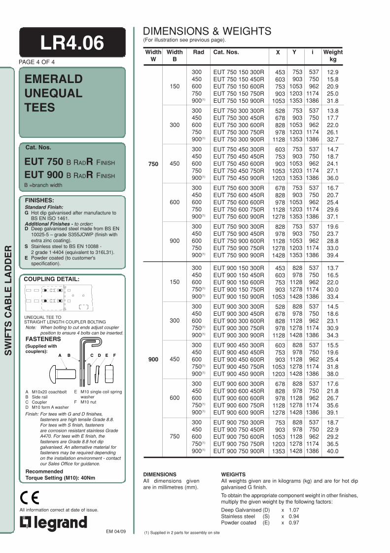
Note: When bolting to cut ends adjust couplerposition to ensure 4 bolts can be inserted.
Cat. Nos.
EMERALD
RecommendedTorque Setting (M10): 40Nm
FINISHES:Standard Finish:G Hot dip galvanised after manufacture to
BS EN ISO 1461.Additional Finishes - to order:D Deep galvanised steel made from BS EN
10025-5 – grade S355JOWP (finish withextra zinc coating).
S Stainless steel to BS EN 10088 -2 grade 1·4404 (equivalent to 316L31).
E Powder coated (to customer'sspecification).
COUPLING DETAIL:
A B C D E F
A M10x20 coachboltB Side railC CouplerD M10 form A washer
E M10 single coil springwasher
F M10 nut
FASTENERS(Supplied withcouplers):
EM 04/09
All information correct at date of issue.
SW
IFT
S C
AB
LE
LA
DD
ER
LR4.06PAGE 4 OF 4
UNEQUALTEES
B =branch width
Weightkg
Y
753903
105312031353
753903
105312031353
753903
105312031353
753903
105312031353
753903
105312031353
828978
112812781428
828978
112812781428
828978
112812781428
828978
112812781428
828978
112812781428
X
453603753903
1053
528678828978
1128
603753903
10531203
678828978
11281278
828978
112812781428
453603753903
1053
528678828978
1128
603753903
10531203
678828978
11281278
753903
105312031353
WidthB
150
300
450
600
900
150
300
450
600
750
Rad
300450600750900(1)
300450600750900(1)
300450600750900(1)
300450600750900(1)
300450600750900(1)
300450600750(1)
900(1)
300450600750(1)
900(1)
300450600750(1)
900(1)
300450600750(1)
900(1)
300450600750(1)
900(1)
i
537750962
11741386
537750962
11741386
537750962
11741386
537750962
11741386
537750962
11741386
537750962
11741386
537750962
11741386
537750962
11741386
537750962
11741386
537750962
11741386
WidthW
750
900
WEIGHTSAll weights given are in kilograms (kg) and are for hot dipgalvanised G finish.
To obtain the appropriate component weight in other finishes,multiply the given weight by the following factors:
Deep Galvanised (D) x 1.07Stainless steel (S) x 0.94Powder coated (E) x 0.97
DIMENSIONSAll dimensions givenare in millimetres (mm).
12.915.820.925.031.8
13.817.722.026.132.7
14.718.724.127.136.0
16.720.725.429.637.1
19.623.728.833.039.4
13.716.522.030.033.4
14.518.623.130.934.3
15.519.625.431.838.0
17.621.826.735.639.1
18.722.929.236.540.0
EUT 750 B RADR FINISH
EUT 900 B RADR FINISH
Cat. Nos.
EUT 750 150 300REUT 750 150 450REUT 750 150 600REUT 750 150 750REUT 750 150 900R
EUT 750 300 300REUT 750 300 450REUT 750 300 600REUT 750 300 750REUT 750 300 900R
EUT 750 450 300REUT 750 450 450REUT 750 450 600REUT 750 450 750REUT 750 450 900R
EUT 750 600 300REUT 750 600 450REUT 750 600 600REUT 750 600 750REUT 750 600 900R
EUT 750 900 300REUT 750 900 450REUT 750 900 600REUT 750 900 750REUT 750 900 900R
EUT 900 150 300REUT 900 150 450REUT 900 150 600REUT 900 150 750REUT 900 150 900R
EUT 900 300 300REUT 900 300 450REUT 900 300 600REUT 900 300 750REUT 900 300 900R
EUT 900 450 300REUT 900 450 450REUT 900 450 600REUT 900 450 750REUT 900 450 900R
EUT 900 600 300REUT 900 600 450REUT 900 600 600REUT 900 600 750REUT 900 600 900R
EUT 900 750 300REUT 900 750 450REUT 900 750 600REUT 900 750 750REUT 900 750 900R
(For illustration see previous page).DIMENSIONS & WEIGHTS
UNEQUAL TEE TOSTRAIGHT LENGTH COUPLER BOLTING
Finish: For tees with G and D finishes,fasteners are high tensile Grade 8.8.For tees with S finish, fastenersare corrosion resistant stainless GradeA470. For tees with E finish, thefasteners are Grade 8.8 hot dipgalvanised. An alternative material forfasteners may be required dependingon the installation environment - contactour Sales Office for guidance.
(1) Supplied in 2 parts for assembly on site
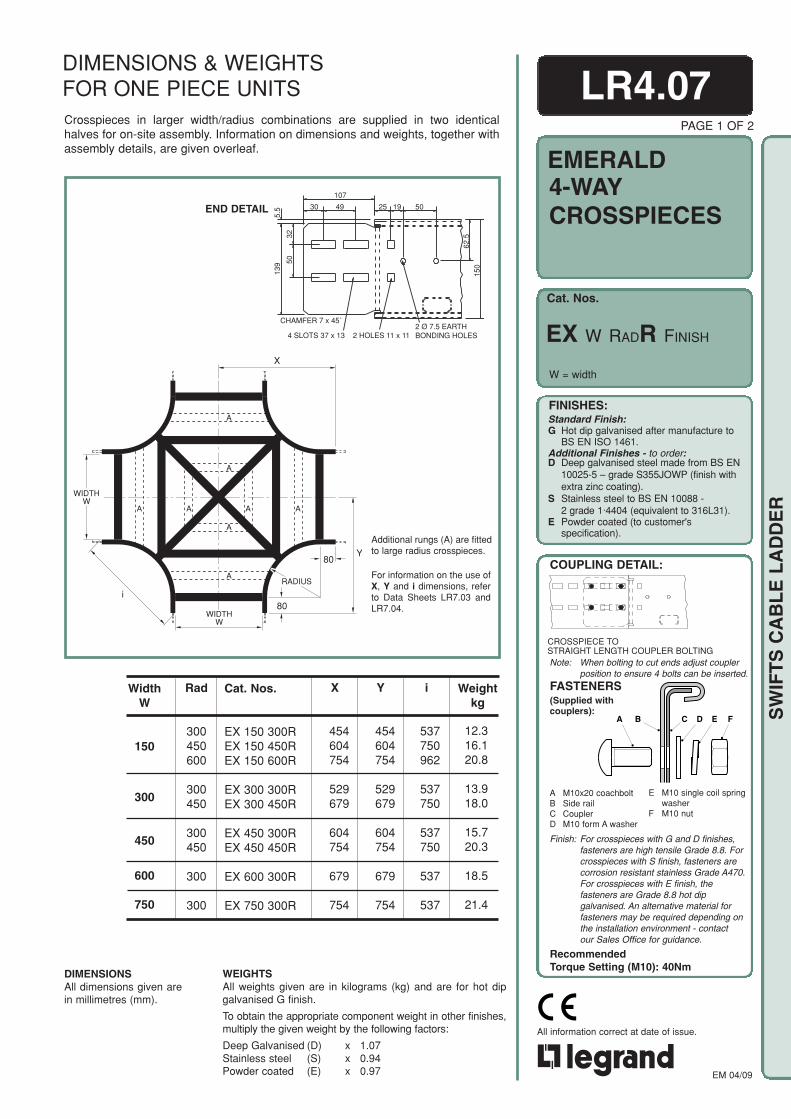
Note: When bolting to cut ends adjust couplerposition to ensure 4 bolts can be inserted.
Cat. Nos.
EMERALD
RecommendedTorque Setting (M10): 40Nm
FINISHES:Standard Finish:G Hot dip galvanised after manufacture to
BS EN ISO 1461.Additional Finishes - to order:D Deep galvanised steel made from BS EN
10025-5 – grade S355JOWP (finish withextra zinc coating).
S Stainless steel to BS EN 10088 -2 grade 1·4404 (equivalent to 316L31).
E Powder coated (to customer'sspecification).
COUPLING DETAIL:
A B C D E F
A M10x20 coachboltB Side railC CouplerD M10 form A washer
E M10 single coil springwasher
F M10 nut
FASTENERS(Supplied withcouplers):
EM 04/09
All information correct at date of issue.
SW
IFT
S C
AB
LE
LA
DD
ER
Crosspieces in larger width/radius combinations are supplied in two identicalhalves for on-site assembly. Information on dimensions and weights, together withassembly details, are given overleaf.
For information on the use ofX, Y and i dimensions, referto Data Sheets LR7.03 andLR7.04.
Additional rungs (A) are fittedto large radius crosspieces.
Weightkg
Rad
300450600
300450
300450
300
300
12.316.120.8
13.918.0
15.720.3
18.5
21.4
WidthW
150
300
450
600
750
Y
454604754
529679
604754
679
754
X
454604754
529679
604754
679
754
i
537750962
537750
537750
537
537
WEIGHTSAll weights given are in kilograms (kg) and are for hot dipgalvanised G finish.
To obtain the appropriate component weight in other finishes,multiply the given weight by the following factors:
Deep Galvanised (D) x 1.07Stainless steel (S) x 0.94Powder coated (E) x 0.97
DIMENSIONSAll dimensions given arein millimetres (mm).
LR4.07PAGE 1 OF 2
4-WAYCROSSPIECES
W = width
Cat. Nos.
EX 150 300REX 150 450REX 150 600R
EX 300 300REX 300 450R
EX 450 300REX 450 450R
EX 600 300R
EX 750 300R
EX W RADR FINISH
DIMENSIONS & WEIGHTSFOR ONE PIECE UNITS
CROSSPIECE TOSTRAIGHT LENGTH COUPLER BOLTING
Finish: For crosspieces with G and D finishes,fasteners are high tensile Grade 8.8. Forcrosspieces with S finish, fasteners arecorrosion resistant stainless Grade A470.For crosspieces with E finish, thefasteners are Grade 8.8 hot dipgalvanised. An alternative material forfasteners may be required depending onthe installation environment - contactour Sales Office for guidance.
Y80
80
RADIUS
i
WIDTHW
WIDTHW
X
A A
A
A
A A
A
A
END DETAIL 30 49
107
25 19 50
62.5
150
139 50
32
5.5
CHAMFER 7 x 45˚
4 SLOTS 37 x 13 2 HOLES 11 x 112 Ø 7.5 EARTHBONDING HOLES

Note: When bolting to cut ends adjust couplerposition to ensure 8 bolts can be
Cat. Nos.
EMERALD
FINISHES:Standard Finish:G Hot dip galvanised after manufacture to
BS EN ISO 1461.Additional Finishes - to order:D Deep galvanised steel made from BS EN
10025-5 – grade S355JOWP (finish withextra zinc coating).
S Stainless steel to BS EN 10088 -2 grade 1·4404 (equivalent to 316L31).
E Powder coated (to customer'sspecification).
COUPLING DETAIL:Also refer toData SheetLR6.01.
A M10x20 coachboltB Side railC CouplerD M10 form A washer
FASTENERS(Supplied with cou-plers):
EM 04/09
All information correct at date of issue.
SW
IFT
S C
AB
LE
LA
DD
ER
LR4.07PAGE 2 OF 2
WEIGHTSAll weights given are in kilograms (kg) and are for hot dipgalvanised G finish.
To obtain the appropriate component weight in otherfinishes, multiply the given weight by the following factors:
Deep Galvanised (D) x 1.07Stainless steel (S) x 0.94Powder coated (E) x 0.97
DIMENSIONSAll dimensions given are inmillimetres (mm).
For information on the use ofX, Y and i dimensions, refer toData Sheets LR7.03 andLR7.04.
DIMENSIONS & WEIGHTSFOR TWO PIECE UNITS
4-WAYCROSSPIECES
EX W RADR FINISH
W = width
ASSEMBLY DETAIL FORTWO PIECE UNITS - detail A(Fasteners included):
A B C DC
A M6 nutB Shakeproof washerC Flat washer
- roofing washers for G and D- form A for S
D M6x16 set screw
Finish: For crosspieces with G and D finishes,fasteners are high tensile Grade 8.8. Forcrosspieces with S finish, fasteners arecorrosion resistant stainless Grade A470.For crosspieces with E finish, thefasteners are Grade 8.8 hot dipgalvanised. An alternative material forfasteners may be required depending onthe installation environment - contactour Sales Office for guidance.
Weightkg
Rad
750900
600750900
600750900
450600750900
450600750900
300450600750900
29.334.4
23.131.837.2
29.534.339.7
22.532.337.843.4
27.836.641.547.5
23.531.639.345.752.4
WidthW
150
300
450
900
600
750
Y
9041054
829979
1129
90410541204
829979
11291279
904105412041354
829979
112912791429
X
9041054
829979
1129
90410541204
829979
11291279
904105412041354
829979
112912791429
i
11741386
96211741386
96211741386
750962
11741386
750962
11741386
537750962
11741386
Cat. Nos.
EX 150 750REX 150 900R
EX 300 600REX 300 750REX 300 900R
EX 450 600REX 450 750REX 450 900R
EX 600 450REX 600 600REX 600 750REX 600 900R
EX 750 450REX 750 600REX 750 750REX 750 900R
EX 900 300REX 900 450REX 900 600REX 900 750REX 900 900R
80
80
RADIUS
i
WIDTHW
X
Y
A
Y
END DETAIL 30 49
107
25 19 50
62.5
150
139 50
32
5.5
CHAMFER 7 x 45˚
4 SLOTS 37 x 13 2 HOLES 11 x 112 Ø 7.5 EARTHBONDING HOLES
Assembly detail for two pieceunits - detail A, see below.
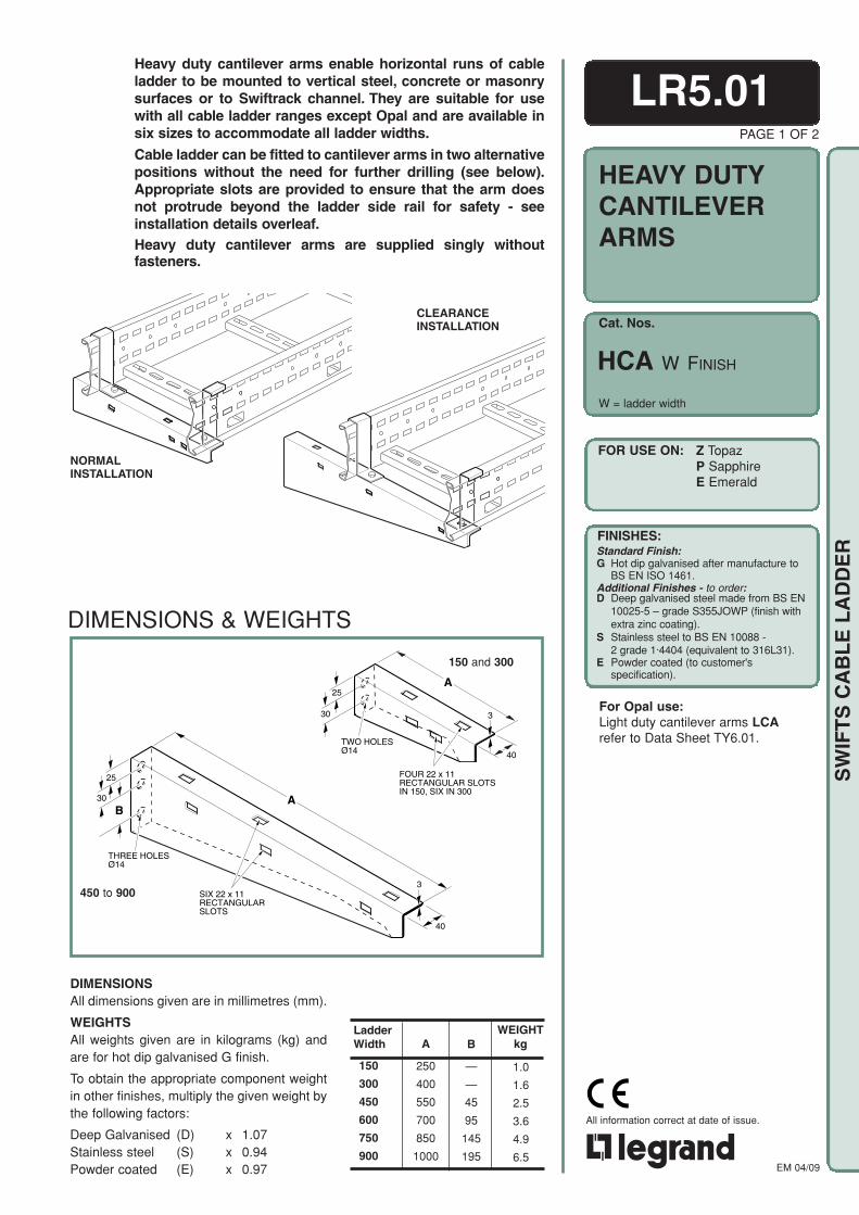
Cat. Nos.
FOR USE ON:
FINISHES:Standard Finish:G Hot dip galvanised after manufacture to
BS EN ISO 1461.Additional Finishes - to order:D Deep galvanised steel made from BS EN
10025-5 – grade S355JOWP (finish withextra zinc coating).
S Stainless steel to BS EN 10088 -2 grade 1·4404 (equivalent to 316L31).
E Powder coated (to customer'sspecification).
EM 04/09
All information correct at date of issue.
SW
IFT
S C
AB
LE
LA
DD
ER
PAGE 1 OF 2
Heavy duty cantilever arms enable horizontal runs of cableladder to be mounted to vertical steel, concrete or masonrysurfaces or to Swiftrack channel. They are suitable for usewith all cable ladder ranges except Opal and are available insix sizes to accommodate all ladder widths.
Cable ladder can be fitted to cantilever arms in two alternativepositions without the need for further drilling (see below).Appropriate slots are provided to ensure that the arm doesnot protrude beyond the ladder side rail for safety - seeinstallation details overleaf.Heavy duty cantilever arms are supplied singly withoutfasteners.
450 to 900
DIMENSIONS & WEIGHTS
150 and 300
CLEARANCEINSTALLATION
NORMALINSTALLATION
B
—
—
45
95
145
195
A
250
400
550
700
850
1000
LadderWidth
1.0
1.6
2.5
3.6
4.9
6.5
WEIGHTkg
150
300
450
600
750
900
LR5.01
HEAVY DUTYCANTILEVERARMS
Z TopazP SapphireE Emerald
HCA W FINISH
W = ladder width
For Opal use:Light duty cantilever arms LCArefer to Data Sheet TY6.01.
DIMENSIONSAll dimensions given are in millimetres (mm).
WEIGHTSAll weights given are in kilograms (kg) andare for hot dip galvanised G finish.
To obtain the appropriate component weightin other finishes, multiply the given weight bythe following factors:
Deep Galvanised (D) x 1.07Stainless steel (S) x 0.94Powder coated (E) x 0.97
A
FOUR 22 x 11RECTANGULAR SLOTSIN 150, SIX IN 300
TWO HOLESØ14
25
30
40
3
SIX 22 x 11RECTANGULARSLOTS
THREE HOLESØ14
B
25
30 A
40
3
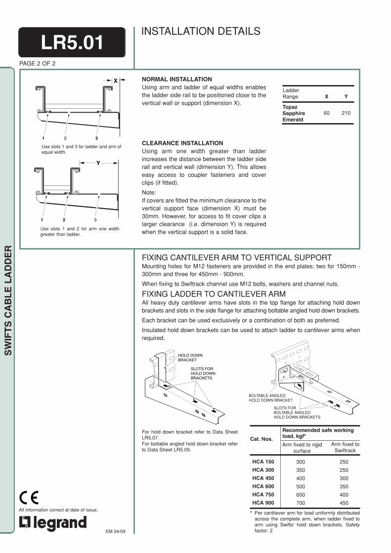
EM 04/09
All information correct at date of issue.
SW
IFT
S C
AB
LE
LA
DD
ER
BOLTABLE ANGLEDHOLD DOWN BRACKET
SLOTS FORBOLTABLE ANGLEDHOLD DOWN BRACKETS
SLOTS FORHOLD DOWNBRACKETS
HOLD DOWNBRACKET
LR5.01PAGE 2 OF 2
FIXING CANTILEVER ARM TO VERTICAL SUPPORTMounting holes for M12 fasteners are provided in the end plates; two for 150mm -300mm and three for 450mm - 900mm.
When fixing to Swiftrack channel use M12 bolts, washers and channel nuts.
FIXING LADDER TO CANTILEVER ARMAll heavy duty cantilever arms have slots in the top flange for attaching hold downbrackets and slots in the side flange for attaching boltable angled hold down brackets.
Each bracket can be used exclusively or a combination of both as preferred.
Insulated hold down brackets can be used to attach ladder to cantilever arms whenrequired.
For hold down bracket refer to Data SheetLR5.07.For boltable angled hold down bracket referto Data Sheet LR5.09.
Recommended safe workingload, kgf*
Arm fixed to rigidsurface
HCA 150
HCA 300
HCA 450
HCA 600
HCA 750
HCA 900
Cat. Nos.Arm fixed to
Swiftrack
300
350
400
500
600
700
250
250
300
350
400
450
* Per cantilever arm for load uniformly distributedacross the complete arm, when ladder fixed toarm using Swifts' hold down brackets. Safetyfactor: 2
INSTALLATION DETAILS
1 2 3
Y
1 2 3
X
X
60
LadderRange
TopazSapphireEmerald
Y
210
Use slots 1 and 2 for arm one widthgreater than ladder.
Use slots 1 and 3 for ladder and arm ofequal width.
NORMAL INSTALLATIONUsing arm and ladder of equal widths enablesthe ladder side rail to be positioned close to thevertical wall or support (dimension X).
CLEARANCE INSTALLATIONUsing arm one width greater than ladderincreases the distance between the ladder siderail and vertical wall (dimension Y). This allowseasy access to coupler fasteners and coverclips (if fitted).
Note:If covers are fitted the minimum clearance to thevertical support face (dimension X) must be30mm. However, for access to fit cover clips alarger clearance (i.e. dimension Y) is requiredwhen the vertical support is a solid face.

Cat. Nos.
FOR USE ON:
FINISHES:Standard Finish:G Hot dip galvanised after manufacture to
BS EN ISO 1461.Additional Finishes - to order:D Deep galvanised steel made from BS EN
10025-5 – grade S355JOWP (finish withextra zinc coating).
S Stainless steel to BS EN 10088 -2 grade 1·4404 (equivalent to 316L31).
E Powder coated (to customer'sspecification).
EM 04/09
All information correct at date of issue.
SW
IFT
S C
AB
LE
LA
DD
ER
LR5.02PAGE 1 OF 2
Wall support brackets are an effective way of fixing anywidth of ladder, running either vertically or horizontally, toa vertical support.
These brackets can be mounted onto Swiftrack channel,structural steelwork or directly to a wall using M10 bolts(not included).
Wall support brackets are available for all ladder rangesand supplied in pairs with bracket to ladder fasteners.
for Cat. Nos. see table
LADDER RANGE
Cat. Nos.
Quantity of Fastenersper Bracket
TOPAZ
ZWSB
4
SAPPHIRE
PWSB
4
EMERALD
EWSB
4
OPAL
OWSB
2
OWSB PWSB(ZWSB and EWSB similar)
INSTALLATIONS
Verticalladder run
Horizontalladder run
WALLSUPPORTBRACKETS
WSB FINISH
O OpalZ TopazP SapphireE Emerald
Note: OWSB not available in D.
Horizontalladder run
Verticalladder run
W W+76
W = ladder width W = ladder width
W W+106

EM 04/09
All information correct at date of issue.
SW
IFT
S C
AB
LE
LA
DD
ER
BA
D
C
3.0
FOUR 37 x 13RECTANGULARSLOTS
THREEØ11HOLES
30
30
30
30 22
DIMENSIONS & WEIGHTS
ZWSB, PWSB,EWSB
OWSB
DIMENSIONSAll dimensions given are in millimetres(mm).
WEIGHTSAll weights given are in kilograms (kg)and are for a pair of brackets in a hot dipgalvanised G finish.
To obtain the appropriate componentweight in other finishes, multiply the givenweight by the following factors:
Deep Galvanised (D) x 1.07Stainless steel (S) x 0.94Powder coated (E) x 0.97
OWSB
ZWSB
PWSB
EWSB
B
38
42
42
42
A
60
75
75
75
DWGHT
kgCat. Nos.
ASSEMBLYHoles are provided for M10 setscrews - length and finish to suit application.
FIXING BRACKETS TO SUPPORTSOnly one fastener is needed to attach each bracket to its support; three attachmentholes are provided to give flexibility when positioning the ladder run.
FIXING BRACKETS TO LADDER - VERTICAL RUNSWhen installing ladder runs vertically, the full quantity of fasteners must be used toattach each bracket to the ladder. (Opal - 2 per bracket, all other ladder ranges - 4 perbracket).
FIXING BRACKETS TO LADDER - HORIZONTAL RUNSWhen installing ladder runs horizontally it is often easiest to mount the lower bracketsto the support, lift the ladder into position then mount the upper brackets. Thisprocedure is especially useful for single person installation.
PAGE 2 OF 2
FASTENERS (included):For quantity required see table on page 1.
OWSB
LOADINGNOTE: The following loading information is applicable to all ladder ranges
except Opal. For loading information and further advice on the Opalrange, contact our Sales Office.
VERTICAL LADDER RUNSFor a vertically mounted ladder installation, the maximum safe working load is300kg per pair of wall support brackets.
HORIZONTAL LADDER RUNSFor a horizontally mounted ladder installation, the wall support brackets should bepitched at 2-3m intervals so that the limiting factor for safe working load is the spanbetween brackets and the ladder width rather than the brackets. For furtherinformation on this type of installation, contact our Sales Office.
ZWSB,PWSB,EWSB
30
30
BA
DC
15
2.0
22
20
20
FIVE 15 x 7OBROUNDSLOTS
THREEØ11HOLES
45.0
86.0
111.0
123.5
C
1.5
9.0
9.0
9.0
0.3
0.8
1.0
1.0
G
C
D
H
J
K
A
B
C
D
B
E
F
LR5.02
A M6x16 setscrewB M6 washerC Side railD BracketE M6 shakeproof washerF M6 nutG M10x20 coachboltH M10 form A washerJ M10 single coil spring washerK M10 nut
Finish: For ladders with G and D finishes,fasteners are high tensile Grade 8.8.For ladders with S finish, fastenersare corrosion resistant stainless GradeA470.
For ladders with E finish, the fastenersare Grade 8.8 hot dip galvanised. Analternative material for fasteners maybe required depending on theinstallation environment - contactour Sales Office for guidance.
RecommendedTorque Setting (M10): 40Nm

Cat. Nos.
FOR USE ON:
FINISHES:Standard Finish:G Hot dip galvanised after manufacture to
BS EN ISO 1461.Additional Finishes - to order:D Deep galvanised steel made from BS EN
10025-5 – grade S355JOWP (finish withextra zinc coating).
S Stainless steel to BS EN 10088 -2 grade 1·4404 (equivalent to 316L31).
E Powder coated (to customer'sspecification).
EM 04/09
All information correct at date of issue.
SW
IFT
S C
AB
LE
LA
DD
ER
PAGE 1 OF 2
LR5.03
for Cat. Nos. see table
90° end connectors are used to fix the end of a cable ladderrun to a vertical surface (steel, concrete or masonry). Theyare supplied in pairs with bracket to ladder fasteners.
90°ENDCONNECTORS
B FINISH
Z TopazP SapphireE Emerald
Cat. Nos.
ZB
PB
EB
A
127
127
127
B
47
47
47
C
1.5
2.0
2.0
D
84
115
140
E
50
75
75
C
A
D
B
E
TWOØ11HOLES
FOUR 37 x 13RECTANGULARSLOTS
A
D
B
E
C
EIGHT 37 x 13RECTANGULARSLOTS
TWOØ11HOLES
DIMENSIONS & WEIGHTS
WEIGHTkg
0.3
0.5
0.7
LADDER RANGE
Cat. Nos.
TOPAZ
ZB
SAPPHIRE
PB
EMERALD
EB
INSTALLATION
PB and EB
ZB
CONNECTOR TO LADDERFASTENERS (included):Four fasteners per bracket.ZB, PB, EB
M10x20 coachboltM10 form A washerM10 single coil spring washerM10 nut
Finish: For ladders with G and D finishes,fasteners are high tensile Grade 8.8.For ladders with S finish, fastenersare corrosion resistant stainless GradeA470.
For ladders with E finish, the fastenersare Grade 8.8 hot dip galvanised. Analternative material for fasteners may berequired depending on the installationenvironment - contact our Sales Officefor guidance.
RecommendedTorque Setting (M10): 40NmCONNECTOR TO SUPPORTFASTENERS:
Slots are provided for M10setscrews- length and finish to suit application.
DIMENSIONSAll dimensions given are in millimetres (mm).
WEIGHTSAll weights given are in kilograms (kg) andare for two items (one 90° connector set) ina hot dip galvanised G finish.
To obtain the appropriate component weightin other finishes, multiply the given weight bythe following factors:
Deep Galvanised (D) x 1.07Stainless steel (S) x 0.94Powder coated (E) x 0.97

EM 04/09
All information correct at date of issue.
SW
IFT
S C
AB
LE
LA
DD
ER
90° end connectors are used to fix the end of a cable ladder run to avertical surface (steel, concrete or masonry).They can also be used asa tee bracket for joining Opal to Opal ladder, refer to Data SheetLR6.06.
90° end connectors are supplied in pairs with bracket to ladderfasteners.
LR5.03PAGE 2 OF 2
90°ENDCONNECTORS
Cat. Nos.
OB FINISH
FOR USE ON: O Opal
INSTALLATION
DIMENSIONSAll dimensions given are in millimetres (mm).
WEIGHTSThe weight given is in kilograms (kg) and isfor two items (one 90° connector set) in ahot dip galvanised G finish.
To obtain the appropriate componentweight in other finishes, multiply the givenweight by the following factors:
Stainless steel (S) x 0.94Powder coated (E) x 0.97
C
2.0
WEIGHTkg
0.3
B
100
D
45
C
A
D
B
SIXTEEN 12 x 7OBROUND SLOTS
A
100
DIMENSIONS & WEIGHTS
CONNECTOR TO LADDERFASTENERS (included):Two fasteners per bracket
M6x16 setscrewM6 washerM6 shakeproof washerM6 nut
Finish: For ladders with G finish, fastenersare high tensile Grade 8.8.For ladders with S finish, fastenersare corrosion resistant stainless GradeA470.
For ladders with E finish, thefasteners are Grade 8.8 hot dipgalvanised. An alternative material forfasteners may be required dependingon the installation environment -contact our Sales Office for guidance.
CONNECTOR TO SUPPORTFASTENERS:
Holes are provided for M6 setscrews- length and finish to suit application.
FINISHES:Standard Finish:G Hot dip galvanised after manufacture to
BS EN ISO 1461.Additional Finishes - to order:S Stainless steel to BS EN 10088 -
2 grade 1·4404 (equivalent to 316L31).E Powder coated (to customer's
specification).
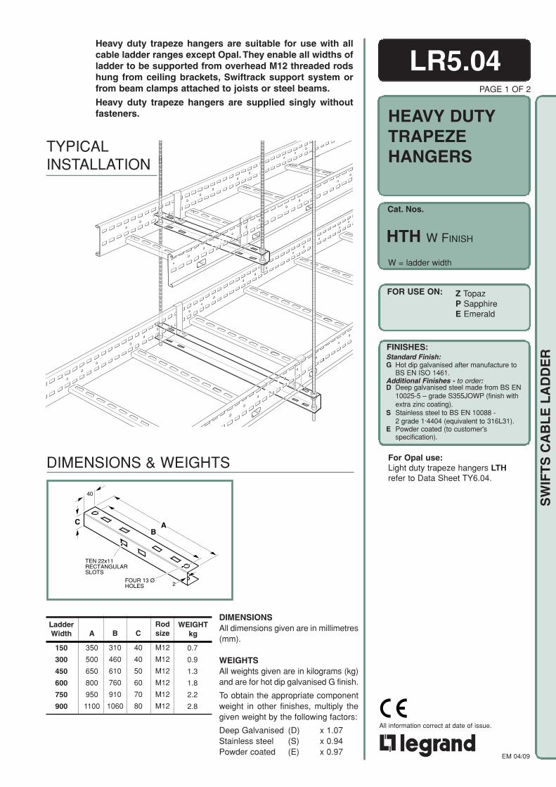
Cat. Nos.
FOR USE ON:
FINISHES:Standard Finish:G Hot dip galvanised after manufacture to
BS EN ISO 1461.Additional Finishes - to order:D Deep galvanised steel made from BS EN
10025-5 – grade S355JOWP (finish withextra zinc coating).
S Stainless steel to BS EN 10088 -2 grade 1·4404 (equivalent to 316L31).
E Powder coated (to customer'sspecification).
EM 04/09
All information correct at date of issue.
SW
IFT
S C
AB
LE
LA
DD
ER
LR5.04PAGE 1 OF 2
HEAVY DUTYTRAPEZEHANGERS
HTH W FINISH
W = ladder width
Z TopazP SapphireE Emerald
Heavy duty trapeze hangers are suitable for use with allcable ladder ranges except Opal. They enable all widths ofladder to be supported from overhead M12 threaded rodshung from ceiling brackets, Swiftrack support system orfrom beam clamps attached to joists or steel beams.
Heavy duty trapeze hangers are supplied singly withoutfasteners.
TYPICALINSTALLATION
DIMENSIONS & WEIGHTS For Opal use:Light duty trapeze hangers LTHrefer to Data Sheet TY6.04.
DIMENSIONSAll dimensions given are in millimetres(mm).
WEIGHTSAll weights given are in kilograms (kg)and are for hot dip galvanised G finish.
To obtain the appropriate componentweight in other finishes, multiply thegiven weight by the following factors:
Deep Galvanised (D) x 1.07Stainless steel (S) x 0.94Powder coated (E) x 0.97
FOUR 13 ØHOLES 2
TEN 22x11RECTANGULARSLOTS
40
C AB
B
310
460
610
760
910
1060
C
40
40
50
60
70
80
Rodsize
M12
M12
M12
M12
M12
M12
0.7
0.9
1.3
1.8
2.2
2.8
A
350
500
650
800
950
1100
LadderWidth
150
300
450
600
750
900
WEIGHTkg

EM 04/09
All information correct at date of issue.
SW
IFT
S C
AB
LE
LA
DD
ER
LR5.04INSTALLATION DETAILS
Insulated versions of hold down clips (*F IN) and hold down brackets (*J IN) areavailable if required.
For further details of hold down clips and hold down brackets refer to Data SheetsLR5.06 and LR5.07.
Boltable angled hold down bracket(*P)
Hold down bracket (*J)Hold down clip (*F)
LADDER TO TRAPEZE HANGERAll trapeze hangers are provided with fixing slots correctly positioned to accept anyof Swifts' hold down brackets or clips without the need for further drilling. The slotswill accept all cable ladder ranges except Opal which should be installed using lightduty trapeze hangers (LTH). Refer to Data Sheet TY6.04.
A M12 threaded rodB M12 nutC WasherD Upper flangeE Lower flange
ABCD
E
TYPE C
ABCD
TYPE B
ABCD
BC
E
TYPE A
TYPE A
400
400
400
500
500
500
TYPE B
240
240
240
300
300
300
TYPE C
120
120
120
150
150
150
HTH 150
HTH 300
HTH 450
HTH 600
HTH 750
HTH 900
Cat. Nos.
* Per trapeze hanger for load uniformlydistributed across the complete hanger.Safety factor: 2
TRAPEZE HANGER TO THREADED RODThere are three alternative methods of fixing trapeze hangers to threaded rodsas shown below. The recommended safe working load for each width andmethod of fixing is given in the table.
Recommended safe workingload, kgf*
PAGE 2 OF 2

Cat. Nos.
FOR USE ON:
FINISHES:Standard Finish:G Hot dip galvanised after manufacture to
BS EN ISO 1461.Additional Finishes - to order:D Deep galvanised steel made from BS EN
10025-5 – grade S355JOWP (finish withextra zinc coating).
S Stainless steel to BS EN 10088 -2 grade 1·4404 (equivalent to 316L31).
E Powder coated (to customer'sspecification).
EM 04/09
All information correct at date of issue.
SW
IFT
S C
AB
LE
LA
DD
ER
PAGE 1 OF 2
Hanger rod brackets are an effective way of supportingany width of cable ladder off studding without the need forspecial trapeze hangers or cut lengths of channel.
They are particularly useful when space to the sides of aladder run is restricted or where maximum headroom isrequired below a ladder run.
Hanger rod brackets are available for all ladder ranges andsupplied in pairs with bracket to ladder fasteners.
for Cat. Nos. see table
LADDER RANGE
Cat. Nos.
Quantity of Fastenersper Bracket
TOPAZ
ZRB
4
SAPPHIRE
PRB
4
EMERALD
ERB
4
OPAL
ORB
2
Multiple levelinstallation
ORB
PRB(ZRB and ERB similar)
INSTALLATIONS
LR5.05
HANGERRODBRACKETS
RB FINISH
O OpalZ TopazP SapphireE Emerald
Note: ORB not available in D.
When hanger rod brackets are fitted toladder, covers can not be used.

EM 04/09
All information correct at date of issue.
SW
IFT
S C
AB
LE
LA
DD
ER
ORB ZRB, PRB,ERB
ORB
ZRB
PRB
ERB
Cat. Nos.
120
A
15
B
3.0
FOUR 37 x 13RECTANGULARSLOTS
TWOØ13HOLES
15
FIVE 15 x 7OBROUNDSLOTS
100
A
B
TWOØ13HOLES
3.0
LR5.05PAGE 2 OF 2
G C D H J K
BRACKET TO LADDERFASTENERS (included):For quantity required see table on page 1.
ORB
ZRB,PRB,ERB
DIMENSIONS & WEIGHTS
0.6
0.9
1.0
1.1
A
46
80
104
127
WEIGHTkgB
41
48
48
48
DIMENSIONSAll dimensions given are in millimetres (mm).
WEIGHTSAll weights given are in kilograms (kg)and are for a pair of brackets in a hot dipgalvanised G finish.
To obtain the appropriate componentweight in other finishes, multiply the givenweight by the following factors:
Deep Galvanised (D) x 1.07Stainless steel (S) x 0.94Powder coated (E) x 0.97
ASSEMBLYHanger rod brackets for Opal ladders are designed for use with M10 threaded rod.Brackets for use with all other ladder ranges can be used with either M10 or M12threaded rod.
BRACKET TO LADDERBrackets are fixed directly to the outside of the ladder siderail as shown. The slotsin the side rail and the bracket provide sufficient movement to align the bracketwith the threaded rod.
BRACKET TO THREADED RODFour nuts and washers are used to fix each bracket to the threaded rod. Thisensures the stability of the support and also optimises the safe working load.
LOADINGThe safe working load of all brackets, apart from those used on Opal, is 400kg perpair of brackets. For information on the safe working load of Opal brackets,contact our Sales Office.
When several levels of ladder are mounted on the same threaded rods, it isimportant to ensure that the total load on any pair of rods does not exceed the safeworking load of the rods or their attachment points.
A C D B E FB
A M6x16 setscrewB M6 washerC Side railD BracketE M6 shakeproof
washerF M6 nut
G M10x20 coachboltH M10 form A washerJ M10 single coil
spring washerK M10 nut
Finish: For ladders with G and D finishes,fasteners are high tensile Grade 8.8.For ladders with S finish, fastenersare corrosion resistant stainless GradeA470.
For ladders with E finish, the fastenersare Grade 8.8 hot dip galvanised. Analternative material for fasteners maybe required depending on theinstallation environment - contactour Sales Office for guidance.
RecommendedTorque Setting (M10): 40Nm
A
B
C
D
A M10 or M12 threaded rodB Hanger rod bracketC M10 or M12 form A washerD M10 or M12 nut
BRACKET TO THREADED RODFASTENERS (not included):

Cat. Nos.
FOR USE ON:
FINISHES:Standard Finish:G Hot dip galvanised after manufacture to
BS EN ISO 1461.Additional Finishes - to order:D Deep galvanised steel made from BS EN
10025-5 – grade S355JOWP (finish withextra zinc coating).
S Stainless steel to BS EN 10088 -2 grade 1·4404 (equivalent to 316L31).
E Powder coated (to customer'sspecification).
EM 04/09
All information correct at date of issue.
SW
IFT
S C
AB
LE
LA
DD
ER
018A-INS HOLD DOWN CLIPP.3017A-HOLD DOWN CLIP
PAGE 1 OF 2
HOLD DOWNCLIPS & INSULATED HOLDDOWN CLIPS
Hold down clips are used for fixing cable ladder to trapezehangers, Swiftrack channel or other flat support surfaces.They are fitted on the outside of the ladder side rail.
Insulated versions for stainless steel ladder are available.
Hold down clips are supplied singly without fasteners.Insulated hold down clips are supplied with the requirednylon insulating pad, bush and washers.
for Cat. Nos. see table
ZF, PF, EF Cat. Nos.
OF
ZF
PF
EF
WEIGHTkg
2.2
6.9
6.9
6.9
INSULATED HOLD DOWN CLIPF
STANDARD HOLD DOWN CLIPF IN
INSTALLATIONS
TOPAZ
ZF
ZF IN
OPAL
OF
OF IN
SAPPHIRE
PF
PF IN
EMERALD
EF
EF IN
LADDER RANGE
Cat. Nos.
Cat. Nos.
DIMENSIONS & WEIGHTS
Hold down clips shown are suitable for Topaz, Sapphire and Emeraldladders (with return flange). Clips used for Opal ladder have a lesspronounced single bend.
STANDARD HOLD DOWN CLIP
INSULATED HOLD DOWN CLIP
LR5.06
F FINISH
F IN FINISH
O Opal Z Topaz P Sapphire E Emerald
OF
DIMENSIONSAll dimensions given are in millimetres (mm).
WEIGHTSAll weights given are in kilograms(kg) and are for 100 clips in a hotdip galvanised G finish.
To obtain the appropriate component weight in other finishes, multiply the given weightby the following factors:
Deep Galvanised (D) x 1.07Stainless steel (S) x 0.94Powder coated (E) x 0.97
Note: OF and OF IN not available in D.
ONE HOLE Ø11
3
4065
15
P.3019A-Z,P,E-CLIP ISO
ONE HOLE Ø7.5
40
24
33
O.3012A-OF DIMS
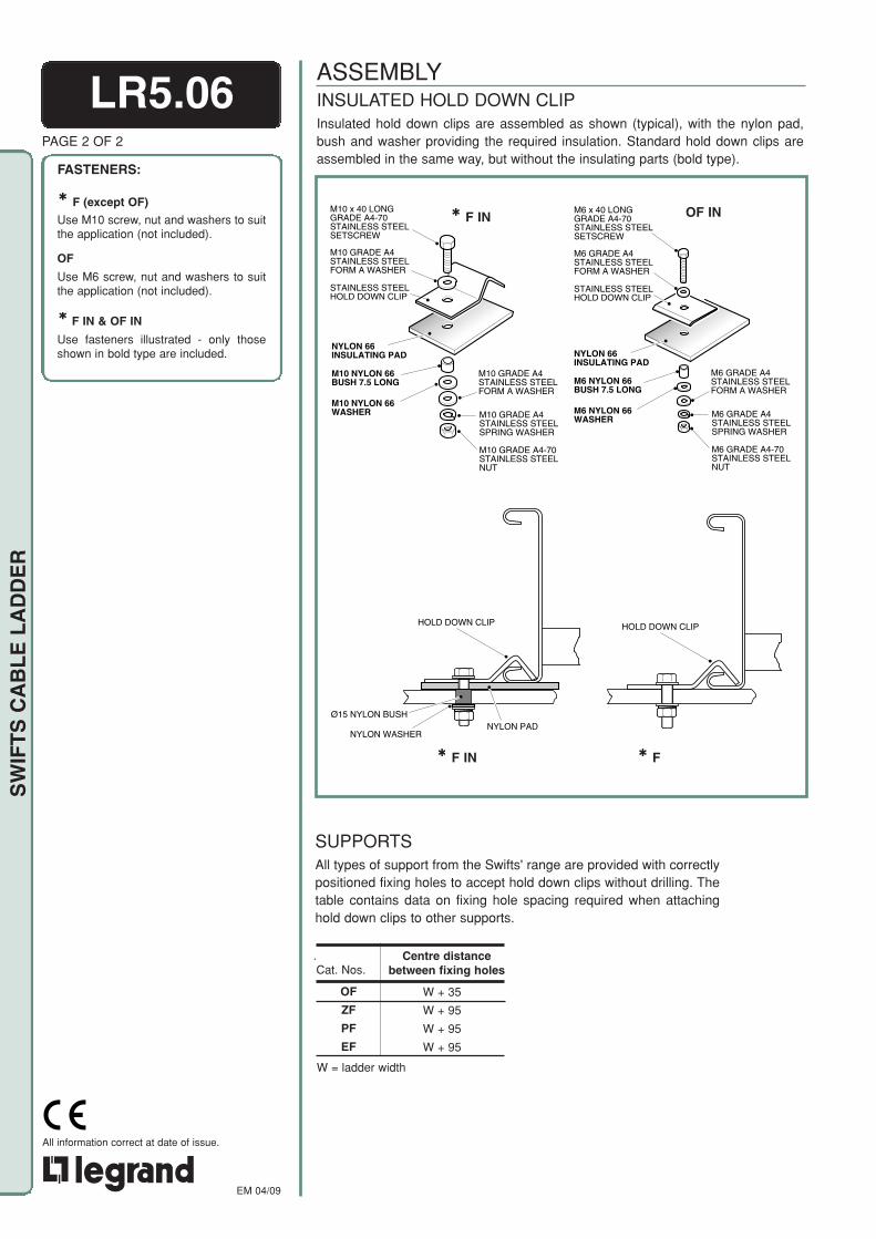
EM 04/09
All information correct at date of issue.CELOGO-001 black
SW
IFT
S C
AB
LE
LA
DD
ER
NYLON PADØ15 NYLON BUSH
NYLON WASHER
HOLD DOWN CLIP HOLD DOWN CLIP
P.3021A-Z,P,E CLIP FIX
INSULATED HOLD DOWN CLIPInsulated hold down clips are assembled as shown (typical), with the nylon pad,bush and washer providing the required insulation. Standard hold down clips areassembled in the same way, but without the insulating parts (bold type).
ASSEMBLYLR5.06
PAGE 2 OF 2
FASTENERS:
F (except OF)
Use M10 screw, nut and washers to suitthe application (not included).
OF
Use M6 screw, nut and washers to suitthe application (not included).
F IN & OF IN
Use fasteners illustrated - only thoseshown in bold type are included.
F IN F
SUPPORTSAll types of support from the Swifts' range are provided with correctlypositioned fixing holes to accept hold down clips without drilling. Thetable contains data on fixing hole spacing required when attachinghold down clips to other supports.
Centre distance between fixing holes
.Cat. Nos.
OF
ZF
PF
EF
W + 35
W + 95
W + 95
W + 95
F IN OF INM10 x 40 LONG GRADE A4-70 STAINLESS STEEL SETSCREW
M10 GRADE A4 STAINLESS STEEL FORM A WASHER
NYLON 66 INSULATING PAD
M10 NYLON 66 BUSH 7.5 LONG
M10 NYLON 66 WASHER
STAINLESS STEEL HOLD DOWN CLIP
M10 GRADE A4-70 STAINLESS STEEL NUT
M10 GRADE A4 STAINLESS STEEL SPRING WASHER
M10 GRADE A4 STAINLESS STEEL FORM A WASHER
M6 x 40 LONG GRADE A4-70 STAINLESS STEEL SETSCREW
M6 GRADE A4 STAINLESS STEEL FORM A WASHER
NYLON 66 INSULATING PAD
M6 NYLON 66 BUSH 7.5 LONG
M6 NYLON 66 WASHER
M6 GRADE A4-70 STAINLESS STEEL NUT
M6 GRADE A4 STAINLESS STEEL SPRING WASHER
M6 GRADE A4 STAINLESS STEEL FORM A WASHER
STAINLESS STEEL HOLD DOWN CLIP
W = ladder width

Cat. Nos.
FOR USE ON:
FINISHES:Standard Finish:G Hot dip galvanised after manufacture to
BS EN ISO 1461.Additional Finishes - to order:D Deep galvanised steel made from BS EN
10025-5 – grade S355JOWP (finish withextra zinc coating).
S Stainless steel to BS EN 10088 - 2 grade 1·4404 (equivalent to 316L31).
E Powder coated (to customer's specification).
EM 04/09
All information correct at date of issue.CELOGO-001 black
SW
IFT
S C
AB
LE
LA
DD
ER
P.3023A-INS HOLD DOWN BRKTP.3022B-HOLD DOWN BRKT
J ININSULATED HOLD DOWN BRACKET
Hold down brackets are used for fixing cable ladder tocantilever arms, trapeze hangers, Swiftrack channel orother flat support surfaces.
They can be fitted on the inside or outside of the ladderside rail, but when used with other items from the Swifts'range refer to the relevant data sheet for specific orienta-tion details.
Insulated versions for stainless steel ladder are available.
Hold down brackets are supplied singly without fasteners.Insulated hold down brackets are supplied with therequired nylon insulating pad, bush and washers.
INSTALLATIONS
STANDARD HOLD DOWN BRACKETJ
TOPAZ
ZJ
ZJ IN
OPAL
OJ
OJ IN
SAPPHIRE
PJ
PJ IN
EMERALD
EJ
EJ IN
LADDER RANGE
Cat. Nos.
Cat. Nos.
STANDARD HOLD DOWN BRACKET
INSULATED HOLD DOWN BRACKET
Cat.Nos.
OJ
ZJ
PJ
EJ
B
23
31
31
31
WEIGHTkg
11.0
17.0
19.0
21.0
DIMENSIONS & WEIGHTS
ZJ, PJ,EJ
OJ
LR5.07PAGE 1 OF 2
HOLD DOWNBRACKETS &INSULATED HOLDDOWN BRACKETS
J FINISH
J IN FINISH
for Cat. Nos. see table
O Opal Z Topaz P Sapphire E Emerald
A
50
103
128
153
DIMENSIONSAll dimensions given are in millimetres (mm).
WEIGHTSAll weights given are in kilograms(kg) and are for 100 brackets in ahot dip galvanised G finish.
To obtain the appropriate component weight in other finishes, multiply the given weightby the following factors:
Deep Galvanised (D) x 1.07
Stainless steel (S) x 0.94Powder coated (E) x 0.97
Note: OJ and OJ IN not available in D.
1040
33
2
ONE 14 x 7 SLOT
A
B
O.3017-OJ DIMS
40B
A3
ONE HOLE Ø11
39
18
P.3024A-Z,P,E HD BKT ISO

EM 04/09
All information correct at date of issue.CELOGO-001 black
SW
IFT
S C
AB
LE
LA
DD
ER
HOLD DOWN BRACKETHOLD DOWN BRACKET
NYLON PADØ15 NYLON BUSH
NYLON WASHER
P.3026A-Z,P,E HD BKT FIX
Cat. Nos.
OJ
ZJ
PJ
EJ
W - 38
W - 44
W - 44
W - 44
W + 62
W + 80
W + 80
W + 80
Centre distance between fixing holesInside ladder Outside ladder
OJ IN
M10 x 40 LONG GRADE A4-70 STAINLESS STEEL SETSCREW
M10 GRADE A4 STAINLESS STEEL FORM A WASHER
NYLON 66 INSULATING PAD
M10 NYLON 66 BUSH 7.5 LONG
M10 NYLON 66 WASHER
M10 GRADE A4-70 STAINLESS STEEL NUT
M10 GRADE A4 STAINLESS STEEL SPRING WASHER
M10 GRADE A4 STAINLESS STEEL FORM A WASHER
STAINLESS STEEL HOLD DOWN BRACKET
J IN J
LR5.07PAGE 2 OF 2
FASTENERS:
J (except OJ)
Use M10 screw, nut and washers to suitthe application (not included).
OJ
Use M6 screw, nut and washers to suitthe application (not included).
J IN & OJ IN
Use fasteners illustrated - only those inbold type are included.
ASSEMBLYINSULATED HOLD DOWN BRACKETInsulated hold down brackets are assembled as shown (typical), with the nylon pad,bush and washer providing the required insulation. Standard hold down bracketsare assembled in the same way, but without the insulating parts (bold type).
SUPPORTSAll types of support from the Swifts' range are provided with correctlypositioned fixing holes to accept hold down brackets without drilling.The table contains data on fixing hole spacing required when attachinghold down brackets to other supports.
W = ladder width
M6 x 40 LONG GRADE A4-70 STAINLESS STEEL SETSCREW
M6 GRADE A4 STAINLESS STEEL FORM A WASHER
NYLON 66 INSULATING PAD
M6 NYLON 66 BUSH 7.5 LONG
M6 NYLON 66 WASHER
M6 GRADE A4-70 STAINLESS STEEL NUT
M6 GRADE A4 STAINLESS STEEL SPRING WASHER
M6 GRADE A4 STAINLESS STEEL FORM A WASHER
STAINLESS STEEL HOLD DOWN BRACKET
O.3018-OJ IN EXP

Cat. Nos.
FOR USE ON:
FINISHES:Standard Finish:G Hot dip galvanised after manufacture to
BS EN ISO 1461.Additional Finishes - to order:D Deep galvanised steel made from BS EN
10025-5 – grade S355JOWP (finish withextra zinc coating).
S Stainless steel to BS EN 10088 - 2 grade 1·4404 (equivalent to 316L31).
E Powder coated (to customer's specification).
EM 04/09
All information correct at date of issue.CELOGO-001 black
SW
IFT
S C
AB
LE
LA
DD
ER
P.3029A-N/SWIFTRACK 1
P.3030A-N/SWIFTRACK 2
PAGE 1 OF 1
Boltable hold down brackets enable all ranges of cableladder except Opal to be secured to either Swiftrack orfabricated structural steel supports. Brackets can be fittedwherever supports are available along the length of theladder and fit to the inside of the ladder side rails thusminimising the total width required.
Boltable hold down brackets are supplied singly withbracket to ladder fasteners.
for Cat. Nos. see table
INSTALLATIONS
SUPPORT UNDER RUNGSUPPORT BETWEEN RUNGS
TOPAZ
ZN
SAPPHIRE
PN
EMERALD
EN
LADDER RANGE
Cat. Nos.
DIMENSIONS & WEIGHTS
18
3
FOUR 37x13RECTANGULARSLOTS
55
55
180
45
A
60
When attaching boltable hold down brackets to fabricated structuralsteel supports, the spacing between fixing holes should be W-64mm,where W is the ladder width.
DIMENSIONSAll dimensions given are in millimetres (mm).
WEIGHTSAll weights given are in kilograms (kg) andare for a single bracket in a hot dip gal-vanised G finish.
To obtain the appropriate component weightin other finishes, multiply the given weight bythe following factors:
Deep Galvanised (D) x 1.07Stainless steel (S) x 0.94Powder coated (E) x 0.97
LR5.08
BOLTABLEHOLD DOWNBRACKETS
N FINISH
Z Topaz P Sapphire E Emerald
A
43.0
68.5
80.5
Cat. Nos.
ZN
PN
EN
WEIGHTkg
0.2
0.3
0.3
For fixing cable ladder to Swifts' cantilever arms or trapeze hangersuse boltable angled hold down bracket P; refer to Data SheetLR5.09.
BRACKET TO LADDER FASTENERS (included):One fastener per bracket.
ZN, PN, EN:M10 x 20 coachboltM10 form A washerM10 single coil spring washerM10 nut
Finish: For ladders with G and D finishes, Fasteners are high tensile Grade 8.8. For ladders with S finish, fasteners are corrosion resistant stainless Grade A470.
For ladders with E finish, the fasteners are Grade 8.8 hot dip galvanised. An alternative material for fasteners may be required depending on the installation environment - contactour Sales Office for guidance.
BRACKET TO SUPPORT FASTENERS (not included):Slots are provided for M10 setscrews - length to suit application.
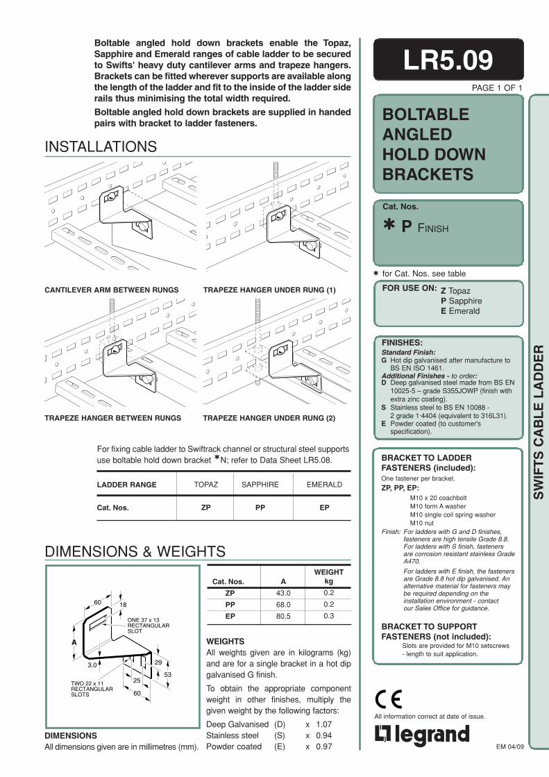
Cat. Nos.
FOR USE ON:
FINISHES:Standard Finish:G Hot dip galvanised after manufacture to
BS EN ISO 1461.Additional Finishes - to order:D Deep galvanised steel made from BS EN
10025-5 – grade S355JOWP (finish withextra zinc coating).
S Stainless steel to BS EN 10088 - 2 grade 1·4404 (equivalent to 316L31).
E Powder coated (to customer's specification).
EM 04/09
All information correct at date of issue.CELOGO-001 black
SW
IFT
S C
AB
LE
LA
DD
ER
P.3036A-P/OVER HTH
P.3034A-P/TRAPEZE
P.3035A-P/LTH
P.3033A-P/CANT ARM
TRAPEZE HANGER UNDER RUNG (1)
TRAPEZE HANGER UNDER RUNG (2)
PAGE 1 OF 1
LR5.09
BOLTABLEANGLEDHOLD DOWNBRACKETS
P FINISH
for Cat. Nos. see table
Boltable angled hold down brackets enable the Topaz,Sapphire and Emerald ranges of cable ladder to be securedto Swifts' heavy duty cantilever arms and trapeze hangers.Brackets can be fitted wherever supports are available alongthe length of the ladder and fit to the inside of the ladder siderails thus minimising the total width required.
Boltable angled hold down brackets are supplied in handedpairs with bracket to ladder fasteners.
INSTALLATIONS
CANTILEVER ARM BETWEEN RUNGS
TRAPEZE HANGER BETWEEN RUNGS
For fixing cable ladder to Swiftrack channel or structural steel supportsuse boltable hold down bracket N; refer to Data Sheet LR5.08.
LADDER RANGE
Cat. Nos.
SAPPHIRE
PP
TOPAZ
ZP
EMERALD
EP
DIMENSIONSAll dimensions given are in millimetres (mm).
WEIGHTkg
0.2
0.2
0.3
A
43.0
68.0
80.5
DIMENSIONS & WEIGHTS
TWO 22 x 11 RECTANGULAR SLOTS
29
5325
60
A
60 18
3.0
ONE 37 x 13 RECTANGULAR SLOT
Cat. Nos.
ZP
PP
EP
BRACKET TO LADDER FASTENERS (included):One fastener per bracket.
ZP, PP, EP:M10 x 20 coachboltM10 form A washerM10 single coil spring washerM10 nut
Finish: For ladders with G and D finishes, fasteners are high tensile Grade 8.8. For ladders with S finish, fasteners are corrosion resistant stainless Grade A470.
For ladders with E finish, the fasteners are Grade 8.8 hot dip galvanised. An alternative material for fasteners may be required depending on the installation environment - contact our Sales Office for guidance.
BRACKET TO SUPPORT FASTENERS (not included):
Slots are provided for M10 setscrews - length to suit application.
WEIGHTSAll weights given are in kilograms (kg)and are for a single bracket in a hot dipgalvanised G finish.
To obtain the appropriate componentweight in other finishes, multiply thegiven weight by the following factors:
Deep Galvanised (D) x 1.07Stainless steel (S) x 0.94Powder coated (E) x 0.97
Z Topaz P Sapphire E Emerald

Cat. Nos.
FOR USE ON:
FINISHES:
EM 04/09
All information correct at date of issue.CELOGO-001 black
SW
IFT
S C
AB
LE
LA
DD
ER
P.3052A-PAMB VERTICAL/BOX
P.3053A-PAMB HORIZONTAL/BOXP.3051A-ANCIL. MOUNTING BKT
PAGE 1 OF 2
Ancillary mounting brackets are designed to enable ancillaryequipment to be mounted to horizontal or vertical cable lad-der runs. They can be used singly to support small items, orany number can be used for larger or heavier items.
Ancillary mounting brackets are supplied singly with bracketto ladder fasteners.
LR5.10
AMB W FINISH
W = ladder width
INSTALLATIONS
DIMENSIONS & WEIGHTS
Ladder Width (W)
150
300
450
600
750
900
t
1.5
1.5
1.5
1.5
2.0
2.0
0.6
0.7
0.8
1.0
1.4
1.6
WEIGHTkg
ANCILLARYMOUNTINGBRACKETS
O/- OpalFOR USE ON:
BRACKET TO LADDER FASTENERS (included):
M10x20 coachboltM10 form A washerM10 single coil spring washerM10 nut
Finish: For ladders with G and D finishes, fasteners are high tensile Grade 8.8. For ladders with S finish, fasteners are corrosion resistant stainless GradeA470.
For ladders with E finish, the fasteners are Grade 8.8 hot dip galvanised. An alternative material for fasteners may be required depending on the installation environment - contact our Sales Office for guidance.
RecommendedTorque Setting (M10): 40Nm
BRACKET TO ANCILLARY FASTENERS (not included):Slots are provided for attaching ancillary items.
Four fasteners per bracket
FINISHES:Standard Finish:G Hot dip galvanised after manufacture to
BS EN ISO 1461.Additional Finishes - to order:D Deep galvanised steel made from BS EN
10025-5 – grade S355JOWP (finish withextra zinc coating).
S Stainless steel to BS EN 10088 - 2 grade 1·4404 (equivalent to 316L31).
E Powder coated (to customer's specification).
DIMENSIONSAll dimensions given are in millimetres(mm).
WEIGHTSAll weights given are in kilograms (kg) andare for a single item in a hot dip galvanisedG finish.
To obtain the appropriate component weightin other finishes, multiply the given weightby the following factors:
Deep Galvanised (D) x 1.07Stainless steel (S) x 0.94 Powder coated (E) x 0.97
3
t
60
FOUR 37 x 13 RECTANGULAR SLOTS
140
Z Topaz P Sapphire E Emerald
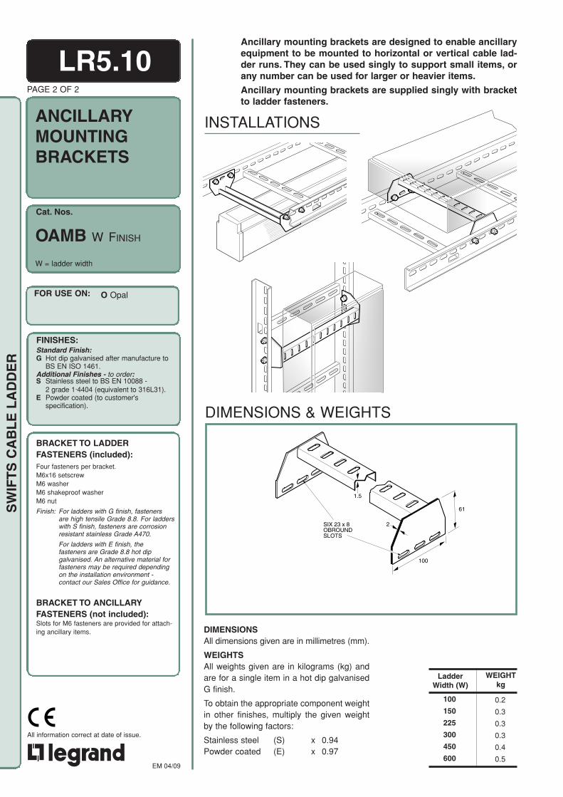
Cat. Nos.
EM 04/09
All information correct at date of issue.CELOGO-001 black
SW
IFT
S C
AB
LE
LA
DD
ER
DIMENSIONS & WEIGHTS
LR5.10
OAMB W FINISH
W = ladder width
WEIGHTkg
0.2
0.3
0.3
0.3
0.4
0.5
100
150
225
300
450
600
Ladder Width (W)
ANCILLARYMOUNTINGBRACKETS
O.3034A-OAMB VERT/BOX
Ancillary mounting brackets are designed to enable ancillaryequipment to be mounted to horizontal or vertical cable lad-der runs. They can be used singly to support small items, orany number can be used for larger or heavier items.
Ancillary mounting brackets are supplied singly with bracketto ladder fasteners.
INSTALLATIONS
O.3032A-O ANC MTG BKT
O.3033A-OAMB UP/BOX
100
SIX 23 x 8 OBROUND SLOTS
61
2
1.5
DIMENSIONSAll dimensions given are in millimetres (mm).
WEIGHTSAll weights given are in kilograms (kg) andare for a single item in a hot dip galvanisedG finish.
To obtain the appropriate component weightin other finishes, multiply the given weightby the following factors:
Stainless steel (S) x 0.94 Powder coated (E) x 0.97
FOR USE ON:
FINISHES:Standard Finish:G Hot dip galvanised after manufacture to
BS EN ISO 1461.Additional Finishes - to order:S Stainless steel to BS EN 10088 -
2 grade 1·4404 (equivalent to 316L31).E Powder coated (to customer's
specification).
BRACKET TO LADDER FASTENERS (included):Four fasteners per bracket.M6x16 setscrewM6 washerM6 shakeproof washerM6 nut
Finish: For ladders with G finish, fasteners are high tensile Grade 8.8. For ladderswith S finish, fasteners are corrosion resistant stainless Grade A470.
For ladders with E finish, the fasteners are Grade 8.8 hot dip galvanised. An alternative material for fasteners may be required depending on the installation environment - contact our Sales Office for guidance.
BRACKET TO ANCILLARY FASTENERS (not included):Slots for M6 fasteners are provided for attach-ing ancillary items.
PAGE 2 OF 2
O Opal

Cat. Nos.
FOR USE ON:
FINISHES:
EM 04/09
All information correct at date of issue.CELOGO-001 black
SW
IFT
S C
AB
LE
LA
DD
ER
P.3059B-PMP VERTICAL/BOXP.3058B-PMP HORIZONTAL/BOX
LR5.11
RUNG MOUNTING SIDE RAIL MOUNTING(NOT SUITABLE FOR OPAL )
The ancillary mounting plate is used for mounting small andlightweight items of ancillary equipment to cable ladder runs.
They can be fitted to bridge adjacent rungs on all cable ladderranges, or they can be fixed perpendicularly to the inside of aside rail for all ladder ranges except Opal. The design of theOpal side rail with a single row of slots does not allow a sufficiently stable mounting for the plate.
Ancillary mounting plates are supplied singly with plate toladder fasteners.
PAGE 1 OF 2
MP FINISH
O Opal Z Topaz P Sapphire E Emerald
Weight: 0.9kg
ANCILLARYMOUNTINGPLATE
INSTALLATIONS
DIMENSIONS & WEIGHTS
DIMENSIONSAll dimensions given are in millimetres (mm).
WEIGHTSThe weight given is in kilograms (kg) and isfor a single item in a hot dip galvanised Gfinish.
To obtain the appropriate componentweight in other finishes, multiply the givenweight by the following factors:
Deep Galvanised (D) x 1.07Stainless steel (S) x 0.94 Powder coated (E) x 0.97
FINISHES:Standard Finish:G Hot dip galvanised after manufacture to
BS EN ISO 1461.Additional Finishes - to order:D Deep galvanised steel made from BS EN
10025-5 – grade S355JOWP (finish withextra zinc coating).
S Stainless steel to BS EN 10088 - 2 grade 1·4404 (equivalent to 316L31).
E Powder coated (to customer's specification).
Note: D not available for Opal
FOUR 30 x 6 RECTANGULAR SLOTS
354
150
2
14
FIFTEEN 20 x 8 SOFT RECTANGULAR SLOTS
ELEVEN 37 x 13 RECTANGULAR SLOTS
FOUR 45 x 6 RECTANGULAR SLOTS
Ø20
P.3062A-MP ISO

EM 04/09
All information correct at date of issue.CELOGO-001 black
SW
IFT
S C
AB
LE
LA
DD
ER
P.3060A-PMP-FIX HORIZ
A
B
LR5.11
TOPAZ
RUNG FIXING POSITIONS (A OR B)
SIDE RAIL FIXING POSITIONS (C)
ALL LADDER RANGES
SAPPHIREEMERALD
ASSEMBLY
PLATE TO LADDER FASTENERS(included):Four fasteners per plate for fixing positions A
and B.
Three fasteners per plate for fixing position C.
A (with type 1 rung)M10x 20 coachboltM10 form A washerM10 single coil spring washerM10 nut
B (with type 2 rung)G & D finishesM6x12 roofing boltM6 roofing washers (2 off)M6 nut
S finishM6x12 pan head screwM6 form A washerM6 square washerM6 nut
C (with type 1 rung)M10x20 coachboltM10 form A washerM10 single coil spring washerM10 nut
Finish: For ladders with G and D finishes, fasteners are high tensile Grade 8.8. For ladders with S finish, fasteners are corrosion resistant stainless Grade A470.
For ladders with E finish, the fasteners are Grade 8.8 hot dip galvanised. An alternative material for fasteners may be required depending on the installation environment - contactour Sales Office for guidance.
RecommendedTorque Setting (M10): 40Nm
PLATE TO ANCILLARY FASTENERS (not included):Slots are provided for attaching ancillary items.
PAGE 2 OF 2
P.3061B-PMP-FIX VERT

Cat. Nos.
FOR USE ON:
FINISHES:
O OpalZ TopazP SapphireE Emerald
Standard Finish:G Hot dip galvanised after manufacture to
BS EN ISO 1461.Additional Finishes - to order:D Deep galvanised steel made from BS EN
10025-5 – grade S355JOWP (finish withextra zinc coating).
S Stainless steel to BS EN 10088 -2 grade 1·4404 (equivalent to 316L31).
E Powder coated (to customer'sspecification).
EM 04/09
All information correct at date of issue.
SW
IFT
S C
AB
LE
LA
DD
ER
CABLE LADDERCOUPLERS
LR6.01
LADDER RANGE
Cat. Nos.
Quantity of Fastenersper coupler
Joggles are formed in the bottom of PC and ECcouplers to allow easy installation of ladder cutlengths.
PAGE 1 OF 2
EMERALD
EC
8
SAPPHIRE
PC
8
TOPAZ
ZC
4
OPAL
OC
4
INSTALLATIONS
Couplers are used for joining together straight lengths in theTopaz, Sapphire and Emerald cable ladder ranges, and forjoining cut lengths of Opal cable ladder to straight lengthsor fittings.
Fittings in the Topaz, Sapphire and Emerald cable ladderranges have integral couplers. See individual data sheets formore information.
Even when ladders are cut to length, the slots in the couplerwill always align with slots in the ladder side rail.
Couplers are supplied in pairs. For Topaz, Sapphire andEmerald these are supplied with the appropriate quantity offasteners: fasteners for Opal are supplied with the straightlengths and fittings.
for Cat. Nos. see table
C FINISH
ZC
PC
EC
COUPLING DETAILS
Bolt positions shown are asrecommended for uncut straightladder lengths.
When joints to cut lengths of ladderare made, the coupler positionshould be adjusted to enable thecorrect number of fasteners to befitted in the table.
Note: OC not available in D.
OCOpal couplers are onlyrequired when ladder iscut to length.

OPAL coupling (cut lengths only)Cut the side rail at the joggle joint 100mm longerthan the required length.
Locate the joggle end of a straight length or fittingin the side rail of the cut length and butt-join theopposite side rails.
Secure the joggle joint. Fit a coupler to theoutside of the butt-joined side rails across thejoint. Adjust the coupler position to align the slotswith the side rail slots and secure it with thefasteners.
EM 04/09
All information correct at date of issue.
SW
IFT
S C
AB
LE
LA
DD
ER
PAGE 2 OF 2
OC ECZC PC
DIMENSIONS & WEIGHTS
C
B
A
50
75
SIX 37 x 13RECTANGULARSLOTS
D
C
B
A
50
75
SIX 37 x 13RECTANGULARSLOTS
DC
B
A
50
75
SIX 37 x 13RECTANGULARSLOTS
D
G C D H J K
WEIGHTkgD
1.5
1.5
2.0
2.0
OC
ZC
PC
EC
0.3
0.6
1.0
1.2
B
10
13
13
13
46
95
119
144
CCat. Nos.
A
200
220
220
220
LR6.01
ASSEMBLYNOTE: Bolts should be inserted through the side rail first.
For location of coupler and position of fasteners refer to the relevant ladder or fitting datasheet.
TOPAZ, SAPPHIRE and EMERALDcouplingSlide the couplers under the return flanges of oneladder side rail and loosely fit a single fastener toeach coupler to hold it in place.
Slide the second ladder over both couplers,adjust each coupler position to align the slots withthe side rail slots and secure with all fasteners.
G M10x20 coachboltH M10 form A washerJ M10 single coil
spring washerK M10 nut
B
C
A
SIX 23 x 8OBROUNDSLOTS
D
33.3
FASTENERS (included):For quantity required see table on page 1.
A C D B E FB
OC
ZC, PC, EC
A M6x16 setscrewsB M6 washerC Side railD CouplerE M6 shakeproof
washerF M6 nut
Finish: For ladders with G and D finishes,fasteners are high tensile Grade 8.8.For ladders with S finish, fastenersare corrosion resistant stainless GradeA470.
For ladders with E finish, the fastenersare Grade 8.8 hot dip galvanised. Analternative material for fasteners maybe required depending on the installationenvironment - contact our Sales Officefor guidance.
RecommendedTorque Setting (M10): 40Nm
DIMENSIONSAll dimensions given are in millimetres (mm).
WEIGHTSAll weights given are in kilograms (kg) andare for two couplers in a hot dip galvanisedG finish.
To obtain the appropriate component weightin other finishes, multiply the given weightby the following factors:
Deep Galvanised (D) x 1.07Stainless steel (S) x 0.94Powder coated (E) x 0.97
100
JOGGLE JOINT
UNCUT LENGTHOR FITTING CUT LENGTH
BUTT JOINT
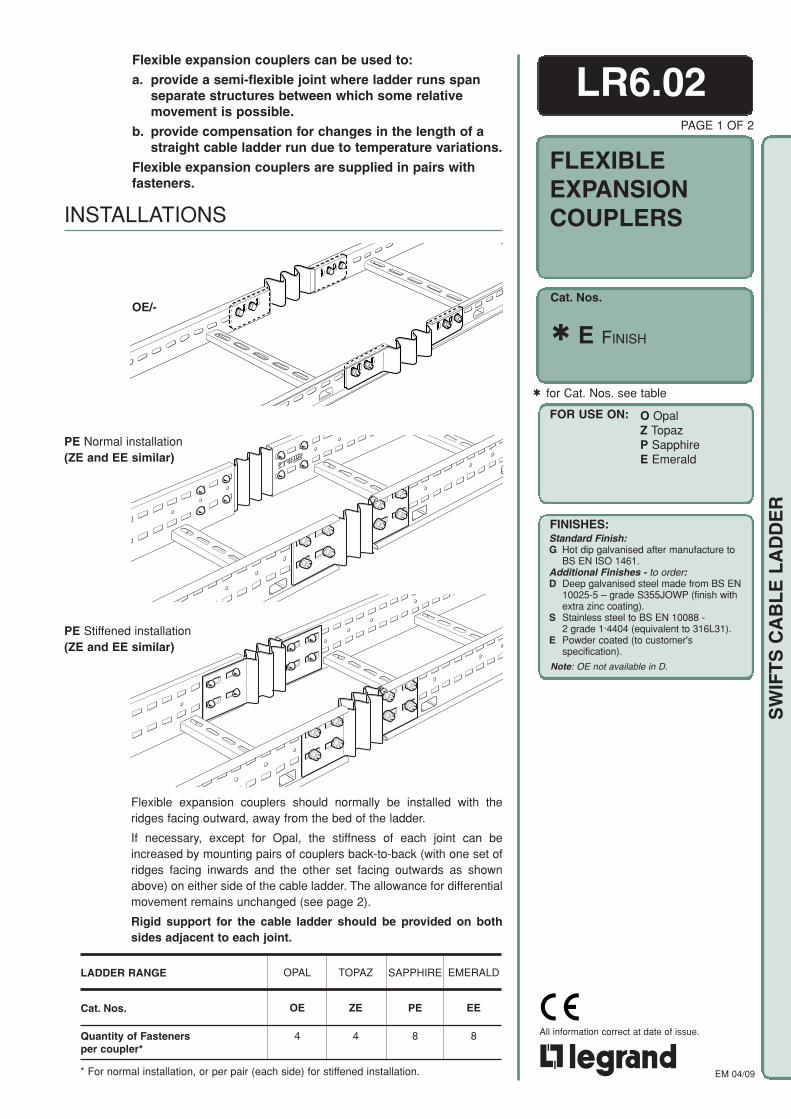
Cat. Nos.
FOR USE ON:
FINISHES:
O OpalZ TopazP SapphireE Emerald
Standard Finish:G Hot dip galvanised after manufacture to
BS EN ISO 1461.Additional Finishes - to order:D Deep galvanised steel made from BS EN
10025-5 – grade S355JOWP (finish withextra zinc coating).
S Stainless steel to BS EN 10088 -2 grade 1·4404 (equivalent to 316L31).
E Powder coated (to customer'sspecification).
EM 04/09
All information correct at date of issue.
SW
IFT
S C
AB
LE
LA
DD
ER
LR6.02
FLEXIBLEEXPANSIONCOUPLERS
PAGE 1 OF 2
INSTALLATIONS
LADDER RANGE
Cat. Nos.
Quantity of Fastenersper coupler*
OPAL
OE
4
TOPAZ
ZE
4
SAPPHIRE
PE
8
EMERALD
EE
8
* For normal installation, or per pair (each side) for stiffened installation.
for Cat. Nos. see table
Flexible expansion couplers should normally be installed with theridges facing outward, away from the bed of the ladder.
If necessary, except for Opal, the stiffness of each joint can beincreased by mounting pairs of couplers back-to-back (with one set ofridges facing inwards and the other set facing outwards as shownabove) on either side of the cable ladder. The allowance for differentialmovement remains unchanged (see page 2).
Rigid support for the cable ladder should be provided on bothsides adjacent to each joint.
PE Stiffened installation(ZE and EE similar)
E FINISH
Flexible expansion couplers can be used to:
a. provide a semi-flexible joint where ladder runs spanseparate structures between which some relativemovement is possible.
b. provide compensation for changes in the length of astraight cable ladder run due to temperature variations.
Flexible expansion couplers are supplied in pairs withfasteners.
OE/-
PE Normal installation(ZE and EE similar)
Note: OE not available in D.

EM 04/09
All information correct at date of issue.
SW
IFT
S C
AB
LE
LA
DD
ER
Finish: For ladders with G and D finishes,fasteners are high tensile Grade 8.8.For ladders with S finish, fastenersare corrosion resistant stainless GradeA470.
For ladders with E finish, the fastenersare Grade 8.8 hot dip galvanised. Analternative material for fasteners maybe required depending on the installationenvironment - contact our Sales Officefor guidance.
RecommendedTorque Setting (M10): 40Nm
DIMENSIONS & WEIGHTS
D
B
A
C
EIGHT 37 x 13RECTANGULARSLOTS
D
B
A
C
LR6.02PAGE 2 OF 2
D
B
A
C
EIGHT 37 x 13RECTANGULARSLOTS
PEEE
OEFASTENERS (included):For quantity required see table on page 1.
OE
G C D H J K
ZE, PE, EE
Cat. Nos.
0.2
0.6
1.1
1.4
D
1.0
1.0
1.5
1.5
C
80.0
113.0
111.5
111.5
B
42
84
115
138
OE
ZE
PE
EE
WEIGHTkgA
254
320
317
317
D
A
B
C
EIGHT 37 x 13RECTANGULARSLOTS
DIMENSIONSAll dimensions given are inmillimetres (mm).
WEIGHTSAll weights given are in kilograms (kg)and are for two items (one flexibleexpansion coupler set) in a hot dipgalvanised G finish.
To obtain the appropriate componentweight in other finishes, multiply thegiven weight by the following factors:
Deep Galvanised (D) x 1.07Stainless steel (S) x 0.94Powder coated (E) x 0.97
Each joint formed by flexible expansion couplers provides for up to 10mm oflinear movement between the two adjacent ladders.
To calculate the ideal distance between flexible expansion couplerinstallations, use the formula: L = KS
TWhere: L = distance between flexible expansion couplers, in metres
KS= 909 for mild steel, 962 for stainless steel.T = temperature range (in °C) for which allowance is to be made.
NOTE: Coefficients of linear expansion: mild steel = 11 x 10-6/ °Cstainless steel = 10.4 x 10⁻⁶/ °C
A D C B E FB
ASSEMBLYSPACING OF FLEXIBLE EXPANSION COUPLERS
A M6x16 setscrewsB M6 washerC Side railD CouplerE M6 shakeproof
washerF M6 nut
G M10x20 coachboltH M10 form A washerJ M10 single coil spring
washerK M10 nut
ZE
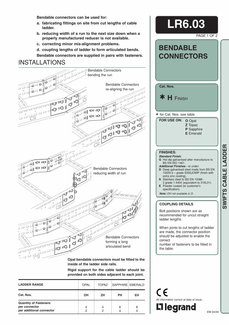
Cat. Nos.
FOR USE ON:
FINISHES:
O OpalZ TopazP SapphireE Emerald
Standard Finish:G Hot dip galvanised after manufacture to
BS EN ISO 1461.Additional Finishes - to order:D Deep galvanised steel made from BS EN
10025-5 – grade S355JOWP (finish withextra zinc coating).
S Stainless steel to BS EN 10088 -2 grade 1·4404 (equivalent to 316L31).
E Powder coated (to customer'sspecification).
EM 04/09
All information correct at date of issue.
SW
IFT
S C
AB
LE
LA
DD
ER
INSTALLATIONS
LR6.03PAGE 1 OF 2
Bendable Connectorsre-aligning the run
Bendable connectors can be used for:
a. fabricating fittings on site from cut lengths of cableladder.
b. reducing width of a run to the next size down when aproperly manufactured reducer is not available.
c. correcting minor mis-alignment problems.
d. coupling lengths of ladder to form articulated bends.
Bendable connectors are supplied in pairs with fasteners.
OPAL
OH
42
TOPAZ
ZH
42
SAPPHIRE
PH
84
EMERALD
EH
84
Bendable Connectorsreducing width of run
Bendable Connectorsforming a longarticulated bend
Opal bendable connectors must be fitted to theinside of the ladder side rails.
Rigid support for the cable ladder should beprovided on both sides adjacent to each joint.
LADDER RANGE
Cat. Nos.
Quantity of Fasteners:per connectorper additional connector
for Cat. Nos. see table
H FINISH
BENDABLECONNECTORS
Bendable Connectorsbending the run
COUPLING DETAILS
Bolt positions shown are asrecommended for uncut straightladder lengths.
When joints to cut lengths of ladderare made, the connector positionshould be adjusted to enable thecorrectnumber of fasteners to be fitted inthe table.
Note: OH not available in D.
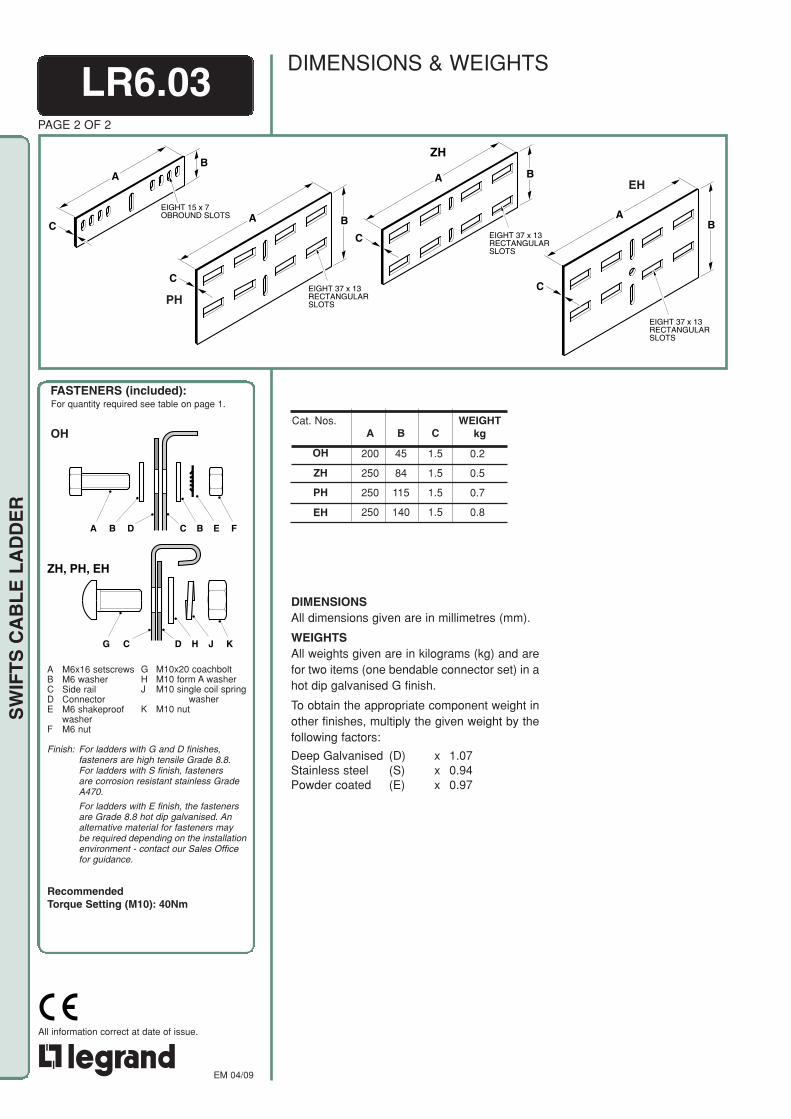
EM 04/09
All information correct at date of issue.
SW
IFT
S C
AB
LE
LA
DD
ER
Finish: For ladders with G and D finishes,fasteners are high tensile Grade 8.8.For ladders with S finish, fastenersare corrosion resistant stainless GradeA470.
For ladders with E finish, the fastenersare Grade 8.8 hot dip galvanised. Analternative material for fasteners maybe required depending on the installationenvironment - contact our Sales Officefor guidance.
RecommendedTorque Setting (M10): 40Nm
DIMENSIONS & WEIGHTSLR6.03
OH
PAGE 2 OF 2
C
A B
EIGHT 37 x 13RECTANGULARSLOTSPH
C
A B
EIGHT 37 x 13RECTANGULARSLOTS
FASTENERS (included):For quantity required see table on page 1.
OHCat. Nos.
C
1.5
1.5
1.5
1.5
B
45
84
115
140
OH
ZH
PH
EH
A
200
250
250
250
0.2
0.5
0.7
0.8
WEIGHTkg
DIMENSIONSAll dimensions given are in millimetres (mm).
WEIGHTSAll weights given are in kilograms (kg) and arefor two items (one bendable connector set) in ahot dip galvanised G finish.
To obtain the appropriate component weight inother finishes, multiply the given weight by thefollowing factors:
Deep Galvanised (D) x 1.07Stainless steel (S) x 0.94Powder coated (E) x 0.97
C
AB
EIGHT 37 x 13RECTANGULARSLOTS
EH
C
AB
EIGHT 15 x 7OBROUND SLOTS
G C D H J K
ZH, PH, EH
A D C B E FB
ZH
A M6x16 setscrewsB M6 washerC Side railD ConnectorE M6 shakeproof
washerF M6 nut
G M10x20 coachboltH M10 form A washerJ M10 single coil spring
washerK M10 nut
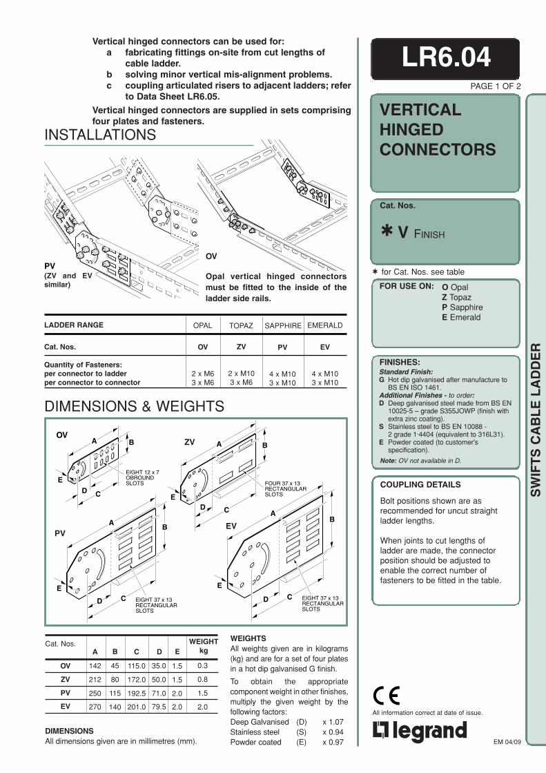
Cat. Nos.
FOR USE ON:
FINISHES:
O OpalZ TopazP SapphireE Emerald
Standard Finish:G Hot dip galvanised after manufacture to
BS EN ISO 1461.Additional Finishes - to order:D Deep galvanised steel made from BS EN
10025-5 – grade S355JOWP (finish withextra zinc coating).
S Stainless steel to BS EN 10088 -2 grade 1·4404 (equivalent to 316L31).
E Powder coated (to customer'sspecification).
EM 04/09
All information correct at date of issue.
SW
IFT
S C
AB
LE
LA
DD
ER
INSTALLATIONS
B
E
CD
FOUR 37 x 13RECTANGULARSLOTS
A
LR6.04PAGE 1 OF 2
VERTICALHINGEDCONNECTORS
Vertical hinged connectors can be used for:a fabricating fittings on-site from cut lengths of
cable ladder.b solving minor vertical mis-alignment problems.c coupling articulated risers to adjacent ladders; refer
to Data Sheet LR6.05.
Vertical hinged connectors are supplied in sets comprisingfour plates and fasteners.
DIMENSIONSAll dimensions given are in millimetres (mm).
WEIGHTkgDB
45
80
115
140
OV
ZV
PV
EV
Cat. Nos.A
142
212
250
270
0.3
0.8
1.5
2.0
E
1.5
1.5
2.0
2.0
EV
ZV
PVB
A
EEIGHT 37 x 13RECTANGULARSLOTS
CD
BA
E
EIGHT 37 x 13RECTANGULARSLOTS
CD
PV(ZV and EVsimilar)
Opal vertical hinged connectorsmust be fitted to the inside of theladder side rails.
OV
BA
EEIGHT 12 x 7OBROUNDSLOTS
CD
OV
LADDER RANGE
Cat. Nos.
Quantity of Fasteners:per connector to ladderper connector to connector
for Cat. Nos. see table
V FINISH
EMERALD
EV
4 x M103 x M10
ZV
2 x M103 x M6
TOPAZ
OV
2 x M63 x M6
OPAL
PV
4 x M103 x M10
SAPPHIRE
C
115.0
172.0
192.5
201.0
35.0
50.0
71.0
79.5
DIMENSIONS & WEIGHTS
WEIGHTSAll weights given are in kilograms(kg) and are for a set of four platesin a hot dip galvanised G finish.
To obtain the appropriatecomponent weight in other finishes,multiply the given weight by thefollowing factors:Deep Galvanised (D) x 1.07Stainless steel (S) x 0.94Powder coated (E) x 0.97
Note: OV not available in D.
COUPLING DETAILS
Bolt positions shown are asrecommended for uncut straightladder lengths.
When joints to cut lengths ofladder are made, the connectorposition should be adjusted toenable the correct number offasteners to be fitted in the table.

EM 04/09
All information correct at date of issue.
SW
IFT
S C
AB
LE
LA
DD
ER
Finish: For ladders with G and D finishes,fasteners are high tensile Grade 8.8.For ladders with S finish, fastenersare corrosion resistant stainless GradeA470.
For ladders with E finish, the fastenersare Grade 8.8 hot dip galvanised. Analternative material for fasteners maybe required depending on the installationenvironment - contact our Sales Officefor guidance.
RecommendedTorque Setting (M10): 40Nm
LR6.04PAGE 2 OF 2
CONNECTOR TO LADDERFASTENERS (included):For quantity required see table on page 1.
G C D H J K
OV
ZV, PV, EV
ASSEMBLY
45°
y:w
F:C
15°
y:v
G:C
18°
-
A:F
22.5°
-
E:B
x:u
B:G
30°
OV
ZV, PV, EV
A BC
D
EFG
H O
E F G
O HD
CB A
u vw
xyz o o z
x y
wv u
ComponentReference
OV
ZV, PV & EV
Vertical hinged connectors can either be connected together to form pre-setangles or pre-assembled for adjustment in situ.
1 Identify the correct outer fixing holes for the required pre-setangle (see table and illustration below).
2 Insert a fastener through the identified holes in both plates and fit alocking washer and nut but do not fully tighten.
Do not insert fasteners through the centre hole first, this makesidentification of the outer holes very difficult.
3 Move the two connectors to align the centre holes. Insert a fastenerthrough the holes and fit a locking washer and nut but do not fully tighten.
4 Insert a third fastener through a slot in one connector and an aligninghole in the other. Fit a locking washer and nut.
5 Tighten all fasteners.
ASSEMBLY TO A PRE-SET ANGLE
PRE-ASSEMBLY FOR ADJUSTMENT IN-SITU1 Insert a fastener through the outer hole of both connectors. Fit a locking
washer and nut and tighten sufficiently to hold the assembly togetherwhile it is carried to the installation position.
2 Fit the assembly to the installed ladders.
3 Insert a second fastener through the slot in one connector and analigning hole and fit fit a locking washer and nut.
4 If possible, insert a third fastener through either the alternate slot and analigning hole, or two aligning holes. Fit a locking washer and nut.
5 Tighten all fasteners.
A D C B E FB
CONNECTOR TO CONNECTORFASTENERS (included):For quantity required see table on page 1
A M6x16 setscrewsB M6 washerC Side railD ConnectorE M6 shakeproof
washerF M6 nut
G M10x20 coachboltH M10 form A washerJ M10 single coil spring
washerK M10 nut
A D B E FB L D H J KH
OV/-, ZV/- PV/-, EV/-OV, ZV PV, EV

Cat. Nos.
FOR USE ON:
FINISHES:
O OpalZ TopazP SapphireE Emerald
Standard Finish:G Hot dip galvanised after manufacture to
BS EN ISO 1461.Additional Finishes - to order:D Deep galvanised steel made from BS EN
10025-5 – grade S355JOWP (finish withextra zinc coating).
S Stainless steel to BS EN 10088 -2 grade 1·4404 (equivalent to 316L31).
E Powder coated (to customer'sspecification).
EM 04/09
All information correct at date of issue.
SW
IFT
S C
AB
LE
LA
DD
ER
A
245
280
315
338
Two ArticulatedRiser sectionsused as a riser
DIMENSIONS
A B
CD
BA
CD
A B
CD
OAR ZAR
PAR EAR
LR6.05PAGE 1 OF 2
ARTICULATEDRISERS
D
1.5
1.5
2.0
2.0
Cat. Nos.
OAR
ZAR
PAR
EAR
B
50
90
127
150
200
200
200
200
C
All dimensions given are inmillimetres (mm).
One or more articulated riser sets can be used to solvemost mis-alignment problems on site.
Each set comprises three articulated riser sections, thenecessary vertical hinged connectors and fasteners.
Articulated risers are available with all rung options, refer toData Sheet LR7.01.
Articulated Riser Setbridging obstructions on site
LADDER RANGE
Cat. Nos.
Quantity of Fastenersper riser to riser joint
Opal vertical hinged connectors must be fitted to the inside ofthe ladder side rails.
Rigid support for the cable ladder should be provided on bothsides adjacent to each vertical hinged connector joint.
OPAL
OAR
3 x M6
TOPAZ
ZAR
3 x M6
SAPPHIRE
PAR
3 x M10
EMERALD
EAR
3 x M10
The quantity of fasteners for vertical hinged connectors is given in Data Sheet LR6.04.
W = ladder width
for Cat. Nos. see table
AR W FINISH
AB
CD
Note: OAR not available in D.
INSTALLATIONS

SW
IFT
S C
AB
LE
LA
DD
ER
900LR6.05
PAGE 2 OF 2 -
1.8
2.4
2.8
750
-
1.6
2.2
2.6
600
0.7
1.3
1.9
2.3
450
0.6
1.1
1.8
2.1
0.5
1.0
1.6
2.0
300225
0.5
-
-
-
150
0.4
0.8
1.5
1.8
100
0.4
-
-
-
OAR
ZAR
PAR
EAR
Cat. Nos.
WEIGHTS
RISER TO RISER FASTENERS(included): For quantity required see table on page 1.
A C B D EB F C G H JG
OAR/-, ZAR/- PAR/-, EAR/- A M6x16 setscrewB M6 washerC Side railsD M6 shakeproof washerE M6 nutF M10x20 setscrewG M10 form A washerH M10 single coil spring
washerJ M10 nut
All weights given are in kilograms (kg) and are for a singlearticulated riser section in a hot dip galvanised G finish.
To obtain the appropriate component weight in other finishes,multiply the given weight by the following factors:
Deep Galvanised (D) x 1.07Stainless steel (S) x 0.94Powder coated (E) x 0.97
Recommended Torque Setting (M10): 40NmFinish:For ladders with G and D finishes,fasteners are high tensile Grade 8.8.For ladders with S finish, fasteners arecorrosion resistant stainless GradeA470.
For ladders with E finish, the fastenersare Grade 8.8 hot dip galvanised. Analternative material for fasteners may berequired depending on the installationenvironment - contact our Sales Officefor guidance.
OAR, ZAR PAR, EAR
EM 04/09
All information correct at date of issue.
OAR
ZAR, PAR, EAR
y:w
F:C
15°
y:v
G:C
18°
-
A:F
22.5°
-
E:B
x:u
B:G
OAR
ZAR, PAR, EAR
45°30°Cat. Nos.
SECTION REQUIRED FOR A GIVEN ANGLE
RAD.240
RAD.370
RAD.500
RAD.630
RAD.760
1 2 3 4 5
y:w x:uB:G
E:BA:F y:v
G:CRAD.370 RAD.
760
90°
60°x:uB:G
y:vG:C
45°RAD.500 RAD.
760
E:By:vG:C
30°RAD.760
y:vG:C
ASSEMBLY TO A PRE-SET ANGLE AND RADIUSThe diagrams alongside show the number of articulated risersections needed to form a given angle and radius.1 Identify the correct fixing holes.2 Stand each component part on its side in its assembled
position, overlapping the joint alternately. At every upperjoint insert a fastener through the identified outer holes but
do not fully tighten.Do not insert fasteners through the centre hole first, thismakes identification of the outer holes very difficult.
3 Adjust the assembly to align the centre holes of each joint. Fitfasteners but do not fully tighten.
4 At each joint, insert a third fastener through the slot andcorresponding hole.
5 Tighten all fasteners.6 Turn the whole assembly over and repeat steps 1 to 5.
Articulated riser sets can be connected to form either pre-setangles and radii or pre-assembled for adjustment in-situ.
For fixing vertical hinged connectors to ladder refer to Data SheetLR6.04.
ASSEMBLY
A BC
D
EFG
H O
E F G
O HD
CB A
u vw
xyz o o z
x y
wv u
1 Lay out the required number or articulated riser sections andvertical hinged connectors, overlapping each joint alternately asshown on page 1.
2 At each joint align the centre holes in each component andinsert a fastener sufficiently tight to hold the assembly togetherand carry it to the installation position.
3 Fit the vertical hinged connectors to the ladder - refer to DataSheet LR6.04.
4 Adjust the position of each section until the desired path isachieved and tighten the centre fastener at each joint.
5 Insert two additional fasteners at each joint and tighten allfasteners.
PRE-ASSEMBLY FOR ADJUSTMENT IN-SITU
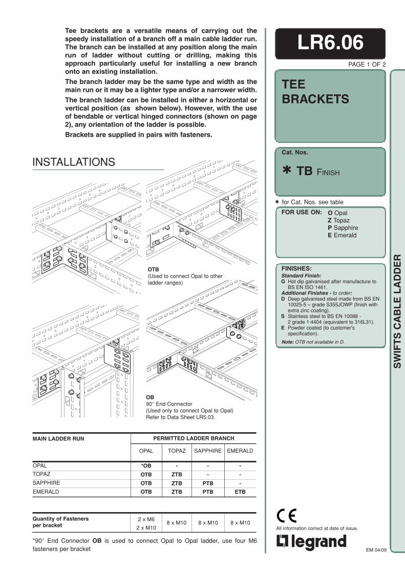
Cat. Nos.
FOR USE ON:
FINISHES:
O OpalZ TopazP SapphireE Emerald
Standard Finish:G Hot dip galvanised after manufacture to
BS EN ISO 1461.Additional Finishes - to order:D Deep galvanised steel made from BS EN
10025-5 – grade S355JOWP (finish withextra zinc coating).
S Stainless steel to BS EN 10088 -2 grade 1·4404 (equivalent to 316L31).
E Powder coated (to customer'sspecification).
EM 04/09
All information correct at date of issue.
SW
IFT
S C
AB
LE
LA
DD
ER
8 x M10
LR6.06PAGE 1 OF 2
TEEBRACKETS
PERMITTED LADDER BRANCHMAIN LADDER RUN
OPAL
TOPAZ
SAPPHIRE
EMERALD
Quantity of Fastenersper bracket 8 x M10 8 x M10
TOPAZ
-
ZTB
ZTB
ZTB
SAPPHIRE
-
-
PTB
PTB
EMERALD
-
-
-
ETB
Tee brackets are a versatile means of carrying out thespeedy installation of a branch off a main cable ladder run.The branch can be installed at any position along the mainrun of ladder without cutting or drilling, making thisapproach particularly useful for installing a new branchonto an existing installation.
The branch ladder may be the same type and width as themain run or it may be a lighter type and/or a narrower width.
The branch ladder can be installed in either a horizontal orvertical position (as shown below). However, with the useof bendable or vertical hinged connectors (shown on page2), any orientation of the ladder is possible.
Brackets are supplied in pairs with fasteners.
for Cat. Nos. see table
TB FINISH
2 x M6
2 x M10
*90° End Connector OB is used to connect Opal to Opal ladder, use four M6fasteners per bracket
INSTALLATIONS
OTB(Used to connect Opal to otherladder ranges)
OB90° End Connector(Used only to connect Opal to Opal)Refer to Data Sheet LR5.03.
OPAL
*OB
OTB
OTB
OTB
Note: OTB not available in D.

EM 04/09
All information correct at date of issue.
SW
IFT
S C
AB
LE
LA
DD
ER Finish: For ladders with G and D finishes,
fasteners are high tensile Grade 8.8.For ladders with S finish, fastenersare corrosion resistant stainless GradeA470.
For ladders with E finish, the fastenersare Grade 8.8 hot dip galvanised. Analternative material for fasteners maybe required depending on the installationenvironment - contact our Sales Officefor guidance.
RecommendedTorque Setting (M10): 40Nm
C
A
D
B
SIXTEEN 12 x 7OBROUND SLOTS
A C D B E FB
FASTENERS (included):For quantity required see table on page 1.
G C D H J K
ZTB, PTB, ETB
PAGE 2 OF 2
Important:Rigid support for the main ladder runshould be provided immediately adjacentto the installed position of the branch. Thecable loading on the branch should betreated as a point load applied unevenly tothe main ladder run and the implications ofthis must be properly considered.
Tee Brackets used withBendable Connectors
DIMENSIONSAll dimensions given are in millimetres (mm).
WEIGHTSAll weights given are in kilograms (kg) and arefor two items (one tee bracket set) in a hot dipgalvanised G finish.
To obtain the appropriate component weight inother finishes, multiply the given weight by thefollowing factors:
Deep Galvanised (D) x 1.07Stainless steel (S) x 0.94Powder coated (E) x 0.97
Tee Brackets used withVertical Hinged Connectors
WEIGHTkg
0.3
0.5
0.5
1.0
1.0
Cat. Nos.
OB
OTB
ZTB
PTB
ETB
Tee brackets when used with bendable or vertical hingedconnectors are an economical and fast way of coping withunforeseen problems as they arise during installation. Eachcomponent reference covers one complete set of two bracketsand the required fasteners.
OB, OTB
PTB and ETB
C
A
D
B
SIXTEEN 37 x 13RECTANGULARSLOTS
C
A
D
B
FOUR 37 x 13RECTANGULARSLOTS
FIFTEEN 15 x 7OBROUND SLOTS
OTB
C
A
D
B
TEN 37 x 13RECTANGULARSLOTS
OB
A M6x16 setscrewsB M6 washerC Side railD BracketE M6 shakeproof
washer
F M6 nutG M10x20 coachboltH M10 form A washerJ M10 single coil spring
washerK M10 nut
ZTB
A
100
125
125
125
125
B
100
125
125
155
155
C
2.0
2.0
2.0
3.0
3.0
D
45
78
78
103
103
DIMENSIONS & WEIGHTS
LR6.06
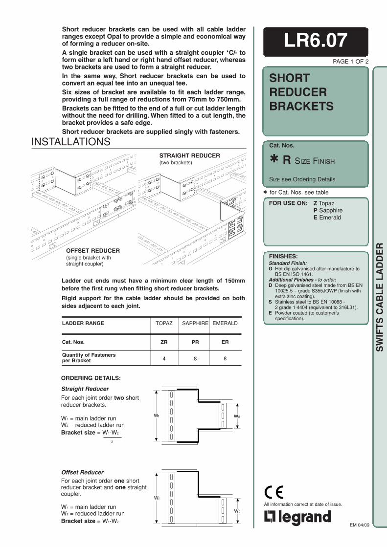
Cat. Nos.
FOR USE ON:
FINISHES:
O OpalZ TopazP SapphireE Emerald
Standard Finish:G Hot dip galvanised after manufacture to
BS EN ISO 1461.Additional Finishes - to order:D Deep galvanised steel made from BS EN
10025-5 – grade S355JOWP (finish withextra zinc coating).
S Stainless steel to BS EN 10088 -2 grade 1·4404 (equivalent to 316L31).
E Powder coated (to customer'sspecification).
EM 04/09
All information correct at date of issue.
SW
IFT
S C
AB
LE
LA
DD
ER
W2
W1
Offset ReducerFor each joint order one shortreducer bracket and one straightcoupler.
W1 = main ladder runW2 = reduced ladder runBracket size = W1-W2
ORDERING DETAILS:
Straight Reducer
For each joint order two shortreducer brackets.
W1 = main ladder runW2 = reduced ladder runBracket size = W1-W2
2
Ladder cut ends must have a minimum clear length of 150mmbefore the first rung when fitting short reducer brackets.
Rigid support for the cable ladder should be provided on bothsides adjacent to each joint.
LR6.07PAGE 1 OF 2
SHORTREDUCERBRACKETS
for Cat. Nos. see table
SIZE see Ordering Details
R SIZE FINISH
Short reducer brackets can be used with all cable ladderranges except Opal to provide a simple and economical wayof forming a reducer on-site.A single bracket can be used with a straight coupler *C/- toform either a left hand or right hand offset reducer, whereastwo brackets are used to form a straight reducer.In the same way, Short reducer brackets can be used toconvert an equal tee into an unequal tee.Six sizes of bracket are available to fit each ladder range,providing a full range of reductions from 75mm to 750mm.Brackets can be fitted to the end of a full or cut ladder lengthwithout the need for drilling. When fitted to a cut length, thebracket provides a safe edge.Short reducer brackets are supplied singly with fasteners.
LADDER RANGE
Cat. Nos.
Quantity of Fastenersper Bracket
TOPAZ
ZR
4
SAPPHIRE
PR
8
EMERALD
ER
8
OFFSET REDUCER(single bracket withstraight coupler)
INSTALLATIONSSTRAIGHT REDUCER(two brackets)
Z TopazP SapphireE Emerald
W1 W2
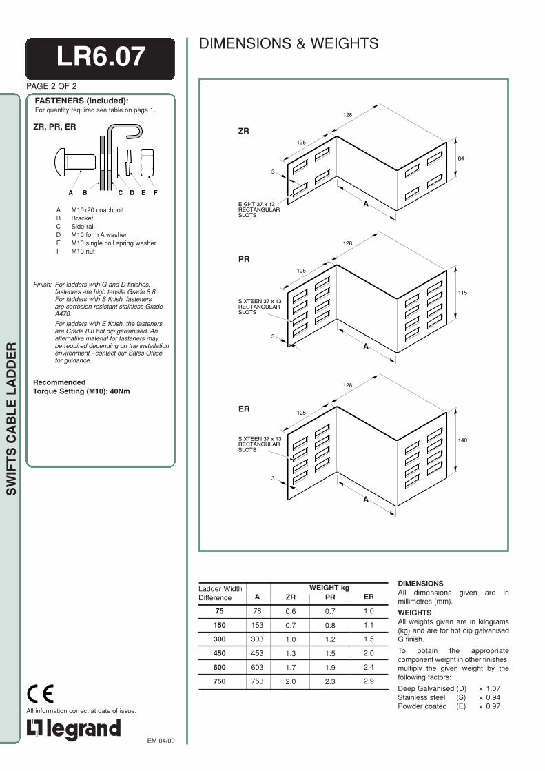
EM 04/09
All information correct at date of issue.
SW
IFT
S C
AB
LE
LA
DD
ER
Finish: For ladders with G and D finishes,fasteners are high tensile Grade 8.8.For ladders with S finish, fastenersare corrosion resistant stainless GradeA470.
For ladders with E finish, the fastenersare Grade 8.8 hot dip galvanised. Analternative material for fasteners maybe required depending on the installationenvironment - contact our Sales Officefor guidance.
RecommendedTorque Setting (M10): 40Nm
PR
0.7
0.8
1.2
1.5
1.9
2.3
A
78
153
303
453
603
753
ZR
0.6
0.7
1.0
1.3
1.7
2.0
ER
1.0
1.1
1.5
2.0
2.4
2.9
LR6.07PAGE 2 OF 2
FASTENERS (included):For quantity required see table on page 1.
A
125
128
140
3
SIXTEEN 37 x 13RECTANGULARSLOTS
125
128
84
A
3
EIGHT 37 x 13RECTANGULARSLOTS
A
125
128
115
3
SIXTEEN 37 x 13RECTANGULARSLOTS
PR
ZR
ER
Ladder WidthDifference
75
150
300
450
600
750
WEIGHT kg DIMENSIONSAll dimensions given are inmillimetres (mm).
WEIGHTSAll weights given are in kilograms(kg) and are for hot dip galvanisedG finish.
To obtain the appropriatecomponent weight in other finishes,multiply the given weight by thefollowing factors:
Deep Galvanised (D) x 1.07Stainless steel (S) x 0.94Powder coated (E) x 0.97
ZR, PR, ER
DIMENSIONS & WEIGHTS
A B C D E F
A M10x20 coachboltB BracketC Side railD M10 form A washerE M10 single coil spring washerF M10 nut

Cat. Nos.
FOR USE ON:
FINISHES:
EM 04/09
All information correct at date of issue.
SW
IFT
S C
AB
LE
LA
DD
ER
Straight dividers are used, along with curved dividers, tophysically separate different types or groups of cablewithin one cable ladder run.
They are supplied in 3.0m lengths with fasteners.PAGE 1 OF 2
for Cat. Nos. see table
DIMENSIONSAll dimensions given are inmillimetres (mm).
WEIGHTSAll weights given are inkilograms (kg).
Straight dividers with G finish are for use on ladder runs with G or D finishes.
TOPAZ, SAPPHIRE & EMERALD:G, S and E finishesOPAL: S finish
A3000
35
t
WITHOUTRETURNFLANGE
3000A
35
t
WITHRETURNFLANGE
OPAL: G finish
DIMENSIONS & WEIGHTS
INSTALLATION
O OpalZ TopazP SapphireE Emerald
LR6.08
DV FINISH
LADDERSTRAIGHTDIVIDERS
EMERALD
EDV
10
SAPPHIRE
PDV
10
TOPAZ
ZDV
10
OPAL
ODV
10
LADDER RANGE
Cat. Nos.
Quantity of Fastenersper 3.0m length
G
2.2
4.1
6.7
7.7
S
2.6
3.9
6.3
7.2
Cat. Nos.
ODV
ZDV
PDV
EDV
A
27
67
92
112
t
1.5
1.5
2.0
2.0
WEIGHT kg
For quantity required see table above left.
DV G and DV EM6x12 roofing boltM6 nutM6 roofing washers (2 off)
DV SM6x12 pan head screwM6 form A washerM6 square washerM6 nut
FASTENERS (included):
FINISHES:Standard Finish:G Hot dip galvanised after manufacture to
BS EN ISO 1461.Additional Finishes - to order:D Deep galvanised steel made from BS EN
10025-5 – grade S355JOWP (finish withextra zinc coating).
S Stainless steel to BS EN 10088 -2 grade 1·4404 (equivalent to 316L31).
E Powder coated (to customer'sspecification).
E
2.2
4.1
6.7
7.7
Finish: For ladders with G and D finishes,fasteners are galvanised or zinc plated.For ladders with S finish, fasteners arecorrosion resistant stainless Grade A4.For ladders with E finish, the choice ofmaterial for fasteners will depend on theinstallation environment - contactour Sales Office for guidance.
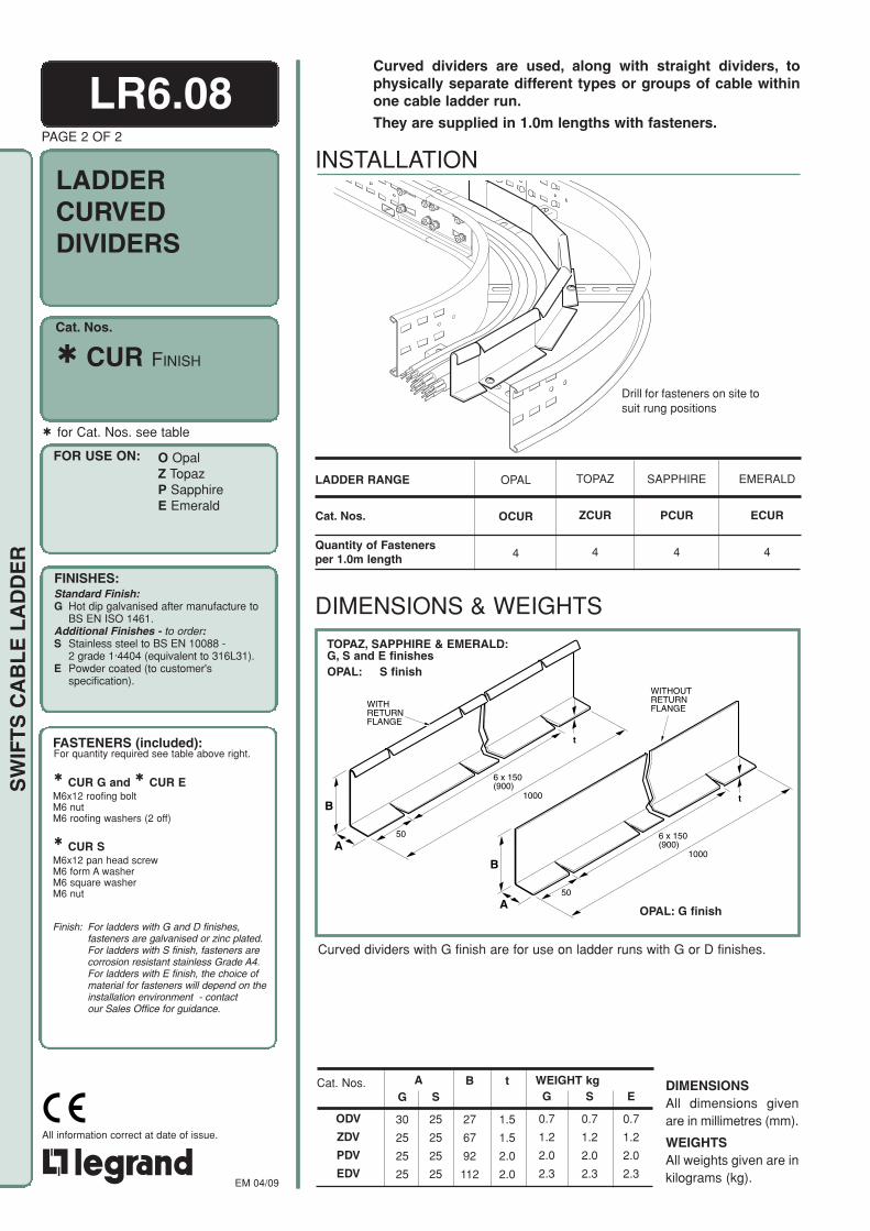
Cat. Nos.
FOR USE ON:
FINISHES:
EM 04/09
All information correct at date of issue.
SW
IFT
S C
AB
LE
LA
DD
ER
for Cat. Nos. see table
PAGE 2 OF 2
INSTALLATION
LADDER RANGE
Cat. Nos.
Quantity of Fastenersper 1.0m length
DIMENSIONS & WEIGHTS
Curved dividers with G finish are for use on ladder runs with G or D finishes.
1000B
t
A50
6 x 150(900)
WITHRETURNFLANGE
1000B
t
A50
6 x 150(900)
WITHOUTRETURNFLANGE
Drill for fasteners on site tosuit rung positions
O OpalZ TopazP SapphireE Emerald
Curved dividers are used, along with straight dividers, tophysically separate different types or groups of cable withinone cable ladder run.
They are supplied in 1.0m lengths with fasteners.
CUR FINISH
LR6.08
TOPAZ, SAPPHIRE & EMERALD:G, S and E finishesOPAL: S finish
LADDERCURVEDDIVIDERS
S
0.7
1.2
2.0
2.3
Cat. Nos.
ODV
ZDV
PDV
EDV
WEIGHT kgG
0.7
1.2
2.0
2.3
t
1.5
1.5
2.0
2.0
S
25
25
25
25
G
30
25
25
25
A B
27
67
92
112
DIMENSIONSAll dimensions givenare in millimetres (mm).
WEIGHTSAll weights given are inkilograms (kg).
EMERALD
ECUR
4
TOPAZ
ZCUR
4
SAPPHIRE
PCUR
4
OPAL
OCUR
4
OPAL: G finish
FASTENERS (included):For quantity required see table above right.
CUR G and CUR EM6x12 roofing boltM6 nutM6 roofing washers (2 off)
CUR SM6x12 pan head screwM6 form A washerM6 square washerM6 nut
Finish: For ladders with G and D finishes,fasteners are galvanised or zinc plated.For ladders with S finish, fasteners arecorrosion resistant stainless Grade A4.For ladders with E finish, the choice ofmaterial for fasteners will depend on theinstallation environment - contactour Sales Office for guidance.
FINISHES:Standard Finish:G Hot dip galvanised after manufacture to
BS EN ISO 1461.Additional Finishes - to order:S Stainless steel to BS EN 10088 -
2 grade 1·4404 (equivalent to 316L31).E Powder coated (to customer's
specification).
E
0.7
1.2
2.0
2.3

Cat. Nos.
FOR USE ON:
FINISHES:Standard Finish:G Hot dip galvanised after manufacture to
BS EN ISO 1461.Additional Finishes - to order:D Deep galvanised steel made from BS EN
10025-5 – grade S355JOWP (finish withextra zinc coating).
S Stainless steel to BS EN 10088 -2 grade 1·4404 (equivalent to 316L31).
E Powder coated (to customer'sspecification).
EM 04/09
All information correct at date of issue.
SW
IFT
S C
AB
LE
LA
DD
ER
PAGE 1 OF 3
W= ladder width
One cover design is suitable for use with Topaz, Sapphireand Emerald ladder ranges.
They can be installed either resting directly on the ladderside rails (closed covers) or raised above the side railsproviding a gap for air to escape (ventilated covers).
Covers up to 450mm wide have a flat top surface and aresimply butt-jointed together. Covers 600mm wide andabove are overlapped and bolted together to increase theirrigidity. Covers 750 and 900mm wide have a stiffener fittedalong the joint for added rigidity.
All covers are 3m long and supplied with four cover clipsand associated fasteners.
V
600 wide and above:overlap joint for rigidity.
Up to 450 wide
VENTILATED COVER INSTALLATIONS
Up to 450 wide
600 wide and above:overlap joint for rigidity.
LR6.09
Z TopazP SapphireE Emerald
CV W FINISH
CLOSED COVER INSTALLATIONS
COVERS FORCABLE LADDERSTRAIGHTLENGTHS
750 & 900 wide
Covers can not be used whenhanger rod brackets are fitted toladder.

EM 04/09
All information correct at date of issue.
SW
IFT
S C
AB
LE
LA
DD
ER
Clips are fitted to the inside of bothcover side flanges as shown; the endclips provide anchorage for the joinedends of adjacent covers.
CLIPS
Before fitting the covers ensure aminimum clearance of 30mmbetween the ladder and the verticalsupport face. For access to fit coverclips a larger clearance is requiredwhen the vertical support is a solidface. Refer to Data Sheet LR5.01 forfurther details.
ASSEMBLY
CLOSED COVERS
Place each cover over the ladder siderails and push the clip under the siderail return flanges before fitting andtightening the fasteners.
VENTILATED COVERS
Slide the clips over the top returnflange of the ladder side rails and placethe cover over the clips. Fit and tightenthe fasteners.
WIDE COVERS-600mm AND ABOVE
LR6.09COVER CLIP POSITIONS
PAGE 2 OF 3
30mm (min)
COVER
CLIP
SIDE RAIL
25mm
CLIP
SIDE RAIL
COVER
A B C D E F G
COVER CLIP(two fasteners per clip)
OVERLAP JOINT ON 600 WIDE(two fasteners per joint)
H J K H
LMN
(four fasteners per joint)
H J K H
LM
OVERLAP JOINT ON 750 & 900 WIDE
600mm wide coversFor wider covers with overlappedjoints, fit the first cover as above. Pushthe 'U' shaped retaining nuts over theholes in the overlap tongue. Fit thesecond cover with its straight endoverlapping the tongue on the firstcover. Insert fasteners and secure.
700 and 900mm wide coversFor covers fitted with a stiffener,assemble the covers as describedabove and place the stiffener on to thetop cover along the joint. Insertfasteners and secure.
'U'-SHAPEDRETAININGNUT
FIRST COVER
SECOND COVER
'U'-SHAPED RETAINING NUT
FIRST COVER
SECOND COVER
STIFFENER
A CoverB Side railC Cover clipD M8 nutE M8 form A washerF Spring washerG M8x16 setscrewH CoverJ 'U'-shape retaining nutK M6x16 setscrewL M6 form A washerM Spring washerN Stiffener
Finish: For covers with G and D finishes,fasteners are high tensile Grade 8.8except for retaining nut which is'Dacromet' coated. For covers with Sfinish, fasteners are corrosion resistantstainless Grade A470, except forretaining nut which is 'Xylan' coated.For covers with E finish, the fastenersare Grade 8.8 hot dip galvanised. Analternative material for fasteners maybe required depending on theinstallation environment - contactour Sales Office for guidance.
FASTENERS (included):

Cat. Nos.
FOR USE ON:
FINISHES:Standard Finish:G Hot dip galvanised after manufacture to
BS EN ISO 1461.Additional Finishes - to order:D Deep galvanised steel made from BS EN
10025-5 – grade S355JOWP (finish withextra zinc coating).
S Stainless steel to BS EN 10088 -2 grade 1·4404 (equivalent to 316L31).
E Powder coated (to customer'sspecification).
EM 04/09
All information correct at date of issue.
SW
IFT
S C
AB
LE
LA
DD
ER
LADDERWIDTH
150
300
450
600
750
900
COVERWIDTH
232
382
532
682
832
982
WEIGHTkg
11.0
16.6
22.2
28.0
33.6
39.3
DIMENSIONSAll dimensions given are in millimetres (mm).
WEIGHTSAll weights given are in kilograms (kg) and arefor hot dip galvanised G finish.
To obtain the appropriate component weight inother finishes, multiply the given weight by thefollowing factors:
Deep Galvanised (D) x 1.07Stainless steel (S) x 0.94Powder coated (E) x 0.97
Weight: 0.5 kg per 4 clips
COVER CLIP DIMENSIONS & WEIGHTS
TOPTOPTOP
44
96
38
TWO 13 x 9.5OBROUNDSLOTS
2
50
24
LR6.09COVERS DIMENSIONS & WEIGHTS
Z TopazP SapphireE Emerald
CV W FINISH
W= ladder width
PAGE 3 OF 3
COVERS FORCABLE LADDERSTRAIGHTLENGTHS
Widths 750 and 900 havetwo additional 18 x 8 slotsand Ø9.5 holes to acceptstiffener for added rigidity.
COVERWIDTH
35
3000
1.5
600-900LADDER WIDTH
150-450LADDER WIDTH
COVERWIDTH
3000
35
1.5
EIGHT 13 x 9.5OBROUND SLOTSFOR COVER CLIPS
TWO Ø 9.5HOLES
TWO 18 x 8SLOTS
EIGHT13 x 9.5OBROUNDSLOTSFOR COVERCLIPS

Cat. Nos.
FOR USE ON:
FINISHES:Standard Finish:G Hot dip galvanised after manufacture to
BS EN ISO 1461.Additional Finishes - to order:D Deep galvanised steel made from BS EN
10025-5 – grade S355JOWP (finish withextra zinc coating).
S Stainless steel to BS EN 10088 -2 grade 1·4404 (equivalent to 316L31).
E Powder coated (to customer'sspecification).
EM 04/09
All information correct at date of issue.
SW
IFT
S C
AB
LE
LA
DD
ER
CLOSED COVER INSTALLATION600 wide and above:interlock joint for rigidity.
Up to 450 wide
VENTILATED COVER INSTALLATION
LR6.10PAGE 1 OF 2
SAPPHIRE
PIRC
PIRV
PORC
PORV
EMERALD
EIRC
EIRV
EORC
EORV
TOPAZ
ZIRC
ZIRV
ZORC
ZORV
Cat. Nos.INSIDERISERS
COVER DIMENSIONS & WEIGHTSFor information on dimensions and weights for specific fitting covers, contact ourSales Office.
Closed Covers
Ventilated CoversCat. Nos.OUTSIDE
RISERS
Closed Covers
Ventilated Covers
INSIDE & OUTSIDE RISERS
LADDER RANGE
Covers are supplied to fit all fittings in the Topaz, Sapphire andEmerald cable ladder ranges.
They can be installed either resting directly on the fitting side rails(closed covers) or raised above the side rails providing an air gap(ventilated covers).
Covers for fittings up to 450mm wide are simply butt-jointedtogether. Covers 600mm wide and above are overlapped andbolted together to increase their rigidity. Covers 750 and 900mmwide have a stiffener fitted along the joint for added rigidity.
All covers are supplied with the appropriate number of fasteners.
The ordering code for fitting covers (except risers) should be completed with theinclusion of the fitting reference where indicated.
Example: A Topaz 90° flat bend cover, 300 wide, 300 radius in a hot dip galvanisedfinish- FBCV 300 90 300 G
Cover Code is based on fittingscode. Remove first letter of fittingscode (Z, P or E) and insert CVbefore remainder of number ref.eg fittings codePFB 300 90 300 Gcover codeFBCV 300 90 300 G
(except Risers)
Cat. Nos. (Risers) SEE TABLE
Z TopazP SapphireE Emerald750 & 900 wide
COVERS FORCABLE LADDERFITTINGS
Covers can not be used whenhanger rod brackets are fitted toladder.

EM 04/09
All information correct at date of issue.
SW
IFT
S C
AB
LE
LA
DD
ER
COVER CLIP POSITIONSClips are fitted to the inside of cover side flanges as shown; the end clips provideanchorage for the joined ends of adjacent covers.
FASTENERS (included):
FLAT BENDCOVER
TEECOVER
4-WAY CROSSPIECECOVER
REDUCERCOVER
RISERCOVER
Cover clips
LR6.10PAGE 2 OF 2
CLOSED COVERSTo fit covers as closed, fit the cover over thefitting side rails and place the cover clips inposition under the side rail return flanges.Fit and tighten the fasteners.
VENTILATED COVERSTo fit the covers as ventilated, slide the clipsover the top return flanges of the side railsand place the cover over the clips. Fit andtighten the fasteners.
JOINING COVERSWhen wide (600mm or over) covers arefitted, the fitting cover may join to either endof a straight length cover.
If the straight cover has an overlap tongue,push 'U'-shaped retaining nuts over theholes in the tongue. Fit the fitting cover inposition overlapping the tongue. Insertfasteners through both covers and theretaining nuts and tighten the fasteners.
For 750 and 900mm wide covers place thestiffener on to the top cover along the jointbefore inserting the fasteners.
If the straight cover has not got an overlaptongue, fit four 'U'-shaped retaining nutsover the holes in a joint strip and positionthe strip under the butt-join betweencovers. Insert fasteners through each coverand the two aligning holes in the joint stripand tighten the fasteners.
For fitting a stiffener (covers 750 and900mm wide) refer to paragraph above.
NOTE: It may be necessary to drill holesin the straight cover if it hasbeen cut to length.
COVER
CLIP
SIDE RAIL
25mm
CLIP
SIDE RAIL
COVER
45
350
250FOUR 12 x 7OBROUND SLOTS
DRILLEDHOLES
JOINTSTRIP
EXISTINGSLOTS
'U'-SHAPEDRETAININGNUT
FIRST COVER
SECOND COVER
'U'-SHAPED RETAINING NUT
FIRST COVER
SECOND COVER
STIFFENER
ASSEMBLY
COVER CLIP DIMENSIONS & WEIGHTSRefer to Data Sheet LR6.09 (page 3) for cover clip dimensionsand weights.
A B C D
H J K P
E F G
COVER CLIP(two fasteners per clip)
OVERLAP JOINT ON 600 WIDE(two fasteners per joint)
JOINT STRIP(four fasteners per joint)
H J K H
LMN
(four fasteners per joint)
H J K H
LM
LM
LM
HJK
OVERLAP JOINT ON 750 & 900 WIDE
A CoverB Side railC Cover clipD M8 nutE M8 form A
washerF Spring washerG M8x16 setscrew
H CoverJ 'U'-shape
retaining nutK M6x16 setscrewL M6 form A washerM Spring washerN StiffenerP Joint strip
Finish: For covers with G and D finishes,fasteners are high tensile Grade 8.8except for retaining nut which is'Dacromet' coated. For covers with Sfinish, fasteners are corrosionresistant stainless Grade A470, exceptfor retaining nut which is 'Xylan' coated.For covers with E finish, the fastenersare Grade 8.8 hot dip galvanised. Analternative material for fasteners maybe required depending on theinstallation environment - contactour Sales Office for guidance.
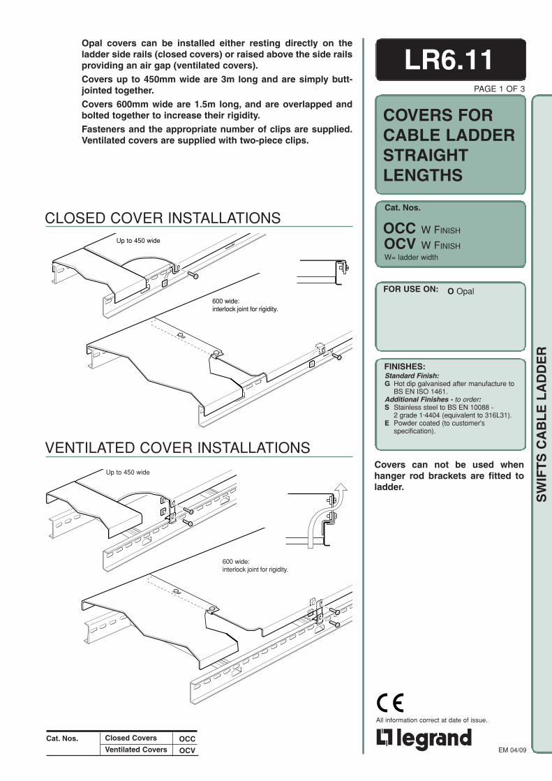
Cat. Nos.
FOR USE ON:
FINISHES:
EM 04/09
All information correct at date of issue.
SW
IFT
S C
AB
LE
LA
DD
ER
Cat. Nos.
Up to 450 wide
600 wide:interlock joint for rigidity.
Up to 450 wide
600 wide:interlock joint for rigidity.
VENTILATED COVER INSTALLATIONS
CLOSED COVER INSTALLATIONS
LR6.11Opal covers can be installed either resting directly on theladder side rails (closed covers) or raised above the side railsproviding an air gap (ventilated covers).
Covers up to 450mm wide are 3m long and are simply butt-jointed together.
Covers 600mm wide are 1.5m long, and are overlapped andbolted together to increase their rigidity.
Fasteners and the appropriate number of clips are supplied.Ventilated covers are supplied with two-piece clips.
W= ladder width
OCC W FINISH
OCV W FINISH
O Opal
PAGE 1 OF 3
COVERS FORCABLE LADDERSTRAIGHTLENGTHS
Closed Covers
Ventilated CoversOCC
OCV
Standard Finish:G Hot dip galvanised after manufacture to
BS EN ISO 1461.Additional Finishes - to order:S Stainless steel to BS EN 10088 -
2 grade 1·4404 (equivalent to 316L31).E Powder coated (to customer's
specification).
Covers can not be used whenhanger rod brackets are fitted toladder.

EM 04/09
All information correct at date of issue.
SW
IFT
S C
AB
LE
LA
DD
ER
COVER CLIP POSITIONS
CLIPS
ASSEMBLYBefore fitting the covers ensure aclearance of 15mm between theladder and the vertical support face.For access to fit cover clips a largerclearance is required when thevertical support is a solid face. Referto Data Sheet TY6.01.
When two covers 600mm wide andabove are joined together, the tongueon one cover locates in the joggle plateon the other to form an interlock joint.
Cover clips are spaced evenly along thesides of the cover, four on each side of3.0m lengths and three on each side of1.5m lengths.
CLOSED COVERS
Place each cover over the ladder siderails and place the clips in position underthe side rail return flanges before fittingand tightening the fasteners.
VENTILATED COVERS
Fit the extension cover clips to the coverand place the cover over the ladder withthe clips resting on top of the side rails.Locate the standard cover clips under theside rail top flanges in line with theextension clips. Fit and tighten thefasteners to secure the two clips together.
COVERS - 600mm wide
For 600mm wide covers with interlockjoints, fit the first cover as above. Pushthe 'U' shaped retaining nuts over theholes in the overlap tongue. Fit thesecond cover with its straight endoverlapping the tongue on the first cover.Insert fasteners and secure.
PAGE 2 OF 3
LR6.11
15mm (min)
/S G CC G
SIDE RAIL
COVER
CLIP
SIDE RAIL
70 mmCOVER
STANDARDCLIP
VENTILATEDCOVERCLIP
'U'-SHAPEDRETAININGNUT
FIRST COVER
SECOND COVER
FASTENERS (included):
ABC D
F
VENTILATEDCOVER
A
BD
C
CLOSEDCOVER
E
(one fastenerper clip)
(two fastenersper clip)
A M6x12 roofing boltB Cover clip (standard)C M6 square nutD Side railE CoverF Cover clip (extension)
OVERLAP JOINT ON 600 WIDE(two fasteners per joint)
J K L J
GH
G M6 form A washerH Spring washerJ CoverK 'U'-shape retaining nutL M6x16 setscrew
Finish: For covers with G finish, fasteners aregalvanised or zinc plated, except forretaining nut which is 'Dacromet'coated. For covers with S finish,fasteners are stainless steel except forretaining nut which is 'Xylan' coated. Forcovers with E finish, the fasteners areGrade 8.8 hot dip galvanised. Analternative material for fasteners maybe required depending on theinstallation environment - contactour Sales Office for guidance.
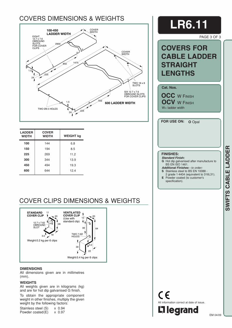
Cat. Nos.
FOR USE ON:
FINISHES:
EM 04/09
All information correct at date of issue.
SW
IFT
S C
AB
LE
LA
DD
ER
STANDARDCOVER CLIP 20
12.7 x 7.62OBROUNDSLOT
18
28
11
3.0
13
30
22
39
20
64
3.0
TWO 7.0ØHOLES
VENTILATEDCOVER CLIP(Use withstandard clip)
Weight:0.2 kg per 6 clips
Weight:0.4 kg per 6 clips
TWO Ø9.5 HOLES
24
1475
225
TWO 18 x 8SLOTS
1.5 600 LADDER WIDTH
EIGHT12.7 x 7.6OBROUNDSLOTSFOR COVERCLIPS
100-450LADDER WIDTH
225
502
850
COVERWIDTH
COVERWIDTH
2900
24
1.5
SIX 12.7 x 7.6OBROUND SLOTSFOR COVER CLIPS
COVERS DIMENSIONS & WEIGHTS
LADDERWIDTH
100
150
225
300
450
600
LR6.11PAGE 3 OF 3
W= ladder width
OCC W FINISH
OCV W FINISH
O Opal
COVERS FORCABLE LADDERSTRAIGHTLENGTHS
COVER CLIPS DIMENSIONS & WEIGHTS
COVERWIDTH WEIGHT kg
6.8
8.5
11.2
13.9
19.3
12.4
144
194
269
344
494
644
Standard Finish:G Hot dip galvanised after manufacture to
BS EN ISO 1461.Additional Finishes - to order:S Stainless steel to BS EN 10088 -
2 grade 1·4404 (equivalent to 316L31).E Powder coated (to customer's
specification).
DIMENSIONSAll dimensions given are in millimetres(mm).
WEIGHTSAll weights given are in kilograms (kg)and are for hot dip galvanised G finish.To obtain the appropriate componentweight in other finishes, multiply the givenweight by the following factors:Stainless steel (S) x 0.94Powder coated(E) x 0.97
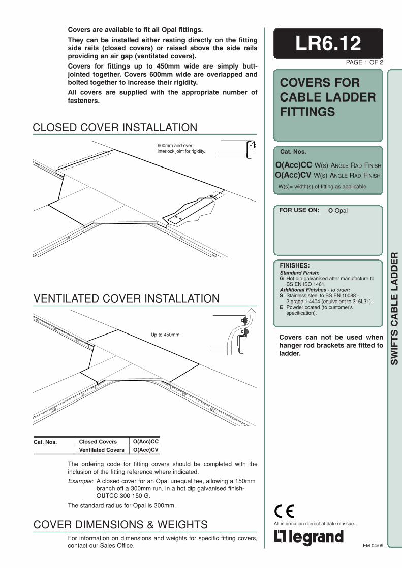
Cat. Nos.
FOR USE ON:
FINISHES:
EM 04/09
All information correct at date of issue.
SW
IFT
S C
AB
LE
LA
DD
ER
PAGE 1 OF 2
LR6.12
Up to 450mm.
Covers are available to fit all Opal fittings.
They can be installed either resting directly on the fittingside rails (closed covers) or raised above the side railsproviding an air gap (ventilated covers).
Covers for fittings up to 450mm wide are simply butt-jointed together. Covers 600mm wide are overlapped andbolted together to increase their rigidity.
All covers are supplied with the appropriate number offasteners.
VENTILATED COVER INSTALLATION
600mm and over:interlock joint for rigidity.
The ordering code for fitting covers should be completed with theinclusion of the fitting reference where indicated.
Example: A closed cover for an Opal unequal tee, allowing a 150mmbranch off a 300mm run, in a hot dip galvanised finish-OUTCC 300 150 G.
The standard radius for Opal is 300mm.
Cat. Nos. Closed Covers
Ventilated Covers
For information on dimensions and weights for specific fitting covers,contact our Sales Office.
COVER DIMENSIONS & WEIGHTS
O(ACC)CC W(S) ANGLE RAD FINISH
O(ACC)CV W(S) ANGLE RAD FINISH
W(s)= width(s) of fitting as applicable
O Opal
COVERS FORCABLE LADDERFITTINGS
CLOSED COVER INSTALLATION
O(Acc)CC
O(Acc)CV
FINISHES:Standard Finish:G Hot dip galvanised after manufacture to
BS EN ISO 1461.Additional Finishes - to order:S Stainless steel to BS EN 10088 -
2 grade 1·4404 (equivalent to 316L31).E Powder coated (to customer's
specification).
Covers can not be used whenhanger rod brackets are fitted toladder.

EM 04/09
All information correct at date of issue.
SW
IFT
S C
AB
LE
LA
DD
ER
FASTENERS (included):
ABC D
F
VENTILATEDCOVER
A
BD
C
CLOSEDCOVER
E
(one fastenerper clip)
(two fastenersper clip)
COVER CLIP POSITIONSCover clip positions for the various fitting covers are shown below.
FLAT BENDCOVER
TEECOVER
4-WAY CROSSPIECECOVER
REDUCERCOVER
RISERCOVER
Cover clips
COVER CLIPS DIMENSIONS & WEIGHTSRefer to Data Sheet LR6.11 (page 2) for cover clips dimensions and weights.
CLOSED COVERSTo fit covers as closed, fit the cover over thefitting side rails and place the cover clips inposition under the side rail top flanges. Fitand tighten the fasteners.
VENTILATED COVERSTo fit the covers as ventilated, attach theextension cover clips to the cover and placethe cover in position on the fitting with theextension clips seated on the top flange ofthe fitting side rails. Position the standardcover clips in line with the extension clips andunder the side rail top flanges. Fit fastenersthrough both clips and tighten.
JOINING COVERSWhen 600mm wide covers are fitted, thefitting cover may join to either end of astraight length cover.
If the straight cover has an overlap tongue,push 'U'-shaped retaining nuts over theholes in the tongue. Fit the fitting cover inposition overlapping the tongue. Insertfasteners through both covers and theretaining nuts and tighten the fasteners.
If the straight cover has not got an overlaptongue, fit four 'U'-shaped retaining nutsover the holes in a joint strip and position thestrip under the butt-join between covers.Insert fasteners through each cover and thetwo aligning holes in the joint strip andtighten the fasteners.
NOTE: It may be necessary to drill holesin the straight cover if it has beencut to length.
LR6.12PAGE 2 OF 2
SIDE RAIL
COVER
CLIP
SIDE RAIL
70 mmCOVER
STANDARDCLIP
VENTILATEDCOVERCLIP
ASSEMBLY
A M6x12 roofing boltB Cover clip (standard)C M6 square nutD Side railE CoverF Cover clip (extension)
J K L M
JOINT STRIP(four fasteners per joint)
GH
GH
JKL
G M6 form A washerH Spring washerJ CoverK 'U'-shape retaining nutL M6x16 setscrewM Joint strip
Finish: For covers with G finish, fasteners aregalvanised or zinc plated, except forretaining nut which is 'Dacromet'coated. For covers with S finish,fasteners are stainless steel except forretaining nut which is 'Xylan' coated. Forcovers with E finish, the fasteners areGrade 8.8 hot dip galvanised. Analternative material for fasteners maybe required depending on theinstallation environment - contactour Sales Office for guidance.
'U'-SHAPEDRETAININGNUT
FIRST COVER
SECOND COVER
45
350
250FOUR 12 x 7OBROUND SLOTS
DRILLEDHOLES
JOINTSTRIP
EXISTINGSLOTS
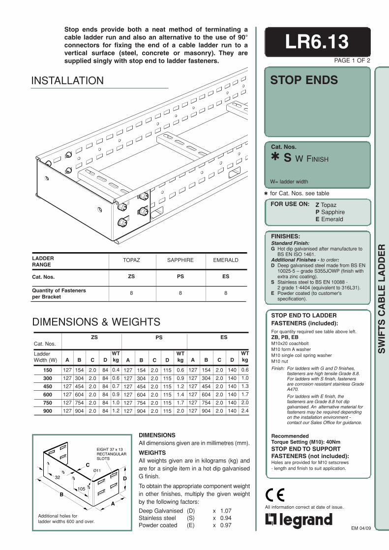
Cat. Nos.
FOR USE ON:
FINISHES:
EM 04/09
All information correct at date of issue.
SW
IFT
S C
AB
LE
LA
DD
ER
LADDERRANGE
Cat. Nos.
Quantity of Fastenersper Bracket
Additional holes forladder widths 600 and over.
C
A
D
B
Ø11
32
105
EIGHT 37 x 13RECTANGULARSLOTS
B
154
304
454
604
754
904
Cat. Nos.
LadderWidth (W)
150
300
450
600
750
900
C
2.0
2.0
2.0
2.0
2.0
2.0
D
84
84
84
84
84
84
ZS PS ES
A
127
127
127
127
127
127
D
115
115
115
115
115
115
WTkg
0.6
0.9
1.2
1.4
1.7
2.0
D
140
140
140
140
140
140
WTkg
0.6
1.0
1.3
1.7
2.0
2.4
WTkg
0.4
0.6
0.7
0.9
1.0
1.2
A
127
127
127
127
127
127
B
154
304
454
604
754
904
C
2.0
2.0
2.0
2.0
2.0
2.0
A
127
127
127
127
127
127
B
154
304
454
604
754
904
C
2.0
2.0
2.0
2.0
2.0
2.0
DIMENSIONS & WEIGHTS
PAGE 1 OF 2
LR6.13
for Cat. Nos. see table
S W FINISH
W= ladder width
STOP ENDS
Stop ends provide both a neat method of terminating acable ladder run and also an alternative to the use of 90°connectors for fixing the end of a cable ladder run to avertical surface (steel, concrete or masonry). They aresupplied singly with stop end to ladder fasteners.
INSTALLATION
EMERALD
ES
8
SAPPHIRE
PS
8
TOPAZ
ZS
8
FOR USE ON: Z TopazP SapphireE Emerald
FINISHES:Standard Finish:G Hot dip galvanised after manufacture to
BS EN ISO 1461.Additional Finishes - to order:D Deep galvanised steel made from BS EN
10025-5 – grade S355JOWP (finish withextra zinc coating).
S Stainless steel to BS EN 10088 -2 grade 1·4404 (equivalent to 316L31).
E Powder coated (to customer'sspecification).
STOP END TO LADDERFASTENERS (included):For quantity required see table above left.ZB, PB, EBM10x20 coachboltM10 form A washerM10 single coil spring washerM10 nut
Finish: For ladders with G and D finishes,fasteners are high tensile Grade 8.8.For ladders with S finish, fastenersare corrosion resistant stainless GradeA470.
For ladders with E finish, thefasteners are Grade 8.8 hot dipgalvanised. An alternative material forfasteners may be required dependingon the installation environment -contact our Sales Office for guidance.
RecommendedTorque Setting (M10): 40NmSTOP END TO SUPPORTFASTENERS (not included):Holes are provided for M10 setscrews- length and finish to suit application.
DIMENSIONSAll dimensions given are in millimetres (mm).
WEIGHTSAll weights given are in kilograms (kg) andare for a single item in a hot dip galvanisedG finish.
To obtain the appropriate component weightin other finishes, multiply the given weightby the following factors:
Deep Galvanised (D) x 1.07Stainless steel (S) x 0.94Powder coated (E) x 0.97

Cat. Nos.
FOR USE ON:
FINISHES:
EM 04/09
All information correct at date of issue.
SW
IFT
S C
AB
LE
LA
DD
ER
Additional centre hole forladder width 600 only.
LR6.13PAGE 2 OF 2
Stop ends provide both a neat method of terminating a cableladder run and also an alternative to the use of 90° connectorsfor fixing the end of a cable ladder run to a vertical surface(steel, concrete or masonry). They are supplied singly withstop end to ladder fasteners.
WEIGHTkg
0.2
0.2
0.3
0.4
0.5
0.6
LadderWidth (W)
100
150
225
300
450
600
A
100
100
100
100
100
100
C
2.0
2.0
2.0
2.0
2.0
2.0
D
45
45
45
45
45
45
DIMENSIONSAll dimensions given are in millimetres (mm).
WEIGHTSAll weights given are in kilograms (kg) andare for a single item in a hot dip galvanised Gfinish.
To obtain the appropriate component weightin other finishes, multiply the given weight bythe following factors:
Stainless steel (S) x 0.94Powder coated (E) x 0.97
B
97
147
223
297
447
597
W= ladder width
OS W FINISH
C
A
D
B
28Ø7.5
EIGHT 15 x 7OBROUNDSLOTS
Opal stop ends must be fitted to the inside of the ladder side rails.
STOP ENDS INSTALLATION
DIMENSIONS & WEIGHTS
FOR USE ON:
FINISHES:Standard Finish:G Hot dip galvanised after manufacture to
BS EN ISO 1461.Additional Finishes - to order:S Stainless steel to BS EN 10088 -
2 grade 1·4404 (equivalent to 316L31).E Powder coated (to customer's
specification).
O Opal
STOP END TO LADDERFASTENERS (included):Four fasteners per bracket.M6x16 setscrewM6 washerM6 shakeproof washerM6 nutFinish: For ladders with G finish, fasteners are
high tensile Grade 8.8. For ladders withS finish, fasteners are corrosionresistant stainless Grade A470.For ladders with E finish, the fastenersare Grade 8.8 hot dip galvanised. Analternative material for fasteners maybe required depending on the installationenvironment - contact our Sales Officefor guidance.
STOP END TO SUPPORTFASTENERS (not included):Holes are provided for M6 setscrews- length and finish to suit application.

Cat. Nos.
FOR USE ON:
FINISHES:
EM 04/09
All information correct at date of issue.
SW
IFT
S C
AB
LE
LA
DD
ERLADDER TO LADDER CONNECTION TRAY TO LADDER CONNECTION
LR6.14PAGE 1 OF 1
23
260
85
3
EIGHT 20 x 7OBROUNDSLOTS
EIGHT 37 x 13RECTANGULARSLOTS
Rail to rail dropout brackets are used:
a. to attach a vertical cable ladder run beneath a horizontalmain ladder run of the same width.
b. to attach a vertical cable tray run beneath one side railof a horizontal main ladder run.
A bracket suitable for Opal is available, ReferenceOM/FINISH, contact our Sales Office for details.
Rail to rail dropout brackets are supplied in pairs withfasteners.
M FINISH
Important
Unless the connecting vertical ladder or tray is properlysupported at a lower position it must be considered as a pointload imposed on the main ladder run, any implications of whichmust be properly considered.
Weight of one pair of brackets: 1.0kg.
RAIL TO RAILDROPOUTBRACKETS
DIMENSIONS & WEIGHTS
INSTALLATIONS
FOR USE ON: Z TopazP SapphireE Emerald
FINISHES:Standard Finish:G Hot dip galvanised after manufacture to
BS EN ISO 1461.Additional Finishes - to order:D Deep galvanised steel made from BS EN
10025-5 – grade S355JOWP (finish withextra zinc coating).
S Stainless steel to BS EN 10088 -2 grade 1·4404 (equivalent to 316L31).
E Powder coated (to customer'sspecification).
BRACKET TO LADDERFASTENERS (included):Five fasteners per bracket.
M10 x 20 coachboltM10 form A washerM10 single coil spring washerM10 nut
Finish: For ladders with G and D finishes,fasteners are high tensile Grade 8.8.For ladders with S finish, fastenersare corrosion resistant stainless GradeA470.
For ladders with E finish, thefasteners are Grade 8.8 hot dipgalvanised. An alternative material forfasteners may be required dependingon the installation environment -contact our Sales Office for guidance.
RecommendedTorque Setting (M10): 40Nm
BRACKET TO TRAY FASTENERS(not included):M6 nuts and bolts (roofing or pan head).
DIMENSIONSAll dimensions given are in millimetres (mm).
WEIGHTSThe weight given is in kilograms (kg) and isfor one pair of brackets in a hot dipgalvanised G finish.
To obtain the appropriate component weightin other finishes, multiply the given weight bythe following factors:
Deep Galvanised (D) x 1.07Stainless steel (S) x 0.94Powder coated (E) x 0.97

Cat. Nos.
FOR USE ON:
FINISHES:
EM 04/09
All information correct at date of issue.
SW
IFT
S C
AB
LE
LA
DD
ER
A
2.0
20
UPTO 450 WIDETWO 25 x 7OBROUND SLOTS
600 WIDE AND ABOVETHREE 25 x 7OBROUND SLOTS
90o
LR6.15Dropout plates are designed to provide local support to cablesas they exit a cable ladder run by passing between the rungs.
Dropout plates are supplied singly with fasteners.
INSTALLATION
DIMENSIONS & WEIGHTS
A
80
130
205
280
430
580
730
880
100
150
225
300
450
600
750
900
Ladder Width(W)
WEIGHTkg
0.5
0.8
1.3
1.7
2.7
3.6
4.5
5.5
PAGE 1 OF 1
DO W FINISH
W = ladder width
DROPOUTPLATES
DIMENSIONSAll dimensions given are in millimetres (mm).
WEIGHTSAll weights given are in kilograms (kg) andare for a single item in a hot dip galvanisedG finish.
To obtain the appropriate component weightin other finishes, multiply the given weightby the following factors:
Deep Galvanised (D) x 1.07Stainless steel (S) x 0.94Powder coated (E) x 0.97
O/- OpalFOR USE ON: O OpalZ TopazP SapphireE Emerald
FASTENERS (included):Two fasteners per plate up to 450mm wide.Three fasteners per plate 600mm wide andabove.
G & D finishesM6 x12 roofing boltM6 roofing washers (2 off)M6 nut
S finishM6 x12 pan head screwM6 form A washerM6 square washerM6 nut
Finish: For ladders with G and D finishes,fasteners are high tensile Grade 8.8.For ladders with S finish, fastenersare corrosion resistant stainless GradeA470.
For ladders with E finish, thefasteners are Grade 8.8 hot dipgalvanised. An alternative material forfasteners may be required dependingon the installation environment -contact our Sales Office for guidance.
FINISHES:Standard Finish:G Hot dip galvanised after manufacture to
BS EN ISO 1461.Additional Finishes - to order:D Deep galvanised steel made from BS EN
10025-5 – grade S355JOWP (finish withextra zinc coating).
S Stainless steel to BS EN 10088 -2 grade 1·4404 (equivalent to 316L31).
E Powder coated (to customer'sspecification).
Note: D not available for Opal

Cat. Nos.
FOR USE ON:
FINISHES:
EM 04/09
All information correct at date of issue.
SW
IFT
S C
AB
LE
LA
DD
ER
100mmMinimum
Weight: 0.3kg
INSTALLATIONS
Cable support brackets are designed for use with all cableladder ranges when the ladder is installed with the rungsvertical.
Several brackets can be fitted to each rung at a minimumspacing of 100mm. The maximum recommended cableloading is 30kg per bracket.
Cable support brackets are supplied singly with fastenersbut without cable ties.
LR6.16PAGE 1 OF 1
CABLESUPPORTBRACKET
CSB FINISH
O/- OpalFOR USE ON: O OpalZ TopazP SapphireE Emerald
Ø7.5 MOUNTING HOLE
3.0
56.0
76.5
TWO 5 x 16OBROUND SLOTS
71.5 x 7.5OBROUND SLOT
93.0
DIMENSIONS & WEIGHTS
WEIGHTSThe weight given is in kilograms (kg)and is for a single item in a hot dipgalvanised G finish.
To obtain the appropriate componentweight in other finishes, multiply thegiven weight by the following factors:
Deep Galvanised (D) x 1.07Stainless steel (S) x 0.94Powder coated (E) x 0.97
DIMENSIONSAll dimensions given are in millimetres (mm).
FASTENERS (included):One fastener per bracket.
G & D finishesM6 x12 roofing boltM6 roofing washers (2 off)M6 nut
S finishM6 x12 pan head screwM6 form A washerM6 square washerM6 nut
Finish: For ladders with G and D finishes,fasteners are high tensile Grade 8.8.For ladders with S finish, fastenersare corrosion resistant stainless GradeA470.
For ladders with E finish, thefasteners are Grade 8.8 hot dipgalvanised. An alternative material forfasteners may be required dependingon the installation environment -contact our Sales Office for guidance.
FINISHES:Standard Finish:G Hot dip galvanised after manufacture to
BS EN ISO 1461.Additional Finishes - to order:D Deep galvanised steel made from BS EN
10025-5 – grade S355JOWP (finish withextra zinc coating).
S Stainless steel to BS EN 10088 -2 grade 1·4404 (equivalent to 316L31).
E Powder coated (to customer'sspecification).
Note: D not available for Opal
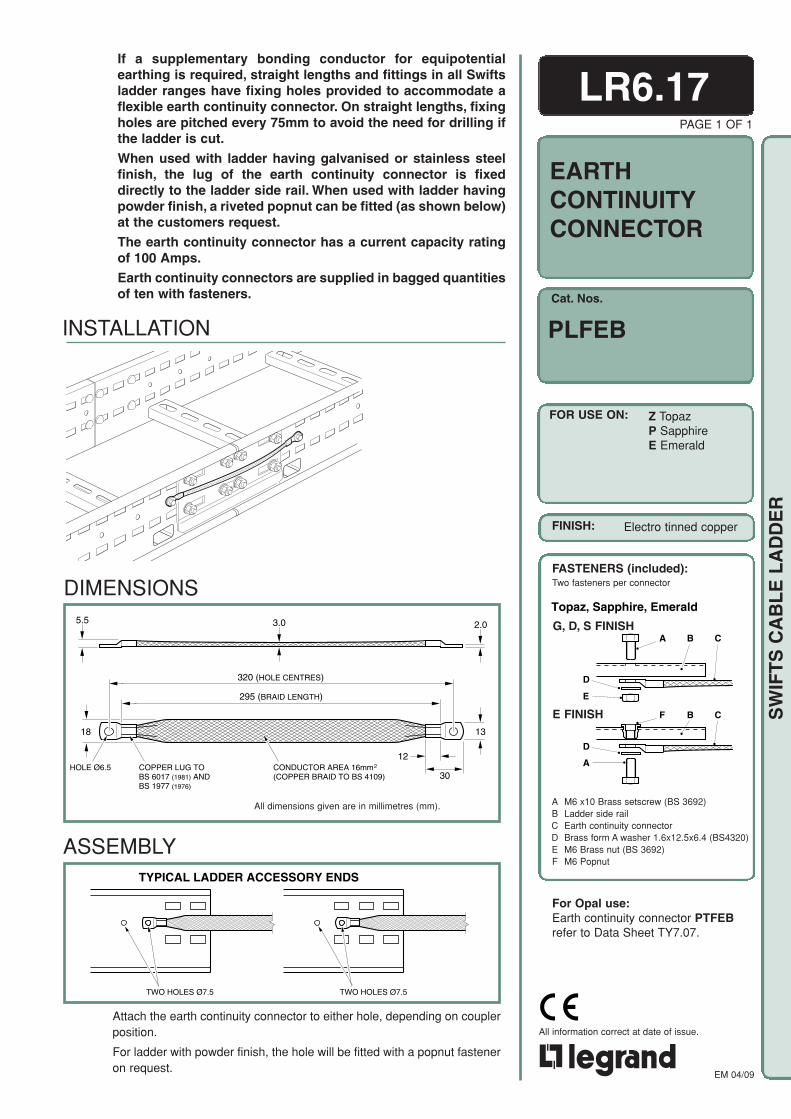
Cat. Nos.
FOR USE ON:
FINISHES:
EM 04/09
All information correct at date of issue.
SW
IFT
S C
AB
LE
LA
DD
ER
LR6.17If a supplementary bonding conductor for equipotentialearthing is required, straight lengths and fittings in all Swiftsladder ranges have fixing holes provided to accommodate aflexible earth continuity connector. On straight lengths, fixingholes are pitched every 75mm to avoid the need for drilling ifthe ladder is cut.
When used with ladder having galvanised or stainless steelfinish, the lug of the earth continuity connector is fixeddirectly to the ladder side rail. When used with ladder havingpowder finish, a riveted popnut can be fitted (as shown below)at the customers request.
The earth continuity connector has a current capacity ratingof 100 Amps.
Earth continuity connectors are supplied in bagged quantitiesof ten with fasteners.
PAGE 1 OF 1
EARTHCONTINUITYCONNECTOR
PLFEB
Z TopazP SapphireE Emerald
TYPICAL LADDER ACCESSORY ENDS
TWO HOLES Ø7.5TWO HOLES Ø7.5
ASSEMBLY
DIMENSIONS
All dimensions given are in millimetres (mm).
Attach the earth continuity connector to either hole, depending on couplerposition.
For ladder with powder finish, the hole will be fitted with a popnut fasteneron request.
FINISH: Electro tinned copper
FASTENERS (included):Two fasteners per connector
Topaz, Sapphire, EmeraldSwiftspan G, Swiftspan H-/G, -/DG,-/SS FINISH
A B C
D
E
-/E FINISH F B C
D
A
A M6 x10 Brass setscrew (BS 3692)B Ladder side railC Earth continuity connectorD Brass form A washer 1.6x12.5x6.4 (BS4320)E M6 Brass nut (BS 3692)F M6 Popnut
For Opal use:Earth continuity connector PTFEBrefer to Data Sheet TY7.07.
INSTALLATION
COPPER LUG TOBS 6017 (1981) ANDBS 1977 (1976)
1318
30
12
295 (BRAID LENGTH)
320 (HOLE CENTRES)
HOLE Ø6.5 CONDUCTOR AREA 16mm(COPPER BRAID TO BS 4109)
2
3.05.5 2.0 G, D, S FINISH
E FINISH
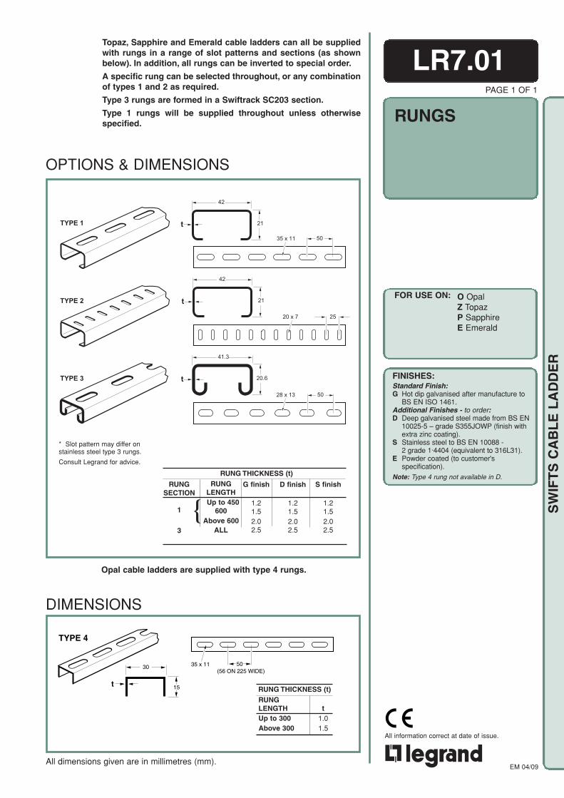
EM 04/09
All information correct at date of issue.
SW
IFT
S C
AB
LE
LA
DD
ER
LR7.01Topaz, Sapphire and Emerald cable ladders can all be suppliedwith rungs in a range of slot patterns and sections (as shownbelow). In addition, all rungs can be inverted to special order.
A specific rung can be selected throughout, or any combinationof types 1 and 2 as required.
Type 3 rungs are formed in a Swiftrack SC203 section.
Type 1 rungs will be supplied throughout unless otherwisespecified.
PAGE 1 OF 1
RUNGS
FOR USE ON:
OPTIONS & DIMENSIONS
All dimensions given are in millimetres (mm).
O OpalZ TopazP SapphireE Emerald
t
42
TYPE 2
TYPE 1 21
t
42
21
TYPE 3
28 x 13
35 x 11
20 x 7
50
50
25
t
41.3
20.6
RUNGSECTION
1
3
{RUNG
LENGTHUp to 450
600Above 600
ALL
G finish
1.21.52.02.5
D finish
1.21.52.02.5
S finish
1.21.52.02.5
RUNG THICKNESS (t)
* Slot pattern may differ onstainless steel type 3 rungs.
Consult Legrand for advice.
TYPE 4
t
30
15
35 x 11 50(56 ON 225 WIDE)
RUNGLENGTHUp to 300Above 300
RUNG THICKNESS (t)
t1.01.5
DIMENSIONS
FINISHES:Standard Finish:G Hot dip galvanised after manufacture to
BS EN ISO 1461.Additional Finishes - to order:D Deep galvanised steel made from BS EN
10025-5 – grade S355JOWP (finish withextra zinc coating).
S Stainless steel to BS EN 10088 -2 grade 1·4404 (equivalent to 316L31).
E Powder coated (to customer'sspecification).
Note: Type 4 rung not available in D.
Opal cable ladders are supplied with type 4 rungs.

EM 04/09
All information correct at date of issue.
SW
IFT
S C
AB
LE
LA
DD
ER
A
C
B
D
E
F
LR7.02PAGE 1 OF 1
The effect of lateral loads on spans over 5m or 6m can bemuch reduced by adding diagonal bracing.
Bracing is achieved by fitting a ladder type 1 rung section,cut to length from 3m length supplied, diagonally across theunderside of the ladder as shown in the illustration below.
Diagonal bracing can be fitted to Sapphire or Emerald cableladder; Opal and Topaz are not suitable for these long spans.
FOR USE ON:
ASSEMBLY DETAILS(Fasteners not included):
DIAGONALBRACING
A M10 Swiftrack channel nut (Ref. PN 100)B Ladder rungC 40x40x6 square washer, SB506/10D Diagonal brace (type 1 rung 1.5 thick)E M10 form A washer FM10x25 Grade 8.8 setscrew
Finish: For ladders with S finish, fastenersare corrosion resistant Stainless GradeA470.
INSTALLATIONCouplers are best located directly over the point of support toprovide additional local reinforcement of the ladder side rails.
Details on long span installations are given in Section 2 of theEngineering Manual, refer to Cable Tray and Cable Ladder systems,Installation of Cable Ladder Over Long Spans.
DIAGONAL BRACE (3m LONG)CUT TO LENGTH AS REQUIRED
LADDER RUNG
6m SPAN
1.8mTYPICAL
DIAGONAL BRACE BOLTEDTO UNDERSIDE OF ALTERNATELADDER RUNGS
SUPPORT SUPPORT
COUPLER
Cat. Nos.
LR FINISH
Supplied in 3m length
For details of rung section refer to Data Sheet LR7.01.
P SapphireE Emerald
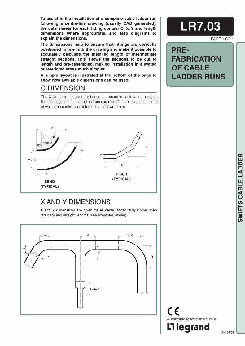
EM 04/09
All information correct at date of issue.
SW
IFT
S C
AB
LE
LA
DD
ER
C DIMENSIONThe C dimension is given for bends and risers in cable ladder ranges.It is the length of the centre-line from each "end" of the fitting to the pointat which the centre-lines intersect, as shown below.
CX
Y
BEND(TYPICAL)
RISER(TYPICAL)
X and Y dimensions are given for all cable ladder fittings other thanreducers and straight lengths (see examples above).
Y
C, XXC
Y
X
Y
LENGTH
LR7.03
PRE-FABRICATIONOF CABLELADDER RUNS
To assist in the installation of a complete cable ladder runfollowing a centre-line drawing (usually CAD generated),the data sheets for each fitting contain C, X, Y and lengthdimensions where appropriate, and also diagrams toexplain the dimensions.
The dimensions help to ensure that fittings are correctlypositioned in line with the drawing and make it possible toaccurately calculate the installed length of intermediatestraight sections. This allows the sections to be cut tolength and pre-assembled, making installation in elevatedor restricted areas much simpler.
A simple layout is illustrated at the bottom of the page toshow how available dimensions can be used.
PAGE 1 OF 1
X AND Y DIMENSIONS
X
80
80RADIUS
C
WIDTH
Y

EM 04/09
All information correct at date of issue.
SW
IFT
S C
AB
LE
LA
DD
ER
WIDTH
LR7.04
IDENTIFICATIONANDRECOGNITION OFCABLE LADDERFITTINGS
Under site conditions it is often difficult to distinguish betweendifferent fittings, particularly bends and risers of varyingangles and radii. To assist identification, key dimensionvalues are given on each fitting data sheet to provide asimple means of differentiating between similar fittings.
The available widths, or combinations of widths, for all fittings arealways listed, and are a necessity for positive identification.
i DIMENSIONThis dimension identifies those fittings in the cable ladder ranges whichhave curved sections or change the direction of the run through varyingangles. It is the measurement across the inner curve of the fitting, asshown below, and is a constant for each available radius option.
i
i
i
EQUAL TEE,UNEQUAL TEE,CROSSPIECE
RISER
BEND
X, Y AND C DIMENSIONSFor cable ladder fittings without an i dimension, the X, Y and Cdimensions (where applicable) can be used. These are listed in eachfitting data sheet and explained in Data Sheets LR7.03.
PAGE 1 OF 1