low voltage system (lv) - amultender.amuldairy.com/download/tender37_1.pdflow voltage system (lv)...
TRANSCRIPT

TENDER DOCUMENTS
Low Voltage System (LV)
FOR
800 MTPD exp. upto 1600 MTPD CATTLE FEED PLANT ON 20
HRS OPERATION BASIS
AT: Kapdivav, P.O. Chikhload, Taluka – Kapadwanj, Dist. – Kheda, Gujarat
BID REFERENCE NO: AMUL/CFF-6/KAPDIVAV/2014
KAIRA DISTRICT CO-OPERATIVE MILK PRODUCERS’ UNION LIMITED
AMUL DAIRY, ANAND, GUJARAT-388 OO1

KKaaiirraa DDiissttrriicctt CCoo--ooppeerraattiivvee MMiillkk PPrroodduucceerrss’’ UUnniioonn LLiimmiitteedd..
Amul Dairy, Anand- 388 001, Gujarat (India)
Phone: +91-2692-225473, Fax: +91-2692-225475
Invitation For Bid (IFB)
Bid
Reference AMUL/CFF-6/KAPDIVAV/2014
Name of
Project
CATTLE FEED
FACTORY, KAPADWANJ
SN Description Estimated Cost
(`.)
EMD
(`.)
1 Low Voltage System. 1.59 Crores 1.59 Lacs
Duration (months) 3 Months
Bidding Document Sale.
Start 20.02.2014, Thursday.
Stop 07.03.2014, Friday.
Last Date & Time of Bid.
Submission 07.03.2014 at 15.00 Hrs., Friday.
Tender Opening 08.03.2014 at 15.00 Hrs., Saturday.
Date of Pre Bid Meeting. 24.02.2014 at 11.00 Hrs, Monday
Place of Pre-Bid Meeting
Office of:
General Manager (Projects & Engineering)
Amul Dairy Road, Anand 388 001.
Phone: (02692) 225 473
Place of Tender Opening.
Office of:
General Manager (Projects & Engineering)
Amul Dairy Road, Anand 388 001.
Phone: (02692) 225 473
Material Specifications for CATTLE FEED PLANT AT KAPADWANJ MS
- 1 -
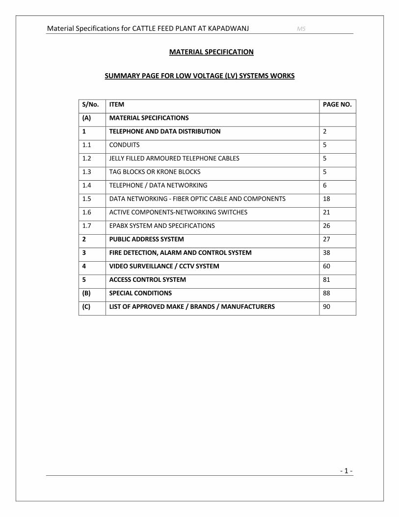
MATERIAL SPECIFICATION
SUMMARY PAGE FOR LOW VOLTAGE (LV) SYSTEMS WORKS
S/No. S/No. ITEM PAGE NO.
(A) MATERIAL SPECIFICATIONS
1 TELEPHONE AND DATA DISTRIBUTION 2
1.1 CONDUITS 5
1.2 JELLY FILLED ARMOURED TELEPHONE CABLES 5
1.3 TAG BLOCKS OR KRONE BLOCKS 5
1.4 TELEPHONE / DATA NETWORKING 6
1.5 DATA NETWORKING - FIBER OPTIC CABLE AND COMPONENTS 18
1.6 ACTIVE COMPONENTS-NETWORKING SWITCHES 21
1.7 EPABX SYSTEM AND SPECIFICATIONS 26
2 PUBLIC ADDRESS SYSTEM 27
3 FIRE DETECTION, ALARM AND CONTROL SYSTEM 38
4 VIDEO SURVEILLANCE / CCTV SYSTEM 60
5 ACCESS CONTROL SYSTEM 81
(B) SPECIAL CONDITIONS 88
(C) LIST OF APPROVED MAKE / BRANDS / MANUFACTURERS 90
Material Specifications for CATTLE FEED PLANT AT KAPADWANJ MS
- 2 -
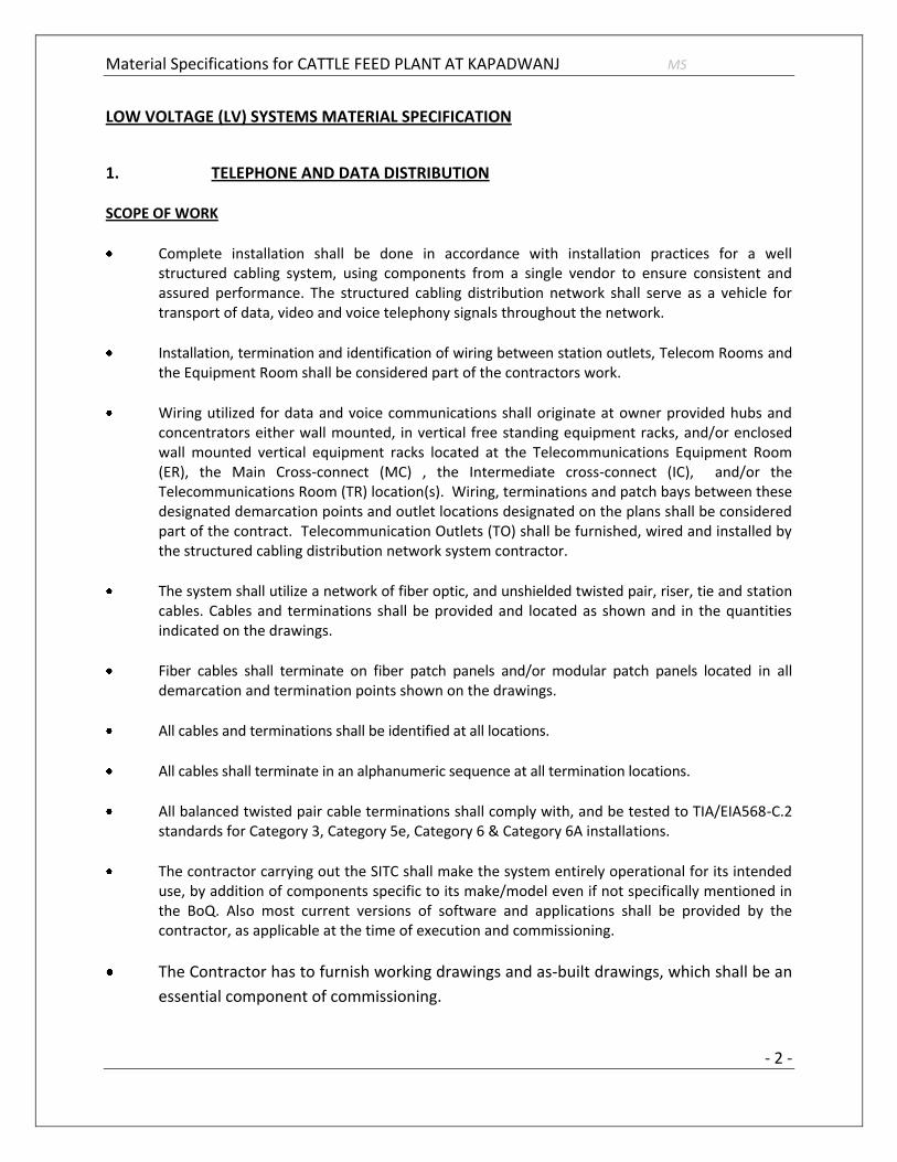
LOW VOLTAGE (LV) SYSTEMS MATERIAL SPECIFICATION
1. TELEPHONE AND DATA DISTRIBUTION SCOPE OF WORK
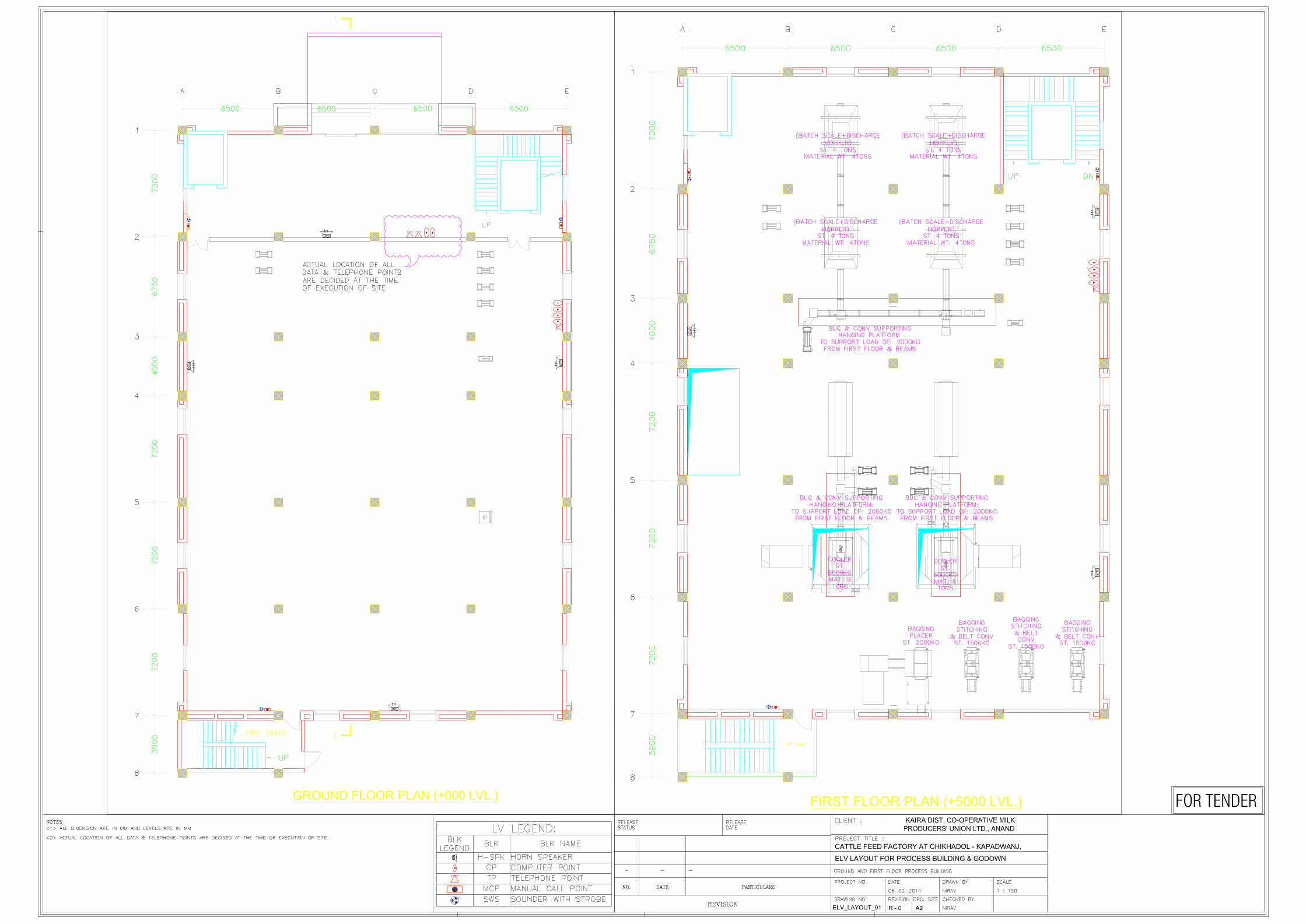
Complete installation shall be done in accordance with installation practices for a well structured cabling system, using components from a single vendor to ensure consistent and assured performance. The structured cabling distribution network shall serve as a vehicle for transport of data, video and voice telephony signals throughout the network.
Installation, termination and identification of wiring between station outlets, Telecom Rooms and the Equipment Room shall be considered part of the contractors work.
Wiring utilized for data and voice communications shall originate at owner provided hubs and concentrators either wall mounted, in vertical free standing equipment racks, and/or enclosed wall mounted vertical equipment racks located at the Telecommunications Equipment Room (ER), the Main Cross-connect (MC) , the Intermediate cross-connect (IC), and/or the Telecommunications Room (TR) location(s). Wiring, terminations and patch bays between these designated demarcation points and outlet locations designated on the plans shall be considered part of the contract. Telecommunication Outlets (TO) shall be furnished, wired and installed by the structured cabling distribution network system contractor.
The system shall utilize a network of fiber optic, and unshielded twisted pair, riser, tie and station cables. Cables and terminations shall be provided and located as shown and in the quantities indicated on the drawings.
Fiber cables shall terminate on fiber patch panels and/or modular patch panels located in all demarcation and termination points shown on the drawings.
All cables and terminations shall be identified at all locations.
All cables shall terminate in an alphanumeric sequence at all termination locations.
All balanced twisted pair cable terminations shall comply with, and be tested to TIA/EIA568-C.2 standards for Category 3, Category 5e, Category 6 & Category 6A installations.
The contractor carrying out the SITC shall make the system entirely operational for its intended use, by addition of components specific to its make/model even if not specifically mentioned in the BoQ. Also most current versions of software and applications shall be provided by the contractor, as applicable at the time of execution and commissioning.
The Contractor has to furnish working drawings and as-built drawings, which shall be an
essential component of commissioning.

Material Specifications for CATTLE FEED PLANT AT KAPADWANJ MS
- 3 -
Supported Applications, but not limited to:
Ethernet Applications
IEEE 802.3af Data Terminal Equipment (DTE) Power via Media Dependent Interface (MDI)
Fiber Channel Applications
IEEE 802.11a/b/g Wireless LAN Applications
Digital Subscriber Loop (DSL) Applications
Voice, Video and ISDN Applications
Building Automation Systems (BAS) Applications
References & Standards, but not limited to:
TIA / EIA
International Electro technical Commission (IEC)
European Committee for Electro technical Standardization (CENELEC)
National Fire Protection Association (NFPA)
It shall be the responsibility of the installer and OEM manufacturer to ensure that:
The Passive Components of structured cabling distribution network will be free from manufacturing defects in material and workmanship under normal and proper use;
All Passive Components in the structured cabling distribution network meet or exceed the relevant component specification of the TIA 568-B series and ISO/IEC 11801: 2002 standards;
The structured cabling distribution network compliant channels will meet or exceed the Guaranteed Channel Performance as per relevant standards in the structured cabling distribution network Performance Specifications in effect at the time of installation.
The Application Assurance covers the structured cabling distribution network compliant channels to support operations of the application(s) that the system was designed to support.
The site will be duly certified by OEM for a period of Twenty years from the date of issuance of the registration certificate or installation, whichever is earlier.

Material Specifications for CATTLE FEED PLANT AT KAPADWANJ MS
- 4 -
The Items, and the Specifications for the same in this section, applies to the following:
Jelly Filled Armoured Telephone Cable
Category 6 Data Networking UTP Cable and associated components such as CAT6 patch panels – 16/24/48 ports, IOs/RJ45 jacks, CAT6 patch cords, Face plates & SMBs
Multimode Outdoor/Indoor Optic Fiber Cable and accessories such as – Light Guide Interface Unit (LIU), wall mount and rack mount, pigtail, splices, couplers, patch cords, splicing kit and splice trays
Networking Racks – for termination of networking cables
Equipment Racks – for servers and hardware
Wire-Less Access Point & Fiber Optic Media Convertor
Networking Switches – Simple Manageable, Layer 2 & Layer 3 inclusive of their options such as uplinks, transceivers for fiber transmission
Installation:
The installation of conduits shall generally be as specified under section ̀ CONDUIT WIRING'.
All cables shall be on cable racks and neatly stitched together.
The connection at the tag blocks shall be silver soldered of IDC type so as to achieve minimum contact resistance gas tight connection.
The final branch connections with single pair cables in conduits and the maximum number of cables in each conduit shall be as follows :
Conduit Diameter Inch/mm. Max. No. of cables
1" 25 4 Nos. Of CAT6 cables
1½" 40 6 Nos. Of CAT6 cables
Mode of measurement:
The main telephone/data cables shall include supply and laying of multi pair cables on ceiling/wall/on cable trays/racks including all supports and shall be measured and paid on running length basis. Cable trays/racks shall be paid for separately.
The multi pair tag blocks shall consist of two telephone connector’s strips, jumpered interconnections silver IDC terminated soldered enclosure etc. and shall be measured and paid as one unit.

Material Specifications for CATTLE FEED PLANT AT KAPADWANJ MS
- 5 -
The conduit wiring for telephone/data shall include single pair 0.6 diameter cable in heavy duty rigid, PVC conduits and shall include junction boxes, pull boxes, 2 pair 2 A connector in GI box, Perspex cover etc. and shall from one point.
1.1. CONDUITS
Conduits shall be as given below : The conduit shall generally be as specified under section `Telephone and Data Distribution.
1.2. JELLY FILLED ARMOURED TELEPHONE CABLES – 10 PAIRS
All multi core cables and wires shall be of tinned copper conductor of not less than 0.5 mm diameter and shall be colour coded twisted pairs with rip cord.
The conductor resistance shall be less than 150 ohms per KM and the insulation resistance between the conductors shall be not less than 50 mega ohms and the nominal capacitance measuring about 0.1 micro farad per kilometer.
Cables which are laid under ground or locations subject to dampness and flooding shall be filled with polyethylene compound and shall have sufficient protection against moisture and water ingress.
All armouring shall be of galvanized steel wires and protected against corrosion by an outer sheath of PVC in the case of indoor cables and polyethylene in the case of outdoor cables. Outer sheathing must be fire retarding and anti-termite.
The Jelly Filled armoured cable (JFA) shall be of 10 pairs’ capacity as required and suitable for direct burial application.
1.3. TAG BLOCKS OR KRONE BLOCKS (10/50/100)
The telephone tag blocks shall be suitable for the multi core telephone cables and shall have two terminal blocks, cross connect type. All incoming and outgoing cables shall be terminated on separate terminal blocks and termination shall be of insulation displacement type (IDC) to provide silver soldered gas tight connection. The cross connecting jumpers shall be insulated wires of same diameter and terminated using impact tool for gas tight connection. Screw connected..
The tag blocks shall be mounted inside fabricated sheet steel boxes with removable hinged over’s and shall be fully accessible. The enclosure shall be painted with 2 coats of red oxide and stove enamelled.

Material Specifications for CATTLE FEED PLANT AT KAPADWANJ MS
- 6 -
1.4. TELEPHONE/DATA NETWORKING 1.4.1. CATEGORY 6 UTP CABLE
Cable should meet or exceed the TIA Category 6 / ISO Class E attenuation specification, NEXT requirements in ISO/IEC 11801, CENELEC EN50173 and TIA/EIA 568C.2.
CAT 6 UTP balanced twisted pair cable shall conform to the Category 6 component specifications and the installed channels shall comply with the ANSI/EIA/TIA 568C.2 Category 6 and ISO/IEC 11801 Class E Channel Performance Specification
All balanced twisted pair cable and apparatus shall conform to the Category 6 component specifications an the installed channels shall comply with the Category 6/Class E Channel Performance Specification up to the maximum 100 meters (328 feet) length, including up to 6 connection points.
The high performance Category 6 UTP cable shall be of the traditional round design with mylar bisector tape
There should not be any limitation for minimum length of Cat 6 Channel (should not have high resonance problem in shorter channels.
The Category 6, 4 pair UTP channel shall support emerging high-bandwidth applications, including 1 Gbps Ethernet, potentially 1.2 Gbps ATM and 2.4 Gbps ATM, IEEE 1394B S400,Multi-Tasked Split Screen Computing, Virtual Holographic Video Conferencing, Instant Access Telemedicine, 3D CAD/CAM Engineering, Internet-Intranet Communications/Commerce, as well as all 77 channels (550 MHz) of analog broad band video
Category 6 cable shall perform on 400 % margin and at least 6 db NEXT
The Category 6 cable and components shall be electrically backward compatible with existing Category 3, 5, and 5e
Should be UL verified as Category 6 / ETL listed as Category 6, i.e., The 4 pair UTP cable shall be
UL and c (UL ) Listed Type CMP (plenum) or CM (non-plenum)
Should have thin bisector tape for additional performance benefits
Performance guaranteed to meet or exceed Category 6/Class E Channel Specifications to 550 MHz
Performance guaranteed up to 6 connections in any length channel configuration up to 100 meters
CAT 6 UTP indoor cable shall consist of 23 AWG polyethylene, insulated conductors, twisted into four pairs and shall be of the traditional round design with bisector tape and jacketed with a non-plenum polyethylene jacket.

Material Specifications for CATTLE FEED PLANT AT KAPADWANJ MS
- 7 -
Category 6/Class E NEXT, PSNEXT, FEXT, ELFEXT, PSELFEXT and return loss extrapolated to 250 MHz
Cable should be capable of delivering potentially in excess of 1.2 Gbps to the workstation in accordance with application standards.
The cable shall support Voice, Analog Baseband Video/Audio, Fax, Modem,Switched-56, T- 1, ISDN,RS-232, RS422, RS-485, 10BASE – T Ethernet, Token Ring, 100Mbps TP-PMD, 100BASE-T Ethernet, Ethernet IEEE 802.3 1000BASE-T, TIA-854-A 1000BASE-TX, 155 Mbps ATM, AES/EBU Digital Audio, 270 Mbps Digital Video, 622 Mbps 64-CAP ATM and emerging high-bandwidth applications, including 1 Gbps Ethernet, gigabit ATM, IEEE 1394B S100 and S400, as well as all 77 channels (550 Mhz) of analog broadband video, Building Automation System applications.
Transmission: The balanced twisted pair cable channel performance shall be guaranteed up to the maximum 100 meters (328 feet) length, including up to 6 connection points.
The cable jacket shall comply with Article 800 NEC for use as a plenum or non-plenum cable. The
4 pair UTP cable shall be UL and c (UL ) Listed Type CMP (plenum) or CMR (non-plenum)
The Category 6 UTP Ethernet Cable and Category 6 Channel Components shall be manufactured by a single manufacturer. The manufacturer shall warrant the Category 6 channel cable, components, and applications for a period of 20 years.
Physical Specifications:
- Nominal Jacket Thickness: 0.022 in (0.56 mm)
- Nominal Outside Diameter: 0.232 in (5.89 mm)
- Gauge of Conductor: 23 AWG
Electrical Specifications:
- Maximum DC Resistance: 7.61 Ohms/100 m
- Maximum DC Resistance Unbalance: 3%
Conformance to Electrical Standards as follows:
- ANSI/TIA/EIA 568C.2 Category 6
- ISO/IEC 11801: 2002 (Edition 2) Class E
- CENELEC EN50173: 2002 (Edition 2) Category 6

Material Specifications for CATTLE FEED PLANT AT KAPADWANJ MS
- 8 -
1.4.2. CATEGORY 6 MODULAR PATCH PANEL, ANGULAR (24 PORTS)
The patch panel shall have electrical performance guaranteed to meet or exceed TIA/EIA 568-B.2-1 Category 6 and ISO/IEC Category 6/Class E specifications. The individual six port distribution copper modules shall meet or exceed the channel specifications of ANSI/EIA/TIA 568B.2-1 and ISO/IEC Class E up to 250 MHz. It shall support network link speed in excess of 1Gbps
The Category 6 modular jack panels shall meet or exceed the Category 6/Class E standards requirements in ISO/IEC 11801, CENLEC EN 50173 and TIA/EIA and shall be UL Listed.
Category 6/Class E NEXT, PSNEXT, FEXT, ELFEXT, PSELFEXT and return loss extrapolated to 250 MHz
The panel shall support network line speeds in excess of 1 gigabit per second and be backward compatible with Category 5e, 5 and 3 cords and cables.
The panel shall be equipped with a terminator manager at the rear for high quality terminations allowing for easier, faster, more reliable terminations, and reduced variability in the placement and termination of cables.
The panel shall be available in 24- port configurations capacity with universal A/B labelling and 110 IDC connector terminations on rear of panel allowing for quick and easy installation of 22 to 24 AWG cable.
The Modular patch panel shall be supplied with 24 port configuration capacity having vertical and horizontal cord organizers to improve patch cord management
The patch panel must be angular to allow the cable to flow to each side of the rack enabling the patch cords to be routed directly into vertical cable managers and thus allowing a better labelling scheme and port identification visibility
The modular patch panel shall be 19” rack mountable.
The modular patch panel shall have a black powder finish over high-strength steel.
The modular patch panel shall accept six-port distribution copper modules. ( 4 Nos. x 6-port modules in full loaded condition or lower as necessary)
The six port distribution copper module shall have 110 connector terminations on rear for termination of 22 to 24 AWG cable.
All plastic components of patch panel and distribution module shall be made of high impact plastics and shall be UL and cUL listed.
All components shall be manufactured by single manufacturer. The manufacturer shall warrant the Category 6 channel cable, components, and applications for a period of 20 years.

Material Specifications for CATTLE FEED PLANT AT KAPADWANJ MS
- 9 -
Blanking panel shall be provided to protect unused slots of patch panel from the entry of dust and deterrents
Physical Specifications:
- 24 Port: H x W x D: 1.74 inch x 19 inch x 1.6 inch
- Plastic Material: High-impact, flame retardant, thermoplastic
- Flammability Rating: UL-rated 94 V-0
- Operating Temperature: 14°F to 140°F (-10°C to 60°C)
- Storage Temperature: -40°F to 158°F (-40°C to 70°C)
- Humidity: 95% (non-condensing)
Contact Material & Plating: Copper alloy, 100 micro-inch bright solder over 100 micro-inch nickel under plate. Insulation displacement connectors accept solid or stranded wire
Nominal Solid Conductor Diameter: 0.40 mm to 0.64 mm (26 to 22 AWG)
Nominal Stranded Conductor Dia.: 0.51 mm to 0.64 mm (24 to 22 AWG)
Insulation Size: 0.76 mm to 1.17 mm
Insulation Types: All plastic insulates, including: PVC, irradiated PVC, Polyethylene, Polypropylene, PTFE, Polyurethane, Nylon and FEP
Outlet Wires: Copper alloy, 50 micro-inch hard gold plating over 100 micro-inch nickel under plate.
Plug Retention Force: 133 N minimum between modular plug and jack
Plug Insertion Life: 750 minimum insertions of an 8-position IEC 60603-7 compliant plug
Plug/Jack Contact Force: 100 grams minimum per contact using FCC approved plug
Material Specifications for CATTLE FEED PLANT AT KAPADWANJ MS
- 10 -
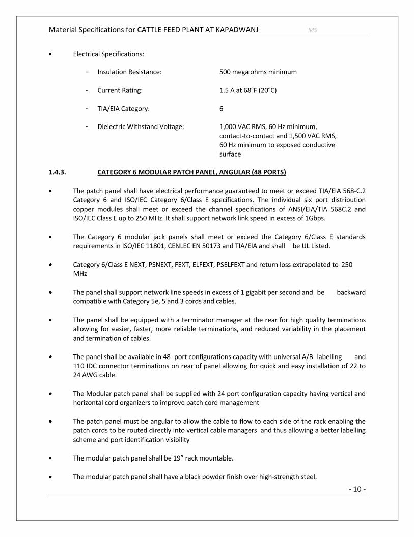
Electrical Specifications:
- Insulation Resistance: 500 mega ohms minimum
- Current Rating: 1.5 A at 68°F (20°C)
- TIA/EIA Category: 6
- Dielectric Withstand Voltage: 1,000 VAC RMS, 60 Hz minimum, contact-to-contact and 1,500 VAC RMS, 60 Hz minimum to exposed conductive surface
1.4.3. CATEGORY 6 MODULAR PATCH PANEL, ANGULAR (48 PORTS)
The patch panel shall have electrical performance guaranteed to meet or exceed TIA/EIA 568-C.2 Category 6 and ISO/IEC Category 6/Class E specifications. The individual six port distribution copper modules shall meet or exceed the channel specifications of ANSI/EIA/TIA 568C.2 and ISO/IEC Class E up to 250 MHz. It shall support network link speed in excess of 1Gbps.
The Category 6 modular jack panels shall meet or exceed the Category 6/Class E standards requirements in ISO/IEC 11801, CENLEC EN 50173 and TIA/EIA and shall be UL Listed.
Category 6/Class E NEXT, PSNEXT, FEXT, ELFEXT, PSELFEXT and return loss extrapolated to 250 MHz
The panel shall support network line speeds in excess of 1 gigabit per second and be backward compatible with Category 5e, 5 and 3 cords and cables.
The panel shall be equipped with a terminator manager at the rear for high quality terminations allowing for easier, faster, more reliable terminations, and reduced variability in the placement and termination of cables.
The panel shall be available in 48- port configurations capacity with universal A/B labelling and 110 IDC connector terminations on rear of panel allowing for quick and easy installation of 22 to 24 AWG cable.
The Modular patch panel shall be supplied with 24 port configuration capacity having vertical and horizontal cord organizers to improve patch cord management
The patch panel must be angular to allow the cable to flow to each side of the rack enabling the patch cords to be routed directly into vertical cable managers and thus allowing a better labelling scheme and port identification visibility
The modular patch panel shall be 19” rack mountable.
The modular patch panel shall have a black powder finish over high-strength steel.

Material Specifications for CATTLE FEED PLANT AT KAPADWANJ MS
- 11 -
The modular patch panel shall accept six-port distribution copper modules. ( 8 Nos. x 6-port modules in full loaded condition or lower as necessary)
The six port distribution copper module shall have 110 connector terminations on rear for termination of 22 to 24 AWG cable.
All plastic components of patch panel and distribution module shall be made of high impact plastics and shall be UL and cUL listed.
All components shall be manufactured by single manufacturer. The manufacturer shall warrant the Category 6 channel cable, components, and applications for a period of 20 years.
Blanking panel shall be provided to protect unused slots of patch panel from the entry of dust and deterrents
Physical Specifications:
- 24 Port: H x W x D: 1.74 inch x 19 inch x 1.6 inch
- 48 Port: H x W x D: 3.50 inch x 19 inch x 1.6 inch
- Plastic Material: High-impact, flame retardant, thermoplastic
- Flammability Rating: UL-rated 94 V-0
- Operating Temperature: 14°F to 140°F (-10°C to 60°C)
- Storage Temperature: -40°F to 158°F (-40°C to 70°C)
- Humidity: 95% (non-condensing)
Contact Material & Plating: Copper alloy, 100 micro-inch bright solder over 100 micro-inch nickel under plate. Insulation displacement connectors accept solid or stranded wire
Nominal Solid Conductor Diameter: 0.40 mm to 0.64 mm (26 to 22 AWG)
Nominal Stranded Conductor Dia.: 0.51 mm to 0.64 mm (24 to 22 AWG)
Insulation Size: 0.76 mm to 1.17 mm
Insulation Types: All plastic insulates, including: PVC, irradiated PVC, Polyethylene, Polypropylene,

Material Specifications for CATTLE FEED PLANT AT KAPADWANJ MS
- 12 -
PTFE, Polyurethane, Nylon and FEP
Outlet Wires: Copper alloy, 50 micro-inch hard gold plating over 100 micro-inch nickel under plate.
Plug Retention Force: 133 N minimum between modular plug and jack
Plug Insertion Life: 750 minimum insertions of an 8-position IEC 60603-7 compliant plug
Plug/Jack Contact Force: 100 grams minimum per contact using FCC approved plug
Electrical Specifications:
- Insulation Resistance: 500 mega ohms minimum
- Current Rating: 1.5 A at 68°F (20°C)
- TIA/EIA Category: 6
- Dielectric Withstand Voltage: 1,000 VAC RMS, 60 Hz minimum, contact-to-contact and 1,500 VAC RMS, 60 Hz minimum to exposed conductive surface
1.4.4. CATEGORY 6 INFORMATION OUTLET (IO)
Category 6 IOs shall meet or exceed Category 6 transmission requirements for connecting hardware, as specified in TIA/EIA 568-B Commercial Building Telecommunications Cabling Standard and ISO/IEC 11801:2002 Second Edition, CENELEC EN 50173, and TIA/EIA568C.2
The Category 6 IOs shall be backward compatible with Category 5E, 5 and 3 cords and cables.
The Category 6 IOs shall be of a universal design supporting T568 A & B wiring.
The Category 6 IOs shall be either a part modular patching situation or as a modular telecommunication outlet (TO) supporting current 10BASE-T, Token Ring, 100 Mbps TP-PMD, 155 Mbps ATM, 622 Mbps ATM using parallel transmission schemes and evolving high-speed, high-bandwidth applications, including Ethernet, 1000BASE-T/Tx and 1.2 Gbps ATM.
Category 6 IOs shall have improved pair splitters and wider channel for enhanced conductor placement. The outlet shall also have a low-profile wire cap, which protects against contamination and secures the connection. Multicolored identification labels shall be available to assure accurate installation.

Material Specifications for CATTLE FEED PLANT AT KAPADWANJ MS
- 13 -
As an option, the Category 6 IOs shall be capable of being installed at either a 45o or a 90 o angle in any modular faceplate, frame, or surface-mounted box avoiding the need for special faceplates by using matching suitable components
TIA Category 6/ISO Class E NEXT, PSNEXT, FEXT, ELFEXT, PSELFEXT and return loss extrapolated to 250 MHz.
The Category 6 IOs shall be available in at least 3 colours for identification with different applications such as Data, Voice, IP voice etc.
The category 6 IOs shall allow universal A/B type wiring and labeling.
The Category 6 outlets shall be capable of being installed at either a 45 or a 90 angle in same manufacturer supplied modular faceplate, frame, or surface-mounted box avoiding the need for special faceplate.
The Category 6 outlets shall have improved pair splitters and wider channel for enhanced conductor placement. The outlet shall also have a low-profile wire cap, which protects against contamination and secures the connection. Multicolored identification labels shall be available to assure accurate installation.
The Category 6 IOs shall be made from high impact thermoplastic and shall be ULand c UL rated.
The Insulation Displacement connectors must accept solid as well as stranded wire.
Physical Specifications:
- Dimensions: H x W x D: 2.0 cm x 2.0 cm x 3.1 cm
- Plastic Material: High-impact, flame retardant, thermoplastic
- Flammability Rating: UL-rated 94 V-0
- Contact Material: Copper Alloy
- Plating: Gold over nickel
- Nominal Solid Conductor Diameter: 0.40 mm to 0.64 mm (26 to 22 AWG)
- Nominal Stranded Conductor Diameter: 0.51 mm to 0.64 mm (24 to 22 AWG)
- Insulation Size: 0.76 mm to 1.17 mm

Material Specifications for CATTLE FEED PLANT AT KAPADWANJ MS
- 14 -
- Insulation Types: All plastic insulates, including: PVC, irradiated PVC, Polyethylene, Polypropylene, PTFE, Polyurethane, Nylon and FEP
Electrical Specifications:
- Insulation Resistance: 500 mega ohms minimum
- Current Rating: 1.5 A at 68°F (20°C)
- TIA/EIA Category: 6
- Dielectric Withstand Voltage: 1,000 VAC RMS, 60 Hz minimum, contact-to-contact and 1,500 VAC RMS, 60 Hz minimum to exposed conductive surface
1.4.5. FACE PLATE FOR INFORMATION OUTLET (SINGLE / DUAL)
Faceplate should contain slots that cover the screws to house labels and covers.
Labels and covers should be included with the face plate as required.
Faceplate outlet opening should be numbered on both sides for installation & maintenance identification.
Should have provision of blank to fill the unused outlet openings.
Should be made from high impact, flame retardant, UL rated 94 V-0 thermoplastic.
The modular face plate shall be used to mount or install CAT 6 information outlets.
The modular shall be available in single, dual and quad arrangement in single gang.
All faceplates material (Plastic) shall meet the specifications of High-impact, flame retardant, UL-rated 94 V-0, thermoplastic. The dimensions shall be co-ordinate with project authorities as per actual site requirements.
1.4.6. 19” WALL MOUNTED NETWORKING RACK – 12U – GENERAL SPECS
Construction shall be single Section welded robust with ventilation holes on the sides and top & bottom covers with provision to mount 2 fans
Top/ Bottom Covers and Side panels shall be of sheet steel and powder coated
Vertical 19” metric panel mounts and door trims shall be of sheet steel and powder coated

Material Specifications for CATTLE FEED PLANT AT KAPADWANJ MS
- 15 -
The top and bottom covers shall be provided with 35mm round cuts for cable entry and round cuts shall be edge protected with rubber grommets
Two pairs of 19” Equipment mounting angles with mounting holes conforming to IEC 297- 3
Toughened glass front lockable door
Swinging door on hinges from left to right
Wall mounted 19” Networking rack shall be available in various heights
Cooling shall be achieved with the help of two fans, 90 CFM capacity each, mounted on top
Power - Power shall be provided in form 19” rack mountable power strip which shall consist of minimum four 5/15A power sockets. Power strip shall be provided with 20A MCB
Cantilever Shelf – One number of front mounting 1U cantilever shelf shall be provided
Stationery Shelf – One Number Stationery Shelf shall be provided for installing network equipment such as 16/24 port switch
1U vertical cable managers on A/R (As Required Basis) for dressing of cables for 24 ports patch panel, 24 ports switch
Hardware Pack / Rack mounting accessories and hardware A/R
Horizontal managers on A/R basis for ensuring neat and aesthetically clean installation
Cabinet material – cabinet shall be made of 14 Gauge (2mm) thick cold rolled steel sheets or thicker
Finish – cabinet shall be black or grey epoxy powder-coated of durable quality
Load carrying capacity – min. 25 kg load of equipments should be mountable
Product must be UL listed and certified for use in Information Technology or Communication Equipment
EIA standard pattern design with 12-24 tapped holes (EIA-310-E compliant)
Dimensions – at least 15U usable height, 600mm (W), 450mm(D)
The Metal Enclosures/Racks must have unit prices for its individual knocked down items such as - 15U x 600mmW x 450mmD main frame, glass front door, perforated/vented steel rear door, vented side panels (2), 2 x 90cfm fans tray and fans, 1x5A/15A power strip, 1U Cable Manager,

Material Specifications for CATTLE FEED PLANT AT KAPADWANJ MS
- 16 -
Sliding Shelf, Rotating Shelf, Cantilever Shelf, Heavy Duty Stationery Shelf, Castors, Vertical manager/runner, hardware and any other such accessory. It must be possible to configure the enclosure as per specific needs for a customized installation for every rack.
1.4.7. 19” FLOOR STANDING NETWORKING ENCLOSURES (22U TO 42U USABLE HEIGHTS)
Construction shall be high strength robust aluminum extruded frame structure with ventilation slots on the sides and top & bottom covers with provision to mount 4 fans on top cover (The Vertical Profiles which forms the frame of the racks are extruded Aluminum type).
The Other parts / components except the Vertical Profiles are made of CRCA Steel.
CRCA steel used is “IS 513 Gr D” standard
The Thickness of the CRCA sheets used for Doors is 1.2mm and foe Side Panels is 1mm.
Fully adjustable 19” equipment mounting angles
The cabinet shall be made of high impact CRCA steel as per IS 513 Gr D standard and design confirming to DIN 41494 or EIA 310D standards.
Top/ Bottom Covers and Side panels shall be of sheet steel and powder coated
Vertical 19” metric panel mounts and door trims shall be of sheet steel and powder coated
The top and bottom covers shall be provided with number of 50mm and 75mm round cable knockouts for cable entry and cable knockouts shall be edge protected with rubber grommets.
Perforation - for full / split perforated doors the style should be ” Honeycomb” type of perforation for maximum air circulation and stiffness .The perforation area should be 70% of the total door area.
Cabinet can be capable of dismantling and reassemble at the site.
Locks Options – options shall be available such as slam lock - common key or unique key, Swing handle lock, Digital Keypad operated locks, Biometric locks.
Side Panels – must contain slam latches for locking purpose and option of providing slam locks, if required.
Two pairs of 19” Equipment mounting angles with mounting holes conforming to IEC 2973
Front Glass door made of toughened glass, tinted with easily detachable hinges.
Two Pair of slotted vertical cable channel shall be provided at front and back for managing cables
Material Specifications for CATTLE FEED PLANT AT KAPADWANJ MS
- 17 -
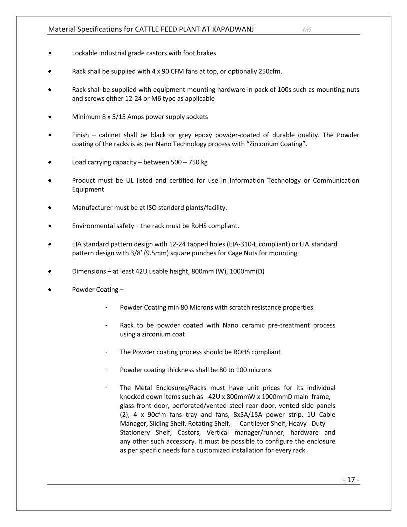
Lockable industrial grade castors with foot brakes
Rack shall be supplied with 4 x 90 CFM fans at top, or optionally 250cfm.
Rack shall be supplied with equipment mounting hardware in pack of 100s such as mounting nuts and screws either 12-24 or M6 type as applicable
Minimum 8 x 5/15 Amps power supply sockets
Finish – cabinet shall be black or grey epoxy powder-coated of durable quality. The Powder coating of the racks is as per Nano Technology process with “Zirconium Coating”.
Load carrying capacity – between 500 – 750 kg
Product must be UL listed and certified for use in Information Technology or Communication Equipment
Manufacturer must be at ISO standard plants/facility.
Environmental safety – the rack must be RoHS compliant.
EIA standard pattern design with 12-24 tapped holes (EIA-310-E compliant) or EIA standard pattern design with 3/8’ (9.5mm) square punches for Cage Nuts for mounting
Dimensions – at least 42U usable height, 800mm (W), 1000mm(D)
Powder Coating –
- Powder Coating min 80 Microns with scratch resistance properties. - Rack to be powder coated with Nano ceramic pre-treatment process using a zirconium coat - The Powder coating process should be ROHS compliant - Powder coating thickness shall be 80 to 100 microns - The Metal Enclosures/Racks must have unit prices for its individual knocked down items such as - 42U x 800mmW x 1000mmD main frame, glass front door, perforated/vented steel rear door, vented side panels (2), 4 x 90cfm fans tray and fans, 8x5A/15A power strip, 1U Cable Manager, Sliding Shelf, Rotating Shelf, Cantilever Shelf, Heavy Duty Stationery Shelf, Castors, Vertical manager/runner, hardware and any other such accessory. It must be possible to configure the enclosure as per specific needs for a customized installation for every rack.

Material Specifications for CATTLE FEED PLANT AT KAPADWANJ MS
- 18 -
1.4.8. CATEGORY 6 PATCH CORD (3 FEET / 7 FEET)
All patch cords shall exceed TIA/EIA & ISO/IEC Category 6/Class E specifications
Performance guaranteed to meet or exceed the channel specifications of the TIA “Category 6” up to 250 MHz capable of delivering greater than 1Gbps bandwidth on CAT6 channel
Complies Category 6/Class E NEXT, PSNEXT, FEXT, ELFEXT, PSELFEXT and return loss extrapolated to 250 MHz
Cat 6A patch cords shall be 4-pair Unshielded Twisted Pair (UTP), round construction, with a bisector tape in the core, available in PVC, LSZH and Plenum versions with plugs compliant with IEC 60603-7-4
The patch cords shall be factory terminated with matching CAT6 plugs or connectors
The patch cords shall incorporate an anti-snag feature that provides maximum protection from snagging during moves and re arrangements
Patch cords shall be UL listed, UL-C certified
Patch cords shall be available in stranded and solid conductor in lengths to 100 feet
All patch cords shall be backward compatible with Category 5 and Category 5E systems
Physical Specifications:
- Contact Material: Phosphor Bronze
- Contact Plating: a combination of Gold & Nickel
- Insertion Life: 750 events minimum
- Plug Material: Polycarbonate UL-rated 94 V-O
1.5. DATA NETWORKING - FIBER OPTIC CABLE AND COMPONENTS 1.5.1. OUTDOOR SM FIBER OPTIC CABLE
12 Core Outdoor SM Fiber Optic cable, All Di-Electric, Outdoor Loose Tube All Dry Cable
The SM Zero water peak (Gel free – All dry) fiber cables shall be dispersion-unsuited fiber which meets the ITU-T G.652.D requirements.
The SM fiber shall be fully capable of handling existing and legacy SM applications which traditionally operate in the 1310 nm and 1550 nm regions.

Material Specifications for CATTLE FEED PLANT AT KAPADWANJ MS
- 19 -
The fiber cable shall be designed to handle the new and emerging applications that utilize the "Extended" E-band; 1360-nm to 1460nm has ZERO WATER PEAK in this operating window.
The fiber cable shall also be designed to provide optimum performance across the entire frequency spectrum - from 1260nm to 1620nm making it suitable for Coarse Wavelength Division Multiplexing (CWDM) applications
The cable core shall be water blocked with dry water-blocking materials, making access and handling of individual tubes easier and craft-friendly
SM fiber should be completely gel-free all dry cable, so as to avoid use of solvents and chemicals during splicing and preparation of fiber cores for termination.
The fiber optic cable shall have 12 cores.
SM fiber optic cable shall support 10G, 1G and 100Mbps LAN applications for minimum distance to 2KMs
Fiber cable shall support the use of ST, STII, SC as well as high-density LC connectors/couplers
All the fiber cores shall be colour coded as per industry standards For the installed channel a minimum 20 year extended product warranty and application assurance has to be provided Physical Characteristics:
Nominal Cable Outside Diameter 0.41 in (10.5 mm) Cladding Diameter 1 25.0 ± 0.7 μm Core/Clad Offset ≤ 0.5 μm Coating Diameter (Uncolored) 245 ± 10 μm Coating Diameter (Colored) 254 ± 7 μm Coating/Cladding Concentricity Error 12 μm maximum Clad Non-Circularity ≤ 1%
Optical Performance Parameters 1310 nm 1385 nm 1550 nm
Max. Attenuation, Loose Tube Cable 0.34 dB/km 0.31 dB/km 0.22 dB/km
Max. Attenuation, Tight Buffer Cable 0.70 dB/km 0.70 dB/km 0.70 dB/km
Mode Field Diameter in um 9.2 ± 0.3 9.6 ± 0.6 1 0.4 ± 0.5
Group Refractive Index 1.466 1.466 1.467
1.5.2. WALL MOUNTED FIBER OPTIC LIU
The fiber optic distribution (LIU) shall be a wall mounted unit with optional brackets/accessories for rack mounting arrangement

Material Specifications for CATTLE FEED PLANT AT KAPADWANJ MS
- 20 -
The LIU shall be usable for a combination of splicing and termination of fiber-optic building cable (indoor) or outside plant (OSP, outdoor) cables with suitable addition of components if required
It should provide for mounting of adaptors panels on which adaptors or couplers can be mounted
It should support provisioning of LC, STII as well as SC type of adaptors and matching panels
The shelf shall be primarily used for accommodating up to 6 fusion splices having LC components for 12 cores per LIU. It must be supplied with LC adaptor panels for 12 ports
A splicing kit or holder must be provided for housing the fusion splices with pigtails and individual fiber cores for holding and proper management of slack length
Every core entering inside the LIU must be spliced – there should be no free/un-mounted/un-spliced cores inside the LIU
The quality, make and type of adaptors used in the LIU must complement the main specification of the fiber optic cable to be terminated inside the LIU
The LIU must have adequate entrance holes such that fiber optic cable can be brought in without comprising the minimum bending radius.
1.5.3. DUPLEX LC SM PIGTAILS AND PATCH CORDS
Individual SM fibers shall be terminated in 1U Combination Shelf by fusion splicing of fiber cores to duplex LC SM pigtails
Pigtails/Patch Cords shall be with colorized 0.9mm tight-buffered cordages as per TIA norms
The duplex Pigtails/Patch Cords shall be available in various lengths, minimum being 1mtr length
Type of termination for pigtails shall be LC, and that for patch cord shall be LC-LC
The quality, make and type of pigtails and patch cords used must complement the main specification of the fiber optic cable to be terminated inside the LIU such as the core diameter, whether SM or MM.
1.5.4. SINGLEX / DUPLEX LC FIBER OPTIC COUPLERS – SM
Duplex LC Fiber Optic couplers shall be used in conjunction with front faceplate to ensure proper alignment of the fibers when mating two connectors.
Duplex LC Fiber Optic Coupler shall accept the multi mode fiber connectors and shall be colour coded as per industry standard for identification.

Material Specifications for CATTLE FEED PLANT AT KAPADWANJ MS
- 21 -
Duplex LC Fiber Optic Coupler shall be with dust protection cover.
The quality, make and type of pigtails and patch cords used must complement the main specification of the fiber optic cable to be terminated inside the LIU such as the core diameter, whether SM or MM.
1.6. ACTIVE COMPONENTS-DATA NETWORKING SWITCHES 1.6.1 SPECIFICATION FOR LAYER 2 48 PORT GIGABIT MANAGED SWITCH WITH GBIC PORTS
(NON-Poe) A. PORTS:
1. Switch shall support maximum of 50-port 10/100/1000T ports. 2. Shall support 4 Shared SFP slots to load 1000T / 1000SX/
1000LX/1000LHX/1000ZX ports 3. Shall support Maximum of 4 # 100FX ports without using External media
converter. 4. All the 50 # Gigabit ports should operate simultaneously at any point of time.
B. TRANSMISSION METHOD:
1. Store and forward switching
C. PERFORMANCE:
1. Should support a minimum back plane bandwidth of 108 Gbps with the available
2. Should support a minimum throughput of 74.4Mpps 3. Provides 8 trunk groups of up to 8 member ports 4. Should be stackable in nature. 5. Should support atleast 24 units per stack. 6. Should support single IP Management. 7. Should support IPv6 Ready features with dual stack. 8. Should support DHCP snooping/relay/optional 82/server for IPv4 and IPv6 9. Should support Sflow
D. VLAN:
1. IEEE 802.1Q VLAN tagging 2. Should support Port based and Private VLAN 3. Should support GVRP 4. Support 255 LAN groups and 4K VLAN IDs

Material Specifications for CATTLE FEED PLANT AT KAPADWANJ MS
- 22 -
E. MULTICAST:
1. Should support IGMP v1/v2/v3 Snooping
F. SECURITY:
1. IEEE 802.1x 2. Support 802.1X and MAC based authentication and IP+MAC+VID binding for
different access clients 3. Support management control by AAA and CPU processed traffic control 4. User Authentication using standard based RADIUS server 5. ACL to restrict access to sensitive network resources.
G. QUALITY OF SERVICE:
1. Should support for IEEE 802.1p CoS 2. Classification of information in the MAC, IP, and TCP/UDP headers 3. IEEE 802.1P priority Queuing. 4. Should support 8 priority queues. 5. Should support Diffserv 6. Should Support SP, WRR, SWRR 7. Should support hybrid queuing with SP+WRR 8. IPv6 DSCP
H. IPV6 FEATURES
1. IPv4/IPv6 Dual Protocol Stack 2. IPv6 unicast address types 3. IPv6 multicast address types 4. ICMPv6 RFC 2463 5. IPv6 Neighbour discovery protocol 6. ICMPv6 Redirect 7. IPv6 Stateless Auto Configuration as per RFC2462 8. IP Version 6 Addressing Architecture (RFC2373) 9. Transmission of IPv6 Packets over Ethernet Networks (RFC2464) 10. MLD v1/v2 Snooping 11. SNMP over IPv6 12. HTTP over IPv6 13. IPv6 SNTP support 14. IPv6 Telnet support 15. IPv6 ACL
I. STANDARDS:
1. IEEE 802.3 2. IEEE 802.3u

Material Specifications for CATTLE FEED PLANT AT KAPADWANJ MS
- 23 -
3. IEEE 802.3z 4. IEEE 802.3x 5. IEEE 802.1p 6. IEEE 802.1Q 7. IEEE 802.3ad 8. IEEE 802.1D 9. IEEE 802.1s 10. IEEE 802.1w 11. IEEE 802.1x
J. CONFIGURATION AND MANAGEMENT:
1. SNMP Management 2. Web Management 3. Command Line Interface (CLI) 4. RS-232 console 5. LEDs for diagnostics 6. OEM should have a toll free no 7. OEM Should have service center in India. 8. OEM should have direct presence in India atleast for 10 Years. 9. OEM should have ISO 14001 Certificate.
1.6.2 SPECIFICATION FOR LAYER 2 24 PORT GIGABIT MANAGED SWITCH WITH GBIC PORTS (NON PoE)
A. PORTS:
1. Switch shall support maximum of 26-port 10/100/1000T ports. 2. Shall support 4 Shared SFP slots to load 1000T / 1000SX/ 1000LX/1000LHX/1000ZX ports. 3. All 26 # Fast Ethernet ports should operate simultaneously at any point of time.
B. TRANSMISSION METHOD:
1. Store and forward switching C. PERFORMANCE:
1. Should support a minimum back plane bandwidth of 12.8 Gbps with the available. 2. Should support a minimum throughput of 6.6Mpps. 3. Provides 8 trunk groups of up to 8 member ports. 4. Should be stackable in nature. 5. Should support single IP Management. 6. Should support IPv6 Ready features with dual stack. 7. Should support DHCP snooping/relay/optional 82/server for IPv4 and IPv6 8. Should support Sflow

Material Specifications for CATTLE FEED PLANT AT KAPADWANJ MS
- 24 -
D. VLAN:
1. IEEE 802.1Q VLAN tagging 2. Should support Port based and Private VLAN 3. Should support GVRP 4. Support 255 LAN groups and 4K VLAN IDs
E. MULTICAST:
1. Should support IGMP v1/v2/v3 Snooping
F. SECURITY:
1. IEEE 802.1x 2. Support 802.1X and MAC based authentication and IP+MAC+VID binding for different access
clients 3. User Authentication using standard based RADIUS server
G. QUALITY OF SERVICE:
1. Should support for IEEE 802.1p CoS 2. Classification of information in the MAC, IP, and TCP/UDP headers 3. IEEE 802.1P priority Queuing. 4. Should support 8 priority queues. 5. Should support Diffserv 6. Should Support SP, WRR, SWRR
H. STANDARDS:
1. IEEE 802.3 2. IEEE 802.3u 3. IEEE 802.3z 4. IEEE 802.3x 5. IEEE 802.1p 6. IEEE 802.1Q 7. IEEE 802.3ad 8. IEEE 802.1D 9. IEEE 802.1s 10. IEEE 802.1w 11. IEEE 802.1x
I. CONFIGURATION AND MANAGEMENT:
1. SNMP Management 2. Web Management 3. Command Line Interface (CLI) 4. RS-232 console

Material Specifications for CATTLE FEED PLANT AT KAPADWANJ MS
- 25 -
5. LEDs for diagnostics 6. OEM should have a toll free no 7. OEM Should have service center in India. 8. OEM should have direct presence in India at least for 10 Years. 9. OEM should have ISO 14001 Certificate.

Material Specifications for CATTLE FEED PLANT AT KAPADWANJ MS
- 26 -
1.7. EPABX SYSTEM AND SPECIFICATIONS 1.7.1 Design:
The supplied EPABX system shall include all components such as hardware, interfaces and licences for netlink based connectivity with other sites/locations of the client.
The system design should be Digital, Non Blocking supporting Analog ,Digital and IPEnd terminals.
The System should support Analog, ISDN, VoIP & SIP Trunks as well as Extensions.
Expandability / Maximum Capacities shall be as follows:
- 80 Extensions, with at least 50% expansions capacity.
- 8 IP End Points (licensing)
- 2 ISDN PRI interfaces, 4 analog trunks
The system should be 19” rack mountable.
The system should have modular design for Trunks and Extensions.

Material Specifications for CATTLE FEED PLANT AT KAPADWANJ MS
- 27 -
2. PUBLIC ADDRESS SYSTEM
2.1 Central Controller:
Features:
The Controller should have the following Features and Functions: -
- Should support minimum Six-zone
- Should have Built-in 240 amplifier
- Business and emergency control inputs
- The controller should be EN 54‑16 and EN 60849 compliant
Functions:
- The controller should have two BGM source inputs and a mic/line input with configurable
priority, speech filter & phantom power. The controller should have 16 priority levels can be
specified for microphone, call stations and trigger inputs for optimum system flexibility.
- The amplifier 240 W output section should have six transformer-isolated 100 V constant voltage
outputs for driving 100 V loudspeakers in six separate zones. The 100 V selections shall be
provided to reduce line losses on longer distances and for providing easy parallel connection of
multiple loudspeakers. The controller should have zone selection from the front panel, and the
BGM output level in each zone can be individually set in six steps. The controller should support
A/B wiring.
- Configuration software should be provided on the CD included with the unit. The CD shall also
include other useful programs, such as MP3-ripping software, a sample-rate converter, various
audio and visual tools, and free, MP3-coded music.
- The amplifier output must be available as a separate output on 100 V and 70 V. A separate 100
V call-only output provides addressing for an area where BGM is not required but where priority
announcements are necessary. Six configurable volume-override output contacts should be
available for overriding local volume controls during priority calls. The Controller should support
both four-wire and three-wire schemes. There should be LED meter for monitoring the output.
- The Controller should support storage of 255 messages internal 8/16/32 MB Flash ROM, without
a need for battery backup. Message can have any length within the total available capacity.
Messages and configurations should be uploaded from a PC via USB 2 into the memory, after
which the unit operates without a PC connection. The messages should be in standard WAV

Material Specifications for CATTLE FEED PLANT AT KAPADWANJ MS
- 28 -
format and sample rates of 8 kHz up to 24 kHz with 16-bit word length (linear PCM) which would
give upto 17 minutes of recording time with CD-quality signal-to-noise ratio.
- The unit should have 12 contact trigger inputs for business and emergency (EMG) calls. Each
input shall be configured for a message consisting of a sequence of up to eight wave files. It shall
be possible that some wave files may be used in various combinations with other messages,
optimizing flexibility and the amount of storage space used. Controller should have facility of
Multiple messages merged to form one integrated message.
Technical Specifications:
- Electrical
Mains power supply Voltage: 230/115VAC, ±15%, 50/60 Hz Current inrush: 8 A Max power consumption: 600 VA Battery power supply Voltage: 24 VDC, +15% / -15% Current max: 14 A Performance Output power (rms/maximum): 240 W / 360 W Power reduction on backup power: -1 dB Frequency response: 60 Hz to 18 kHz (+1/-3 dB at -10 dB ref. rated output) Distortion: <1% at rated output power, 1 kHz Bass control: -8/+8 dB at 100 Hz Treble control: -8/+8 dB at 10 kHz Mic/line input: 1 x Connector: XLR, 6.3 mm jack Sensitivity: 1 mV (mic), 1 V (line) Impedance: >1 kohm (mic); >5 kohm (line)

Material Specifications for CATTLE FEED PLANT AT KAPADWANJ MS
- 29 -
S/N (flat at max volume: >63 dB (mic); >70 dB (line) S/N (flat at min volme/muted): >75 dB CMRR: >40 dB (50 Hz – 20 kHz) Headroom: >25 dB Speech filter: -3 dB at 315 Hz, high-pass,6 dB/oct Phantom power supply: 12 V (mic mode only) VOX trigger level: -20 dB (100 μV mic / 100 mV line) or via input contact Limiter: Automatic Line input: (BGM and PC call station) Connector: Cinch, stereo converted to mono, unbalanced Sensitivity: 200 mV Impedance: 22 kohm Loudspeaker outputs Connectors: MSTB 2,5 /16-ST, floating 100 V output: 700 W rated per zone Volumes override types: 3-wire, 4-wire (24 V), 4-wire failsafe BGM zone output: 70 / 50 /35 /25 / 18 / 13 V for Attenuation 0 / -3 / -6 / -9 / -12 / -15 dB 120 / 60 / 30 / 15 / 8 /4 W - Power consumption
Mains operation Max power: 550 W -3dB: 440 W -6dB: 340 W Pilot tone*: 136 W Idle: 60 W

Material Specifications for CATTLE FEED PLANT AT KAPADWANJ MS
- 30 -
24 VDC operations Max power: 14.0 A (336 W) -3 dB: 12.5 A (300 W) -6 dB: 9.5 A (228 W) Pilot tone: 2.5 A (60 W) Idle: 0.9 A (22 W) - Mechanical
Dimensions (H x W x D): 144 x 430 x 370 mm (19" wide, 3U high) Weight: Approx. 21.17 kg Mounting: 19”rack Color: Charcoal - Environmental
Operating temperature: -10 ºC to +55 ºC (14 ºF to +131 ºF) Storage temperature: -40 ºC to +70 ºC (-40 ºF to +158 ºF) Relative humidity: <95% Acoustic noise level of fan: <48 dB SPL at 1 m (max output) 2.2 PA Microphone (6 Zone) The call station shall be provided for making a manual or pre-recorded call to any pre-assigned zones or executing a predefined action. The call station shall have one key. The call station shall have a fixed microphone to transmit speech over the network and a press-to-talk key. The call station shall also have a headset socket. Once the headset is connected the microphone will be muted. The unit shall be certified to be compliant to IEC60849 and compliant to other relevant local standards.
a) The call station shall have a speech filter with a cut-off frequency at 340Hz to improve intelligibility and prevent clipping of the audio input on low-frequency signals.
b) The call station unit shall support connection with at least 6 call station keypad units via
serial data communication links. c) The power supply to the call station keypad units shall be provided from the call station.
Material Specifications for CATTLE FEED PLANT AT KAPADWANJ MS
- 31 -
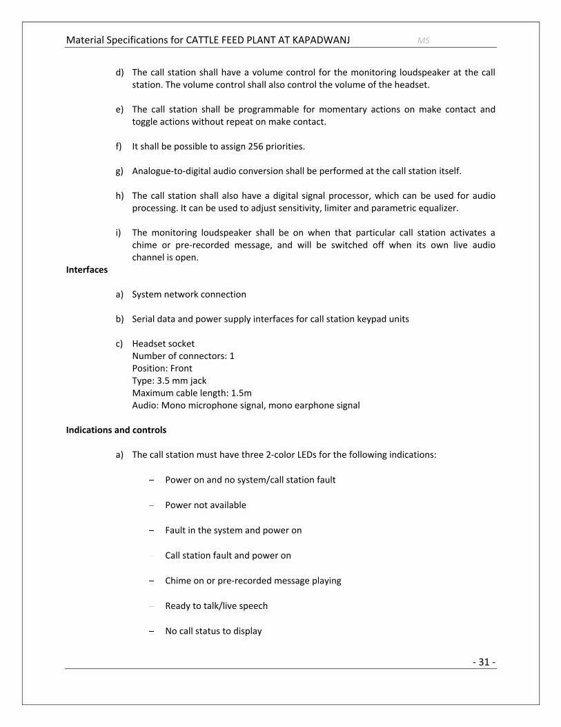
d) The call station shall have a volume control for the monitoring loudspeaker at the call station. The volume control shall also control the volume of the headset.
e) The call station shall be programmable for momentary actions on make contact and
toggle actions without repeat on make contact. f) It shall be possible to assign 256 priorities. g) Analogue-to-digital audio conversion shall be performed at the call station itself. h) The call station shall also have a digital signal processor, which can be used for audio
processing. It can be used to adjust sensitivity, limiter and parametric equalizer. i) The monitoring loudspeaker shall be on when that particular call station activates a
chime or pre-recorded message, and will be switched off when its own live audio channel is open.
Interfaces
a) System network connection
b) Serial data and power supply interfaces for call station keypad units
c) Headset socket Number of connectors: 1 Position: Front Type: 3.5 mm jack Maximum cable length: 1.5m Audio: Mono microphone signal, mono earphone signal
Indications and controls
a) The call station must have three 2-color LEDs for the following indications:
Power on and no system/call station fault
Power not available
Fault in the system and power on
Call station fault and power on
Chime on or pre-recorded message playing
Ready to talk/live speech
No call status to display

Material Specifications for CATTLE FEED PLANT AT KAPADWANJ MS
- 32 -
Emergency announcement is on in the system. Possible to make normal calls to the zones which are not involved (emergency) indication has priority over other indications)
b) Lower-priority calls are on or reserved (to all or some of the pre-assigned zones of the
PTT key of the call station and selected zones of the call station keypad unit if installed)
c) Calls with higher or the same priority (not emergency) are on or reserved (to all or some of the pre-assigned zones of the PTT key of the call station and selected zones of the call station keypad unit if installed)
d) No predefined or selected zones are in use or reserved by the system, nor is an
emergency announcement being made
e) Volume control for loudspeaker/headset 2.3 PA Microphone Keypad – Additional 6 Zones The call station keypad shall be used in combination with the call station basic unit for making a manual or pre-recorded call to any pre-assigned zones or executing a predefined action. The call station keypad shall have 8 keys. The unit shall be certified to be compliant to IEC60849 and compliant to other relevant local standards.
a) The call station keypad keys should be programmable for the following actions:
Control system functions: recall of selection, live speech call, cancel selection, BGM off, BGM volume control, programmable key for any action.
Select resources: BGM selection, pre-recorded message selection, attention and alarm tone selection.
Zone selection, system control output selection.
b) Each key at the call station keypad shall have 2 color LEDs.
c) The call station keypad shall be provided with in and out connections for serial data and power supply.
d) The keys are to be provided with a label slot for indicating the name of the action
assigned to that particular key.
e) The power supply for the call station keypad shall be provided from the call station basic unit.
f) The call station keypad key can be programmed for momentary or toggle operation.
Interfaces
a) Serial data and power supply interfaces for call station keypad units/call station basic.

Material Specifications for CATTLE FEED PLANT AT KAPADWANJ MS
- 33 -
Indications and controls
a) The call station keypad must have one 2-color LED per key for the following indications:
- INDICATION 1..8
a) The selected resources are occupied by a lower-priority call b) The selected resources are occupied by a call with higher or equal
priority. c) The selected resources are available/reserved for executing an action
from that particular station
- KEY 1..8
a) Nothing is active, no LED indication. A function is still active, LED indication is still on.
b) Function(s) is(are) activated, LED indication goes on
2.4 Additional/Power Amplifier:
Features:
- The amplifier should be of 480W rated amplifier
- It should support 70V / 100V and 8 ohm outputs.
- Should support Dual inputs with priority switching.
- 100 V input for slave operation on 100 V speaker line.
- Temperature controlled forced front to back.
- Mains, battery back-up, and pilot tone supervision
- EN 54-16 and EN 60849 compliant.
Functions:
- The unit should operate both on mains power and on a 24 V battery power supply for
emergency back up, with automatic switchover.
- A temperature-controlled fan should be provided for ensuring high reliability at high output
levels and low acoustic noise at lower output levels. An overheat protection circuit switch

Material Specifications for CATTLE FEED PLANT AT KAPADWANJ MS
- 34 -
should be provided for off the power stage and activates an LED on the front panel, if the
internal temperature reaches a critical limit due to poor ventilation or overload.
- For emergency and evacuation use, the following functions should be monitored: mains
presence, battery present, pilot tone presence, amplifier operation. Front panel LEDs indicate
the status of supervised functions.
- The LEDs of pilot tone supervision and battery status can be switched off for general public
address use. Failsafe (normally energized) relays are provided for each supervised function.
These relays are always active regardless of the switches on the rear panel.
Inputs: - - The system should have two balanced inputs with priority control, each with a loop-through
facility, which would make it easy to connect remote systems that require priority control. An
additional 100 V line input should be provided to connect the amplifier to a 100 V loudspeaker
line, to provide more power to remote locations.
- Gain or level control must be located on the rear of the unit to avoid accidental setting change.
A meter with LED-bar shows the output level.
Output: - - The amplifier should have 70 V and 100 V outputs for constant voltage loudspeaker systems and
a low impedance output for 8 ohm loudspeaker loads.
- The Power Amplifier should have two separate priority controlled 100 V outputs for zones that
only need announcements made via the priority input, and for zones that will not get any
announcements made via the priority input.
Technical Specifications:
- Electrical
Mains power supply - Voltage: 230 VAC, ±10%, 50/60 Hz
- Inrush current: 19 A
- Max power consumption: 2200 VA
Battery power supply - Voltage: 24 VDC +15% / -15%
- Current max: 30 A
Performance - Output power (rms/maximum): 480 W / 720 W

Material Specifications for CATTLE FEED PLANT AT KAPADWANJ MS
- 35 -
- Power reduction on backup power: -1 dB
- Frequency response: 50 Hz to 20 kHz (+1/‑ 3 dB @ ‑ 10 dB
ref. rated output)
- Distortion: <1% @ rated output power, 1 kHz
- S/N (flat at max volume): >90 dB
Line inputs: 2X - Connector: 3-pin XLR, balanced
- Sensitivity: 1 V
- Impedance: 20 kohm
- CMRR: >25 dB (50 Hz to 20 kHz)
- Gain: 40 dB
100 V input - Connector: Screw, unbalanced
- Sensitivity: 100 V
- Impedance: 330 kohm
Line loop-through output: 2X - Connector: 3-pin XLR
- Nominal level: 1 V
- Impedance: Direct connection to line input
Loudspeaker outputs: 3X - Connector: Screw, floating
- Direct output: 100 V, 70 V, 8 ohm
- Priority only (from input 1): 100V or 70 V internally selectable
- Music (non-priority) only: 100V or 70 V internally selectable
Power consumption: - Max power: 990 W
- -3dB: 715 W

Material Specifications for CATTLE FEED PLANT AT KAPADWANJ MS
- 36 -
- -6dB: 510 W
- Pilot tone: 110 W
- Idle: 25 W
24 VDC OPERATIONS - Max power: 32 A (770 W)
- -3 dB: 26 A (625 W)
- -6 dB: 18 A (430 W)
- Pilot tone: 3.8 A (91 W)
- Idle: 0.7 A (17 W)
Mechanical:
- Dimensions (H x W x D): 145 x 430 x 370 mm
- Weight Approx.: 25 kg
- Mounting Standalone: 19”rack
Environmental:
- Operating temperature: -10 ºC to +55 ºC (14 ºF to +131 ºF)
- Storage temperature: -40 ºC to +70 ºC (-40 ºF to +158 ºF)
- Relative humidity: <95%
- Acoustic noise level of fan: <48 dB SPL @ 1 m (max output)
2.5 Ceiling Loudspeaker
a) The ceiling loudspeaker must be an economic flush-mounting ceiling loudspeaker for general-purpose applications.
b) The ceiling loudspeaker shall have a single-piece, 6 W, dual-cone loudspeaker with a
100V matching transformer mounted at the back of the frame. It shall have a circular metal grille in the front. The loudspeaker shall have a built-in protection to ensure that, in the event of a fire, damage to the loudspeaker does not result in failure of the circuit to which it is connected.

Material Specifications for CATTLE FEED PLANT AT KAPADWANJ MS
- 37 -
c) The loudspeaker will have ceramic terminal blocks, thermal fuse and heat-resistant, high temperature wiring.
d) Max. Power – 9 W e) Rated Power – 6 Watts f) SPL at 1 KHz, 1m, 1w: 94dB/86 (SPL) g) Rated Voltage: 100 volts h) Rated impedance: 1667 ohms i) Effective frequency range (-10dB) :( 80 Hz to 16000 Hz) j) IEC 60849 compliant system Architect’s and Engineer’s Specifications
2.6 Horn Type Loud Speakers (30 Watt Water Proof)
a) The horn type loudspeakers (30 watt water proof) shall be with two way system,
covering wide range of frequency with a wide dispersion angle for excellent sound and speech reproduction even in the most difficult acoustical environments. Effective frequency range: (70 Hz to 16500 Hz).
2.7 2-Core 1.5 Sq Mm Armored 1-Pair Twisted LS Cable
a) For connecting loudspeakers from power amplifier to power amplifier for zone wise as per tender specification.
2.8 19-Inch Equipment Rack
a) For PA equipment and accessories - controllers, amplifiers, music and BGM sources,, floor mounted, lockable doors etc. being essential features with cooling fans and complete with necessary mounting hardware & accessories. Equipments rack for PA system with provision for mounting of amplifier, controllers etc., self contained with provision for power supply.

Material Specifications for CATTLE FEED PLANT AT KAPADWANJ MS
- 38 -
3. FIRE DETECTION, ALARM AND CONTROL SYSTEM
SYSTEM DESCRIPTION
This section of the specification includes the furnishing, installation, connection and testing of
the microprocessor controlled, intelligent reporting fire alarm equipment required to form a complete, operative, coordinated system. It shall include, but not be limited to, alarm initiating devices, alarm notification appliances, Fire Alarm Control Panel (FACP), auxiliary control devices, annunciators and wiring as shown on the drawings and specified here in.
The fire alarm system shall comply with requirements of NFPA Standard 72/2010. The system
shall be electrically supervised and monitor the integrity of all conductors.
The fire alarm system shall be manufactured by an ISO 9001 certified company and meet the
requirements of BS EN9001: ANSI/ASQC Q9001-1994.
The system and its components shall be listed/certified by Underwriters Laboratories, Inc. listed under the appropriate UL testing standard as listed herein for fire alarm applications and the installation shall be in compliance with the UL listing.
SCOPE
A new intelligent reporting, microprocessor controlled fire detection system shall be installed in accordance to the project specifications and drawings.
Basic Performance
- Alarm, trouble and supervisory signals from all intelligent reporting devices shall be
encoded on NFPA Style 4 (Class B) Signalling Line Circuits.
- Initiation Device Circuits (IDC) shall be wired Class A as part of an addressable device connected by the Loop Circuit.
- Notification Appliance Circuits (NAC) shall be wired Class A as part of an addressable
device connected by the Circuit.
- On Style 6 or 7 (Class A) configurations a single ground fault or open circuit on the system Signalling Line Circuit shall not cause system malfunction, loss of operating power or the ability to report an alarm.
- Alarm signals arriving at the FACP shall not be lost following a primary power failure
(or outage) until the alarm signal is processed and recorded.
Basic system functional operation
When a fire alarm condition is detected and reported by one of the system initiating devices,

Material Specifications for CATTLE FEED PLANT AT KAPADWANJ MS
- 39 -
the following functions shall immediately occur:
- The system alarm LED on the system display shall flash. - A local piezo electric signal in the control panel shall sound.
- A backlit LCD display shall indicate all information associated with the fire alarm
condition including the type of alarm point and its location within the protected premises.
- Printing and history storage equipment shall log the information associated each new
fire alarm control panel condition, along with time and date of occurrence.
- All system output programs assigned via control-by-event interlock programming to be activated by the particular point in alarm shall be executed, and the associated system outputs (notification appliances and/or relays) shall be activated.
APPLICABLE STANDARDS AND SPECIFICATIONS
The specifications and standards listed below form a part of this specification. The system shall fully comply with the latest issue of these standards, if applicable.
National Fire Protection Association (NFPA) - USA: No. 12 CO2 Extinguishing Systems (low and high) No. 12B Halon 1211 Extinguishing Systems No. 13 Sprinkler Systems No. 13A Halon 1301 Extinguishing Systems No. 15 Water Spray Systems No. 16 Foam/Water Deluge and Spray Systems No. 17 Dry Chemical Extinguishing Systems No. 17A Wet Chemical Extinguishing Systems Clean Agent Extinguishing Systems No. 72 National Fire Alarm Code No. 101 Life Safety Code Underwriters Laboratories Inc. (UL) - USA: No. 268 Smoke Detectors for Fire Protective Signalling Systems No. 864 Control Units for Fire Protective Signalling Systems No. 268A Smoke Detectors for Duct Applications No. 521 Heat Detectors for Fire Protective Signalling Systems No. 464 Audible Signalling Appliances No. 38 Manually Actuated Signalling Boxes No. 346 Waterflow Indicators for Fire Protective Signalling Systems No. 1076 Control Units for Burglar Alarm Proprietary Protective Signalling Systems No. 1971 Visual Notification Appliances

Material Specifications for CATTLE FEED PLANT AT KAPADWANJ MS
- 40 -
APPROVALS:
The system shall have proper listing and/or approval from the following nationally recognized agencies:
UL : - Underwriters Laboratories Inc
The fire alarm control panel shall meet UL Standard 864 Ninth Edition (Control Units) and UL Standard 1076 (Proprietary Burglar Alarm Systems).
EQUIPMENT AND MATERIAL, GENERAL
All equipment and components shall be new, and the manufacturer's current model. The materials, appliances, equipment and devices shall be tested and listed by a nationally recognized approvals agency for use as part of a protective signalling system, meeting the National Fire Alarm Code.
All equipment and components shall be installed in strict compliance with manufacturers' recommendations. Consult the manufacturer's installation manuals for all wiring diagrams, schematics, physical equipment sizes, etc., before beginning system installation.
All equipment shall be attached to walls and ceiling/floor assemblies and shall be held firmly in place (e.g., detectors shall not be supported solely by suspended ceilings). Fasteners and supports shall be adequate to support the required load.
CONDUIT AND WIRE
Conduit: - Conduit shall be in accordance with The National Electrical Code (NEC), local and
state requirements.
- Where required, all wiring shall be installed in conduit or raceway. Conduit fill shall not exceed 40 percent of interior cross sectional area where three or more cables are contained within a single conduit.
- Cable must be separated from any open conductors of power, or Class 1 circuits, and shall not be placed in any conduit, junction box or raceway containing these conductors, per NEC Article 760-55.
- Wiring for 24 volt DC control, alarm notification, emergency communication and similar power-limited auxiliary functions may be run in the same conduit as initiating and signalling line circuits. All circuits shall be provided with transient suppression devices and the system shall be designed to permit simultaneous operation of all circuits without interference or loss of signals.
- Conduit shall not enter the fire alarm control panel, or any other remotely - mounted control panel equipment or back boxes, except where conduit entry is
specified by the FACP manufacturer.

Material Specifications for CATTLE FEED PLANT AT KAPADWANJ MS
- 41 -
- Conduit shall be 3/4-inch (19.1 mm) minimum
Wire: - All fire alarm system wiring shall be new. - - Wiring shall be in accordance with local, state and national codes (e.g., NEC Article
760) and as recommended by the manufacturer of the fire alarm system. Number and size of conductors shall be as recommended by the fire alarm system manufacturer, but not less than 18 AWG (1.02 mm) for Initiating Device Circuits and Signalling Line Circuits, and 14 AWG (1.63 mm) for Notification Appliance Circuits.
- All wire and cable shall be listed and/or approved by a recognized testing agency for
use with a protective signalling system.
- Wire and cable not installed in conduit shall have a fire resistance rating suitable for the installation as indicated in NFPA 70 (e.g., FPLR).
- Wiring used for the multiplex communication circuit shall be twisted and unshielded and support a minimum wiring distance of 12,500 feet. The design of the system shall permit use of IDC and NAC wiring in the same conduit with the Loop communication circuit.
- All field wiring shall be electrically supervised for open circuit and ground fault.
- The fire alarm control panel shall be capable of t-tapping Class B Signalling Line Circuits . Systems that do not allow or have restrictions in, for example, the amount of t-taps, length of t-taps etc., are not acceptable.
Terminal Boxes, Junction Boxes and Cabinets:
- All boxes and cabinets shall be UL listed for their use and purpose.
Initiating circuits shall be arranged to serve like categories (manual, smoke, water flow). Mixed category circuitry shall not be permitted except on signalling line circuits connected to intelligent reporting devices.
The fire alarm control panel shall be connected to a separate dedicated branch circuit, maximum 20 amperes. This circuit shall be labelled at the main power distribution panel as FIRE ALARM. Fire alarm control panel primary power wiring shall be 12 AWG. The control panel cabinet shall be grounded securely to either a cold water pipe or grounding rod.

Material Specifications for CATTLE FEED PLANT AT KAPADWANJ MS
- 42 -
3.1 Main fire alarm control panel or network node:
Main FACP or network node shall contain a microprocessor based Central Processing Unit (CPU) and power supply in an economical space saving single board design. The CPU shall communicate with and control the following types of equipment used to make up the system: intelligent addressable smoke and thermal (heat) detectors, addressable modules, printer, annunciators, and other system controlled devices.
Operator Control:
Acknowledge Switch:
- Activation of the control panel acknowledge switch in response to new alarms
and/or troubles shall silence the local panel piezo electric signal and change the alarm and trouble LEDs from flashing mode to steady-ON mode. If multiple alarm or trouble conditions exist, depression of this switch shall advance the LCD display to the next alarm or trouble condition.
- Depression of the Acknowledge switch shall also silence all remote Annunciators
piezo sounders.
Alarm Silence Switch:
- Activation of the alarm silence switch shall cause all programmed alarm notification
appliances and relays to return to the normal condition after an alarm condition. The selection of notification circuits and relays that are silence able by this switch shall be fully field programmable within the confines of all applicable standards. The FACP software shall include silence inhibit and auto-silence timers.
Alarm Activate (Drill) Switch:
- The Alarm Activate switch shall activate all notification appliance circuits. The drill
function shall latch until the panel is silenced or reset.
System Reset Switch:
- Activation of the System Reset switch shall cause all electronically-latched initiating
devices, appliances or software zones, as well as all associated output devices and circuits, to return to their normal condition.
Lamp Test:
- The Lamp Test switch shall activate all local system LEDs, light each segment of the
liquid crystal display and display the panel software revision for service personal.

Material Specifications for CATTLE FEED PLANT AT KAPADWANJ MS
- 43 -
System Capacity and General Operation
The control panel or each network node shall provide, or be capable of supporting upto 636 intelligent/addressable devices.
The control panel or each network node shall include Form-C alarm, trouble, supervisory, and security relays rated at a minimum of 2.0 amps @ 30 VDC.
It shall also include four Class B (NFPA Style Y) or Class A (NFPA Style Z) programmable Notification Appliance Circuits.
The system shall include a full featured operator interface control and annunciation panel that shall include a backlit Liquid Crystal Display (LCD), individual colour coded system status LEDs, and an alphanumeric keypad with easy touch rubber keys for the field programming and control of the fire alarm system.
The system shall allow the programming of any input to activate any output or group of outputs. Systems that have limited programming (such as general alarm), have complicated programming (such as a diode matrix), or require a laptop personal computer are not considered suitable substitutes.
The FACP shall support up to 20 logic equations, including "and," "or," and "not," or time delay equations to be used for advanced programming. Logic equations shall require the use of a PC with a software utility designed for programming.
The FACP or each network node shall provide the following features:
- Drift compensation to extend detector accuracy over life. Drift compensation shall also include a smoothing feature, allowing transient noise signals to be filtered out.
- Detector sensitivity test, meeting requirements of NFPA 72.
- Maintenance alert, with two levels (maintenance alert/maintenance urgent), to warn
of excessive smoke detector dirt or dust accumulation.
- Nine sensitivity levels for alarm, selected by detector. The alarm level range shall be
.5 to 2.35 percent per foot for photoelectric detectors and 0.5 to 2.5 percent per foot for ionization detectors. The system shall also support sensitive advanced detection laser detectors with an alarm level range of .03 percent per foot to 1.0 percent per foot. The system shall also include up to nine levels of Prealarm, selected by detector, to indicate impending alarms to maintenance personnel.
- The ability to display or print system reports.
- Alarm verification, with counters and a trouble indication to alert maintenance
personnel when a detector enters verification 20 times.

Material Specifications for CATTLE FEED PLANT AT KAPADWANJ MS
- 44 -
- PAS pre signal meeting NFPA 72 requirements.
- Rapid manual station reporting (under 3 seconds) and shall meet NFPA 72
requirements for activation of notification circuits within 10 seconds of initiating device activation.
- Periodic detector test, conducted automatically by the software.
- Self optimizing pre-alarm for advanced fire warning, which allows each detector to
learn its particular environment and set its pre alarm level to just above normal peaks.
- Cross zoning with the capability of counting: two detectors in alarm, two software
zones in alarm, or one smoke detector and one thermal detector.
- Walk test, with a check for two detectors set to same address.
- Control-by-time for non-fire operations, with holiday schedules.
- Day/night automatic adjustment of detector sensitivity.
- Device blink control for sleeping areas.
The FACP shall be capable of coding main panel node notification circuits in March Time
(120 PPM), Temporal (NFPA 72 A-2-2.2.2), and California Code. Panel notification circuits (NAC 1,2,3 and 4) shall also support Two-Stage operation, Canadian Dual Stage (3 minutes) and Canadian Dual Stage (5 minutes). Two stage operation shall allow 20 Pulses Per Minute (PPM) on alarm and 120 PPM after 5 minutes or when a second device activates. Canadian Dual stage is the same as Two-Stage except will only switch to second stage by activation of Drill Switch 3 or 5 minute timer. The panel shall also provide a coding option that will synchronize specific strobe lights designed to accept a specific "sync pulse.”
Network Communication
- The FACP shall be capable of communicating on a Local Area Network (LAN), a firmware package that utilizes a peer-to-peer, inherently regenerative communication format and protocol.
Central Microprocessor
- The microprocessor shall be a state-of-the-art, high speed, 16-bit RISC device and it shall communicate with, monitor and control all external interfaces. It shall include an EPROM for system program storage, Flash memory for building-specific program storage, and a "watch dog" timer circuit to detect and report microprocessor failure.

Material Specifications for CATTLE FEED PLANT AT KAPADWANJ MS
- 45 -
- The microprocessor shall contain and execute all control-by-event programs for
specific action to be taken if an alarm condition is detected by the system. Control-by-event equations shall be held in non-volatile programmable memory, and shall not be lost even if system primary and secondary power failure occurs.
- The microprocessor shall also provide a real-time clock for time annotation of system
displays, printer, and history file. The time-of-day and date shall not be lost if system primary and secondary power supplies fail. The real time clock may also be used to control non-fire functions at programmed time-of-day, day-of-week, and day-of-year.
- A special program check function shall be provided to detect common operator
errors.
- An auto-program (self-learn) function shall be provided to quickly install initial
functions and make the system operational.
- For flexibility and to ensure program validity, an optional Windows(TM) based
program utility shall be available. This program shall be used to off-line program the system with batch upload/download, and have the ability to upgrade the manufacturers (FLASH) system code changes. This program shall also have a verification utility, which scans the program files, identifying possible errors. It shall also have the ability to compare old program files to new ones, identifying differences in the two files to allow complete testing of any system operating changes. This shall be in incompliance with the NFPA 72 requirements for testing after system modification.
System Display
The system shall support the following display mode option.
- 640-character display option. The design of the CPU shall provide for a configuration with the 640 Character display mounted on the front of the CPU in place of the standard 80-character display.
The display shall provide all the controls and indicators used by the system operator:
- The 640-character display shall include the following operator control switches:
ACKNOWLEDGE, ALARM SILENCE, ALARM ACTIVATE (drill), SYSTEM RESET, and LAMP TEST.
The display shall annunciate status information and custom alphanumeric labels for all intelligent detectors, addressable modules, internal panel circuits, and software zones.

Material Specifications for CATTLE FEED PLANT AT KAPADWANJ MS
- 46 -
The 640-character display shall provide 11 Light-Emitting-Diodes (LEDs), that indicate the status of the following system parameters: AC POWER, FIRE ALARM, PREALARM WARNING, SECURITY ALARM, SUPERVISORY EVENT, SYSTEM TROUBLE, ALARM SILENCED, DISABLED POINTS, OTHER EVENTS, CPU FAILURE and Controls Active.
The display shall have QWERTY type keypad.
- The 640-character display shall use 10 "soft" keys for screen navigation or to accomplish dedicated programming functions. Full programming access shall require use of a laptop and the proper programming utility.
Signalling Line Circuits
- Each FACP or FACP network node shall support up to two Signalling Line Circuit. Each loop interface shall provide power to and communicate with up to 159 intelligent detectors (ionization, photoelectric or thermal) and 159 intelligent modules (monitor or control) for a Signalling Line Circuit capacity of 318 devices. The addition of the optional second Signalling Line Circuit shall double the device capacity, supporting a total of 636 devices. Each Signalling Line Circuit shall be capable of NFPA 72 Style 4, Style 6, or Style 7 (Class A or B) wiring.
- CPU shall receive analog information from all intelligent detectors to be processed to
determine whether normal, alarm, pre alarm, or trouble conditions exist for each detector. The software shall automatically maintain the detector's desired sensitivity level by adjusting for the effects of environmental factors, including the accumulation of dust in each detector. The analog information shall also be used for automatic detector testing and for the automatic determination of detector maintenance requirements.
Serial Interfaces
- The system shall include two serial EIA-232 interfaces. Each interface shall be a means of connecting UL Listed Information Technology Equipment (ITE) peripherals.
Enclosures
- The control panel shall be housed in a UL-listed cabinet suitable for surface or semi-
flush mounting. The cabinet and front shall be corrosion protected, given a rust-resistant prime coat, and manufacturer's standard finish.
- The back box and door shall be constructed of 0.060 steel with provisions for
electrical conduit connections into the sides and top.

Material Specifications for CATTLE FEED PLANT AT KAPADWANJ MS
- 47 -
- The door shall provide a key lock and shall include a glass or other transparent opening for viewing of all indicators. For convenience, the door may be site configured for either right or left hand hinging.
Power Supply:
- A high tech off-line switching power supply shall be available for the fire alarm
control.
- Panel or network node and provide 6.0 amps of available power for the control panel and peripheral devices.
- Provisions will be made to allow the audio-visual power to be increased as required
be adding modular expansion audio-visual power supplies.
- Positive-Temperature-Coefficient (PTC) thermistors, circuit breakers, or other over-current protection shall be provided on all power outputs. The power supply shall provide an integral battery charger for use with batteries up to 55 AH or may be used with an external battery and charger system. Battery arrangement may be configured in the field.
- The power supply shall continuously monitor all field wires for earth ground conditions, and shall have the following LED indicators:
Ground Fault LED AC Power Fail LED
NAC on LED (4)
- The main power supply shall operate on 120 VAC, 60 Hz, and shall provide all necessary power for the FACP.
- The main power supply shall provide a battery charger using dual-rate charging techniques for fast battery recharge and be capable of charging batteries up to 200 AH.
- All circuits shall be power-limited, per UL864 requirements.
Auxiliary Field Power Supply - Addressable
- The auxiliary addressable power supply is a remote 24 VDC power supply used to
power Notification Devices and field devices that require regulated 24VDC power. The power supply shall also include and charge backup batteries.
- The addressable power supply for the fire alarm system shall provide up a minimum of 6.0 amps of 24 vot DC regulated power for Notification Appliance Circuit (NAC) power or 5 amps of 24 volt DC general power. The power supply shall have an

Material Specifications for CATTLE FEED PLANT AT KAPADWANJ MS
- 48 -
additional .5 amp of 24 VDC auxiliary power for use within the same cabinet as the power supply. It shall include an integral charger designed to charge 7.0 - 25.0 amp hour batteries.
- The addressable power supply shall provide four individually addressable Notification Appliance Circuits that may be configured as two Class "A" and two Class "B" or four Class "B" only circuits. All circuits shall be power-limited per UL 864 requirements.
- The addressable power supply shall provide built-in synchronization for certain Notification Appliances on each circuit without the need for additional synchronization modules. The power supply's output circuits shall be individually selected for synchronization. A single addressable power supply shall be capable of supporting both synchronized and non-synchronized Notification Devices at the same time.
- The addressable power supply shall operate on 120 or 240 VAC, 50/60 Hz.
- The interface to the power supply from the Fire Alarm Control Panel (FACP) shall be via the Signalling Line Circuit or other multiplexed means Power supplies that do not use an intelligent interface are not suitable substitutes. The required wiring from the FACP to the addressable power supply shall be a single unshielded twisted pair wire. Data on the Loop shall be transmitted between 24 VDC, 5 VDC and 0 VDC at approximately 3.33k baud.
- The addressable power supply shall supervise for battery charging failure, AC power loss, power brownout, battery failure, NAC loss, and optional ground fault detection. In the event of a trouble condition, the addressable power supply shall report the incident and the applicable address to the FACP via the Signalling line Circuit.
- The addressable power supply shall have an AC Power Loss Delay option. If this option is utilized and the addressable power supply experiences an AC power loss, reporting of the incident to the FACP will be delayed. A delay time of eight or sixteen hours shall be Dip-switch selected.
- The addressable power supply shall have an option for Canadian Trouble Reporting and this option shall be Dip-switch selectable.
- The addressable power supply mounts in either the FACP back box or it's own dedicated surface mounted backbox with cover.
- Each of the power supply's four output circuits shall be DIP-switch selected for Notification Appliance Circuit or General Purpose 24 VDC power. Any output circuit shall be able to provide up to 2.5 amps of 24 VDC power.
- The addressable power supply's output circuits shall be individually supervised when they are selected to be either a Notification Appliance Circuit when wired Class "A" or by the use of and end-of-line resistor. When the power supply's output circuit is

Material Specifications for CATTLE FEED PLANT AT KAPADWANJ MS
- 49 -
selected as General 24VDC power, the circuit shall be individually supervised when an end-of-line relay is used.
- When selected for Notification Appliance Circuits, the output circuits shall be individually DIP-
- switch selectable for Steady, March Time, Dual Stage or Temporal.
- When selected as a Notification Appliance Circuit, the output circuits of the addressable power supply shall have the option to be coded by the use of a universal zone coder.
- The addressable power supply shall interface and synchronize with other power supplies of the same type. The required wiring to interface multiple addressable power supplies shall be a single unshielded, twisted pair wire.
- An individual or multiple interfaced addressable power supplies shall have the option to use an external charger for battery charging. Interfaced power supplies shall have the option to share backup battery power.
Specific System Operations
- Smoke Detector Sensitivity Adjust: A means shall be provided for adjusting the
sensitivity of any or all addressable intelligent detectors in the system from the system keypad. Sensitivity range shall be within the allowed UL window and have a minimum of 9 levels.
- Alarm Verification: Each of the intelligent addressable smoke detectors in the system
may be independently selected and enabled to be an alarm verified detector. The alarm verification delay shall be programmable from 5 to 30 seconds and each detector shall be able to be selected for verification. The FACP shall keep a count of the number of times that each detector has entered the verification cycle. These counters may be displayed and reset by the proper operator commands.
- Point Disable: Any addressable device or conventional circuit in the system may be
enabled or disabled through the system keypad.
- Point Read: The system shall be able to display or print the following point status diagnostic functions:
Device status
Device type
Custom device label
View analog detector values
Device zone assignments
All program parameters

Material Specifications for CATTLE FEED PLANT AT KAPADWANJ MS
- 50 -
- System Status Reports: Upon command from an operator of the system, a status report will be generated and printed, listing all system status.
- System History Recording and Reporting: The fire alarm control panel shall contain a
history buffer that will be capable of storing up to 800 events. Up to 200 events shall be dedicated to alarm and the remaining events are general purpose. Systems that do not have dedicated alarm storage, where events are overridden by non-alarm type events, are not suitable substitutes. Each of these activations will be stored and time and date stamped with the actual time of the activation. The contents of the history buffer may be manually reviewed, one event at a time, or printed in its entirety. The history buffer shall use non-volatile memory. Systems that use volatile memory for history storage are not acceptable substitutes.
- Automatic Detector Maintenance Alert: The fire alarm control panel shall
automatically interrogate each intelligent detector and shall analyze the detector responses over a period of time. If any intelligent detector in the system responds with a reading that is above or below normal limits, then the system will enter the trouble mode, and the particular detector will be annunciated on the system display, and printed on the optional printer. This feature shall in no way inhibit the receipt of alarm conditions in the system, nor shall it require any special hardware, special tools or computer expertise to perform.
- Pre-Alarm Function: The system shall provide two levels of pre-alarm warning to give
advance notice of a possible fire situation. Both pre-alarm levels shall be fully field adjustable. The first level shall give an audible indication at the panel. The second level shall give an audible indication and may also activate control relays. The system shall also have the ability to activate local detector sounder bases at the pre-alarm level, to assist in avoiding nuisance alarms.
- Software Zones: The FACP shall provide 100 software zones, 10 additional special
function zones, 10 releasing zones, and 20 logic zones.
- The fire alarm control panel shall include a walk test feature. It shall include the ability to test initiating device circuits and notification appliance circuits from the field without returning to the panel to reset the system. Operation shall be as follows:
Alarming an initiating device shall activate programmed outputs, which are selected to participate in walk test, for 3 seconds.
Introducing a trouble into the initiating device shall activate the programmed outputs for 8 seconds.
All devices tested in walk test shall be recorded in the history buffer.
- Waterflow Operation
An alarm from a waterflow detection device shall activate the appropriate alarm message on the main panel display, turn on all programmed notification appliance circuits and shall not be affected by the signal silence switch.
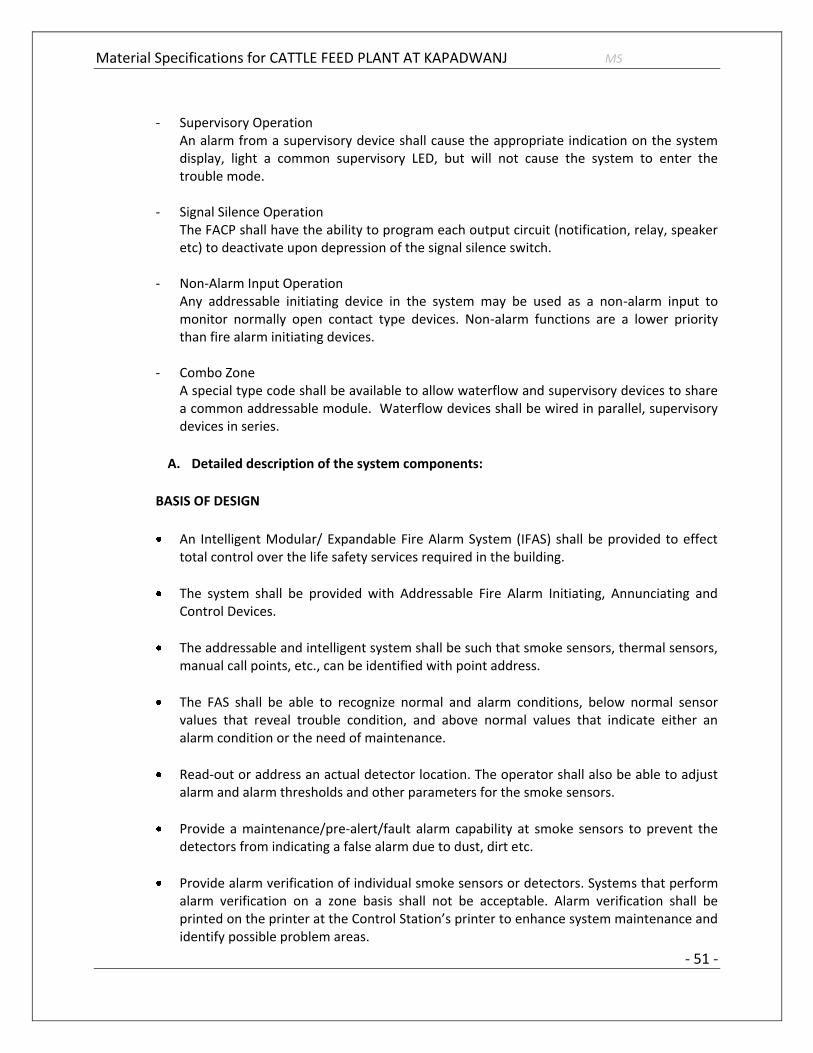
Material Specifications for CATTLE FEED PLANT AT KAPADWANJ MS
- 51 -
- Supervisory Operation
An alarm from a supervisory device shall cause the appropriate indication on the system display, light a common supervisory LED, but will not cause the system to enter the trouble mode.
- Signal Silence Operation The FACP shall have the ability to program each output circuit (notification, relay, speaker etc) to deactivate upon depression of the signal silence switch.
- Non-Alarm Input Operation Any addressable initiating device in the system may be used as a non-alarm input to monitor normally open contact type devices. Non-alarm functions are a lower priority than fire alarm initiating devices.
- Combo Zone
A special type code shall be available to allow waterflow and supervisory devices to share a common addressable module. Waterflow devices shall be wired in parallel, supervisory devices in series.
A. Detailed description of the system components:
BASIS OF DESIGN
An Intelligent Modular/ Expandable Fire Alarm System (IFAS) shall be provided to effect
total control over the life safety services required in the building.
The system shall be provided with Addressable Fire Alarm Initiating, Annunciating and Control Devices.
The addressable and intelligent system shall be such that smoke sensors, thermal sensors, manual call points, etc., can be identified with point address.
The FAS shall be able to recognize normal and alarm conditions, below normal sensor values that reveal trouble condition, and above normal values that indicate either an alarm condition or the need of maintenance.
Read-out or address an actual detector location. The operator shall also be able to adjust alarm and alarm thresholds and other parameters for the smoke sensors.
Provide a maintenance/pre-alert/fault alarm capability at smoke sensors to prevent the detectors from indicating a false alarm due to dust, dirt etc.
Provide alarm verification of individual smoke sensors or detectors. Systems that perform alarm verification on a zone basis shall not be acceptable. Alarm verification shall be printed on the printer at the Control Station’s printer to enhance system maintenance and identify possible problem areas.

Material Specifications for CATTLE FEED PLANT AT KAPADWANJ MS
- 52 -
Provide local numeric point address and LED display of device and current condition of the point.
Each detector shall use state-of-the-art Microprocessor Circuitry with error, detector self-diagnostics and supervision programs.
The detection of the fire shall be taken at the detector level.
Multi-Criteria Detectors shall be offered where by the system logic activation is based on any three inputs from the detector i.e. smoke, fixed heat or rate of rise heat.
Provide outputs that are addressable, i.e. outputs shall have point address. The operator shall be able to command such points manually or assign the points to Logical Point Groups (Software Zones) for pre-programmed operation.
In the event of a fire alarm, but not in a fault condition, the following action shall be performed automatically.
- The System Alarm LED on the main fire alarm control panel shall flash.
- A local sounder shall be sounded.
- The LCD display on the main fire alarm control panel shall indicate all information
associated with Fire Alarm condition including the type of alarm point and its location within the premises.
- Printing and history storage equipment shall log the information associated with the
Fire Alarm Control Panel condition, along with the time and date of occurrence.
- All system output programs assigned via control-by-event programs that are to be
activated by a particular point in alarm shall be executed, and the associated system outputs (alarm notification appliances and/or relays) shall be activated.
3.2 Addressable Intelligent Photoelectric Smoke Detector
The detectors shall use the photoelectric (light-scattering) principal to measure smoke density and shall, on command from the control panel, send data to the panel representing the analog level of smoke density.
3.3 Addressable Intelligent Multi-Sensor
FEATURES:
Automatically adjusts sensitivity levels without operator intervention or programming. Sensitivity increases with heat.

Material Specifications for CATTLE FEED PLANT AT KAPADWANJ MS
- 53 -
Microprocessor-based, combination photo and thermal technology.
Addressable-analog communication.
Sleek, low-profile design.
Two-wire Signaling Line Circuit connection.
Direct-Dial entry of address:
Addresses can be viewed and changed without electronic programmers.
Dual bi-color LED design provides 360° viewing angle.
LEDs lock red when in alarm. LEDs flash green in standby for normal condition.
Built-in tamper-resistant feature.
Sealed against back pressure.
Constructed of off-white Bayblend®, designed to commercial standards, and offers an attractive appearance.
SEMS screws for wiring of the separate base.
Several base options, including relay, isolator, and sounder.
Built-in functional test switch activated by external magnet.
Listed to UL 268.
Capable of heat-only alarm mode, enabled by a special command from the panel. Smoke alarms are ignored.
SPECIFICATIONS:
GENERAL SPECIFICATIONS:
Dimension: 2.0" (5.3 cm) high x 4.1" (10.4 cm) diameter installed in B501 base, 6.1" (15.5 cm) diameter installed in B710LP base.
Operating temperature: 0°C to 38°C (32°F to 100°F).
Operating altitude: up to 10,000 feet.

Material Specifications for CATTLE FEED PLANT AT KAPADWANJ MS
- 54 -
UL-Listed velocity range: 0 – 4000 ft./min. (1219.2 m/min.), suitable for installation in ducts.
Relative humidity: 10% – 93% non condensing.
Thermal sensing rating: fixed-temperature set point 135°F (57°C). ELECTRICAL SPECIFICATIONS:
Voltage range: 15 – 32 volts DC peak.
Standby current (max. avg.): 300 μA. Loop resistance: 50 ohms maximum; varies according to control panel used. Refer to panel installation manuals.
LED current (max.): 6.5 mA @ 24 VDC (“ON”).
STANDARDS:
UL Listed:S1115
ULC Listed: CS308
MEA Listed: 225-02-E
FM Approved
3.4 Response Indicators:
Remote Response Indicator shall be installed outside the areas normally kept closed to
identify the detectors response even if the room is locked. These indicators shall be able to indicate the status of the corresponding detectors in these areas.
3.5 Rate of Rise Detector (Hear detector):
Thermal detectors shall be intelligent addressable devices rated at 135 degrees Fahrenheit (58 degrees Celsius) and have a rate-of-rise element rated at 15 degrees F (9.4 degrees C) per minute. It shall connect via two wires to the fire alarm control panel signaling line circuit.

Material Specifications for CATTLE FEED PLANT AT KAPADWANJ MS
- 55 -
3.6 Addressable Control Module
Addressable control modules shall be provided to supervise and control the operation of one conventional NACs of compatible, 24 VDC powered, polarized audio/visual notification appliances.
The control module NAC may be wired for Style Z or Style Y (Class A/B) with up to 1 amp of inductive A/V signal, or 2 amps of resistive A/V signal operation.
Audio/visual power shall be provided by a separate supervised power circuit from the main fire alarm control panel or from a supervised UL listed remote power supply.
The control module shall be suitable for pilot duty applications and rated for a minimum of 0.6 amps at 30 VDC.
3.7 SOUNDER & STROBE CIRCUIT:
Features
• ADA/NFPA/UFC/ANSI compliant. • Meets OSHA 29 Part 1910.165. • Wall mount models are available with Field Selectable Candela.
• Settings of 15/30/75/110cd or 135/185cd (Multi-Candela models) or 1575cd (Single Candela model).
•Ceiling mount models are available with field selectable candela settings of 15/30/75/95cd or 115/177cd (multi-candela models).
• Strobes produce 1 flash per second over the regulated voltage range.
• 24 VDC with wide UL “Regulated Voltage” using filtered DC or unfiltered VRMS input voltage.
• Synchronize with Wheelock SM, DSM or power supply with built-in Wheelock sync protocol.
• Field selectable taps for 25 or 70 VRMS operation from 1/8 watt to 8 watts. • High efficiency design for maximum output at minimum wattage across a frequency range of 400 to 4000 HZ.
• Fast installation with IN/OUT screw terminals using #12 to #18 AWG wires.

Material Specifications for CATTLE FEED PLANT AT KAPADWANJ MS
- 56 -
Standard
• UL Listed: S2652 (Speakers); S2652/S5391 (Strobe/Speakers) • CSFM: 7125-0785:146; 7125-0785:152; 7320-0785:134 • MEA: 151-92-E V
3.8 Addressable Manual Fire Alarm Box (manual station)
Addressable manual fire alarm boxes shall, on command from the control panel, send data to the panel representing the state of the manual switch and the addressable communication module status. They shall use a key operated test-reset lock, and shall be designed so that after actual emergency operation, they cannot be restored to normal use except by the use of a key.
All operated stations shall have a positive, visual indication of operation and utilize a key type reset.
Manual fire alarm boxes shall be constructed of Lexan with clearly visible operating instructions provided on the cover. The word FIRE shall appear on the front of the stations in raised letters, 1.75 inches (44 mm) or larger.
3.9 Isolator Module
Isolator modules shall be provided to automatically isolate wire-to-wire short circuits on an SLC Class A or Class B branch. The isolator module shall limit the number of modules or detectors that may be rendered inoperative by a short circuit fault on the SLC loop segment or branch. At least one isolator module shall be provided for each floor or protected zone of the building.
If a wire-to-wire short occurs, the isolator module shall automatically open-circuit (disconnect) the SLC. When the short circuit condition is corrected, the isolator module shall automatically reconnect the isolated section.
The isolator module shall not require address-setting, and its operations shall be totally automatic. It shall not be necessary to replace or reset an isolator module after its normal operation.
The isolator module shall provide a single LED that shall flash to indicate that the isolator is operational and shall illuminate steadily to indicate that a short circuit condition has been detected and isolated.
3.10 Addressable Sounder Base:
The Addressable Sounder Base shall be compatible with the Fire detection and alarm
panel offered.

Material Specifications for CATTLE FEED PLANT AT KAPADWANJ MS
- 57 -
It shall be roof mounted or wall mounts type.
It shall be microprocessor based intelligent, addressable type.
It shall work at the same operating voltage of detectors.
It shall generate audio alarm on command from the fire detection and alarm panel.
It shall be able to carry out self diagnosis and automatic device mapping.
It shall be able to withstand ambient temperature upto 50 deg.C.
It should be able to generate at least 32 different types of tones.
Technical specifications
Operating voltage 15 V DC. . 33 V DC
Current consumption < 5 mA at maximum sound pressure level
Maximum sound pressure level is 100 dB(A) according to EN54-3
32 tones programmable from the fire detector control panel
Frequency range of 450 Hz to 2 900 Hz
Various signals for pre-alarm and alarm
Protection category according to DIN 60529: min IP 42
Operating temperature range min -25°C to +85°C
High resistance to electromagnetic effects. Approved for DIN EN 61000-4-4 Electrical fast transient/burst immunity test with 2 KV Delivery and installation ready for use
Installation
Installation shall be in accordance with the IS 2189, NEC, NFPA 72, local and state codes, and as recommended by the major equipment manufacturer.
All fire detection and alarm system devices, control panels and remote annunciators shall be flush mounted or surface mounted as per direction given by Engineer-in-Charge.
Manual fire alarm boxes shall be suitable for surface mounting or semi-flush mounting.

Material Specifications for CATTLE FEED PLANT AT KAPADWANJ MS
- 58 -
Commissioning Procedure shall be carried out in a methodical sequence as follows:
- Start-up,
- Configuration,
- Operability adjustment, Stable operation, Final adjustment
The Contractor shall finalize captured FDAS data to be recorded and the manner in which the data is to be taken.
Instruction
Instruction shall be provided as required for operating the system. Hands-on demonstrations of the operation of all system components and the entire system including program changes and functions shall be provided.
The contractor and/or the systems manufacturer's representatives shall provide a typewritten "Sequence of Operation”.
3.11 Monitor Modules:
Monitor modules supervise a circuit of dry-contact input devices, such as conventional heat detectors and pull stations, or monitor and power a circuit of two-wire smoke detectors.
Monitor Module is intended for use in intelligent, two-wire systems, where the individual address of each module is selected using the built-in rotary switches. It provides either a two-wire or four-wire fault-tolerant Initiating Device Circuit (IDC) for normally-open-contact fire alarm and supervisory devices. The module has a panel-controlled LED indicator.
SPECIFICATIONS:
Nominal operating voltage: 15 to 32 VDC.
Maximum current draw: 5.0 mA (LED on).
Average operating current: 350 μA (LED flashing), 1 communication
every 5 seconds, 47k EOL.
Maximum IDC wiring resistance: 40 ohms.
EOL resistance: 47K ohms.
Temperature range: 32°F to 120°F (0°C to 49°C).
Humidity range: 10% to 93% non condensing.

Material Specifications for CATTLE FEED PLANT AT KAPADWANJ MS
- 59 -
Dimensions: 4.5" (11.43 cm) high x 4" (10.16 cm) wide x 1.25" (3.175 cm) deep. Mounts to a 4" (10.16 cm) square x 2.125" (5.398 cm) deep box.
3.12 Relay module:
The Addressable Relay Module provides the system with a dry-contact output for activating a variety of auxiliary devices, such as fans, dampers, control equipment, etc. Addressability allows the dry contact to be activated, either manually or through panel programming, on a select basis.
Features:
Built-in type identification automatically identifies these devices to the control panel.
Internal circuitry and relay powered directly by two-wire fire alarm loop.
Integral LED “blinks” green each time a communication is received from the control panel and turns on in steady red when activated.
LED blink may be deselected globally (affects all devices).
High noise immunity (EMF/RFI).
Wide viewing angle of LED.
SEMS screws with clamping plates for wiring ease.
Direct-dial entry of address, and also for CLIP mode loops.
Applications:
The Relay module may be programmed to operate dry contacts for applications such as door holders or Air Handling Unit shutdown, and to reset four-wire smoke detector power.

Material Specifications for CATTLE FEED PLANT AT KAPADWANJ MS
- 60 -
4. VIDEO SURVEILLANCE / CCTV SYSTEM
4.1. GENERAL
The Surveillance System Components must be
IP based working on the same Network as the Data Network (LAN)
Must have mix of IP Cameras as specified in this document.
Must have the Video Analytics and monitoring software capable of matching the requirements mentioned in this document.
Must have the network based storage for the specified time and quality as specified.
Must be scalable in terms of equipments (no. of cameras) as well as features (Analytics).
All cameras shall have 3D noise reduction mechanism
The cameras shall be available with bi-directional audio feature and inbuilt SD/SDHC card slot.
All cameras shall be ONVIF compliant and be open to work in IPv4/IPv6.
(I) HD FIXED CS-MOUNT/BOX CAMERA SPECIFICATIONS GENERAL REQUIREMENTS:
The camera shall be a HD fixed-type CS-mount network camera supporting three codecs, JPEG,
MPEG-4 and H.264 high profile, any two of which can be used simultaneously. Camera shall utilize a 1/3” type CMOS/MOS/CCD sensor and having a resolution of 1280x960 and have a day/night capability.
The camera shall be ONVIF compliant.
Camera shall utilize JPEG, MPEG-4 and H.264 high profile compression. The cameras shall give high profile H.264 stream to minimize the bandwidth.
Network interface shall be via an 8-pin RJ-45 connector, 10Base-T /100Base-TX Ethernet.
The camera shall incorporate a built-in web server, such that the standard web browser Microsoft®
Internet Explorer (version 6.0, 7.0 or 8.0 recommended) can be used to access the camera without need for special viewer software.
The camera shall be capable of supporting up to 10 users simultaneously over the network.

Material Specifications for CATTLE FEED PLANT AT KAPADWANJ MS
- 61 -
The maximum frame rate capability of the camera over LAN shall be 30 frames per second at 1280 x 960 resolution in any of the three codecs (H.264 high profile/MPEG-4/JPEG).
The cameras shall have wide dynamic range and ability to show darker areas into clear images.
The camera shall incorporate a built-in motion detection capability.
The camera shall be capable of showing HD image only for a selected area to reduce
bandwidth and file storage requirements.
The camera shall support the following Network protocols: TCP/IP, DNS, RTP/RTCP, UDP, ARP, HTTP, ICMP, SMTP, FTP, DHCP, NTP and SNMP (MIB2). Network security shall be via Password (basic authentication) and IP filtering.
The camera shall have both FTP client and server capabilities.
The camera shall have user configurable port settings.
The camera shall be capable of dynamic IP address.
The camera shall have a CS-mount 2.9x (2.8 to 8.0 mm) F1.2 – F1.9 type vari-focal lens as a standard
accessory. The lens shall be a 1.3 MP D/N type from one of the approved makes or amaron/Fujinon.
The camera shall be Power over Ethernet capable, compliant to the 802.3af standard.
The camera shall have privacy zone masking which blocks out unwanted or prohibited area within
the video image to protect privacy. The camera shall be capable of masking up to two areas. Such capability shall be via vendor supplied utility software.
The camera shall have the capability for Camera ID as well as Date/Time data to be superimposed
on the video image.
The minimum electronic shutter setting shall be 1/30 second, and a maximum of 1/10,000 sec.
The camera shall have a 4-pin I/O interface located on the rear of the camera. There shall be an alarm input and output port.
The camera shall support IP Filtering, whereby access to the camera can be restricted to one or
more groups of selected users. Up to ten different groups can be established by defining an IP address range for each group.
The camera access shall be capable of Password Protection.
The administrator shall have complete access/control of the cameras.

Material Specifications for CATTLE FEED PLANT AT KAPADWANJ MS
- 62 -
Other levels of access can be set to limit user privileges to functions such as viewing, changing image
size, etc.
The camera shall have an internal image memory size of 8MB for alarm buffering.
The camera shall support multi-casting and unicast mode.
Camera shall have function to detect human faces and show clear images of the same.
The camera shall support IEEE-802.1X authentication, and shall:
- comply with the IEEE-802.1X standards.
- be capable of being integrated into an IEEE.802.1X network to achieve high network security,
CAMERA LENS SPECIFICATIONS
The camera shall have a CS-mount 2.9X compensated DC auto-iris type vari-focal lens as a standard
accessory.
Focal length shall be 2.8 – 8.0 mm with a field of view coverage of approx. 90˚ –35˚or better.
The aperture range for the lens shall be F1.2 to F1.9.
VIDEO-ELECTRICAL REQUIREMENTS
The camera input power shall be PoE (IEEE 802.3af compliant) and the power classification shall be Class 2.
The power connection shall be by means screw down mini terminal connectors for AC 24V and DC
12V operation.
The camera shall have composite analog video output in addition to streaming video via Ethernet.
The video output of the camera shall be selectable from either the NTSC or PAL standards.
The camera shall require a minimum scene illumination at 1280 x 960 of:
Color: 0.35 lx, 30IRE [IP], F1.4 or better B/W:

Material Specifications for CATTLE FEED PLANT AT KAPADWANJ MS
- 63 -
0.23 lx, 30IRE [IP], F1.4 or better Camera synchronization shall be Internal.
The camera shall have an ON/OFF selectable AGC, through the settings menu.
Camera shall have the following light compensation modes/features:
Standard: Can be used for various scenes. Scene 1: Brings out dark areas without losing details in the bright portions of the scene with high contrast. Scene 2: Light control mode : indoor / outdoor Scene 3: Brightens up dark areas of a scene.
The composite video output shall be 1.0 V peak to peak @ 75 ohms.
Power consumption for the camera shall be 5 watts maximum.
MECHANICAL REQUIREMENTS
The camera shall have a CS type camera lens mount.
The camera lens supplied with the camera shall be f2.8 to 8.0 mm F1.2 to F1.9, DC auto-iris type
vari-focal lens.
Input/output Alarm or sensor input and outputs, shall be via a 4-pin push type spring lock
connector.
The camera shall support one optically isolated Alarm or sensor input, and two relay outputs.
The camera shall provide Sensor in/Alarm out ports for interfacing with external equipment. Sensor
input shall be configurable for either Normally Open or Normally closed configuration.
Relay outputs shall be rated at 24V AC/24V DC, 1 Amp or less.
Top or bottom camera mounting shall be accomplished with a ¼” X 20 mounting screw hole, which
is available on both the top and bottom of the camera body.
Network interface shall be via RJ-45 located on the rear of the camera.

Material Specifications for CATTLE FEED PLANT AT KAPADWANJ MS
- 64 -
(II) High Definition (HD), Day/Night, Network PTZ Rapid Dome Camera
GENERAL REQUIREMENTS:
The camera shall be an HD Rapid Dome PTZ camera supporting three codecs, JPEG, MPEG-4 and
H.264 high profile, any two of which can be used simultaneously. The camera shall utilize a 1/4-type CMOS sensor of approx 1.3 Megapixel and have a True day/night capability.
The camera shall be capable of 360 degree pan rotation and a tilt range of 210 degrees, designed for ceiling mount operation.
The camera shall incorporate a built-in 36X optical, auto-focus zoom lens, and shall have 12X digital
zoom capability.
The camera shall be capable of an e-flip function, a feature when the camera passes the down
position, electronically flips the image180 degrees.
The camera shall be capable of guard tour (position tour), for which up to sixteen (16) presets can
be programmed, and moves to each preset sequentially when guard tour is activated. Up to five programs (tours) can be set.
The camera shall be capable of shadow tour, which is used to learn an operator's PTZ control actions
(including those made with a joystick) and then repeats the motions on command. Up to four shadow tours can be set.
The camera shall have a noise reduction capability which reduces AGC noise to provide clear images without motion blur. This design feature also reduces image data size.
The network interface shall be via an 8-pin RJ-45 connector, 10Base-T/100Base-TX Ethernet. Both
IPv6 and IPv4 are supported.
The camera shall utilize JPEG, MPEG-4 and H.264 high profile compression. The minimum resolution
for H.264 high profile shall be 1280x960 or better at 30 fps.
The camera shall have the capability of simultaneously encoding up to two of the following codecs in
any combination: JPEG, MPEG-4, and/or H.264 high profile including multiple instances of the same codec.
The supported operating systems shall be Microsoft Windows 7™ 32bit (Ultimate/Professional), Windows Vista® 32bit (Ultimate/Business), Windows® XP 32bit (Professional). Minimum PC requirements shall be the Intel Core®2 Duo Processor, 2 GHz or higher, with 1GB RAM or more supporting 1600 x 1200 resolution and 24-bit True Color display capability with Ethernet 100Base-TX.

Material Specifications for CATTLE FEED PLANT AT KAPADWANJ MS
- 65 -
The camera shall incorporate a built-in web server, such that the standard web browser Microsoft® Internet Explorer (version 6.0, 7.0 or 8.0 recommended) can be used to access the camera without need for special viewer software.
The camera shall be capable of generating HTML code for the video image, allowing for easy web
page integration.
The camera shall be capable of supporting up to ten (10) users simultaneously over the network.
The camera shall have up to six user level settings.
The administrator shall have complete access/control of the cameras. The other five levels of access can be set to limit user privileges to functions such as viewing, changing image size, etc.
The camera shall have the capability to stream JPEG, MPEG-4 and H.264 high profile video in TCP
protocol or MPEG-4 and H.264 in UDP (unicast/multicast) protocol.
The camera shall incorporate a built-in algorithm for intelligent motion detection capability.
The camera shall support the following network protocols: TCP, IPv4, IPv6, DNS, RTP/RTCP, RTSP,
UDP, ARP, HTTP, HTTPS, ICMP, IGMPv3, SMTP, FTPs, FTPc, DHCP, NTP and SNMP (MIB-2). Network security shall be via Password (basic authentication) and IP filtering.
The camera shall support HTTPS client authentication.
The camera shall support 802.1X.
The camera shall be compliant with the industry standard ONVIF (Open Network Video Interface
Forum) specification.
The camera shall have user configurable port settings.
The camera shall be capable of dynamic IP address change. notification. It shall accomplish this via
an email to a specified address or by HTTP when its IP address changes.
The camera shall have an email (SMTP) notification capability which allows the following:
Sending an email to pre-specified users when an alarm is triggered by either motion detection, video motion filters, camera tampering detection, audio detection or sensor input. A JPEG image, which is linked with the alarm trigger, can be attached to the email.
Periodically capturing a JPEG image and sending it via email.
Sending an email alert to pre-specified users when video loss occurs and/or a built-in fan malfunctions.

Material Specifications for CATTLE FEED PLANT AT KAPADWANJ MS
- 66 -
The camera shall have privacy zone masking which blocks out unwanted or prohibited area within the video image to protect privacy.
The camera software should include the IP Setup (including group camera management) program,
Firmware Upgrade Tool, Panorama Creator, Privacy Masking Tool, Custom Homepage Installer, and Group Camera Setting Scheduler. The software shall be supplied with the camera as a standard accessory.
The minimum electronic shutter setting shall be 1/30 second, and a maximum of 1/10,000 sec.
The camera shall have one input sensor and one output port.
The camera shall support IP Filtering, whereby access to the camera can be restricted to one or
more groups of selected users. Up to ten (10) different groups can be established by defining an IP address range for each group.
The camera shall be capable of limiting the bandwidth from 64 kbps to 8 Mbps in MPEG-4 or H.264,
and from 0.5 Mbps to an unlimited bandwidth in JPEG.
The camera shall have an internal image memory size of approx. 8 MB for buffering JPEG/MPEG-4/H.264 images and audio.
The camera shall also have an edge-storage function that helps to record in case of alarm/network failure.
The camera shall support IEEE-802.1X authentication, and shall:
comply with the IEEE-802.1X standards,
be capable of being integrated into an IEEE-802.1X network to achieve high network security,
support EAP-TLS mode to use a key pair from a Certificate Authority (CA),
support EAP-MD5 mode,
Support PEAP mode.
CAMERA LENS SPECIFICATIONS:
The camera shall have an integrated 36X auto-focus zoom lens.
Focal length shall be 3.3 to 119 mm with field of view coverage of 60° to 46° typical.
The aperture range for the lens shall be F1.4 to F22.
VIDEO-ELECTRICAL REQUIREMENTS:
The camera input power shall be a power voltage of AC 24V.

Material Specifications for CATTLE FEED PLANT AT KAPADWANJ MS
- 67 -
Camera synchronization shall be Internal.
Power consumption for the camera shall be 30 watts maximum.
AUDIO REQUIREMENTS:
The camera shall support bi-directional audio, using G.711 (64kbps) and G.726 (40, 32, 24, 16 kbps) codecs.
The camera shall have mini-jack connectors accessible via pigtail to support external microphone and active speakers. Mic/line input shall be switchable. Mic input shall be monaural, 2.2 kilo ohms, 2.5V DC plug-in-power, line input shall be monaural, and active speaker output shall have a maximum output level of 1 Vrms.
The camera shall be capable of storing up to three audio files. Audio files shall be generated and transferred to the camera using either the web browser or the manufacturer provided audio upload software tool.
The camera shall support the voice alert function, which can automatically play an audio file stored
on the camera by an alarm trigger using motion detection, advanced video motion filters, camera tampering detection, audio detection or via a sensor input.
The camera shall have the following audio enhancement capabilities: Dynamic Range Compressor
which automatically controls microphone gain to optimize audio volume level, Echo Canceller, and Ambient Sound Filter to suppress constant ambient noise.
The camera shall provide time stamp on the streaming audio. Time stamp shall be inserted in the header area of the audio data.
Audio data shall be interleaved with video and serially transmitted in a single session for synchronization.
User shall have the capability to activate the microphone input via the web interface.
MECHANICAL REQUIREMENTS:
The camera shall have 360° endless pan rotation and 200° tilt range.
The camera shall have a pan/tilt speed range of between 0.1° per second and 100° per second. The
camera shall have two hundred and fifty six (256) user defined presets, with a repeatable mechanical preset accuracy of ±0.045° (typical).
The camera shall be IP66 rated and IK10 or equivalent rated in accordance with the relevant
standards such as IEC 60529 and IEC 62262.

Material Specifications for CATTLE FEED PLANT AT KAPADWANJ MS
- 68 -
4.2. 6-PORT INDUSTRIAL PoE-SWITCH WITH 2-PORT POPULATED MINI GBIC SFP PORTS:
A. Switch Properties:
1. MAC table size: 1K
2. Packet buffer size: 512 kb
3. Processing Type: Store and Forward
B. Interface:
1. Fiber Ports: 100BaseFX ports (SC/ST connector)
2. RJ45 Ports: 10/100BaseT(X) auto negotiation speed, Full/Half duplex mode, and auto MDI/MDI-X connection
3. PoE Pin out: V, V, V+, V+ for pin 1, 2, 3, 6
(Endspan, MDI-X Alternative A)
4. LED Indicators: PWR1, PWR2, 10/100M, PoE
5. Alarm Contact: 2 relay outputs with current carrying
capacity of 1 A @ 24 VDC
C. Power Requirements:
1. Input Voltage: 24/48 VDC (20 to 60 VDC), redundant inputs
2. Input Current: Max 7.5 A @ 24 VDC
(supports up to 4 ports at 30W per PoE port)
3. Overload Current Protection: Present
4. Connection: 1 removable 4-contact terminal blocks
5. Reverse Polarity Protection: Present

Material Specifications for CATTLE FEED PLANT AT KAPADWANJ MS
- 69 -
D. Physical Characteristics:
1. Housing: Metal, IP30 protection 2. Dimensions: 50.3 x 115 x 70 mm
(1.98 x 4.53 x 2.76 in) 3. Weight: 375 g 4. Installation: DIN-Rail mounting, wall mounting
(with optional kit)
E. Standards:
1. IEEE 802.3af/at for Power-over-Ethernet 2. IEEE 802.3 for 10BaseT 3. IEEE 802.3u for 100BaseT(X) 4. IEEE 802.3x for Flow Control
F. Standards & Certifications:
1. UL 508 2. UL 60950-1 3. CSA C22.2 No. 60950-1 4. EN 60950-1
G. Environmental Limits:
1. Operating temperature: 0 to 60°C (32 to 140°F) -40 to 75°C (-40 to 167°F)
2. Storage Temperature: -40 to 85°C (-40 to 185°F) 3. Ambient Relative Humidity 5 to 95% (non-condensing)
4.3. VIDEO MANAGEMENT SOFTWARE (VMS)
It shall support a seamless unification of IP video management system (VMS), IP access control
system (ACS) & Third Party Systems under a single platform.
The Unified Security Platform user interface applications should present a unified security
interface for the management, configuration, monitoring, and reporting of embedded VMS, ACS and associated edge devices.
The Unified Platform must support multiple brands of edge devices for surveillance & access control.
In order to create an openness of the system the Security Platform provider shall be different than the camera make.

Material Specifications for CATTLE FEED PLANT AT KAPADWANJ MS
- 70 -
The Platform shall support SDK (Software Development Kit) integration for integrating third party systems such as and more.
The VMS shall support ONVIF – industry standard for the interface of IP-based physical security products.
The VMS Module shall allow the Direct configuration of IP camera device with no requirement to directly connect via web page of IP camera or encoder to configure parameters such as : Discover on IP network and set IP Address, Frame Rate, Resolution, Motion detection : with in camera or server based, Bit Rate, Key frame interval, Digital I/O, Audio Inputs/Outputs, EDGE Storage, Ability to update firmware of IP camera or encoder. Any configuration changes do not require these services to be restarted.
Unified Security Platform shall be compatible with both 32-bit and 64-bit operating systems including Windows Vista, Windows XP, Windows 7, Windows Server 2003 and Windows Server 2008.
The VMS shall be based on a true open architecture that shall allow for use of non- proprietary
workstation and server hardware, non-proprietary network infrastructure and non-proprietary storage.
The VMS shall offer a complete and scalable video surveillance solution which allows cameras
to be added on a unit-by-unit basis.
All video streams supplied from analog cameras or IP cameras shall be digitally encoded in
H.264 or better compression formats and recorded simultaneously in real time.
The VMS shall support configuration of individually configurable multiple streams for Live & Recording. This functionality shall also support configuration of the each camera stream separately. Altering the setting of one camera shall not affect the recording & display settings of other cameras.
The VMS shall be able to use multiple CCTV keyboards to operate the entire set of cameras throughout the system, including cameras of various manufacturers’ brands, including their PTZ functionalities.
The VMS shall be able to retrieve and set the current position of PTZ cameras using XYZ coordinates.
The Platform shall consist of a role-based architecture, with each Server hosting one or more roles.
The System shall be managed by the central database role that contains all the system information and component configuration.

Material Specifications for CATTLE FEED PLANT AT KAPADWANJ MS
- 71 -
The Database Management Role shall authenticate users and give access to the system based on predefined user access rights or privileges, and security partition settings.
The Database Management Role shall support the configuration of camera units, access control
units, PTZ functionalities. Camera sequences, recording schedules.
The Video Recording Role shall be responsible for managing cameras and encoders under its
control and archiving video.
The system shall have a routing role responsible for routing video and audio streams across the networks from the source to destination.
The system shall have Health Monitoring Role for monitoring and logging health events and warnings from the various client applications, roles, and services that are part of the Security Platform The role shall also log events within the Windows Event Log, generating reports on health statistics and health history.
The Surveillance User Interface shall able to use for monitoring of video from the cameras,
transactions from access control and the events & alarms. The Interface shall also facilitate the recorded video.
The user interface shall provide control & monitor of IP network.
User Interface shall facilitate the control of Pan Tilt & Zoom functionality and presets of the PTZ cameras.
User Interface shall also facilitate the control of iris and focus of the camera.
User Interface shall possible to perform digital zooming on the live as well as playback video.
User Interface shall allow administrators and operators with appropriate privileges to monitor the unified security platform, run reports, and manage alarms.
The User Interface shall support following to enhance usability and operator efficiency such as
o Dynamically adaptive interface that adjusts in real-time to what the operator is doing. o A dynamic dashboard loaded with entity-specific widgets, e.g. door and camera widget. o Use of transparent overlays that can display multiple data in a seamless fashion. o Display tile menus and quick commands. o Consolidated and consistent workflows. o Tile menus and quick commands easily accessible within every display tile of the user
workspace.
The User Interface shall have task based approach for monitoring of video, access control &
alarm monitoring.
User Interface shall have task for investigation of video bookmark, smart motion search, archive

Material Specifications for CATTLE FEED PLANT AT KAPADWANJ MS
- 72 -
reports, audit trails and activity reporting.
User Interface shall support a sequence of operations and operator or administrator shall execute to complete an activity. The “flow” relates to a clearly defined timeline or sequence for executing the activity.
The user shall have full control over the user workspace through a variety of user- selectable customization options. Administrators shall also be able to limit what users and operators can modify in their work space through privileges.
Once customized, the user shall be able to save his workspace.
The user workspace shall be accessible by a specific user from any client application on the network.
Display tile patterns shall be customizable.
Event or alarm lists shall span anywhere from a portion of the screen upto the entire screen, and shall be resizable by the user. The length of event or alarm lists shall be user-defined. Scroll bars shall enable the user to navigate through lengthy lists of events and alarms.
The User Interface shall support multiple display tile patterns,e.g.1 display tile(1x1 matrix),16tiles(8x8matrix),and multiple additional variations.
The User Interface shall support as many monitors as the PC video adapters and Windows Operating System are capable of accepting.
The User Interface shall display of all cameras attached to the system.
Shall support live video monitoring on each and every display tile within a task in the user's
workspace.
The operator shall be able to drag and drop a camera into a display tile for live viewing.
The operator shall be able to drag and drop a camera from a display tile for live viewing.
The User Interface shall allow operators to bookmark important events for later retrieval on any archiving camera. Operators can uniquely name each bookmark in order to facilitate future searches.
The operator shall be able to start/stop recording on any camera in the system, which is configured to allow manual recording, by clicking on a single button.
The operator shall able to switch one or more video tile to switch for instant replay. This operation shall not affect live monitoring of other cameras.

Material Specifications for CATTLE FEED PLANT AT KAPADWANJ MS
- 73 -
Users shall be able to take snapshots of live video and be able to save or print the snapshots.
The user shall be able to view the same camera multiple times in different tiles.
The Server Monitoring Service shall be installed on all PCs/servers running with security platform software. In the event of a malfunction or failure, the Server Monitoring Service shall restart the failed service. As a last resort, the Server Monitoring Service shall reboot the server/PC if it is unable to restart the service.
The Platform shall support the Alarm Management functionality. The User shall have the ability
to acknowledge alarms, create an incident upon alarm acknowledgement, and put an alarm to
snooze. The user shall able to spontaneously trigger alarms based on something he or she sees in the system.
The Surveillance User interface's video playback capabilities shall include:
Shall support audio and video play back of any time span.
Shall support video play back on each and every display tile.
Shall allow operators to switch to instant replay of the video for any archiving camera with the simple click of button.
Shall allow the operator to select between instant synch of all video streams in play back mode allowing operators to view events from multiple angles or across several camera fields, or non-synchronous playback.
Shall allow the operator to simultaneously view the same camera in multiple tiles at different time intervals.
Shall allow the operator to control the play back with: o Pause o Lock Speed o Forward and Reverse Playback at:1x,2x,4x,6x,8x,10x,20x,40x,100x. o Forward and Reverse Play back frame by frame o Slow Forward and Reverse Playback at:1/8x,1/4x,1/3x,1/2x. o Loop play back between two time markers
Shall display a single timeline, or optionally one timeline for each selected video stream, with which the operator can navigate through the video sequence by simply clicking on any point in the timeline.
Shall display the level of motion at any point on a timeline.
Shall clearly display book marks events on the timeline(s).
Shall be able to query archived video using various search criteria, including but not limited to, time, date, camera, and area, among others.
Shall provide the tool to search video and associated audio on user-defined events or motion parameters.
Shall allow operators to define an area of the video field in which to search for motion as well as define the amount of motion that shall trigger search results. The Surveillance User Interface shall then retrieve all archived video streams which contain motion which meets the search parameters. There shall be a graphical timeline where the time of each search hit shall be indicated.

Material Specifications for CATTLE FEED PLANT AT KAPADWANJ MS
- 74 -
Shall allow operators to browse through a list of all bookmarks created on the system and select any book marked event for viewing.
Shall allow the user to add bookmarks to previously archived video for easier searching and retrieval.
Shall support digital zoom on play back video streams.
Shall provide still image export to PNG, JPEG, GIF, and BMP format with Date and Time stamp and Camera Name on the image (snapshot).
Shall provide tools to export video on various media such as a CD-ROM.
Shall allow operators to load previously exported video files from their computer or network.
Shall allow queries to be saved upon closing the Archive Player Application and reappear when the application is reopened.
The Security Platform shall permit the user to select multiple entities to monitor from the Surveillance User Interface by adding the entities one by one to the tracking list.
The Surveillance User Interface shall provide the option to filter which events shall be displayed
in the display tile layout and/or event list layout.
It shall also possible to lock the display tiles for the activity of a specific entity.
The user shall be permitted to start or pause the viewing of events within each display tile.
The User Interface shall support the ability to manually track a moving target with the single
click of a button.
The ability to switch from one camera view to an adjacent camera shall be done within a single
display tile.
Switching between camera streams shall be accomplished by simply clicking on the transparent
overlay.
Visual tracking shall be available with both live and recorded video.
The user interface monitoring client shall able to take control of other client station based on the privilege level and control the tile of the other client like a video wall application.
4.4. Configuration User Interface
The Configuration User Interface shall allow the administrator or users with appropriate privileges to change video configuration. It shall provide the ability to change video quality, bandwidth and frame rate parameters on a per camera (stream) basis for both live and recorded video.

Material Specifications for CATTLE FEED PLANT AT KAPADWANJ MS
- 75 -
It shall provide the ability to configure brightness, contrast and hue settings for each camera on the same.
The Configuration user interface shall provide the capability to enable & change audio parameters, audio recording serial port configuration, I/O con figuration on camera device units.
The Configuration User Interface shall provide the ability to set recording schedules and modes for each individual camera. The recording mode shall be:
o Continuous o On motion and Manual o Manual only o Disabled
The Configuration User Interface shall support the creation of schedules to which any of the
following functional aspects can be attached:
Video quality(for each video stream per camera)
Recording(for each camera)
Motion detection(for each detection zone per camera)
Brightness, Contrast, Hue(for each camera)
Camera sequence execution
The configuration User Interface shall support creation of unlimited recording schedules and
assign any camera to any schedules.
The Configuration User Interface shall provide the capability to set a pan-tilt-zoom protocol
to a specific Camera device serial port and allow mixing domes of various manufacturers within a system.

Material Specifications for CATTLE FEED PLANT AT KAPADWANJ MS
- 76 -
4.5. Archiving
The Archiver (Recording role) shall use an event and time stamp database for advanced search
of audio/video archives. This database shall be Microsoft SQL 2008 or SQL 2012
The Archiver shall digitally sign recorded video using 248-bitRSA public/private key cryptography.
The Archiver shall offer a plug and play type hardware discovery service with the following functionalities:
The Archiver shall have the capacity to configure the key frame interval(I-frame)in seconds or number of frames.
The Archiver shall support configuration of pre-alarm and post-alarm recording option that can be set between one second and 5 minutes on a per camera basis.
The Archiver shall support minimum 300 cameras or 300 Mbps of recording throughput whichever comes first in case the network is end to end multicast.
The Archiver shall support “unit level motion detection” as well as “software level motion detection”.
Software level motion detection shall able to divide camera field of view in 6 detection zone for setting up individual motion setting in each zone and trigger an event for each zone separately.
The Archiver shall have the capacity to communicate with Camera device using 128bits SSL encryption.
The Archiver shall have the capacity to communicate with camera device using HTTPS secure protocol.
The Archiver shall have the capacity to receive multicast UDP streams directly from the camera unit.
For network topologies that restrict the camera device from sending multicast UDP streams, the Archiver shall redirect audio/video streams to active viewing clients on the network using multicast UDP.
The Archiver shall have the capacity to redirect audio/video stream to active viewing clients on the network using unicast UDP or TCP.
The user interface of the monitoring station shall support dynamically switch the Live stream from – High Resolution, Low Resolution & Live (normal). This switching shall happen based on the resolution of monitoring tile & closest stream configuration.
The Archiver shall offer to set retention period for archive video for preset number of days. It shall also delete oldest video data if the disk is full before the retention time occurs.
The Archiver shall allow important video sequences to be protected against normal disk cleanup routines.
The Archiver shall keep a log and compile statistics on disk space usage.
The Archiver shall have the capacity to down-sample video streams for storage saving purposes.
The Archiver shall support camera unit with edge recording capabilities and offer the following capacity:
o The ability to playback at different speeds the video recorded on the Camera device. o The ability to offload the video on schedule, on event or manually the video recorded
on the camera device to store it on the Archiver. o It shall be possible to filter the video that is being off loaded using one or multiple of
the following filters:
B Time interval

Material Specifications for CATTLE FEED PLANT AT KAPADWANJ MS
- 77 -
B Play back request B Video analytic events B Motion events B Bookmarks B Alarms
The Archiver shall support analytics events received from camera unit having capability of edge analytics.
4.6. Failover and Standby Functionality
The Unified Security Platform shall support native and off-the-shelf failover options.
The Standby Directory Role shall take over the responsibility of system management in case the primary Directory fails. The fail over shall occur in less than 1 minute. No action from the user shall be required.
This functionality shall even be able to achieve without using the windows clustering.
The Standby Archiver shall act as replacement of Archiver role on hot standby in case the
primary Archiver role is unavailable. Failover shall occur in less than 1 minute. No action from the user shall be required.
Failover Archiver shall take over for – server failure, storage failure, manually shift the Archiver Role to standby Archiver to perform maintenance activity on primary server.
It shall be possible for a single Standby Archiver Server to act as the Standby for one or multiple Archiver roles.
It shall be possible for any Archiver role in the system to be designated as another's stand by and vice-versa.
The Standby Archiver shall have the ability to act as a Redundant Archiver and maintain an exact copy of everything recorded by the default Archiver, i.e., audio/video archives, events and bookmarks.
Redundancy shall be configured on a camera by camera basis.
The Redundant Archiver shall use a multicast video stream from the Camera unit and shall not require an additional connection to any Camera device.
4.7. Unified WebClient
The UPS shall support a unified web client for video &access control.
The Web client shall be a thin client with no download required other than an internet web

Material Specifications for CATTLE FEED PLANT AT KAPADWANJ MS
- 78 -
browser or standard web browser plug ins.
The Web Client shall be platform independent and run within Microsoft Internet Explorer,
Firefox, Safari, and Google Chrome.
4.8. Smart phone and Tablet Apps
The Security Platform shall support mobile apps for various off-the-shelf smart phones and
tablets. Including Apple iPod Touch, iPhone, and iPad, RIM BlackBerry smart-phones, Android-compatible smart-phones and tablets.
It shall support monitoring of live camera. Receive alarm push notifications save snapshot
locally on device, control PTZ.
4.9. VIDEO SURVEILLANCE STORAGE
Configuration & Specification for Storage System for Video Surveillance & Recordings on a 24 Hrs x 15Days Basis
The Storage should support the following functionalities:
- The storage system should offer integrated data protection through RAID technology (RAID 0, 1, 10, 5, 5+1(hot spare), and 6 protection on a per-Storage Pool basis) and multiple RAID types in an array. The storage should provide simultaneous NAS file level and iSCSI block level access.
- It should Support both file and block storage pools.
- Block storage pools; 32 LUNS maximum per pool. 128 LUNs maximum per device.
- File storage pools; 256 LUNs Maximum per pool. 256 LUNs maximum per device.
- Windows Active Directory Trusted Domains, Microsoft Cluster Server and Hyper-V Live
Migration support
- The storage should be certified for VMware vSphere™ 5.0, iSCSI ,Windows® Server 2003 and Windows Server 2008, and 2008 R2 including Microsoft® Cluster Server and Hyper-V Live Migration. XenServer™, 5.6 (w/ MPIO), iSCSI & NFS.
- The storage should possess Native Security Support with robust username and password authorized access. Should create additional users and secure their content with password protection.
- Encrypted Volume: Should create an encrypted volume with an assigned password for securing
the data on the encrypted volume.

Material Specifications for CATTLE FEED PLANT AT KAPADWANJ MS
- 79 -
- User Quotas: Should manage capacity by setting maximum limits per user.
- The storage of 16 TB should be built in and should be expandable to maximum of 36TB in a single array without I/O interruption.
- It should have inbuilt device to device asynchronous replication to ensure data integrity at both the source and replication target.
- It should provide high throughput by NIC bonding for failover and load balancing including 802.3ad link aggregation.
- Jumbo frame support for 4000 and 9000 byte payloads.
- VLAN Tagging capability to IEEE 802.1Q standard.
- iSCSI persistent reservations for clustered Microsoft environment and support for SCSI-3 persistent reservations.
- The storage should possess the following Power Savings features: Scheduled Power: Automatically power on or turn off storage at a pre-selected time schedule
Wake-On-LAN: Powers on storage device when a “magic-packet” wake-up signal is sent over the network Uninterruptible Power Supply (UPS) Support: Enables unattended system shutdown via the USB port without data loss in the case of power failure.
- The device should support CIFS/SMB/Rally (Microsoft), NFS (Linux/UNIX), AFP/Bonjour (Apple),
FTP, SFTP, TFTP, HTTP, HTTPS, WebDAV, Windows DFS, SNMP.
- It should have redundant hot-swappable power supply (1+1)
- It should have a Simple Management using the web User Interface – either local or remote.
- Configuration Backup and Restore: should allow to back up and restore system configuration information. Backing up a configuration saves various system properties, including users, groups, device identification, and Share names and permissions.
- System Status: should provide consolidated resource on space utilization, device information, and status
- SMART Hard Drive Monitor: Should continuously monitor and report on the health of all drives in the storage system

Material Specifications for CATTLE FEED PLANT AT KAPADWANJ MS
- 80 -
- Reporting: Should have Email alerts and Event Logging provide up-to-the-minute updates on the status of the device.
- Web-based computing architecture that connects storage Array devices to other individuals and/or devices via the Internet
4.10. Hardware specifications
- Rack mountable and 2U form factor - Minimum 8GB DDR2 RAM - Minimum 12 slots for 3.5 inch 7200RPM Server Class SATA hard disk drives - Intel core2 duo processor - Minimum three USB ports - Minimum four Gigabit Ethernet ports - Drive type – 7200RPM Server Class SATA hard disk drives and should support 1TB, 2TB & 3TB
drives & Solid state drive support
4.11. SERVERS and CLIENTS FOR VIDEO SURVEILLANCE SYSTEM
Server Hardware - Industry standard Intel based platform, rack mountable, redundancy architecture for critical hardware components, licensed Micrsoft Server Operating system and requisite user licenses, licensed application suites.2x Dual Core Intel® Xeon® 5150, 2.66 GHz, 4 MB Cache, 1333 MHz FSB, 8 GB of RAM, 80 GB of storage or more, Additional hard drive(s) for video storage, Standard SVGA video card, 800 x 600 or higher screen resolution, 10/100/1000 Ethernet Network Interface Card, DVD ROM Drive.
Client Hardware - Industry standard Intel based platform, rack mountable, redundancy architecture for critical hardware components, licensed Microsoft Operating system and requisite user licenses, licensed application suites. Intel Core i7 2600 @ 3.4 GHz, 8 GB of RAM DDR3 ,80 GB SATA II hard drive for OS and VMS applications, NVidia GTX 570 or DirectX VA 2.0 compatible card with 1 GB of RAM , 1600 x 1200 or higher screen resolution , 100/1000 Ethernet Network Interface Card ,16x DVD+/- RW Drive.
Recommended Operating Systems:
- Workstation:» Microsoft® Windows XP Pro SP2/SP3 32-bit/64-bit » Microsoft® Windows
Vista SP1 Business or Ultimate 32-bit/64-bit» Microsoft® Windows 7 Professional or Ultimate 32-bit/64-bit
- Server:» Microsoft® Windows Server® 2008 Standard Edition 64-bit » Microsoft® Windows Server® 2008 Enterprise Edition 64-bit
Browser Requirements» Internet Explorer 6, 7 or 8 (for Web Clients)

Material Specifications for CATTLE FEED PLANT AT KAPADWANJ MS
- 81 -
5. ACCESS CONTROL SYSTEM
5.1 DESCRIPTION
The Access Control System automates the process of tracking employees and visitors as they check in and out for work and provide accurate time and leave data for each employee. This helps to increase efficiency and productivity of the organization. Access control secures valuable assets of the organization that depends on having right answers to who, what, where and when. Defining, controlling monitoring entries and exits in each area is necessary for putting right people in right time. 5.2 FEATURES
Access Control
2-Person Rule Degraded Operation
Do Not Disturb (DND)
First-in User Rule
Occupancy Control
Who’s In
Access Mode
Card Only Finger Only Card + Finger Card + PIN
Finger + PIN Card + Finger + PIN
Card or Finger or PIN
Verification 1:1 or 1: N
Bypass Finger Zone-wise
Access Policies
Home Zone Visit Zone Access Levels Physical Zones
Short Duration Time Zones User Groups VIP Access
Admin
Audit Trail Import Master Data
Backup and Restore
Default Configurations
Firmware Upgrade
Restrict Work-Stations
Facility Code
Alarm
Audit Trail Import Master Data
Backup and Restore
Default Configurations
Firmware Upgrade
Restrict Work-Stations
Facility Code
Anti-Pass Back
Forgiveness Hard/Soft Local/Global
Architecture
Centralized Management
Distributed Processing
Web-based Interface
Attendance
Absenteeism Policies
Compensatory Off (Comp-OFF)
Date-wise Policies
Detail and Summary

Material Specifications for CATTLE FEED PLANT AT KAPADWANJ MS
- 82 -
Policies
Early-Out Policies
Global Parameters
Late-In Policies Manual Entries and Corrections
Multiple Organizations
Overtime Policies
Past Adjustments
Real Time Processing
Selectable Periods
Authorization
Attendance Compensatory Off (Comp-OFF)
Early-Out Correction
Hierarchy
Late-In Correction
Overtime
Blocked Users
Absentee Unauthorized Attempts
Usage Count
Cafeteria Management*
Card, Finger and PIN Support
Credit/Debit Limit
Define Menu Display Items with Rates
Print Order Slip Reports Select Item and Order
Time-based Menu
Validate User
Date-Time
Clock Synchronization
Country-Specific Format
Daylight Saving Time
Door Controller
Auxiliary Input Port (Supervised)
Auxiliary Output Port
Buzzer and LEDs Touch Sense Keys
Dot-Matrix LCD Duress Detection and Reporting
Ethernet and RS485
External Reader Support
NVR/DVR Integration
Programmable Entry/Exit
Request to Exit (REX) Switch
Tamper Detection
User Name and ID Display
Door Auto Relock
Man-Trap (Door Interlock)
Employee Self Service
Attendance Approvals
Leave Approvals Leave Requests Plan Shift Schedules

Material Specifications for CATTLE FEED PLANT AT KAPADWANJ MS
- 83 -
Reporting Hierarchy
View Attendance Details
View Cafeteria Details
View Leave Details
View Shift Schedules
Visitor Pre-registration
Enroll
Card Finger From Door Controller (Menu or Special Cards)
From Enrollment Station
Upload Photo (from Station)
Export
Access Control Events
Attendance Events
Attendance Summary
Cafeteria Events
Excel, Word, XML, CSV, PDF
Programmable Fields
Holidays
Multiple Schedules
Restricted
Input-Output Ports
Control Linking Status
Leave Management
Types Creation Accounting Periods
Accumulation Rules
Balance, Carry Forward/Lapse
Opening, Credit, Debit
Encashmen Organization-wise Groups
Requests and Approvals
Login Policies
Login Policies
Disable Passive Users
Forced Password Change
Multiple Levels and Rights
Strong Password
Monitor and Control
Alarms Dead-Man Zone Door Controllers Events
Guard Tours Input-Output Links
Local Panel Controllers
Override Access Policies
Ports Status Remote
Panel Controller

Material Specifications for CATTLE FEED PLANT AT KAPADWANJ MS
- 84 -
Alarm Input Port (Fire Alarm)
Auxiliary Output Port
Battery-Backup and Charger
USB Port
Report Formats
Text and Graphical
Excel, Word, XML, CSV, RTP, PDF
Shift Schedule
Automatic Corrections
Multiple Shifts and Schedules
Plan and View
Smart Card
Cafeteria Usage Organization Security Code
User Profile User Templates
Special Functions
User Groups Cards Menu
User
Creation and Management
Delete Enroll Synchronize
User Alerts
Email Message Board Notice Board SMS
Visitor Management
Visitor Management
Blocked Visitors Documents Scan Escort Frequent Visitors
Identification Pass Creation Pre-Registration SMS and Email Notification

Material Specifications for CATTLE FEED PLANT AT KAPADWANJ MS
- 85 -
5.3 TECHNICAL SPECIFICATIONS 5.3.1 Application Server
Technology ASP .NET
Architecture 3-Tier
Deployment Centralized or Distributed
Minimum Server Hardware
Pentium Dual-Core Processor at 2.4GHz with 1GB DDR2 RAM
Recommended Operating System
Windows XP/Windows 2003 Server or Higher
Database Compatibility Oracle 8.x or higher or MS-SQL Server 2000 or Higher
Databases Bundled (Free)
MS-SQL Server Express and Oracle Database XE
Reporting Tool Crystal Reports 2008
User Access Web Browser (Internet Explorer 6 and above, Mozilla Firefox and other)
Admin Module Built-in
Master Module Built-in
Access Control Module Built-in
Time and Attendance Module
Built-in
Leave Management Module
Built-in
Views and Reports Built-in
Visitor Management Module
Optional
5.3.2 Door Controllers
DOOR CAS DOOR CAP
Readers Card Card and PIN
FP Module NA NA
FP Template NA NA
LCD (128x64 Dot-Matrix)
--- Yes
Touch-Sense Keys --- Yes
Communication Ethernet 10Mbps and RS485
External Reader 1 Port for Card or Fingerprint Reader
External Reader Interfaces
RS232 and Wiegand
External Reader Power [email protected]

Material Specifications for CATTLE FEED PLANT AT KAPADWANJ MS
- 86 -
Exit Switch Port Yes
Door Status Sense Programmable NO, NC, Supervised
Door Lock Relay Relay SPDT, Form C, 1A@30VDC
Door Lock Power [email protected] or External
Auxiliary Input Port Programmable NO, NC, Supervised
Auxiliary Output Relay Relay SPDT, Form C, 1A@30VDC
Tamper Detection Yes
Buzzer Yes
Indications 4 LEDs for Status, Alarm, Allowed and Denied
CPU 16-Bit Micro-Controller
Memory 16KB SRAM, 256KB+128KB Flash
Dimensions (WxHxD) 85x135×52mm (3.3"х5.3"х2.0")
0.30Kg 0.66Lbs
5.3.3 Application Software Selection Guide
Software Platform GE ME
Customer Segment SMB SME
Maximum Users 500 1,000
Total Door Controllers 8 16
Users/Door Controller (Through PANEL) 500 1,000
Users/DOOR (Direct DOOR) 500 500
Events Buffer (Door Controller) 5,000 5,000
Events Buffer/PANEL 100,000 100,000
Events Buffer in Database No Limit No Limit
Organizations 99 99
Attendance Policies 99 99
Schedule Groups 99 99
Leave Types No Limit No Limit
Leave Groups 99 99
Login Users No Limit No Limit
Visitor Management Optional Optional
Compatible Hardware All Door Controllers, Readers and PANEL
Active Visitors/Door Controller (Direct DOOR)
100 100
5.3.4 Electro Magnetic Lock
Specifications EM-600-T

Material Specifications for CATTLE FEED PLANT AT KAPADWANJ MS
- 87 -
Lock Size 250 x 48 x 25mm³
Magnet 180 x 38 mm³
Armature 180 x 38 x 12mm³
Voltage 12V
Current 500ma at 12V
Holding Force 600 LBS

Material Specifications for CATTLE FEED PLANT AT KAPADWANJ MS
- 88 -
SECTION B
SPECIAL CONDITIONS (CONTRACTOR TO READ THIS CAREFULLY)
1.0 SCOPE : The scope of all items in LV sub-system is SITC – Supply, Installation, testing &
Commissioning. The entire SITC scope of all items falling under LV sub-systems shall be executed by a
single LV integrator. Contractor should have to take all necessary testing/ random testing of equipments and
component prior to supply as per the guidelines / rules / sampling method etc. Respective applicable standards at manufacturing works or other standard lab in presence of Client’s representative & consultant as witness testing. Any deviation in parameters which is not as per specification is not accepted and client reserve the rights to reject the same at any stage of the project.
The passive components of CAT6 cabling system and all fibre optic cables and fibre optic
components, options and accessories shall be from a single manufacturer / make / brand. The LV integrator shall be certified and authorized to supply, commission and provide
services at site as may be required, including warranty and post-warranty support, as being the Original Equipment Manufacturer’s authorized partner for the project. The LV integrator shall have to formally submit the Manufacturer’s Authorization before commencement of the work.
The OEMs whose products are getting commissioned should have service centers for
service and support of their respective products, preferably with toll-free nos. The active components of networking and distribution such as networking switches, their
options and modules shall be also from a single manufacturer/make/brand, to ensure that software and firmware images and functionality is identical. The upgrades or enhancement of core/operating software images and firmware & management applications for switches, options and modules shall be free (without any extra cost) to the client for the entire life cycle of these switches.
. The structured cabling system consisting of CAT6 channel, its components and fibre optics
and its components shall be installed by a manufacturer’s certified partner. The structured cabling system consisting of CAT6 components and fibre optic components
shall be duly certified with test reports submitted by the manufacturer or their authorized partners for a period of 20 years minimum.

Material Specifications for CATTLE FEED PLANT AT KAPADWANJ MS
- 89 -
The successful tenderer will have to supply the makes from above in consultation with the Client/Architect/Consultant. As far as possible, the successful tenderer will have to place order directly to the manufacturer OR it’s authorized dealer. For all LV systems, the core software, operating software, application software and GUI etc. shall be of the latest versions. The upgrades and enhancements of the software images, core software and firmware for all network or networkable devices - such as controllers, interfaces, network camera, ip telephones, pabx, fire alarm panels, PA main units etc. – shall be free (without any extra cost) to the client for the entire life cycle of these products. Make of components required to be used by contractor to complete the installation, if not mentioned anywhere, shall be required to GET APPROVED from Client/Architect/Consultant before installation in writing manner. Within a week of work order, the contractor shall submit the sample of each item / component of above mentioned approved make for the approval of the Client/Architect/Consultant.

Material Specifications for CATTLE FEED PLANT AT KAPADWANJ MS
- 90 -
SECTION C
LIST OF APPROVED MAKE / MANUFACTURER FOR LOW VOLTAGE (LV) SYSTEMS MATERIALS
S/No. Item Description Specified Brand/Make/Manufacturer
1 Rigid PVC Conduit ISI & FIA approved & manufactured from virgin
material. Precision, NIHIR, PPI.
2 Accessories for conduit Same make as of pipe.
3 Copper Wires, Cables – Flexible
or FRLS Armoured Finolex, Havell’s, Polycab ,R.R. Kable
4 Telephone Cable (Multipair PVC
as well as JFA Type)
Delton, Finolex, Polycab, Primecab, Rallison ,R R
Kable
5 Telephone tag block / MDF/IDF Krone
6
CAT6 Structured Cabling
Components (Data &
Voice/Telecom) – Cables, Patch
Panels & IOs
CommScope-Systimax, Dax Networks, D-link, Molex
7 Networking Switches – L2/L3 &
GBICs/mini-GBICs/SFP modules
Avaya, Cisco, Dax Networks, D-link, Extreme
Networks, Nortel
9 OFC & OFC Accessories CommScope-Systimax, Dax Networks, D-link, Molex
10
CCTV / Video-Surveillance
Cameras – PTZ, Fixed CS-
Mount/Box
Hikvision, D-link
11
Software
Application/Analytics for
CCTV/Video-Surveillance
Genetec, INex, Mile Stone, Sony
12 Server Hardware for CCTV Dell, HP-Compaq, IBM
13 Client Hardware/Computers Dell, HCL, HP-Compaq, IBM, Wipro
14 Storage for CCTV Dell, HP, IBM, I-Omega
15 LED/LCD Display Panasonic, Samsung, Sharp, Sony,
16 Public Address System Bosch, Bose, Honeywell, Philips
17 Fire Alarm & Smoke Detection Bosch, Notifier, Tyco-Ansul
18 Telephone System/EPABX Avaya, Cisco, Nortel, Syntel
19 Racks – Networking, Server CommScope-Systimax, Elixir, Panduit, Vero-
President
20 Access Control System Bosch, HID, Matrix

CATTLEFEED PLANT, KAPADWANJ
1 Telephone/Voice Distribution
2 Data Networking
3 Public Address System
4 Fire Detection, Alarm and Control System
5 Video Surveillance / CCTV System
6 Access Control System
Total For Low Voltage Works
TENDER FOR LOW VOLTAGE SYSTEMS FOR UPGRADATION OF CATTLE FEED PLANT @ KAPADWANJ
SR NO. Description Amount (Rs)

Sr. No. Item Description Unit SupplySupply + TAX
InstallationInstallation +
TAXTotal
QuantitySupply Total
Installation Total
Net Total Amount (Rs)
1.1
1. Telephone/Voice Distribution
Supply & laying of 25 mm dia. heavy gauge HMS rigid PVC conduit to be laid inopen/concealed manner.
Rmtr 1500
1.2Supply & laying of 40 mm dia. heavy gauge HMS rigid PVC conduit to be laid inopen/concealed manner.
Rmtr 100
1.3 Supply & laying of 2‐Pair Telephone Cable Rmtr 2500
1.4Supplying and Laying of 0.5 mm dia Annealed copper 10 pair armouredtelephone cable where ever required in prelaid conduit or clamped in openmanner.
Rmtr 2000
1.5Supply & fixing of 100 pair KRONE unit with fabricated CRCA powder coatedjunction box with IPM modules for Outdoor overcurrent & overvoltageprotection.
Nos. 1
1.6Supply & fixing of 50 pair KRONE unit with fabricated CRCA powder coatedjunction box with IPM modules for Outdoor overcurrent & overvoltageprotection.
Nos. 1
1.7Supply & fixing of 10 pair KRONE unit with fabricated CRCA powder coatedjunction box with IPM modules for Outdoor overcurrent & overvoltageprotection.
Nos. 9
1.8
SYNTEL‐NEC RLU having netlink with primary exchange & capacity of 4 trunks& 80 extensions lines. The above setup links non‐blocking voice link withAnand, KSD & Virar works on VoIP Channels.
Nos. 1
1.9 SITC of Analog Telephone Handsets Nos. 45Sub Total 1.....
2.1
2. Data Networking
Supply and laying of specified make UTP CAT6 cable in prelaid PVC conduits /pipes / raceway. The cable is to be drawn from individualworkstation/desktop area to the central communications/server room/floorrack/intermdeiate telecom closet.
Rmtr 3500
2.2Supply & laying of 25 mm dia. heavy gauge HMS rigid PVC conduit to be laid inopen/concealed manner.
Rmtr 1600
2.3Supply & laying of 40 mm dia. heavy gauge HMS rigid PVC conduit to be laid inopen/concealed manner.
Rmtr 100
2.4 UTP CAT6 RJ45 Ethernet Patch Cord ‐ 3ft Nos 702.5 UTP CAT6 RJ45 Ethernet Patch Cord ‐ 7ft Nos 70
2.6Supply, Installation, Testing and Commissioning of UTP CAT6 IO modules forLAN connectivity as per tender specifications
Nos 70
LV BoQ for CATTLE FEED PLANT, Kapadwanj

2.7Supply, Installation, Testing and Commissioning of CAT6 singlex faceplate foruse with supplied surface mount box or backbox for flush mounting as pertender specifications
Nos 70
2.8Supply, Installation, Testing and Commissioning of Layer 2 manageableswitch, 24 x 1000Mbps ports, auto MDI/MDX, auto‐sensing, supportingminimum 4 nos. 1000Mbps Copper or OFC shared uplinks, non‐PoE
Nos 9
2.9
Supply, Installation, Testing and Commissioning of UTP CAT6 24 Portscapacity gigaspeed patch panel, all ports loaded with individual RJ‐45 IOs. Anyunused / unloaded ports should be masked with blank modules or blank IOinserts as per tender specifications
Nos 9
2.10Supply, Installation, Testing and Commissioning of Layer 2 manageableswitch, 48 x 1000Mbps ports, auto MDI/MDX, auto‐sensing, supportingminimum 4 nos. 1000Mbps Copper or OFC shared uplinks, non‐PoE for Edge
Nos 1
2.11
Supply, Installation, Testing and Commissioning of UTP CAT6 48 Portscapacity gigaspeed patch panel, all ports loaded with individual RJ‐45 IOs. Anyunused / unloaded ports should be masked with blank modules or blank IOinserts as per tender specifications
Nos 1
2.12SITC of 1000 Base LX singlemode Tranceiver for L2/L3 switch, LC terminationsupporting distance upto 2000 mtrs
Nos 16
2.13Supply, Installation, Testing and Commissioning of Networking Enclosure ‐wall mounted, 19" mounting frame, usable height 12U, 500mmW x 500mmD
Nos 9
2.14Supply, Installation, Testing and Commissioning of Networking Enclosure ‐wall mounted, 19" mounting frame, usable height 22U, (800mmW x 800mmD)
Nos 1
2.15Supply, Installation, Testing and Commissioning of Networking Enclosure ‐wall mounted, 19" mounting frame, usable height 42U
Nos 1
2.16
FIBER DISTRIBUTION FOR DATA DISTRIBUTION
Supply, Installation, Testing and Commissioning ‐ Supply, Laying, Installationand Commissioning of 12 Core Single mode Optic Fiber Cable for outdoor inprelaid HDPE conduits or PVC conduits or RCC Hume pipes alongwithaccessories as per tender specifications
Rmtr 1400
2.17
Supply, Installation, Testing and Commissioning of Rack mounted LIU for 12core Single mode OFC cable assembly/termination for SC or LC stylecomponents, for optical splicing and provision for storage of pigtails andsplices, equipped with coupler/adaptor plates and couplers/adaptors. Anyblank coupler/adaptor positions must be suitably masked for restricting dustentry.
Nos 16
2.18Supply, Installation, Testing and Commissioning of SC‐LC single mode duplexpatch cords ‐ 7ft
Nos 16
2.19Supply, Installation, Testing and Commissioning of SC/LC style single modeduplex pre‐terminated pigtails ‐ 3ft
Nos 192
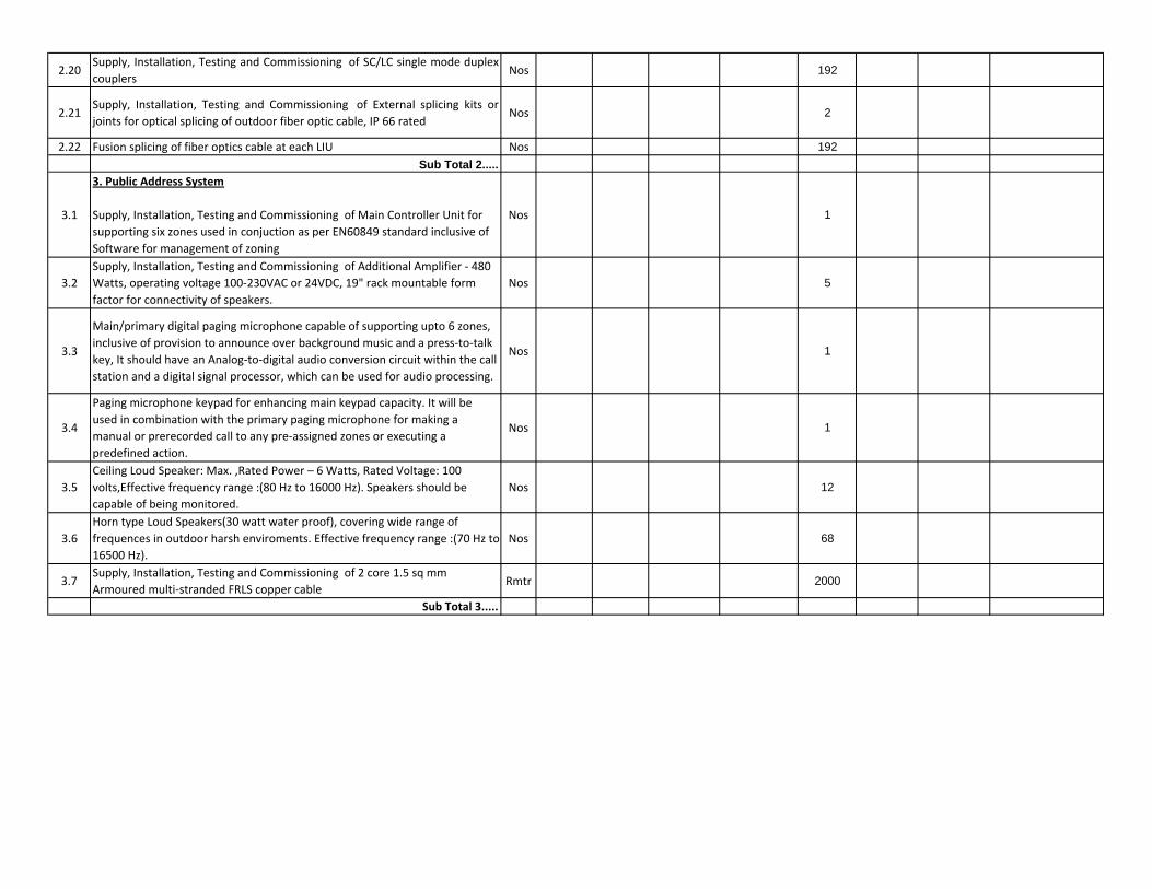
2.20Supply, Installation, Testing and Commissioning of SC/LC single mode duplexcouplers
Nos 192
2.21Supply, Installation, Testing and Commissioning of External splicing kits orjoints for optical splicing of outdoor fiber optic cable, IP 66 rated
Nos 2
2.22 Fusion splicing of fiber optics cable at each LIU Nos 192Sub Total 2.....
3.1
3. Public Address System
Supply, Installation, Testing and Commissioning of Main Controller Unit for supporting six zones used in conjuction as per EN60849 standard inclusive of Software for management of zoning
Nos 1
3.2Supply, Installation, Testing and Commissioning of Additional Amplifier ‐ 480 Watts, operating voltage 100‐230VAC or 24VDC, 19" rack mountable form factor for connectivity of speakers.
Nos 5
3.3
Main/primary digital paging microphone capable of supporting upto 6 zones, inclusive of provision to announce over background music and a press‐to‐talk key, It should have an Analog‐to‐digital audio conversion circuit within the call station and a digital signal processor, which can be used for audio processing.
Nos 1
3.4
Paging microphone keypad for enhancing main keypad capacity. It will be used in combination with the primary paging microphone for making a manual or prerecorded call to any pre‐assigned zones or executing a predefined action.
Nos 1
3.5Ceiling Loud Speaker: Max. ,Rated Power – 6 Watts, Rated Voltage: 100 volts,Effective frequency range :(80 Hz to 16000 Hz). Speakers should be capable of being monitored.
Nos 12
3.6Horn type Loud Speakers(30 watt water proof), covering wide range of frequences in outdoor harsh enviroments. Effective frequency range :(70 Hz to 16500 Hz).
Nos 68
3.7Supply, Installation, Testing and Commissioning of 2 core 1.5 sq mm Armoured multi‐stranded FRLS copper cable
Rmtr 2000
Sub Total 3.....

4.1
4. FIRE DETECTION, ALARM & CONTROL SYSTEMSupply, Installation, Testing and Commissioning of UL listed Microprocessorbased networkable analogue addressable Main Fire Alarm Control Panel asper tender specifications having minimum 2 loop capacity, each loop havingcapacity of 159 addressable detectors and 159 addressable devices.
Panel costs to inclue power supply, 24VDC power supply automatic batterycharger, 24 volts sealed lead acid batteries sufficient for 24 hours normalworking and then be capable of operating the system for 2 hours duringemergency conditions.
The system should be complete with user‐friendly programming andconfiguration tools, front panel operating with a full QWERTY keypad andalphanumeric 640 character LCD display. The Panel as well as detectors anddevices shall be UL 9th edition Approved/Listed and in conformance withinternational standards such as NFPA 72 2010 edition National Fire Alarm andSignalling Code for Human Life Safety. The complete system as a solutionmust be supplied from the same make/OEM manufacturer componentsconforming to these standards.
Nos 1
4.2Supply, Installation, Testing and Commissioning of Optical smoke detectors, complete with detector base as per tender specifications, UL certtified.
Nos 71
4.3Supply, Installation, Testing and Commissioning of Optical/Smoke and Heat Detectors (Multisensor detectors), complete with detector base for concealed spaces and plenum areas as per tender specifications, UL certified.
Nos 16
4.4Supply, installation, Testing and Commissioning of Rate‐of‐rise heat detector with mounting based LED, Address Switch inclusive of detector base and complete as required. UL or equivalent listed.
Nos 1
4.5Supply, Installation, Testing and Commissioning of Response indicators to be mounted in open and exposed areas for conceal‐mounted detectors as per tender specifications.
Nos 16
4.6Supply, Installation, Testing and Commissioning of Hooters / Electronic Sounders cum Strobes having audio + visual indication complete with addressable control modules as per tender specifications, UL certified.
Nos 36
4.7Supply, Installation, Testing and Commissioning of Manual Call point with suitable housing and glass front as per tender specifications.
Nos 36
4.8Supply, Installation, Testing and Commissioning of Short circuit and/or open circuit isolators for bypassing SC and OC situations as per tender specifications.
Nos 10
4.9
Supply, Installation, Testing and Commissioning of Remote Display consisting of 80 character backlit LCD for use with the Fire Alarm Control Panel for remote status indication, connected over 2‐wire EIA‐485 serial interface, 24VDC on same cable pair.
Nos 1

4.10Supply, Installation, Testing and Commissioning of 2 core 1.5 sq mm Armoured multi‐stranded FRLS copper cable as per tender specifications
Rmtr 3000
Sub Total 4.....
5.1
5. Video‐Surveillance / CCTV System
Supply, Installation, Testing and Commissioning of IP network cameras fixed, CS mount type, PoE, inclusive of IP66 rated housing for outdoor use as per tender specifications.
Nos 12
5.2
Supply, Installation, Testing and Commissioning of high definition format pixel PTZ network cameras, PoE and/or 24VAC operation, inclusive of IP66 rated housing for outdoor operation as per tender specifications.
Nos 4
5.3
Supply, Installation, Testing and Commissioning of Central Management application for comprehensive management of the IP surveillance network for upto 32 camera registrations including server hardware
Nos 1
5.4Supply, Installation, Testing and Commissioning of Network Attached Storage for 24 x 7 x 15 days as per specifications for achieving above storage capabilites inclusive of server hardware.
Nos 1
5.5Supply, Installation, Testing and Commissioning of 40" LED / LCD Display for Surveillance and Monitoring.
Nos 1
5.6Supply, Installation, Testing and Commissioning of Layer 2 manageableswitch, 24 x 1000Mbps ports, auto MDI/MDX, auto‐sensing, supportingminimum 4 nos. 1000Mbps Copper or OFC shared uplinks, non‐PoE
Nos 1
5.7
Supply, Installation, Testing and Commissioning of UTP CAT6 24 Portscapacity gigaspeed angular patch panel, all ports loaded with individual RJ‐45IOs. Any unused / unloaded ports should be masked with blank modules orblank IO inserts as per tender specifications
Nos 1
5.8SITC of 1000 Base LX singlemode Tranceiver for L2/L3 switch, Single mode, LCtermination supporting distance upto 2000 mtrs
Nos 2
5.9
Supply, Installation, Testing and Commissioning of Rack mounted LIU for 12core Singlemode ofc cable assembly/termination for ST, SC or LC stylecomponents, for optical splicing and provision for storage of pigtails andsplices, equipped with coupler/adaptor plates and couplers/adaptors. Anyblank coupler/adaptor positions must be suitably masked for restricting dustentry.
Nos 2
5.10Supply, Installation, Testing and Commissioning of External splicing kits orjoints for optical splicing of outdoor fiber optic cable, IP 66 rated
Nos 1

5.11
Supply, Installation, Testing and Commissioning of Industrial LIU for 12 coreSinglemode ofc cable assembly/termination for ST, SC or LC stylecomponents, for optical splicing and provision for storage of pigtails andsplices, equipped with coupler/adaptor plates and couplers/adaptors. Anyblank coupler/adaptor positions must be suitably masked for restricting dustentry.
Nos 30
5.12Supply, Installation , Testing And Commissioning of 6 port Industrial PoE‐Switch with 2 port populated mini GBIC SFP ports & 4 nos. 1000MbpsTx ports, with DC power supply..
Nos 15
5.13Supply, Installation, Testing and Commissioning of ST, SC or LC Singlemodeduplex patch cords ‐ 7ft
Nos 32
5.14Supply, Installation, Testing and Commissioning of ST, SC or LC styleSinglemode duplex pigtails ‐ 3ft
Nos 384
5.15Supply, Installation, Testing and Commissioning of ST, SC or LC Singlemodeduplex couplers
Nos 384
5.16 SITC of DC power Supply 24 VDC Nos 155.17 SITC of UTP CAT6 RJ45 Ethernet Patch Cord ‐ 7ft Nos 18
5.18 Supply, Installation, Testing and Commissioning of IP 66 rated Enclosure Nos 17
5.19Supply, Laying, Installation and Commissioning of 12 Core Singlemode OpticFiber Cable for outdoor in prelaid HDPE conduits or PVC conduits or RCCHume pipes alongwith accessories as per tender specifications
Rmtr 2500
5.20 Supply, Installation, Testing and Commissioning of 25 MM Dia. HDPE Conduit Rmtr 2200
Sub Total 5.....
6.1
6. Access Control SystemSITC of microcontroller/microprocessor base Door Controller for Access Control with all interfaces for computer/server connectivity for card base or biometric base access control. (Access Control+Time Attendance)
Nos 3
6.2Web based Software Application for System Configuration, Management & Diagnostics, Time Attendance and Leave Management Application Nos 1
6.3SITC of Electromagnetic lock 600lbs capacity with all accessories and cabling
Nos 3
6.4 SITC of Exit Switch with door controller Nos 36.5 Proximity Cards including photo‐id and other printing as per client Nos 200
6.6Intel CPU based computer with LCD monitor & laserjet printer printer for Applications ‐ Configuration and management, Time Attendance Application, Visitor Management Application.
Nos 1
Sub Total 6.....