abb low voltage (lv) bushings for pad mounted distribution transformers 600v
TRANSCRIPT

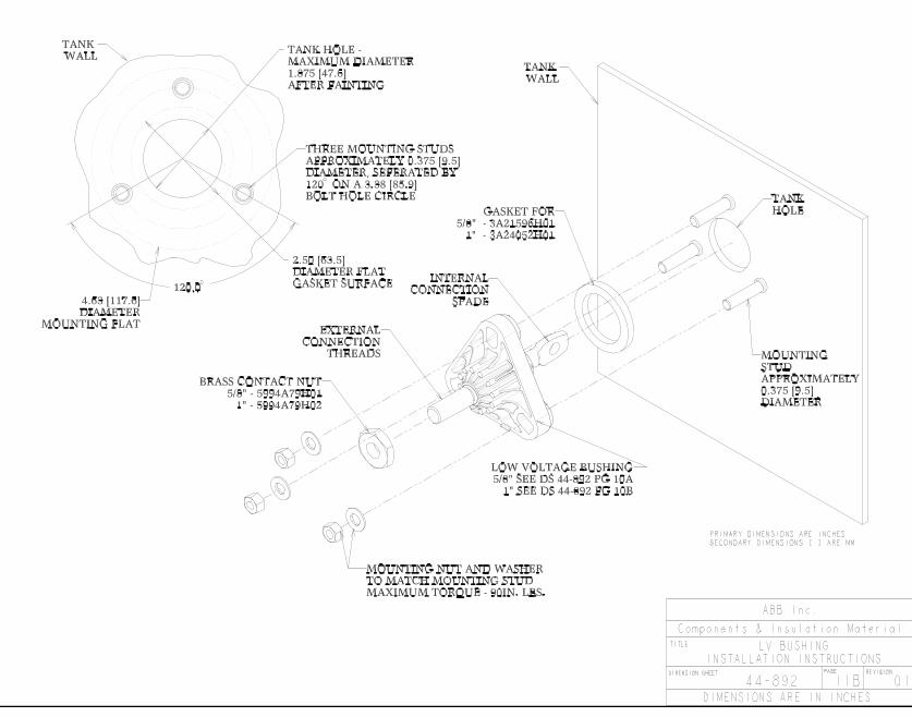
DescriptionABB low voltage bushings are molded from a high temperature, glass-reinforced nylon resin system (Dupont Zytel HTN™). The nylon body is molded around a copper stud. The copper stud is terminated at one end with a spade terminal which is used to make the internal transformer connections. The other end of the stud is threaded to accept various connectors which are used to connect to the external low voltage circuit. The bushings are available in two stud sizes: 0.625 inch diameter and 1.00 inch diameter.
RatingsConductor
Diameter (inches)
Voltage Rating
(volts)
BIL Rating
(kV)
Current Rating
(amperes)
0.625 600 30 600
1.00 600 30 1400
Test proven quality and reliabilityThe ABB low voltage bushings have passed a series of design tests which were designed to verify ratings, suitability for use on pad-mounted distribution transformers, and long term reliability.1) Seal integrity test2) Full wave impulse test3) Low frequency voltage withstand test4) Conductor stud torque test5) Cantilever load test6) Thermal cycle test7) Temperature rise test
In addition to the design testing, the following routine produc-tion tests are done on an audit basis:1) Dimension check2) Visual inspection3) Leak test
InterchangeableThe ABB low voltage bushings have been designed to be dimensionally interchangeable with the majority of similar bush-ings available on the market. Included in these interchangeable dimensions are: the bolt circle for the integral mounting flange, the tank wall hole size, the conductor stud diameter, and the external thread size.
Compact designThe bushings have been designed to minimize the space re-quired inside of the transformer. For both bushings, the dimen-sion from the inside surface of the tank wall to the end of the stud has been reduced. This reduction may allow the trans-former designer to reduce the volume of the transformer tank to save both oil and steel.
Transformer components
Low voltage bushings for pad-mounted distribution transformersTechnical information guide
ABB low voltage bushings terminate a transformer’s internal low voltage leads at the tank wall and provide a standard threaded stud for connections to the external low voltage circuit.

2 Low voltage bushings for pad-mounted distribution transformers | Technical information
Integral flangeThe mounting flange on the bushings is molded as an integral part of the bushing. This eliminates the need for a separate mounting flange and, in the case of a metal mounting flange, the associated electrical losses created by the induced current in the flange.
Compression limited gasket designsThe integral flange of the bushing has a molded-in gasket seat to ensure proper gasket location and compression during mounting. The gasket surfaces provide controlled compression and containment of the highly resilient Buna-N gasket.
Conductor lengthBushings are available with a standard or extended length thread design.
Proven nylon bodyThese ABB bushings are molded from a glass-reinforced, high temperature nylon resin (Dupont Zytel HTN). The Zytel HTN resin is a highly reliable thermoplastic that fulfills the required applica-tion needs for strength, temperature stability and low moisture absorption. The resin system retains its mechanical and electrical properties in the high temperature environment associated with pad-mounted distribution transformer applications.
CertificationTo certify the product ratings, production samples of the bush-ings were tested. The tests were conducted in accordance with ANSI/IEEE standards where applicable.
Design testsThe design tests were divided into (3) three categories:1) Dielectric tests (impulse test and 60 Hz withstand test)2) Mechanical strength tests (leak test, stud interface strength
test and cantilever test)3) Environmental tests (thermal cycle test, oil compatibility test)
Dielectric testsImpulse testThe purpose of this test is to verify the impulse withstand of the bushing. Sample bushings were subjected to three positive and three negative full wave impulses. The voltage impulse used was the standard 1.2 x 50 µs wave having the crest value of the specified voltage. The withstand voltage level of the bushings are well above the BIL rating of 30 kV. Samples successfully passed 36 kV test levels. Samples also successfully passed chopped wave tests well above the rating of 36kV.
Low frequency / 60 Hz withstand testThe purpose of the low frequency withstand test is to verify the integrity of the insulation structure of the bushing at operat-ing frequency. Bushing samples were tested at 12 kV for one minute and then allowed to rest for one minute. They were then retested for another minute. All samples passed this test.
Mechanical strength testsLeak testsThe purpose of the leak test is to ensure that, over the life of the bushing, no leak will develop between the copper stud and the nylon resin body. The bushings were tested using a helium leak detector. The sensitivity of the helium leak detector is 1 x 10⁻⁵ atm cc/sec. The bushings were attached to a leak test fixture which mates the bushing such that any leak will be detected if helium passes into the detector through the bushing. All bush-ings passed with no indication of leaks.
Stud interface strength test The purpose of this test is to verify that no damage will result when terminals are connected or removed from the bushings. The bushings were mounted in a manner simulating a typi-cal transformer installation, then a nut was threaded onto the copper stud and 50 foot-pounds of torque was applied. For the 0.625 inch diameter copper stud bushing, the stud will fail before the 50 foot-pound level is reached. For the 1.00 inch diameter copper stud bushing, the 50 foot-pound torque test was repeated 20 times.
Finally, the bushings were leak tested to verify that the seal between the copper stud and the nylon resin body was not damaged. Both the 0.625 and 1.00 inch low voltage bushings successfully passed this test.
Cantilever testThis test demonstrates the ability of the bushing to withstand the stresses generated when attaching a lead to the conductor. With the bushings mounted in a manner to simulate its appli-cation on a transformer, an extension was threaded onto the bushing stud and a load applied until failure.
The 0.625 inch bushing was mounted so that one of the mounting holes is at the 6 o’clock position. Then a cantilever load was ap-plied, resulting in the stud yielding before the bushing body failed.
The 1.00 inch bushing withstood 280 foot-pounds when mounted with one of mounting holes in the 12 o’clock position and withstood 375 foot-pounds when mounted with one of the mounting holes in the 6 o’clock position.
Technical information

Technical information | Low voltage bushings for pad-mounted distribution transformers 3
Technical information
Environmental testThermal cycle testThe purpose of the thermal cycle test is to verify the integrity of materials used in the bushing over the expected service life of the bushing. The previously leak tested bushings were sub-jected to 20 thermal cycles in air. Each thermal cycle consists of the following:1) 1-hour transition to 140 °C2) 2-hour hold at 140 °C3) 1-hour transition to -40 °C4) 1-hour hold at -40 °C
Oil compatibility testThe purpose of this test is to verify that the bushing does not have any damaging effects on the properties of the oil when the bushing is submerged in the transformer oil. The bushing passes the standard oil compatibility test.

1ZU
A27
61-6
00 –
rev.
4Note:
We reserve the right to make technical changes or modify the contents of this document without prior notice. The information, recommendations, description and safety notations in this document are based on our experience and judgment. This information should not be considered all inclusive or covering all contingen-cies. ABB does not accept any responsibility whatsoever for potential errors or possible lack of information in this document. If further information is required, ABB Inc. should be consulted.
We reserve all rights in this document and in the subject matter and illustrations contained therein. Any reproduction in whole or in parts is forbidden without prior written consent from ABB Inc.
With regard to purchase orders, the agreed particulars shall prevail. In no event will ABB Inc. be responsible to the user in contract, in tort (including negligence), strict liability or otherwise for any special, indirect, incidental, or consequential damage or loss whatsoever including but not limited to use of equipment, plant or power system, cost of capital, profits or revenues, cost of replacement power, additional expenses in the use of existing power facilities, or claims against the user by its customers resulting from the use of the information, recommendations, description and safety notations contained herein.
Copyright 2011 ABB.
All rights reserved.
For more information please contact:
ABB Inc. 1128 South Cavalier DriveAlamo, Tennessee 38001, USAPhone: +1 731 696 5561Main: +1 800 955 8399Fax: +1 731 696 5377Email: [email protected]
www.abb.com/electricalcomponents

1ZUA2761-600 – rev. 2, 13 Septem
ber 2007 7 / 10

1ZUA2761-600 – rev. 2, 13 Septem
ber 2007 8 / 10
1ZUA2761-600 – rev. 2, 13 Septem
ber 2007 9 / 10