low-voltage electrical service - hydro-québec · (low-voltage electrical service from distribution...
TRANSCRIPT

Low-VoltageElectrical ServiceStandard E.21-10
L9th editionUpdated December 2008
Produced by Direction principale – Communicationsfor Vice-présidence – Réseau de distribution

9th editionUpdated December 2008
Low-Voltage Electrical ServiceStandard E.21-10

© Hydro-Québec, December 2008All rights reserved. Reproduction authorized only for educational purposes, with acknowledgment of the source.

Table of Contents
Introduction 3
0 General Information 50.1 Application 50.2 Units of measure 50.3 Definitions 6
1 Administrative Information 111.1 General 111.2 Responsibilities of the master electrician 121.3 Available voltages 181.4 Supply over one or more distribution service loops 191.5 Number of metering points 21
2 Overhead Connections 232.1 Number of service entrances per building 232.2 Spool rack 232.3 Service entrance 262.4 Service entrance modifications 272.5 Distribution service loop 292.6 Connection provided by the customer 292.7 Connection point 302.8 Overhead-underground service entrance 322.9 Connection of equipment 34
3 Underground Connections 373.1 Service entrance 373.2 Connection point 383.3 Underground conduit system 393.4 Conduits 393.5 Pullbox and junction box 413.6 Connection box for flat-rate service 443.7 Distribution service loop 443.8 Connection 45
1

4 Temporary Connections 474.1 Application 474.2 Conditions for service 47
5 Metering 495.1 Types of metering 495.2 Choice of metering equipment 495.3 Installations with single-phase 120/240-V supply 495.4 Existing installations with three-phase 120/208-V supply 495.5 Installations with three-phase 347/600-V supply 495.6 Existing installations with three-phase, three-conductor, 600-V supply 505.7 Service box clearance 505.8 Installing metering equipment for different voltages 505.9 Permanent identification of installation components 515.10 Customer-owned low-voltage transformers 52
6 Self-Contained Metering 536.1 Supply and installation 536.2 Meter socket and fixtures 536.3 Installations with single-phase 120/240-V supply 546.4 Installations with three-phase 120/208-V supply 586.5 Installations with three-phase 347/600-V supply 59
7 Instrument Transformer Metering 617.1 Location of metering equipment 617.2 Customer equipment on supply side of metering point 627.3 Instrument transformer metering in a transformer box 637.4 Instrument transformer metering in a metal-clad substation 68
Figures Tables Work at the Connection Point Index
2

Chapters 1, 5, 6 and 7:Jean Joly, Engineer
Chapters 1, 5, 6 and 7:Denis Deslauriers, Engineer
Chapters 1, 2 and 4:Roger Desbiens, Engineer
Chapters 1 and 3:Jacques Côté, Engineer
Introduction The conditions governing electrical service are laid out in the document Conditions of Electricity Service as approved by the Régie de l’énergie in its Decision D-2008-028.
This Standard covers low-voltage electricity supply and is based on the document above and on the Hydro-Québec Distribution standards in effect.
It takes into account the conditions of application stipulated in the Québec Construction Code, Chapter V – Electricity (C22.10, latest edition), hereinafter the Code.
The following three standards have also been developed:
E.21-11, Service d’électricité en basse tension à partir des postes distributeurs (low-voltage electrical service from distribution substations) – in French only
E.21-12, Service d’électricité en moyenne tension (medium-voltage electricity service) – in French only
F.22-01, Electricity Metering for Medium- and High-Voltage Installations
The 9th edition of Standard E.21-10 is designed to provide employees, master electricians, consulting engineers and manufacturers with information on implementing or modifying low-voltage installations. It is also meant to facilitate relations between Hydro-Québec and its customers regarding such matters.
This update, in effect since December 31, 2008, incorporates new electrical service conditions approved by the Régie de l’énergie.
The content was approved by a Hydro-Québec Distribution task force and the technical content checked and validated by the engineers below.
Québec regulations take precedence over this Standard in case of conflicting interpretations, and the French version of this Standard takes precedence over the English version in the event of discrepancies.
3

4

0 General Information
0.1 Application The purpose of this Standard is to describe the technical characteristics and requirements applicable to low-voltage service supplied directly from a line anywhere within the territory served by Hydro-Québec Distribution. It also describes the technical characteristics and requirements for metering elec-tricity at a rated ampacity not exceeding 6,000 A.
A master electrician finding it impossible to comply with this Standard must, before carrying out work, contact a Hydro-Québec representative at 1 877 COURANT (1 877 268-7268) to reach a solution. The list of products approved by Hydro-Québec Distribution can be found on the Web site for master electricians (www.hydroquebec.com/cmeq). A copy can also be obtained by calling 1 800 ÉNERGIE (1 800 363-7443).
If no provision covers a given modification, the requirements for a new installation apply.
0.2 Units of measureIn this Standard, the following units of measure are used:
active power kilowatt (kW)
angle degree (°)
apparent power kilovoltampere (kVA)
conductor size American wire gauge (AWG) thousand circular mils (kcmil)
force newton (N)
length metre (m) millimetre (mm)
rated ampacity ampere (A)
voltage volt (V)
Dimensions in standard figures and drawings are given in millimetres unless stated otherwise.
5
General Information Chapter 0
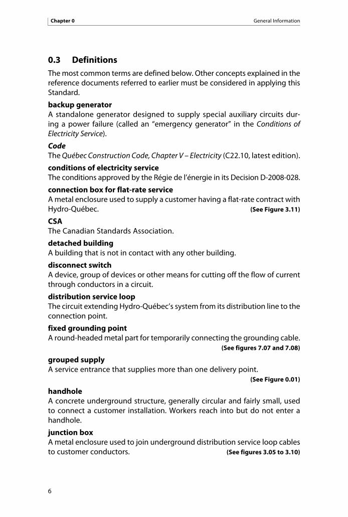
0.3 DefinitionsThe most common terms are defined below. Other concepts explained in the reference documents referred to earlier must be considered in applying this Standard.
backup generatorA standalone generator designed to supply special auxiliary circuits dur-ing a power failure (called an “emergency generator” in the Conditions of Electricity Service).
CodeThe Québec Construction Code, Chapter V – Electricity (C22.10, latest edition).
conditions of electricity serviceThe conditions approved by the Régie de l’énergie in its Decision D-2008-028.
connection box for flat-rate serviceA metal enclosure used to supply a customer having a flat-rate contract with Hydro-Québec. (See Figure 3.11)
CSAThe Canadian Standards Association.
detached buildingA building that is not in contact with any other building.
disconnect switchA device, group of devices or other means for cutting off the flow of current through conductors in a circuit.
distribution service loopThe circuit extending Hydro-Québec’s system from its distribution line to the connection point.
fixed grounding pointA round-headed metal part for temporarily connecting the grounding cable. (See figures 7.07 and 7.08)
grouped supplyA service entrance that supplies more than one delivery point. (See Figure 0.01)
handholeA concrete underground structure, generally circular and fairly small, used to connect a customer installation. Workers reach into but do not enter a handhole.
junction boxA metal enclosure used to join underground distribution service loop cables to customer conductors. (See figures 3.05 to 3.10)
6
Chapter 0 General Information
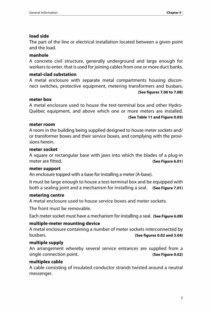
load sideThe part of the line or electrical installation located between a given point and the load.
manholeA concrete civil structure, generally underground and large enough for workers to enter, that is used for joining cables from one or more duct banks.
metal-clad substationA metal enclosure with separate metal compartments housing discon-nect switches, protective equipment, metering transformers and busbars. (See figures 7.06 to 7.08)
meter boxA metal enclosure used to house the test-terminal box and other Hydro-Québec equipment, and above which one or more meters are installed. (See Table 11 and Figure 0.03)
meter roomA room in the building being supplied designed to house meter sockets and/or transformer boxes and their service boxes, and complying with the provi-sions herein.
meter socketA square or rectangular base with jaws into which the blades of a plug-in meter are fitted. (See Figure 6.01)
meter supportAn enclosure topped with a base for installing a meter (A-base).
It must be large enough to house a test-terminal box and be equipped with both a sealing joint and a mechanism for installing a seal. (See Figure 7.01)
metering centreA metal enclosure used to house service boxes and meter sockets.
The front must be removable.
Each meter socket must have a mechanism for installing a seal. (See Figure 6.09)
multiple-meter mounting deviceA metal enclosure containing a number of meter sockets interconnected by busbars. (See figures 0.02 and 3.04)
multiple supplyAn arrangement whereby several service entrances are supplied from a single connection point. (See Figure 0.02)
multiplex cableA cable consisting of insulated conductor strands twisted around a neutral messenger.
7
General Information Chapter 0

8
Chapter 0 General Information
overcurrent protective deviceA device that automatically opens an electrical circuit under specified overload or short-circuit conditions, either electromechanically or by the melting of metal.
overhead-underground service entranceAn underground service entrance connected to an overhead line. (See figures 2.24 to 2.26)
pole-mounted substationOne or more overhead transformers installed on one or more poles.
power system or systemUnless otherwise stated, the electricity distribution system as defined in the Act respecting the Régie de l’énergie.
premisesA building, site or structure with an electrical installation to which Hydro-Québec can supply power.
pullboxAn indoor metal enclosure used to pull underground distribution service loop cables to the meter socket without splicing. (See Figure 3.01)
rated ampacityThe intensity of the electrical current indicated on the service box (referred to as “rated current” in the Conditions of Electricity Service).
readily accessible locationAn indoor or outdoor location for metering equipment that can be reached at all times through a passageway at least 600 mm wide and 2 m high and kept clear at all times. It must be accessible without having to step over or remove obstructions, use a fixed or portable ladder or employ any other such means. Snow is not considered an obstruction.
An indoor location must have adequate lighting. An outdoor location must be accessible even when the customer is away.
rooftop support structureA metal support structure fitted with insulators and installed on the roof of a building. (See Figure 2.15)
row houseA building belonging to a row of several adjacent buildings connected to each other by common walls.
semidetached buildingA building with one or more dwellings that is flanked on one side only by another building from which it is separated by a common or blank wall.

9
General Information Chapter 0
service entranceThe part of the electrical installation of the premises to be supplied, from the service box up to the connection point inclusively (referred to as “customer’s service entrance” in the Conditions of Electricity Service).
splitter boxA metal enclosure used to connect feeders. (See Figure 6.08)
spool rackA metal fixture with one or more insulators that is used to attach distribution service loop or service entrance conductors to a wall, pole, service mast or support connecting such masts. (See figures 2.01, 2.03 and 2.06)
street addressAn address with a number issued by the municipality and used to identify the exact location of a building or structure.
supply sideThe part of the line or electrical installation located between a given point and the power supply.
transformer boxA metal enclosure used to house voltage and current transformers and other Hydro-Québec equipment, and above which one or more meters are installed. (See Figure 0.04)
underground conduit systemA system of one or more conduits, laid in a trench and sometimes encased in concrete, through which distribution cables are run.

10

Administrative Information Chapter 1
11
1 Administrative Information
1.1 General
1.1.1 Request for service
The applicant must make a request to Hydro-Québec for a service contract and provide the information required under the Conditions of Electricity Service in effect.
Where a master electrician or consulting engineer makes the request, he acts as the duly authorized representative of the customer who will be the contract holder.
1.1.2 Making the request
When a written request to Hydro-Québec for a low-voltage supply contract is required for a project, it must be submitted during the planning phase.
For both written and verbal requests, the applicant must furnish the docu-ments required based on the nature of the work to be done, such as the Demande d’alimentation et déclaration de travaux (request for supply and statement of work) form, along with the information required under the Conditions of Electricity Service and this Standard.
On receiving the Demande d’alimentation et déclaration de travaux form, Hydro-Québec will connect the customer’s electrical installation, provided it complies with the requirements herein. Hydro-Québec will not ve rify the customer’s installation, notably with respect to parts of the building, blank walls, firewalls or any other specific requirement. It will assume that the mas-ter electrician or consulting engineer submitting the form mentioned above has done the work according to accepted industry practices and as specified in the Code. Any exception of any nature must be justified by an appropriate modification or written approval from the Régie du bâtiment, which the mas-ter electrician shall submit to Hydro-Québec before the connection is made.
If the Hydro-Québec representative deems that an installation on the load side of the connection point is faulty and a safety hazard, he may ask the competent authorities to verify it before the connection is made.
1.1.3 Information required
The applicant must provide the following additional information:
• Nameandaddressofthecustomer’srepresentative
• Ratedampacityoftheservicebox(specifyingifthereiscontinuousservice at 100% of that rating)

• Clearance,serviceentrancetypeandmeteringmethod
• Cadastral plan, building layout and desired connection point, on request
• For flat-rate contracts, breakdown of load by equipment type,number of equipment units connected, installed load of each unit, maximum power demand and technical drawings and specifica-tions in order to estimate power for new equipment. Such data is also required for additions or changes to a unit, or when adding or removing a unit.
Note that customers need not give their social insurance number to their duly authorized representative, but must disclose it to Hydro-Québec.
1.1.4 Costs
The customer must assume all costs set out in the Conditions of Electricity Service and the rates in effect.
1.2 Responsibilities of the master electricianBefore installing, modifying or renovating a service entrance, the master electrician must
• check the availability of electricity service and the applicableconditions;
• informthecustomerof thesteps tobe taken inorder toobtainservice at the desired date;
• tellthecustomeraboutconnectionchargesorchargesthatmaybe applied to extend or modify the line, and suggest that the customer contact Hydro-Québec for further information.
1.2.1 Breaking of seals
1.2.1.1 Breaking of metering equipment seals
The master electrician must obtain Hydro-Québec’s consent before breaking any metering equipment seal unless an unanticipated event (force majeure) occurs, in which case consent may be given after the work, before the Demande d’alimentation et déclaration de travaux form is submitted. He must enter the date the seal was broken and the authorization number (numéro de dossier) on the form.
1.2.1.2 Breaking the seal of a component on the supply side of metering equipment
The master electrician must inform Hydro-Québec of any work requir-ing that the seal be broken on one or more components installed on the supply side of metering equipment. He must enter the date
Chapter 1 Administrative Information
12

the work was done on the notice of unsealing or on the Demande d’alimentation et déclaration de travaux form, or must convey this information by phone.
1.2.1.3 Deadline
The master electrician must submit via the Web or by fax the notice of unsealing or the completed Demande d’alimentation et déclaration de travaux form within 48 hours of starting the work. For work on weekends or holidays, the document must be sent to Hydro-Québec as soon as its offices open or within the 48-hour limit. The same deadlines apply to a notice of unsealing given over the telephone.
1.2.2 Authorization
1.2.2.1 New installation
The master electrician is not authorized to connect a service entrance to the distribution service loop or line.
1.2.2.2 Requirements for connection
Only Hydro-Québec can connect a service entrance to the line.
For the connection to be made, the master electrician must do the following:
a) Demande d’alimentation et déclaration de travaux form Send Hydro-Québec a completed copy of the above form or,
for exclusions under the Building Act or the Code, a document certifying that the installation is safe and complies with good engineering practice.
b) Identification of premises Clearly display on the front of the building or structure the civic
number, project reference number or other identification accepted by the Hydro-Québec representative.
c) Identification of components Identify service boxes, transformer boxes, meter sockets and dis-
tribution panels as stipulated in Section 5.9.
d) Sealing Install a mechanism for installing a seal on components that are
on the supply side of metering equipment and allow access to energized conductors and devices.
These components include service boxes, transformer boxes, meter boxes and meter sockets, as well as pullboxes, junction boxes, flat-rate connection boxes and splitter boxes that are on the supply side of metering equipment.
Administrative Information Chapter 1
13

It must also be possible to affix self-adhesive seals to LB, LL and LR conduit bodies installed indoors. (See Figure 3.02)
1.2.2.3 Reconnecting after a disconnection
If electricity delivery resumes more than 12 months after service was terminated or if Hydro-Québec so requires, the applicant must submit the Demande d’alimentation et déclaration de travaux form and comply with the rules set out herein.
Subject to the above paragraph and if electricity delivery resumes less than 12 months after service was terminated, Hydro-Québec agrees to connect a customer’s electrical installation that does not comply with the requirements herein, provided that
• doingsodoesnotcompromisesafety;• nomodificationwasmadebetweentheconnectionpointandthe
main service box; and• nomodificationtothebuildingorstructurehasmadetheelectri-
cal installation non-compliant.
1.2.2.4 Reconnection by a master electrician
A master electrician may disconnect and reconnect at the connection point an overhead service entrance he is modifying or renovating, provided that he
• first obtains Hydro-Québec’s consent unless an unanticipatedevent (force majeure) occurs, in which case consent may be given after the work, before the Demande d’alimentation et déclaration de travaux form is submitted;
• checks when reconnecting that the distribution service loopconsists of insulated conductors whose ampacity is at least that of a 2 AWG aluminum conductor (if this is not the case, refer to Section 1.2.2.6);
• makessurethattheconnectionpointislocatedonthedistributionservice loop (120/240 V, 200 A or less);
• doesnotlengthen,shortenormovethedistributionserviceloop(if any such change is necessary, the new service entrance must be supplied temporarily from the existing connection point);
• keepsdistributionserviceloopconductorsoffthegroundduringand after the work;
• takes the precautions needed to ensure public safety and tomaintain standard clearance; and
• meetstherequirementsinTables12and13,andunderthesection“Work at the Connection Point” herein.
Chapter 1 Administrative Information
14

If an unanticipated event affects an installation and the distribution service loop or connection point connectors are damaged, the master electrician is not authorized to repair the connectors but must notify Hydro-Québec, which will take the necessary measures.
An unanticipated event (force majeure) is a weather event, catastro-phe (fire, flood, etc.) or fortuitous incident caused by a third party or a customer, who must undertake urgent or unforeseen repair work as a result.
1.2.2.5 Modification or subsequent work
For a modification that entails changing the size or capacity of the service entrance or for work carried out after initial installation of the distribution service loop (adding a meter, or conducting repair, maintenance or other work), the master electrician may break the seal on any metering equipment, and de-energize and remove it, subject to Section 1.2.1.1.
The master electrician must then ensure that the metering equipment is in good condition and leave it in view near the electrical installation with the seal intact, so Hydro-Québec can recover it.
He must not reconnect metering equipment that includes current transformers regardless of the supply voltage.
1.2.2.6 Temporary supply circuits
If a modification entails transferring load from an existing to a new connection, Hydro-Québec will refuse to hook up even temporarily more than one connection of the same voltage, in accordance with Section 1.4.1.1. In such a case, temporary supply circuits connected to permanent installations or generator sets must, without exception,
• havereceivedHydro-Québec’spriorauthorization;
• complywith theCode, specifically Section 76, and with require-ments regarding warning signs;
• be connected to the existing connection point, if necessary, provided there is a distribution service loop conductor;
• notbe interconnectedwith theexistingmeter socket,meteringtransformer box or service box;
• beinstalledinawaythatensurespublicsafetyandcomplieswithany required clearance; and
• be installedwith the protective equipment and tools needed toconnect the temporary cabling safely.
Administrative Information Chapter 1
15

Under no circumstances is the master electrician authorized to lengthen, shorten or move the existing distribution service loop to connect a tem-porary circuit to supply an existing installation. He must take the neces-sary measures to ensure that the installation complies with the Code, specifically regarding the ampacity of the existing distribution service loop, until such time as Hydro-Québec installs the new loop conductor.
Once the new connection is in place, the material (like temporary cabling and connectors) must, to the extent possible, be left on site or in a predetermined location so the owner can recover it. (See Figure 1.04)
1.2.3 Electricity generation
Applicants must obtain Hydro-Québec’s written consent before connecting electricity generating equipment in parallel with the line. The connection and use of such equipment must at all times comply with conditions set by Hydro-Québec and with the standards in effect.
1.2.3.1 Backup generators
Any backup generator a customer installs must be equipped with a manual or automatic transfer switch meeting Hydro-Québec requirements. A transfer switch may include one or more distinct devices installed so as to prevent the normal power supply from interconnecting with the backup generator.
Backup generators must always be installed on the load side of meter-ing equipment, which must be de-energized whenever a backup generator is running. Safety precautions are covered in Section 7.3.4. (See Figure 1.01)
1.2.4 Quality of service
1.2.4.1 General
Under the Conditions of Electricity Service, the customer’s electrical installation must be designed, built, connected, protected, used and maintained in such a way that it does not cause disturbances on the power system.
Disturbances can be caused by a number of phenomen: voltage and current fluctuations, flicker, harmonics, etc.
In order to maintain power quality, Hydro-Québec must ensure compliance with the limits for the various types of disturbances on its power system. Based on the information regarding load type provided on the form Demande d’alimentation et déclaration de travaux (request for supply and statement of work), Hydro-Québec may ask the customer to conduct any necessary studies.
Chapter 1 Administrative Information
16

Even if no studies are required by Hydro-Québec, the customer must comply with the requirements set out in sections 1.2.4.2 and 1.2.4.3 below.
1.2.4.2 Voltage fluctuations and flicker
Customers supplied at low voltage directly from the power line must not, without Hydro-Québec’s written consent, connect a load that is apt to cause an inrush current of 100 A or more. Such consent is not required for low-voltage inrush currents of less than 100 A, such as those drawn by 2-hp 120-V motors, 5-hp 240-V motors, 15-hp 347/600-V motors and 15-hp 600-V motors. Consent is required for any motor with a higher rating than those mentioned.
1.2.4.3 Unbalanced loads
Unless Hydro-Québec has otherwise authorized in writing, customers with a three-phase supply must limit the phase-to-phase current imbalance to 10% of the rated ampacity. The imbalance must not, however, exceed 50 A if the service box rating exceeds 600 A and the customer has undertaken not to exceed a demand current of 500 A (or 600 A during the winter period for a dual-energy system). This limit is 60 A for service supplied from a 600-A pole-mounted distribution substation. In buildings with multiple metering points, phase imbalance is measured at the connection point.
1.2.5 Protection coordination
The type, features and settings of the customer’s protection equipment must enable coordination between customer installation protection and transformer substation protection.
For service supplied directly from the power line, the electrical installation’s protective device must ensure a minimum 22,000-A interrupting capacity.
At Hydro-Québec’s request, however, the customer must install a protective device with a higher interrupting capacity.
For service boxes rated higher than 600 A, the customer must send Hydro-Québec the following documented information as soon as possible after submitting a request for service:
a) Primary protection specifications Type of switch or circuit breaker, manufacturer, model, rated
ampacity, interrupting capacity and rated voltage
b) Primary protection settings Relay settings, fuse rating and time-amperage curves
To coordinate Hydro-Québec transformer substation protection with the customer’s primary installation protection, the latter may be lowered.
Administrative Information Chapter 1
17
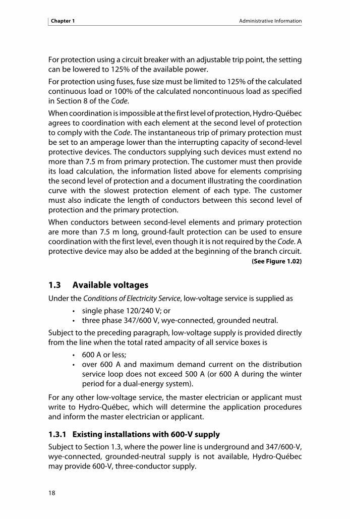
For protection using a circuit breaker with an adjustable trip point, the setting can be lowered to 125% of the available power.
For protection using fuses, fuse size must be limited to 125% of the calculated continuous load or 100% of the calculated noncontinuous load as specified in Section 8 of the Code.
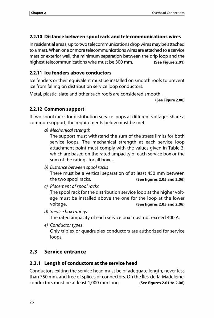
When coordination is impossible at the first level of protection, Hydro-Québec agrees to coordination with each element at the second level of protection to comply with the Code. The instantaneous trip of primary protection must be set to an amperage lower than the interrupting capacity of second-level protective devices. The conductors supplying such devices must extend no more than 7.5 m from primary protection. The customer must then provide its load calculation, the information listed above for elements comprising the second level of protection and a document illustrating the coordination curve with the slowest protection element of each type. The customer must also indicate the length of conductors between this second level of protection and the primary protection.
When conductors between second-level elements and primary protection are more than 7.5 m long, ground-fault protection can be used to ensure coordination with the first level, even though it is not required by the Code. A protective device may also be added at the beginning of the branch circuit. (See Figure 1.02)
1.3 Available voltagesUnder the Conditions of Electricity Service, low-voltage service is supplied as
• singlephase120/240V;or• threephase347/600V,wye-connected,groundedneutral.
Subject to the preceding paragraph, low-voltage supply is provided directly from the line when the total rated ampacity of all service boxes is
• 600Aorless;• over 600 A and maximum demand current on the distribution
service loop does not exceed 500 A (or 600 A during the winter period for a dual-energy system).
For any other low-voltage service, the master electrician or applicant must write to Hydro-Québec, which will determine the application procedures and inform the master electrician or applicant.
1.3.1 Existing installations with 600-V supply
Subject to Section 1.3, where the power line is underground and 347/600-V, wye-connected, grounded-neutral supply is not available, Hydro-Québec may provide 600-V, three-conductor supply.
Chapter 1 Administrative Information
18

An addition or change can be made to an existing 600-V, three-conductor supply insofar as no change is made between the connection point and the main service box or to the main service box itself. In such cases, however, a neutral conductor must be installed as stipulated in Section 7.3.2.9 b).
1.3.2 Existing installations with 120/208-V supply
Subject to Section 1.3, an addition or change can be made to an existing 120/208-V, wye-connected, grounded-neutral supply insofar as no change is made between the connection point and the main service box, or to the main service box itself.
When an addition or change leads to a modification between the connection point and main service box, the master electrician can reconnect the existing 120/208-V installation to a new 347/600-V, wye-connected, grounded-neutral supply as shown in Figure 1.03.
Adding a transformer to measure the voltage at 120/208 V is prohibited, however, if there is no metering facility at that voltage on the customer’s premises. For any other addition to an existing supply, metering must be at 120/240 V or 347/600 V. (See Figure 1.03)
1.4 Supply over one or more distribution service loops
1.4.1 Service loops from the line
1.4.1.1 Supply at two voltages
Subject to Section 1.4.1.2, a single building cannot be supplied at a given voltage over more than one distribution service loop. Hydro-Québec thus installs a single service loop per voltage per building. It will, however, provide both single-phase and three-phase supply to a single building.
1.4.1.2 Additional service loops
Hydro-Québec may agree to an additional service loop with a separate metering point in the cases below:
a) Fire pumps and emergency power systemsAn additional service loop may be provided from the power line if the main loop is connected to the line or is a medium-voltage loop. Fire alarm, emergency lighting and other emergency systems can be supplied over the additional service loop.
The loop dedicated to emergency power is supplied in most instances from the same transformer as the main service loop. The building load can be interrupted by disconnecting the main
Administrative Information Chapter 1
19

service loop. The emergency loop is left energized so that the fire pump and other emergency systems are not interrupted, provided the emergency loop is clearly identified with color coding.
When circumstances so require, however, Hydro-Québec can interrupt power to this loop.
b) Industrial plants and other complex structures An additional service loop may be installed for complex structures
such as industrial plants, commercial buildings and shopping centres with adjacent parking lots, on condition that the cus-tomer provide Hydro-Québec with technical reasons justifying its necessity. Thus, buildings comprising several parts, often built in successive phases and sometimes having different uses, may be connected to the power system by more than one distribution service loop. Each part supplied by a separate service loop must be independent and not connected to any other service box.
c) Independent units in a building• Suchunitsmustnotbeoneabovetheother.• Theymusthaveaprivateentranceanddirectground-levelaccess.
Each unit must be equipped with a separate electrical installation and be independent, with no connection to another service box.Independent units may have different uses (e.g., residential or commercial). Firewalls between units are not mandatory if the conditions above are met.
It must be noted, however, that in accordance with requirements in Section 1 of the Québec Construction Code, any unit separated by firewalls is consid-ered a separate building. There may then be one service loop per building.
If more than one distribution service loop is installed for a single building, all services boxes must be grouped, if possible. If two or more service boxes are not grouped, a permanent drawing must be posted on or near each service box to show where all other service boxes are located.
1.4.2 Service loops from one or more distribution substations
Refer to Standard E.21-11, Service d’électricité en basse tension à partir des postes distributeurs (low-voltage electrical service from distribution substations).
1.4.3 Distribution service loops – Termination of special rates
Customers who are no longer entitled to a special rate or elect to forgo it can keep the distribution service loop, provided that
• anappropriatemeteringmethodispossibleovertheloop;and• thecapacityofthebuilding’sserviceboxesdoesnotneedtobe
increased.
Chapter 1 Administrative Information
20
The installation connected to such a service loop is covered by a separate contract and is subject to the applicable rate for the intended use.
If any of the service boxes must be modified, all service boxes must be grouped on a single service loop.
Hydro-Québec reserves the right to modify the substation serving such a service loop.
1.5 Number of metering pointsAt a given location and voltage, only one metering point is authorized per customer, except
• whentheintendedusesandapplicableratesdiffer;• whenserviceisfrommorethanonedistributionsubstation;or• inthecasessetoutinSection1.4.1.2.
21
Administrative Information Chapter 1

22

2 Overhead Connections
2.1 Number of service entrances per building
2.1.1 New service entrances
The number of low-voltage service entrances connected to an overhead dis-tribution service loop supplying a building depends on the following factors:
• ThetotalloadcalculatedbasedontheCode must not exceed 600 A.
• Thenumberofconductorsconnectedtothedistributionserviceloop conductor must not exceed four. (See Figure 0.02)
2.1.2 Modified service entrances
If a service entrance with more than four conductors connected to a dis-tribution conductor must be modified, the conductors may be replaced provided their number remains unchanged and the total load calculated based on the Code does not exceed 600 A.
2.2 Spool rack
2.2.1 Supply and installation
The master electrician shall, at the customer’s expense, supply and install the spool rack in accordance with Code requirements and with the recom-mendations of the Régie du bâtiment du Québec, particularly to avoid any problem due to vibrations. The customer retains ownership of the spool rack.
2.2.2 Location
The spool rack may be attached to the exterior wall of a building or to a customer pole, service mast or other support structure. The master electrician shall ensure that the service loop is secured firmly to the building in a location not conducive to vibrations, and shall strengthen the structure, if necessary, at the customer’s expense. The location must also allow the meter to be installed in a readily accessible place.
2.2.3 Clearances
The location of the spool rack must always comply with clearances specified in CAN/CSA-C22.3 No. 1 (latest edition) and in the Code when the distribu-tion service loop runs over lots, roads, appurtenant structures, pools or any other obstacle or constraining element.
23
Overhead Connections Chapter 2

The distribution service loop must never run above a customer’s building or an appurtenant structure, with the following exceptions:
• Conductorsenteringabuildingcanrunaboveit.
• The distribution service loop can run above the eaves no fartherthan 1 m from the edge of the roof, without going past the edge of the adjacent wall.
If the requirements herein cannot be met, the connection point must be located at the supply point and the service entrance must comply with Section 2.6.
This Section does not include appurtenant structures of less than 13 m2 that can be moved at any time at Hydro-Québec’s request. The minimum vertical clearance between the highest point of the structure and the distribution service loop conductor must then be 1 m above areas normally inaccessible, i.e., areas only accessible using a ladder or something else not permanently fixed in place, and 2.5 m above accessible areas, e.g., a flat roof. (See figures 2.16 and 2.18)
2.2.4 Distance between spool rack and service head
The spool rack must be attached 150 to 300 mm below where the customer conductors exit the service head. A wall-mounted spool rack must be bolted to the same wall as the service head, no farther than 300 mm from the first conduit. If there are additional conduits, the minimum length of conduc-tors exiting a service head must be increased by the distance between the conduit nearest the spool rack and the conduit in question. The distance between the spool rack and the farthest conduit must not exceed 750 mm. (See figures 2.01 to 2.06)
2.2.5 Common spool rack
2.2.5.1 Semidetached buildings and row houses
For semidetached buildings and row houses, two service entrances can share a single spool rack mounted between their respective service conduits or at their common wall. (See Figure 2.03)
2.2.5.2 Two-conduit service entrances
For service entrances with two metal conduits, a common spool rack can be installed between the two, provided they have a diameter of 50 mm or more as stipulated in the Code. (See Figure 2.04)
2.2.6 Distance between two spool racks
When spool racks for different voltages are installed side by side on an exterior wall or on masts and the required 450-mm vertical separation is not feasible, a minimum 1-m horizontal separation is required. If the spool racks are at
24
Chapter 2 Overhead Connections

different heights, the one for the distribution service loop at the higher voltage must be installed above the one at the lower voltage. (See Figure 2.06)
2.2.7 Mechanical strength
At the distribution service loop attachment point, the spool rack and any fixture supporting it must have the minimum strength specified in Table 3 for different service box ratings. A service mast must be installed using three mast clamps as specified in the Code. Wall-mounted spool racks must be bolted in place at two or more anchor points.
2.2.8 Height of spool rack
2.2.8.1 Minimum height
For adequate clearance above the ground, the spool rack must be at the minimum height specified in Section 2.7 and Table 4 for service loops of different lengths. (See figures 2.01 to 2.06)
2.2.8.2 Maximum height
The spool rack must never be attached more than 8 m above the ground. (See figures 2.01 to 2.06)
2.2.8.3 Special cases
The master electrician shall consult a Hydro-Québec representative for any case not covered by Table 4 and for the following cases:
a) Slope If the spool rack support is lower than the distribution pole or if
the distribution service loop crosses a street. Hydro-Québec may then have to install a pole on the service entrance side to meet the requirements in Table 5.
b) Obstructions If the service loop passes over a pool, appurtenant structure or
other obstacle or constraining element.
2.2.9 Conductor clearance above roofs
2.2.9.1 Mast-mounted spool rack
A mast-mounted spool rack must be at least 915 mm above the roof, and the bottom of the drip loop must be at least 600 mm above the roof. (See figures 2.01, 2.02, 2.04 and 2.05)
2.2.9.2 Gable-roofed buildings
When the service mast enters through the roof, the spool rack must be positioned such that there is 915 mm of clearance between the distri-bution service loop along its entire length and the eaves, and 600 mm of clearance from the bottom of the drip loop. (See Figure 2.07)
25
Overhead Connections Chapter 2
2.2.10 Distance between spool rack and telecommunications wires
In residential areas, up to two telecommunications drop wires may be attached to a mast. When one or more telecommunications wires are attached to a service mast or exterior wall, the minimum separation between the drip loop and the highest telecommunications wire must be 300 mm. (See Figure 2.01)
2.2.11 Ice fenders above conductors
Ice fenders or their equivalent must be installed on smooth roofs to prevent ice from falling on distribution service loop conductors.
Metal, plastic, slate and other such roofs are considered smooth. (See Figure 2.08)
2.2.12 Common support
If two spool racks for distribution service loops at different voltages share a common support, the requirements below must be met:
a) Mechanical strength The support must withstand the sum of the stress limits for both
service loops. The mechanical strength at each service loop attachment point must comply with the values given in Table 3, which are based on the rated ampacity of each service box or the sum of the ratings for all boxes.
b) Distance between spool racks There must be a vertical separation of at least 450 mm between
the two spool racks. (See figures 2.05 and 2.06)
c) Placement of spool racks The spool rack for the distribution service loop at the higher volt-
age must be installed above the one for the loop at the lower voltage. (See figures 2.05 and 2.06)
d) Service box ratings The rated ampacity of each service box must not exceed 400 A.
e) Conductor types Only triplex or quadruplex conductors are authorized for service
loops.
2.3 Service entrance
2.3.1 Length of conductors at the service head
Conductors exiting the service head must be of adequate length, never less than 750 mm, and free of splices or connectors. On the Îles-de-la-Madeleine, conductors must be at least 1,000 mm long. (See figures 2.01 to 2.06)
26
Chapter 2 Overhead Connections

2.3.2 Length of service mast
The length of the mast above the roof from the upper mast clamp to the spool rack must not exceed 1.5 m, unless the mast is guyed. (See Figure 2.01)
2.3.3 Types of service masts
Prefabricated metal masts, angle irons or steel conduits are acceptable.
Wooden masts are not allowed for new installations, modifications or replacements.
In this Section, an angle iron is considered a type of mast when the spool rack is attached to it. “Angle iron” denotes a right-angled metal section whose mechanical strength meets the requirements given in Table 3.
Steel conduits must have a minimum diameter of 63.5 mm and comply with the Code. (See figures 2.01, 2.02, 2.04, 2.05 and 2.07)
2.3.4 Metal conduit with PVC section
Metal conduits or prefabricated service masts that are electrically isolated from the service box or meter socket by a section of PVC conduit must be connected to the neutral conductor with a ground-wire clamp.
O-Z/Gedney G350B, Microelectric Canada MM700 or equivalent ground-wire clamps are acceptable. Galvanized steel clamps of the same type are also permitted. (See Figure 2.01)
2.3.5 Insulation of neutral conductor
In a saline environment or when a tingle voltage filter is used, the service entrance neutral conductor must be insulated and identified as specified in the Code. (See Figure 2.09)
In a saline environment, the insulated neutral conductor must be connected to the meter socket but not cut. However, if the meter socket does not have a detachable terminal block, the neutral conductor must be continuous in the socket. The master electrician must then run another conductor from the ground terminal block in the service box to the one in the meter socket to ensure a continuous ground.
For Hydro-Québec, a saline environment corresponds to a 1.6-km strip of land along the shoreline or coast of any saltwater body. Saline environments include the land along the St. Lawrence River east of the Rivière Saguenay on the north shore and from Rimouski to Bonaventure on the south shore, along with the south coast of the Gaspésie and the Îles-de-la-Madeleine.
2.4 Service entrance modificationsIn this Section, the term “modification” excludes replacing a faulty service entrance component by another with the same characteristics.
27
Overhead Connections Chapter 2

In cities like Montréal, which have programs or agreements for power system relocation and/or undergrounding, it is best that the master electrician contact a Hydro-Québec representative before determining any new connection point.
2.4.1 One connection point
Modifications made to one or more service entrances in a multiple supply arrangement must allow for connection to the existing connection point, provided that point meets the conditions herein. If it does not meet the con-ditions, a new connection point is determined. The master electrician must then supply the unmodified entrance(s) from that point. (See Figure 2.10)
2.4.2 More than one connection point
2.4.2.1 Unchanged number of connection points
If more than one distribution service loop supplies a building at the same voltage, modifications to one or more service entrances must not result in increasing the number of such loops. (See Figure 2.14)
2.4.2.2 Single connection point
All modified service entrances must be connected to a single point in accordance with the requirements herein.
2.4.2.3 Selection of connection point
If only two connection points comply with the requirements herein and there is only one service entrance at each point, the modified entrance must be grouped with the unmodified one.
If two or more connection points comply with the requirements herein, the point with the greatest number of service entrances must be selected. (See figures 2.11 to 2.14)
2.4.3 Service entrances on existing rooftop support structures
2.4.3.1 Rooftop support structure not more than 8 m above ground
The connection point is located at the top of the rooftop support structure, provided that point is no more than 8 m above ground level. Hydro-Québec will connect its service loop there, provided there is at least 1 m of clearance between the loop and parapet wall and at most 1 m horizontally between the connection point and the edge of the roof. (See Figure 2.15)
2.4.3.2 Rooftop support structure more than 8 m above ground
If the rooftop support structure is more than 8 m above ground level, the connection point is located at either
a) a spool rack, if the spool rack is attached in accordance with Section 2.2.8; or
28
Chapter 2 Overhead Connections

b) the supply point, if, based on prior agreement with a Hydro-Québec representa-
tive, the customer provides the connection to the supply point in accordance with Section 2.6.
2.5 Distribution service loop
2.5.1 Supply and installation
Hydro-Québec supplies and installs a service loop extending to the connec-tion point on the customer’s spool rack, and retains ownership of the loop. If Hydro-Québec is not authorized to run an overhead line across a public thoroughfare, it must provide, at the customer’s expense, an underground crossing meeting Section 3 requirements.
2.5.2 Clearance
A customer who installs a pool, appurtenant structure, platform or stand below or beside the distribution service loop must ensure it complies with Section 2.2.3. (See Figure 2.06)
2.6 Connection provided by the customer
2.6.1 Supply and installation
Customers may elect to extend their service entrance by providing the con-nection up to the connection point determined by Hydro-Québec. (See Figure 2.17)
2.6.2 Conditions
The connection provided by the customer must not cross a public thorough-fare unless municipal bylaws and Transport Department standards so permit and clearances comply with the Code. For the purposes of this Section, lanes where there are no homes with a street address are not considered public thoroughfares.
If necessary, Hydro-Québec may extend its line according to the conditions set out in Table 5.
When the customer provides an overhead (or overhead-underground) con-nection, metering equipment must be installed no more than 30 m from the line in accordance with the requirements herein.
This requirement does not apply to
• aresidence;• anoverheadconnectionfullyvisiblefromtheconnectionpoint;or• anoverhead connectionpartly visible from the connectionpoint
if the remaining part is visible from the metering point.29
Overhead Connections Chapter 2

A connection provided by the customer must not put excessive mechanical stress on the line. To remain within allowable limits, the service line span closest to the line must not exceed the lengths given in Table 6. Stress must be between 300 N (31 kg) and 450 N (46 kg) at the time of installation. If spans farther away exceed these values, the pole closest to the line must be guyed and the customer may install one or more additional poles. (See Figure 2.17)
In such cases, the voltage measured at the connection point is considered to be the voltage at the supply point. Those voltages are given in Table 2.
2.7 Connection point
2.7.1 Access to connection point
The connection point must be accessible using a ladder resting on the ground or a bucket truck, and must
• belocatednomorethan1mfromtheedgeoftheroof;• notbeoveranotherbuilding;• beclearofanysnowbankorice,forsafetyreasons;and• beatasufficientdistancefromthenearesttrees.
To be accessible using a bucket truck, the connection point must be no farther than 3 m from a passable road. It must be possible to operate the bucket truck in a space free of such obstructions as trees and fences. (See figures 2.18 and 2.19)
It is recommended that the connection point be located as close as possible to one end of the building to facilitate landscaping or pool installation, and for aesthetic reasons. (See Figure 2.20)
For access by ladder to the connection point, the area where the ladder is used between the property line and the edge of the roof or the wall against which the ladder leans must be free of any obstructions, allowing use in accordance with the Safety Code for the Construction Industry.
Section 3.5.6 d) of that document stipulates that “any ladder shall […] when not permanently fastened, be so inclined […] that the horizontal distance between the base of the ladder and the vertical plane of its top support is approximately between 1/4 and 1/3 of the length of the ladder between its supports.” Under this Section, the base can only be located on the customer’s property or in a road or lane.
For distribution service loops, access to the connection point may differ from access to meters. (See Table 8 and Figure 2.21)
30
Chapter 2 Overhead Connections

2.7.2 Location
2.7.2.1 On the nearest wall
The connection point may be located on the wall nearest the power line, either directly or on a mast, provided that the clearances in Table 4 are maintained. (See Figure 2.18)
2.7.2.2 On an adjacent wall
The connection point may be located on a wall adjacent to the wall nearest the line and at a distance not exceeding 3 m from the nearest wall, provided the distribution service loop conductors form at least a 5° angle with that adjacent wall. The distance may be greater provided the distribution service loop conductors form at least a 15° angle with the wall. For clearance values, refer to Table 7. (See Figure 2.18)
2.7.2.3 On a mast mounted on an adjacent wall
When the connection point is on the spool rack attached to a service mast mounted on an adjacent wall, the distribution service loop must not run above the roof but may run above the eaves over the wall on which the mast is mounted. (See figures 2.18 and 2.19)
2.7.2.4 Above an adjoining structure
The distribution service loop may run above an appurtenant struc-ture adjoining a building, over a distance of no more than 1 m from the edge of that structure’s roof, provided it does not cross the entire width of the structure. (See Figure 2.18)
2.7.2.5 On a customer’s pole
The connection point may be located on a customer’s pole, provided that the pole
• isnofartherthan3mfromapassableroad(includingadriveway)and is accessible at all times from a bucket truck;
• is installed no farther than 30 m from the distribution line orproperty line, whichever is to the customer’s advantage;
• isclass7orbetterunderCSA-O15-05;• isburiedatadepthofatleast1.7m;• is installedsuchthat thedistributionservice loopcomplieswith
the heights given in Table 4; and• isguyedifstressfromtheserviceentrancecoulddestabilizethe
line, as indicated in Table 6. (See Figure 2.22)
31
Overhead Connections Chapter 2

2.7.2.6 On the power line
If the customer elects to extend the service entrance to the line, the connection point is located at the supply point and the customer retains ownership of and responsibility for the connection provided. (See Figure 2.17)
2.7.3 Clearance
The connection point must be located so that there is at least 1 m of clearance between the distribution service loop conductors and any windows, doors and porches, unless the conductors are higher than these structures. Furthermore, there must be 1 m of horizontal clearance between the distribution service loop and any veranda, balcony, terrace or stairway for which a vertical clearance of 2.5 m with the conductors is not feasible. (See Figure 2.23)
2.8 Overhead-underground service entranceWhen there is an overhead line and an overhead-underground service entrance, the latter must be installed on the utility pole, provided that the following conditions are met:
a) Authorization The customer must obtain authorization from the owner of the
pole to use it.
b) Compliance with standards Installation must be carried out by a master electrician at the
customer’s expense and in accordance with standards set out by Hydro-Québec, the pole owner (Bell Canada, Bell Aliant, Télébec or Telus) and government bodies. (See figures 2.24 to 2.26)
c) Preliminaries Before starting the work, the master electrician must always check
with a Hydro-Québec representative to see what requirements apply to the installation location.
The pole owner systematically refuses any customer request for an overhead-underground service entrance from a pole which already has underground risers or equipment other than trans-formers or street lights.
d) Space on the pole The pole must have enough free space to accommodate the conduits.
No meter socket, protective device or disconnect switch can be mounted on the pole.
32
Chapter 2 Overhead Connections

e) Crossing public thoroughfares The overhead-underground service entrance must never cross a
public thoroughfare unless the customer obtains authorization from the municipality or the Ministère du Transport.
f) Requirements The overhead-underground service entrance must be installed in
accordance with technical, safety and operating requirements.
The master electrician must ensure that fill around the pole is restored to its initial condition.
g) Address The customer’s street address or equipment identification label
must be posted near underground riser conduits.
A metal tag with engraved or permanently glued digits at least 38 mm high, nailed to the pole near the riser in question, is accept-able. The owner’s name, type of equipment and street address of the closest building must be shown to identify the equipment.
If these conditions cannot be met, the customer must install, at his expense, his own pole and conduits in accordance with applicable standards.
2.8.1 Technical requirements
2.8.1.1 Number and types of conduits
No more than two service conduits may be installed on a pole. The remaining space is reserved for telephone and cable distribution companies, which can each install one riser.
Rigid metal conduits must be used and must be installed as specified in the Code. (See figures 2.24 to 2.26)
2.8.1.2 Distance between conductors and service head
There must be at least 150 mm between distribution conductors and the service head.
It is important to maintain a minimum vertical separation of 1,000 mm between all conductors, including drip loops, and telecommunication cables. The master electrician must reach a prior agreement with a Hydro-Québec representative to ensure this requirement is met when installing the service head. (See figures 2.24 to 2.26)
2.8.1.3 Conductor length
Conductors exiting the service head must be at least 1.5 m long when the line consists of separate conductors, and 750 mm long when it consists of multiplex conductors or when the connection is
33
Overhead Connections Chapter 2

to be made with transformer secondary terminals. Hydro-Québec supplies conductors to run from those exiting the service head to the transformer terminals. (See figures 2.24 to 2.26)
2.8.1.4 Metal conduit
The metal conduit must be connected to the neutral conductor using a ground-wire clamp. (See figures 2.24 to 2.26)
2.8.2 Safety requirements
The master electrician must take the necessary steps with Hydro-Québec to ensure that work is done in accordance with the Safety Code for the Construction Industry (R.Q. c. S-2.1, r. 6), which applies to all work done on a construction site as defined in the Act Respecting Occupational Health and Safety (R.S.Q., c. S-2.1), and with the Regulation Respecting Occupational Health and Safety (R.Q. c. S-2.1, r. 19.01), which applies to all institutions, subject to provisions to the contrary.
Under Section 331 of the last regulation above, any work carried out near a power line must be done in accordance with Section V of the Safety Code for the Construction Industry.
The employer must ensure that no one carries out work that could result in a part, load, scaffolding, machinery component or individual coming within 3 m of bare conductors on a power line at a maximum phase-to-phase voltage of 125 kV. Section 5.2.2 of the Safety Code for the Construction Industry, however, lists conditions where this distance does not apply.
Charges for safety work under this Section are set by Hydro-Québec and billed to the customer. (See Section 1.2.2)
2.8.3 Connection point
The connection point is located at the supply point or on the customer’s pole in accordance with Section 2.7.2.5. (See figures 2.24 to 2.26)
2.9 Connection of equipmentWith overhead lines, the connection of pole-mounted equipment, apart from street lights, must meet the conditions below. Such equipment may include cable television or telecommunications equipment, amplifiers, boosters, decorative municipal lighting, sign lights or traffic lights.
a) Compliance with standards Installation is at the customer’s expense and must comply with
Hydro-Québec standards. (See Figure 2.27)
34
Chapter 2 Overhead Connections

b) Preliminaries Before starting the work, the master electrician must always check
with a Hydro-Québec representative to see what requirements apply to the installation location.
c) Space on the pole The pole must have enough free space to install one or more
conduits.
d) Requirements Refer to Section 2.8 f ).
2.9.1 Technical requirements
2.9.1.1 Number and types of conduits
Refer to Section 2.8.1.1. (See Figure 2.27)
2.9.1.2 Distance between conductors and service head
Refer to Section 2.8.1.2. (See Figure 2.27)
2.9.1.3 Conductor length
Refer to Section 2.8.1.3. (See Figure 2.27)
2.9.1.4 Grounding
Pole-mounted equipment must be connected to ground with a ground-wire clamp following the equipment-specific requirements. (See Figure 2.27)
2.9.2 Safety requirements
Refer to Section 2.8.2.
2.9.3 Connection point
Refer to Section 2.8.3. (See Figure 2.27)
Overhead Connections Chapter 2
35

36

3 Underground Connections
For underground connections, customers must consult a Hydro-Québec representative regarding connection methods and any applicable charges.
3.1 Service entrance
3.1.1 Meter socket
Only one meter socket may be connected to the distribution service loop and only one service entrance to that socket. (See figures 3.01 to 3.03)
For connection to the underground distribution service loop, the socket must be equipped with bolts to accommodate one-hole NEMA terminal lugs. (See Figure 3.01)
3.1.2 Multiple-meter mounting device
Only one multiple-meter mounting device may be connected to the distri-bution service loop.
For connection to the underground distribution service loop, the multiple-meter mounting device must be equipped with bolts to accommodate one-hole NEMA terminal lugs. The service conduit must terminate in the connection compartment. (See Figure 3.04)
3.1.3 Junction box
Each distribution service loop conductor may connect to a maximum of two service entrance conductors. A transformer box is not considered a junction box. (See figures 0.02, 3.05 and 3.06)
3.1.4 Connection box for flat-rate service
For flat-rate service, only one connection box may be connected to the dis-tribution service loop.
For connection to the underground distribution service loop, the connec-tion box must be equipped with bolts to accommodate one-hole NEMA terminal lugs. (See Figure 3.11)
Pad-mounted telecommunications enclosures are generally equipped with a separate compartment meeting Hydro-Québec’s connection-related technical specifications.
Underground Connections Chapter 3
37

3.2 Connection point
3.2.1 Location
Depending on the installation, the connection point may be located in the meter socket, multiple-meter mounting device, junction box or connection box for flat-rate service, or in a dedicated compartment of the telecommu-nications enclosure. (See figures 3.01 to 3.08 and 3.11)
The connection point may also be located in a manhole, customer’s handhole or distribution handhole for installations supplied at 120/240 V under a special agreement. In the last case, a Hydro-Québec representative must supervise installation of the service entrance at the customer’s expense. Cables must be from 2 AWG to 750 kcmil in size for compatibility with the distributor’s multiway connector.
3.2.1.1 In a meter socket
The connection point may be indoors or outdoors, provided that the meter socket is on the supply side of the service box. (See figures 3.02 and 3.03)
3.2.1.2 In a multiple-meter mounting device
The connection point is located outdoors, provided that the mounting device is on the supply side of the service boxes. (See Figure 3.04)
3.2.1.3 In a junction box
The connection point is located inside the junction box in the follow-ing cases:
a) Indoors• On the supply side of one or two service boxes, twometer
sockets or one of each of the preceding, located indoors (See figures 3.05 and 3.06)
• Onthesupplysideofoneortwometersockets,oroneortwomultiple-meter mounting devices, located outdoors
(See Figure 3.07)
b) Outdoors• Onthesupplysideoftheserviceconduit
• Onthesupplysideof twometersockets, twomultiple-metermounting devices or one of each of the preceding
For undergrounding an overhead line, a type-3R junction box may be installed outdoors to facilitate connection of an existing customer installation. Such a junction box may be used for service entrances rated up to 600 A. (See Figure 3.08)
Chapter 3 Underground Connections
38

3.2.1.4 In a connection box for flat-rate service
The connection point is located on the bolts for one-hole NEMA terminal lugs in the Hydro-Québec compartment. (See Figure 3.11)
3.2.1.5 In a handhole
The connection point may be located in the customer’s handhole.
3.2.1.6 In a manhole
The connection point may be located in the customer’s manhole.
3.3 Underground conduit systemCustomers must build, at their expense, the underground conduit system and install the manhole and handhole if necessary on their property. They then have ownership of and responsibility for the system.
The conduit containing distribution service loop cables must be laid beneath a 750-mm or deeper covering following Hydro-Québec specifications.
3.4 Conduits
3.4.1 Description
A rigid conduit of at least 75-mm approved by Hydro-Québec must be supplied and installed by the master electrician at the customer’s expense to link the meter socket, pullbox or junction box to the rest of the underground conduit system.
Rigid PVC conduit at least 100-mm in diameter is required when service box ratings total 600 A or more and the conduit system has type-L conduit bodies.
A 100/75 mm reducer bushing is then installed, if needed, between the rigid PVC conduit and the rest of the underground conduit system.
(See figures 3.03, 3.04 and 3.08 to 3.11)
3.4.2 Conduit entrance
To avoid drainage problems, the conduit should enter the building through a wall above ground level at the most suitable location for the electrical installation. (See figures 3.02 and 3.10)
3.4.3 Below-ground conduit entrance
If the customer nevertheless decides to have the conduit enter the building below ground level, Hydro-Québec accepts no responsibility for any drain-age problems.
The conduit must go through the wall perpendicularly, extending far enough indoors for a coupling to be installed.
Underground Connections Chapter 3
39

An adapter joins the underground conduit system to the rigid conduit enter-ing the building. It is suggested that the conduit be perforated and placed on a bed of clean crushed stone (10–20 mm) at least 1.5 m in length leading to a drain or sump pit. (See Figure 3.09)
3.4.4 Conduit compatibility
Subject to Section 3.4.1, customer conduits must have the same diameter as distribution conduits, whether encased in concrete or buried directly.
3.4.5 Riser conduit on an exterior wall
A riser conduit may be mounted outdoors on the wall of a building provided the sum of bends does not exceed 180°, not counting the bend beneath the service entrance equipment. If the sum of bends exceeds 180°, the conduit run must first be approved by Hydro-Québec, which will determine whether the installation is feasible based on cable-pulling calculations. The bend joining the conduit at the foot of the wall to the rigid riser conduit must have a minimum radius of 900 mm. (See figures 3.03 and 3.10)
3.4.6 Expansion joint and adapter
The master electrician must install an expansion joint and adapter
• onanoutdoorriserconduitconnecteddirectlytoametersocketormultiple-meter mounting device; (See figures 3.03 and 3.04)
• onaconduitenteringthebuildingabovegroundlevel;and (See figures 3.02 and 3.10)
• onaconduitenteringajunctionboxoutdoors. (See Figure 3.08)
An adapter must also be installed for conduit entrances that are below ground level. (See Figure 3.09)
3.4.7 Inspection and cleaning
Once work is completed, the master electrician must, with a Hydro-Québec representative present, inspect and clean the conduits with a brush and steel wire joined to a mandrel. This must always be done for 347/600-V service, and must be done at Hydro-Québec’s request for 120/240-V service.
3.4.8 Cable-pulling rope
For cable pulling, an industrial-grade polypropylene rope 6 mm or more in diameter must be inserted in the conduit.
For 120/240-V service, installing this pull rope is only required when the master electrician inspects and cleans the conduits.
Chapter 3 Underground Connections
40

3.4.9 Conduit sealing
The customer premises end of a conduit containing distribution service loop cables must be sealed by Hydro-Québec workers using a suitable sealant. (See figures 3.02, 3.03, 3.04, 3.07, 3.08, 3.09 and 3.10)
3.4.10 Repairing above-ground conduit systems
Repairs may be carried out on a conduit system located above ground level, in accordance with the Code and Figure 3.13.
3.5 Pullbox and junction box
3.5.1 Use
3.5.1.1 Pullbox
A pullbox may be used for underground cables supplying a meter socket with a maximum rating of 200 A at 120/240 V, except if the distribution service conduit enters the building above ground level. (See figures 3.01 and 3.02)
Meter socket clearance must comply with Section 6.3.6.1. A transformer box is not considered a pullbox.
3.5.1.2 Junction box
In all cases not covered by Section 3.5.1.1, a junction box is required.
3.5.2 Location
3.5.2.1 Pullbox
The pullbox must be installed indoors where the distribution service conduit enters the building. The bottom of the box must be at least 600 mm above the floor. The top of the box must be at least 200 mm below the ceiling and at most 2 m above the floor. (See Figure 3.01)
3.5.2.2 Junction box
A junction box for connecting the distribution service loop to one or two service entrance conductors may be installed either indoors or outdoors.
a) Indoors The junction box is located where the distribution service conduit
enters the building.
The bottom of the box must be at least 600 mm above the floor.
The top of the box must be at least 200 mm below the ceiling and at most 2 m above the floor. (See figures 3.05 to 3.07, 3.09 and 3.10)
Underground Connections Chapter 3
41

b) Outdoors The junction box is located on the supply side of the customer’s
service conduit with the top of the box from 1.5 to 2 m above ground level. (See Figure 3.08)
3.5.3 Characteristics
The doors of pullboxes and junction boxes must have welded hinges with non-removable pins and a mechanism for installing a seal. (See figures 3.01 and 3.05)
3.5.3.1 Pullbox
The pullbox must be at least 500 mm high by 500 mm wide by 250 mm deep, and have 16 gauge or thicker walls. (See Figure 3.01 and Table 9)
3.5.3.2 Junction box
Table 9 specifies the size of the junction box, number of mechanisms for installing a seal and the gauge of the walls.
3.5.4 Supply and installation
The pullbox or junction box and the conduit joining it to one or two service boxes, one or two meter sockets, or one or two multiple-meter mounting devices are supplied, installed and grounded by the master electrician at the customer’s expense in accordance with the Code.
3.5.5 Access and clearance
The access to the pullbox or junction box must be at least 600 mm wide and 2 m high. Clearance of 1.1 m in front of the box is required for at least the full width of the box. (See figures 3.09 and 3.10)
3.5.6 Location of conduits
3.5.6.1 At the conduit entrance
a) Sufficient clearance on wall If the building has two connections at different voltages, the con-
duit entrance shall be arranged so that a pullbox or junction box can be installed for each connection.
b) Insufficient clearance on wall If the conduit entrance into the basement does not allow sufficient
clearance above the floor or installation of two boxes near one another, a type-LB conduit body can be used, provided the dis-tance between the conduit entrance and pullbox or junction box is as short as possible, given the location.
Chapter 3 Underground Connections
42

3.5.6.2 On the pullbox or junction box
Entrance conduits for distribution service loop conductors may ter-minate on the back, sides or bottom of the pullbox or junction box but must be no farther than 200 mm from a corner. They may also terminate on the top of the pullbox or junction box if the conduit system drains toward outdoors.
The outlet conduit(s) for customer conductors or running to the connection point must not be farther than 200 mm from a corner when installed in a side of the box. They may be installed one behind the other.
This distance may be increased to 300 mm when the service box ratings total more than 600 A.
In all cases, the conduit must be as close as possible to the corners.
The inlet conduit and the outlet conduit(s) must never be installed near the same corner of the pullbox or junction box. (See figures 3.01, 3.05, 3.06 and 3.10)
3.5.7 Buildings with no basement
When a building has no usable basement and outdoor installation is pro-hibited by the competent authorities, the pullbox or junction box can be installed in a vault dug beneath the building and kept dry, provided that clearances are as specified in Section 3.5.5 and that the vault is accessible at all times through a 685 x 760 mm or larger trap door and down a fixed vertical ladder.
The trap door must be large enough to allow installation or replacement of the pullbox or junction box required for the installation’s rating.
Thus, the pullbox or junction box must fit through the trap door if there is no other opening.
Metering equipment must not be installed in the vault, however, since it must be readily accessible.
3.5.8 Alternative arrangements
If the conditions above cannot be met, a proposed alternative arrangement must be submitted to a Hydro-Québec representative for approval before the service entrance is modified or the underground line is built.
Underground Connections Chapter 3
43

3.6 Connection box for flat-rate service
3.6.1 Use
The connection box for flat-rate service is used exclusively for unmetered installations connected to an underground 120/240-V line, such as telephone booths, bus shelters, lighted signs and (small-scale) oil distributors.
3.6.2 Supply and installation
Customers with flat-rate contracts must supply the connection box. The underground distribution service loop can then be connected in the box, which must be installed outdoors by a master electrician. (See Figure 3.11)
3.6.3 Characteristics
The connection box for flat-rate service must be weatherproof, with a dis-tribution compartment 300 mm high by 200 mm wide by 150 mm deep. The customer compartment must have an adequate protective device and busbars connecting it to the distribution compartment. Each compartment must open separately and have a mechanism for installing a seal.
The bottom of the box must be at least 100 mm above ground level. (See Figure 3.11)
3.7 Distribution service loop
3.7.1 Supply and installation
Hydro-Québec supplies, installs and retains ownership of the service loop to the connection point for the customer’s electrical installation.
3.7.2 Customer’s handhole
If the distribution service loop is not likely to be used to connect new custom-ers, the connection point can be located in the customer’s handhole. The master electrician must leave an extra 3-m length of cable in the handhole. Customers retain ownership of and responsibility for their installations.
The master electrician must contact a Hydro-Québec representative regarding applicable requirements.
3.7.3 Manhole
In the manhole, the master electrician shall leave enough cable for the connection point to be located in the middle of the vault.
44
Chapter 3 Underground Connections

3.7.4 Distribution service loops beneath or inside a building
Hydro-Québec will not supply a service loop beneath or inside a customer’s building or appurtenant structure unless the three conditions below are met.
1. The distribution service conduit must be encased in concrete at least 50 mm thick.
2. The distribution service loop must consist of a single span of cable running from the distribution manhole or handhole to the connection point.
3. If the sum of bends exceeds 180° (not counting the bend beneath the customer service equipment), the master electrician has Hydro-Québec’s prior approval for the proposed conduit route.
Hydro-Québec will determine whether the installation is feasible based on cable-pulling calculations.
3.7.5 Clearance
A customer who installs a pool, appurtenant structure, platform or stand near the distribution service loop or line must ensure that it complies with the clearance values specified in CSA C22.3 No. 7 (latest edition) and given in Table 10 herein. (See Figure 3.12)
3.8 Connection
3.8.1 Lugs
Hydro-Québec supplies the lugs or multiway connectors needed to connect the customer’s installation provided the conductors are one of the following gauges: 8, 6, 2, 1/0, 2/0, 3/0 or 4/0 AWG; or 250, 300, 350, 400, 500 or 750 kcmil.
Under Section 7.3.2.9 d), however, cables in the metering transformer box must not exceed 500 kcmil. (See Figure 0.02)
3.8.2 Length of conductors in the junction box
The service entrance conductors inside the junction box must be at least long enough to go once around the box. (See Figure 0.02)
45
Underground Connections Chapter 3

46

4 Temporary Connections
4.1 ApplicationThis Chapter specifies the conditions for overhead or underground con-nections for temporary service. It covers temporary cabling installations for buildings or structures under construction or demolition, as well as temporary experimental or test installations.
4.2 Conditions of serviceCertain conditions govern electrical service to temporary installations. Before building such an installation, the master electrician or customer must contact a Hydro-Québec representative to reach an agreement on the points below:
a) Location A temporary service entrance must never be installed on a distribution
pole or in underground conduits for distribution service loops.
b) Requirements The temporary customer installation must comply with the Code
and with the requirements herein. The service entrance attachment point must meet Table 3 requirements. Overhead conductors must be supported by poles or other acceptable structures, as specified in the Code, spaced so as not to exceed the maximum allowable span for the type of conductor used.
c) Distance of the meter from the distribution line For an overhead service entrance, the meter must be attached to
the customer’s installation, which must be located no more than 30 m from the distribution line or from the line between the customer’s property and the adjacent public thoroughfare. This requirement does not apply to
• aresidence;• service entrances fully visible from the power line connection
point; or• service entrances partly visible from the power line connection
point if the remaining part is visible from the metering point.
d) Metering equipment shelter If metering transformers are used, the equipment must be installed
in a weatherproof shelter.
Temporary Connections Chapter 4
47

e) Supply and installation of overhead service entrance conductors For installations to be connected to the distribution line, the mas-
ter electrician must supply the conductors running to the pole in accordance with Tables 4 and 6. The customer retains ownership of and responsibility for the conductors. Hydro-Québec, however, must connect the conductors.
(See figures 4.01, 4.02 and 4.03)
If the service entrance conductors are longer than necessary, the master electrician must roll the excess cable around the spool rack and move the tension clamp so that the sag between the customer’s spool rack and the distribution pole complies with minimum clearance requirements stipulated in the Code. If the excess cable is not rolled up, it can be cut when the service entrance is connected.
f) Crossing public thoroughfares Where municipal bylaws permit, temporary overhead service
entrances can cross public thoroughfares insofar as the require-ments in Table 4 are met.
g) Supply and installation of underground distribution service loop cables
If the installation must be connected to an underground line, Hydro-Québec supplies and installs service loop cables through the customer’s conduit to the connection point. Hydro-Québec retains ownership of and responsibility for its service loop and removes the cables when the contract comes to an end. The cus-tomer is billed for the costs in accordance with the Conditions of Electricity Service.
Chapter 4 Temporary Connections
48

5 Metering
5.1 Types of meteringHydro-Québec uses two types of metering: self-contained metering and instrument transformer metering.
5.2 Choice of metering equipmentMetering equipment is selected based on service box rating, installed load and delivery point voltage.
5.3 Installations with single-phase 120/240-V supply
5.3.1 Rating not exceeding 200 A
Self-contained metering with no current transformer is used. A meter socket must be installed according to the specifications in Chapter 6.
5.3.2 Rating exceeding 200 A
Instrument transformer metering is used. A current transformer box must be installed according to the specifications in Chapter 7.
5.4 Existing installations with three-phase 120/208-V supply
5.4.1 Rating not exceeding 100 A
Self-contained metering with no current transformer is used. A meter socket must be installed according to the specifications in Chapter 6.
5.4.2 Rating exceeding 100 A
Instrument transformer metering is used. A current transformer box must be installed according to the specifications in Chapter 7.
5.5 Installations with three-phase 347/600 V supply
5.5.1 Rating not exceeding 200 A
Self-contained metering with no current transformer is used. A meter socket must be installed according to the specifications in Chapter 6.
The service box must have a rating of 200 A or less.
Metering Chapter 5
49

Sockets for metering three-phase 120/208-V and 347/600-V installations may not be located inside the same building.
5.5.2 Rating exceeding 200 A
Instrument metering with voltage and current transformers is used. Either a transformer box or a metal-clad substation compartment houses the equipment. Specifications for installing transformer boxes and metal-clad substations are given in Chapter 7.
5.6 Existing installations with three-phase, three-conductor, 600-V supply
Instrument metering with voltage and current transformers is used. Either a transformer box or a metal-clad substation compartment houses the equipment. Specifications for installing transformer boxes and metal-clad substations are given in Chapter 7.
5.7 Service box clearanceA service box on the supply side of the metering equipment must be so placed as to leave the operator at least 1 m of free space in front of the box and a lateral radius of at least 1 m from the point to be operated. The opera-tor must be able to stand in front of the transformer box, splitter box or other boxes to operate the service box.
The same clearance applies to the first protective device or disconnect switch on each feeder on the load side of the transformer box. If there is a main ser-vice box and a number of secondary service boxes, the required clearance applies to all service boxes.
An exception to this rule is any front rotary-knob switch rated 200 A or less in a box whose width does not exceed 400 mm, for which the 1 m of free space may be located to the left or right of either side of the service box and must allow the operator to operate the control easily. (See Figure 5.01)
5.8 Installing metering equipment for different voltagesSubject to the exceptions mentioned in Section 5.5.1, the metering equip-ment for different voltages is normally grouped. It is possible, however, to reach an agreement with Hydro-Québec to have them separate for the following reasons:
• Toavoidunnecessaryvoltagedrops
• Tofacilitateconnectiontotheline
• Lack of space in the existingmeter roomwhen a new electricalinstallation is added
50
Chapter 5 Metering

5.9 Permanent identification of installation componentsBefore installing any metering equipment, the master electrician must identify all service boxes, meter sockets, transformer boxes and distribution panels.
5.9.1 Identification of meter sockets
The master electrician must identify each individual meter socket or each meter socket of a multiple-meter mounting device or metering centre.
The street address of the building or unit is used for identification and must be inscribed on the fixed part of each meter socket. (See figures 3.04, 6.08, 6.09 and 6.11)
It is not mandatory to identify a meter socket that is the only meter socket on a distribution service loop.
5.9.2 Identification for grouped supply
The master electrician must identify all service boxes, meter sockets, transformer boxes and distribution panels.
The street address of the building or unit is used for identification and must be inscribed on the fixed part of each meter socket and on any corresponding service box, transformer box and distribution panel. (See figures 3.05, 6.09 and 6.11)
If there is no street address, all corresponding meter sockets, service boxes, transformer boxes and distribution panels must bear the same inscription.
If there is more than one meter per unit or customer, the specific use of each (e.g., fire pump) must be indicated.
5.9.3 Methods of identification
The following methods of identification are allowed:
a) Embossed metal tag A metal tag must be secured to the fixed part of the front of the
meter socket or pinned down when the detachable part is in place. The inscription must be at least 5 mm high.
b) Engraved tag A permanent glued, riveted or screwed-down tag must bear an
engraved inscription at least 5 mm high. Chisel-engraved metal tags are permitted. Only a glued tag is authorized for outdoor use.
c) Adhesive tape Indoors, a label (from an electronic labeling device) affixed perma-
nently in place must bear a black, red or blue inscription at least 5 mm high on a white background. Vinyl embossing tape is not permitted.
Metering Chapter 5
51

5.10 Customer-owned low-voltage transformersMetering of a three-phase supply at the 120/240-kV secondary voltage from a customer’s transformer is acceptable.
Chapter 5 Metering
52

6 Self-Contained Metering
This Chapter lays down requirements for self-contained metering, whether the meter socket is separate or part of a multiple-meter mounting device or metering centre.
6.1 Supply and installationThe meter socket is an integral part of the customer’s installation and must, under the Code, meet the legal and regulatory requirements governing equip-ment for electrical installations. The master electrician installs and connects it at the customer’s expense in accordance with Hydro-Québec standards.
6.2 Meter socket and fixturesa) Type of meter socket Only a square or rectangular meter socket complying with CSA
C22.2 No. 115-M (latest edition) is authorized for individual or grouped supply. A combined meter socket/circuit breaker com-plying with that standard may also be used at 120/240 V if the Code so permits.
b) Outdoor use Only a meter socket for outdoor use is authorized.
c) Meter socket with one-hole NEMA terminals The meter socket must have one-hole NEMA terminal bolts for
connecting lugs whenever the connection point for the under-ground distribution service loop is on the socket terminals.
The bottom wall of the meter socket must accommodate a conduit with a diameter of 75 mm or more for the underground distribu-tion service loop. (See figures 3.01 and 6.04)
d) Automatic bypass It is prohibited to use a meter socket with an automatic bypass
mechanism.
e) Screw clamp The meter socket must have a screw clamp designed for installing
a seal. The list of approved screw clamps can be found on the Web site for master electricians (www.hydroquebec.com/cmeq). A copy can also be obtained by calling 1 800 ÉNERGIE (1 800 363-7443).
(See Figure 6.05)
Self-Contained Metering Chapter 6
53

f) Temporary cover Until the meter is installed, the opening for the meter on the front
of the socket must be protected by a watertight cover held in place by the screw clamp.
g) Jaws The meter socket jaws must ensure an adequate electrical and
mechanical contact with the meter blades at all times.
For temporary service, master electricians must obtain jumpers (SAP 1018874) from Customer Services (1 877 COURANT) for con-nections between jaws. It is prohibited to use bits of wire or nails.
h) Neutral conductor The full length of the neutral conductor inside the meter socket
must be insulated or taped to prevent contact with live parts. (See figures 6.01 to 6.04)
i) Removable front cover The removable front cover of the meter socket must have a lock
secured by studs welded from the inside. This lock must not be vis-ible or accessible from the outside once the meter is installed and secured by the screw clamp with a seal. Any other device meeting these requirements may be used with Hydro-Québec’s approval.
(See Figure 6.06)
j) Combined meter socket/circuit breaker The removable part giving access to the conductors behind the
circuit breaker must have a mechanism for installing a seal.
6.3 Installations with single-phase 120/240-V supplyOnly a four-jaw meter socket meeting the requirements in sections 5.3.1 and 6.2 is authorized for metering installations with single-phase 120/240-V supply.
6.3.1 Outdoor installations with five or fewer meter sockets
When there is more than one meter socket, Hydro-Québec recommends that master electricians use a multiple-meter mounting device to reduce the number of conduits on the building.
a) Detached or semidetached buildings Any installation with five or fewer meter sockets must be located
outside the building at ground-floor level in a place readily acces-sible from the outside at all times.
b) Row houses Any installation with five or fewer meter sockets must be located
indoors unless prior consent has been given by Hydro-Québec. Such consent is only given, however, for buildings with a shared
Chapter 6 Self-Contained Metering
54

yard or parking lot in back, or to which access from the back is protected by a legal instrument. This excludes locations where private, lockable fences are usually installed. Since Hydro-Québec considers the building at the end of a line of row houses as semi-detached, meter sockets there are located outdoors at ground-floor level in a place readily accessible at all times.
6.3.2 Installations with six or more meter sockets
For buildings with six or more meter sockets, customers may opt to have them installed either indoors or outdoors. In either case, Section 1.3 require-ments must be met.
6.3.2.1 Indoor installations with six or more meter sockets
a) In one meter room For installations with a main service box and several meter sockets,
the main service box along with the meter sockets and their service boxes must be grouped in the meter room, which may be in the basement, on the ground floor or on a higher floor.
b) In more than one meter room In a building with more than one distribution point, the meter
sockets can be grouped in several meter rooms, each near a dis-tribution point.
6.3.2.2 Outdoor installations with six or more meter sockets
Any installation with meter sockets and/or multiple-meter mounting devices must be located at ground-floor level in a place readily acces-sible from the outside at all times.
6.3.3 Location of outdoor meter sockets
If the meter sockets cannot be grouped together at ground-floor level for reasons of safety, accessibility or feasibility, they may be installed in a readily accessible location at another floor level after agreement with Hydro-Québec.
6.3.4 Choice of location when making modifications
The term “modification” means changing conductor size or service entrance capacity, or moving a meter socket.
6.3.4.1 Buildings with five or fewer meter sockets
a) One or more individual service entrances When a modification is made between the connection point and
the meter or main service box, the meter socket is installed out-doors in a location readily accessible at all times from outside.
Self-Contained Metering Chapter 6
55

b) Grouped supply When a modification is made between the connection point and
main service box, the meter(s) must be installed outdoors in a location readily accessible at all times from outside.
When a modification is made between the main service box and secondary service box(es), the socket(s) of the modified secondary service box(es) may remain indoors.
For grouped supply, the number of meter sockets may be increased to optimize the capacity of the main service box.
6.3.4.2 Buildings with six or more meter sockets
When modifications are made to the first service entrance, the master electrician may install the meter socket indoors or outdoors in accor-dance with Section 6.3.2. The location chosen then applies to all other service entrances to be modified.
6.3.4.3 Buildings with a meter in each unit
If the meter in a unit cannot be installed outdoors or in the indoor meter room at the time an installation is modified, it may be kept inside the unit. The master electrician must, however, have Hydro-Québec’s prior consent. Furthermore, the meter must be readily accessible and located as specified in the Code and in Section 6.3.6.
6.3.5 Indoor installation of meter sockets
Meter sockets must be installed indoors in the following cases:
• OntheÎles-de-la-Madeleine,regardlessoftheprecedingsections,unless they are installed in outdoor NEMA 4X enclosures
• Whenaunitalreadyhasthree-phasesupplyandthemetersocketcan be placed in the unit’s meter room
• Inallothercasesnotcoveredbysections6.3.1and6.3.3,orifthecustomer so elects under Section 6.3.2
6.3.6 Placement of single-phase 120/240-V meter sockets
Such sockets must be installed on the level, in a readily accessible location and must be firmly and permanently secured to a wall not subject to excessive vibrations, to a customer-owned pole (if wood, CSA-O15 class 7 or better) or to any other support with equivalent characteristics.
6.3.6.1 Clearance and height
a) Multiple-meter mounting device or individual meter socket A 1-m or greater space free of any temporary or permanent
obstruction must be left in front of the multiple-meter mounting device or meter socket. The same clearance must be kept between the meter socket and property line. The top of the multiple-meter
Chapter 6 Self-Contained Metering
56

mounting device or meter socket must be at least 1.5 m and at most 1.8 m above the floor, ground (after earthwork) or any perma-nent platform at ground-floor level. There must be at least 300 mm between the top of an indoor meter socket and the ceiling or joists. Customers with a service entrance to renovate or move must consult a Hydro-Québec representative if they find it impossible to meet these requirements. (See Figure 6.07)
b) Grouped meter sockets The top of all meter sockets grouped in a meter room must be 750
to 1,800 mm above the floor. (See Figure 6.08)
The top of the highest meter socket in a metering centre may, however, be up to 2,030 mm above the floor. (See Figure 6.09)
Clearance must comply with Section 6.3.6.1 a).
c) Clearance from combustible gas exhausts or vents There must be at least 1 m of clearance between the meter socket
and any combustible gas vent or exhaust duct, as specified in the Code. In the case of a combined meter socket/circuit breaker, the minimum clearance must be 3 m.
The minimum clearance must be 1 m for natural gas vents, regardless of the type of meter socket.
6.3.6.2 Protection of meters
To ensure that metering equipment remains undamaged and in good working condition, Hydro-Québec may require that meters not located in a meter room be installed in an appropriate-sized enclosure or protected by guard posts.
A permanent shelter may be required for outdoor meters. In all instances the conditions below must be met in addition to clearance requirements under Section 6.3.6.1.
a) Enclosure A type-3 metal enclosure is required, except in a saline environ-
ment where a NEMA 4X enclosure must be used. Clearance of at least 100 mm around the socket and 50 mm in front of the meter is required so that the meter and its screw clamp can be installed and removed using appropriate tools.
b) Guard posts Guard posts are not considered obstructions under Section 6.3.6.1.
At least 500 mm of space must, however, be left between multiple-meter mounting devices or meter sockets and the guard post.
Self-Contained Metering Chapter 6
57

c) Permanent shelters Permanent shelters must
• protectequipmentfrombadweather,condensation,splashes,salt air and excessive dust; and
• meetrequirementsundertheCode. (See Figure 7.09)
6.3.7 Location of meter sockets
6.3.7.1 Individual meter sockets
For individual 120/240-V service entrances, the meter socket must always be installed between the connection point and the service box. (See Figure 6.01)
6.3.7.2 Multiple-meter mounting devices
Multiple-meter mounting devices must always be installed between the connection point and the service boxes. (See figures 0.02, 3.04 and 3.08)
6.3.7.3 Multiple secondary service boxes
If there are a main service box and several secondary service boxes, the meter sockets must be placed between the main box and secondary boxes. (See Figure 6.08)
In such instances, the neutral conductor must be permanently insu-lated from the meter sockets. If it must be cut, the neutral must then be connected to an insulated terminal inside the meter socket. (See Figure 6.02)
For a 120/240-V metering centre, the secondary service boxes may be located on either the supply or load side of the meters. (See Figure 6.09)
6.4 Installations with three-phase 120/208-V supply
6.4.1 Meter sockets allowed
Hydro-Québec authorizes the use of five-jaw meter sockets for two-phase 120/208-V installations and seven-jaw sockets for three-phase 120/208-V installations, subject to sections 5.4.1 and 6.2.
6.4.2 Location and installation
All 120/208-V meter sockets must be located indoors and installed in compli-ance with sections 6.3.5 and 6.3.7.3. (See Figure 6.10)
58
Chapter 6 Self-Contained Metering

6.5 Installations with three-phase 347/600-V supply
6.5.1 Meter sockets allowed
Hydro-Québec authorizes the use of seven-jaw meter sockets for three-phase, 347/600-V, wye-connected installations with a grounded neutral and insulated neutral terminal, subject to sections 5.5.1 and 6.2. (See figures 6.10 and 6.11)
6.5.2 Location
The meter socket must always be located on the load side of the service box. Subject to exceptions under the Code, it must be located indoors and posi-tioned according to the conditions in Section 6.3.6. (See figures 6.10 and 6.11)
If the meter socket and service box must be located outdoors, they must be installed in a shelter. Two types of shelters are authorized:
1. A permanent shelter that must:• belargeenoughtocomplywiththerequirementsinsections
5.7, 6.3.6.1 and 6.3.6.2;• haveausefuldepthofatleast400mm;• meetsafetyrequirementsunderSection6.5.4;and• meetrequirementsundertheCode. (See Figure 6.14)
2. A weatherproof type 3 enclosure large enough to house the ser-vice box and meter socket. A NEMA 4X enclosure is required in a saline environment. It must have a useful depth of at least 400 mm.
Service boxes and meter sockets installed in such shelters are considered to be indoors even though the shelter is outdoors. On farms or at potentially unsafe locations where access constraints may apply (limited visiting hours, special clothing required, etc.), the metering equipment must be installed outside the security perimeter.
6.5.3 Locking
Service boxes installed on the supply side of the meter must be lockable. (See Figure 6.10)
6.5.4 Zero-voltage testing
There must be a device (switch with a hinged door) for zero-voltage testing on either the supply or load side of the meter socket.
It must be possible for authorized workers to perform testing at this test point using a voltage detector. A circuit breaker is not considered an adequate device for zero-voltage testing.
All electrical cabling from the test point to the meter socket must be visible.
Self-Contained Metering Chapter 6
59

If the electrical cabling between the service box and meter socket cannot be visually checked, the master electrician must energize the service box to unequivocally identify the socket’s dedicated service box using a volt-age detector.
Furthermore, he must lock out the main service box if it is impossible to energize the socket’s dedicated service box or if the connection point is de-energized.
6.5.5 Metering centre
Hydro-Québec authorizes use of a metering centre at 347/600 V. Requirements under Section 6.3.6.1 apply. All service boxes must be lockable and located on the supply side of the corresponding meter socket.
(See Figure 6.11)
60
Chapter 6 Self-Contained Metering

7 Instrument Transformer Metering
Every metering point must have a dedicated service box in the same room. When the metering point is in a shelter, the service box must be installed in that shelter. If the metering equipment is in an unheated shelter or room, the master electrician must contact a Hydro-Québec representative to check whether the shelter or room must be kept at or above 10°C.
7.1 Location of metering equipmentSubject to exceptions in the Code, metering equipment must be indoors. It must be in a readily accessible location.
7.1.1 Metering equipment in a shelter
Hydro-Québec allows the transformer box and meters to be installed in a permanent shelter if
• environmentalconditionssorequire,asdescribedintheCode; or• thereisnobuildingtohousethemeteringequipmentonthesite.
The two types of shelters below are authorized:
1. A permanent shelter, which must• be large enough to meet requirements under sections 5.7
and 7.3.3;• meetsafetyrequirementsunderSection7.3.4;and• meetrequirementsundertheCode. (See Figure 7.09)
2. A type-3 enclosure large enough to house the service box, trans-former box and meters. A NEMA 4X enclosure is required in a saline environment.
Service boxes and metering equipment installed in such shelters are considered indoors even though the shelter is outdoors. On farms or locations where access constraints may apply (limited hours, special clothing required, etc.), metering equipment must be installed outside the security perimeter.
7.1.2 Outdoor single-phase meter
For a domestic-use contract at over 200 A for a detached, semidetached or farm building, the meter support must be installed outdoors on the wall of the building served, in a location accessible from the outside at all times. At least 600 mm of clearance must be left above the meter support. The transformer box must be installed inside the same building.
The 600 mm of clearance left above the box makes it possible to install an indoor meter should the need arise. For a non-domestic-use contract at over 200 A, the meter must always be installed indoors. For farm buildings, except
Instrument Transformer Metering Chapter 7
61

at farms with a security perimeter where Section 7.1.1 requirements must be met, the meter must be located outdoors near the building’s entrance so that it is accessible at all times.
The master electrician must supply and install, at the customer’s expense, the conduit, meter support (A-base) and transformer box, in compliance with sections 6.3.6 and 7.3.2.3. (See Figure 7.01)
7.1.2.1 Conduit
A conduit must be run from the meter support to the transformer box and must
• enterthesupportfrombelow;• exitthebuildingatleast300mmabovegroundlevel;• have aminimumdiameter of 25.4mm for runs of up to 15m,
31.75 mm for runs exceeding 15 m and not be over 30 m long; • nothavemorethantwo90°bendswithoutanaccessiblepulling
point;• havepullingpointsequippedforaffixingself-adhesiveseals;and• havearopeorwireforpullingthemeteringconductors,inserted
by the master electrician. (See Figure 7.01)
7.2 Customer equipment on supply side of metering point
7.2.1 Customer metering transformers
Customers must obtain Hydro-Québec’s prior approval to install on the supply side of metering equipment any transformer or other such device designed to protect their electrical installation. The transformer must have only one secondary winding to which only the protective device may be connected.
Only customer metering transformers exclusively used for electrical protec-tion or indicating electrical installation voltage may be installed on the supply side of Hydro-Québec metering equipment.
Only a single voltage transformer and a single current transformer per phase are permitted. Customer equipment for electrical load management and meter-ing must be installed on the load side of Hydro-Québec metering equipment.
7.2.2 Auxiliary systems in a customer vault substation
Auxiliary systems (lighting, electrical outlets, fire alarm and ventilation systems, etc.) connected in a customer vault substation are installed on the supply side of Hydro-Québec metering equipment.
Chapter 7 Instrument Transformer Metering
62

7.3 Instrument transformer metering in a transformer box
7.3.1 Responsibilities
7.3.1.1 Master electrician
The transformer box is an integral part of the customer’s installa-tion and is reserved for the exclusive use of Hydro-Québec. The master electrician must supply and install the box at the customer’s expense.
7.3.1.2 Hydro-Québec
Hydro-Québec supplies the metering equipment, and installs and connects meters, current and voltage transformers, the test-terminal box, secondary conductors and any connection lugs, provided the gauge of conductors is 4, 3, 2, 1, 1/0, 2/0, 3/0 or 4/0 AWG; or 250, 300, 350, 400 or 500 kcmil.
7.3.2 Transformer box
7.3.2.1 Description
The transformer box must have the items below: (See Figure 0.04)
a) Doors Doors must have welded hinges with nonremovable pins.
b) Tongue One of the two doors must have a tongue against which the other
rests, making it impossible to slip an object between them to pry them open.
c) Openings The top of the box must have two standard-size openings with
cover plates. Once installed, the plates can only be removed from the inside.
d) Mounting plates The metering equipment must be installed on three perforated
metal plates. These plates are designed by the transformer box manufacturer to meet Hydro-Québec specifications. They must be screwed onto the back of the box leaving about 50 mm between the edge of the plates and the walls of the box.
e) Bolts The doors must have bolts preventing either one from opening
unless they are unbolted.
f) Sealing mechanism The box must have mechanisms for affixing seals, installed to make
it impossible to remove the seals from the outside and open the doors once the seals are in place.
Instrument Transformer Metering Chapter 7
63

g) Approved transformer boxes The list of boxes approved by Hydro-Québec and meeting its
requirements can be found on the Web site for master electricians (www.hydroquebec.com/cmeq). A copy can also be obtained by calling 1 800 ÉNERGIE (1 800 363-7443).
7.3.2.2 Specifications
Table 11 gives the dimensions, number of bolts, number of sealing mechanisms and gauge of the metal for the three types of trans-former box.
7.3.2.3 Location
Transformer boxes must be in a readily accessible location and firmly secured to a wall not subject to excessive vibrations.
7.3.2.4 Placement
The transformer box must be installed at least 100 mm from the service box, on the load side. (See Figure 7.02)
Section 6.3.2.1 requirements for grouping meter sockets also apply to transformer boxes and their service box.
7.3.2.5 Height
Transformer boxes must be installed so that their top is level and from 1.2 to 1.55 m above the floor. (See figures 7.01 to 7.03)
If the top of a transformer box is more than 1.55 m above the floor, a platform can be installed. Such a platform must be permanently in place, at least 1.2 m wide and deep enough to allow 625 mm of clearance, accounting for the depth of the box and width of the door opened to 90°. If it is 600 mm or more above the floor, a guardrail at least 1 m high must be installed. The mechanical strength of the top rail must comply with Québec laws and regulations in effect.
A stairway is also required with steps at least 200 mm deep, uniform risers at most 200 mm high and a handrail beginning above the bottom step and 900 mm above that step’s nosing. (See Figure 7.03)
7.3.2.6 Clearance
a) In front of box At least a 1-m space must be left free at all times both in front of the
box and between the box and a wall or any other obstruction. (See Figure 5.01)
b) For open doors When the doors cannot open to 180°, an additional 625 mm of
clearance must be left between the opposite wall or any other obstruction and the edge of the doors opened to 90°.
Chapter 7 Instrument Transformer Metering
64

7.3.2.7 Protection
To make sure that metering equipment remains undamaged and in good working condition, the Hydro-Québec representative may require that a transformer box not inside a meter room be installed in another enclosure or protected by guard posts.
To be compliant, the enclosure for housing a transformer box must be of plywood at least 15 mm thick or of metal. In all cases, clearance must comply with the preceding Section.
7.3.2.8 Placement of conduits
The only conduit inlets or outlets at the top and back of the transformer box must be Hydro-Québec ones.
For transformer boxes with a main service box of less than 600 A, the conduits must not be more than 200 mm from the bottom corners. For boxes with a main service box of 600 A or more, the conduits must not be more than 300 mm from the bottom corners. In all cases, however, the conduits must be as close as possible to the corners. Supply-side conduits and load-side conduits must be on opposite sides. (See figures 7.02 and 7.06)
Notwithstanding the preceding paragraphs, the conduit running from the transformer box to a meter box or meter support (A-base) must be installed in one of the sides of the transformer box, within 200 mm of the top corner. (See figures 7.01 and 7.06)
7.3.2.9 Placement of conductors
a) Phase conductors Conductors connected to current transformers must be sufficiently
long, free of splices and looped across the entire width of the transformer box. (See Figure 7.02)
b) Neutral conductor The master electrician must run the neutral conductor of single-
and three-phase installations along the bottom of the box. The neutral must always be connected to the first component on the load side of the transformer box. (See Figure 7.02)
c) Insulated terminal For wye-connected 120/208-V or 347/600-V installations with a
grounded neutral, a 12 AWG or thicker copper conductor with white or gray insulation, connected to the service box neutral termi-nal, must be connected to an insulated terminal on one of the side walls inside the transformer box. (See Figure 7.02)
d) Size and number of conductors The size of the conductors must not exceed 500 kcmil. There must
be no more than three conductors per phase in parallel.
Instrument Transformer Metering Chapter 7
65

7.3.2.10 Identification of conductors
The phase conductors of polyphase installations must be color-coded using adhesive tape at the connection point, in the service box and in the transformer box: red for phase A, black for phase B, blue for phase C and either white or gray for neutral, if it is insulated. The phase conduc-tors must be arranged from left to right (A, B, C) in the service box. Conductors of single-phase installations need not be color-coded.
Conductors of the same phase running parallel must be bundled.
7.3.3 Space for installing meters
7.3.3.1 Above the transformer box
The part of the wall above the transformer box must be strong enough to firmly support the meter(s) and unobstructed over a height of 600 mm or more. If this part of the wall is not made of wood, it must be covered with a 19-mm plywood panel 600 mm high and the width of the box. The panel must not block openings. Materials other than plywood are not permitted. (See figures 0.03, 0.04, 7.02 and 7.06)
7.3.3.2 Above the meter box
If the space above the transformer box does not meet the conditions in Section 7.3.2.5 and a platform as described in that Section cannot be built, a meter box is required. It must meet the requirements in Section 7.3.3.1 and the specifications for a type-A transformer box given in Table 11. The master electrician supplies and installs the meter box at the customer’s expense. (See figures 0.03 and 7.06 A)
The meter box must have the characteristics below:
a) Size The box must be at least 750 mm high, 750 mm wide and 250 mm
deep. (See Table 11)
b) Mounting plates The metering equipment must be installed on three perforated
metal plates designed by the manufacturer to meet Hydro-Québec specifications. They must be screwed into the back of the box leaving about 50 mm of clearance between the edge of the plates and the walls of the box.
c) Height and clearance The meter box must be installed so that its top is level and
between 1.2 and 1.55 m above the floor. Clearance must comply with Section 7.3.2.6. (See Figure 7.06)
d) Location Meter boxes must be in a readily accessible location and firmly
secured to a wall not subject to excessive vibrations.
Chapter 7 Instrument Transformer Metering
66

e) Conduit between boxes A conduit must run from the meter box to the transformer box. It
must have a minimum diameter of 38 mm for runs of up to 20 m, 63.5 mm for runs exceeding 20 m and not be over 140 m long. The conduit must have no more than two 90° bends without a pulling point. It must enter the meter box within 200 mm of a bottom corner. The master electrician must insert into the conduit a rope or wire for pulling the conductors. (See Figure 7.06 A)
7.3.4 Safety precautions
7.3.4.1 Zero-voltage testing
There must be an arrangement for zero-voltage testing on either the supply or load side of the transformer box.
Acceptable arrangements are
• aswitchequippedwithahingeddoor;or• asplitterboxequippedwithahingeddoor.
It must be possible for authorized workers to perform testing at this test point using a voltage detector. A circuit breaker is not considered an adequate device for zero-voltage testing.
All electrical cabling from the test point to the transformer box must be visible.
If the electrical cabling between the service box and meter socket cannot be visually checked, the master electrician must energize the service box to unequivocally identify the transformer box’s dedicated service box using a voltage detector.
Furthermore, he must lock out the main service box if it is impossible to energize the transformer box’s dedicated service box or if the connection point is de-energized. (See figures 7.04 and 7.05)
7.3.4.2 Lockout
To be considered lockable, equipment must have a permanent manufacturer-supplied or -installed mechanism for securing a lock to prevent it from being energized.
It must be possible to lock out the following equipment:
a) Service box A lockable service box must be installed on the supply side of the
transformer box. (See figures 7.04 and 7.05)
b) Protective devices and disconnects Each feeder on the load side of the transformer box must have at least
one protective device or disconnect in the same room as the box.
Instrument Transformer Metering Chapter 7
67

The first device on each feeder must be lockable. All electrical cabling from the device to the transformer box must be visible. (See figures 7.04 and 7.05)
c) Circuit breaker panel door To be considered lockable, the door of a circuit breaker panel must
have a permanent manufacturer-supplied or -installed mechanism for securing a personal lock. The circuit breakers in a panel with a lockable door are also considered lockable. (See Figure 7.04)
7.4 Instrument transformer metering in a metal-clad substation
7.4.1 Conditions
7.4.1.1 Standards
The compartment containing metering transformers must meet all requirements in this Standard, C22.2 No. 31 (latest edition), Revenue Metering Equipment in Switchgear Assemblies, CAN/CSA-C71-1 (latest edition), Insulation Co-ordination – Part 1: Definitions, Principles and Rules, and CAN/CSA-C71-2 (latest edition), Insulation Co-ordination –Part 2: Application Guide, or to any new applicable standard.
The compartment is reserved for the exclusive use of Hydro-Québec.
7.4.1.2 Compartment size
The minimum height and width of the metering transformer com-partment must be 750 mm for installations of 2,000 A or lower and 850 mm for installations over 2,000 A. For a 120/240-V installation, the maximum allowable ampacity is 1,200 A. (See figures 7.06, 7.08 and 7.10)
7.4.2 Responsibilities
7.4.2.1 Consulting engineer or master electrician
The consulting engineer or master electrician must submit to the Hydro-Québec representative three copies of the shop drawings and circuit diagrams for the metal-clad substation and disconnect switches to be installed. Hydro-Québec must approve those documents before the substation is built.
7.4.2.2 Master electrician
The master electrician, at the customer’s expense, supplies the metal-clad substation, installs or has the manufacturer install the current transformers, and connects the primary windings. He also supplies
Chapter 7 Instrument Transformer Metering
68

and installs the conductors, fittings needed to connect the primary windings, and ducts or conduits needed for voltage and current transformer secondary conductors.
The conduit from the meter box to the metal-clad substation com-partment containing the metering transformers must be a continuous run and must comply with Section 7.3.3.2 e). (See figures 7.07, 7.08 and 7.10)
7.4.2.3 Hydro-Québec
Hydro-Québec supplies the metering equipment, and installs and connects the meters, voltage transformers, test-terminal box, termi-nal blocks and metering transformer secondary conductors.
Hydro-Québec installs the terminal block on one of the walls of the metal-clad substation.
7.4.3 Meters
7.4.3.1 Installation above a meter box
A meter box must be installed in compliance with Section 7.3.3.2. (See Figure 7.06)
7.4.4 Current transformers
7.4.4.1 Supply
Hydro-Québec supplies the metal-clad substation manufacturer or master electrician with the current transformers.
7.4.4.2 Installation
The manufacturer or master electrician must install the current trans-formers on the busbars of the metal-clad substation. (See figures 7.07, 7.08 and 7.10)
7.4.4.3 Access
A panel with welded hinges and nonremovable pins on one side and bolted pins on the other must make access to current transformers possible from the front or the back of the compartment. Clearances must comply with Section 7.3.2.6. Such panels must have a mechanism for installing a seal. (See figures 7.07, 7.08 and 7.10)
7.4.4.4 Placement
Current transformers must be arranged so it is easy to inspect and maintain them, and to connect the secondary conductors.
Instrument Transformer Metering Chapter 7
69

Chapter 7 Instrument Transformer Metering
70
The conditions below must be met:
a) Polarity Transformers must be arranged such that the polarity shown on the
equipment is on the supply side. (See figures 7.07, 7.08 and 7.10)
b) Height The bottom of the transformers in the compartment must be at least
300 mm above the floor or ground, and the top of the transformers cannot be more than 1.65 m above the floor or ground.
(See figures 7.07, 7.08 and 7.10)
c) Clearance At least 50 mm of clearance must be left between the door and
the transformers.
d) Window-type transformers Any window-type transformer supplied by Hydro-Québec must be
secured with the centre of the window aligned with the busbars and with visible marks identifying the secondary terminals.
e) Single-phase 120/240-V installations Hydro-Québec provides a three-phase current transformer for
single-phase 120/240-V installations. Dimensions must be as specified in Figure 7.10. (See Figure 7.10)
7.4.5 Voltage transformers
7.4.5.1 Supply and installation
Hydro-Québec supplies the voltage transformers and installs them on structures provided for this purpose in the metering transformer compartment. The manufacturer or master electrician must install a copper or brass slotted round-head 10-32 bolt on the supply side of the busbars for Hydro-Québec to connect the transformer primary conductors. This bolt is not required for 120/240-V installations.
7.4.5.2 Access
Section 7.4.4.3 requirements also apply to voltage transformers.
7.4.5.3 Height of support structures
The height of the structures for voltage transformer installation must comply with Section 7.4.4.4 b) requirements regarding current transformers.

Instrument Transformer Metering Chapter 7
71
7.4.6 Terminal block
So Hydro-Québec can install the terminal block, the manufacturer or master electrician must attach a metal mounting plate that must
• have a usable area at least 75 mm wide by 300 mm long, a minimum thickness of 1.5 mm and be raised by 15 mm; and
• beplacedonthesamesideastheconduitrunningfromthemeterbox to the shielded substation compartment to make it easier to install the terminal block and connect the secondary conductors.
(See figures 7.07, 7.08 and 7.10)
7.4.7 Connection to the ground bar
The metering transformer compartment and all removable metal plates must be bonded to the ground bar with stranded copper wire or braided copper ribbon tape.
7.4.8 Extension of the neutral conductor
For wye-connected assemblies, the master electrician must extend the insulated neutral conductor to the transformer compartment.
7.4.9 Safety precautions
7.4.9.1 Zero-voltage testing
The metering transformer compartment must be arranged so that zero-voltage testing is possible.
7.4.9.2 Lockout
To be considered lockable, equipment must have a permanent manufacturer-supplied or -installed mechanism for securing a lock to prevent it from being energized. A disconnect or protective device must be located on the supply side of the metering transformer com-partment and is considered the metal-clad substation’s service box.
Each feeder on the load side of the metering transformer compart-ment must have at least one protective device or disconnect in the same room as the metal-clad substation.
All protective devices and disconnects, whether on the supply or load side of the metering transformer compartment, must be lockable. All electrical cabling between disconnects not next to the metering trans-former compartment and the metal-clad substation must be visible.

72
7.4.9.3 Temporary grounds
The metal-clad substation must be arranged so that temporary grounds can be installed on the fixed grounding points.
a) Fixed grounding points A grounding bolt consists of a round-headed copper part with a
hexagonal base and a threaded steel rod, bolt, flat washer and lock washer; all parts must be galvanized. Such grounding bolts must be approved by Hydro-Québec. (See figures 7.07, 7.08 and 7.10)
b) Supply and installation of fixed grounding points Grounding bolts are supplied and installed at the customer’s
expense by the manufacturer of the metal-clad substation or by the master electrician. They are installed on the grounding terminal block and on the busbars in the metering transformer compartment on the load side of the current transformers. Sufficient clearance for attaching a temporary ground must be left around each bolt. (See figures 7.07, 7.08 and 7.10)
Chapter 7 Instrument Transformer Metering

Figures

74

75

76

77

78

79
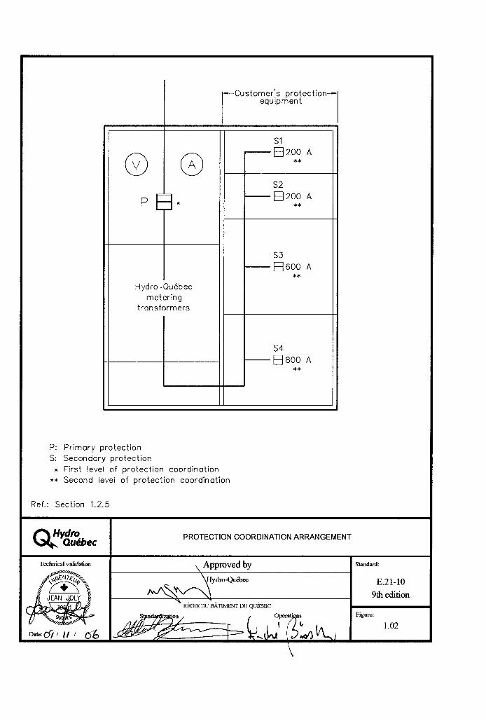
80

81

82

83

84

85

86

87

88

89

90

91

92

93

94

95

96
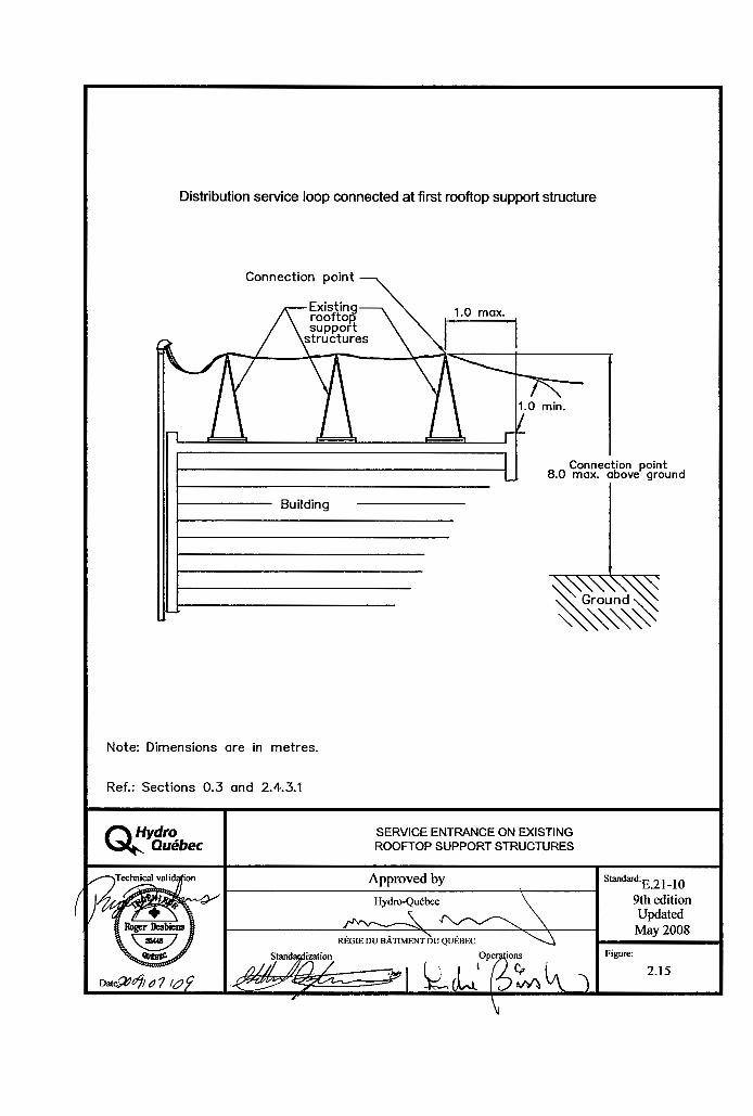
97
98

99

100

101

102

103

104

105

106

107

108

109

110

111

112

113

114

115

116

117

118

119

120

121

122

123

124
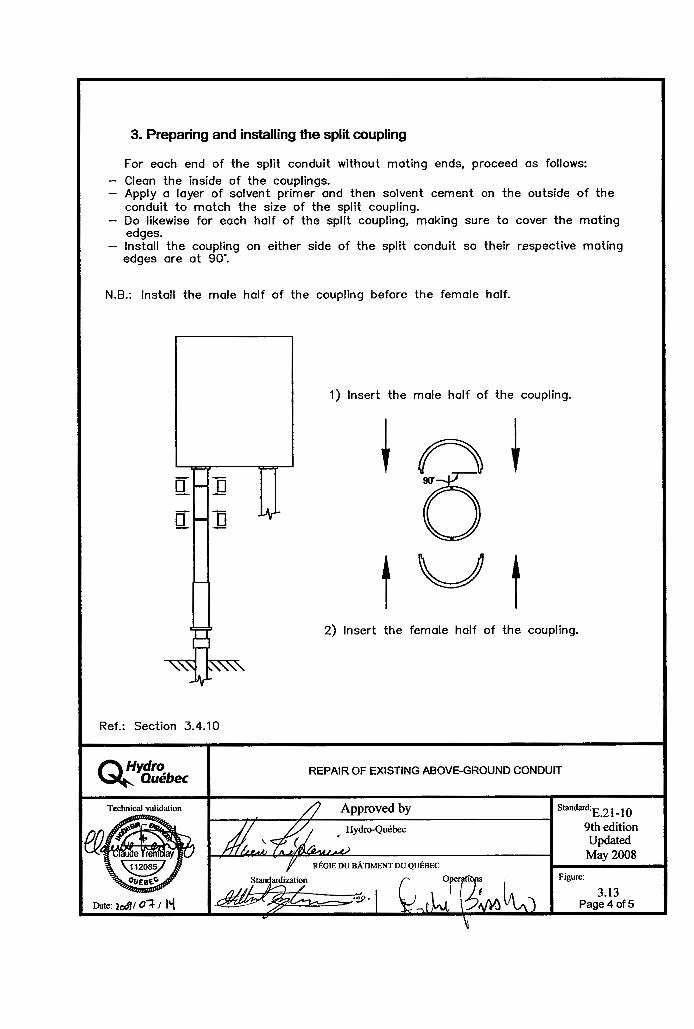
125

126

127

128

129

130

131

132

133

134

135
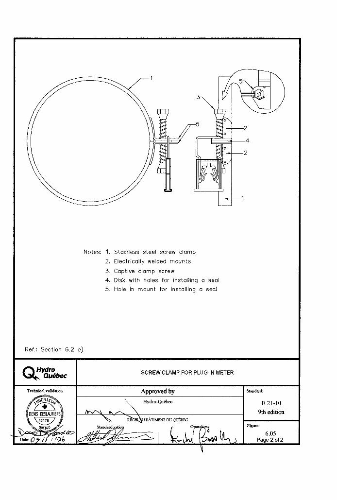
136

137

138

139

140

141

142


147


154


Tables


Tables
Table 1
Conversion table
Dimensions
Millimetres Approximate equivalent in inches
Exact millimetre equivalent of inches given
6 9 10 12.7 13 14 15 17 19 20 25 25.4 26 28 31.75 35 38 40 44 50 52 59 61 63.5 70 75 78 87 96 100 105 114 122 131 140
1/4 3/8 3/8 1/2 9/16 9/16 5/8 11/16 3/4 3/4 1 1 1 1 1/8 1 1/4 1 7/16 1 1/2 1 5/8 1 3/4 2 2 1/8 2 3/8 2 7/16 2 1/2 2 13/16 3 3 1/8 3 7/16 3 13/16 3 15/16 (4) 4 3/16 4 1/2 4 13/16 5 3/16 5 9/16
6.35 9.53 9.53 12.70 14.29 14.29 15.88 17.46 19.05 19.05 25.40 25.40 25.40 28.57 31.75 36.51 38.10 41.28 44.45 50.80 53.98 60.33 61.91 63.50 70.00 76.20 79.38 87.31 96.84 100.01 (101.60) 106.36 114.30 122.24 131.76 141.29
Note: This table only includes dimensions used in this Standard.

Tables
Table 1
Conversion table (cont.)
Dimensions
Millimetres Approximate equivalent in inches
Exact millimetre equivalent of inches given
149 150 157 166 175 180 184 190 192 200 201 210 219 227 236 245 250 254 262 300 400 450 500 600 625 685 700 750 760 800 850 900 915 975
5 7/8 5 15/16 (6) 6 3/16 6 9/16 6 15/16 7 1/8 7 1/4 7 1/2 7 9/16 7 7/8 (8) 7 15/16 8 5/16 8 5/8 8 15/16 9 5/16 9 11/16 9 7/8 (10) 10 10 3/8 11 13/16 (12) 15 3/4 (16) 17 3/4 19 11/16 23 5/8 (24) 24 5/8 27 27 9/16 29 9/16 (30) 29 15/16 31 1/2 33 1/2 35 7/16 (36) 36 1/16 38 7/16
149.23 150.81 (152.40) 157.16 166.69 176.21 180.97 184.15 190.50 192.09 200.02 (203.20) 201.61 211.14 219.08 227.01 236.54 246.06 250.82 (254.00) 254.00 263.53 300.04 (304.80) 400.05 (404.40) 450.85 500.06 600.07 (609.60) 625.48 685.80 700.08 750.88 (762.00) 760.04 800.10 850.50 900.11 (914.40) 915.99 976.31
Note: This table only includes dimensions used in this Standard.

Tables
Table 1
Conversion table (cont.)
Dimensions
Millimetres Approximate equivalent in inches
Exact millimetre equivalent of inches given
1,000 1,050 1,100 1,125 1,200 1,275 1,300 1,350 1,400 1,425 1,500 1,575 1,600 1,650 1,700 1,725 1,800 1,875 1,900 1,950 2,000 2,025 2,030 2,100 2,200 2,300 2,400 2,500 2,600 2,700 2,800 2,900 3,000
39 3/8 41 3/8 43 5/16 44 5/16 47 1/4 (48) 50 1/4 51 3/16 53 3/16 55 1/8 56 1/8 59 1/16 (60) 62 1/8 63 65 66 15/16 67 15/16 70 7/8 (72) 73 7/8 74 13/16 76 13/16 78 3/4 79 3/4 79 15/16 (80) 82 11/16 86 5/8 90 9/16 94 1/2 98 7/16 102 3/8 106 5/16 110 1/4 114 3/16 118 1/8 (120)
1,000.12 1,050.93 1,100.14 1,125.54 1,200.15 (1,219.20) 1,276.35 1,300.16 1,357.00 1,400.18 1,425.58 1,500.19 (1,524.00) 1,577.98 1,600.20 1,651.00 1,700.19 1,725.61 1,800.22 (1,828.80) 1,876.43 1,900.24 1,951.04 2,000.25 2,025.65 2,030.41 (2,032.00) 2,100.26 2,200.28 2,300.28 2,400.30 2,500.31 2,600.32 2,700.33 2,800.35 2,900.36 3,000.37 (3,048.00)
Note: This table only includes dimensions used in this Standard.

Tables
Table 2
Service voltage limits – Allowable range
Notes: Normal operating conditions – No improvements or corrective measures are required. Extreme operating conditions – Improvements or corrective measures must be planned based on an established program, but immediate action is not necessarily required.
Ref.: Section 2.6.2 and CAN3-C235-83 (C2000)
Type of lineNominal voltage(volts)
At supply point(in volts)
Extreme operating conditions
Normal operating conditions
Single-phase 120/240
Three-phase 4 conductors
120/208Y 347/600Y
Three-phase 3 conductors
600
106/212
110/190 306/530
530
110/220
112/194 318/550
550
125/250
125/216 360/625
625
127/254
127/220 367/635
635
Type of lineNominal voltage(volts)
At point of use(at load point)
(in volts)
Extreme operating conditions
Normal operating conditions
Single-phase 120/240
Three-phase 4 conductors
120/208Y 347/600Y
Three-phase 3 conductors
600
104/208
108/187 300/520
520
108/216
110/190 312/540
540
125/250
125/216 360/625
625
127/254
127/220 367/635
635

Tables
Table 3
Mechanical strength of supports and spool racks
Rated ampacity or total rated ampacity
of service box(es)
Minimum strength at attachment
point
Type of distribution service loop conductors
120/240 V Triplex, 2 AWG 347/600 V Quadruplex, 2 AWG
120/240 V Triplex, 4/0 AWG (2/0 neutral) 347/600 V Quadruplex, 4/0 AWG (2/0 neutral)
120/240 V 3 separate conductors 477 kcmil 347/600 V 4 separate conductors 477 kcmil
2,670 N (275 kg)
2,670 N (275 kg)
2,670 N (275 kg)
2,670 N (275 kg)
6,900 N (700 kg)
9,200 N (940 kg)
Ref.: Sections 2.2.7, 2.2.12 a), 2.3.3 and 4.2 b), and CAN/CSA-C22.3 No. 1
200 A or less
201 A to 400 A
401 A to 800 A

Tables
Table 4
Minimum spool rack height based on length of service loop
Length of service loop
Minimum height of spool rack above ground level**
Service loop crossing a public
thoroughfare or loading ramp
access road*
Service loop crossing a driveway
Service loop crossing a
pedestrian area
* When the spool rack cannot be installed at the specified height without guying the existing support, Hydro-Québec relocates the conductors on the pole or erects a new pole, at its expense, to allow the connection.
** This assumes that ground level is at the same elevation at both the line supply point and connection point. The spool rack must not be more than 8 m above ground level.
Heights must be increased by at least 0.61 m if telecommunications cabling is to be run beneath the distribution service loop.
Ref.: Sections 2.2.8.1, 2.2.8.3, 2.7.2.1, 2.7.2.5, 2.8, 4.2 e) and 4.2 f)
Up to 30 m (98 ft.)
Up to 25 m (82 ft.)
Up to 20 m (66 ft.)
Up to 15 m (49 ft.)
6.5 m (21.3 ft.)
6.5 m (21.3 ft.)
6.4 m (21 ft.)
5.6 m (18.4 ft.)
5.6 m (18.4 ft.)
5.6 m (18.4 ft.)
5.4 m (17.7 ft.)
4.7 m (16.4 ft.)
5.0 m (16.4 ft.)
5.0 m (16.4 ft.)
4.8 m (15.8 ft.)
4.1 m (13.5 ft.)

Tables
Table 5
Connections by the distributor over public thoroughfares
Rated ampacity or total rated ampacity of
service box(es)
Connection made
entirely by the distributor
Connection made by customer on own property
Distance Y
Distance X + Y
Up to 200 A
Over 200 A
≤ 30 m
> 30 m
≤ 30 m
> 30 m
≤ 30 m
> 30 m
> 30 m
≤ 30 m
> 30 m
> 30 m
0*
1
1**
1
1
1**
0*
1
1
1
1
1
0
0
1 or more
0
0
1 or more
* Under Section 2.2.8, the distributor in some instances supplies a pole free of charge.
** A connection over 30 m long requires erecting one or more poles and possibly one or more guy wires, depending on the configuration. Charges established under the Conditions of Electricity Service in force are then payable. For some connection configurations, erecting an additional pole to cross a public thoroughfare may be avoided after agreement with the distributor.
*** The distributor also supplies this pole when the customer wishes to install an overhead-underground service entrance.
≤ Less than or equal to
> Greater than
Ref.: Sections 2.2.8.3 a) and 2.6.2
Additional pole needed to cross public thoroughfare***
Distributor (free of charge)
Distributor (free of charge)
Customer pole
street
X
X
Legend
Width of public thoroughfareY Distance between connection point
and property lineConnection pointPower line pole
Y

Tables
Table 6
Last span of overhead service entranceThis table is based on clearances in CAN/CSA-C22.3 No. 1.
Type of lineVoltage Conductor type
Maximum length of span nearest to line
(m)
Single-phase 120 V**
Single-phase 120/240 V
Three-phase 347/600 V and 600 V
Duplex 4 NS75 (NS1)
NS75 FT1 (NSF2)
Triplex 2 NS75 (NS1)
NS75 FT1 (NSF2)
Triplex 2/0 NS75 (NS1)
NS75 FT1 (NSF2)
Triplex 4/0 NS75 (NS1)
NS75 FT1 (NSF2)
3 separate conductors No. 477 covered
Quadruplex 2 NS75 (NS1)
NS75 FT1 (NSF2)
Quadruplex 4/0 (NS1)
NS75 FT1 (NSF2)
4 separate conductors No. 477 covered
38 38
30 30
25 25
25 21
Must be guyed (max. 6 m unguyed if max. tension = 100 N or 10 kg)*
30 28
21 18
Must be guyed (max. 6 m unguyed if max. tension = 100 N or 10 kg)*
* The maximum 6-m span nearest the line must not be taut (maximum: 100 N or 10 kg).
** For public lighting only
Ref.: Sections 2.6.2, 2.7.2.5, 4.2 e) and Figure 2.17
Note: Parallel conductors are allowed provided that they are installed as specified in the Code.

Tables
Table 7
Clearance between overhead connection and building
tan = clearance (AB)
adjacent wall (AF)
Clearance (AB) = tan x adjacent wall (AF)
tan of 5o = 0.087tan of 15o = 0.267
Ref.: Section 2.7.2.2 and Figure 2.18
DistanceAF – Adjacent wall
(mm)
Clearancerequired
AB(mm)
DistanceAF – Adjacent wall
(mm)
Clearancerequired
AB(mm)
5o angle
100 200 300 400 500 600 700 800 900 1,000 1,100 1,200 1,300 1,400 1,500
9 17 26 35 44 52 61 70 78 87 96 105 114 122 131
1,600 1,700 1,800 1,900 2,000 2,100 2,200 2,300 2,400 2,500 2,600 2,700 2,800 2,900 3,000
140 149 157 166 175 184 192 201 210 219 227 236 245 254 262
3,001 3,100 or more
804830---
15o angle
B
FA
P
Line
Connection
Building

Tables
Table 8
Ladder height-to-base range
Ref.: Section 2.7.1 and Figure 2.21
Height of resting point
(mm)
Minimum horizontal distance to base
(mm)
Maximum horizontal distance to base
(mm)
3,600 3,900 4,200 4,500 4,800 5,100 5,400 5,700 6,000 6,300 6,600 6,900 7,200 7,500 7,800 8,100 8,400
900 975 1,050 1,125 1,200 1,275 1,350 1,425 1,500 1,575 1,650 1,725 1,800 1,875 1,950 2,025 2,100
1,200 1,300 1,400 1,500 1,600 1,700 1,800 1,900 2,000 2,100 2,200 2,300 2,400 2,500 2,600 2,700 2,800
HeightLadder
Horizontal distance
Resting point
Wall
Ground
min.
max.

Tables
Table 9
Junction box and pullbox characteristics
Rated ampacity or total rated ampacity of
service box(es)
Box dimensions(mm)
≤ 200 A
> 200 to 400 A
> 400 to 600 A
> 600 to 1,200 A
500
750
900
1,200
500
750
900
1,200
250
250
300
300
1
1
2
2
16
16
14
14
* If the box is installed outdoors, it must be Type 3R and have mechanisms for installing a seal.
≤ Less than or equal to
> Greater than
Ref.: Sections 3.5.3.1 and 3.5.3.2
Number of sealing
mechanisms
Gauge of metal
enclosure*
Height Width Depth

Tables
Table 10
Clearance between underground conductors and pools
Type of installation Minimum horizontal clearance (m)
Conductors with bare neutral buried
directly in soil
Conductors with a non- conductive outer jacket or
in a non-conductive conduit
Telecommunications cabling
0 to 750 V
751 to 15,000 V
15,001 to 28,000 V
1.0
1.0
3.0
6.0
1.0
1.0
1.0
2.0
Ref.: Section 3.7.5 and CSA C22.3 No. 7
Note: Voltages are line-to-line

Table 11
Transformer boxes
Rated ampacity
of box
Installation with one conductor per phase
Installation with parallel conductors
(maximum of three per phase)**
Supply voltage Supply voltage
≤ 100 A
> 100 to 200 A
> 200 to 400 A
> 400 to 600 A
> 600 A
Socket
Socket
Type A
–
–
Socket
Type A
Type B
–
–
Socket* or type A
Type A***
Type B
–
–
–
–
Type A
Type B
Type C
–
–
Type B
Type C
Type C
–
–
Type B
Type C
Type C
* Meter sockets are allowed only at 347/600 V (Section 5.5 and 5.6).
** Section 7.3.2.9 d)
*** Except for boxes dedicated to fire pumps for which a meter socket is allowed (Section 5.5)
≤ Less than or equal to
> Greater than
120/240 V 120/208 V 347/600 V 120/240 V 120/208 V 347/600V
A – Choice of transformer box type
Tables
B – Characteristics of transformer box types
Type of box
Dimensions Gauge of box metal
Gauge of plate metal
Number of bolts*
Number of sealing
mechanisms*
A**
B
C
750 x 750 x 250 mm
900 x 900 x 300 mm
1,200 x 1,200 x 300 mm
16
14
14
14
14
14
2
2
2
2
2
2
* Bolts and sealing mechanisms may be combined in the same device.
** Type-A boxes are also used as meter boxes.
Ref.: Sections 7.3.2.2 and 7.3.3.2

• Conductorsmustbebrushedbeforeconnection.
• Copperconductormustbeplacedbeneathaluminumconductor.
• Cablestoreplace:conductorsthinnerthan2AWG
• Compliantcables:1No.2ACSRneutralmessengerand2No.2Alconductors(200Aorless)
Ref.: Section 1.2.2.4
Table 12
Compression connectorsCombinations: aluminum-aluminum or aluminum-copper
Tap A
Main B
Compression tool
4 Al or 4 ACSR or 2 Al or 2 ACSR
Manufacturer Manufacturer
Insulating cover
Blackburn Homac Ilsco Kearney
10, folded in two
8, folded in two
6
4
3
2
1
1/0
2/0
3/0
4/0
250 kcmil
C5C
C5C
C5C
C5C
C5C
C7C
C7C
C7C
C7C
C7C
C7C
C7C
WR-189
WR-189
WR-189
WR-189
WR-289
WR-379
WR-379
OB-101
OB-101
OB-101
DB-202
DB-202
DB-202
HT-6
HT-6
HT-6
HT-6
HT-6
HT-8
HT-8
HT-8
HT-8
HT-2
HT-3
HT-3
506-82
506-82
506-82
506-82
506-82
508-82
508-82
508-82
508-82
502-82
503-82
503-82
4
4
4
4
4
5
5
5
5
5
5
5
2
2
2
2
2
2
2
2
2
2
2
2
O
O
O
O
O
O
O
O
O
D
D
D
Catalogue number Catalogue No. No. indents
Hydraulic 12 t
Die
ManualThomas & Betts
Distribution conductorCustomer conductor
Tables

Tables
Table 13
Insulation-piercing connectors (saline environment)Combinations: aluminum-aluminum or aluminum-copper
• Theseconnectorsmustonlybeusedinasalineenvironment.
• Cablestoreplace:Conductorsthinnerthan2AWG
• Compliantcables:1No.2ACSRneutralmessengerand2No.2Alconductors(200Aandless)
• Single-useconnector
Ref.: Sections 1.2.2.4 and 2.3.5
Customer conductor
Tap A
Distribution conductor
4 Al to 4/0 Al 2 Al to 4/0 Al
KZ3-4/0
KZ3-4/0
KZ3-4/0
KZ3-4/0
KZ3-4/0
KZ3-4/0
KZ3-4/0
KZ3-4/0
KZ4
TTD 2710 F BHQ
TTD 2710 F BHQ
TTD 2710 F BHQ
TTD 2710 F BHQ
TTD 2710 F BHQ
TTD 2710 F BHQ
TTD 2710 F BHQ
TTD 2710 F BHQ
4
3
2
1
1/0
2/0
3/0
4/0
250 kcmil
AMP SICAME
Catalogue number
Main B
Manufacturer


175
Work at the Connection Point

176
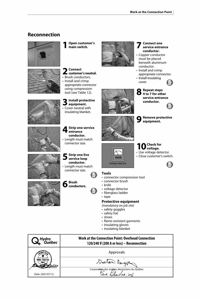
177
1 Open customer’s main switch.
2 Connect customer’s neutral.
• Brush conductors.• Install and crimp appropriate connector using compression tool (see Table 12).
3 Install protective equipment.
•Cover neutral with insulating blanket.
4 Strip one service entrance
conductor.• Length must match connector size.
5 Strip one live service loop
conductor.• Length must match connector size.
6 Brush conductors.
7 Connect one service entrance
conductor.•Copper conductor must be placed beneath aluminum conductor.• Install and crimp appropriate connector.• Install insulating cover.
8 Repeat steps 4 to 7 for other
service entrance conductor.
9 Remove protective equipment.
10 Check for voltage.
• Usevoltagedetector.•Close customer’s switch.
Reconnection
Tools• connectorcompressiontool• connectorbrush• knife• voltagedetector• fiberglassladder• tape
Protective equipment (mandatory on job site)• safetygoggles• safetyhat• shoes• flame-resistantgarments• insulatinggloves• insulatingblanket
Work at the Connection Point: Overhead Connection 120/240 V (200 A or less) – Reconnection
Approvals
Corporation des maîtres électriciens du Québec
Date: 2001/07/12
Work at the Connection Point

178
1 Open customer’s main switch.
2 Install protective equipment.
•Cover neutral and one service entrance conductor with insulating blanket.• Leave only the conductor being worked on exposed.
3 Disconnect one service
entrance phase.•Cut conductor.
4 Insulate end of service entrance
conductor.• Insulate conductor on supply and load sides with insulating tape.
5 Repeat steps 3 and 4 for
other phase.
6 Remove protective equipment.
7 Disconnect customer’s neutral.
• Cutconductor.
Disconnection
Requirements• electricalcontractor’slicence• journeymanconstructionelectrician’s certificate
Tools• cablecutter• fiberglassladder• tape
Protective equipment (mandatory on job site)• safetygoggles• safetyhat• shoes• flame-resistantgarments• insulatinggloves• insulatingblanket
Work at the Connection Point: Overhead Connection 120/240 V (200 A or less) – Disconnection
Approvals
Corporation des maîtres électriciens du Québec
Date: 2001/07/12
Work at the Connection Point

179
Reconnection (saline environment)
Requirements• electricalcontractor’slicence• journeymanconstructionelectrician’s certificate
Tools• 9/16”ratchetwrench• fiberglassladder• voltagedetector
Protective equipment (mandatory on job site)• safetygoggles• safetyhat• shoes• flame-resistantgarments• insulatinggloves• insulatingblanket
1 Open customer’s main switch.
2 Connect customer’s
neutral.• Install appropriate insulation-piercing connector (see Table 13).• Tighten until rupture nut/bolt breaks.
3 Install protective equipment.
•Cover neutral with insulating blanket.
4 Connect one service entrance
conductor.• Install appropriate insulation-piercing connector.• Tighten until rupture nut/bolt breaks.
5 Repeat Step 4 for other service
entrance conductor.
6 Remove protective equipment.
7 Check for voltage.
•Use voltage detector.•Close customer switch.
Work at the Connection Point: Overhead Connection 120/240 V (200 A or less) – Saline Environment – Reconnection
Approvals
Corporation des maîtres électriciens du Québec
Date: 2001/07/12
Work at the Connection Point

180
1 Open customer’s main switch.
2 Install protective equipment.
•Cover neutral and one service entrance conductor with insulating blanket.• Leave only conductor being worked on exposed.
3 Disconnect one service
entrance phase.•Unbolt insulation- piercing connector or cut conductor if necessary.
4 Insulate end of service entrance
conductor.• Insulate conductor on supply and load sides with insulating tape.
5 Repeat steps 3 and 4 for other
phase.
6 Remove protective equipment.
7 Disconnect customer’s neutral.
• Unboltinsulation- piercing connector or cut conductor if necessary.
Disconnection (saline environment)
Requirements• electricalcontractor’slicence• journeymanconstructionelectrician’s certificate
Tools• 9/16”ratchetwrench• cablecutter• fiberglassladder• tape
Work at the Connection Point: Overhead Connection 120/240 V (200 A or less) – Saline Environment – Disconnection
Approvals
Corporation des maîtres électriciens du Québec
Date: 2001/07/12
Protective equipment (mandatory on job site)• safetygoggles• safetyhat• shoes• flame-resistantgarments• insulatinggloves• insulatingblanket
Work at the Connection Point

181
Index

182

Index 11 Access
buildings with no basement 3.5.7connection box for flat-rate service
(compartment) 3.6.3connection point 2.7.1current transformers 7.4.4.3meter socket 6.3.6pullbox or junction box 3.5.5transformer box 7.3.2.3voltage transformers 7.4.5.2
Adapter
conduit 3.4.3, 3.4.6
Agreement with Hydro-Québec
distance between conductors and service head 2.8.1.2
location of outdoor meter sockets (ground floor) 6.3.3
separate metering equipment (different voltages) 5.8
Appurtenant structure
clearance 2.2.8.3, 2.5.2, 2.7.2.4, 3.7.5
Attachment point
mechanical strength 2.2.7, 2.2.12 a)requirements 4.2 b), Table 3
Authorization
breaking of metering equipment seals 1.2.1.1buildings with a meter in each unit 6.3.4.3electrical installation protection 7.2.1electricity generation 1.2.3inrush current 1.2.4.2new installations 1.2.2outdoor installations with five or
fewer meter sockets 6.3.1overhead-underground service entrance 2.8 d)reconnection of service entrance 1.2.2.4
Index
183

Auxiliary system
customer vault substation 7.2.2
Backup generator
location 1.2.3.1temporary supply circuits 1.2.2.6
Bolts
transformer box 7.3.2.1 e)
Building with no basement
alternative arrangements 3.5.8pullbox or junction box 3.5.7
Busbar
connection box 3.6.3metal-clad substation 7.4.4.2, 7.4.9.3 b)voltage transformers 7.4.5.1window-type transformers 7.4.4.4 d)
Bypass mechanism
meter socket 6.2 d)
Characteristics
connection box for flat-rate service 3.6.3fixed grounding points 7.4.9.3 a)junction box 3.5.3.2meter box 7.3.3.2protection 1.2.5 a)pullbox 3.5.3.1transformer box 7.3.2.2two-voltage supply 1.4.1.1
Charges
safety-related 2.8.2stipulated (service request) 1.1.4underground conduit system 3.3
Circuit breaker panel
lockable door 7.3.4.2 c)
Cleaning
cable-pulling rope 3.4.8underground conduit 3.4.7
Index
184

Clearance
appurtenant structure, stand, pool 2.2.8.3 b), 2.5.2, 2.7.2.4, 3.7.5between conductors and roof 2.2.9.1connection point 2.7.2.2distribution service loop 2.2.3, 2.2.9.2, 2.5.2, 2.7.3, 3.7.5drip loops 2.2.9.1, 2.2.9.2, 2.2.10, 2.8.1.2junction box and pullbox 3.5.5meter box 7.3.3.2 c)meter socket 6.3.6.1 b)mounting plate 7.3.2.1 d)pullbox 3.5.1service box 5.7single-phase outdoor meter 7.1.2spool rack 2.2.8.1transformer box 7.3.2.6
Demande d’alimentation et déclaration de travaux form
breaking seal (component) 1.2.1.2breaking seal (metering equipment) 1.2.1.1deadline 1.2.1.3exclusions 1.2.2.2 a)submitting 1.2.2.2 a)
Common support
mechanical strength 2.2.12 a), Table 3
Complex structures
additional service loops 1.4.1.2 b)
Conductors
120/208-V or 347/600-V supply 7.3.2.9 c)adjacent wall 2.7.2.2clearance above roof 2.2.9distance from service head 2.8.1.2falling ice 2.2.11gauge 3.8.1, 7.3.1.2gauge and number 7.3.2.9 d)identification (color coding) 7.3.2.10length at service head 2.3.1, 2.8.1.3length in junction box 3.8.2modification 6.3.4modification (more than four conductors) 2.1.2neutral for multiple secondary service boxes 6.3.7.3
Index
185

neutral in metal-clad substation 7.4.8neutral in meter socket 6.2 h)neutral in saline environment or
with tingle voltage filter 2.3.5neutral in transformer box 7.3.2.9 b)number in overhead connection 2.1.1number in underground connection 3.1.3overhead (temporary service) 4.2 b)placement in transformer box 7.3.2.9 a)PVC section 2.3.4safety requirements 2.8.2supply and installation (temporary service) 4.2 e)types 2.2.12 e)
Conduit compatibility
underground conduits 3.4.4
Conduit sealing
underground conduit 3.4.9
Conduit system
above-ground (repairing) 3.4.10sum of bends 3.7.4.3temporary service 4.2 a)underground 3.3
Conduits
adapter 3.4.6below-ground entrance 3.4.3between boxes 7.3.3.2 e)cable-pulling rope 3.4.8compatibility 3.4.4description 3.4.1entrance into building 3.4.2expansion joint 3.4.6exterior wall 3.4.5ground-wire clamp 2.3.4, 2.8.1.4inspection and cleaning 3.4.7location in building 3.5.6number and type in overhead-underground
service entrance 2.8.1.1outdoor, requirements 7.1.2.1placement on transformer box 7.3.2.8
Index
186

PVC section 2.3.4sealing 3.4.9
Connection
after disconnection 1.2.2.3by master electrician 1.2.2.4charges 1.1.4customer generation 1.2.3information required 1.1.3requirements 1.2.2.2temporary service 4to ground bar 7.4.7underground connection 3
Connection box for flat-rate service
characteristics 3.6.3connection point 3.2.1.4, 3.2.1.5definition 0.3number 3.1.4supply and installation 3.6.2use 3.6.1
Connection of equipment
compliance with standards 2.9 a)connection point 2.9.3preliminaries 2.9 b)requirements 2.9 d)safety requirements 2.9.2space on pole 2.9 c)technical requirements 2.9.1
Connection point
access 2.7.1choosing 2.4.2.3clearance 2.7.3connection box for flat-rate service 3.2.1.4equipment connection 2.9.3existing rooftop support structure 2.4.3.1handhole 3.2.1.5, 3.7.2junction box 3.2.1.3location on overhead power system 2.7.2location on underground power system 3.2.1manhole 3.2.1.6, 3.7.3
Index
187
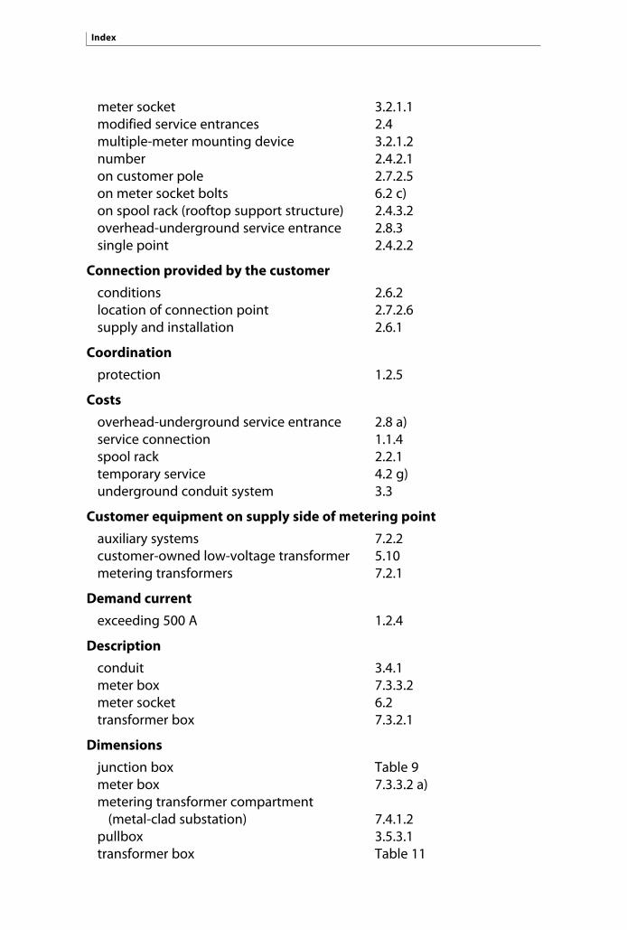
meter socket 3.2.1.1modified service entrances 2.4multiple-meter mounting device 3.2.1.2number 2.4.2.1on customer pole 2.7.2.5on meter socket bolts 6.2 c)on spool rack (rooftop support structure) 2.4.3.2overhead-underground service entrance 2.8.3single point 2.4.2.2
Connection provided by the customer
conditions 2.6.2location of connection point 2.7.2.6supply and installation 2.6.1
Coordination
protection 1.2.5
Costs
overhead-underground service entrance 2.8 a)service connection 1.1.4spool rack 2.2.1temporary service 4.2 g)underground conduit system 3.3
Customer equipment on supply side of metering point
auxiliary systems 7.2.2customer-owned low-voltage transformer 5.10metering transformers 7.2.1
Demand current
exceeding 500 A 1.2.4
Description
conduit 3.4.1meter box 7.3.3.2meter socket 6.2transformer box 7.3.2.1
Dimensions
junction box Table 9meter box 7.3.3.2 a)metering transformer compartment
(metal-clad substation) 7.4.1.2 pullbox 3.5.3.1transformer box Table 11
Index
188

Distance
between conductors and service head 2.8.1.2between junction box and floor 3.5.2.2between meter socket and ground 6.3.6.1 a)between power system and meter 4.2 c)between pullbox and floor 3.5.2.1between roof and spool rack 2.2.9.1between spool rack and service head 2.2.4between spool rack and
telecommunications wires 2.2.10between spool racks 2.2.12 b)between transformer box and service box 7.3.2.4between two spool racks 2.2.6
Distribution panel
identification 1.2.2.2 c), 5.9, 5.9.2
Distribution point
six or more meter sockets 6.3.2.1 b)
Disturbances
inrush current 1.2.4
Door
circuit breaker panel 7.3.4.2 c)clearance 7.3.2.6 b)current transformers 7.4.4.4 c)pullbox or junction box 3.5.3transformer box 7.3.2.1
Drainage
conduit entrance 3.4.2
Electrical diagram
metal-clad substation 7.4.2.1
Electricity generation
backup generator 1.2.3.1consent and requirements 1.2.3
Engraved tag
meter socket 5.9.3 b)
Exit from service head
placement of spool rack 2.2.4
Index
189

Filter
tingle voltage 2.3.5
Fire pump
additional service loop 1.4.1.2 a)
Fixed grounding point
temporary grounding 7.4.9.3
Ground bar
connection 7.4.7
Grounding
connection 7.4.7temporary 7.4.9.3
Ground-wire clamp
metal conduit 2.8.1.4pole-mounted equipment 2.9.1.4PVC section 2.3.4
Grouped supply
buildings with five or fewer meter sockets 6.3.4.1 b)definition 0.3identification 5.9.2meter socket type 6.2 a)
Grouping
building with more than one service loop 1.4.1.1meter sockets 6.3.2.1, 6.3.6.1 b)multiple voltage supply 5.8special rates 1.4.3transformer box 7.3.2.4
Guard post
clearance 6.3.6.2 b)meter protection 6.3.6.2transformer box protection 7.3.2.7
Handhole
connection point location 3.2.1.5, 3.7.2definition 0.3
Index
190

Height
120/240-V meter socket 6.3.6.1current transformers 7.4.4.4 b)inscription 2.8 g), 5.9.3 a), 5.9.3 b)meter box 7.3.3.2 c)metering transformer compartment 7.4.1.2spool rack 2.2.8transformer box 7.3.2.5voltage transformer support structures 7.4.5.3
Ice fender
smooth roof 2.2.11
Identification
conductors in transformer box 7.3.2.10electrical installation components 1.2.2.2 c), 5.9grouped supply 5.9.2meter sockets 1.2.2.2 c), 5.9.1metering centre 5.9.1 methods 5.9.3premises 1.2.2.2 b)requirements 5.9.1, 5.9.2service box 1.2.2.2 c)street address 2.8 g)transformer box 1.2.2.2 c)
Information
service contract 1.1.3
Inspection
120/240-V supply (cable-pulling rope) 3.4.8underground conduit 3.4.7
Installation
connection box 3.6.2connection provided by the customer 2.6.1current transformers 7.4.4.2distribution service loop 2.5.1, 3.7.1fixed grounding points 7.4.9.3 b)meter socket 6.1, 6.3.1, 6.3.2, 6.3.2.1,
6.3.2.2, 6.3.3, 6.3.4, 6.3.4.1, 6.3.4.3, 6.3.5, 6.4.2
metering equipment (multiple voltages) 5.8
Index
191

overhead-underground service entrance 2.8 a)pullbox or junction box 3.5.4riser conduit on exterior wall 3.4.5spool rack 2.2.1temporary overhead conductors 4.2 e)temporary supply circuits 1.2.2.6temporary underground cables 4.2 g)voltage transformers 7.4.5.1
Instrument transformer metering
customer equipment on supply side of 7.2in metal-clad substation 7.4in transformer box 7.3meter socket types 6.2 a), 6.4.1, 6.5.1minimum temperature (shelter or room) 7.0on farms 7.1.2where access constraints apply 7.1.1
Insulation
neutral conductor 2.3.5, 6.2 h)Expansion joint 3.4.6
Jaws
meter socket 6.2 g)single-phase 120/240-V installation 6.3three-phase 120/208-V installation 6.4.1three-phase 347/600-V installation 6.5.1two-phase 120/208-V installation 6.4.1
Junction box
access and clearance 3.5.5building with no basement 3.5.7characteristics 3.5.3, 3.5.3.2conductor length 3.8.2definition 0.3indoor installation 3.5.2.2 a)location of conduits 3.5.6.2number of conductors 3.1.3outdoor installation 3.5.2.2 b)supply and installation 3.5.4use 3.5.1.2
Ladder
access 2.7.1, Table 8building with no basement 3.5.7
Index
192

Length
cables in manhole 3.7.3conductors at service head 2.3.1conductors in junction box 3.8.2conductors in transformer box 7.3.2.9 a)conductors supplying protection devices 1.2.5 b)conduits (below-ground entrance) 3.4.3excess cable 4.2 e)overhead-underground conductors
at service head 2.8.1.3service mast 2.3.2underground connection 3.7.2
Limits
stress 2.6.2
Location
conduits on pullbox or junction box 3.5.6.2junction box 3.5.2.2meter box 7.3.3.2 d)meter inside building unit 6.3.4.3metering equipment 7.1multiple-meter mounting device 6.3.7.2outdoor meter socket 6.3.3overhead connection point 2.7.2overhead-underground connection point 2.8.3pullbox 3.5.2.1single-phase 120/240-V meter socket 6.3.7.1spool rack 2.2.2temporary connection 4.2 a)three-phase 120/208-V meter socket 6.4.2three-phase 347/600-V meter socket 6.5.2transformer box 7.3.2.3underground conduits 3.5.6underground connection point 3.2.1
Locking
safety precautions 7.3.4.2, 7.4.9.2service box 6.5.3
Lugs
connection 3.8.1metering in transformer box 7.3.1.2one-hole NEMA terminal 3.1.1, 3.1.2, 3.1.4, 3.2.1.4, 6.2 c)transformer box 7.3.1.2
Index
193

Manhole
connection point location 3.2.1.6, 3.7.3definition 0.3
Mechanical strength
common support 2.2.12 a)spool rack 2.2.7
Metal-clad substation
compartment size 7.4.1.2meters 7.4.3responsabilities 7.4.2standards 7.4.1.1
Meter
above meter box 7.4.3.1distance from power system 4.2 c)existing three-phase, three conductor
installation 5.6inside building units 6.3.4.3installation 2.2.2protection 6.3.6.2single-phase 120/140-V installation
(rating over 200 A) 5.3.2single-phase outdoor 7.1.2temporary cover 6.2 f)three-phase 120/208-V installation
(rating over 100 A) 5.4.2three-phase 347/600-V installation
(rating over 100 A) 5.5.2
Meter box
above 7.4.3.1characteristics 7.3.3.2placement of conduits 7.3.2.8
Meter socket
clearance 6.3.6.1definition 0.3description 6.2grouped 6.3.2.1identification 1.2.2.2 c)
Index
194

indoor installation 6.3.2, 6.3.4.1 b), 6.3.4.2, 6.3.4.3, 6.3.5
number 3.1.1, 6.3.1, 6.3.2outdoor installation 6.3.1, 6.3.2, 6.3.2.2, 6.3.3,
6.3.4.1 a) and b), 6.3.4.2position 6.3.6position (120/208 V) 6.4.2position (120/240 V) 6.3.7.1position (347/600 V) 6.5.2position (multiple secondary boxes) 6.3.7.3single-phase 120/240-V installations 6.3supply and installation 6.1temporary cover 6.2 f )three-phase 120/208-V installations 6.4three-phase 347/600-V installations 6.5
Metering
for different voltages 5.8meter room 6.3.2.1 a), 6.3.2.1 b)number of metering points allowed 1.5safety precautions 7.3.4, 7.4.9types 5.1
Metering centre
347/600 V 6.5.5definition 0.3identification 5.9.1self-contained metering 6
Metering equipment
customer equipment on supply side of 7.2definitions 0.3modification or subsequent work 1.2.2.5protection 7.3.2.7responsibilities 7.4.2shelter 7.1.1
Metering point
disturbances 1.2.4number allowed 1.5separate (case allowed) 1.4.1.2
Index
195

Metering types
instrument transformer metering 5.3.2, 5.4.2, 5.5.2self-contained metering 5.3.1, 5.4.1, 5.5.1
Mounting plate
meter box 7.3.3.2 b)terminal block 7.4.6transformer box 7.3.2.1 d)
Multiple-meter mounting device
clearance and height 6.3.6.1connection point 3.2.1.2definition 0.3installation with five or fewer meter sockets 6.3.6.1 a)location 6.3.6.2number 3.1.2outdoor 6.3.1
Number allowed
conductors in transformer box 7.3.2.9 d)connection points 2.4.2.1metering points 1.5overhead distribution service loops 1.4overhead service entrances 2.1underground service entrances 3.1
Openings
transformer box 7.3.2.1 c)
Placement
conductors in transformer box 7.3.2.9conduits on transformer box 7.3.2.8current transformers 7.4.4.4meter sockets 6.3.6spool racks 2.2.12 c)transformer box 7.3.2.4voltage transformers 7.4.5.3
Platform
clearance 2.5.2, 3.7.5transformer box 7.3.2.5
Plywood
transformer box 7.3.2.7, 7.3.3.1
Index
196

Polarity
current transformers 7.4.4.4 a)
Pool
clearance of overhead connection 2.2.3, 2.2.8.3 b), 2.5.2clearance of underground connection 3.7.5, Table 10connection point 2.7.1
Preliminaries
alternative arrangements 3.5.8connection of equipment 2.9 b)overhead-underground service entrance 2.8 c)
Protection
characteristics 1.2.5 a)coordination 1.2.5metering equipment 7.3.2.7meters 6.3.6.2, 7.3.2.7settings 1.2.5 b)
Public thoroughfare crossing
service entrance 2.6.2, 2.8 e)temporary service entrance 4.2 f)
Pullbox
access and clearance 3.5.5characteristics 3.5.3, 3.5.3.1definition 0.3location 3.5.2.1location of conduits 3.5.6.2supply and installation 3.5.4use 3.5.1.1
Pulling point
conduit 7.1.2.1conduit between boxes 7.3.3.2 e)
Readily accessible location
access to connection point 2.7.1definition 0.3
Removable front cover
meter socket 6.2 i)
Index
197

Requirements
metal-clad substation 7.4.1.1metering centre 6.5.5safety 2.8.2technical 2.9.1temporary connection 4.2.b)transformer box 7.3.2.1 g)
Responsibilities
consulting engineer 7.4.2Hydro-Québec 7.3.1.2, 7.4.2.3master electrician 1.2 , 7.3.1.1, 7.4.2.2
Responsibilities of parties
metering in metal-clad substation 7.4.2
Roof
conductor clearance 2.2.9
Rooftop support structure
definition 0.3over 8 m above ground 2.4.3.2service entrance 2.4.3up to 8 m above ground 2.4.3.1
Rope
for pulling metering conductors 7.1.2.1, 7.3.3.2 e)for pulling underground cables 3.4.8
Saline environment
boundaries 2.3.5indoor installation of meter sockets 6.3.5insulation of neutral conductor 2.3.5
Screw clamp
enclosure (installation and removal) 6.3.6.2 a)meter socket and accessories 6.2 e)
Self-contained metering
at 120/208 V 5.4, 6.4at 120/240 V 5.3, 6.3at 347/600 V 5.5at 600 V 5.6description 6.2supply and installation 6.1
Index
198
Service box
347/600 V 6.5.5clearance 5.7identification 1.2.2.2 c), 5.9, 5.9.2location 6.3.2.1, 6.5.2locking 6.5.3, 7.3.4.2 a), 7.4.9.2metering equipment choice 5.2rated ampacity 2.2.12 d)rated ampacity of 100 A or less 5.5.1secondary service boxes 6.3.7.3shelter 7.1.1
Service entrance
alternative arrangements 3.5.8conductor length 3.8.2conductor length at service head 2.3.1junction box 3.5.2.2mast 2.3.2, 2.3.3modification 2.1.2, 2.4more than one connection point 2.4.2neutral conductor 2.3.5new installation 1.2.2.1number allowed 2.1.1, 3.1.1on rooftop support structures 2.4.3one connection point 2.4.1prior requirements 1.2, 1.2.2.2reconnection (requirements) 1.2.2.4temporary service 4.2
Service entrance, individual
building with five or fewer meter sockets 6.3.4.1 a)meter socket location 6.3.7.1meter socket type 6.2 a)
Service entrance, overhead-underground
conditions for installation 2.8conductor length 2.8.1.3connection point 2.8.3definition 0.3distance between conductors and
service head 2.8.1.2metal conduit 2.8.1.4number and types of conduits 2.8.1.1safety requirements 2.8.2
Index
199

Service head
distance from conductors 2.8.1.2distance from spool rack 2.2.4
Service loop, additional
authorized cases 1.4.1.2
Service loop, overhead distribution
above adjoining structure 2.7.2.4clearance 2.2.3, 2.2.9.2, 2.5.2, 2.7.3common spool rack 2.2.6common support 2.2.12ice fender 2.2.11new service entrance 2.1.1number 1.4.1.1on adjacent wall 2.7.2.2on mast mounted on adjacent wall 2.7.2.3requirements 1.2.2supply and installation 2.5.1
Service mast
distance between spool rack and telecommunications wires 2.2.10
length 2.3.2types 2.3.3
Settings
primary protection 1.2.5 b)
Shelter
instrument transformer metering 7metering equipment 7.1.1permanent 6.3.6.2 c)protection of meters 6.3.6.2temporary connection 4.2 d)
Shop drawings
metal-clad substation 7.4.2.1
Size
conductors 7.3.1.2, 7.3.2.9 d)lugs 3.8.1service entrance (modification) 1.2.2.5
Index
200

Slope
distribution service loop 2.2.8.3 a)
Special rates
termination 1.4.3
Spool rack
clearance 2.2.3common 2.2.5, 2.2.9definition 0.3distance from service head 2.2.4distance from telecommunications wires 2.2.10distance to another spool rack 2.2.6, 2.2.12 b)for loop at higher voltage 2.2.6, 2.2.12 c)height 2.2.8location 2.2.2mechanical strength 2.2.7, Table 3special cases 2.2.8.3 a)supply and installation 2.2.1
Stand
clearance 2.5.2, 3.7.5
Substation
distribution 1.4.2 pole-mounted (definition) 0.3
Supply
conditions (temporary service) 4.2connection box for flat-rate service 3.6.2connection provided by the customer 2.6.1current transformers 7.3.1.2, 7.4.4.1customer’s handhole 3.7.2different voltages 5.8distribution service loop 2.5.1, 3.7.1emergency 1.4.1.2 a)existing 120/208 V 1.3.2existing 600 V 1.3.1existing three-phase 120/208 V 5.4fixed grounding points 7.4.9.3 b)low voltage 1.3meter box 7.3.3.2, 7.4.3.1meter sockets 6.1
Index
201

meter 7.3.1.2metering equipment 6.1, 7.3.1.2, 7.4.4.1pullbox or junction box 3.5.4secondary conductors 7.3.1.2secondary service boxes 6.3.7.3single-phase 120/240 V 5.3, 6.3spool racks 2.2.1temporary connection 4.2temporary overhead conductors 4.2 e)temporary supply circuits 1.2.2.6temporary underground cables 4.2 g)three-phase 120/208 V 6.4three-phase 347/600 V 6.5, 5.5three-phase, three-conductor 600 V 5.6two voltages 1.4.1.1voltage transformers 7.3.2.1, 7.4.5.1
Supply contract
applying 1.1.1information required 1.1.3submitting request 1.1.2
Supply point
connection point 2.8.3definition 0.3rooftop support structure 2.4.3.2 b)
Telecommunications wires
distance from spool rack 2.2.10
Temporary cover
meter socket 6.2 f)
Terminal block
Hydro-Québec responsibilities 7.4.2.3metal-clad substation 7.4.9.3 b)neutral conductor 2.3.5requirements 7.4.6
Test-terminal box
Hydro-Québec responsibilities 7.3.1.2, 7.4.2.3
Index
202

Transformer
120/208 V 1.3.2conductor length 2.8.1.3current transformers 7.4.4customer-owned low-voltage 5.10instrument transformer metering
in transformer box 7.3metering transformers 7.2.1outdoor single-phase meter 7.1.2permanent shelter 7.1.1shelter 4.2 d)voltage transformers 7.4.5
Transformer box
clearance 7.3.2.6definition 0.3description 7.3.2.1height 7.3.2.5identification for grouped supply 5.9.2identification of conductors 7.3.2.10instrument transformer metering 7.3location 7.3.2.3mounting plates 7.3.2.1 d)placement of conductors 7.3.2.9placement of conduits 7.3.2.8position 7.3.2.4protection 7.3.2.7service box over 100 A 5.4.2space for meters 7.3.3.1
Unanticipated event (force majeure)
breaking of seals 1.2.1.1definition 1.2.2.4reconnection 1.2.2.4
Underground connection
beneath or inside a building 3.7.4building with no basement 3.5.7clearance 3.7.5connection box for flat-rate service 3.1.4customer’s handhole 3.7.2junction box 3.1.3junction box location 3.5.2.2
Index
203

Index
204
location of conduits 3.5.6manhole 3.7.3meter socket 3.1.1multiple-meter mounting device 3.1.2pullbox 3.5.1.1pullbox location 3.5.2.1supply and installation 3.7.1temporary service 4.2
Voltage
available voltages 1.3multiple-voltage supply 5.8tingle voltage filter 2.3.5two-voltage supply 1.4.1.1
Zero-voltage testing
arrangement for 6.5.4, 7.3.4.1metering transformer compartment 7.4.9.1

205

Legal deposit – 3rd quarter 2009Library and Archives CanadaBibliothèque et Archives nationales du QuébecISBN 978-2-550-56215-3
Ce document est également disponible en français.
2009G1249A

Low-VoltageElectrical ServiceStandard E.21-10
L9th editionUpdated December 2008
Produced by Direction principale – Communicationsfor Vice-présidence – Réseau de distribution