low voltage distribution - alfanar...10 appearance with its new design, alfanar eletragear has...
TRANSCRIPT

LOW VOLTAGEDISTRIBUTION POWER & CONTROL
www.alfanar.com

2

Contents
1 - General Features 42 - Applications 53 - Product Portfolio 64 - Main Distribution Board (EletraGear) 8 • Technical Data 9 • Appearance 10 • Product Breakdown 11 • Admissible Current in Copper Bars 12 • Main Busbar Supports 12 • Dimensions and Possible Layouts 13 • Possible Layouts 14 - Air Circuit Breaker 14 - Molded Case Circuit Breaker 155 - Sub Distribution Board (EletraSub) 16 • Technical Data 17 • Standard Dimensions, Number of Ways and Ampere Ratinge 186 - Final Distribution Board (Eletra-LD) 20 • Technical Data 21 • Standard Dimensions, Number of Ways and Ampere Ratinge 227 - Synchronizing Panel Board 248 - Automatic Transfer Switches (ATS Panels) 26 • ATS Types 279 - Power Factor Correction Capacitors (PFC) 28 • Technical Data 2910 - Motor Control Centers (EletraGear Plus) 30 • Types of Starters 30 • Technical Data 31 • IDS Technology 32 • IDS System Features 33 • Arc Safe Vertical Bus Section 34 • Pressure Contact 34 • Arc Fault Free Contacting Device 3411 - Switch-Rack 3512 - Customer Reference 36 • New IEC Std 61439 36 • Separation Forms 37 • Ingress Protection (IP) 38 • IK Code “Mechanical Impact Test” 39 • Arc Flash Protection 40 • Anti-seismic Switchboards and Withstand for Vibration 41 • Definitions 42

4
1 - General Features
Reliability and Service Continuityalfanar products are designed to withstand the toughest environmental conditions and offer an extremely high level of reliability even under the toughest conditions.
Superior temperature performance up to 50°C without derating with alfanar ACBs and MCCBs.
Reinforced framework to guarantee increased resistance to earthquakes as per (IEC 60068-3-3:2013).
Our products offer a variety of protection levels (IP40, IP42 up to IP66) for use in a variety of applications and harsh environments such as cement works, wet areas, iron and steel industry, etc….
Flexible and User Friendly alfanar products provide years of safe, reliable operations.The mechanical structure (frame) and the main busbar systems are designed to be maintenance-free and accessible from the front.
By eliminating the need to access the equipment from the rear, our equipment can be installed virtually anywhere in a facility.
The modular design allows for easy installation, operation and maintenance and will accommodate most project specificationsandrequirements.
Safetyalfanar quality systems and solutions are developed according to relevant international standards, offering a high degree of personal and operating safety.

2 - Applicationsalfanar Low Voltage products are used for electrical power distribution and control and are generally installed downstream of transformers or generators that contain the main and distribution circuit breakers. Loads are motors, heating equipment, lighting and air-conditioning units.
Buildings, Infrastructure and Industrial:Airports, hospitals, factories, shopping malls, hotels, commercial and residential towers.
Utility: Power generation, transmission, distribution substations, water and waste water treatment plants.
Oil and Gas: Oilandgasplants,petrochemicalplantsandrefineries.

6
Eletra-LDFinal Distribution Board
Switch-Rack
3 - Product PortfolioEletraGear Main Distribution BoardATS, Synch, 2 out of 3,..

PFC Power Factor Correction
EetraSubSub Distribution Board
EletraGear PlusMotor Control Center

8
EletraGear Overview • TestedforInternalArcFaultasper(IEC-61641:2014)for100KA,300msec(ClassifiedasPSC). • Tested to withstand vibration caused by an earthquake of Richter magnitude 8 (Zone - 4), in accordance with (IEC 60068-3-3:2013). The design makes it suitable for seismic risk sites such as the western region of KSA. • RAL7035 color is standard, other colors can be provided upon request. • Neutral and earth busbars can be rated up to 100% of the main busbar. • Optimized solution with compact design provides 6300A in 800mm depth only.
Standards • IEC 61439 -1 & 2 • IEC 60529 • IEC62262 • IEC 61641 • IEC60068-3-3 • IEC60068-2-57 • IBC2006/SBC301 • SBC401 • SASO
Test Certificate • (ASTA / KEMA)
4 - Main Distribution Board (EletraGear)A switchboard is a large single panel, frame, or assembly of panels on which are accessed from front, rear or both sides. They are generally installed immediately after the power source (transformers or generators).
EletraGear is designed and tested as per the new IEC standard 61439-1,2. This panelis available up to 6300A, 100kA/ 1 sec, Form 4b.Low Voltage Switchboards are mainly used for electrical power distribution and control.

Technical Data
Enclosure Name EletraGear
Electrical Data
Rated voltage
Rated operating voltage Ue Up to 690 V
Rated insulation voltage Ui Up to 1000 V
Rated impulse withstand voltage Uimp Up to 12 kV
Overvoltage category Up to IV
Material group IIIa
Degree of pollution 3
Rated frequency 50/60 Hz
Rated current
Busbar typePure copper bars, with 99.9%conductivity
Rated current for main distribution busbar In Up to 6100 A
Conditional short circuit current Icc Up to 100 kA @ 0.2PF
Rated short-time withstand current Icw Up to 100 kA @ 1 Sec
Rated short-time withstand current Icw Up to 65 kA @ 3 Sec
Rated peak withstand current Ipk Up to 220 kA
Incoming and outgoingIncoming feeders Up to 6300 A
Distribution feeders Up to 6300 A
Arc fault Prospective short-circuit current Up to 100 kA @ 300 ms
Direct contact protectionForm of separation Up to 4b
Protection against electric shock Yes
Seismic withstand capability test and induced vibrations Yes
Ventilation Forced / Normal
MechanicalCharacteristics
Skid base height Up to 300 mm
Number of useful modules (1 module = 50mm) 43 M
Degree of protectionExternal mechanical impacts strength IK Up to IK10
External degree of protection IP Up to IP55
Steel components
Frame thickness Up to 3 mm
Sheet metal materialAluZinc steelElectrogalvanized /Stainless Steel
Surface protectionElectrostatic powder coating/ Epoxy
Standard colors RAL7035*
Panel mounting Free standing only
General
Installation environment
Ambient temperature (°C) 40*
Relative humidity max 50% at 40°C
Maximum altitude Up to 2000m*
Busbar
Busbar system 3 PH, Neutral and PE
Busbar insulating material PVC sleeving
Busbar plating material Bare / tin / silver
*For higher altitude ,ambient temperature and special colors please contact alfanar.

10
Appearance
With its new design, alfanar EletraGear has changed the concept of the bulky LV main distribution board and moved thecompetitiontothenextlevel,itismanufacturedandtestedtofulfiltheultimateneedsinallsegments.
alfanar’s ability to change the color of the switchgear according to customer requirments and applicable standards(RALandANSIseries)fortifiestheuniqueappearanceandflexibility.

Product Breakdown
alfanar switchgear is precisely sized to meet your requirements and budget. Each main distribution board provides a readytouseoptimizedsolution,designedtotheexactsizeandrequirementsforyourspecifiedfunctionalapplication.
1 Horizontal busbar 6 Roof2 Busbar connection to main horizontal busbar 7 Cable compartment3 Incomer ACB breaker 6300 Amp 8 Outgoing ACB breaker 4000 Amp4 Cable connection 9 Horizontal MCCB solution5 Frame member 10 Skid base
1
6
7
9
10
8
5
4
3
2

12
Admissible Current in Copper Bars
Main Busbar SupportsFor increased safety and to guarantee a higher level of short circuit without any side effects, EletraGear provides its design features and possible short circuit.
Short circuit level 30 kA 50 kA 65 kA 85 kA 100 kA
Busbar type Max. distance between supports
VBB 600 mm 400 mm 300 mm 250 mm 250 mm*
HBB 700 mm 650 mm 550 mm 380 mm 400 mm
*Please contact alfanar
The current available inside the horizontal copper bars, based on the number, cross-section and the outside ambient temperature is shown in the following table.
Admissible current in plated copper for 40 °C without ventilation and 50 °C with forced cooling:
Busbar Size (mm)Amp
Quantity Width Thickness1b 20 10 250
1b 30 10 400
1b 30 10 600
1b 50 10 630
1b 55 10 800
1b 60 10 1000*
1b 70 10 1000
1b 85 10 1250
2b 55 10 1600
2b 70 10 2000
2b 85 10 2500
3b 85 10 3000
3b 100 10 3200
4b 100 10 4000
4b 150 10 5000
5b 150 10 6300
*for MCC only
• All sizes mentioned in the above table are subject to manufacturer’s technical recommendation changes• In case of higher ingress protection over IP 43, forced ventilation is recommended • In case of ratings of 4000A and higher, forced ventilation is recommended• Maximum allowed size for the VBB feeding multi branch breakers = 3 x 85 x 10

Dimensions and Possible Layouts
For special dimensions upon request
Height (mm) 1600 1800 2300
Width (mm) 400 600 800 1000 1200
Depth (mm) 600 800 1000 1200
For more information please contact alfanar
EletraGear cubicles have the following representative dimensions, constructed to provide the best solution using minimumspacewithoutaffectingpowerefficiency.
Height (mm) 2150
Width (mm) 400 600 800 1000 1200
Depth (mm) 800
For more information please contact alfanar
W D
H

14
Possible Layouts
• AirCircuitBreaker
Width 600 mm 800 to 2000 AmpDepth 800 mm
Width 800 mm 2500 to 4000 AmpDepth 800 mm
Width 1200 mm 5000 to 6300 AmpDepth 800 mm

•MoldedCaseCircuitBreakerEletraGear type tested MCCB panel boards are designed for easy handling and quick, simple installation.
The compact MCCB design provides a maximum cabling area within the enclosure with removable top and bottom gland plates for easier installation and cable entry.
Form 3 / 4 Form 1 / 2Width 1000 mm 800 mm
Depth 800 mm 800 mm
Basedonthemodularconfigurationofeachsolution,variousarrangementsareavailableaccordingtothesizeand polarity: • Up to form 4b in width 1000• Up to 11 × 125 or 250 AF alfanar MCCBs 3P can be placed in one cubical for form 3 / 4• Up to 24 × 125 or 250 AF alfanar MCCBs 3P can be placed in one cubical for form 1 / 2

16
The EletraSub Distribution Board is is a component of an electricity supply system which divides an electrical power feed into subsidiary circuits while providing a protective fuse or CB for each circuit.
alfanar Sub Main Distribution Board (EletraSub) serves as a complete solution for the distribution of power and is available up to 630A. The design provides completeflexibilityatthetimeofinstallation,complying with IEC 61439-1,2.
EletraSub Overview • EletraSub is used in a variety of sectors such as utilities and co-generation, pharmaceutical factories, generator manufacturers, critical power plants, data centers and in the oil and gas industry.
• Easy interchangeability of components
• Wall mounted and free standing designs
• Available in 2/14 way (3Pole) to 6/42 way (1 Pole) outgoing MCCB’s
• Enclosure Protection Class up to IP66
• Bare Copper / tin plated / silver plated / PVC sleeved copper busbars
• Available in stainless steel enclosures for outdoor applications
• Neutral and earth busbars can be rated up to 100% of the main busbar
• Internal separation up to Form-3a
5 - Sub Distribution Board (EletraSub)
Standards • IEC 61439 -1 & 2 • IEC 60529 • IEC62262 • IEC 61641 • IEC60068-3-3 • IEC60068-2-57 • IBC2006/SBC301 • SBC401 • SASO
Test Certificate • (ASTA /UL)

Technical Data
Enclosure Name EletraSub
Electrical Data
Rated voltages
Rated operating voltage Ue Up to 690 V
Rated insulation voltage Ui Up to 800V
Rated impulse withstand voltage Uimp Up to 8 kV
Overvoltage category Up to IV
Material group IIIa
Degree of pollution 3
Rated frequency 50/60 Hz
Rated current
Busbar typePure copper bars, with 99.9%conductivity
Rated current for Distribution Busbar In Up to 630 A
Conditional short circuit current Icc 50 kA @ 0.25PF
Rated short-time withstand current Icw 50 kA @ 1 Sec
Rated peak withstand current Ipk 105 kA
Incoming and outgoingIncoming feeders Up to 630 A
Distribution feeders Up to 250 A
Direct contact protectionForm of separation Up to 3a
Protection against electric shock Yes
Ventilation Normal
MechanicalCharacteristics
Recommended depth 225 mm
Skid base height 50 mm
Number of ways Up to 14
External degree of protection IP Up to IP66
Steel componentsSheet metal material
AluZinc steelElectrogalvanized /Stainless Steel
Sheet metal thickness Up to 2 mm
Surface protectionElectrostatic powder coating/ Epoxy
Standard colors RAL7035*
Panel mountingWall mounted and free standing
Mechanical impact IK10
General
Installation environment
Ambient temperature (°C) 40*
Relative humidity max 50% at 40°C
Maximum altitude Up to 2000m*
Busbar
Busbar system 3 PH, Neutral and PE
Busbar insulating material PVC sleeving
Busbar plating material Bare / tin / silver
* For higher altitude, ambient temperature and special colors please contact alfanar.

18
Standard Dimensions, Number of Ways and Ampere Rating
EletraSub Dimensions
Incoming Details Outgoing Details Dimensions
Pan assembly No of Poles No. of Ways H (mm) W (mm) D (mm)
MCCB(125A/160A/ 250A/400A /630A)*
MCCB (125A/160A/250A)
SPN
6 900 800 225
12 900 800 225
18 900 800 225
24 1100 800 225
30 1100 800 225
36 1300 800 225
42 1300 800 225
*For 400A/630A Extension box kit should be added.
Incoming Details Outgoing Details Dimensions
Pan assembly No of Poles No. of Ways H (mm) W (mm) D (mm)
MCCB (125A/160A/250A/400A/630A)*
MCCB (125A/160A/250A)
TPN
2 900 800 225
4 900 800 225
6 900 800 225
8 1100 800 225
10 1100 800 225
12 1300 800 225
14 1300 800 225
*For 400A/630A Extension box kit should be added.
W D
H

EletraSub Accessories
Top Blank Extension box kit
Incoming Details Dimensions
H (mm) W (mm) D (mm)
(400A/630A) 150 800 225
Optional (125A/160A/250A ) 150 800 225
Bottom Blank Extension box kit
Incoming Details Dimensions
H (mm) W (mm) D (mm)
(400A/630A) 150 800 225
Optional (125A/160A/250A ) 150 800 225
Top Metering Extension box kit
Incoming Details Dimensions
H (mm) W (mm) D (mm)
Outdoor Metering Box 200` 800 225
Side Blank Extension box kit
Incoming Details Dimensions
H (mm) W (mm) D (mm)
Optional Side Blank Box
900 300 225
1100 300 225
1300 300 225

20
6 - Final Distribution Board (Eletra-LD) alfanarfinaldistributionboard(Eletra-LD) is designed to be a safe and reliable switching device for the end user where the most important part in the network is human protection.
Eletra-LDboardprovidesthesafestsolutionforthefinalloadinresidential,commercialandindustrialpremises.
Eletra-LD Overview • Easy interchangeability of components • Internal separation up to form 3a • Rated short-time withstand current (Icw) per 0.25s up to 25 kA • Peak withstand current Ipk 52.5 KA • Ingress protection up to IP66 • Flexibility to provide up to 60 ways
Standards • IEC 61439 -1 & 3 • IEC 60529 • IEC62262 • IEC 61641 • IEC60068-3-3 • IEC60068-2-57 • IBC2006/SBC301 • SBC401 • SASO
Test Certificate • (DEKRA/ASTA/KEMA )

Technical Data
Enclosure Name Eletra-LD
Electrical Data
Rated voltages
Rated operating voltage Ue 415 V
Rated insulation voltage Ui 500 V
Rated impulse withstand voltage Uimp Up to 4 kV
Overvoltage category Up to IV
Material group IIIa
Degree of pollution 3
Rated frequency 50/60 Hz
Rated current
Busbar typePure Copper Bars, with 99.9%conductivity
Rated current for Distribution Busbar In Up to 250 A
Rated diversity factor (RFD) 1
Conditional short circuit current Icc 18 KA
Rated short-time withstand current Icw 25 kA @ 0.25 Sec
Rated peak withstand current Ipk Up to 52,5 kA
Incoming and outgoingIncoming feeders Up to 250 A
Distribution feeders Up to 63 A
Direct contact protectionForm of separation Up to 3a
Protection against electric shock Yes
Ventilation Normal
MechanicalCharacteristics
Number of ways Up to 54
Degree of protectionExternal mechanical impacts strength IK IK08
External degree of protection IP Up to IP66
Steel ComponentSheet metal material
AluZinc steelElectrogalvanized /Stainless Steel
Sheet metal thickness Up to 2 mm
Surface protectionElectrostatic powder coating/ Epoxy
Standard colors RAL7035*
Panel mountingFree standing and wall mounting
General
Installation environment
Ambient temperature (°C) 40*
Relative humidity max 50% at 40°C
Maximum altitude Up to 2000m*
Busbar
Busbar system 3 PH, Neutral and PE
Busbar insulating material PVC sleeving
Busbar plating material Bare / tin / Silver
*For higher altitude ,ambient temperature and special colors please contact alfanar.

22
Standard Dimensions, Number of Ways and Ampere Rating
Eletra-LD Outdoor up to 250 A
Number of Ways H (mm) W (mm) D (mm)12 Way 600 400 16018 Way 700 400 16024 Way 700 400 16030 Way 800 400 16036 Way 800 400 16042 Way 900 400 16048 Way 900 400 16054 Way 1000 400 160
For more cutter space, 425 mm width is available.
Eletra-LD Indoor up to 250 A
Number of Ways H (mm) W (mm) D (mm)12 Way 600 400 14018 Way 650 400 14024 Way 700 400 14030 Way 750 400 14036 Way 800 400 14042 Way 850 400 14048 Way 900 400 14054 Way 950 400 140
For more cutter space, 425 mm width is available.
W D
H


24
7 - Synchronizing Panel Boardalfanar’s EletraGear Synchronizing Panels supply a large amount of power by using multiple generators working in parallel on load sharing.
These panels function both manually and with an automatic synchronizing function for one or more generators or breakers. They are widely used in synchronizing generators and offering multiplex solutions.
Our high quality range of EletraGear synchronizing panels are available with capacities that reach 12000 A, and are fabricated using high quality electrical components including copper busbar, insulation, wires/cable, PVC channels, transformers, meters and switches.

• Rated insulation voltage 1000V• Main busbars rated up to 12,000A• Protection Class up to IP55• Ambient temperature up to 40 °C• Silver / tin plated / PVC sleeved copper busbars• RAL 7035 color as standard, other colors on request• Accessible from front / rear• Cable/bus duct entry from top or bottom, with removable gland plates• Type tested in accordance with IEC 61439 -1 & 2 standard for increased safety
* For higher ambient temperature please contact alfanar
In an alternating current electric power system, synchronization is the process of matching the speed and frequency of a generator or other source to a running network. An AC generator cannot deliver power to an electrical grid unless it is running at the same frequency as the network.
M Q1ACB, 3P2000AT2000AF
1
2
F1ACB, 3P
1
2
RATED MAIN BUS 6300A (S.C.LEVEL 100KA)
F2ACB, 3P3200AT3200AF
1
2
*CT1-*CT34000/5A
R Y B
DM
*CT1-*CT34000/5A
R Y B
DM
3200AT3200AF
M Q2ACB, 3P2000AT2000AF
1
2
F3ACB, 3P3200AT3200AF
1
2
*CT1-*CT34000/5A
R Y B
DM
M Q3ACB, 3P2000AT2000AF
1
2
M Q4ACB, 3P2000AT2000AF
1
2
4 cable 630 per phase and 2 cable 630 for neutral 4 cable 630 per phase and 2 cable 630 for neutral 4 cable 630 per phase and 2 cable 630 for neutral
*FU1-*FU41P,2A
*FU1-*FU41P,2A
*FU1-*FU41P,2A
2CB23P,MCB
6AT63AF
1CB23P,MCB
6AT63AF
3CB23P,MCB
6AT63AF
4CB23P,MCB
6AT63AF
1CB1
3P,MCB6AT
63AF
1CT1-1CT3,1CTN2000/5A
1B11Y11R12CB1
3P,MCB6AT63AF
2B12Y12R13CB1
3P,MCB6AT
63AF
3B13Y13R14CB1
3P,MCB6AT
63AF
4B14Y14R1
1IG-NT1 2IG-NT12CT1-2CT3,2CTN2000/5A
3IG-NT13CT1-3CT3,3CTN2000/5A
4IG-NT14CT1-4CT3,4CTN2000/5A
INCOMER-1GEN. SET NO. 1
400/230VAC, 3Ph. 4W, 60Hz
4 cable 300 per phase and 4 cable 300 for neutral
G1
INCOMER-2GEN. SET NO. 2
400/230VAC, 3Ph. 4W, 60Hz
INCOMER-3GEN. SET NO. 3
400/230VAC, 3Ph. 4W, 60Hz
G2
4 cable 300 per phase and 4 cable 300 for neutral
G3
4 cable 300 per phase and 4 cable 300 for neutral
INCOMER-4GEN. SET NO. 4
400/230VAC, 3Ph. 4W, 60Hz
G4
4 cable 300 per phase and 4 cable 300 for neutral

26
alfanar’s EletraGear Automatic Transfer Switches (ATS Panels) provide a solution that can handle transfer of critical loads to emergency sources with reliability. They ensure the continuity of electric supply to an installation with minimum interruption by making an automatic changeover from normal supply to emergency supply.
8 - Automatic Transfer Switches (ATS Panels)
Automatic transfer switches are used to automatically change over from the main electrical supply to stand-by generators or generate on failure of the main supply.
When the main supply is restored, the system automatically changes back and stops the generator.
The stand-by generator will eventually be shut down after a short cooling down period.
• Rated insulation voltage 1000V• Busbar short-circuit withstand capacity up to 100KA for 1 sec
• Main busbars rated up to 6300A• Neutral and earth busbars rated up to 100% of the main busbar

ATS Type
1. Change-over SwitchLogic table
Condition Q1 Q2Incomer -1 & 2 Healthy 1 0
Incomer -1 Fail 0 1Incomer -2 Fail 1 0
2. Breaker Type Logic table
Condition Q1 Q2Incomer -1 & 2 Healthy 1 0
Incomer -1 Fail 0 1Incomer -2 Fail 1 0
3. Parallel Operation Logic table
Condition Q1 Q2 BCIncomer -1 & 2
Healthy 1 1 0
Incomer -1 Fail 0 1 1Incomer -2 Fail 1 0 1Manual parallel
operation 1 1 1
4. Bypass Breakers Logic table
MODE Q1 Q2 QB1 QB2Off Mode 0 0 0 0
Normal (Q1) 1 0 0 0Emergency ( Q2) 0 1 0 0
Bypass (QB1) 0 0 1 0Bypass (QB2) 0 0 0 1
TO LOAD
MECHANICAL & ELECTRICAL INTERLOCK
RATED MAIN BUS 6300A (S.C.LEVEL 100KA)
M Q1
6300AT6300AF
1
2
R Y B
V
A1
FU1-FU32A
1 2
A2 A3
CT1-CT36300/5A
0-6300A
0-500VVS
Q2
6300AT6300AF
1
2
INCOMER-2EMERGENCY SUPPLY
400/230VAC, 3Ph. 4W, 60Hz
G1
INCOMER-1NORMAL SUPPLY
400/230VAC, 3Ph. 4W, 60Hz
TO LOAD
MECHANICAL & ELECTRICAL INTERLOCK
RATED MAIN BUS 6300A (S.C.LEVEL 100KA)
M MQ1ACB, 3P6300AT6300AF
1
2
R Y B
V
A1
FU1-FU32A
1 2
A2 A3
CT1-CT36300/5A
0-6300A
0-500VVS
Q2ACB, 3P6300AT6300AF
1
2
INCOMER-2EMERGENCY SUPPLY
400/230VAC, 3Ph. 4W, 60Hz
G1
INCOMER-1NORMAL SUPPLY
400/230VAC, 3Ph. 4W, 60Hz
TO LOAD
MECHANICAL & ELECTRICAL INTERLOCK
RATED MAIN BUS 6300A (S.C.LEVEL 100KA)
M MQ1ACB, 3P6300AT6300AF
1
2
Q2ACB, 3P6300AT6300AF
1
2
INCOMER-2EMERGENCY SUPPLY
400/230VAC, 3Ph. 4W, 60Hz
INCOMER-1NORMAL SUPPLY
400/230VAC, 3Ph. 4W, 60Hz
TO LOAD
2
BCACB, 3P6300AT6300AF
M
INCOMER-2EMERGENCY SUPPLY
400/230VAC, 3Ph. 4W, 60Hz
G1
INCOMER-1NORMAL SUPPLY
400/230VAC, 3Ph. 4W, 60Hz
TO LOAD
RATED MAIN BUS 6300A (S.C.LEVEL 100KA)
ELECTRIC INTERLOCKELECTRIC INTERLOCK
ELECTRICAL & MECHANICAL INTERLOCK
6300/5ACT1-CT3
ACB, 3PQ2
M
FU1-FU4
DM
YR B
6300AF6300ATACB, 3P
Q1 M
6300AT6300AF
6300AF6300ATACB, 3P
QBC1ACB, 3PQBC2
6300AT6300AF
M M
ELECTRICAL & MECHANICAL INTERLOCK

28
9 - Power Factor Correction Capacitors (PFC)alfanar power factor correction panel is used to bring the power factor of an AC power circuit closer to 1 by supplyingreactive power of the opposite sign, adding capacitors that cancel the inductive effects of the load, which reduces transmission losses and improves voltage regulation at the load.
Correction may be applied by a utility to improve the stability andefficiencyofthetransmissionnetwork.Individualelectrical customers who are charged by their utility for low power factor may install correction equipment to reduce those costs.

Technical Data
Enclosure Name EletraGear
Standards
IEC 61921 Power Capacitors Low-Voltage Power Factor Correction Banks- Edition 2 2017-06
Apparatus Reactive power Qn 600 KVAr
Electrical Data
Rated voltages
Rated voltage Ue 440 VRated insulation voltage Ui 800 VRated impulse withstand voltage Uimp Up to 6 kV Degree of pollution 3Rated frequency Up to 60 Hz
Rated current
Capacitance tolerance *-5%, +10%Connection type Three-phaseRated current for main distribution busbar In Up to 1600 ARated diversity factor (RFD) 1Conditional short circuit current Icc 50 kARated short-time withstand current Icw 50 kA @ 1 SecRated peak withstand current Ipk Up to 105 kAOverload protection 1.5 InMaximum permissible over voltage 1.1 x Un
PFC typeFixed YesAutomatic Yes
Head circuit breaker protection
Without circuit breaker YesWith circuit breaker Yes
StepsNumbers Up to 12Capacitors type Dry type capacitorsContactors Switching
ReactorsDetuned 5.67%Detuned 7%
Direct contact protectionForm of separation 1 Up to 2aProtection against electric shock Yes
Temperature controlAutomatic power factor controller
Ventilation Forced
Mechanical Characteristics
Degree of protectionExternal mechanical impacts strength IK Up to IK10External degree of protection IP Up to IP54
Steel componentsFrame material AluZinc steel / EGSFrame thickness Up to 3 mmSheet metal material AluZinc steel / EGS
Surface protection Electrostatic powder coatingStandard colors RAL7035*Panel mounting Free standing
General
Installation environment Ambient temperature (°C) 40*Relative humidity max 50% at 40°CMaximum altitude ≤ 2000 m*
BusbarBusbar system 3*PH, Neutral and PE
Busbar insulating material Bare / tin / silver / sleeving
*For higher altitude ,ambient temp and special colors please contact alfanar.

30
The Motor Control Center is a combination of motor starters, power feeders and interlocking relays in a modular enclosure.alfanar Controlgear (EletraGear Plus) is a compact solution allowing for better control, design and safe electrical system with its most advanced technology for drawer units “IDS system”.
10 - Motor Control Centers (EletraGear Plus)
EletraGear Plus Overview • New compact drawout motor starter solution tested, (IDS German technology) • TestedforInternalArcFaultasperIEC-61641for100KA,300m.sec(ClassifiedasPSC) • Tested to withstand vibration caused by an earthquake of magnitude 8 on Richter scale, in accordance with IEC 60068-3-3, making EletraGear Plus design extremely suitable for sites with seismic risk • Fullycompartmentalized(fixed/drawout)designconformingtoformofseparationForm-4B • RAL7035 color is the standard, other colors can be provided upon request • Neutral and earth busbars can be rated up to 100% of the main busbar • Can be interfaced with the Building Management System (BMS) for monitoring and controlling the loads • Number of motor starter draw our module up to 20 (75mm) or up to 10 (150mm)
Standards • IEC 61439 -1 & 2 • IEC 60529 • IEC62262 • IEC 61641 • IEC60068-3-3 • IEC60068-2-57 • IBC2006/SBC301 • SBC401 • SASO
Test Certificate • (ASTA / KEMA)
Types of StarterDraw-out Module Fixed Module • Direct On-line • Direct On-line • Star/Delta • Auto Transformer • Star/Delta • Soft Starter Unit • Variable Speed Drive • Feeder

Technical Data
Enclosure Name EletraGear Plus
Electrical Data
Rated voltage
Rated operating voltage Ue Up to 690 VRated insulation voltage Ui Up to 1000 VRated impulse withstand voltage Uimp Up to 12 kVOvervoltage category Up to IV Material group IIIaDegree of pollution 3Rated frequency 50/60 Hz
Rated current
Busbar typePure copper bars, with 99.9%conductivity
Rated current for main distribution busbar In Up to 6100 ARated short-time withstand current Icw (1@Sec)
Up to 100 kA
Rated short-time withstand current Icw (3@Sec)
Up to 65 kA
Rated peak withstand current Ipk Up to 220 kARated current for dropper distribution in draw-out solution
Up to 1000 A
Conditional short circuit current Icc 100 kA @ 0.2PF
Incoming and outgoing
Incoming feeders Up to 6300 ADistribution feeders Up to 6300 A
Motor feeders250 A (110 KW@DOL or 45KW@SD)
Arc fault containment Prospective short-circuit current Up to 100 kA @ 300 ms
Direct contact protectionForm of separation Up to 4b Protection against electric shock Yes
Seismic withstand capability test and induced vibrations YesVentilation Forced / NormalNumber of drawer per section Up to 20
Degree of protectionExternal mechanical impacts strength IK Up to IK10External degree of protection IP IP55
Steel components
Frame thickness Up to 3 mm
Sheet metal materialAluZinc steelElectrogalvanized /Stainless Steel
Surface protectionElectrostatic powder coating/ Epoxy
Standard colors RAL7035*Panel mounting Free standing only
General
Installation environment Ambient temperature (°C) 40*Relative humidity max 50% at 40°CMaximum altitude Up to 2000m*
BusbarBusbar system 3 PH, Neutral and PEBusbar insulating material PVC sleevingBusbar plating material Bare / tin / silver
*For higher altitude, ambient temperature and special colors please contact alfanar

32
Forhumansafety,mostindustrialcompanieshavedefinedtheoperationoftheirelectricalswitchgearsintothreemajorlines to avoid accidents by the hazard potential of electrical energy:
Third line Regulation Using special cloth and following the electrical safety rules
Second Line Limitation Additional mechanical measures
First Line Prevention Measures of encapsulation of parts which are live (contacting device)
IDS Technology (Draw-out solution)
Heavy industry production plants have the enormous potential of electrical energy failures, it is important to ensure safe energy distribution and avoid even the smallest failures which could cause widespread damage.
To solve this potentially serious problem and reduce the risk of electrical failure, alfanar has developed EletraGear Plus, a new safety philosophy that uses modular switchboard systems in draw-out technologytoproducethemostefficientcontactingdevice ever designed.
The innovative safety feature is the contacting device. Thefingercontactsandthepressurecontactsusedifferent methods to reduce and eliminate the undesired effects of magnetic forces by reinforcing the contacting pressure.
For more technical information & featuresscan QR code

• Contacting device, vertical bus section and power plug form a hermetic encapsulation, creating an Arc fault-free zone.
• Vertical bus section is completely insulated from phase to phase as well as from phase to earth to reduce the risk of an internal Arc fault.
• Vertical bus section insulation is strong enough to prevent movement of the verticalbusbarswhichcouldinfluencethecontactingpressureoftheplugsystem.
• Contacting device is constructed to avoid any loss in contacting pressure during a short circuit.
• Movingthedrawerto“operatingposition”or“testingposition”willnotinfluencetheprotectiondegree of the switchgear.
• Movingtooperatingpositionispossiblewhilethewholepowercablingremainsfixed.
• The auto cleaning feature of the contacting device makes it maintenance free.
• The construction of the contacting device and its dimensions reinforce the contacting pressure during a short circuit.
• Each power contact is insulated between other contacts and against earth.
• Thecontactingdeviceisfreefrommechanicaltoleranceswhichcouldinfluencethecontactingpressure.
• All power contacts and control plugs are concealed behind the drawer frame.
IDS System Features:

34
Innovative Pressure Contact• The pressure contact within the contacting module is developed to reinforce the contacting pressure in case of a short circuit, “instead of pushing out effect forthetraditionalfingerscontactsduringshortcircuit”.
• The contact surface has an auto cleaning feature that uses the rotation motion of the dust and sand, an advantage over traditional finger contacts inserted in joints which require continual cleaning.
• The special outline of the internal copper-layer increases the contacting-pressure.
Arc Fault Free Contacting DeviceThe movable and switchable contacting modules form together with the vertical bus section insulators of the busbar module and the outgoing plug (outgoing module) to create an arc fault free zone.
• Any change of drawer modules can be rearranged while voltage is live.• Accreditedtestinglaboratorieshavecertifiedthebus duct as “arc safe”.
• The vertical bus section is completely insulated from phase to phase.• The “Automatic Shutter” is mechanically interlocked, and can additionally be padlocked.
Arc Safe Vertical Bus Section
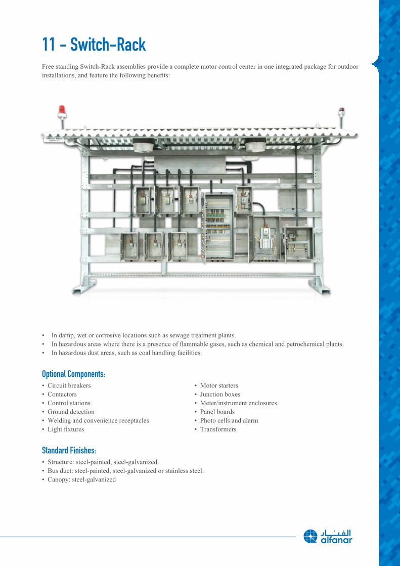
11 - Switch-RackFree standing Switch-Rack assemblies provide a complete motor control center in one integrated package for outdoor installations,andfeaturethefollowingbenefits:
• In damp, wet or corrosive locations such as sewage treatment plants.• Inhazardousareaswherethereisapresenceofflammablegases,suchaschemicalandpetrochemicalplants.• In hazardous dust areas, such as coal handling facilities.
Optional Components:• Circuit breakers • Motor starters • Contactors • Junction boxes • Control stations • Meter/instrument enclosures • Ground detection • Panel boards • Welding and convenience receptacles • Photo cells and alarm• Lightfixtures • Transformers
Standard Finishes: • Structure: steel-painted, steel-galvanized. • Bus duct: steel-painted, steel-galvanized or stainless steel. • Canopy: steel-galvanized
36
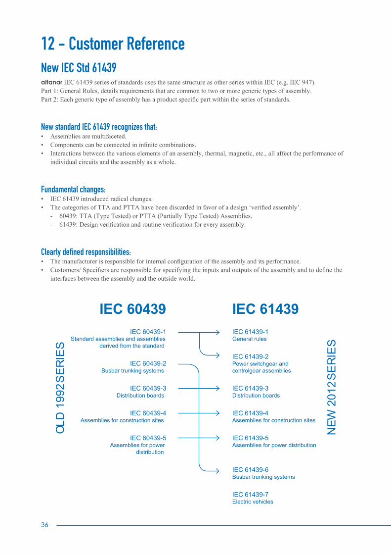
12 - Customer ReferenceNew IEC Std 61439alfanar IEC 61439 series of standards uses the same structure as other series within IEC (e.g. IEC 947).Part 1: General Rules, details requirements that are common to two or more generic types of assembly.Part2:Eachgenerictypeofassemblyhasaproductspecificpartwithintheseriesofstandards.
New standard IEC 61439 recognizes that:• Assemblies are multifaceted.• Componentscanbeconnectedininfinitecombinations.• Interactions between the various elements of an assembly, thermal, magnetic, etc., all affect the performance of individual circuits and the assembly as a whole.
Fundamental changes:• IEC 61439 introduced radical changes.• ThecategoriesofTTAandPTTAhavebeendiscardedinfavorofadesign‘verifiedassembly’. - 60439: TTA (Type Tested) or PTTA (Partially Type Tested) Assemblies. - 61439:Designverificationandroutineverificationforeveryassembly.
Clearly defined responsibilities: • Themanufacturerisresponsibleforinternalconfigurationoftheassemblyanditsperformance.• Customers/Specifiersareresponsibleforspecifyingtheinputsandoutputsoftheassemblyandtodefinethe interfaces between the assembly and the outside world.
IEC 60439IEC 60439-1
Standard assemblies and assemblies derived from the standard
IEC 60439-2 Busbar trunking systems
IEC 60439-3 Distribution boards
IEC 60439-4 Assemblies for construction sites
IEC 60439-5 Assemblies for power
distribution
OLD
199
2 SE
RIE
S
IEC 61439IEC 61439-1 General rules
IEC 61439-2 Power switchgear and controlgear assemblies
IEC 61439-3 Distribution boards
IEC 61439-4 Assemblies for construction sites
IEC 61439-5 Assemblies for power distribution
IEC 61439-6 Busbar trunking systems
IEC 61439-7 Electric vehicles
NEW
201
2 SE
RIE
S

Technical Data
Form IEC Standard Definition Specific Recommendations1 No Internal separation Protection over busbar for customer safety2a Separation of busbars from the functional units Terminals not separated from busbars2b Separation of busbars from the functional units Terminals separated from busbars
3aSeparation of busbars from the functional units and of all functional units from each other
Terminals not separated from busbars
3bSeparation of busbars from the functional units and of all functional units from each other
Terminals separated from busbars
4aSeparation of busbars from the functional units and of all functional units from each other, also separation of terminals from any functional unit
Terminals in the same compartment as associated functional units
4bSeparation of busbars from the functional units and of all functional units from each other, also separation of terminals from any functional unit
Terminals are not in the same compartment as the associated functional units
Separation Forms
Form 1 Form 2a Form 2b Form 3a
Form 3b Form 4a Form 4b
Busbar
Separation

38
Ingress Protection (IP)
Standard IEC 60529 (February 2001) indicates the degree of protection provided by electrical equipment enclosures against accidental direct contact with live parts and against the ingress of solid foreign objects or water.
The IP code comprises 2 characteristic numerals and may include an additional letter when the actual protection of personsagainstdirectcontactwithlivepartsisbetterthanthatindicatedbythefirstnumeral.
Thefirstnumeralcharacterizestheprotectionoftheequipmentagainstpenetrationofsolidobjectsandtheprotectionofpeople. The second numeral characterizes the protection of the equipment against penetration of water with harmful effects.
Protection Against Solid Bodies Data TableProtection Against Liquids Data Table Level
Protected Against Access To Hazardous
Parts WithProtection of Equipment Protection of Persons
0 Tests Non-protected Non-protected 0 Tests Non-protected
1ø 50mm
Protected against the penetration of solid objects having a diameter greater than or equal to50 mm
Protected against direct contact with the back of the hand (accidental contacts).
1Protected against vertical dripping water, (condensa-tion).
A With the back of the hand.
2ø 12.5mm
Protected against the penetration of solid objects having a diameter greater than or equal to12.5 mm.
Protected against direct finger con-tact.
2Protected against dripping water at an angle of up to 15°.
B With the finger.
3ø 2.5mm
Protected against the penetration of solid objects having a diameter greater than or equal to2.5 mm.
Protected against direct contact with a Ø 2.5 mm tool.
3Protected against rain at an angle of up to 60°.
C With a ø 2.5 mm tool.
4ø 1mm
Protected against the penetration of solid objects having a diameter greater than or equal to1 mm.
Protected against direct contact with a Ø 1 mm wire.
4Protected against splashing water in all directions.
D With a ø 1 mm tool.
5Dust protected (no harmful deposits).
Protected against direct contact with a Ø 1 mm wire.
5Protected against water jets in all directions.
6Dust tight.
Protected against direct contact with a Ø 1 mm wire.
6Protected against powerful jets of water and waves.
7Protected against the effects of teporaryimmersion.
8Protected against the effects of prolonged immersion under specifi ed conditions.

TheEuropeanstandardEN50102/IEC62262definesacodingsystem(IKcode)forindicatingthedegreeofprotectionprovided by electrical equipment enclosures against external mechanical impact.
Standard NF C 15-100 (May 1991 edition), section 512, table 51 A, provides a cross-reference between the various degreesofprotectionandtheenvironmentalconditionsclassification,relatingtotheselectionofequipmentaccordingto external factors.
PracticalguideUTEC15-103containstablesshowingthespecificationsrequiredforelectricalequipment(includingminimum degrees of protection), according to the locations in which they are installed.
IK Code “Mechanical Impact Test”
0,2 kg
h
0,5 kg
h
1,7 kg
h
5 kg
h

40
Arc Flash Protection
The terms Internal Arc Containment and Arc Resistance are used interchangeably, yet the assessment criteria remain the same. If these criteria are achieved by the panel, then the test is a success.
Assessment criteria for the internal arc test:• Correctly secured doors, covers, etc. do not open.• Parts of the assembly (which may cause a hazard) donotflyoff.• Arcing does not cause holes in the external parts of the enclosure.• Indicators do not ignite (made from black cretonne).• The protective circuit is still operational.• Thearcistobeconfinedinthesameareawhereit was ignited.
alfanar panels conform to: IEC 61641: 2008 – 01Internationalstandards(IEC/ANSI)guidelinesaredifferentbuttheobjectivesarethesame,i.e.definingminimumsafety level for operators.
For alfanar’s real test videos scan QR code
Montreal
Irkutsk

Zone Earthquake Effect Richter Magnitude
Zone 0
Not felt by people 0-2
Felt little by people 2-3
Ceiling lights swing 3-4
Zone 1 Wall cracks 4-5
Zone 2Furniture Moves 5-6
Some buildings collapse 6-7
Zone 3 Many building destroyed 7-8
Zone 4 Total destruction 8-Up
Montreal
Irkutsk
alfanar panels conform to: • Environmental Testing - Part 2-57: Tests – Test Ff: Vibration Time-history method; [CEI EN 60068-2-57]
• Environmental Testing - Part 3: Guidance Seismic Test Methods for Equipments; [CEI EN 60068-3-3]
Proper mounting of the equipment is the single most important factor in withstanding a seismic event. The foundation must be level and continuous under the entire assembly. The foundation must be designed to withstand the reaction loads imposed on it by the equipment during a seismic event.
Anti-seismic Switchboards and Withstand for Vibration
GLOBAL SEISMIC HAZARD MAP

42
Definitions
The following list is the main Standards which refer to the most common low voltage electrical applications and report their publication years.
The Standards might have been amended, but the relevant amendaments are not mentioned here.
Standard Year TitleIEC 61439-1 2009 Low-voltage switchgear and controlgear assemblies - Part 1: General rules
IEC 61439-2 2005Low-voltage switchgear and controlgear assemblies - Part 2: Particular requirements for busbar trunking systems (busways)
IEC 61439-3 2001Low-voltage switchgear and controlgear assemblies - Part 3: Particular requirements for low-voltage switchgear and controlgear assemblies intended to be installed in places where unskilled persons have access for their use - Distribution boards
IEC 60529 2001 Degree of protection provided by enclosures (IP Code)
IEC 62262 2002Degree of protection provided by enclosures for electrical equipment against external mechanical impacts (IK code)
IEC 61641 2014Low-voltage switchgear and controlgear assemblies - guide for testing under conditions of arcing due to internal fault
IEC 60068 2013 Environmental Testing
IBC2006/SBC301 2000 Saudi Building Code Structural – Loading and Forces
SBC401 2000 Saudi Building Code Structural Electrical
SASO - Saudi Standards, Metrology and Quality Organization
IEC 60831 2014Shunt power capacitors of the self-healing type for AC systems having a rated voltage up to and including 1000 V
IEC 60947-1 2007 Low-voltage switchgear and controlgear - Part 1: General rules
IEC 60947-2 2009 Low-voltage switchgear and controlgear - Part 2: Circuit-breakers
IEC 60947-3 2008Low-voltage switchgear and controlgear - Part 3: Switches, disconnectors, switch-disconnectors and fuse-combination units


www.alfanar.com
For catalogue soft copy scan QR code MKT_96639_LV_April19_02