low voltage capacitors and capacitor · pdf filelow voltage capacitors and capacitor banks....
TRANSCRIPT

Capacitors department
LOW VOLTAGE CAPACITORS AND CAPACITOR BANKS

VIII
1
I
II
III
IV
V
VI
VII
IX
Selecting the reactive energy compensation system 3
Selecting the capacitor type 4
ALPIVAR 6
ALPIBLOC 10
KITS : Panels, Racks, Power factor controllers… 12
ALPIMATIC 16
ALPISTATIC 20
SPECIAL RANGES 25
Protective circuit breaker and connectioncable selection table for capacitors 26 C
on
te
nt
s

Example 1:
Example 2:
Selecting the reactive energycompensation system I
3
Reactive energy compensation at low voltage can use one of two systems :
● fixed system
● automatic system
The choice depends on the following criterion:
ST (kVA) power rating of the H.V./L.V. transformerQC (kvar) power rating of the capacitor bank
QC = 80 kvarST = 800 kVA
QC= 10 % fixed system
ST
≤ 15 %fixed system
> 15 %automatic
system
QC
ST
QC = 160 kvarST = 800 kVA
QC= 20 % automatic system
ST
For more detailed information please consult our GENERAL INFORMATION brochure.

Selecting the capacitor type
4
IIReactive energy compensation means that the capacitor must be adapted to the intrinsiccharacteristics of the corresponding mains network (voltage, frequency, cos ϕ, etc.). However, theincreasing presence of harmonics in the mains supply means that the capacitor must also beadapted to the degree of interference and the final performance desired by the customer.
Depending on the degree of interference or harmonics, four “types” of capacitor are available:
• standard type
• H type
• SAH type (anti-harmonic reactors)
• FH type (harmonic filters)
≤ 15 % 15 to 25 % > 25 %
Degree ofinterference
SH
ST
standard H SAH FH
SH (kVA) is the weighted total power of the harmonic generators present at thetransformer secondary.
ST (kVA) is the power rating of the H.V./L.V. transformer

5
Final performance
FH type capacitors generally require measurements to be taken on site in order to obtain a precise definition ofthe ranking and amplitudes of harmonic currents.
This service is performed by ALPES TECHNOLOGIES.
For more detailed information please consult our GENERAL INFORMATION brochure
II
Type Symbol Reactive Harmonic Mains compensation protection of interference
capacitor control
Standard yes yes ➡ 15 % no
H yes yes ➡ 25 % no
SAH yes yes ➡ 100 % yes – partial
FH yes yes ➡ 100 % yes – total

6
ALPIVAR®general informationIII
ALPIVAR® : the vacuum technology capacitor■ DESIGN
Alpivar patented capacitors are totally dry units with no impregnation or insulation liquid.
They are designed by assembling individual single-phase coils, coupled in a delta arrangement toobtain a three-phase unit.
The coils are produced from two films of polypropylene with zinc plating on one side:
• The metal plating forms the electrode
• The polypropylene film forms the insulator.
All coils are then coated under vacuum into self-extinguishing thermoset polyurethane resin whichforms the casing, providing mechanical and electrical protections.
ALPES TECHNOLOGIES’ unique vacuum potting technique ensures that Alpivar capacitors have excellentresistance over time and much longer service life than conventional units.
Vacuum potting ensures that no air or humidity remains close to the coils after coating. This designprovides excellent resistance to overvoltages and partial discharges.
Furthermore, the unit complies fully with environmental protection requirements (no PCB). No insulationor impregnation liquid is used in the Alpivar capacitor.
■ PRESENTATION
Monobloc or modular, Alpivar capacitors meet all user requirements. The modular version inparticular can be quickly and easily assembled to produce units with various power ratings, enablingintegrators and distributors to make significant savings on storage costs.
■ INSTALLATION
The compact format simplifies installation and significantly reduces cubicle or rack costs. The casingis particularly resistant to all solvents and atmospheric agents (rain, sun, salty air, etc.).
Alpivar capacitors are thus particularly suitable for installations:
• outdoors (on poles)
• in a corrosive atmosphere
■ CONNECTION
• the terminal blocks are easily accessible on the top of the unit, making Alpivar capacitorsparticularly easy to connect
• the use of socket-type terminals enables cable and eye connections to be made directly to the unit’svarious ranges.
• Alpivar capacitors are double-insulated or class 2 units, which do not need earthing.
Fixed system
Monobloc
Modular

■ INTERNAL PROTECTION• self-healing dielectric: this is a result of the characteristics of the metal deposit which forms the electrode and the nature of the
insulating support (polypropylene film).This special manufacturing technique avoids blowing the capacitor due to overvoltages. The dielectric is perforated when overvoltageoccurs, causing discharges which vaporise the metal around the short circuit and instantaneously restore electrical insulation• electrical fuse: one per coil• Over prossure disconnecting device: if an electrical fault cannot be overcome by the self-healing dielectric or the electrical fuse, gasis emitted, deforming a membrane and taking the defective coil out of the circuit.These three protection mechanisms, associated with the under vacuum coated coils (technique patented by ALPES TECHNOLOGIES),form a highly advanced unit.
■ DISCHARGE RESISTORSThe discharge resistors enable the unit to be discharged in compliance with applicable standards. They are fitted externally on theconnection terminals to enable visual inspection.
■ LOSS FACTORAlpivar capacitors have a loss factor of less than 0,1 x 10
-3. This leads to a total wattage consumption of less than 0.3 W per kvar
including the discharge resistors.
■ CAPACITANCETolerance on the capacitance value: ± 5%Our manufacturing process, which avoids any air inclusions in the coils, ensures that the capacitance remains exceptionally stablethroughout the service life of the Alpivar capacitor.
■ MAX. PERMISSIBLE VOLTAGE 1.18 Un continuous (24 h/24)
■ MAX. PERMISSIBLE CURRENT • standard type : 1.5 In• H type : 2 In
■ INSULATION CLASS • withstand 1 minute at 50 Hz : 6 kV• withstand 1.2/50 µs shock wave : 25 kV
■ STANDARDSAlpivar capacitors comply with the following standards:
• French standard : NF C54 108 and 109• European standard : EN 60831-1 and 2• International standard : IEC 60831-1 and 2• Canadian standard : CSA 22-2 No. 190• US standard : UL 810• end-of-life behaviour tests passed successfully in EDF and LCIE laboratories
■ TEMPERATURE CLASSAlpivar capacitors are designed for a standard temperature rating of -40 / +55°C
• maximum temperature : 55°C• average over 24 hours : 45°C• annual average : 35°C• other temperature classes on request
7
electrical characteristics
Fixed system
SUMMARY OF TECHNICAL CHARACTERISTICS• Double insulation or class 2 : no earthing needed, provides total safety for personnel.• Totally dry (no added oil) : no risk of leakage or fire, may be installed in all positions.• Self-extinguishing polyurethane resin casing : highly robust, compact, non-corrosive, outdoor installation possible on request.• Monobloc or modular : with copper connections between the various elements (risk of corrosion, loosening or overheating totally eliminated).• Coils coated under vacuum (specific to Alpivar) : the absence of air and humidity around the coils guarantees Alpivar’s high quality.• Internal electrical protection for each coil using :
❋ self-healing metallized polypropylene film❋ electrical fuse❋ over pressure disconnecting device
III
8
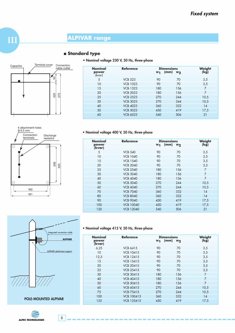
ALPIVAR range
Nominal Reference Dimensions Weightpower W1 (mm) W2 (kg)(kvar)
5 VCB 523 90 70 3,510 VCB 1023 90 70 3,515 VCB 1523 180 156 720 VCB 2023 180 156 725 VCB 2523 270 244 10,530 VCB 3023 270 244 10,540 VCB 4023 360 332 1450 VCB 5023 450 419 17,560 VCB 6023 540 506 21
Nominal Reference Dimensions Weight power W1 (mm) W2 (kg)(kvar)
5 VCB 540 90 70 3,510 VCB 1040 90 70 3,515 VCB 1540 90 70 3,520 VCB 2040 90 70 3,525 VCB 2540 180 156 730 VCB 3040 180 156 740 VCB 4040 180 156 750 VCB 5040 270 244 10,560 VCB 6040 270 244 10,570 VCB 7040 360 332 1480 VCB 8040 360 332 1490 VCB 9040 450 419 17,5100 VCB 10040 450 419 17,5120 VCB 12040 540 506 21
■ Standard type• Nominal voltage 230 V, 50 Hz, three-phase
• Nominal voltage 400 V, 50 Hz, three-phase
Nominal Reference Dimensions Weight power W1 (mm) W2 (kg)(kvar)6,25 VCB 6415 90 70 3,510 VCB 10415 90 70 3,5
12,5 VCB 12415 90 70 3,515 VCB 15415 90 70 3,520 VCB 20415 90 70 3,525 VCB 25415 90 70 3,530 VCB 30415 180 156 740 VCB 40415 180 156 750 VCB 50415 180 156 760 VCB 60415 270 244 10,575 VCB 75415 270 244 10,5100 VCB 100415 360 332 14125 VCB 125415 450 419 17,5
• Nominal voltage 415 V, 50 Hz, three-phase
Fixed system
ALPIVAR
Integrated connection cable
ALPIVAR attachment support
Terminal cover Connection cable outlet
Capacitor
220
55
275
Connection terminals
Dischargeresistors
4 attachment holesφ 6.5 mm
208
225
W2
W1
POLE-MOUNTED ALPIVAR
III

9
ALPIVAR range
Power Nominal Reference Dimensions Weightdelivered at 400 V power W1 (mm) W2 (kg)
(kvar) (kvar)5 6,25 VCB 644 90 70 3,510 12,5 VCB 1244 90 70 3,5
12,5 15 VCB 1544 90 70 3,516,5 20 VCB 2044 90 70 3,520 25 VCB 2544 90 70 3,525 30 VCB 3044 180 156 733 40 VCB 4044 180 156 740 50 VCB 5044 180 156 750 60 VCB 6044 270 244 10,560 75 VCB 7544 270 244 10,566 80 VCB 8044 360 332 1475 90 VCB 9044 360 332 1480 100 VCB10044 360 332 14100 125 VCB 12544 450 419 17,5
■ H type • Nominal voltage 440 V, 50 Hz, three-phase
Power Nominal Reference Dimensions Weightdelivered at 400 V power W X D X H (mm) (kg)
(kvar) (kvar)cubicle
25 30 VS 3044 600 x 500 x 1400 10050 60 VS 6044 600 x 500 x 1400 12075 90 VS 9044 600 x 500 x 1400 140100 120 VS 12044 600 x 500 x 1400 160125 150 VS 15044 800 x 500 x 2100 200160 200 VS 20044 800 x 500 x 2100 230200 250 VS 25044 800 x 500 x 2100 260240 300 VS 30044 800 x 500 x 2100 290280 350 VS 35044 800 x 500 x 2100 320
■ Anti-harmonic reactors or SAH type• Nominal voltage 440 V, 50 Hz, three-phase• Alpivar SAH type units consist of Alpivar capacitors combined with anti-harmonic
reactors, mounted and wired in IP 315 cubicles.
■ Harmonic filter or FH type : consult us
Fixed system
III

10
ALPIBLOCIVALPIBLOC units comprise ALPIVAR capacitor with built-in circuit breakers, mounted and wired inboxes or IP315 cubicles.
These ready-to-connect units are designed for fixed compensation of low and medium-poweredelectrical equipment.
For some applications (e.g. remote control) the circuit breaker may be replaced by a contactor andHRC fuses.
Nominal Reference Circuit breaker Dimensions Weightpower Icu W X D X H (mm) (kg)(kvar) (kA)
10 B 1040 10 190 x 230 x 380 515 B 1540 10 190 x 230 x 380 520 B 2040 10 190 x 230 x 380 525 B 2540 10 190 x 230 x 380 1030 B 3040 10 190 x 230 x 380 1040 B 4040 16 365 x 230 x 380 1250 B 5040 16 365 x 230 x 380 1560 B 6040 16 365 x 230 x 380 1570 B 7040 16 365 x 230 x 380 2080 B 8040 16 365 x 230 x 380 2090 B 9040 35 540 x 230 x 380 25100 B 10040 35 540 x 230 x 380 28120 B 12040 35 540 x 230 x 380 30
■ Standard type• Nominal voltage 400 V, 50 Hz, three-phase
Power Nominal Reference Circuit breaker Dimensions Weight delivered at 400 V power Icu W X D X H (mm) (kg)
(kvar) (kvar) (kA)
10 12,5 B 1244 10 190 x 230 x 380 512,5 15 B 1544 10 190 x 230 x 380 516,5 20 B 2044 10 190 x 230 x 380 520 25 B 2544 10 190 x 230 x 380 525 30 B 3044 10 190 x 230 x 380 1033 40 B 4044 16 365 x 230 x 380 1240 50 B 5044 16 365 x 230 x 380 1550 60 B 6044 16 365 x 230 x 380 1560 70 B 7044 16 365 x 230 x 380 2066 80 B 8044 16 365 x 230 x 380 2075 90 B 9044 35 540 x 230 x 380 2580 100 B 10044 35 540 x 230 x 380 28100 120 B 12044 35 540 x 230 x 380 30
■ H type• Nominal voltage 440 V, 50 Hz, three-phase
Fixed system
ALPIBLOC range

11
ALPIBLOC range
Power Nominal Reference Circuit breaker Dimensions Weight delivered at 400 V power Icu W X D X H (mm) (kg)
(kvar) (kvar) (kA)cubicle
25 30 BS 3044 10 600 x 500 x 1400 11050 60 BS 6044 16 600 x 500 x 1400 15075 90 BS 9044 35 600 x 500 x 1900 170100 120 BS 12044 35 600 x 500 x 1900 180125 150 BS 15044 35 800 x 500 x 2100 200160 200 BS 20044 35 800 x 500 x 2100 230200 250 BS 25044 35 800 x 500 x 2100 260240 300 BS 30044 35 800 x 500 x 2100 290280 350 BS 35044 50 800 x 500 x 2100 320
■ Anti-harmonic reactors or SAH type • Nominal voltage 440 V, 50 Hz, three-phase• ALPIBLOC SAH type units consist of Alpivar capacitors combined with anti-harmonic
reactors and a main circuit breaker, mounted and wired in IP 315 cubicles
■ Harmonic Filter or FH type : consult us
Fixed system
NOTE: the Icu rating of the circuit breakers may be modified on request.
IV
Rank 5 harmonic filter (250 Hz), 900 kvar – 500 V
Filtering capacity – Harmonic 5: 600 A

12
COMPENSATION KITSVCompensation kits comprise :
• ALPIVAR panels : standard type and H type• ALPIVAR racks : SAH type• accessories for panels and racks• power factor controllers
ALPIVAR panels and racks are factory wired units designed to be integrated in universal cubicles aspart of automatic compensation systems.
Automatic system
Alpivar panel range
Nominal Reference Weightpower (kg)(kvar)
10 P5.5 - 1040 510 + 10 P5.5 - 10 + 1040 1020 P5.5 - 2040 820 + 20 P5.5 - 20 + 2040 1620 + 40 P5.5 - 20 + 4040 1940 P5.5 - 4040 1440 + 40 P5.5 - 40 + 4040 2380 P5.5 - 8040 22
12,5 P5.5 - 1240 612,5 + 12,5 P5.5 - 12 + 1240 1125 P5.5 - 2540 925 + 25 P5.5 - 25 + 2540 1625 + 50 P5.5 - 25 + 5040 2250 P5.5 - 5040 1675 P5.5 - 7540 22
15 P5.5 - 1540 715 + 15 P5.5 - 15 + 1540 1330 P5.5 - 3040 1030 + 30 P5.5 - 30 + 3040 2060 P5.5 - 6040 19
■ Standard type• Nominal voltage 400 V, 50 Hz, three-phase
200
248
500
525
550
150
Attachment slots14 X 7 mm Attachment holes
ø 7 mm
Junction bars
160
400
240

13
■ Composition of Alpivar panels- 1 ALPIVAR capacitor
- 1 contactor suitable for handling capacitive currents
- 1 set of 3 HRC fuses
- 1 set of modular copper busbars with junction bars for connecting several panels in parallel
- 1 steel frame on which the components are assembled and wired.
Automatic system
Power Nominal Reference Weightdelivered at 400 V power (kg)
(kvar) (kvar)
10 12,5 P5.5 - 1244 610 + 10 12,5 + 12,5 P5.5 - 12 + 1244 1220 25 P5.5 - 2544 1020 + 20 25 + 25 P5.5 - 25 + 2544 2020 + 40 25 + 50 P5.5 - 25 + 5044 2340 50 P5.5 - 5044 1660 75 P5.5 - 7544 2280 100 P5.5 - 10044 24
12,5 15 P5.5 - 1544 712,5 + 12,5 15 + 15 P5.5 - 15 + 1544 1425 30 P5.5 - 3044 1025 + 50 30 +60 P5.5 - 30 + 6044 2350 60 P5.5 - 6044 1775 90 P5.5 - 9044 23
16,5 20 P5.5 - 2044 816,5 + 16,5 20 + 20 P5.5 - 20 + 2044 1616,5 + 33 20 + 40 P5.5 - 20 + 4044 1933 40 P5.5 - 4044 1433 + 33 40 + 40 P5.5 - 40 + 4044 2366 80 P5.5 - 8044 22
■ H type • Nominal voltage 440 V, 50 Hz, three-phase
200
248
500
525
550
150
Attachment slots14 X 7 mm Attachment holes
ø 7 mm
Junction bars
160
400
240
V

14
■ Composition of the rack- 1 Alpivar capacitor- 1 contactor suitable for handling capacitive currents- 1 anti harmonic reactor with thermal protection- 1 set of 3 HRC fuses- 1 set of modular copper busbars with junction bars
for connecting several panels in parallel- 1 steel frame on which the components are assembled and wired.
Alpivar rack range
Power Nominal Reference Weight delivered at 400 V power (kg)
(kvar) (kvar)
6,25 7,5 R4.6 - 744 206,25 + 6,25 7,5 + 7,5 R4.6 - 7 + 744 2512,5 15 R4.6 - 1544 3012,5 + 12,5 15 + 15 R4.6 - 15 + 1544 3525 30 R4.6 - 3044 4050 60 R4.6 - 6044 60
20 25 R7 - 2544 3540 50 R7 - 5044 5080 100 R7 - 10044 80
■ Anti-harmonic reactors or SAH type • Nominal voltage 440 V, 50 Hz, three-phase
Automatic system
Note: only racks of the same type (R4.6, R7) can be coupled together.
325
460
425
460
460
375
R 4.6
325
700
665
700
460
375 R 7
Attachment slots 24 X 8,2
Attachment holes ø : 8,2
Junction bars
Rack attachment
V
type type

I
15
DCRE Power factor controllers use a microprocessor to provide digital control of capacitor banks. Thistechnology enables the power factor (Cos ϕ) to be measured and read accurately and reliably even onnetworks with strong harmonic interference.
■ GENERAL CHARACTERISTICS
• flush mounting• protection index IP 41• operating temperature: -10 / +60°C• standards: IEC 60255-5 and 6
IEC 60068-2 and 6EN 50081-1 and 50082-2
• part numbers for different sizes of capacitor bank❋ DCRE 5 : 5 steps❋ DCRE 7 : 7 steps❋ DCRE 12 : 12 steps
• dimensions and weight❋ DCRE 5 : 96 x 96 x 62 (mm) - 0,36 kg❋ DCRE 7 : 144 x 144 x 62 (mm) - 0,67 kg❋ DCRE 12 : 144 x 144 x 62 (mm) - 0,67 kg
■ ELECTRICAL CHARACTERISTICS
• Current input by C.T❋ primary: rating depending on installation❋ secondary: 5 A (1 A on request)❋ power: 10 VA (recommended) – class 1
• Voltage input❋ direct as standard: 380 / 415 V❋ direct on request: 220 / 240 V❋ external transformer for other voltages
• Frequency 50 / 60 Hz■ SPECIFIC CHARACTERISTICS
• current transformer connection direction irrelevant• phase rotation direction irrelevant• connection:
❋ C.T on one phase: L1❋ voltage on the other two phases: L2 and L3
• dry contact alarm outputs■ SETTINGS AND PARAMETERS
• Cos ϕ: 0.85 ind. to 0.95 cap.• Staging: all possible combinations: 1.1.1 / 1.2.2.2 / 1.2.3.4 / etc.• Adjustable reconnection time for a given step • Adjustable trigger time for all steps
For more detailed information, consult our manual DCRE
for panel or rack sets- one set of three copper studs (30 x 10) with screws for customer connection : Part No. PRC 3010
for panels and racks- IP 2X protection against direct contact with parts under power (busbars, HRC fuses, etc.) : Part No. KIT 2X
Accessories for panels and racks
Power factor controllers
Automatic system
Note: consult us for power factor controller for standalone power generation units (micro power plant, wind turbine, etc.)
V

16
ALPIMATICVI
ALPIMATIC capacitor banks are automatic banks using electromechanical switching. They comprisepanels or racks:
• panels for M series (standard and H ranges)• racks for MS series (SAH range)
The units and their power factor controller are integrated in cubicles.
■ GENERAL CHARACTERISTICS
• IP 315 box or cubicle• protection of parts under power against direct contact: IP 2X• temperature class
❋ operation: -10 / +45°C (average over 24 hours: 40°C)❋ storage: -30 / +60°C
• ventilation: natural or forced depending on power rating• colour: grey cubicle (RAL 7032)
black base• standards: EN 60439-1,
IEC 60439-1 and 2
■ SPECIFIC CHARACTERISTICS
• fully modular design for easy extension and maintenance•power factor controller with simplified commissioning procedure• extendable cubicle:
❋ standard for main power ratings❋ optional for others
• cables enter at the bottom (at the top on request)
■ ELECTRICAL CHARACTERISTICS
• Insulation class: 0.66 kV (tested at 2.5 kV, 50 Hz for one minute)• built-in power supply for auxiliary circuits• built-in connection terminal block for brown-out contact (generator unit, etc.)• possible remote alarm output
■ OPTIONS
• protection circuit breaker• fixed step• adder-type current transformer
■ CONNECTIONS
Allow for: • power cables as per table on page 26• current transformer to be located on phase L1 of the facility, upline from all receivers
and the capacitor bank.❋ primary: rating depending on installation❋ secondary: 5 A (1 A on request)❋ power: 10 VA (recommended) – class 1
• note: this transformer can be supplied separately on request.
Automatic system
VI

ALPIMATIC range
■ Standard type• nominal voltage 400 V 50 Hz three-phase
17
Automatic system
Nominal Electrical Reference Dimensions Weight Possiblepower steps W X D X H (mm) (kg) extensions(kvar) (kvar) (kvar)
box12,5 5 x 2,5 M 1240 250 x 350 x 750 40 on request
15 3 x 5 M 1540 250 x 350 x 750 40 on request
20 4 x 5 M 2040 250 x 350 x 750 40 on request
25 5 x 5 M 2540 250 x 350 x 750 40 on request
30 6 x 5 M 3040 250 x 350 x 750 45 on request
35 7 x 5 M 3540 250 x 350 x 750 45 on request
40 4 x 10 M 4040 250 x 350 x 750 45 on request
45 3 x 15 M 4540 250 x 350 x 750 45 on request
50 5 x 10 M 5040 250 x 350 x 750 45 on request
cubicle
60 3 x 20 M 6040 350 x 500 x 1000 70 on request
70 7 x 10 M 7040 350 x 500 x 1000 75 on request
80 4 x 20 M 8040 350 x 500 x 1000 75 on request
90 6 x 15 M 9040 350 x 500 x 1000 80 on request
100 5 x 20 M 10040 350 x 500 x 1000 80 on request
120 6 x 20 M 12040 350 x 500 x 1000 90 on request
cubicle
140 7 x 20 M 14040 600 x 500 x 1400 110 160
160 4 x 40 M 16040 600 x 500 x 1400 125 160
180 9 x 20 M 18040 600 x 500 x 1400 140 80
200 5 x 40 M 20040 600 x 500 x 1400 150 80
220 11 x 20 M 22040 600 x 500 x 1400 160 80
240 6 x 40 M 24040 600 x 500 x 1400 170 80
260 13 x 20 M 26040 600 x 500 x 1400 180 on request
280 7 x 40 M 28040 600 x 500 x 1400 190 on request
300 15 x 20 M 30040 600 x 500 x 1400 200 on request
320 8 x 40 M 32040 600 x 500 x 1400 210 on request
cubicle
360 9 x 40 M 36040 600 x 500 x 1900 250 80
400 10 x 40 M 40040 600 x 500 x 1900 270 80
440 11 x 40 M 44040 600 x 500 x 1900 290 on request
480 12 x 40 M 48040 600 x 500 x 1900 310 on request
cubicle
520 13 x 40 M 52040 1200 x 500 x 1400 370 80
560 14 x 40 M 56040 1200 x 500 x 1400 400 80
600 15 x 40 M 60040 1200 x 500 x 1400 430 on request
640 16 x 40 M 64040 1200 x 500 x 1400 450 on request
cubicle
720 9 x 80 M 72040 1200 x 500 x 1900 500 240
800 10 x 80 M 80040 1200 x 500 x 1900 540 160
VI
Consult us for dimensions of cubicles with built-in circuit breakers

18
ALPIMATIC range
■ H type • nominal voltage 440 V 50 Hz three-phase
Automatic system
Power Nominal Electrical Reference Dimensions Weight Possibledelivered power steps W X D X H (mm) (kg) extensionsat 400 V (kvar) (kvar) (kvar)
(kvar)
box12,5 15 5 x 3 M 1544 250 x 350 x 750 40 on request
15 18 3 x 6,25 M 1844 250 x 350 x 750 40 on request
20 25 4 x 6,25 M 2544 250 x 350 x 750 40 on request
25 31,25 5 x 6,25 M 3144 250 x 350 x 750 40 on request
30 37,5 6 x 6,25 M 3744 250 x 350 x 750 45 on request
35 43,75 7 x 6,25 M 4344 250 x 350 x 750 45 on request
40 50 4 x 12,5 M 5044 250 x 350 x 750 45 on request
45 55 3 x 18 M 5544 250 x 350 x 750 45 on request
50 62,5 5 x 12,5 M 6244 250 x 350 x 750 45 on request
cubicle
60 75 3 x 25 M 7544 350 x 500 x 1000 75 on request
70 85 7 x 12,5 M 8544 350 x 500 x 1000 80 on request
80 100 4 x 25 M 10044 350 x 500 x 1000 80 on request
90 110 6 x 18 M 11044 350 x 500 x 1000 90 on request
100 125 5 x 25 M 12544 350 x 500 x 1000 110 on request
120 150 6 x 25 M 15044 350 x 500 x 1000 110 on request
cubicle
140 175 7 x 25 M 17544 600 x 500 x 1400 125 200
160 200 4 x 50 M 20044 600 x 500 x 1400 125 200
180 225 9 x 25 M 22544 600 x 500 x 1400 135 100
200 250 5 x 50 M 25044 600 x 500 x 1400 150 100
220 275 11 x 25 M 27544 600 x 500 x 1400 160 100
240 300 6 x 50 M 30044 600 x 500 x 1400 170 100
260 325 13 x 25 M 32544 600 x 500 x 1400 180 on request
280 350 7 x 50 M 35044 600 x 500 x 1400 190 on request
300 375 15 x 25 M 37544 600 x 500 x 1400 200 on request
320 400 8 x 50 M 40044 600 x 500 x 1400 210 on request
cubicle
360 450 9 x 50 M 45044 600 x 500 x 1900 250 100
400 500 10 x 50 M 50044 600 x 500 x 1900 270 100
440 550 11 x 50 M 55044 600 x 500 x 1900 290 on request
480 600 12 x 50 M 60044 600 x 500 x 1900 310 on request
cubicle
520 650 13 x 50 M 65044 1200 x 500 x 1400 370 100
560 700 14 x 50 M 70044 1200 x 500 x 1400 400 100
600 750 15 x 50 M 75044 1200 x 500 x 1400 430 on request
640 800 16 x 50 M 80044 1200 x 500 x 1400 450 on request
cubicle
720 900 9 x 100 M 90044 1200 x 500 x 1900 500 300
800 1000 10 x 100 M 100044 1200 x 500 x 1900 540 200
VI
Consult us for dimensions of cubicles with built-in circuit breakers

19
■ Anti-harmonic reactors or SAH type• nominal voltage 440 V 50 Hz three-phase
ALPIMATIC range
Automatic system
Power Nominal Electrical Reference Dimensions Weight Possibledelivered power steps W X D X H (mm) (kg) extensionsat 400 V (kvar) (kvar) (kvar)
(kvar)
cubicle25 30 4 x 7,5 MS 3044 600 x 500 x 1400 90 30
37,5 45 6 x 7,5 MS 4544 600 x 500 x 1400 110 30
50 60 4 x 15 MS 6044 600 x 500 x 1400 130 30
62,5 75 5 x 15 MS 7544 600 x 500 x 1400 150 on request
75 90 3 x 30 MS 9044 600 x 500 x 1400 170 60
100 120 4 x 30 MS 12044 600 x 500 x 1400 210 on request
125 150 5 x 30 MS 15044 600 x 500 x 1400 240 on request
160 200 4 x 50 MS 20044 800 x 500 x 2100 300 200
200 250 5 x 50 MS 25044 800 x 500 x 2100 340 200
240 300 6 x 50 MS 30044 800 x 500 x 2100 370 100
280 350 7 x 50 MS 35044 800 x 500 x 2100 400 100
320 400 8 x 50 MS 40044 800 x 500 x 2100 430 on request
360 450 9 x 50 MS 45044 800 x 500 x 2100 470 on request
400 500 5 x 100 MS 50044 800 x 500 x 2100 520 on request
440 550 11 x 50 MS 55044 1600 x 500 x 2100 600 400
480 600 6 x 100 MS 60044 1600 x 500 x 2100 630 400
520 650 13 x 50 MS 65044 1600 x 500 x 2100 670 300
560 700 7 x 100 MS 70044 1600 x 500 x 2100 700 300
600 750 15 x 50 MS 75044 1600 x 500 x 2100 730 200
640 800 8 x 100 MS 80044 1600 x 500 x 2100 800 200
720 900 9 x 100 MS 90044 1600 x 500 x 2100 860 100
800 1000 10 x 100 MS 100044 1600 x 500 x 2100 1000 on request
■ Harmonic filter or FH type : consult us
VI
Rank 5 (250 Hz) and 7 (350 Hz) harmonic filter, 500 kvar – 400 V
Filtering capacity – Harmonic 5 : 350 A – Harmonic 7 : 250 A
Consult us for dimensions of cubicles with built-in circuit breakers

20
ALPES TECHNOLOGIES, one of the leaders in reactive energy compensation and harmonic filtering,offers a new automatic capacitor bank concept : ALPISTATIC
ALPISTATIC is a low voltage real-time reactive power compensation unit using solid state switches.
To face increasingly sophisticated industrial processes including large numbers of devices sensitive tovoltage variations (PLCs, industrial computers, etc.) or having ultra-fast cycles (robots, weldingmachines, variable speed drives, etc.), ALPES TECHNOLOGIES developed ALPISTATIC.
ALPISTATIC is a “soft, fast” reactive energy compensation system suitable for this new generation ofreceiving devices.
ALPISTATIC has three main advantages compared with conventional systems using electromechanicalswitching :
• no transient currents when capacitors are triggered which might cause voltagetroughs.
• no transient excess voltages or triggering of capacitors due to difficulties in cuttingoff the electrical arc.
• very short response time: 40 milliseconds.
ALPISTATIC is primarily designed for :
• compensation for the power factor (cos ϕ) of main low voltage switchboards
• consumers wishing to reduce their total electricity consumption
• independent energy generators to optimise units (generator units, etc.).
ALPISTATIC is particularly suitable for providing compensation for receivers :
• which do not accept transient currents or voltage (PLCs, computer equipment, ...)
• with ultra-fast cycles (welding machines, lifts, robots, variable speed drives, ...)
• with pulsating torques (roll mills, compressors, reciprocating saws, ...)
• which generate flicker (devices with extremely inductive loads, arc furnaces,welding machines, ...)
ALPISTATICVII
Automatic system

21
Automatic system
main characteristics compared
SENSITIVE DATA ALPISTATIC CONVENTIONAL
Presence of electromechanical contactors No Yes
Wear of moving parts No Yes
Contact bounce phenomenon No Possible
Contact fatigue None High
Transient excess currents No Yes (may exceed 200 In)when stages are triggered or released
Transient under-voltages None Yes (up to 100%)
Compatibility Excellent Average(PLCs, computer equipment, etc.)
Compatibility Excellent Poor(welding machines, generators, etc.)
Trigger and release response time 40 milliseconds approx. 30 seconds
Number of operations Unlimited Limited (electromechanical contactor)
Sound level during operation None Low (electromechanical contactor)
Reduced flicker Yes (for highly inductive loads) No
Creation of harmonics No No
VII

22
■ Conventional switching using electromechanical contactors
■ Soft switching using ALPISTATIC solid state contactors
• during switching, the following may occur :
❋ transient overcurrents exceeding 200 In
❋ significant transient over and under-voltages
These disturbances may lead to malfunctions on control equipment (PLCs, industrial computers, ...).
Coupling a stage Uncoupling a stage
Coupling a stage Uncoupling a stage
• soft switching using Alpistatic solid state contactors prevents network disturbance• the reaction speed (40 milliseconds) ensures that power is controlled immediately
Network voltage and current when coupling and uncoupling a capacitor stageVII
Automatic system

23
ALPISTATIC COMPOSITION AND CHARACTERISTICS
ALPISTATIC includes:
• a capacitor bank split into several steps depending on the compensator power rating
• one three-pole solid state contactor per step (cutting all three phases)
• fan-cooled heat sink on each solid state contactor
• one anti-harmonic reactor per step, protecting the solid state contactor andpreventing harmonics
• one set of three HRC fuses per stage
• a control system for the solid state contactors, including :
❋ a reactive energy controller for automatic control
- with automatic / manual operation
- front panel display showing the number of stages operating
- front panel display of cos ϕ.
- front panel display of many other electrical parameters(harmonics, ...)
❋ microprocessor instrumentation and control board using solid statecontactors :
- triggers and releases contactors within 40 milliseconds
- avoids any transient voltages and currents when steps aretriggered or released.
■ GENERAL CHARACTERISTICS
• IP 315 cubicle• protection of parts under power against direct contact : IP 2X• temperature class
❋ operation : -10 / +45°C (average over 24 hours: 40°C)❋ storage : -30 / +60°C
• ventilation : forced • colour : ❋ grey cubicle (RAL 7032),
❋ black base• cables enter at the bottom (at the top on request)• standards : EN 60439-1,
IEC 60439-1 and 2
■ ELECTRICAL CHARACTERISTICS
• Insulation class : 0.66 kV (tested at 2.5 kV, 50 Hz for one minute)• built-in power supply for auxiliary circuits• built-in connection terminal block for brown-out contact
■ OPTIONS• protection circuit breaker• fixed step• adder-type current transformer
■ CONNECTIONSAllow for: • power cables as per table on page 26
• current transformer to be located on phase L1 of the facility, upline from all receiversand the capacitor bank.
❋ primary : rating depending on installation❋ secondary : 5 A (1 A on request)❋ power : 10 VA (recommended) – class 1
• note: this transformer can be supplied separately on request.
Automatic system
VII

24
Automatic system
■ Anti-harmonic reactors or SAH type • nominal voltage 440 V 50 Hz three-phase
ALPISTATIC range
Power Nominal Electrical Reference Dimensions Weight Possibledelivered power steps W X D X H (mm) (kg) extensionsat 400 V (kvar) (kvar) (kvar)
(kvar)
cubicle
100 120 4 x 30 STS 12044 1000 x 600 x 2100 210 100
125 150 5 x 30 STS 15044 1000 x 600 x 2100 240 100
160 200 4 x 50 STS 20044 1000 x 600 x 2100 280 100
200 250 5 x 50 STS 25044 1000 x 600 x 2100 320 100
240 300 6 x 50 STS 30044 1000 x 600 x 2100 360 on request
280 350 7 x 50 STS 35044 1000 x 600 x 2100 400 on request
320 400 8 x 50 STS 40044 1000 x 600 x 2100 430 on request
360 450 9 x 50 STS 45044 1000 x 600 x 2100 460 on request
400 500 5 x 100 STS 50044 1000 x 600 x 2100 500 on request
440 550 11 x 50 STS 55044 1000 x 600 x 2100 530 on request
480 600 6 x 100 STS 60044 2000 x 600 x 2100 630 200
520 650 13 x 50 STS 65044 2000 x 600 x 2100 660 100
560 700 7 x 100 STS 70044 2000 x 600 x 2100 690 100
600 750 15 x 50 STS 75044 2000 x 600 x 2100 720 on request
640 800 8x 100 STS 80044 2000 x 600 x 2100 750 on request
720 900 6 x 150 STS 90044 2000 x 600 x 2100 810 300
840 1050 7 x 150 STS 105044 2000 x 600 x 2100 870 150
960 1200 8 x 150 STS 120044 2000 x 600 x 2100 930 on request
VII
Consult us for dimensions of cubicles with built-in circuit breakers

Specific ranges VIII
25
The ALPIVAR - ALPIBLOC - PANEL - RACK - ALPIMATIC andALPISTATIC product ranges described in this catalogue correspond tothe most common standard units. All of these products can bemanufactured for other electrical characteristics (frequency, voltage,power, coupling, etc.) and in particular:
• frequency 60 Hz and other frequencies for special applications
• single-phase voltages
• dual voltage with retained power
• other standard voltages: 240 - 415 - 480 - 500 - 530 - 550 -600 - 690 - 800 V ...
• other power ratings on request.
Please contact our technical sales department with your specialrequests.

26
IX
Note:The cable cross-section indicated in this table is the minimum recommended section. It does not take into accountadditional correcting factors (fitting method, temperature, long distances, etc.). The calculations are for unipolarcables mounted in ambient air at 30°C.
Three-phase 400 V and 440 V Three-phase circuit breaker Cablescapacitor Rating / thermal setting minimum cross-section per phase
Nominal power (A) Cu (mm2) Al (mm2)(kvar)
10 20/20 6 1020 40/40 10 1630 63/60 16 2540 80/80 25 3550 100/100 35 5060 125/125 35 5070 160/140 35 5080 160/160 50 7090 200/180 50 70100 200/200 70 95125 250/250 70 95150 400/300 95 120175 400/350 120 185200 400/400 150 240225 630/450 150 240250 630/500 185 2 x 120275 630/550 185 2 x 120300 630/600 2 x 95 2 x150325 630/630 2 x 95 2 x 150350 800/700 2 x 120 2 x 185375 800/750 2 x 120 2 x 185400 800/800 2 x 150 2 x 240450 1000/900 2 x 150 2 x 240500 1000/1000 2 x 185 4 x 150550 1250/1100 2 x 185 4 x 150600 1250/1200 4 x 120 4 x 185650 1250/1250 4 x 120 4 x 185700 1600/1400 4 x 150 4 x 240750 1600/1500 4 x 150 4 x 240800 1600/1600 4 x 150 4 x 240850 2000/1700 4 x 150 4 x 240900 2000/1800 4 x 150 4 x 240950 2000/1900 4 x 185 4 x 3001000 2000/2000 4 x 185 4 x 300
Circuit breakers and cables
Protective circuit breaker and connection cableselection table for capacitors

P.A.E. Les Glaisins - 7, rue des Bouvières - B.P. 33274943 ANNECY-LE-VIEUX CEDEX FRANCETél. : 33 (0)4 50 64 05 13 - Fax : 33 (0)4 50 64 04 37www.alptech.fr - Email : [email protected]
AN
NEC
Y IM
PRES
SIO
N -
SEYN
OD
- Té
l. 04
50
69 1
2 39
© Copyright Alpes Technologies 2000
■ The characteristics of our units are given for information only, and are onlybinding after confirmation by our services.
2002
-B.T.
01 -
ANG