low velocity impact analysis of laminated frp composites · low velocity impact analysis of...
TRANSCRIPT

IJAMR: Vol. 4, No. 1, January-June 2012; pp. 37-52© International Science Press, ISSN: 0975-6108
Low Velocity Impact Analysis of Laminated FRP Composites
B. Kranthi Kumar1 and Lakshmana Kishore T.2
1Department of Mechanical Engineering, Godavari Institute of Engineering and Technology, Rajahmundry,Andhrapradesh, India, (E-mail: [email protected])
2Department of Mechanical Engineering, Godavari Institute of Engineering and Technology, Rajahmundry,Andhrapradesh, India, (E-mail:[email protected])
ABSTRACT
Fiber reinforced composites have become increasingly important over the past few years and arenow the first choice for fabricating structures where low weight in combination with high strengthand stiffness are required. Fiber Reinforced Plastics (FRP) composites are in greatest commercialuse. They have been extensively used in aerospace, automotive, marine and construction industriesdue to their inherent advantages over conventional metals. Failure modes of such laminated structuresare also different than those of conventional metallic materials. Impact is one such great designlimitation criteria involved in designing new composite products.
The present work is aimed at gaining an initial understanding of the impact behavior of fiberglassreinforced laminates with vinylester and is polyester resins. The purpose of this research is tocharacterize the damage done to fiberglass laminates subjected to low velocity, high mass impact.The effect of adding a protective layer of rubber to the laminates is also investigated.
Finite element models are created with ANSYS/LS-DYNA onlinear finite element software. Thesemodels are used to simulate the drop tower tests and extended to thicker laminates as well as differentimpact speeds and impactor mass.
These models are able to predict approximate stresses and strains induced in the laminates duringthe impact which are compared to the damage from the drop tower tests.
Keywords: FRP, composites, vinylester, polyester resins, stress and strain.
1. INTRODUCTION
A Composite material is a material brought about by combining materials differing incomposition or form on a macro scale for the purpose of obtaining specific characteristicsand properties. The constituents retain their identity such that they can be physically identifiedand they exhibit an interface between one another. In addition, three other criteria arenormally satisfied before we call a material as composite. Firstly, both the constituentshave to be present in reasonable proportions. Secondly, the constituent phases should havedifferent properties, such that the composite properties are noticeably different from theproperties of the constituents. Lastly, a synthetic composite is usually produced bydeliberately mixing and combining the constituents by various means. The constituent thatis continuous and is often, but not always, present in the greater quantity in the composite

38 B. Kranthi Kumar and Lakshmana Kishore T.
is termed as the Matrix. The aim is to improve the properties of the matrix by incorporatinganother constituent. Generally used Matrix materials in composites are Polymers, Ceramicsand Metallic Matrix. Polymers have low strength and Young’s moduli, ceramics are strong,stiff and brittle, and metals have intermediate strength and Young’s moduli, together withgood ductility. The second constituent is known as the reinforcement, as it enhances themechanical properties of the matrix. The diameter of the fibers varies from 0.1- 100 µm.Strength and stiffness properties of reinforced elements are generally 10- 1000 times higherthan those of the matrix. At least one of the reinforcement is small, say <500µm andmechanical properties of composites are function of the shape, dimensions, orientation andquantity of the reinforcement.
2. FINITE ELEMENT ANALYSIS
Some of the first research on the modeling of impact damage resistance in Compositematerials was on the subject of bird strikes. In 1981, R.E McCarty [1] used the nonlinearfinite element software MAGNA to model birds striking the canopy of the F-16A and in1982; M.S. Hirschbein [2] used NASTRAN to model the effects of bird strikes on turbineblades. Both of these authors claimed reasonable results.
There have been many damage criterions created for composite damage analysis inLivermore's LS-DYNA transient non-linear FEA software [3]. One of the earliest wasestablished by Chang and Chang [4] in 1985. They created a damage model to predictdamage in notched laminate composites under tensile loading. The model could be used toassess the type and the extent of the damage, evaluate residual strengths, and predict ultimatestrengths. The damage was assessed with a proposed failure criteria and proposed propertydegradation model. They found excellent agreement between their predicted results andexperimental data. The current composite damage model that is used by LS-DYNA is basedon this model.
They identified the three main in plane failure modes as matrix cracking, fiber matrixshearing, and fiber breakage. The following failure criterion (equation 1) was used to predictmatrix cracking:
2
20
0
XY
XY
XY XY
Ym
t
XY XY
d
eY
d(1)
Where y is the transverse tensile stress
xy is the shear stress in each layer.
Yt is the transverse tensile strength,

Low Velocity Impact Analysis of Laminated FRP Composites 39
uxy is the ultimate shear strain and
em is the failure strain of the matrix material.
By adding the shear stress-shear strain relationship:
XY=
31XY XY
XYG (2)
where Sc is the ply shear strength.
For laminates with linear elastic behavior (a = 0),
As before, for linear elastic materials the equation can be reduced to:
2 2
2xyxf
t c
eX S
(3)
This failure criterion states that when the stresses x and
xy, in any one of the plies,
satisfy one of the previous equations (ef = 1), either fiber breakage or fiber-matrix shearing
occurs in that layer.
Once damage has occurred the material looses strength in that area and the reduction isdependent on the mode of failure. For matrix cracking in a layer, the transverse modulus Eyand Poisson’s ratio
y are reduced to zero. The longitudinal modulus Ex and the shear-stress
strain relation of that layer are unchanged
When fiber breakage and/or fiber-matrix shearing are predicted, the extent of the propertydegradation depends on the size of the damage. For fiber failure, both Ey and Ex are reducedto zero. The longitudinal modulus Ex and the shear modulus Gxy degenerate according tothe Weibull distribution:
0
exp 1dx
x
E A
E A (4)
2.1 Elements Used
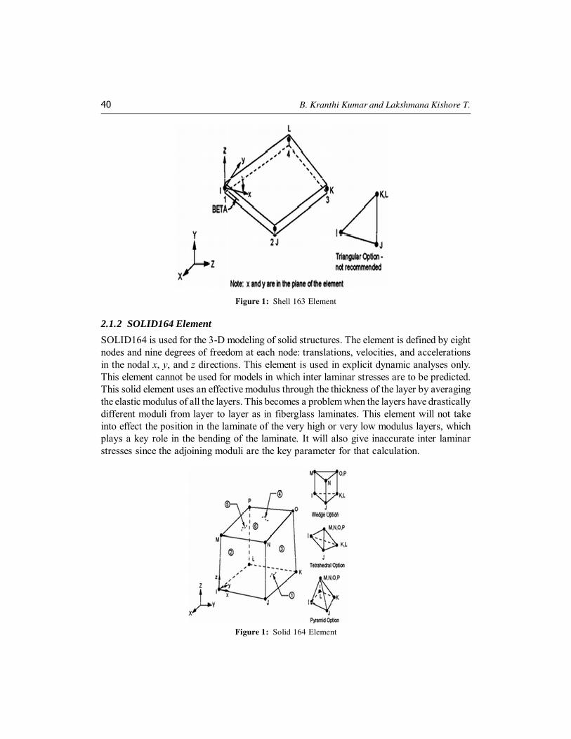
Due to advantages and disadvantages of one element over the other, as well as the parametersto be determined in view, two elements are used in the total analysis. They are Shell 163element and Solid 164 element.
2.1.1 SHELL163 Element
SHELL163 is a 4-node element with both bending and membrane capabilities [5]. Both in-plane and normal loads are permitted. The element has 12 degrees of freedom at each node:translations, accelerations, and velocities in the nodal x, y, and z directions and rotationsabout the nodal x, y, and z-axes. This element is used in explicit dynamic analyses only.
40 B. Kranthi Kumar and Lakshmana Kishore T.
2.1.2 SOLID164 Element
SOLID164 is used for the 3-D modeling of solid structures. The element is defined by eightnodes and nine degrees of freedom at each node: translations, velocities, and accelerationsin the nodal x, y, and z directions. This element is used in explicit dynamic analyses only.This element cannot be used for models in which inter laminar stresses are to be predicted.This solid element uses an effective modulus through the thickness of the layer by averagingthe elastic modulus of all the layers. This becomes a problem when the layers have drasticallydifferent moduli from layer to layer as in fiberglass laminates. This element will not takeinto effect the position in the laminate of the very high or very low modulus layers, whichplays a key role in the bending of the laminate. It will also give inaccurate inter laminarstresses since the adjoining moduli are the key parameter for that calculation.
Figure 1: Shell 163 Element
Figure 1: Solid 164 Element

Low Velocity Impact Analysis of Laminated FRP Composites 41
3. METHODOLOGY : STATEMENT OF PROBLEM
The problem is to characterize the damage occurred to fiberglass laminates subjected tolow velocity, high mass impact. This subject is a crucial design question that appearsfrequently in the design of new composite products. Impact loads affect almost allcommercial composite products whether by design or by accident. This investigationattempted to provide initial insight into impact damage done to the fiberglass laminates byperforming several drop weight impact analyses with finite element models and predictedthe behavior of the laminates under different impact situations. Further research is neededto evaluate the effects of impact damage on specific applications.
3.1 Non-Linear Analysis
The non- linearity arising from the nature of material is called 'Material Non- linearity'. Allnon- linearities are solved by applying the loads slowly (dividing it into a number of smallload increments). The model is assumed to behave linearly for each load increment, and thechange in model shape is calculated at each increment. Stresses are updated from incrementto increment, until the full applied load is reached.
4. FINITE ELEMENT ANALYSIS
Finite element analysis is used to gain information about the behavior of the compositelaminates subjected to impact loading. Simple models are analyzed and more complexmodels are used to simulate additional parameters such as thick laminates and rubberprotecting the composite. FEA is used to predict the stresses and strains induced in thelaminate by a low velocity projectile. These stresses and strains can later be used to predictthe life span of the composite under various loading conditions. ANSYS and ANSYS/LS-DYNA finite element codes are used for the simulations.
4.1 STATIC MODEL
Initially a static model is created to get an idea of the loads caused by a 1.25 m. diametergranite rock. Several simple shell models are made with pressures in various locations. Theresulting stresses and strains are very low and well within the capability of the compositeeven without a rubber liner. From this it is decided that the impact is going to be the limitingfactor in the design.
4.2 Results and Discussions
The block is placed at several distances from the shell and dropped onto it. The maximumdeflection in the center of the shell converged to –0.3048 m as the initial distance isdecreased, table This final deflection compared to the static deflection represents an impactfactor of 2.2, which is close to the 2.0 predicted by mechanics of materials.

42 B. Kranthi Kumar and Lakshmana Kishore T.
4.3 Drop Tower Model
The next step is to model the drop tower test in order to predict stress and strain information.Two separate ANSYS/ LS-DYNA models are created in order to compare the results of thetwo and pick one to use to model the tests. One target is created with shell 163 elements andone with solid 164 elements. The shell element has the advantage of fewer elements anddegrees of freedom, which lowers the required computer time. The solid elements areadvantageous due to their capability to capture the through thickness effects of the deflectionand stress since more than one element is placed in the thickness direction.
4.3.1 Shell 163 Model
4.3.1.1 Problem Description
A 12.5 cm × 12.5 cm shell target whose thickness is 0.6 cm and with the laminate propertiesis used for the target and a sphere with 1.8 cm diameter is used to represent the round endof the impactor tup, figure 3. The shell is constrained in the Z direction around the edges tosimulate the clamp device and also constrained in all directions along two sides to preventrigid body motion.
Table 4.1Convergence of Deflection and Stress
Distance from target (mm) Deflection (µm) Stress Intensity (N/m2)
0.254 –0.11684 21.7
0.0254 –0.4826 9.1
0.00254 –0.4826 5.95
0.000254 –0.03048 5.775
0.0000254 –0.03048 5.705
Figure 3: Meshed Model of Square Shell Target

Low Velocity Impact Analysis of Laminated FRP Composites 43
4.3.1.2 Problems with Target Plate Shape
The above model used very similar boundary conditions as the test jig in the drop weighttower. However, these boundary conditions gave some strange results in the clamped regiondue to the bending and membrane actions of the shells. In order to remove the possibility ofthese effects and also to lower the number of degrees of freedom, a new model is created.This model consisted of a 7.5 cm diameter flat cylindrical shell with the z displacementsand out-of-plane rotations fixed around the outer edge.
4.3.1.3 Problems with Target Plate Mesh
A uniform mesh is often difficult with a cylindrical plate. If a triangular mesh is used,singularities are created at the center of the circle where the elements internal angles arevery small. ANSYS also does not recommend the triangular mesh option with shell 163elements therefore the quadrilateral mesh is used for all models. With the quadrilateralmesh the center elements have a slightly different shape than the elements on the outerrings of the circle; however, no irregularities are noticed with this mesh, figure 4shown above.
4.3.1.4 Results and Discussions
In order to verify the accuracy of the model, the impact force and the total energy wascompared with the experimental results. Both were within 15% of the experimental results.Figure 5 shows the impact force predicted along with the force history from the experimentalresults with an impact velocity of 2 m/s.
Figure 4: Cylindrical Target with Quadrilateral Mesh with Boundary Conditions Specified

44 B. Kranthi Kumar and Lakshmana Kishore T.
Figure 5: Force History and Predicted FEA
Figure 6: Energy-History Graph for Impactor Velocity of 2 m/s Shell 163 Element

Low Velocity Impact Analysis of Laminated FRP Composites 45
In dynamic finite element analysis, the hourglass energy is a large concern. Arepresentative energy plot from ANSYS/ LS-DYNA is shown in figure 6.
4.3.2 Solid 164 Model
4.3.2.1 Problem Description
A 7.5 cm diameter solid cylinder is used for the composite target and a 1.75 cm diametersphere is used for the steel impactor, figure 7. The solid elements are constrained with alltranslations fixed around the edges to simulate the clamped boundary conditions in thedrop tower tests. The spherical solid is given an initial velocity (2 m/sec) in the direction ofthe target as in the other models. The material properties used for this model are shown inthe tables listed below, table 4.2.
Table 4.2Material Properties Used for Composite Laminates
Apparent Laminate Properties Values
Ex N/m2 25.33 × 10⁹
Ey N/m2 6.58 × 10⁹
Ez N/m2 7.79 × 10⁹
Gxy
= Gyz
N/m2 6.20 × 10⁸
Gxz
N/m2 14.33 × 10⁸
xy =
xy0.22
xz0.239
Kg/m3 1.924 × 10³
Figure 7: Finite Element Model of the Impactor

46 B. Kranthi Kumar and Lakshmana Kishore T.
Drop Tower Tests Simulations
4.4.1 Test 1 - Vinylester Resin
4.4.1.1 Description
For this drop tower test, the impact mass is 5.5 kg and the impactor velocity just beforeimpact is 3.81 m/s. In the FEA model, the density of the sphere is adjusted to achieve thesame mass as the impactor. The target is modeled with solid 164 elements with a thicknessof 6 mm. A linear orthotropic material model is used for the composite laminate and linearisotropic properties for the steel impactor. These properties are listed in table 4.3
Figure 8: Energy - History Graphs for Impactor Velocity of 2 m/s Using Solid 164 Element
Table 4.3Material Properties Used for Composite Laminate
Apparent Laminate Properties values
Ex N/m2 27.14 ×10⁹
Ey N/m2 14.88 × 10⁹
Ez N/m2 7.79 × 10⁹
Gxz
= Gyz
N/m2 6.20 × 10⁸
Gxy
N/m2 10.33 × 10⁸
xy =
xy0.22
xz0.239
Kg/m3 1.924 × 10³

Low Velocity Impact Analysis of Laminated FRP Composites 47
These material properties are determined with the aid of the shareware program TheLaminator [6]. The individual material properties for each layer are given in Table 4.4, 4.5,4.6. These layer properties are inputted into the program along with the layer thickness andstacking sequence to determine the apparent material properties.
Table 4.4Material Properties for Each Layer
E1
E2
G12
V12
Roving (E-glass) 1.00 × 10⁷ 2.00 × 10⁶ 2.00 × 10⁶ 0.2
Mat material (isotropic) 1.00 ×10⁶ 1.00 × 10⁶ 4.00 × 10⁵ 0.28
Matrix (vinylester) 5.00 ×10⁵ 5.00 × 10⁵ 1.00 × 10⁵ 0.3
Table 4.5Lay-up of Isopolyester Laminate
Layer Thickness (mm)
317.5 mm Nexus 0
311.15 mm - 2 oz. OC 0.419
Resin 0.482
90 - 113 yield roving 0.787
Resin 0.482
311.15 mm - 2 oz. OC 0.419
Resin 0.482
90 - 113 yield roving 0.406
Resin 0.482
311.15 mm - 2 oz. OC 0.419
342.9 mm Nexus 0
Total 4.378
Table 4.6Lay-up of Vinylester Laminate
Layer Thickness(mm)
342.9 mm Nexus 0
311.15 mm - 2 oz. OC 0.381
Resin 0.482
84 - 113 yield roving 0.787
Resin 0.482
311.15 mm - 2 oz. OC 0.381
Resin 0.482Table Cont’d

48 B. Kranthi Kumar and Lakshmana Kishore T.
4.4.1.2 Results and Discussions
The impact force is first compared to the experimental data. From a curve fit of theexperimental acceleration data, the maximum impact force is found to be approximately7116.8 N. Five samples are tested with the same impact velocity and the maximum impactforce is almost identical in all samples. Figure 9 shows a comparison between theexperimental data and the predicted impact force verses time. The higher predicted impactforce can be attributed to the model not including the energy release due to the damage(delamination and matrix cracking).
Table 4.6 Cont’d
42 - 113 yield roving 0.406
Resin 0.482
311.15 mm - 2 oz. OC 0.381
Resin 0.482
84 - 113 yield roving 0.787
Resin 0.482
311.15 mm - 2 oz. OC 0.381
342.9 mm Nexus 0
Total 6.396
Figure 9: Force History and FEA Force for an Impactor Velocity of 3.81 m/s
Low Velocity Impact Analysis of Laminated FRP Composites 49
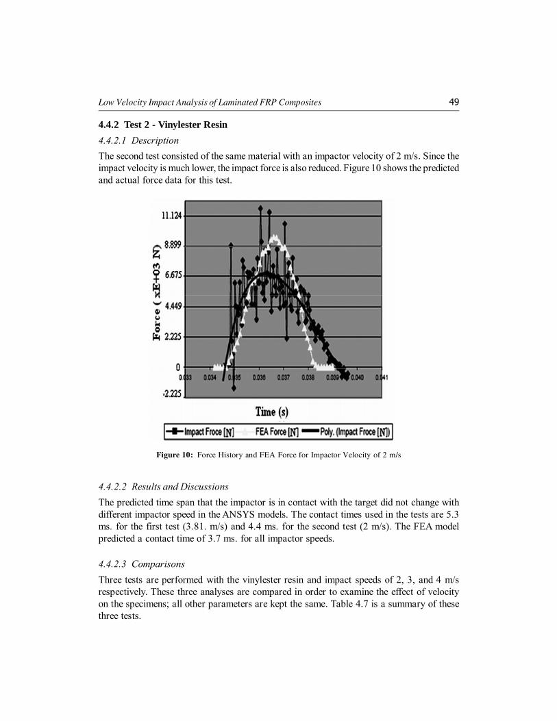
4.4.2 Test 2 - Vinylester Resin
4.4.2.1 Description
The second test consisted of the same material with an impactor velocity of 2 m/s. Since theimpact velocity is much lower, the impact force is also reduced. Figure 10 shows the predictedand actual force data for this test.
Figure 10: Force History and FEA Force for Impactor Velocity of 2 m/s
4.4.2.2 Results and Discussions
The predicted time span that the impactor is in contact with the target did not change withdifferent impactor speed in the ANSYS models. The contact times used in the tests are 5.3ms. for the first test (3.81. m/s) and 4.4 ms. for the second test (2 m/s). The FEA modelpredicted a contact time of 3.7 ms. for all impactor speeds.
4.4.2.3 Comparisons
Three tests are performed with the vinylester resin and impact speeds of 2, 3, and 4 m/srespectively. These three analyses are compared in order to examine the effect of velocityon the specimens; all other parameters are kept the same. Table 4.7 is a summary of thesethree tests.

50 B. Kranthi Kumar and Lakshmana Kishore T.
Based on comparisons of the predicted stress patterns on the bottom of the FEA modelsand the crack length, the cracks extend to the (175 – 245) × 106 N/m2 range on all three ofthese models. Further work could determine a stress range that initiates and continue matrixcracking and de-bonding.
4.4.2.4 Stress and Strain
The maximum predicted stress in the z direction for these three impactor speeds is shownin figure 11.
Table 4.7Comparison Between Test with Impact Speeds of 2, 3, and 4 m/
Impact Velocity (m/s) 2 3 4
Predicted maximum in-plane stress on top (N/m2) 300.3 × 10⁶ 477.4 × 10⁶ 651.7 × 10⁶
Predicted maximum in-plane stress on bottom (N/m2) 228.1 × 10⁶ 292.6 × 10⁶ 312.8 × 10⁶
Backside crack length (m) 0.0152 0.0533 0.0610
Figure 11: Maximum in-plane Stress for three Different Impactor Speeds (viz, 2, 3, and 4 m/s)

Low Velocity Impact Analysis of Laminated FRP Composites 51
As before, the predicted stress jumped quickly from the 2 to the 3 m/s case then leveledoff as the speed went to 4 m/s. The stress contour patterns were almost identical in eachcase with only the values of the stress regions changing. The strain in the X direction(maximum in-plane) also showed nearly identical contour patterns for all three cases. Thesestrains are shown in figure 12.
Figure 12: Maximum in-plane Stress for three Different Impactor Speeds (viz, 2, 3, and 4 m/s)
The “wavy” pattern in the high strain area is very interesting. This pattern is also seenin the external backside crack on some of the test samples. This is most likely due to theanisotropic nature of the laminate.
5. CONCLUSION
The purpose of this research is to examine the impact response of fiberglass reinforcedlaminates. Several drop weight tower impact analyses are performed on 12.5cm × 12.5 cmFRP plates with resins including vinylester and iso polyester. These test simulated highmass (5.5 kg) and low velocity (2-4 m/s) impact.
ANSYS/ LS-DYNA non-linear finite element analysis program is used to predict thestresses in the laminates during the impact. These stresses are then compared to the damage

52 B. Kranthi Kumar and Lakshmana Kishore T.
from the drop tests. The critical stress range for impact damage is in the range of (175-245)× 106 N/m2, which is very close to the static ultimate strength of the Duraspan laminates.
REFERENCES[1] R.E. McCarthy, “Finite Element Analysis of a bird-Resistant Monolithic Stretched Acrylic Canopy Design
for the F-16A Aircraft”. AIAA Aircraft Systems and Technology Mtg. Dayton, Ohio, Aug. 11-13 1981.
[2] Hirschbein, M.S., “Bird Impact Analysis Package for Turbine Fan Blades”. 23rd Structures, StructuralDynamics, and Materials Conference, New Orleans, LA, May 10-12 1992.
[3] LS-DYNA, “Livermore Software Technology Corporation”, 7374 Las Positas Rd., Livermore, CA 94550.
[4] Chang, F.K., and K.Y. Chang, “A Progressive Damage Model for Laminated Composites ContainingStress Concentrations”. J. Composite Mater. 21, (1997): pp. 834-855.
[5] Ansys Theory Manual, “Elements Reference”.
[6] The Laminator - Classical Analysis of Composite Laminates, http://www.thelaminator.net
[7] Ansys Theory Manual, “Elements Reference”.
[8] Cantwell, W.J., P. T. Curtis, and J. Morton, “Low Velocity Impact Damage Tolerance in CFRP LaminatesContaining Woven and Non-Woven Layer”. Composites. 14, (1983): pp. 301-305.
[9] Lui, D. “Impact Induced Delamination - A View of Bending Stiffness Mismatching”. Journal of CompositeMaterials. 22.
[10] Hou, J.P., N. Petrinic, and C. Ruiz, “A Delamination Criterion for Laminated Composites Under Low-Velocity Impact”. Composite Science and Technology. 61, (2001): pp. 2069-2074.
[11] Cantwell, W.J., and J. Morton, “The Impact Resistance of Composite Materials - a Review”, Composites.22, (1991): pp. 347-362.