permanent indentation characterization for low-velocity
TRANSCRIPT

HAL Id: hal-01851599https://hal.archives-ouvertes.fr/hal-01851599
Submitted on 30 Jul 2018
HAL is a multi-disciplinary open accessarchive for the deposit and dissemination of sci-entific research documents, whether they are pub-lished or not. The documents may come fromteaching and research institutions in France orabroad, or from public or private research centers.
L’archive ouverte pluridisciplinaire HAL, estdestinée au dépôt et à la diffusion de documentsscientifiques de niveau recherche, publiés ou non,émanant des établissements d’enseignement et derecherche français ou étrangers, des laboratoirespublics ou privés.
Permanent indentation characterization for low-velocityimpact modelling using three-point bending test
Natthawat Hongkarnjanakul, Samuel Rivallant, Christophe Bouvet, ArturoMiranda
To cite this version:Natthawat Hongkarnjanakul, Samuel Rivallant, Christophe Bouvet, Arturo Miranda. Permanent in-dentation characterization for low-velocity impact modelling using three-point bending test. Journal ofComposite Materials, SAGE Publications, 2014, 48 (20), pp.2441-2454. �10.1177/0021998313499197�.�hal-01851599�
This is an author-deposited version published in: http://oatao.univ-toulouse.fr/
Eprints ID: 9323
To link to this article: DOI: 10.1177/0021998313499197
URL: http://dx.doi.org/10.1177/0021998313499197
To cite this version: Hongkarnjanakul, Natthawat and Rivallant, Samuel
and Bouvet, Christophe and Miranda, Arturo Permanent indentation
characterization for low-velocity impact modelling using three-point
bending test. (2013) Journal of Composite Materials. ISSN 0021-9983
Open Archive Toulouse Archive Ouverte (OATAO) OATAO is an open access repository that collects the work of Toulouse researchers and
makes it freely available over the web where possible.
Any correspondence concerning this service should be sent to the repository
administrator: [email protected]

Permanent indentation characterizationfor low-velocity impact modelling usingthree-point bending test
Natthawat Hongkarnjanakul, Samuel Rivallant,
Christophe Bouvet and Arturo Miranda
Abstract
This paper deals with the origin of permanent indentation in composite laminates subjected to low-velocity impact. The
three-point bending test is used to exhibit a non-closure of matrix crack which is assumed as a cause of permanent
indentation. According to the observation at microscopic level, this non-closure of crack is produced by the blocking of
debris inside matrix cracking and the formation of cusps where mixed-mode delamination occurs. A simple physically-
based law of permanent indentation, ‘‘pseudo-plasticity’’, is proposed. This law is qualitatively tested by three-point
bending finite element model and is lastly applied in low-velocity impact finite element model in order to predict thepermanent indentation. A comparison between low-velocity impact experiments and simulations is presented.
Keywords
Permanent indentation, dent depth, impact behaviour, damage mechanics, damage tolerance, three-point bending test
Introduction
In recent years, the use of composite structures has
increased in aeronautical and aerospace applications,
thanks to their high specific strength and stiffness
with weight reduction. However, the brittleness of the
composites is reflected in their poor ability to resist
impact damage that might be encountered in accidental
situations such as tool drops during manufacturing or
maintenance, etc. This can cause a severe reduction of
strength of the structure both in tension and compres-
sion. However, the difficulty to detect internal damage
is a more sensitive aspect due to unobvious visible sign
on the surface. This has led to a fundamental design
concept for damage tolerance of aeronautic structures.
To achieve damage tolerance requirement, when the
damage does occur but is invisible, composite parts
must have sufficient residual strength to resist failure
at design ultimate load. As a result, ‘‘barely visible
impact damage’’ (BVID) is defined as level at which
the damage is detectable.1 In practice, the BVID is com-
monly inspected by measuring ‘‘dent depth’’ or ‘‘per-
manent indentation,’’ which is specified as a difference
between the lowest point in the dent and the surface.2
Understanding of permanent indentation mechanism is
therefore essential to allow for designing the composite
structures with respect to damage tolerance. In the last
decades, a number of researchers have studied damage
due to low-velocity impact3–7; however, the phenom-
enon of permanent indentation is still not very well
understood.4,5,8–12 Therefore, the argument of indenta-
tion mechanism is still open.
In literature, some analytical predictions and inden-
tation models have been proposed. Caprino et al.9,10
experimentally studied low-velocity impact on compos-
ite laminates and found that if the ratio of impact
energy to the penetration energy, which is unaffected
by the loading speed, is known, the permanent inden-
tation can be evaluated, regardless of laminate type and
thickness. The prediction of permanent indentation is
accomplished by an exponential equation based on the
best-fit method from available experimental data. The
question arises whether this approach is valid when
laminate configurations/materials are changed. Hence,
Universite de Toulouse: ISAE, INSA, UPS, Emac; ICA (Institut Clement
Ader), Toulouse, France
Corresponding author:
Natthawat Hongkarnjanakul, ISAE (Institut Superieur de l’Aeronautique
et de l’Espace); 10 Avenue Edouard Belin, BP 54032, 31055 Toulouse
Cedex 4, France.
Email: [email protected]
0(0) 1–14
! The Author(s) 2013
Reprints and permissions:
sagepub.co.uk/journalsPermissions.nav
DOI: 10.1177/0021998313499197
jcm.sagepub.com
other methods should also be considered such as finite
element (FE) analysis. For example, a simulation of
low-velocity impact damage and permanent indenta-
tion based on continuum damage mechanics, as
reported in Ref [5–7]. The permanent indentation
mechanism is included in the non-linear shear behav-
iour which is decomposed into (1) elastic undamaged,
(2) elastic damaged and (3) inelastic damaged compo-
nents. Irreversibility of the last term is attributed to
unclosed cracks and causes the formation of permanent
indentation. These models consist of fracture mech-
anics approach with damage evolution. Thus, shear
fracture toughness under intralaminar matrix failure
needs to be measured. Nevertheless, this value is diffi-
cult to evaluate,13 especially out-of-plane shear behav-
iour which is a fundamental direction for the formation
of permanent indentation. As a result, Donadon et al.5
simply assumed out-of-plane shear behaviour to be
identical to in-plane shear behaviour for their fabric
laminates because of the lack of experimental results
for out-of-plane shear behaviour, thus some limitations
for this assumption might be of concern.
The value of permanent indentation significantly
increases when fibre failure is detected.11,12 On the
other hand, at a small value of permanent indentation,
a small amount of fibre failure is observed. The per-
manent indentation is probably driven by plasticity of
resin ductility/non-linear shear behaviour and matrix
cracking. To model all these complex mechanisms of
permanent indentation, i.e. fibre failure, matrix crack-
ing/plasticity, He et al.12 have proposed a model of
permanent indentation associated with anisotropic
elasto-plasticity theory in continuum mechanics, but
five internal coefficients for the shear model need the
trial and error optimization. Excellent predictions of
permanent indentation value in function of impact
energy for two tested material systems are presented.
Also, the importance of fibre failure affecting perman-
ent indentation was also shown in Bouvet et al.’s4 simu-
lation on the evolution of impact energy, even if their
permanent indentation law is associated with matrix
cracking rather than fibre failure. In fact, this law is
based on an experimental investigation from Abi
Abdallah et al.8 who claimed that the permanent inden-
tation is formed because the debris get stuck inside
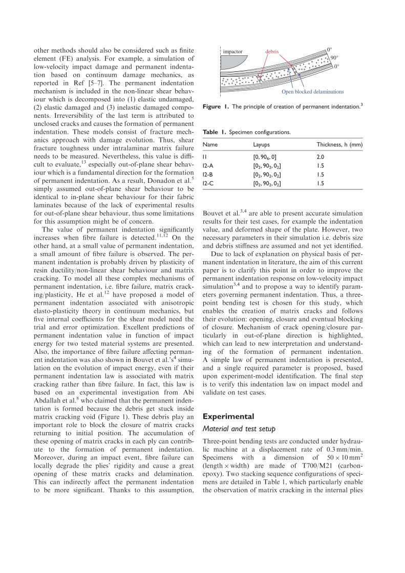
matrix cracking void (Figure 1). These debris play an
important role to block the closure of matrix cracks
returning to initial position. The accumulation of
these opening of matrix cracks in each ply can contrib-
ute to the formation of permanent indentation.
Moreover, during an impact event, fibre failure can
locally degrade the plies’ rigidity and cause a great
opening of these matrix cracks and delamination.
This can indirectly affect the permanent indentation
to be more significant. Thanks to this assumption,
Bouvet et al.3,4 are able to present accurate simulation
results for their test cases, for example the indentation
value, and deformed shape of the plate. However, two
necessary parameters in their simulation i.e. debris size
and debris stiffness are assumed and not yet identified.
Due to lack of explanation on physical basis of per-
manent indentation in literature, the aim of this current
paper is to clarify this point in order to improve the
permanent indentation response on low-velocity impact
simulation3,4 and to propose a way to identify param-
eters governing permanent indentation. Thus, a three-
point bending test is chosen for this study, which
enables the creation of matrix cracks and follows
their evolution: opening, closure and eventual blocking
of closure. Mechanism of crack opening/closure par-
ticularly in out-of-plane direction is highlighted,
which can lead to new interpretation and understand-
ing of the formation of permanent indentation.
A simple law of permanent indentation is presented,
and a single required parameter is proposed, based
upon experiment-model identification. The final step
is to verify this indentation law on impact model and
validate on test cases.
Experimental
Material and test setup
Three-point bending tests are conducted under hydrau-
lic machine at a displacement rate of 0.3mm/min.
Specimens with a dimension of 50� 10mm2
(length�width) are made of T700/M21 (carbon-
epoxy). Two stacking sequence configurations of speci-
mens are detailed in Table 1, which particularly enable
the observation of matrix cracking in the internal plies
0°
90°
0° impactor debris
Open blocked delaminations
Figure 1. The principle of creation of permanent indentation.3
Table 1. Specimen configurations.
Name Layups Thickness, h (mm)
I1 [0, 906, 0] 2.0
I2-A [02, 902, 02] 1.5
I2-B [02, 902, 02] 1.5
I2-C [02, 902, 02] 1.5
oriented at 90�. To predominantly generate the matrix
cracking at the 90� plies (generally coupling with
delamination) due to shear with less possibility to
have tensile or compressive fibre failure of 0� external
plies, the span (distance between the two lower sup-
ports) to thickness ratio (L/h) should be reduced.14
Thus, 10mm of span and three cylinder supports of
6mm of diameter are chosen for this study (Figure 2).
During the three-point bending test, a digital camera
with macro lens meanwhile captures in the section of
specimen being affected with an automatic interval
timer function. These images are then post-analysed
using image correlation technique in order to observe
the translation of deformed specimens and their cracks.
Since the physical basis of the mechanism of permanent
indentation is initially assumed due to the debris which
may block the crack closure,8 crack void and debris
should be observed in optical microscope. Therefore,
each specimen must be polished before test to ensure
that the debris observed does not come from small par-
ticles during polish process (generally done after test).
Moreover, areas of interest are photographed by scan-
ning electron microscope (SEM) in order to observe
more precisely the debris.
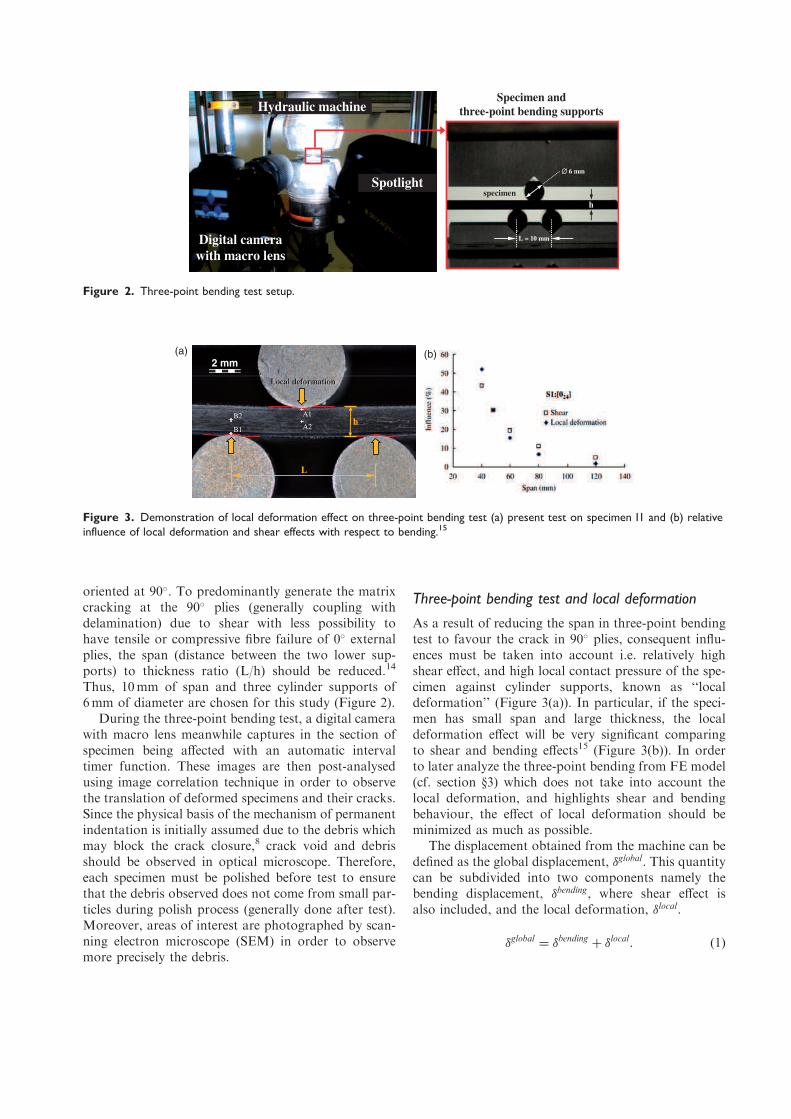
Three-point bending test and local deformation
As a result of reducing the span in three-point bending
test to favour the crack in 90� plies, consequent influ-
ences must be taken into account i.e. relatively high
shear effect, and high local contact pressure of the spe-
cimen against cylinder supports, known as ‘‘local
deformation’’ (Figure 3(a)). In particular, if the speci-
men has small span and large thickness, the local
deformation effect will be very significant comparing
to shear and bending effects15 (Figure 3(b)). In order
to later analyze the three-point bending from FE model
(cf. section §3) which does not take into account the
local deformation, and highlights shear and bending
behaviour, the effect of local deformation should be
minimized as much as possible.
The displacement obtained from the machine can be
defined as the global displacement, �global. This quantity
can be subdivided into two components namely the
bending displacement, �bending, where shear effect is
also included, and the local deformation, �local.
�global ¼ �bending þ �local: ð1Þ
(a) (b)2 mm
Local deformation Local deformation
B1
L
h B2 A1
A2
Figure 3. Demonstration of local deformation effect on three-point bending test (a) present test on specimen I1 and (b) relative
influence of local deformation and shear effects with respect to bending.15
Spotlight
Digital camera
with macro lens
Hydraulic machine Specimen and
three-point bending supports
L = 10 mm
specimen
∅ 6 mm
h
Figure 2. Three-point bending test setup.

The bending displacement cannot directly be mea-
sured but it can be evaluated if the global displacement
and the local deformation are known (equation 1).
Thanks to the image correlation technique in 2D, the
global displacement can be determined by monitoring
the movement on the cylinder supports. Also, the local
deformation can be simply evaluated by measuring the
different displacement between cylinder contact noses
and neutral axis of the specimen, at points A1, A2, B1
and B2, as shown in Figure 3(a).
�local ¼ �A1 ÿ�A2j j þ �B1 ÿ�B2j j ð2Þ
where �A1, �A2, �B1 and �B2 are the vertical displace-
ments at point A1, A2, B1 and B2, respectively. The
software then interprets the difference from the series
of images and gives the results of displacements in
pixel units; these displacements can consequently be
converted to mm. Nevertheless, the acquisition frequen-
cies for global displacement – obtained from hydraulic
machine – and for image correlation are different. Thus,
the displacement measures from image correlation are
fitted by a cubic polynomial interpolation (Figure 4(a)).
Lastly, the bending displacement is obtained, as shown
in Figure 4(b). Hereafter in this paper, unless otherwise
specified, the term ‘‘displacement’’ means the bending
displacement rather than the global displacement.
Opening and closure of matrix crack
The evolution of crack opening/closure is studied
according to previous observation of formation of per-
manent indentation proposed by Abi Abdallah et al.8
Similarly to what occurs in an impact event including a
loading and a rebound, three-point bending test is car-
ried out with only one cycle of loading and unloading.
Many tests were performed, but unfortunately, it is
quite complex to control the formation of a unique
crack in the specimen, to avoid uncertain crack loca-
tion, or even to avoid fibre rupture under the indentor.
Only specimens with a single crack and no fibre rupture
were analysed, so that only the influence of matrix
cracks could be studied. Finally, only four interesting
specimens are chosen. The results from three-point
bending test of specimen I1 are presented in Figure 5.
The specimen is loaded until the appearance of a 45�
matrix cracking (normally coupling with delamination),
which can be noticed due to the dramatic load drop at
state 2–3. When the matrix crack occurs, the specimen’s
internal rigidity suddenly decreased but the global dis-
placement remains the same. As a consequence, the
local deformation is released and leads the bending dis-
placement shift at state 2–3 (see also the displacement
relation in Figure 4(b)). The out-of-plane crack width �zis also measured by using image correlation technique
(same technique as determining the local deformation).
Unloading is then applied and the crack width gets
smaller (state 3-4-5). At the end of the test (point 5),
one can notice that there is a residual crack opening
when the force is null. This phenomenon is assumed
to be the basis of the formation of permanent
indentation.
If this unclosed crack leads to the formation of per-
manent indentation, it is questionable as to what mech-
anisms influence the Residual crack opening width.
Three additional tests on configuration I2 are conse-
quently performed but different load cases are intro-
duced. The load is continuously applied after the onset
of crack initiation and before the presence of fibre failure
to three different levels of added displacements, i.e.
0.02mm, 0.08mm and 0.15mm for specimens I2-A,
I2-B and I2-C, respectively (Figure 6(a)). The results
exhibit some scatters in the onset of crack formation
data for these tests, but different crack widths are inves-
tigated according to the different added displacement
(Figure 6(b)). There is no fixed value of the residual
crack opening, but it probably depends on themaximum
crack opening.
Evolution of crack opening/closure both in trans-
verse direction �t, and in out-of-plane direction �z,
0.0
0.1
0.2
0.3
0.4
0 20 40 60 80 100 1200.00
0.02
0.04
0.06
0.08
0.10
0.12
0.00 0.10 0.20 0.30
Loca
l def
orm
ation (mm
)
Global displacement (mm)
Camera / load ( )
Time (sec)
Displace
men
t (m
m)
Global displacement
(δ global)
Local deformation (δ local)
Bending displacement (δ bending)
(a) (b)
Load ( )
Unload ( )
43
2
2
3
1 )()()( ccccglobalblobalgloballocal +++= δδδδ
432
23
1 )()()( ccccglobalblobalgloballocal +++= δδδδ
Camera / unload ( )
Cubic poly. / load ( )
Cubic poly. / unload ( )
Figure 4. Displacement output data of specimen I1 (a) local deformation in function of global displacement from image correlation
technique and cubic polynomial estimation and (b) different types of displacement during three-point bending test.

0.00
0.02
0.04
0.06
0.08
0.10
0.12
0.0 0.1 0.2 0.3 0.4
I2-A
I2-B
I2-C
0.0
0.4
0.8
1.2
1.6
0.00 0.05 0.10 0.15 0.20 0.25 0.30 0.35 0.40
I2-A
I2-B
I2-C
0.0
0.2
0.4
0.6
0.8
1.0
0.0 0.2 0.4 0.6 0.8 1.0
I1 ( ) I1 ( )
I2-A ( ) I2-A ( )
I2-B ( ) I2-B ( )
I2-C ( ) I2-C ( )
Forc
e (k
N)
Displacement (mm) Displacement (mm)
Crack
open
ing/clo
sure
in z-d
irec
tion (mm
)
(a) (b)+ 0.08 mm
+ 0.15 mm
+ 0.02 mm
Load ( )
Unload ( )
Displacement (non-dimension)
Crack
open
ing/closu
re
(non-d
imen
sion)
(c)
20% - 40%
Load ( )
Unload ( )
z
t l
δ tδ tδ tδ t
δ zδ z
δ zδ z
Figure 6. (a) Force-displacement for tests of specimens I2-A, B and C; (b) crack opening/closure for tests of specimens I2-A, B and C
and (c) non-dimensional crack opening/closure for tests of specimens I1, I2-A, B and C.
Cra
ck open
ing/clo
sure
, δz (m
m)
Forc
e (k
N)
0.00
0.40
0.80
1.20
1.60
0.00 0.05 0.10 0.15 0.20 0.25
0.00
0.02
0.04
0.06
0.08
0.10
0.12
0.00 0.05 0.10 0.15 0.20 0.25
Displacement (mm)
Displacement (mm)
1 2
3
4
5
1
2
3
4
5 5
4
3
2
1load
unload
load unload
2 mm
z
t l
δz
δt
Figure 5. Observation of the evolution of crack opening/closure on the right part of specimen I1.
is determined at the centre of the matrix crack in the
thickness direction of the specimen; the subscripts t and
z denote transverse and out-of-plane directions,
respectively, as demonstrated in Figure 5. The results
of non-dimensional crack evolution, i.e. �t=�maxt and
�z=�maxz , reveal a sensible convergence for all tests.
That is, using non-dimensional values of imposed dis-
placement and crack closure, the shape of crack clo-
sure-displacement curves for all tests are similar, and
regardless of how big the maximum crack opening is,
the final crack closure returns to around 20%–40% of
maximum crack opening (Figure 6(c)) for both crack
directions (t- and z-directions) and for both specimen
configurations.
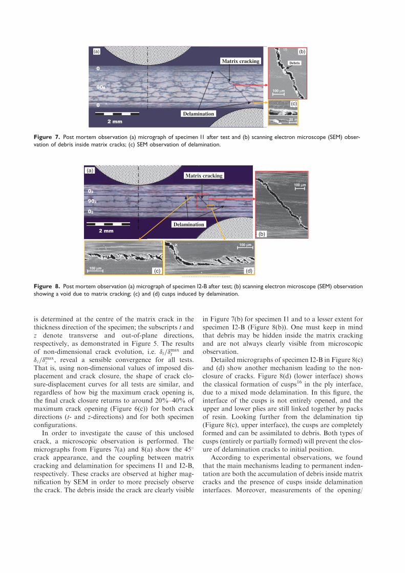
In order to investigate the cause of this unclosed
crack, a microscopic observation is performed. The
micrographs from Figures 7(a) and 8(a) show the 45�
crack appearance, and the coupling between matrix
cracking and delamination for specimens I1 and I2-B,
respectively. These cracks are observed at higher mag-
nification by SEM in order to more precisely observe
the crack. The debris inside the crack are clearly visible
in Figure 7(b) for specimen I1 and to a lesser extent for
specimen I2-B (Figure 8(b)). One must keep in mind
that debris may be hidden inside the matrix cracking
and are not always clearly visible from microscopic
observation.
Detailed micrographs of specimen I2-B in Figure 8(c)
and (d) show another mechanism leading to the non-
closure of cracks. Figure 8(d) (lower interface) shows
the classical formation of cusps16 in the ply interface,
due to a mixed mode delamination. In this figure, the
interface of the cusps is not entirely opened, and the
upper and lower plies are still linked together by packs
of resin. Looking further from the delamination tip
(Figure 8(c), upper interface), the cusps are completely
formed and can be assimilated to debris. Both types of
cusps (entirely or partially formed) will prevent the clos-
ure of delamination cracks to initial position.
According to experimental observations, we found
that the main mechanisms leading to permanent inden-
tation are both the accumulation of debris inside matrix
cracks and the presence of cusps inside delamination
interfaces. Moreover, measurements of the opening/
2 mm
Matrix cracking
Delamination
902
02
02
(d)
100 µm
100 µm
(a)
(b)
100 µm (c)
Figure 8. Post mortem observation (a) micrograph of specimen I2-B after test; (b) scanning electron microscope (SEM) observation
showing a void due to matrix cracking; (c) and (d) cusps induced by delamination.
2 mm
Matrix cracking
906
0
0
Delamination
Debris
(a)
(c)
(b)
20 m
100 µm
Figure 7. Post mortem observation (a) micrograph of specimen I1 after test and (b) scanning electron microscope (SEM) obser-
vation of debris inside matrix cracks; (c) SEM observation of delamination.
closure of cracks show that the final crack width
depends on the maximum width reached during open-
ing of the crack in the test.
Modelling of permanent indentation
Permanent indentation hypothesis
Experiments in the proceeding section demonstrate
that, under unloading, different microscopic mechan-
isms in matrix cracks (debris) and delamination inter-
faces (debris, cusps) result in a global phenomenon of
non-closure of the matrix cracks. From a meso-scale
point of view, the final matrix crack width is found
proportional to the maximum crack width reached
during the test. It leads to the definition of the crack
closure coefficient �, expressed as follows:
�0 ¼ � � �max ð3:1Þ
with
�max �ð Þ ¼ max��t
� �ð Þð Þ ð3:2Þ
where �0 is the final crack width, after unload, and �max
is the maximum crack width ever reached during the
crack opening. t and � are respectively the total time
and the current time. The relation in equation (3.1) is a
fundamental relation to drive the formation of perman-
ent indentation, called ‘‘pseudo-plasticity’’ model. This
law physically comprises both the blocking of debris
and resin plasticity in plies. It can independently be
rewritten for each crack direction: transverse and out-
of-plane, without taking into account the compressive
transversal direction.
�0t ¼ �t � �maxt if �t � 0 ð4:1Þ
�0z ¼�z � �
maxz if �z � 0
�z � �minz if �z 5 0
�
ð4:2Þ
where the �0t , �0z are the final crack-closure width in
transversal and out-of-plane directions, respectively.
Furthermore, the crack closure coefficient from both
directions in this study is assumed to be identical
(�t ¼ �z) due to the fact that the matrix cracks are at
an angle close to 45�, which is confirmed by the results
shown in Figure 6(c).
The crack evolutions are physically observed in
micro-scale in terms of debris and formation of cusps,
but the proposed law (equations 4.1–4.2) is responded
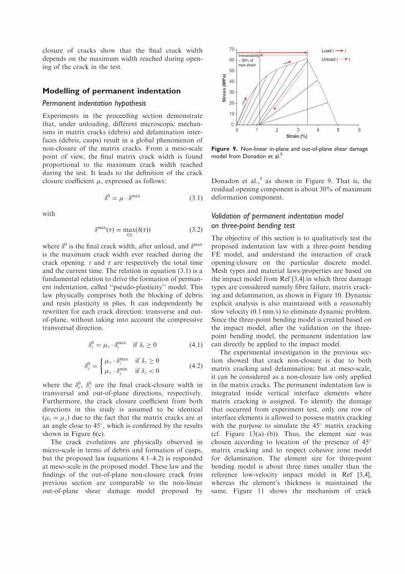
at meso-scale in the proposed model. These law and the
findings of the out-of-plane non-closure crack from
previous section are comparable to the non-linear
out-of-plane shear damage model proposed by
Donadon et al.,5 as shown in Figure 9. That is, the
residual opening component is about 30% of maximum
deformation component.
Validation of permanent indentation model
on three-point bending test
The objective of this section is to qualitatively test the
proposed indentation law with a three-point bending
FE model, and understand the interaction of crack
opening/closure on the particular discrete model.
Mesh types and material laws/properties are based on
the impact model from Ref [3,4] in which three damage
types are considered namely fibre failure, matrix crack-
ing and delamination, as shown in Figure 10. Dynamic
explicit analysis is also maintained with a reasonably
slow velocity (0.1mm/s) to eliminate dynamic problem.
Since the three-point bending model is created based on
the impact model, after the validation on the three-
point bending model, the permanent indentation law
can directly be applied to the impact model.
The experimental investigation in the previous sec-
tion showed that crack non-closure is due to both
matrix cracking and delamination; but at meso-scale,
it can be considered as a non-closure law only applied
in the matrix cracks. The permanent indentation law is
integrated inside vertical interface elements where
matrix cracking is assigned. To identify the damage
that occurred from experiment test, only one row of
interface elements is allowed to possess matrix cracking
with the purpose to simulate the 45� matrix cracking
(cf. Figure 13(a)–(b)). Thus, the element size was
chosen according to location of the presence of 45�
matrix cracking and to respect cohesive zone model
for delamination. The element size for three-point
bending model is about three times smaller than the
reference low-velocity impact model in Ref [3,4],
whereas the element’s thickness is maintained the
same. Figure 11 shows the mechanism of crack
Load ( )
Unload ( ) Irreversibility
≈ 30% of max.strain
Figure 9. Non-linear in-plane and out-of-plane shear damage
model from Donadon et al.5
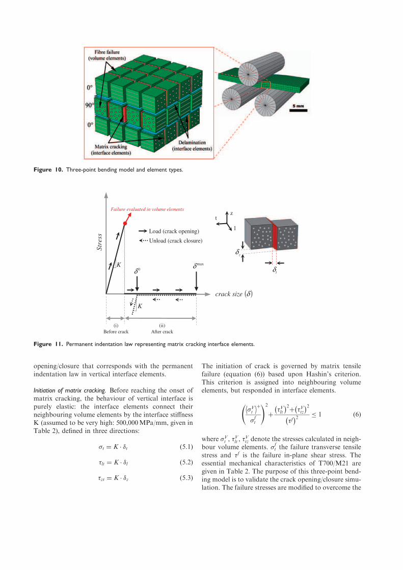
opening/closure that corresponds with the permanent
indentation law in vertical interface elements.
Initiation of matrix cracking. Before reaching the onset of
matrix cracking, the behaviour of vertical interface is
purely elastic: the interface elements connect their
neighbouring volume elements by the interface stiffness
K (assumed to be very high: 500,000MPa/mm, given in
Table 2), defined in three directions:
�t ¼ K � �t ð5:1Þ
�lt ¼ K � �l ð5:2Þ
�zt ¼ K � �z ð5:3Þ
The initiation of crack is governed by matrix tensile
failure (equation (6)) based upon Hashin’s criterion.
This criterion is assigned into neighbouring volume
elements, but responded in interface elements.
�Vt
�þ
�ft
!2
þ�Vltÿ �2
þ �Vtzÿ �2
�fÿ �2
� 1 ð6Þ
where �Vt , �
Vlt , �
Vtz denote the stresses calculated in neigh-
bour volume elements. �ft the failure transverse tensile
stress and �f is the failure in-plane shear stress. The
essential mechanical characteristics of T700/M21 are
given in Table 2. The purpose of this three-point bend-
ing model is to validate the crack opening/closure simu-
lation. The failure stresses are modified to overcome the
Ktδ
zδ
maxδ
K
( )δsizecrack
0δ
(i)
Before crack
Str
ess
Load (crack opening)
Unload (crack closure)
t
l
z Failure evaluated in volume elements
(ii)
After crack
Figure 11. Permanent indentation law representing matrix cracking interface elements.
Figure 10. Three-point bending model and element types.

possible dispersion of rupture value in experimental
tests, so that the cracks can appear at the same time
for both experiment and simulation. For example, the
values of �ft and �f, for material T700/M21,17 which
equal to 60 MPa and 110 MPa, respectively (Table 2),
are replaced by 39MPa and 78MPa for modelling case
of I2-B. Moreover, another reason of the modified fail-
ure stresses is that the three-point bending model has
very thick finite elements comparing to the total thick-
ness. As a result, the estimation of shear distribution in
through-thickness direction is inaccurate and compli-
cated to predict18; but this problem is not evident for
the reference impact model in Ref [3,4] because of a
relatively thin volume element comparing to the lamin-
ate thickness. However, a modification of reducing
element’s thickness or adding number of element was
not made in order to keep the similarity to impact
model and the objective of parameter’s identification.
Opening and closure of cracks. Once the matrix cracking
criterion in volume elements (equation (6)) is reached
(the initiation of crack), the adjacent interface elements
lose their rigidity, their stresses in three directions turn
to zero and the crack instantaneously opens (not taking
into account the energy for propagation). Also, the
delamination is automatically linked, which is per-
formed by a conventional criterion of fracture mech-
anics on the horizontal interface elements. Then,
after initiation of crack, the crack opening is only gov-
erned by delamination, as far as the crack width is
increasing.
When the crack tends to close, during unloading, the
crack closure law – presented in Figure 11 – is applied
only at the interface elements for matrix cracking. As
long as the crack width is larger than the final crack
closure widths, �0t and �0z , expressed previously, the
crack freely closes with no resistant stress. But if the
crack closure goes below these thresholds, the rigidity
will be applied to prevent the crack closure in the z- and
t- directions. The implementation of the crack closure
law can be given as:
�t ¼0 if �t 4 �0t
K � �t ÿ �0tÿ �
if �t � �0t
(
ð7:1Þ
�lt ¼ 0 ð7:2Þ
�zt ¼0 if �zj j4 �0z
�
�
�
�
K � �z ÿ �0zÿ �
if �zj j � �0z
�
�
�
�
(
ð7:3Þ
with �0t and �0z obtained in equations (4.1) and (4.2). The
finding from all experiment tests in Figure 6(c) shows
the final crack width is about 20%–40% of the max-
imum crack opening. Therefore, an average value of
30% is taken as average crack closure coefficient, that
is, �t ¼ �z ¼ 0:3.
The validation of model of three-point bending is
done for all four test cases and gives similar agreement;
but only the case I2-B is presented here because its con-
figuration is similar to the one of impact layup. Since
the failure stresses are set to break as same as in experi-
ment, good onset of load drop is automatically
found, as presented in force-displacement curves in
Figure 12(a), even if its magnitude is overestimated.
This overestimation is due to delamination, that is,
the end of lower interface delamination in experiment
stops at about the lower support’s contact
(Figure 13(b)), whilst the simulated delamination goes
further, as represented by the damage variable in
Figure 13(a). The ratio of the energy release rate to
the critical energy release rate between two modes
(GI=GIc and GII=GIIc) is considered, we found that
this overestimation is predominated due to shear
mode (mode II), which is supposed due to:
– In practice, at the contact between the supports
and specimen there is relatively high compressive
pressure affecting inside laminate, therefore GIIc
should be increased to reduce the delamination
effect in mode II19; but this influence is not
taken into account in the present model.
– The friction effect at the interface for delamin-
ation7 has not been included in model.
The displacement is continued after the onset of crack
formation and the maximum crack opening (�maxt and
�maxz ) is correctly predicted (Figure 12(b)). During
unloading, the numerical results also exhibit a good
accordance in returning of crack width to 30%
Table 2. Mechanical characteristics of T700/M21 unidirectional
ply for the three-point bending model.17
Ply density 1600 kg/m3
Ply thickness 0.25mm
Etenl Tensile Young’s modulus
in fibre direction
130GPa
Ecompl Compressive Young’s modulus
in fibre direction
100GPa
Et Transverse Young’s modulus 7.7GPa
Glt Shear modulus 4.8GPa
�lt Poisson’s ratio 0.33
�ft Tensile failure stress in
transverse direction
60
�f In-plane shear failure stress 110
K Interface element stiffness
of matrix cracking
500000MPa/mm
� Crack closure coefficient 0.3
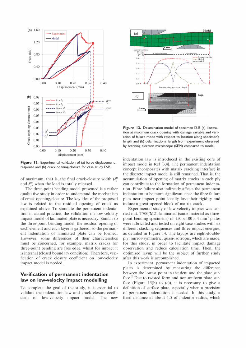
of maximum, that is, the final crack-closure width (�0tand �0z) when the load is totally released.
The three-point bending model presented is a rather
qualitative study in order to understand the mechanism
of crack opening/closure. The key idea of the proposed
law is related to the residual opening of crack as
explained above. To simulate the permanent indenta-
tion in actual practice, the validation on low-velocity
impact model of laminated plate is necessary. Similar to
the three-point bending model, the residual opening of
each element and each layer is gathered, so the perman-
ent indentation of laminated plate can be formed.
However, some differences of their characteristics
must be concerned, for example, matrix cracks for
three-point bending are free edge, whilst for impact it
is internal (closed boundary condition). Therefore, veri-
fication of crack closure coefficient on low-velocity
impact model is needed.
Verification of permanent indentation
law on low-velocity impact modelling
To complete the goal of the study, it is essential to
validate the indentation law and crack closure coeffi-
cient on low-velocity impact model. The new
indentation law is introduced in the existing core of
impact model in Ref [3,4]. The permanent indentation
concept incorporates with matrix cracking interface in
the discrete impact model is still remained. That is, the
accumulation of opening of matrix cracks in each ply
can contribute to the formation of permanent indenta-
tion. Fibre failure also indirectly affects the permanent
indentation to be more significant since the fibre failure
plies near impact point locally lose their rigidity and
induce a great opened block of matrix crack.
Experimental study of low-velocity impact was car-
ried out. T700/M21 laminated (same material as three-
point bending specimens) of 150� 100� 4 mm3 plates
were fabricated and tested on eight case studies with six
different stacking sequences and three impact energies,
as detailed in Figure 14. The layups are eight-double-
ply, mirror-symmetric, quasi-isotropic, which are made,
for this study, in order to facilitate impact damage
observation and reduce calculation time. Then, the
optimized layup will be the subject of further study
after this work is accomplished.
In experiment, permanent indentation of impacted
plates is determined by measuring the difference
between the lowest point in the dent and the plate sur-
face.2 Due to twisted form and non-uniform plate sur-
face (Figure 15(b) to (c)), it is necessary to give a
definition of surface plate, especially when a precision
of permanent indentation is needed. In this study, a
fixed distance at about 1.5 of indentor radius, which
0.00
0.40
0.80
1.20
1.60
0.00
0.01
0.02
0.03
0.04
0.05
0.06
0.07
0.08
0.00 0.10 0.20 0.30 0.40
0.00 0.10 0.20 0.30 0.40
Exp -u
Exp -v
Model -u
Model -v
max
tδ
max
zδ
0
tδ0
zδ
Force (k
N)
Displacement (mm)
Displacement (mm)
Crack
open
ing-closu
re (mm)
Model
Experiment
(a)
(b)δ t
δ t
δ z
δ z
Figure 12. Experimental validation of (a) force-displacement
response and (b) crack opening/closure for case study I2-B.
0.0
0.2
0.4
0.6
0.8
1.0
11 12 13 14 15 16 17 18 19 20
IIcII GG /IcI GG /
Location along specimen’s length
1. Upper interface 2. Lower interface
Delamination
1 mm
Exp. (b)
(a)
1 mm
Model
Delamination
1. 2.
Damage variable
Mode Imode II
Damage variable
Figure 13. Delamination model of specimen I2-B (a) illustra-
tion at maximum crack opening with damage variable and vari-
ation of failure mode with respect to location along specimen’s
length and (b) delamination’s length from experiment observed
by scanning electron microscope (SEM) compared to model.

is approximately around the dent, is selected to be a
representation of average plate surface. Then, perman-
ent indentation can be measured by image correlation
technique in 3D.
In order to validate the permanent indentation law,
a parametric study of the crack closure coefficient (�),
the single required parameter, was carried out.
Figure 14 gives the indentation results of eight test
cases which is a comparison between the experiments
and the simulations. The influence of tuning the crack
closure coefficient is shown, that is, this parameter dir-
ectly affects the permanent indentation. The parameters
�t ¼ �z ¼ 0:35 instead of 0.30 from previous section
were found to obtain good agreement between experi-
ments and simulations on variation of stacking
sequence and impact energy. The different error of
the worst case is 24%, which seems acceptable since
experimental indentation may be uncertain due to e.g.
the scattering of experimental data,12 relaxation of per-
manent indentation after 48 hours8 or the method of
measurement as mentioned above. However, the ten-
dency of permanent indentation is well captured.
The result of example case E2 [-452, 452, 02, 902]s at
25 J is showed in Figure 15, demonstrating that the
proposed law is able to predict:
. Value and shape of permanent indentation on
impacted side (Figure 15(a)–(c)).
. Ply-splitting on non-impacted side due to matrix
cracking is simulated, as shown in Figure 15(d)–(e)
and No.10–No.100 in Figure 16, in spite of an over-
estimation of the simulation (red zone in Figure
15(e)).
. This law also allows the shape of the deformed plate
after impact to be obtained as shown by the twisted
shape (Figure 15(b)–(e)). The law also allows the
creation of residual opening of delamination,
according to the interaction with other failure
modes, as can be seen from the micrograph in
Figure 16(a)–(b). The same sub-numbers indicate
the similarity between experiment and simulation
at the particular locations.
Although the overestimation of opened delamination
in the middle of the layup has been found
(Figure 16(b)), it does have small effect on the per-
manent indentation on impacted side since the per-
manent indentation is due to the gathering of
residual openings of three or four plies on the
impacted side as shown in Figure 16(b).
One can notice that the middle of the layup E2 is [02,
904, 02], which is similar to the layup of specimens from
three-point bending test I1 [0, 906, 0] or I2 [02, 902, 02].
The 45� matrix cracking at locations 2, 3 coupling with
delamination at locations 6, 7 in Figure 16(a) from
0
0.1
0.2
0.3
0.4
0.5
C1
C2
D1
D2
E1
E2
E2
E2
Experim
ent
Model = 0.35
Model = 0.30
30J
17J
25J
Lay
ups/ impac
t en
ergy
[02,90
2,45
2,-45
2] s
[90
2,0
2,-45
2,45
2] s [4
52,0
2,-45
2,90
2] s
[-45
2,90
2,45
2,0
2] s
[45
2,-45
2,90
2,0
2] s
[-45
2,45
2,0
2,90
2] s
[-45
2,45
2,0
2,90
2] s
[-45
2,45
2,0
2,90
2] s
Permanent indentation
(mm)
µ µ
Figure
14.Comparisonofpermanentindentationoneighttest
cases,varyinglayupsandimpactenergies.

impact test seems comparable to micrographs
from three-point bending tests in Figure 7(a) or
Figure 8(a). This can confirm that the choice of using
three-point bending test to characterize permanent
indentation is reasonable.
Assigning the non-closure crack law into only matrix
cracking interfaces is able to contribute not only to the
permanent indentation but also the residual opening of
delamination. On the contrary, as the present model
allows the coupling between matrix cracking and
delamination, giving the non-closure crack law at
delamination interfaces also seems realistic.
The local plasticity under the indentor is also
important for the permanent indentation especially
for thick laminates. This topic is currently in progress
and will shortly be combined to the global impact
model. Thus, the crack closure coefficient may be
later adjusted. This point must be studied further.
Conclusion
In the presented paper, a model of permanent indenta-
tion due to low-velocity impact was proposed using
three-point bending test. An experimental observation
of matrix crack opening/closure leads to the idea of
permanent indentation formation. When a matrix
crack appears, it usually does not completely close
and does remain at approximately 30% of maximum
crack opening, observed in both transversal and out-of-
plane directions. This unclosed crack is due to the
blocking of debris inside matrix cracking and cusp for-
mation due to mixed mode (peel and shear) delamin-
ation. By taking into account both findings, a simple
material law of indentation was proposed according to
the unclosed crack which is defined by the crack closure
coefficient.
The pseudo-plasticity law was initially tested with
three-point bending model based upon a selected case
study (I2-B) with the aim of understanding how the
crack opening/closure mechanism interacts to the dis-
crete model. Consequently, the same law was validated
on low-velocity impact model, and the crack closure
coefficient was found to directly affect the value of per-
manent indentation.
Advantages of the proposed law are its simplicity,
and need of only a single parameter which can be found
from numerically adjusting the parameter. Also, this
law can predict deformed shape of impacted plate
0.0
0.1
0.2
0.3
0.4
0 15 30 45 60 75 90 105 120 135 150
Exp
Model
Impacted side
Experiment
Perman
ent inden
tation (mm)
Location along specimen’s length(mm)
Permanent indentation
Permanent indentation
cut A-A cut A-A
cut A-A (exp.)
cut A-A (model)
Reference for indentation measurement
(∼1.5R impactor from impact point)
0 mm
0.4 mm
Perman
ent inden
tation
Impacted side
Non-impacted side
0°
90°
100 mm
Model
(a)
(d) (e) Non-impacted side
0 mm
1.0 mm
(b) (c)
Ply-splitting
100 mm
Figure 15. Comparison of permanent indentation for impact test case E2 [ÿ452, 452, 02, 902]s at 25 J.

Figure
16.Comparisonoflongitudinalsectioncutcrossingimpactpointafterimpactforimpacttest
case
E2[-452,452,02,902] sat
25J(a)micrographfrom
experiment;(b)
simulation.
such as twisted form, or opened block of delamination.
This benefit is essential for CAI simulation in next step
when buckling failure is partially due to plate deflec-
tion. On the other hand, it still has some limitations, for
example, at high-impact energy with large permanent
indentation or penetration, the indentation is mainly
governed by the fibre failure, and thus supplementary
criterion must be added. However, if the objective is to
numerically optimize composite structure at BVID,
approximately 0.3mm–0.6mm of dent depth,1 the pro-
posed hypothesis is justified.
Acknowledgements
This work was granted access to the HPC resources of
CALMIP under the allocation 2012-P1026.
Funding
The authors gratefully acknowledge the partial financial sup-
port through the THEOS Operation Training Program
(TOTP).
Conflict of Interest
None declared.
References
1. Rouchon J. Fatigue and damage tolerance aspects for
composite aircraft structures. Delft1995.
2. ASTM D7136/D7136M. Standard test method for measur-
ing the damage resistance of a fiber-reinforced polymer
matrix composite to a drop-weight impact event, 2007.
3. Bouvet C, Rivallant S and Barrau J-J. Low velocity impact
modeling in composite laminates capturing permanent
indentation. Compos Sci Technol 2012; 72: 1977–1988.
4. Bouvet C, Hongkarnjanakul N, Rivallant S, et al. Discrete
impact modeling of inter- and intra-laminar failure in com-
posites. In: Abrate S, Castanie B and Rajapakse YDS (eds)
Dynamic failure of composite and sandwich structures.
Netherlands: Springer, 2013, pp.339–392.
5. Donadon MV, Iannucci L, Falzon BG, et al. A progressive
failure model for composite laminates subjected to low
velocity impact damage. Compos Struct 2008; 86:
1232–1252.
6. Faggiani A and Falzon BG. Predicting low-velocity impact
damage on a stiffened composite panel. Compos Part A:
Appl Sci Manuf 2010; 41: 737–749.
7. Shi Y, Swait T and Soutis C. Modelling damage evolu-
tion in composite laminates subjected to low velocity
impact. Compos Struct 2012; 94: 2902–2913.
8. Abi Abdallah E, Bouvet C, Rivallant S, et al.
Experimental analysis of damage creation and permanent
indentation on highly oriented plates. Compos Sci
Technol 2009; 69: 1238–1245.
9. Caprino G and Lopresto V. The significance of indenta-
tion in the inspection of carbon fibre-reinforced plastic
panels damaged by low-velocity impact. Compos Sci
Technol 2000; 60: 1003–1012.
10. Caprino G, Langella A and Lopresto V. Indentation and
penetration of carbon fibre reinforced plastic laminates.
Compos Part B: Eng 2003; 34: 319–325.
11. Chen P, Shen Z, Xiong J, et al. Failure mechanisms of
laminated composites subjected to static indentation.
Compos Struct 2006; 75: 489–495.
12. He W, Guan Z, Li X, et al. Prediction of permanent
indentation due to impact on laminated composites
based on an elasto-plastic model incorporating fiber fail-
ure. Compos Struct 2013; 96: 232–242.
13. Laffan MJ, Pinho ST, Robinson P, et al. Measurement of
the fracture toughness associated with the longitudinal
fibre compressive failure mode of laminated composites.
Compos Part A: Appl Sci Manuf 2012; 43: 1930–1938.
14. Carbajal N and Mujika F. Determination of compressive
strength of unidirectional composites by three-point
bending tests. Polym Test 2009; 28: 150–156.
15. Mujika F. On the effect of shear and local deformation in
three-point bending tests. Polym Test 2007; 26: 869–877.
16. Brain WS. Fractography for continuous fiber composites.
In: Engineered materials handbook Vol.1: Composites.
ASM International, 1987.
17. Prombut P. Caracterisation de la propagation de delami-
nage des stratifies composites multidirectionnels. PhD
Thesis, Universite de Toulouse, Toulouse, 2007.
18. Cho YB and Averill RC. An improved theory and finite-
element model for laminated composite and sandwich
beams using first-order zig-zag sublaminate approxima-
tions. Compos Struct 1997; 37: 281–298.
19. Li X, Hallett SR and Wisnom MR. Predicting the effect
of through-thickness compressive stress on delamination
using interface elements. Compos Part A: Appl Sci Manuf
2008; 39: 218–230.