low fidelity and high fidelity structural models - … · tutor: prof. carrera e. phd zappino e....
TRANSCRIPT

Tutor: Prof. Carrera E. Phd Zappino E. Phd Petrolo M. Torino 11-12 October 2017
Low Fidelity and High Fidelity Structural Models for
Metallic and Composites Aircraft Structures
Andrea Viglietti Dottorato in Ingegneria Meccanica
XXX Ciclo Cluster TIVANO
Tutor Aziendali: Ing. Giglioli R. Ing. Candela F.
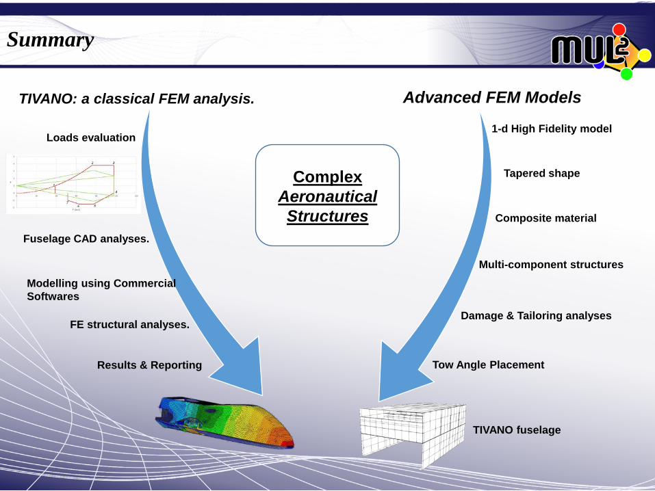
Summary
Loads evaluation
Fuselage CAD analyses.
FE structural analyses.
Modelling using Commercial Softwares
Results & Reporting
TIVANO: a classical FEM analysis. Advanced FEM Models
1-d High Fidelity model
Tapered shape
Composite material
Complex Aeronautical Structures
Multi-component structures
Damage & Tailoring analyses
Tow Angle Placement
TIVANO fuselage

TIVANO
DIRITTI RISERVATI - © COPYRIGHT
Leonardo S.p.A.
I contenuti di questo documento sono Proprietà Intellettuale di Leonardo. Qualsiasi copia o diffusione di questo documento è proibita in qualsivoglia forma senza autorizzazione scritta Leonardo.
Unless otherwise specified, the contents of this document are the intellectual property of Leonardo. Any copying or communication of this document in any form is forbidden without the written authorization from Leonardo.

Work Flow
DIRITTI RISERVATI - © COPYRIGHT
Leonardo S.p.A.
I contenuti di questo documento sono Proprietà Intellettuale di Leonardo. Qualsiasi copia o diffusione di questo documento è proibita in qualsivoglia forma senza autorizzazione scritta Leonardo.
Unless otherwise specified, the contents of this document are the intellectual property of Leonardo. Any copying or communication of this document in any form is forbidden without the written authorization from Leonardo.
Preliminary load evaluation.
CAD analysis: Geometry cleaning process
and optimization for the FEM modelling.
Import to pre-processing software and preliminary
mesh of the structure components.
Introduction of the loads, BCs, materials and layup.
Definitive mesh.
Design and modification of the structure
Model Checks: free edges, free body check,
rigid modes…
Static analysis Inertial analysis
Optimization of the structure considering the obtained
results (thickness, reinforcments…).
Reporting
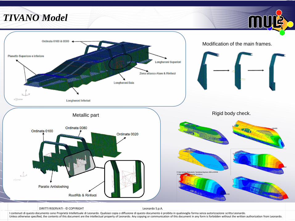
TIVANO Model
DIRITTI RISERVATI - © COPYRIGHT
Leonardo S.p.A.
I contenuti di questo documento sono Proprietà Intellettuale di Leonardo. Qualsiasi copia o diffusione di questo documento è proibita in qualsivoglia forma senza autorizzazione scritta Leonardo.
Unless otherwise specified, the contents of this document are the intellectual property of Leonardo. Any copying or communication of this document in any form is forbidden without the written authorization from Leonardo.
Modification of the main frames.
Rigid body check. Metallic part
DIRITTI RISERVATI - © COPYRIGHT
Leonardo S.p.A.
I contenuti di questo documento sono Proprietà Intellettuale di Leonardo. Qualsiasi copia o diffusione di questo documento è proibita in qualsivoglia forma senza autorizzazione scritta Leonardo.
Unless otherwise specified, the contents of this document are the intellectual property of Leonardo. Any copying or communication of this document in any form is forbidden without the written authorization from Leonardo.
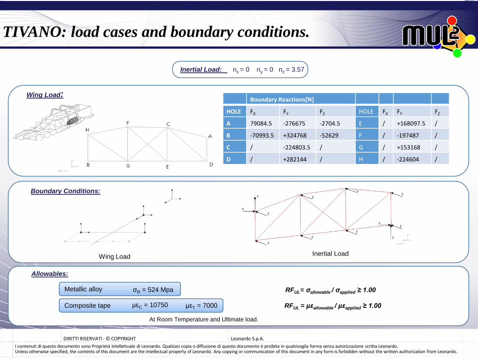
Inertial Load: nx = 0 ny = 0 nz = 3.57
Boundary Reactions[N]
HOLE FX FY FZ HOLE FX FY FZ
A 79084.5 -276675 -2704.5 E / +168097.5 /
B -70993.5 +324768 -52629 F / -197487 /
C / -224803.5 / G / +153168 /
D / +282144 / H / -224604 /
Wing Load:
Boundary Conditions:
Wing Load Inertial Load
TIVANO: load cases and boundary conditions.
Allowables:
Metallic alloy σR = 524 Mpa
Composite tape µεC = 10750 µεT = 7000
At Room Temperature and Ultimate load.
RFUL = µεallowable / µεapplied ≥ 1.00
RFUL= σallowable / σapplied ≥ 1.00

TIVANO: Inertial Load Results
DIRITTI RISERVATI - © COPYRIGHT
Leonardo S.p.A.
I contenuti di questo documento sono Proprietà Intellettuale di Leonardo. Qualsiasi copia o diffusione di questo documento è proibita in qualsivoglia forma senza autorizzazione scritta Leonardo.
Unless otherwise specified, the contents of this document are the intellectual property of Leonardo. Any copying or communication of this document in any form is forbidden without the written authorization from Leonardo.
Figure: Maximum traction strain.
RF= 524 / 49.6 > 10
Figure: Maximum stress.
RFc = 7000/1070 > 6
RFT = 10750/1330 > 8
Figure: Displacements of the fuselage.

TIVANO: Wing Load Results
DIRITTI RISERVATI - © COPYRIGHT
Leonardo S.p.A.
I contenuti di questo documento sono Proprietà Intellettuale di Leonardo. Qualsiasi copia o diffusione di questo documento è proibita in qualsivoglia forma senza autorizzazione scritta Leonardo.
Unless otherwise specified, the contents of this document are the intellectual property of Leonardo. Any copying or communication of this document in any form is forbidden without the written authorization from Leonardo.
Componente: RF Componente: RF Skin Ordinate A trazione HIGH A trazione HIGH A compressione HIGH A compressione 3.2 Longheroni Superiori Ordinata 125 A trazione 3.1 A trazione 3.38 A compressione HIGH A compressione 3.91 Longheroni Inferiori Pianetto Superiore A trazione HIGH A trazione HIGH A compressione HIGH A compressione 2.6 Longheroni Baia Pianetto Inferiore A trazione 3.02 A trazione 2.78 A compressione 3.55 A compressione 3.55
RF= 524 / 496 = 1.06
Figure: Maximum stress.
Table: Reserve factors of the components.
Figure: Displacements of the fuselage.
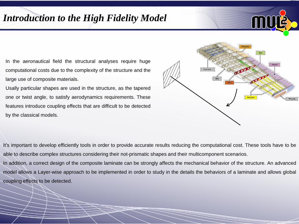
Introduction to the High Fidelity Model
In the aeronautical field the structural analyses require huge
computational costs due to the complexity of the structure and the
large use of composite materials.
Usally particular shapes are used in the structure, as the tapered
one or twist angle, to satisfy aerodynamics requirements. These
features introduce coupling effects that are difficult to be detected
by the classical models.
It’s important to develop efficiently tools in order to provide accurate results reducing the computational cost. These tools have to be
able to describe complex structures considering their not-prismatic shapes and their multicomponent scenarios.
In addition, a correct design of the composite laminate can be strongly affects the mechanical behavior of the structure. An advanced
model allows a Layer-wise approach to be implemented in order to study in the details the behaviors of a laminate and allows global
coupling effects to be detected.

Preliminaries and material definition
Figure: Frames.
Figure: Material coordinate frames.
δLint = ∫V δεT σ dV
δLine = ∫V δuT ρü dV
K
M
u(x,y,z)=Ni(y)Fτ(x,z)qτi
u(x,y,z)=Fτ(x,z)u(y)
Figure: Cross-section described by L9 elements.
Static & Free Vibration Problems
δLint = δqsj ∫V Fs(x,z)Nj(y)[ bT ][ C ][ b ] Ni(y)Fτ(x,z)dV qτi
[3x6] [6x6] [6x3]
[3x3]
Fundamental Nucleus [kτsij]
ε(x,y,z) = bu(x,y,z) δε(x,y,z) = bNj(y)Fs(x,z)δqsj
σ(x,y,z) = Cε (x,y,z) σ(x,y,z) = CbNi(y)Fτ(x,z)q τi
Ĉ= TCTT
Derivation of the kτsij :

Assembling of different beams & tapered shapes.
Different structures with LE expansion can be assembled very
easily because in this formulation there are only pure
displacements. In this way the structures can be joined without
incurring in issues.
The assembling can be done by imposing the congruence of
the displacements.
Beam Elements
Lagrange Node Shared Node
Component-wise Approach.
Component wise approach

To the complex structure using the Component Wise approach...

F
F
Figure: σzy over the height of the panel. Figure: σzy over the lenght of the panel.
Table: Displacements.
Table: Displacements.
Figure: σzy over the height of the panel. Figure: σzy over the lenght of the panel.
Static analyses

Three spar panel made of composite laminate
ELL
ELL
Layer-wise description
Figure: Modal shape comparison between the models.
Table: Frequencies. Figure: First 10 Modal Shapes.

The damage is implemented by the degradation of the mechanical material proprieties.
The damage level is defined through the parameter d, according to the formula. Ed = d x E 0 < d < 1
Figure: Displacements of the central stringer. Figure: σzy of the central stringer.
Introduction of the damage.
Once a component fails, the load is redistributed on the other structural elements. The understanding of the evolution of the stress
distribution inside the structure is of primary importance in the design process and for the maintenance program
F
In the aeronautical field, due to the complexity of the structure and the particular shapes to ensure the aerodynamic characteristics, the
evaluation of the stress evolution is very difficult. For these reasons the timely damage detection is a crucial point in the maintenance
process. Through the comparison of the damaged natural frequencies with a wide damage database which collects the information about the
damage and the natural frequencies, an estimation of the damage location can be performed. In this way the efficiency of the damage
detection tests can be increased.

CUF for the damage detection.
Whole damaged components Damaged layer Local Damage
Local Damage Maps
Each local damage produces a well-defined decrease of the frequency. Detection maps can be drawn for maintenance pourpuse.
d=0,1

d=0,9 d=0,5 d=0,1
CUF for the damage detection: the damaged stringer case.

CUF for the damage detection: the complex wing-box.
Figure: Beam description of the components. Figure: Damaged Cases.
Figure: alteration of the modal shapes at the tip of the wing box.
Table: Frequencies.
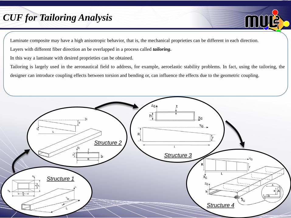
CUF for Tailoring Analysis
Structure 1
Structure 2
Structure 3
Structure 4
Laminate composite may have a high anisotropic behavior, that is, the mechanical proprieties can be different in each direction.
Layers with different fiber direction an be overlapped in a process called tailoring.
In this way a laminate with desired proprieties can be obtained.
Tailoring is largely used in the aeronautical field to address, for example, aeroelastic stability problems. In fact, using the tailoring, the
designer can introduce coupling effects between torsion and bending or, can influence the effects due to the geometric coupling.

Tailoring analysis: structure 1 and structure 2.
Structure 1 Structure 2
Table: Lamination
90°/0° 60°/-30° 45°/-45°

Tailoring analysis: structure 3.
Case 1
Case 2
Alteration of the modal shapes at the tip (Case 1).
Mode 1 Mode 3
Mode 1 Mode 2 Mode 3

Tailoring analysis: structure 3.
Mode 1 Mode 2
Mode 3 Mode 4
Table: Particular Cases
Mode 1: the behavior is governed by the stiffness of the panel. Mode 2: the behavior is influenced by both the webs and the panels. The highest frequencies are obtained with a cross play lamination in the components. Mode 3: As the first mode. The tailoring of the web have yet weak effects. Mode 4: The torsional modes is maximized by an angle play configuration.

Tow Angle Placement
Mode 1 Mode 2 Mode 3
kτsij = ∫V Fs(x,z)Nj(y)[ bT ][ C ][ b ] Ni(y)Fτ(x,z)dV
C is function of (x,y,z) and have to be integrated.
θ(y) = 0 + (y/L)*90
Tow angle LE model: the material proprieties are integrated.
LE model: lamination law discretized by step. Each beam element introduces a step of the lamination.
VSCL Variable stiffness composite laminate: a laminate can be developed providing different stiffness according to
the considered area through a variable lamination over the structure.

Tow Angle Placement: 3-layer assessment
Reference: Akhavan H., Ribeiro P.. «Natural modes of vibration of variable stiffness composite laminates with curvilinear fibers» COMPOSITE STRUCTURE, Vol.93, pp.3040-3047, 2011.
θ = 2(T2-T1)|x|/a + T1
Mode 1 Mode 2
45/90/-45 Lamination.
Tow angle Lamination.
Final Remarks
These activities have led me to compare different methods to model an aeronautical structure exploring the characteristics of each method.
Through the training on the job, the company work flow has been learned overcoming the different difficulties that may arise. The structure of a complex fuselage has been analyzed using commercial software. It has been optimized in order to be able to deal with the wing loads.
A CUF 1-D model based on the Lagrange expansion is extended for the analyses of complex structure characterized by tapered shapes and multicomponent scenarios using a Component-Wise approach. The results confirm that the present model can deal with this topic providing accurate 3D-like results comparable with those obtained from an expensive analysis performed with a commercial code.
A deeply damage analyses are performed on different aeronautical structure for damage detection purpose. Simple tapered structure and complex wing box are investigated. The model is able to detect the effects on the frequencies and on the modal shapes due to local and global damages. The following notes can be listed:
• Low damage can introduce effects only on the high frequencies. For this reason, a model for the damage detection has to be able to detect with accuracy a wide range of frequencies.
• The natural frequency analyses must be performed considering both the frequencies and the modal shapes. In fact, damage can affect some frequencies and not the related mode. The opposite is also possible.
• In a wing structure, a damage can influence the bending-torsional coupling effects. It's important to evaluate if the new condition is suitable in term of aerodynamic and aeroelasticity. Thanks to its efficiency and accuracy, the model can be used to create a database of multiple damage scenarios which can be useful for maintenance reasons and damage detection.
Tapered shapes and sweep angle have been implemented in several complex structures for tailoring analyses. The torsional-bending couplings and the possible alterations induced by the tailoring process is also investigated. Using particular laminations, the frequencies can be shifted to the suitable values without modifying the geometry and the coupling effects can be emphasized or reduced. These feature can be of great interest in the aeroelastic design of wing structures.
The model is extended to deal with TOW placement problem. Results confirm the capability to describe a structure with the fiber direction governed by a control law. In this way the structure can be designed with a variable stiffness. Problems of VSCL (Variable Stiffness Composite Laminate) are investigated providing very good results. This technology is of great interest for the control of the coupling effects and the aeroelastic behavior without affect the stiffness in other areas of a wing box (for example the root of the wing).