steps to feasibility for laminar wing...
TRANSCRIPT

1
Abstract Within an automated multidisciplinary framework involving aerodynamics and structural mechanics, a structural design process is built that leads to a composite wing enabling natural laminar flow (NLF). At earlier investigations a simplified approach to represent the structural design concept was used to obtain fast results. On the other hand realistic wing designs are much more complex. In order to obtain more realistic results in aircraft pre-design the influence of various fidelity levels of structural sizing are investigated on a forward swept wing and the results are compared regarding wing mass and stiffness.
1 Introduction Seitz et al. [4] and Kruse et al. [5] have shown that for a given flight task an aircraft configuration with forward swept wing with a T-Tailplane and rear mounted engines has advantages in fuel consumption against conventional aircraft designs. Natural laminar flow is attested at cruise flight condition for the given airfoils. In this previous investigation a simplified method for structural sizing was used without taking local stability into account. An enhanced structural optimization tool has been developed to automate the sizing process and consider stringers with their effects to local and global deformations.
Especially the twist distribution and the wing weight are responsible for the aerodynamic performance and fuel burn. Due to high correlations between structural
deformations, aerodynamic loads and fuel burn efficiency a multidisciplinary optimization (MDO) process is necessary to consider all relevant effects in the design process.
Besides the aerodynamic efficiency the structural performance is important for the resulting weight and fuel burn efficiency. Different panel design concepts and different failure criteria can be addressed, which have consequences in resulting weight and deformations.
1.1 Surrounding MDO-Process To achieve natural laminar flow during cruise flight conditions, a concept for a multidisciplinary optimization process has been developed. Mainly the coupling between aerodynamic and structural mechanics is addressed.
With a fluid-structure coupled simulation a feasible design for a given aerodynamic shape can be achieved. During the coupling high fidelity aerodynamic calculations deliver accurate flight loads for the structural sizing and an also high fidelity sizing ensures correct corresponding deformations and weight predictions. Within the loosely coupled process, several load cases can be handled.
After the coupled calculations an inverse aerodynamic shape optimization is provided, where a target pressure distribution enhance the aerodynamic performance. Thereby a new aerodynamic profile is given and again calculations with fluid-structure interaction are applied.
STEPS TO FEASIBILITY FOR LAMINAR WING DESIGN IN A MULTIDISCIPLINARY ENVIRONMENT
Sascha Dähne*, Tobias Bach*, Dr. Christian Hühne*
* German Aerospace Center (DLR), Institute of Composite Structures and Adaptive Systems
Keywords: MDO, Composite, Sizing Criteria, NLF, Feasible Design

S. DAEHNE, T. BACH
2
Subsequently a performance calculation with laminar-turbulent transition prediction for the design point and several off-design points is included to evaluate the found design.
1.2 Common Parametric Aircraft Description The common baseline for all disciplines involved in the process is the “Common Parametric Aircraft Configuration Scheme” CPACS. Inside the CPACS file, which is xml-based, all relevant information about an aircraft can be stored. For wings information about the aerodynamic profiles including their global arrangement are available. In addition to the outer aerodynamic contour information about structural elements like the position and orientation of spars, ribs and stringers and their design concept and used materials are stored. Also storable are information about load cases, flight missions or costs.
By using a common description for all disciplines a consistency of the disciplinary models concerning geometry and stiffness is ensured. An additional advantage is the reduction of interfaces between tools in the MDO process. Using the CPACS file only one interface per tool has to be developed: reading the CPACS file and writing the results back. Tools between different disciplines are not necessary any more.
2 Structural Optimization Module
The aim of the structural sizing and optimization process is the minimization of the structural weight Wstruct with respect to a set of failure criteria, where all Margins of Safety (MoS) must be above MoSrequired:
Min Wstruct w.r.t. Failure Criteria MoS ≥ MoSrequired
(1)
The embedding of the developed sizing and optimization module in the global process is shown in Fig. 1.
Based on the CPACS file a Finite Element Model (FE-Model) of the wing is automatically generated. Implemented in the model generator are logics for the discretization of the wing: wing cover and spars are present in the FE model and can be used as an optimization region as well as each rib. The fidelity of the FE mesh is defined by the user. With the external loads, which are calculated with computational fluid dynamics or aeroelastic calculations and afterwards mapped on the FE model, the internal loads are calculated with linear-static FE calculations. Subsequently the FE model with its geometry, material properties and loads are passed to the sizing and optimization module. Both MSC Nastran and Ansys models are supported.
In the sizing and optimization module the
Fig. 1. Sizing & Optimization in global context; one iteration of global process [2]

3
STEPS TO FEASIBILITY FOR LAMINAR WING DESIGN IN A MULTIDISCIPLINARY ENVIRONMENT
geometry is post processed and components and assemblies are created. A component for example is a panel of a wing cover, confined by two ribs, front and rear spar, or a section of a spar or a rib. In an assembly all components of the same part like the wing upper cover or the front spar are composed. Each component is an optimization region.
In a second step a design concept is assigned to each component. By considering the design concept only in the sizing and optimization module it is possible to investigate different design concepts with the same FE model because stringers are only considered explicitly during component sizing. As a result the creation of the FE model is simplified because the stringer stiffness is smeared into the overall panel ABD-matrix and the stringers must not be modelled with discrete elements. Furthermore an optimization of stringer profile and pitch is possible with the same model as well.
Also applied to the components are the failure criteria, which serve as constraints for the optimization. Structure mechanical criteria for Strength, Damage Tolerance, Global Buckling, Local Buckling and Crippling are used for the sizing of the components. Furthermore it is possible to consider criteria from manufacturing and operations like
minimum and maximum ply share in 0°/90°+45°/-45° direction, minimum and maximum height for stringer webs or a minimum skin thickness for repair.
The component sizing itself is performed within a software called HyperSizer [7]. The creation of components and assemblies as well as the assignment of the design concept and the failure criteria is done in HyperSizer. Inside the software an internal object model is created for each component, exemplarily shown in Fig. 2 for a blade-stiffened panel [1].
For each of the design parameters of the component a minimum and maximum boundary is specified by the user. Also specified is the number of discrete values. The parameter can attain between these values. In addition materials are applied to the parts of the panel. The number of the permutation of the component design points creates the number of design candidates for each component. It should be noticed that skin and stringer are always optimized together which is not always the case in other optimization processes [3]. With this approach a change in the stiffness distribution between skin and stringer results in internal stress redistribution so an optimum design can be calculated. The internal stresses are calculated from the distribution of the internal loads coming from the FE calculation and the
Fig. 2. Component Object Model for Blade Stiffened Panel

S. DAEHNE, T. BACH
4
stiffness of the panel objects. To check convergence the mass of the
wing box and the MoS are checked.
Δm=(mi-mi-1)/mi-1 MoS ≥ MoSrequired 2)
The allowed change of mass can be specified by the user. If convergence is achieved the results are exported from the sizing and optimization module and the CPACS file is updated with the results. Otherwise the FE model is updated with the optimization results and new internal loads are calculated. Furthermore the design values in HyperSizer are modified for each component with respect to the components MoS.
3 Parameter Study
3.1 Use Case The design configuration used for the parameter study is a forward swept wing, which has shown his capability for natural laminar flow in previous investigations [4]. The wing is mounted at a short range aircraft which has a T-Tailplane and rear mounted engines.
The wing has a half span of 17.9m and 28 ribs. The spars are located at 15% and 60% relative chord length.
Fig. 3 shows the FE-Model used for the following investigations. Exemplary the upper skin ply distribution is shown. For the other structural parts a similar distribution is used. If stringers are used they have a [60/30/10] material. For the following investigations, the material will not be changed.
The principal stiffness direction of the wing covers has been rotated forward in order to avoid divergence and to tailor the bending and twist behavior of the wing. The laminate stiffness is based on the results of the LamAiR project as can be seen on Fig. 3. This stiffness distribution ensures the desired wash out, which means a negative twist while bending upwards [4], [6].
The resulting principal direction of composite stiffness is a result of shell based calculations where stringers were not considered explicitly. Therefore local stability cannot be proofed. Global stability is ensured by using a factor to increase the component’s property bending stiffness based on realistic stiffener
70/20/10
60/20/20
40/40/20
50/30/20
Fig. 3. LamAiR Configuration with wing cover laminate thickness [mm]
principal stiffness direction

5
STEPS TO FEASIBILITY FOR LAMINAR WING DESIGN IN A MULTIDISCIPLINARY ENVIRONMENT
configurations. Three representative loadcases are used in
the inverstigation: one cruise flight case where laminar flow shall be achived and two loadcases for positive and negative accelarations. The positive loadcase represents a gust situation at +3.44g and the negative one describes the accelleration of -1.0g in nz from the v-n-diagram.
The configuration was found by a coupeled process, where the aerodynamic loads and the deformations due to sized stiffness are in balance.
The loads from the coupled process are used for the present work; no aero-structure coupled calculations were performed again. Only the effects of different fidelity levels are considered.
3.2 Investigated Configurations To investigate the effects of failure criteria the reference wing configuration is sized with different sets of failure criteria. Table 1 shows the different failure criteria sets and the corresponding version name. In version one only strength is applied to the sizing process. Version two adds the global buckling criteria, which prevent skin-buckling in a rib-bay. Stiffeners are added in version three, but only global buckling is valuated. The stiffener spacing is set to 200mm for all optimization regions. The stiffeners are oriented along the principal stiffness direction as described in sec. 3.3. Local buckling phenomena are considered only in version four, where local buckling of stringer webs, skin-buckling between the stringers and also crippling is examined.
Table 1. Version Overview
Refinement in considered Failure Categories and Design Features
Version
1 2 3 4
Strength x x x x Global Buckling x x x Stringer available x x Local Buckling x
In the following paragraph the failure criteria used for the structural optimization are described.
For the strength evaluation a maximum strain criterion is used that evaluates the strain in 1-direction, 2-direction and 12-direction of the component’s laminate. This relatively simple approach is used due to the fact that in a pre-design phase discrete composite layups are not present so a ply-wise strength evaluation is not meaningful. The criterion is used for the skin composites and also for the blade stringer web if present. For global buckling, respectively panel buckling, a Rayleigh-Ritz approach is used. All present panel loads (biaxial compression and shear) are considered as well as a possible curvature.
With version four of the parameter study local buckling and crippling are added to the set of failure criteria. For local buckling skin segments between two stringers and the stringer web are evaluated for biaxial compression and shear in addition to the global buckling criteria. For the stringer a one SFSC (simple-free-simple-clamped) boundary condition is assumed. Stringer crippling is evaluated with the composite crippling method from the MilHdbk 17 [8]; the transition between crippling and buckling is considered with a Johnson-Euler Interaction formula.
For all versions a minimum skin and web thickness of 2mm and a minimum web height of 30mm are applied in order to fulfill repair and manufacturing constrains.
3.3 Principal Stiffness Direction
Aeroelastic tailoring is indispensable for natural laminar flow on a forward swept wing like the reference configuration. The strategy to obtain the desired behavior of bend-twist coupling is to rotate the principal stiffness direction of the skin and stringer materials.
For the present investigation aerodynamic loads are only available for the reference configuration and the corresponding twist deformations. Varying the principal direction leads to a different behavior of twist and bending, while fixing the composite material properties. Furthermore the resulting weight due to the sizing process will change. Until the full coupled process is available preliminary

S. DAEHNE, T. BACH
6
investigations can give an answer about trends based on loads of the reference configuration.
4 Results
4.1 Weight The first result to look at is the resulting wing box mass after the sizing process. Fig. 5 shows the assembly weights in tons as stacked columns over the different fidelity versions. The first step from version one to two leads to a massive increase in overall weight about 67%. While the front and rear spars stay nearly constant, the upper and lower skin panels increase their weight due to the global buckling criteria. This statement can be validated by the constraining failure criteria. Only three out of 135 components are not dimensioned by global buckling.
Adding stringers to the wing upper and lower cover with version three leads to a decrease in overall weight by 30%. The weight reduction is mainly driven by the upper and lower skin while the mass of the rear spar and ribs slightly increases.
Taking local stability into account the upper skin weight is increased by 4%. Thereby the web became lower and thicker, which shifts the moment of inertia to the outside.
4.2 Deformations
Looking at the deformations gives information about the overall stiffness and the goal to avoid
Fig. 6. Relative Bending
0
0.5
1
1.5
2
2.5
3
V1 V2 V3 V4
Component weights [t]
Front spar Rear spar Ribs
Lower skin Upper skin
Fig. 5. Assembly Weights
Fig. 4. Bending
REFERENCE
7
STEPS TO FEASIBILITY FOR LAMINAR WING DESIGN IN A MULTIDISCIPLINARY ENVIRONMENT
static divergence. The bending is shown in Fig. 4. Besides
the reference bending from the LamAiR configuration, the bending lines are plotted for each version over the span. Version two has the
lowest deflection of all versions. When adding stringers the bending stiffness of the whole wing decreases but the weight too, as shown in subsection 4.1.
In Fig. 6, the bending of version one to four is shown relative to bending line of the reference configuration. Version two reduces the bending at the tip about 50% which is paid with an increase in weight of about 67%.
When applying all failure criteria an almost constant reduction in bending about 20% can be observed.
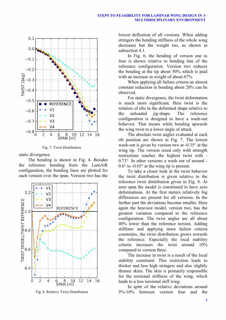
For static divergence, the twist deformation is much more significant. Here twist is the rotation of ribs in the deformed shape relative to the unloaded jig-shape. The reference configuration is designed to have a wash-out behavior. That means while bending upwards the wing twist to a lower angle of attack.
The absolute twist angles evaluated at each rib position are shown in Fig. 7. The lowest wash-out is given by version two at -0.35° at the wing tip. The version sized only with strength restrictions reaches the highest twist with -0.73°. In other versions a wash out of around -0.6° to -0.65° at the wing tip is present.
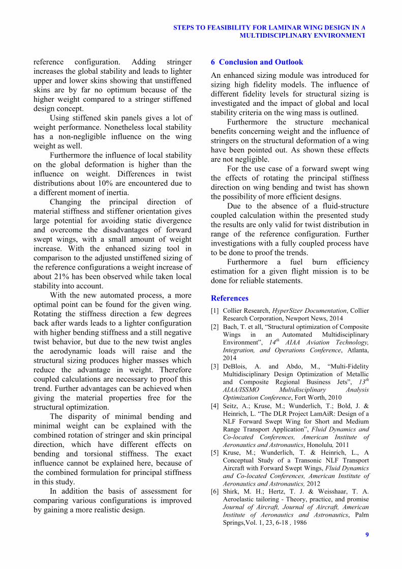
To take a closer look at the twist behavior the twist distribution is given relative to the reference twist distribution given in Fig. 8. At zero span the model is constituted to have zero deformations. At the first meters relatively big differences are present for all versions. In the further part the deviations become smaller. Here again the heaviest model, version two, has the greatest variation compared to the reference configuration. The twist angles are all about 40% lower than the reference torsion. Adding stiffener and applying more failure criteria constrains, the twist distribution grows towards the reference. Especially the local stability criteria increases the twist around 10% compared to version three.
The increase in twist is a result of the local stability constraint. This restriction leads to thicker and less high stringers and also slightly thinner skins. The skin is primarily responsible for the torsional stiffness of the wing, which leads to a less torsional stiff wing.
In spite of the relative deviations around 5%-10% between version four and the
Fig. 7. Twist Distribution
Fig. 8. Relative Twist Distribution
REFERENCE

S. DAEHNE, T. BACH
8
reference, the absolute values are in mean around 0.02°. Such small differences change the corresponding aerodynamic load just in a negligible manner.
4.3 Principal Stiffness Direction Considering the principal direction the material orientation angle rotated around the z-axes. The angle between the reference orientation and the rotated one is called anisotropy angle in the following. A positive angle means that material orientation axes will be rotated more forward in flight and swept direction. Negative angles mean that the principal stiffness direction will be rotated aft wards. The zero degree direction is rotated around 11° forward in relation to the 50% chord line.
The anisotropy angle has been rotated in range of -15° and +20° around the reference direction. Subsequently the model has been sized with all criteria mentioned in version four.
Fig. 9 shows the twist at the tip, the tip bending and the resulting weight after sizing for different anisotropy angles. Around -2° a local minimum is found for the tip bending. A minimal wing bending is analogous to maximum bending stiffness. The tip twist has
another minimum around +3° of principal stiffness direction. Because the minimum of bending and twist stiffnesses are not present at the same anisotropy angle a tradeoff between bending and stiffness is necessary. In addition the weight has yet another minimum around -9°. The twist of the minimal weight has a positive value which means a growing angle of attack. Such a behavior is called wash-in and it increase static divergence tendencies.
The change of tip bending around -10° corresponds with the minimum weight anisotropy angle direction. In this case the stiffeners are orientated along the 50% chord length line. The reference configuration has a disadvantage of around 400 kg in contrast to the minimal achievable weight but reduces the twist angle about -0.9° and switch the wash-in to a wash out behavior.
5 Discussion The resulting weights with different sets of failure criteria cannot be neglected. The increase in weight from an unstiffened wing sized only with strength to an unstiffened wing with global stability constrains shows the dominant influence of stability constrains on the given
Fig. 9. Principal Stiffness Direction
9
STEPS TO FEASIBILITY FOR LAMINAR WING DESIGN IN A MULTIDISCIPLINARY ENVIRONMENT
reference configuration. Adding stringer increases the global stability and leads to lighter upper and lower skins showing that unstiffened skins are by far no optimum because of the higher weight compared to a stringer stiffened design concept.
Using stiffened skin panels gives a lot of weight performance. Nonetheless local stability has a non-negligible influence on the wing weight as well.
Furthermore the influence of local stability on the global deformation is higher than the influence on weight. Differences in twist distributions about 10% are encountered due to a different moment of inertia.
Changing the principal direction of material stiffness and stiffener orientation gives large potential for avoiding static divergence and overcome the disadvantages of forward swept wings, with a small amount of weight increase. With the enhanced sizing tool in comparison to the adjusted unstiffened sizing of the reference configurations a weight increase of about 21% has been observed while taken local stability into account.
With the new automated process, a more optimal point can be found for the given wing. Rotating the stiffness direction a few degrees back after wards leads to a lighter configuration with higher bending stiffness and a still negative twist behavior, but due to the new twist angles the aerodynamic loads will raise and the structural sizing produces higher masses which reduce the advantage in weight. Therefore coupled calculations are necessary to proof this trend. Further advantages can be achieved when giving the material properties free for the structural optimization.
The disparity of minimal bending and minimal weight can be explained with the combined rotation of stringer and skin principal direction, which have different effects on bending and torsional stiffness. The exact influence cannot be explained here, because of the combined formulation for principal stiffness in this study.
In addition the basis of assessment for comparing various configurations is improved by gaining a more realistic design.
6 Conclusion and Outlook An enhanced sizing module was introduced for sizing high fidelity models. The influence of different fidelity levels for structural sizing is investigated and the impact of global and local stability criteria on the wing mass is outlined.
Furthermore the structure mechanical benefits concerning weight and the influence of stringers on the structural deformation of a wing have been pointed out. As shown these effects are not negligible.
For the use case of a forward swept wing the effects of rotating the principal stiffness direction on wing bending and twist has shown the possibility of more efficient designs.
Due to the absence of a fluid-structure coupled calculation within the presented study the results are only valid for twist distribution in range of the reference configuration. Further investigations with a fully coupled process have to be done to proof the trends.
Furthermore a fuel burn efficiency estimation for a given flight mission is to be done for reliable statements.
References [1] Collier Research, HyperSizer Documentation, Collier
Research Corporation, Newport News, 2014 [2] Bach, T. et all, “Structural optimization of Composite
Wings in an Automated Multidisciplinary Environment”, 14th AIAA Aviation Technology, Integration, and Operations Conference, Atlanta, 2014
[3] DeBlois, A. and Abdo, M., “Multi-Fidelity Multidisciplinary Design Optimization of Metallic and Composite Regional Business Jets”, 13th AIAA/ISSMO Multidisciplinary Analysis Optimization Conference, Fort Worth, 2010
[4] Seitz, A.; Kruse, M.; Wunderlich, T.; Bold, J. & Heinrich, L. “The DLR Project LamAiR: Design of a NLF Forward Swept Wing for Short and Medium Range Transport Application”, Fluid Dynamics and Co-located Conferences, American Institute of Aeronautics and Astronautics, Honolulu, 2011
[5] Kruse, M.; Wunderlich, T. & Heinrich, L., A Conceptual Study of a Transonic NLF Transport Aircraft with Forward Swept Wings, Fluid Dynamics and Co-located Conferences, American Institute of Aeronautics and Astronautics, 2012
[6] Shirk, M. H.; Hertz, T. J. & Weisshaar, T. A. Aeroelastic tailoring - Theory, practice, and promise Journal of Aircraft, Journal of Aircraft, American Institute of Aeronautics and Astronautics, Palm Springs,Vol. 1, 23, 6-18 , 1986

S. DAEHNE, T. BACH
10
[7] HyperSizer, Software Package, Ver. 7.0.35, Collier Research Corporation, Newport News, 2014
[8] US Department of Defense, MIL-HDBK-17-3F, Composite Materials Handbook, Volume 3Polymer Matrix Composites Materials Usage, Design and Analysis, 2002
Copyright Statement The authors confirm that they, and/or their company or organization, hold copyright on all of the original material included in this paper. The authors also confirm that they have obtained permission, from the copyright holder of any third party material included in this paper, to publish it as part of their paper. The authors confirm that they give permission, or have obtained permission from the copyright holder of this paper, for the publication and distribution of this paper as part of the ICAS 2014 proceedings or as individual off-prints from the proceedings.