low current switching - cooper industries€¦ · low current switching phenomena • history –...
TRANSCRIPT


LOW CURRENT
SWITCHING
PHENOMENA
By: John M. Makal
Staff Engineer
Nov. 3, 1997
ICC Project 10-46

LOW CURRENTSWITCHING PHENOMENA
• History• Products Involved• Failure Modes & Effects• Common Factors• Testing Experience• Hypothesis on Causes• Possible Solutions
LOW CURRENTSWITCHING PHENOMENA
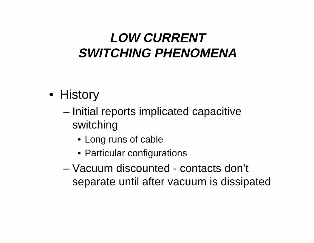
• History– Initial reports implicated capacitive
switching• Long runs of cable• Particular configurations
– Vacuum discounted - contacts don’tseparate until after vacuum is dissipated

LOW CURRENTSWITCHING PHENOMENA
Products Involved:
• All manufacturers products involved• Problem increases as voltage increases• Elbows and caps on inserts and junctions• Problems at all points of system
– Open end of cable– At source end of dead ended cable– Opening loop

LOW CURRENTSWITCHING PHENOMENA
Failure Modes and Effects:
• Interface flashes during separation• Flash self clears or operates system protection• Requires significant downtime to replace inserts
and elbows (flash results in carbon deposition)• Exposes all in area to effects of free arc in air

LOW CURRENTSWITCHING PHENOMENA
Common Factors:
• Occurs prior to contact separation• Low or now current• Tick marks at back end of probe• Occurs on both inserts and junctions• Occurs with insulated and conductive cuffs
LOW CURRENTSWITCHING PHENOMENA
Common Factors:
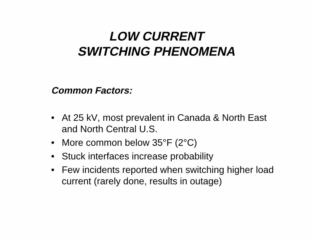
• At 25 kV, most prevalent in Canada & North Eastand North Central U.S.
• More common below 35°F (2°C)• Stuck interfaces increase probability• Few incidents reported when switching higher load
current (rarely done, results in outage)

LOW CURRENTSWITCHING PHENOMENA
TankWall
ContactsOverlapped
Interface is separated
BushingWell Typical
TickLocation

LOW CURRENTSWITCHING PHENOMENA
Test Experience:
• Testing done with Wisconsin Public Service• Dielectric Withstands in Air• Switching elbows/caps with Wisconsin Electric
Power• Pressure Measurements• Library Inputs
LOW CURRENTSWITCHING PHENOMENA
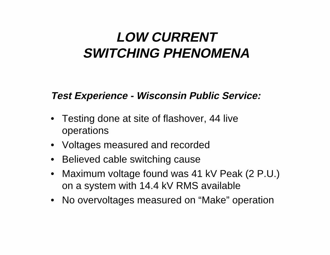
Test Experience - Wisconsin Public Service:
• Testing done at site of flashover, 44 liveoperations
• Voltages measured and recorded• Believed cable switching cause• Maximum voltage found was 41 kV Peak (2 P.U.)
on a system with 14.4 kV RMS available• No overvoltages measured on “Make” operation

LOW CURRENTSWITCHING PHENOMENA
Test Experience - Tests in Air:
• Series of elbows tested in air for voltage withstand• Elbow/bushing interface separated; contacts touch• 25 kV class elbows/bushings withstand 42 kV RMS
(59.4 kV Peak)
LOW CURRENTSWITCHING PHENOMENA
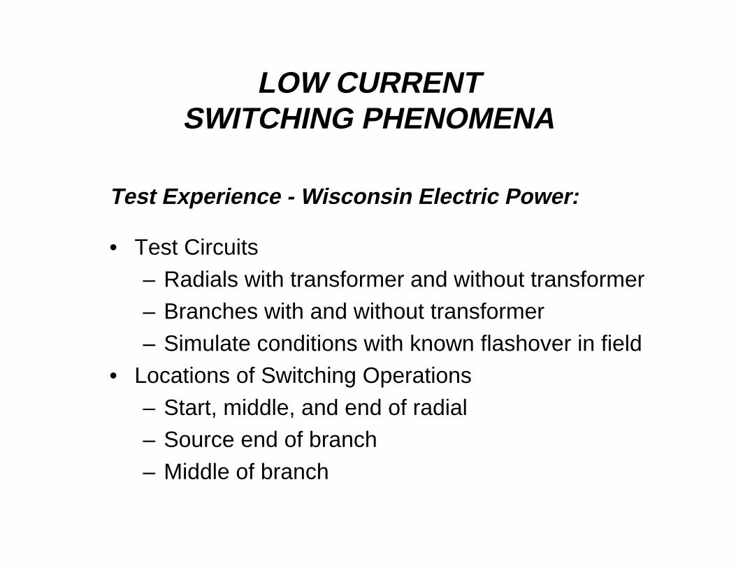
Test Experience - Wisconsin Electric Power:
• Test Circuits– Radials with transformer and without transformer– Branches with and without transformer– Simulate conditions with known flashover in field
• Locations of Switching Operations– Start, middle, and end of radial– Source end of branch– Middle of branch
LOW CURRENTSWITCHING PHENOMENA
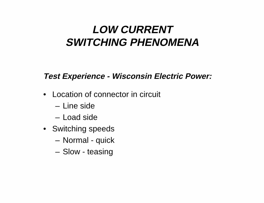
Test Experience - Wisconsin Electric Power:
• Location of connector in circuit– Line side– Load side
• Switching speeds– Normal - quick– Slow - teasing
LOW CURRENTSWITCHING PHENOMENA
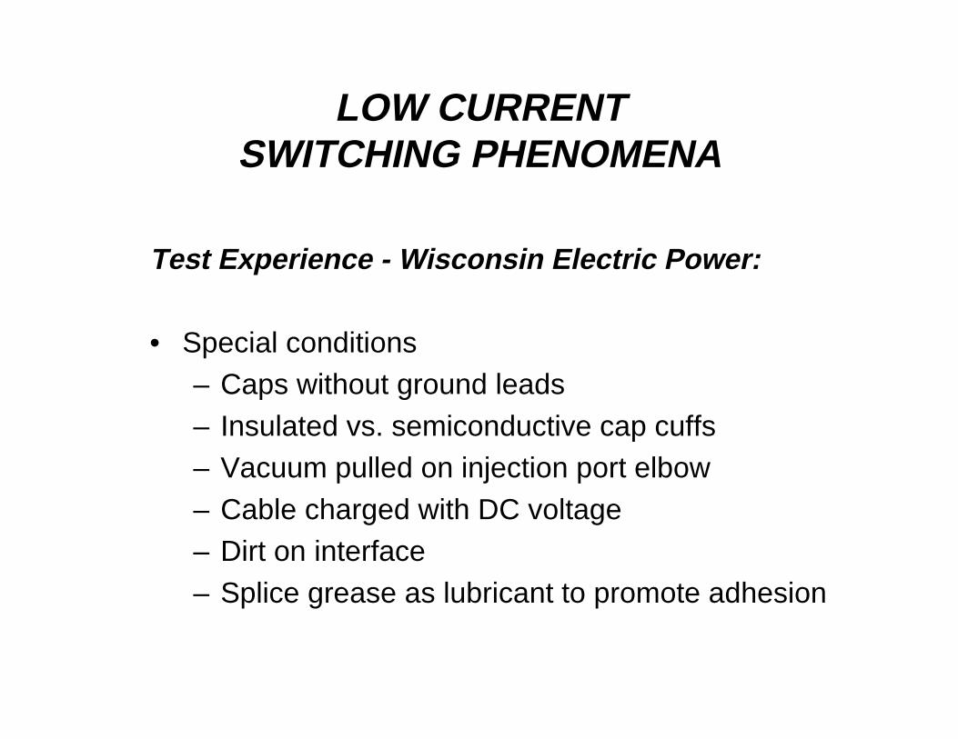
Test Experience - Wisconsin Electric Power:
• Special conditions– Caps without ground leads– Insulated vs. semiconductive cap cuffs– Vacuum pulled on injection port elbow– Cable charged with DC voltage– Dirt on interface– Splice grease as lubricant to promote adhesion
LOW CURRENTSWITCHING PHENOMENA
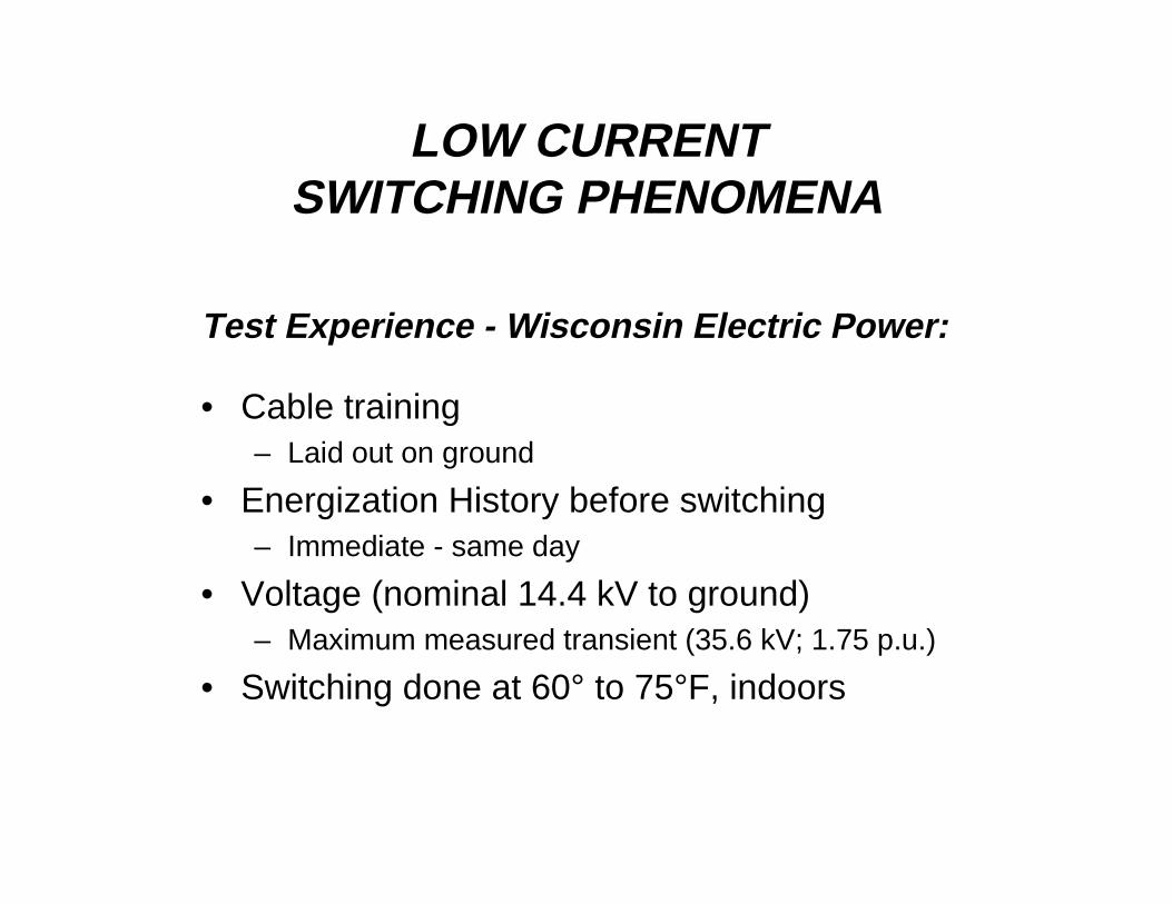
Test Experience - Wisconsin Electric Power:
• Cable training– Laid out on ground
• Energization History before switching– Immediate - same day
• Voltage (nominal 14.4 kV to ground)– Maximum measured transient (35.6 kV; 1.75 p.u.)
• Switching done at 60° to 75°F, indoors

LOW CURRENTSWITCHING PHENOMENA
Test Experience - Wisconsin Electric Power:
• Instrumentation– With and without dividers and recorders– High speed video– Standard VHS video
• Tests done through 11/94


LOW CURRENTSWITCHING PHENOMENA
Test Experience - Wisconsin Electric Power:
• WEPCO provides cable, connections tosystem
• Cooper provides manpower and site
Conditions: Indoors (60 to 75°F); multiple operations onunaged parts

LOW CURRENTSWITCHING PHENOMENA
Test Experience - Wisconsin Electric Power:
• Outdoor Test Circuits– Switching done outside– Parts continuously held at 14.4 kV LG between tests– Cables were left on reels– Tests run with and without instrumentation– Images captured on both high speed and normal VHS
videotape– Tests run on junctions only

LOW CURRENTSWITCHING PHENOMENA
25 kV Low Current Test Circuit
CPS and WEPCO
LOW CURRENTSWITCHING PHENOMENA
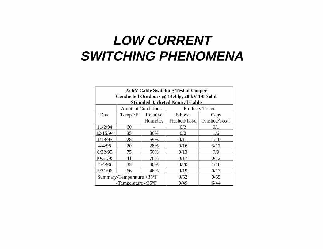
25 kV Cable Switching Test at CooperConducted Outdoors @ 14.4 lg; 28 kV 1/0 Solid
Stranded Jacketed Neutral CableAmbient Conditions Products Tested
Date Temp-°F RelativeHumidity
ElbowsFlashed/Total
CapsFlashed/Total
11/2/94 60 - 0/3 0/112/15/94 35 86% 0/2 1/61/18/95 28 69% 0/11 1/104/4/95 20 28% 0/16 3/128/22/95 75 60% 0/13 0/910/31/95 41 78% 0/17 0/124/4/96 33 86% 0/20 1/165/31/96 66 46% 0/19 0/13Summary-Temperature >35°F -Temperature ≤35°F
0/520/49
0/556/44

INSERT SCAN
LOW CURRENTSWITCHING PHENOMENA
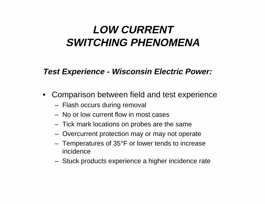
Test Experience - Wisconsin Electric Power:
• Comparison between field and test experience– Flash occurs during removal– No or low current flow in most cases– Tick mark locations on probes are the same– Overcurrent protection may or may not operate– Temperatures of 35°F or lower tends to increase
incidence– Stuck products experience a higher incidence rate

LOW CURRENTSWITCHING PHENOMENA
Test Experience - Pressure Measurements:
• Earlier tests show a reduction in pressure occurringduring separation; discounted because switchingdoes not start until after vacuum is dissipated
• Wish to know what level of vacuum occurs aselbows separate from mating bushings

LOW CURRENTSWITCHING PHENOMENA
Pressure Measurement - Test Modifications
LOW CURRENTSWITCHING PHENOMENA
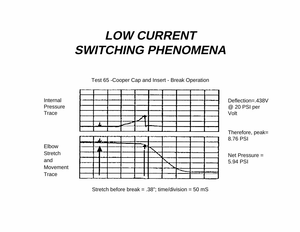
Test 65 -Cooper Cap and Insert - Break Operation
InternalPressureTrace
ElbowStretchandMovementTrace
Deflection=.438V@ 20 PSI perVolt
Therefore, peak=8.76 PSI
Net Pressure =5.94 PSI
Stretch before break = .38”; time/division = 50 mS

LOW CURRENTSWITCHING PHENOMENA
0-1.4 1.5-2.9
3.0-4.4
4.5-5.9
6.0-7.4
7.5-8.9
9.0-10.4
10.5-11.9
12.0-13.4
13.5-15.0
0
5
10
15
20
25
CO
UN
T I
N R
AN
GE
0-1.4 1.5-2.9
3.0-4.4
4.5-5.9
6.0-7.4
7.5-8.9
9.0-10.4
10.5-11.9
12.0-13.4
13.5-15.0
RESIDUAL PRESSURE ps iaVacuum Atmosphere

LOW CURRENTSWITCHING PHENOMENA
LOW CURRENTSWITCHING PHENOMENA
Primary Failure Mode:
• Flashover along the 200A interface,immediately after separation of theinterfaces. This will occur even before thecontacts separate!
• Occurs before actual switching begins.
LOW CURRENTSWITCHING PHENOMENA
Hypothesis
• During separation, a partial vacuum iscreated, reducing the air pressure in theinterface region. This reduced pressurelowers the dielectric strength along theinterface, increasing the probability of aflashover, as system transients increasethe stress.

LOW CURRENTSWITCHING PHENOMENA
Hypothesis comments:
• There are two probabilistic inputs:– The pressure/dielectric withstand
– The peak voltage occurring in thesystem

LOW CURRENTSWITCHING PHENOMENA
Voltage withstand vs. pressure during elbow separation
NOTE: 59 kV isminimum withstandkV measured in airat 20°C and 1atmosphere
Typical PeakVoltage Measured
Typical PressuresMeasured

LOW CURRENTSWITCHING PHENOMENA
Possible solution areas:
• Keep product same size/fit with existing bushings• Heat elbows before operating (WEPCO experience)• Maintain fresh lubrication• Eliminate vacuum• Increase creepage• Increase dielectric withstand base level

LOW CURRENTSWITCHING PHENOMENA
Insert Scan

THE SOLUTION TO
LOW CURRENT SWITCHING
FLASHOVER PROBLEMS
By: John M. Makal
Staff Engineer
Nov. 4, 1997
ICC Project 10-50

THE SOLUTION TO
LOW CURRENT SWITCHING
FLASHOVER PROBLEMS
25 kV 200A Loadbreak Connectors
The Problem
Primary Cause
The Solution
* Insulated Insert & Probe
Switching Test Protocol
Test Results
Field Trials
Features & Benefits

25 kV 200A LOADBREAK
“ENHANCED SWITCHING”
PROBLEM:
• Line-to-ground flashover when removing elbowsand caps on lightly loaded or no load circuits.

PARTIAL VACUUMFLASHOVER PATH

25 kV 200A LOADBREAK
“ENHANCED SWITCHING”
PRODUCTS INVOLVED:
• Elbows and Caps• Bushing Inserts, Junctions and Feedthru
Insert• All manufacturers• All combinations
25 kV 200A LOADBREAK
“ENHANCED SWITCHING”
CONTRIBUTING FACTORS:
• Temperature below 40°F (5°C)• Stuck or seized• Low or no load current• High altitude

Voltage withstand versus Altitude at Various Temperatures (°C)
Based on relationship - Air density = Air Density Original * Exp^-0.00018*Altitude inmeters, and Paschen’s Law

25 kV 200A LOADBREAK
“ENHANCED SWITCHING”
PARTIAL VACUUM EFFECT
Action:• Pulling elbow creates partial vacuum
Reaction:• Reduction in dielectric breakdown level of air along
interface
Physics:• Per Paschen’s Law

INTERNAL AIR SPACEINSIDE ELBOW
25 kV 200A LOADBREAK
“ENHANCED SWITCHING”
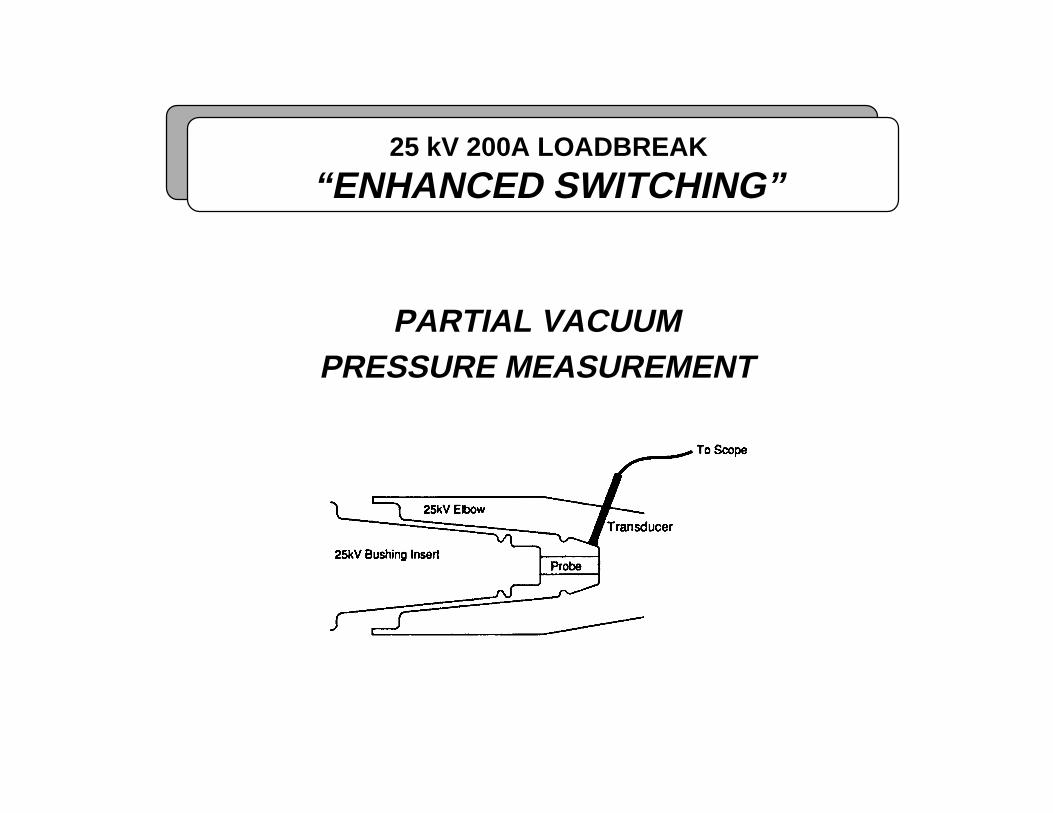
PARTIAL VACUUMPRESSURE MEASUREMENT

PASCHEN’S LAW
25 kV 200A LOADBREAK
“ENHANCED SWITCHING”
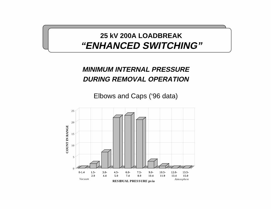
MINIMUM INTERNAL PRESSUREDURING REMOVAL OPERATION
Elbows and Caps (‘96 data)
0-1.4 1.5-2.9
3.0-4.4
4.5-5.9
6.0-7.4
7.5-8.9
9.0-10.4
10.5-11.9
12.0-13.4
13.5-15.0
0
5
10
15
20
25
CO
UN
T I
N R
AN
GE
0-1.4 1.5-2.9
3.0-4.4
4.5-5.9
6.0-7.4
7.5-8.9
9.0-10.4
10.5-11.9
12.0-13.4
13.5-15.0
RESIDUAL PRESSURE ps iaVacuum Atmosphere
25 kV 200A LOADBREAK
“ENHANCED SWITCHING”
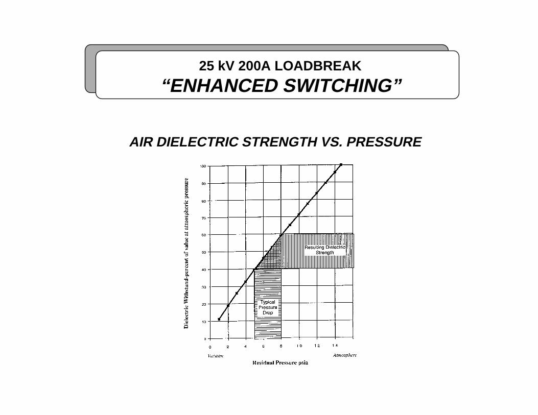
AIR DIELECTRIC STRENGTH VS. PRESSURE
25 kV 200A LOADBREAK
“ENHANCED SWITCHING”
PRIMARY CAUSE:
• Reduction of dielectric strength along interfacedue to creation of partial vacuum while pullingoff elbow or cap (Paschen’s Law).
25 kV 200A LOADBREAK
“ENHANCED SWITCHING”
‘96 PROPOSALINCREASED VOLUME INSERT
WHAT:• Increase Air Volume of Semiconductive Insert
WHY:• Reduces Partial Vacuum• Increases Dielectric Breakdown Level
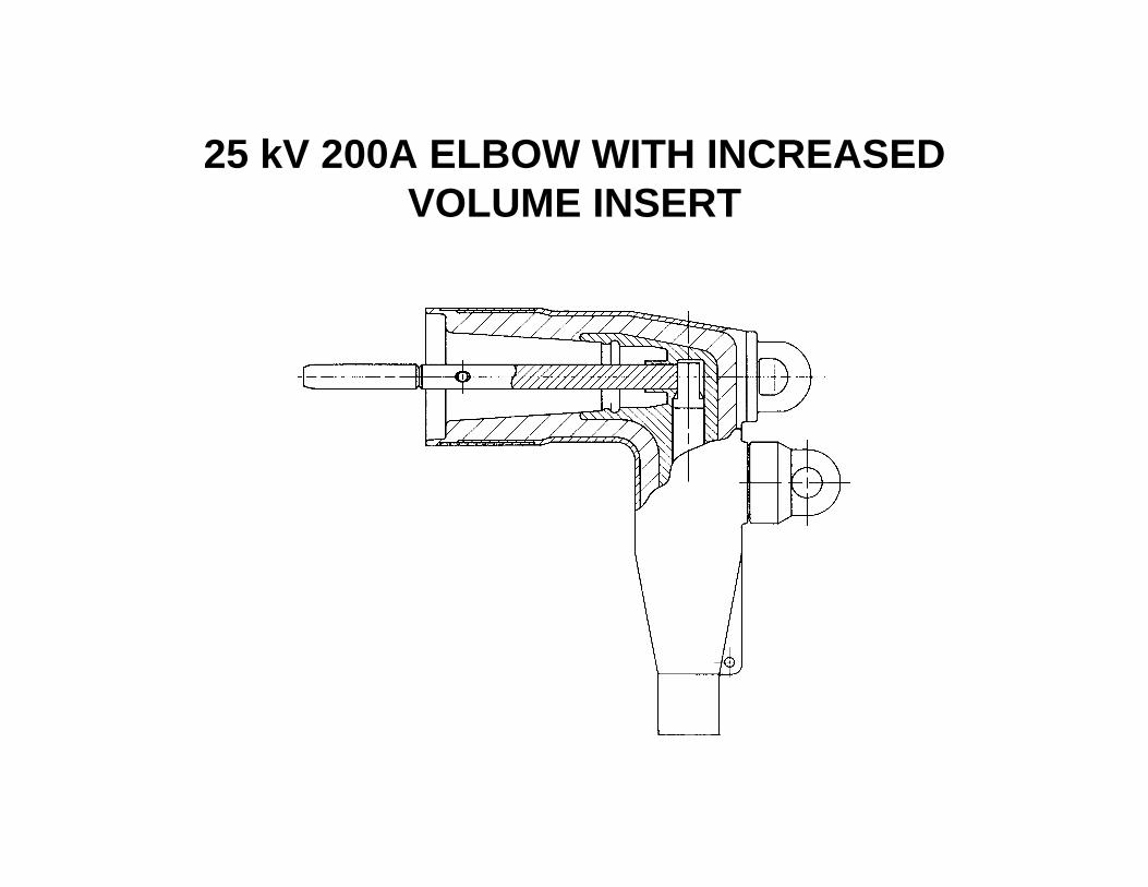
25 kV 200A ELBOW WITH INCREASEDVOLUME INSERT

25 kV 200A LOADBREAK
“ENHANCED SWITCHING”
MINIMUM INTERNAL PRESSUREDURING REMOVAL OPERATION
Existing vs. Increased Volume Cap (‘97 data)
0-1.4 1.5-2.9
3.0-4.4
4.5-5.9
6.0-7.4
7.5-8.9
9.0-10.4
10.5-11.9
12.0-13.4
13.5-15.0
0
5
10
15
20
25
30
CO
UN
T I
N R
AN
GE
0-1.4 1.5-2.9
3.0-4.4
4.5-5.9
6.0-7.4
7.5-8.9
9.0-10.4
10.5-11.9
12.0-13.4
13.5-15.0
RESIDUAL PRESSURE ps ia
Exis ting
Increas ed Volume
Vacuum Atmosphere
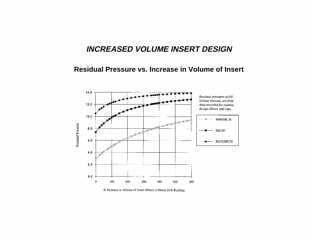
INCREASED VOLUME INSERT DESIGN
Residual Pressure vs. Increase in Volume of Insert
25 kV 200A LOADBREAK
“ENHANCED SWITCHING”
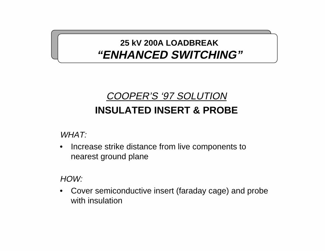
COOPER’S ‘97 SOLUTIONINSULATED INSERT & PROBE
WHAT:• Increase strike distance from live components to
nearest ground plane
HOW:• Cover semiconductive insert (faraday cage) and probe
with insulation

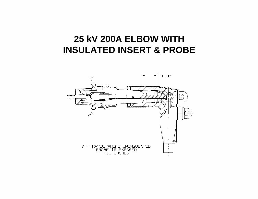
25 kV 200A ELBOW WITHINSULATED INSERT & PROBE

25 kV 200A CAP WITHINSULATED INSERT & PROBE

25 kV 200A ELBOW WITHINSULATED INSERT & PROBE
25 kV 200A LOADBREAK
“ENHANCED SWITCHING”
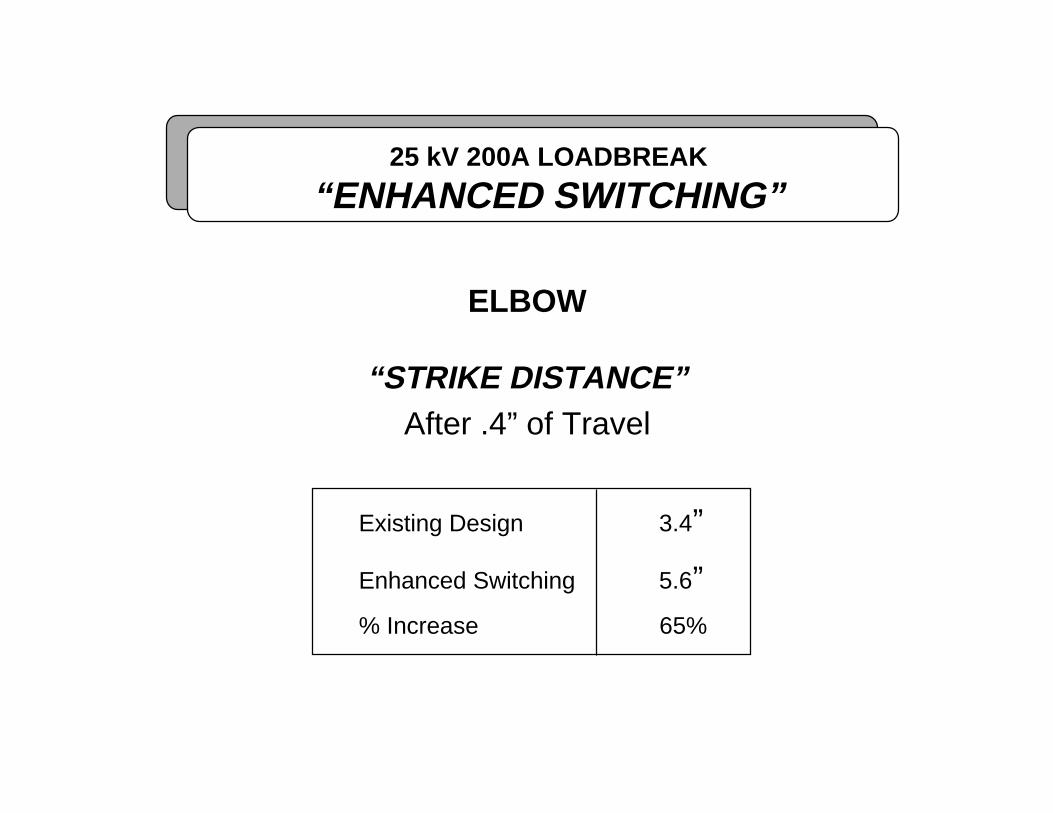
ELBOW
“STRIKE DISTANCE”After .4” of Travel
Existing Design 3.4”
Enhanced Switching 5.6”% Increase 65%
25 kV 200A ELBOW WITHINSULATED INSERT & PROBE

25 kV 200A LOADBREAK
“ENHANCED SWITCHING”
Design Qualification Tests
TEST LEVEL IEEE 386SECTION
RESULTSPASS/TOTAL
Partial Discharge 19 kV 7.4 10/10AC 1 minuteWithstand
40 kV 7.5.1 10/10
Impulse Withstand 125 kV 7.5.3 10/10

25 kV 200A LOADBREAK
“ENHANCED SWITCHING”
LAB SWITCHING TEST PROTOCOL
PROCEDURE:• Assemble elbow/cap to bushing insert without grease• Chill parts for a minimum of 16 hours at -20°C (-4°F)• Mount and switch elbow/bushing assembly within 5 minutes after withdrawal
from chiller• Circuits shall be:
– 27.5 kV line-to-ground– No load current– No adjacent ground
• Perform one seapration each on 12 samples assemblies
CRITERIA:• 12 samples shall be operated without a flashover

25 kV 200ASEPARABLE CONNECTOR
TRAVEL TRACE
Robot actuator travel profilefor elbows and caps @ -20°C

25 kV 200A LOADBREAK
“ENHANCED SWITCHING”
ELBOWSwitching Success Rate
vs. Design and Temperature(14.4 kV)
100%100%100%100%
0
50
100
<3°C >3°C <3°C >3°C
TEMPERATURE
% P
AS
S
ExistingElbow
Increased Volume Insert
25 kV 200A LOADBREAK
“ENHANCED SWITCHING”
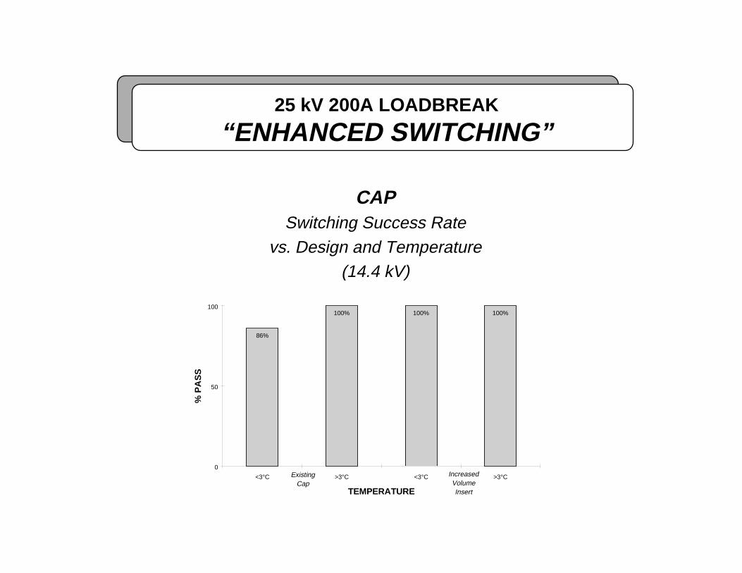
CAPSwitching Success Rate
vs. Design and Temperature(14.4 kV)
100%100%100%
86%
0
50
100
<3°C >3°C <3°C >3°C
TEMPERATURE
% P
AS
S
Existing Cap
Increased VolumeInsert

25 kV 200A LOADBREAK
“ENHANCED SWITCHING”
ELBOWSwitching Success Rate
vs. Design( 27.5 kV @ -20°C)
58%
48%
100%
0
50
100
Existing Elbow
IncreasedVolume Insert
InsulatedInsert &Probe
% P
AS
S
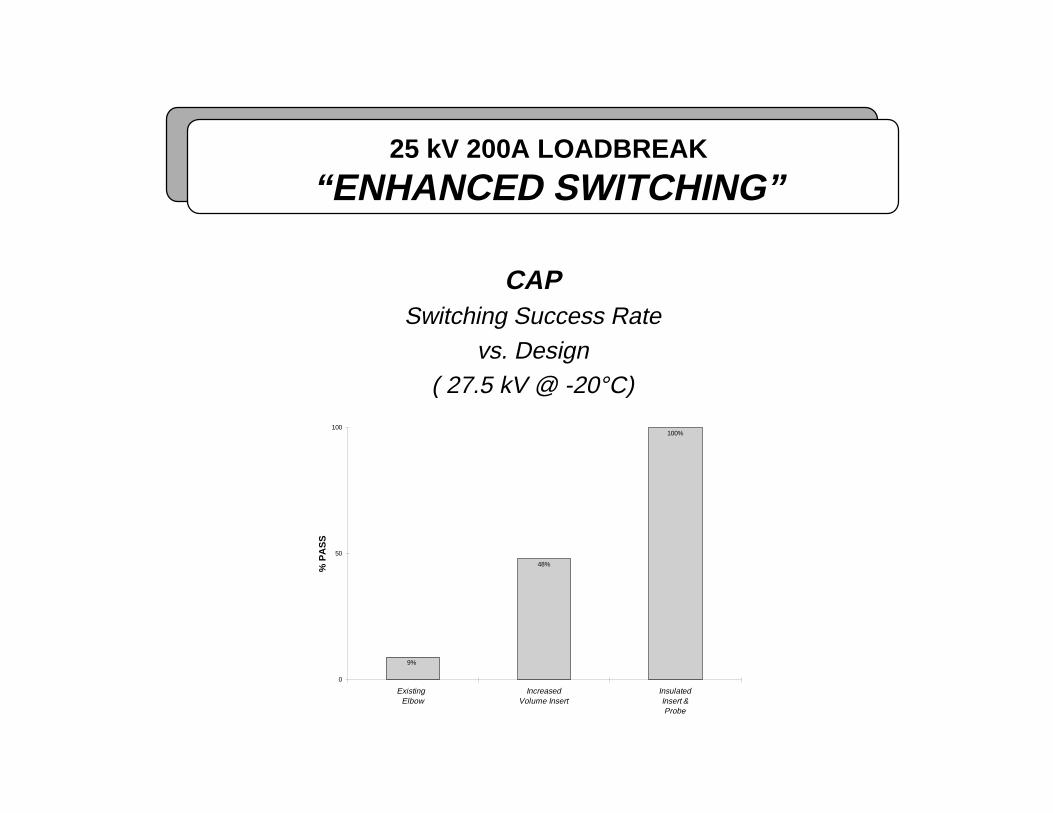
25 kV 200A LOADBREAK
“ENHANCED SWITCHING”
CAPSwitching Success Rate
vs. Design( 27.5 kV @ -20°C)
100%
48%
9%
0
50
100
Existing Elbow
IncreasedVolume Insert
InsulatedInsert &Probe
% P
AS
S
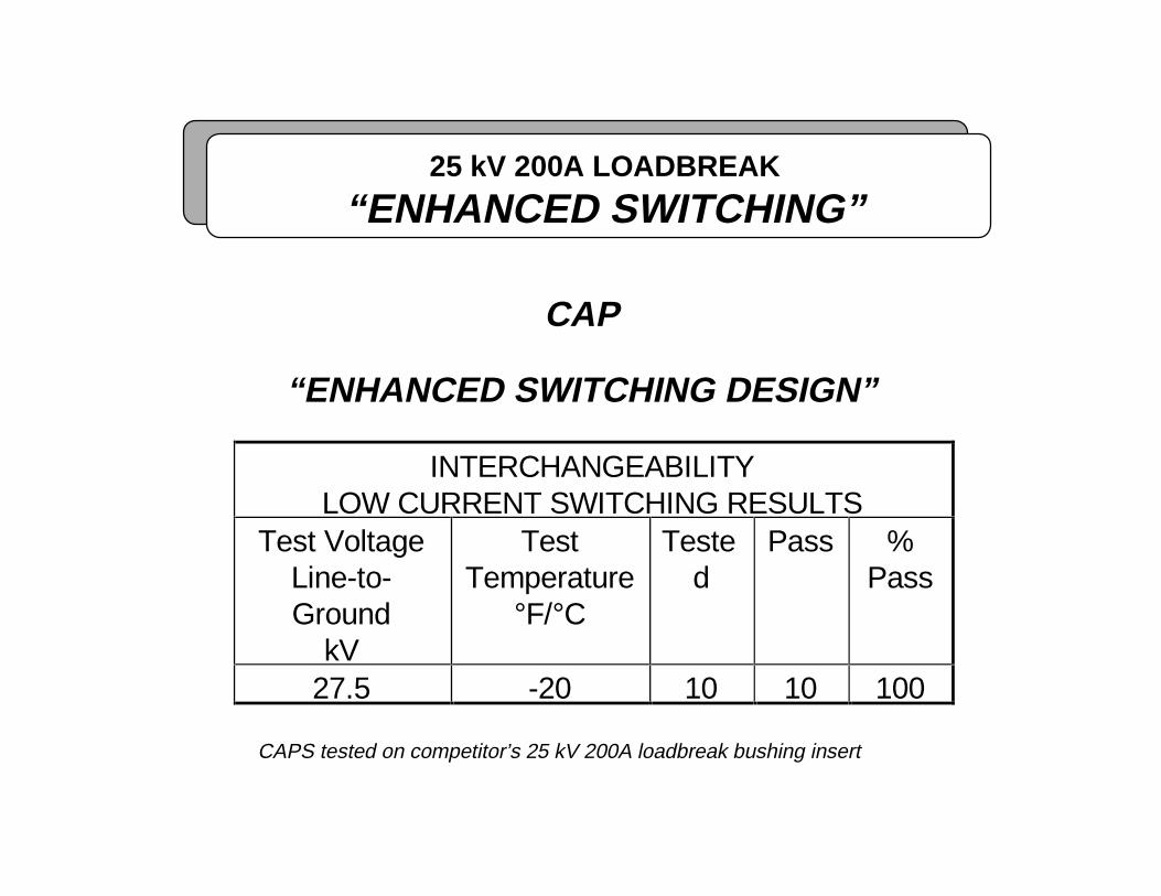
25 kV 200A LOADBREAK
“ENHANCED SWITCHING”
CAP
“ENHANCED SWITCHING DESIGN”
INTERCHANGEABILITYLOW CURRENT SWITCHING RESULTS
Test VoltageLine-to-Ground
kV
TestTemperature
°F/°C
Tested
Pass %Pass
27.5 -20 10 10 100
CAPS tested on competitor’s 25 kV 200A loadbreak bushing insert

25 kV 200A LOADBREAK
“ENHANCED SWITCHING”
INSULATED INSERT & PROBE DESIGN
“VALIDATION”
FIELD TRIALS
Voltage: 14.4 kV L-G
Temperature: <40°F
Intervals: Between 1 and 4 weeks
Operations: >200

25 kV 200A LOADBREAK
“ENHANCED SWITCHING”
FEATURES AND BENEFITSOF THE
“ENHANCED SWITCHING”ELBOW AND CAP
• Interchangeable with all new and installed bushings
• Field retrofittable without dropping load
• Retains the stress control provided by the faraday cage
• Requires no change in standard operating practices
• No flashovers due to partial vacuum effect

The following tables contain the raw data thatthe previous bar graphs were based on.

25 kV 200A LOADBREAK
“ENHANCED SWITCHING”
ELBOW
“STANDARD EXISTING DESIGN”
LOW CURRENT SWITCHING RESULTSTest Voltage
Line-to-GroundkV
TestTemperature
°F/°C
Tested Pass %Pass
14.4 <3 49 49 10014.4 >3 52 52 10027.5 -20 24 14 5827.5 +20 12 12 100

25 kV 200A LOADBREAK
“ENHANCED SWITCHING”
CAP
“STANDARD EXISTING DESIGN”
LOW CURRENT SWITCHING RESULTSTest Voltage
Line-to-GroundkV
TestTemperature
°F/°C
Tested Pass %Pass
14.4 <3 44 38 8614.4 >3 55 55 10027.5 -20 11 1 9

25 kV 200A LOADBREAK
“ENHANCED SWITCHING”
ELBOW
“INCREASED VOLUME DESIGN”
LOW CURRENT SWITCHING RESULTSTest Voltage
Line-to-GroundkV
TestTemperature
°F/°C
Tested Pass %Pass
14.4 <3 95 95 10014.4 >3 57 57 10027.5 -20 21 10 48
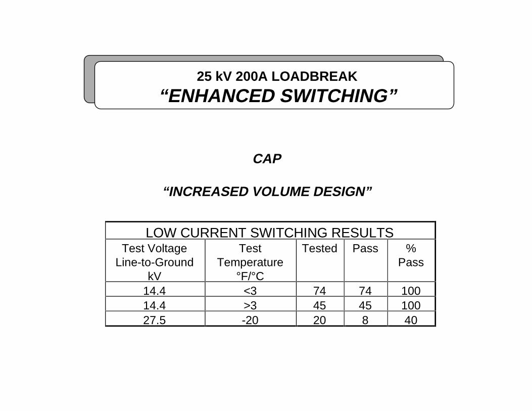
25 kV 200A LOADBREAK
“ENHANCED SWITCHING”
CAP
“INCREASED VOLUME DESIGN”
LOW CURRENT SWITCHING RESULTSTest Voltage
Line-to-GroundkV
TestTemperature
°F/°C
Tested Pass %Pass
14.4 <3 74 74 10014.4 >3 45 45 10027.5 -20 20 8 40

25 kV 200A LOADBREAK
“ENHANCED SWITCHING”
ELBOW
“ENHANCED SWITCHING DESIGN”
LOW CURRENT SWITCHING RESULTSTest Voltage
Line-to-GroundkV
TestTemperature
°F/°C
Tested Pass %Pass
27.5 -20 20 20 10027.5 +20 12 12 100
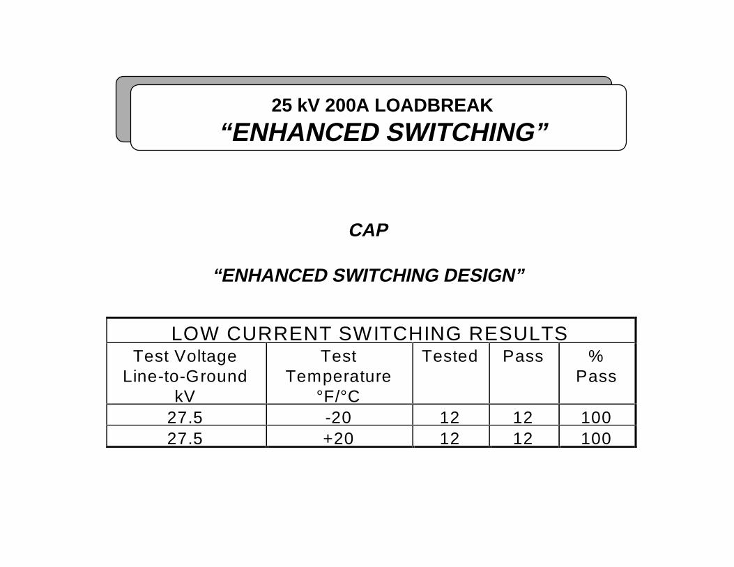
25 kV 200A LOADBREAK
“ENHANCED SWITCHING”
CAP
“ENHANCED SWITCHING DESIGN”
LOW CURRENT SWITCHING RESULTSTest Voltage
Line-to-GroundkV
TestTemperature
°F/°C
Tested Pass %Pass
27.5 -20 12 12 10027.5 +20 12 12 100
25 kV 200A LOADBREAK
“ENHANCED SWITCHING”
PROBLEM:
• The IEEE 386 200A load switching test does notdetect the partial vacuum failure mode.
WHY:
• Freshly lubricated interfaces
• Trapped pressure inside elbow on Make operation
• Break operation performed within minutes afterMake

25 kV 200A LOADBREAK ELBOWand
INSULATED PROTECTIVE CAP
TRAPPED AIR PRESSURE (psig)
MAKE OPERATION
PRESSURE DECAY RATE
%Initial Pressure = 100% e (.0075t)
t=time after installation
MEAN MIN MAXElbow 10.7 9.4 13.8Cap 10.5 9.6 13.4

25 kV 200A LOADBREAK
“ENHANCED SWITCHING”
INSULATED INSERT & PROBE DESIGN
“QUALIFICATION”
• IEEE 386-1995 TESTS SECTION
DIELECTRICSCorona 7.4AC Withstand 7.5.1DC Withstand 7.5.2Impulse Withstand 7.5.3
THERMALShort-time Current 7.6Current Cycling-Accelerated 7.10.1Current Cycling-Off Axis 7.10.2
MECHANICALOperating Force 7.14Pulling Eye 7.15
OPERATINGSwitching 7.7Fault Close 7.8