low cost attitude control system control system reaction wheel · attitude control system reaction...
TRANSCRIPT

NASA-CR'191332 Report 94044March 8, 1991
t
LOW COST ATTITUDE CONTROL SYSTEM
REACTION WHEEL DEVELOPMENT
FINAL REPORT
(NASA-CR-191332) LOW COST ATTITUDE
CONTROL SYSTEM REACTION WHEELOEVELOPMENT Final Report (Ithaco)
i00 p
G3118
N94-13140
Uncl as
0186508
Prepared for
National Aeronautics and Space Administration
Goddard Space Flight CenterGreenbelt, MD 20771
Prepared by:
ITHACO, Inc.735 W. Clinton St.
P.O. Box 6437
Ithaca, NY 14851-6437
https://ntrs.nasa.gov/search.jsp?R=19940008667 2018-08-23T23:11:37+00:00Z

Report 94044March 8, 1991
Page ii
TECHNICAL REPORT STANDARD TITLE PAGE
1. Report No. 2. Government Accession. No.
4. Title and Subtitle
Low Cost Attitude Control SystemReaction Wheel DevelopmentFinal Report
7. Author(s)
William Bialke
9. Performing Organization Name and Address
ITHACO, Inc.735 W. Clinton St.P.O Box 6437
Ithaca, NY 14851-643712. Sponsoring Agency Name and Address
Mr. Seymour KantNASA/Goddard Space Flight CenterGreenbelt, MD 20771
3. Recipient's Catalog No.
5. Report Date
6. Performing Organization Code
8. Performing Organization Report No.
#94044
10. Work Unit No.
11. Contract or Grant No.
NAS5-30307
13. Type of Report and Period Covered
Final Report
14. Sponsoring Agency Code
15. Supplementary Notes
16. Abstract
In order to satisfy a growing demand for low cost attitude control systems for small spacecraft, development ofa low power and low cost Reaction Wheel Assembly was initiated. This report addresses the details of theversatile design resulting from this effort. Tradeoff analyses for each of the major components are included, aswell as test data from an engineering prototype of the hardware.
17. Key Words (Selected by Author(s))
Attitude Control SystemReaction WheelMomentum WheelEarth Sensor
19. Security Classif. (of this report)
18. Distribution Statement
20. Security Classif. (of this page) [ 21. No. of Pages 22. Price


Report 94044March 8, 1991
Page I
TABLE OF CONTENTS
1.0
2.0
3.0
4.0
5.0
PREFACE .......................................................................................... 1
1.11.21.3
Objective ................................................................................... 1Scope of Work ............................................................................ 1Conclusions ............................................................................... 1
PHASE I SUMMARY ............................................................................ 2
PHASE II GOALS ................................................................................ 4
HARDWARE DESIGN APPROACH .......................................................... 6
4.1 Design Specifications .................................................................... 7
HARDWARE DESIGN TRADEOFFS ......................................................... 8
5.1
5.2
5.3
5.4
5.5
Structure ................................................................................... 8
5.1.1 Housing ........................................................................ 85.1.1.1 Housing Form ................................................... 85.1.1.2 Housing Material ................................................ 125.1.1.3 Structural Dynamics ............................................. 125.1.1.4 Sealing ............................................................ 17
5.1.2 Rotor Construction ............................................................ 17
5.1.3 Bearing Mounts ............................................................... 19Bearings ................................................................................... 205.2.1 Ball Bearing Tradeoffs ....................................................... 20
5.2.1.1 Bearing Type ..................................................... 205.2.1.2 Bearing Preload .................................................. 22
5.2.1.3 Bearing Material ................................................. 225.2.1.4 Bearing Load Ratings ........................................... 235.2.1.5 Bearing Tolerances .............................................. 235.2.1.6 Bearing Selection ................................................ 24
Lubrication ................................................................................ 25
5.3.1 Lubricant Wear Testing ....................................................... 275.3.2 Lubricant Performance ....................................................... 275.3.3 Lubricant Life .................................................................. 31
5.3.4 Lubricant Optical Transmission ............................................. 365.3.5 Lubricant Selection ............................................................ 36Motor ...................................................................................... 38
5.4.1 Motor Type .................................................................... 385.4.2 Motor Selection ................................................................ 39Tachometer ................................................................................ 415.5.1 Tachometer Selection ......................................................... 41
Report94044March8, 1991PageII
TABLE OF CONTENTS (CONT'D)
6.0
7.0
8.0
9.0
10.0
11.0
5.6 Motor Driver .............................................................................. 42
5.6.1 Motor Driver Design Goals .................................................. 425.6.2 Motor Characteristics ......................................................... 42
5.6.3 Driver Topology ............................................................... 435.6.3.1 Power Bridge .................................................... 435.6.3.2 Commutation ..................................................... 435.6.3.3 Pulse Width Modulation ........................................ 43
5.6.3.4 Supplementary Features ........................................ 455.6.4 Motor Driver Packaging ...................................................... 46
FINAL DESIGN DESCRIPTION ..... ......................................................... 47
6.16.26.3
Ball Bearing Suspension System ....................................................... 47Lubrication System ....................................................................... 47Motor ...................................................................................... 50
BREADBOARD UNIT MANUFACTURE .................................................... 51
7.17.27.3
Rotor Assembly Manufacture ........................................................... 51Stator Manufacture ....................................................................... 51
Breadboard Unit Configuration ......................................................... 52
BREADBOARD UNIT TEST DATA ........................................................... 53
8.18.28.38.48.58.6
Modal Survey ............................................................................. 53Drag Torque Data ......................................................................... 53Bearing EHD Film Testing .............................................................. 58External Magnetic Field Measurements ................................................ 58Power Consumption Measurements ................................................... 64
Acceptance Test Plan ..................................................................... 648.6.1 Functional Test ................................................................ 648.6.2 Performance Test .............................................................. 648.6.3 Bum-In ......................................................................... 668.6.4 Random Vibration ............................................................. 66
PHASE III STATUS ............................................................................. 67
CONCLUSION ................................................................................... 67
REFERENCES .................................................................................. 67
APPENDIX A - ITHACO REPORT 93945, REV. A

Report94044March8, 1991Page1
1.0 PREFACE
1.1 Objective
This report documents and summarizes the development work performed under Small BusinessInnovation Research Contract NAS5-30307.
1.2 Scope of Work
In order to make a low cost attitude control system viable for small, inexpensive satellites,development of a low cost, low power consumption reaction wheel was completed. Thedevelopment effort performed included all of the detail design and engineering testing of a reactionwheel and motor driver capable of being integrated into a combination reaction wheel and earthscanner, or SCANWHEEL®.
1.3 Conclusions
The development effort did not encounter any insurmountable obstacles which would preclude thelow-cost manufacture of a low-power consumption Reaction Wheel Assembly. Simplistic and
reliable techniques were employed to result in a rugged, yet efficient, design. Processes are inplace to manufacture the reaction wheel in large or small quantities, and with options for variouslevels of traceability and documentation.

Report94044March8, 1991Page2
2.0 PHASE I SUMMARY
The objective of the Phase I effort was to develop a source for a low cost spaceflight worthyreaction wheel, in order to make an attitude control system feasible for small, low cost satellites.Three vendors were solicited for cost proposals, and a make/buy decision was made to design and
produce the low cost RWA at ITHACO.
The three vendors which were contacted in the Phase I effort were Honeywell, Bendix, and
Schaeffer Magnetics. Honeywell and Bendix have been in the business of supplying space flightreaction wheels for many years. Schaeffer Magnetics was in the process of initiating a reactionwheel design and was a viable alternative. Both Honeywell and Bendix quoted non-recurringcosts for the reaction wheel on the order of $600K - $800K, and recurring costs on the order of
$60-100 K per reaction wheel. Even with relaxed specifications and deletion of requirements fortraceability and process documentation, the major reaction wheel suppliers were unable to reducethe costs of a reaction wheel to the level required for low cost missions, thus they were eliminatedfrom procurement competition due to price. The remaining potential source at Schaeffer Magneticswas found to be comparable to ITHACO in regard to design and manufacturing capability but didnot submit a bid. In order to maintain more flexibility in the control during the design andmanufacture, and to minimize overall costs, it was decided to design and manufacture the low costreaction wheel at ITHACO.
Additional results of the Phase I effort included a baseline design of the ITHACO reaction wheel.This baseline design is shown in Figure 2-1. The key features to this design were spun aluminumparts, no hermetic seal, and a compliant bearing mount. The bearings are mounted in a compliantViton housing, which minimizes the required alignment of the bearings during assembly, in anattempt to reduce manufacturing costs. The compliant support also reduces bearing loads duringrandom vibration and shock loading. The evolution of the design in the Phase II effort resulted ina substantially different design than this baseline.
The final report of the Phase I effort is contained in ITHACO Report 93558.

Report94044March8, 1991Page3
Figure2-1: Theevolutionof thedesignin thePhaseII effort resultedin a substantiallydifferentdesignthanthisPhaseI baseline.

Report94044March8, 1991Page4
3.0 PHASE II GOALS
In order to satisfy a growing need for low cost attitude control systems for small spacecraft withminimal power resources, the Phase II objectives were to develop and manufacture a low costreaction wheel with minimum power consumption. A major obstacle in the production of a lowcost attitude control system was the availability of a low cost reaction wheel. Magnetic torquersand control electronics can be built inexpensively, but no source had yet existed for low costreaction wheels. In addition, typical reaction wheels on the market consume too much power forthe stringent power budgets of small spacecraft. A second obstacle in the production of a low costattitude control system was the expense and power consumption of a horizon sensor.Development of a combined reaction wheel and horizon scanner provides solutions to the cost andpower consumption concerns of conventional hardware for a low cost attitude control system. Acombined reaction wheel and horizon scanner, or SCANWHEEL, requires only one set of
bearings and one motor, which reduces the power consumption, weight, and cost over twoseparate pieces of hardware, while improving the system reliability.
One potential spacecraft application for a low cost/low power consumption attitude control systemis the NASA Standard GAS CAN Satellite. This 150 pound satellite currently known as XSAT(Exceptional Satellite) was designed to be ejected from a Get Away Special (GAS) Cannister on theSpace Shuttle. An attitude control system is intended to be added to XSAT on a mission peculiarbasis in order to accommodate the requirements of each specific payload. In order to takeadvantage of this potential low cost satellite bus, a primary goal for the Phase II SBIR was toensure that the SCANWHEEL design was compatible with XSAT.
The funding for this SBIR was only sufficient to support the development of thereaction/momentum wheel portion of the SCANWHEEL. A separate SBIR contract (NAS-30088)for an earth scanner was directed to develop the earth scanner portion of the SCANWHEEL. A
goal in this SBIR, then, was to design the reaction/momentum wheel to be compatible with theaddition of an horizon sensor module to form a SCANWHEEL. The development performed per
contract NAS-30088 is documented in Final Report 94047.
A photograph of the hardware developed in the Phase II effort is shown in Figure 3-1.

Report94044March8, 1991Page5
Figure3-1: TheReactionWheelOutlineProvidesDualMountingSurfacesTo ExpandMountingOptionson theSpacecraft
Report94044March8, 1991Page6
4.0 HARDWARE DESIGN APPROACH
A set of ground rules was established early in the design phase of the wheel, in order to ensure thatthe design tradeoff decisions made during the hardware development were compatible with theultimate program goals. The basic approach to achieve low cost was to maintain simplicity bytaking advantage of standard components and common materials. At the same time, a rind groundrule was established to maintain the ability to upgrade any feature in the design to Class S
spacecraft hardware. Modularity in the design was also stressed as a ground rule, to takeadvantage of quantity buys of components and batch processing of subassemblies, and to minimizemanufacturing costs. In order to accommodate a variety of users with the same hardware,versatility in the design was a prominent goal. This was to be accomplished by allowing for theaddition of various options to the hardware without impact to the basic components. Being able tosatisfy the specific requirements of a variety of users is directly in line with the pursuit of low costhardware.
A ranking of the critical tradeoff parameters was established to be used in the tradeoff analysesduring the design process. These basic parameters are power consumption, cost, reliability, and
weight.
The highest ranked tradeoff parameter was deemed to be power consumption. Small spacecrafttypically have a minimum amount of surface area for solar cells, thus power is at a premium. Asan example, the XSAT satellite has a total power generation capability of 7.8 Watts. The powerconsumption of the bus is 2.5 Watts average, so the power consumption of the attitude controlsystem must be restricted to less than 3 watts total to leave just over 2 Watts for the experiment.The low power consumption was therefore imperative to enable the wheel to be practical, giventhis type of power budget.
The second ranked tradeoff parameter was cost. It was reasoned low cost production of hardwarewas essential to allow an attitude control system to be within the reach of the budgets of smallsatellites. If the costs were too high, the small satellite experimenters would inevitably sacrifice theattitude control system. In addition, the market already has sources for expensive reaction wheels,with little room for unproven competition. The only way to break into this market was with
unique, low cost hardware.
The third ranked tradeoff parameter was reliability. The long term reliability and lifetime are less
important in the low cost/high value spacecraft for which the hardware was targeted. Whilemaintaining the ground rule of upgradeability, the approach was to design the hardware for a oneyear mission as a minimum, with a goal of three years. Typical spaceflight hardware is designedwith 5 to 10 year missions in mind. The design approach to fulfill the one year mission was tokeep each component as simple as possible, while leaving room for the 'bells and whistles' in casethe hardware is commissioned to be used on a longer term mission.

Report94044March8, 1991Page7
4.0 HARDWARE DESIGN APPROACH (CONT'D)
The lowest ranked tradeoff parameter was weight. In small satellites such as XSAT, weight is notas critical as power, cost, and reliability. In some cases, hardware designs are taken to greatextremes in order to minimize weight. The heroic efforts taken during this process cansignificantly increase the costs by increasing the complexity and decreasing the dimensionaltolerances of the mechanical parts, and can lower the reliability by reducing clearances and safetymargins. However, good engineering practices of mechanical design were to be used to result inthe lowest practical weight. There is typically a see-saw tradeoff between weight and power inelectromagnetic devices, so the high emphasis on low power automatically results in a de-emphasison weight. In order to minimize material costs, the use of exotic material was discouraged.Beryllium, magnesium, titanium and composites are frequently used in spaceflight hardware tominimize structural weight, but in keeping with low cost and simplicity, these materials were not tobe used in the design.
4.1 Design Specifications
The design specifications for the reaction wheel were established in the Phase I SBIR, anddocumented in ITHACO Report 93387. A summary of the relevant specifications is presented inTable 4-1. The size was established as that expected for a small satellite on the order of XSAT.The 6 volt bus was chosen for the same reason, as that is the bus voltage of the XSAT bus. Thetypical bus voltage for spacecraft is 28 volts, but smaller spacecraft have fewer solar cells to stringtogether in series, so the bus voltage is usually lower. A goal of the design was to make it useablewith either a 28 volt bus or a 6 volt bus.
Table 4-1
Parameter Minimum Requirement Goal
Nominal Operating SpeedOperating LifeStorage LifeTorque CapabilityTorque RippleAngular Momentum @ 1000 rpmPower Consumption @ 1000 rpmWeightTemperature RangeBus Voltage
1000 rpm1 year5 years>0.02 N-m (2.8 oz-in)none0.67 N-m-s (0.5 ft-lbf-sec)<1.0 W
<2.5 Kg (5.5 lbm)0°C to 50°C6V
+6000 rpm
3 years5 yearsincreasable
<0.002 N-m (<10%)increasable<0.5 W
-34°C to 71°C
6V, 15 Vor28 V

Report94044March8, 1991Page8
5.0 HARDWARE DESIGN TRADEOFFS
The following sections address the specific tradeoff analyses performed in the design and selectionof the major components of the reaction wheel. The resulting mechanical configuration of the
reaction wheel is depicted in Figure 5-1.
5.1 Structure
The basis for the smactural design is primarily dictated by the random vibration and thermalenvironments encountered by spacecraft hardware. Random vibration responses of a heavyflywheel suspended by ball bearings can result in significant force loads on the bearings andsupport structure, and therefore must be carefully assessed. High thermal impedances in thedesign can result in high operating temperatures for bearings which will reduce the operatinglifetime.
5.1.1 Housing
The housing must perform several functions simultaneously. In addition to sealing the bearingsfor cleanliness, the housing must provide structural support of the rotor, a conductive heatsink forlow impedance heat rejection from the motor and bearings, and provide a means for mounting the
assembly to the spacecraft.
5.1.1.1 Housing Form
Four basic configurations for a flywheel suspension are shown in Figure 5-2. The most basic
configuration is a simple housing which features a combined support structure and enclosure. Thiscan accommodate either a clamshell housing arrangement as shown in Figure 5.2-a, or a pill-boxapproach shown in Figure 5.2-b. The clamshell approach provides a high rocking stiffness due tothe large bearing separation, and reduces stresses in the case of an evacuated design due to the highstrength of the conical sections. The pill-box configuration results in a lower rocking stiffness, butis easier to mount to the spacecraft. Either of the cantilever shaft options shown in Figure 5.2-cand Figure 5.2-d require bearings with a large diameter in order to achieve the required shaftstrength and stiffness, resulting in higher drag torque and thus higher power consumption than
alternate designs.
In order to make the hardware truly modular, an approach was conceived which allowed two unitsto be coupled in tandem, or stacked, in order to increase the momentum storage capacity. It wasreasoned that if a significant number of units were being manufactured, it would be more costeffective to build two standard units, rather than one larger custom unit. This could also be used to
provide redundancy. The pill-box housing fulfilled this objective. Mounting surfaces on bothsides of the housing also provides a platform on which to attach an optics package for theSCANWHEEL option. By establishing the mounting surface on the outside perimeter of the unit,the span between mounting pads is maximized, which minimizes alignment errors due tomachining tolerances. This is especially important as a mou.nting surface for the SCANWHEELoptics package. Figure 5-3 shows the versatility of the pill box housing configuration. In additionto the modularity, this approach provides more mounting options on the spacecraft.

Report 94044March 8, 1991
Page 9
Figure 5-1: Simplistic and reliable techniques were employed in the mechanical development ofthe reaction wheel to result in a rugged, yet efficient design

Report 94044March 8, 1991
Page 10
(a)Clamshell Housing - Inner Race Roatation
J
(b)Pill Box Housing - Inner Race Rotation
_i
FIIII
(c)Cantilever Shaft - Outer Race Rotation
m ,.. 1 - m
III
(d)Cantilever Shaft - Inner Race Rotation
Figure 5-2: Candidate Structural Configuration For An Enclosed Flywheel

Report94044March8, 1991Page11
I I ! I I I II ! .I
,,, , ,, , ,!,
REACTION WHEEL SCANWHEEL
I I I I ii i I_
I I i I I
SCANWHEEL / MOMENTUM WHEEL
I I I I I II !
Ill I ' I Ii
I
, t,,,t
TANDEM WHEEL
,,,, ,,,i!
DUAL SCANWHEEL
Figure 5-3: The cylindrical pill box reaction wheel configuration results in a variety ofintegration possibilities

Report94044March8, 1991Page12
5.1.1.2 Housing Material
The baseline design utilized spun aluminum components to construct the housing and support themotor. This approach was discarded due to the low strength of the spun aluminum thicknesses,and due to the potential dimensional instability of the formed material. The optical system and theball bearing suspension requires stable alignment of surfaces which may be compromised withspun parts. Spun parts or hydroformed parts require critical heat treating procedures to regain thedimensional stability of the material, which complicates the fabrication and increases the chancesfor error.
Magnesium is used in many reaction wheel housing designs due to its low density and highstructural damping, but the raw material expense and safety concerns during machining are notcompatible with the low cost objectives of the design. In addition, the poor thermal conductivityand high susceptibility of magnesium to galvanic corrosion further discourage its use where weight
is not a primary concern.
The potential high volume of production suggested that castings be considered for fabrication ofthe housing components. The recurring cost of the parts is significantly less than for a machinedpart, but for a high reliability application, X-ray and dye penetrant inspection on every piece bringsthe cost of each part close to the procurement cost for machined parts produced in relatively largelots on numerically controlled equipment. In addition, the aluminum alloys used for casting arerelatively low strength, resulting in lower safety margins and higher weight. The non-recurringcosts also makes the casting option less flexible for design changes or modifications to the
mechanical design.
Aluminum was selected as the primary structural material due to its relative low cost, high thermalconductivity, and low stiffness. A variety of aluminum alloys are categorized as highly resistant tostress corrosion cracking in Table 1 of MSFC-SPEC-522A, which allows their use an structuralapplications on Space Shuttle payloads without a Material Usage Agreement. In order to eliminateall these potential waivers, it was decided to limit material selection to materials in Table 1 ofMSFC-SPEC-522A, and dissimilar metal combinations were required to comply with MIL-STD-889.
5.1.1.3 Structural Dynamics
The stiffness of the housing is the most critical parameter in the structural design, since the
structural dynamics of the system is a function of the stiffness characteristics and the rotor mass.K the natural frequency resulting from these parameters is too high, the resulting random vibrationresponse accelerations will cause excessive loads to be transmitted through the bearings. If theresonant frequency is too low, it may fall within the range of the rotation frequency of the rotorduring operation, which will amplify the induced vibration to the spacecraft due to rotor imbalance.The maximum expected operating frequency of the rotor in any application is 6000 rpm, whichcorresponds to a minimum resonant frequency of 100 Hz. In order to determine an upper limit tothe resonant frequency, a random vibration response analysis is required.
The dynamic model, represented in Figure 5-4, is assumed to be essentially a single degree offreedom system in the axial direction, and a two-degree of freedom system in the radial direction.This will result in three dominant vibration modes, which are referred to as the axial mode, theradial translation mode, and the radial rocking mode. In the radial translation mode, the deflections
of the k2 springs are in phase, and in the radial rocking mode they are 180 ° out of phase. Thesemodes are represented in Figure 5-5.

Report94044March8, 1991Page13
,el�I�I I
kl _ +kl =support
|
Ik3 _ = rotor
AXIAL DYNAMIC MODEL
k 5 = bearing
M1
I1
k 4 = support
RADIAL DYNAMIC MODEL
Figure 5-4: Due to high concentrated mass of the flywheel, a lumped mass dynamic model isa very realistic approximation for the reaction wheel
AXIAL MODE
.,4--
RADIAL TRANSLATION MODE
RADIAL ROCKING MODE
Figure 5-5: The three primary vibration modes of the reaction wheel play a large part inpredicting beating loads during random vibration exposure

Report94044March8, 1991Page14
5.1.1.3 Structural Dynamics (Cont'd)
The response of a single degree of freedom system to a specified random vibration environmentcan be predicted by using Mile's equation, which correlates a power spectral density input into an
equivalent 3(r probable sinusoidal response as follows:
a=34_fn PSD Q
where a = acceleration
fn = resonant frequencyPSD = power spectral density at fnQ = transmissibility
Mile's equation demonstrates the dependency of the statistical response acceleration from randomvibration input on the resonant frequency and the input power spectral density. When the twosevere spectrums shown in Figure 5-6 are combined, they demonstrate a break point atapproximately 350 Hz. Higher frequencies than 350 Hz increase the statistical responseaccelerations due the larger frequency component, and lower frequencies than 350 Hz result in
higher response accelerations due to the increasing power spectral density of spectrum 1. In orderto optimize the design to accommodate both specmams, it was decided to tune the stiffness of thestructure to attain a radial resonant frequency of 350 Hz.
In the selected pill-box housing configuration, the dominant mode with the highest frequency willbe the radial translation mode. The low membrane stiffness of the housing in the axial direction
will yield a significantly lower frequency mode for the axial mode, and the beating span canselected to do the same for the rocking mode. The relatively small diameter of the housing,however, results in a high radial stiffness due to the full compliment of material about each bearingmount. The stiffness of this type of housing suspending a three pound rotor results in primary
resonant frequencies on the order 1 KHz. A primary structural resonance in the 600 to 800 Hzrange, given a typical spaceflight random vibration input spectrum, results in 3cy responseaccelerations on the order of 240 g's. If the resonant frequency is reduced to 350 Hz, the 3_
response accelerations are approximately reduced in half. Tuning of the structural stiffness inorder to attain the desired 350 Hz requires the use of a flexure support. A spoked 'spider web'flexure was found to be the most practical support. By axially offsetting the bearing centerline
from the plane of the flexure, a moment is produced during radial loading which capitalizes on thebending compliance of the flexure spokes. Figure 5-7 shows the free body model of the flexureand the resulting stiffness model equation used to tune the radial translation resonance. Thecorresponding axial and rocking stiffness models and equations are shown in Figures 5-8 and 5-9.
A pair of spoked flexures separated by a cylindrical ring has several other advantages from apackaging standpoint. The spokes allow visual and mechanical access to the flywheel when it iscompletely assembled into the housing. This eliminates the undesirable blind assemblycharacteristic of some reaction wheel designs which combine the enclosure and support structure
into a single part. With open flexures on both sides of the housing, inspection can be performedprior to close-up for presence of contamination, sufficient motor gap clearances and correctdirection of rotation polarity. During troubleshooting, visual examination of the rotor and bearingscan be performed without disturbing the critical existing conditions in the assembly. The axialsymmetry of the housing allows the same flexure to be used on both sides of the housing, whichimproves manufacturability.

Report 94044March 8, 1991Page 15
1.00
CI
P,
0.10
0.01
SPECTRUM I
I 20 Hz = .047 G2/Hz
20-57 Hz +6 dB/OCTAVE57-246 Hz .36 G2/Hz
246-2000 Hz -6 dB/OCTAVE2000 Hz .006 G2/Hz
OVERALL 12.4 Grins
DURATION 180 SEC/AXIS
SPECTRUM 2
20-225 Hz = 0.062 G2/Hz [
225--400 Hz +6 dBK)L_AVE [
4130-1000 Hz 0.193 G2/Hz [1000-2000 Hz -6 dB/OCTAVE I
TOLERANCE .+.3dB [OVERALL 15.8 Grins ±10% I
DURATION 60 SEC +10% [
SPECTRUM 3
20-100ttz = +6dB/OCTAVE [100-1000 Hz .02 G2/Hz
1000-2000 Hz -12 dB/OCTAVE
0.001
20 57 225 246 400 1000 2000
FREQUENCY (Hz)
Figure 5-6: The reaction wheel is designed to be compatible with a variety of random vibrationenvironments

Report 94044March 8, 1991
Page 16
Figure 5-7:
M0 = Fh
kr_ m
F F 16 EIm
hO h2_1
A radial stiffness model of the supporting flexure was used to tune the radialresonance of the rotor to 350 Hz
FM
R 1 R2
k = F = 192 E_____II ka - 576 EI for 6 spokes3 3
Y 11 l 1
Figure 5-8: Axial Stiffness Model
f
J
kY m
t-
28 E1 12
h211
Figure 5-9: Angular Stiffness Model

Report94044March8, 1991Page17
5.1.1.4 Sealing
Many reactionwheeldesignsarehermeticallysealed,for avarietyof reasons.Onereasonis tomaintainthesamelevelof performancein groundtestingasin orbit. This is achievedbyeitherevacuatingtheinteriorto ahardvacuumandsealingfor life, or temporarilyevacuatingandsealingtheinteriorfor all groundtestingandventingtheinteriorprior to launchsoit will beexposedtospacevacuum.An alternatemethodbackfillstheinteriorwithonehalf atmosphereof inert gasandsealsthehousingfor life, in orderto minimizetheevacuationstresseson thehousingandmaintainanoperatingpressurecompatiblewith thevaporpressureof naturalhydrocarbonoils.Thebackfilledapproachalsoimprovestheheattransferwithin themechanismby utilizing forcedconvectionfrom therotor,atthecostof additionalpowerconsumptionduetorotor windage.
Thepotentialuseof thereactionwheelin combinationwith ascanningmirror prohibitssealingoftheunit without a large,complexandexpensiveinfraredwindow. In orderto eliminatethecostsassociatedwith bothhermeticallysealingthehousingandincorporatingthis impracticalwindow,itwasdecidedto developaventeddesign.Themajorpenaltyresultingfrom thisdecisionis thattheperformancedatatakenin airwill beskewedby thewindagetorque,requiringabelljar or thernaalvacuumtestset-upto acquireactualperformancedata.However,thewindagetorquecanbeeasilycharacterizedandremovedfrom thedataby acomputerdataacquisitionsystem.Venteddesignshavebeensuccessfullyflown in manymomentumwheelandscannerapplications,soheritageisnota significantissue.
A quasi-sealedenvironmentwasattainedby usingthin (0.020")aluminumsheetstockto fabricatecoverswhich areplacedover thespokedsupportstructure.Thesearereferredto asdustcovers,oraccesspanels.Theweightof thesecoversis verysmall,becauseof theminimumthicknessused.Thefaying surfacesof thecoversaresufficientlysmoothto preventlargecontaminantsfromenteringtheunit interior,in orderto maintainbearingcleanliness.Ventingis achievedby acheckvalveeffectof thecoveredges.Whena significantpositivepressuredifferentialexistsbetweentheinteriorof thehousingandtheoutside,thecoveredgesdeflectslightly dueto thepressureloading.Thisallowsquickventingof theinteriorduringambientdepressurization.Duringambientrepressurization,theedgesof thecoverareclampedby theapplicationof externalpressure,andfilter theairwhich slowlybackfills thehousinginterior.
5.1.2 Rotor Construction
A typical solution to optimize the inertia to weight ratio of a flywheel is to couple a high inertia rimto a central shaft with a thin web. The objective is to concentrate the mass at the largest possibleradius. A common technique is to use bi-metal construction, with a steel shaft to match the thermalexpansion coefficient of the bearing material, an aluminum or beryllium web to minimize theweight of this non-inertia contributing component, and a high density rim such as tungsten, steel,or inconel to maximize the inertia contribution. The method of assembling these components is
typically an interference fit. An interference fit on the rim, however, leaves significant residualhoop stresses in this area, and creates a situation for additional thermal stresses due to thedissimilar CTE's of the materials during exposure to temperature extremes. These hoop stresses
are superimposed on top of operating stresses in the rotor due to centripidel forces, reducing themargins of safety in the rotor design.

Report94044March8, 1991Page18
5.1.2 Rotor Construction (Cont'd)
A configuration was chosen which utilized a 15-5 PH stainless steel shaft in order to match theCTE of the bearing material as closely as practical. The rim material is desired to be non-magnetic,to minimize the potential field disturbances, and to avoid eddy current losses between the rotor andthe aluminum housing, should the rotor become slightly magnetized. A stainless steel rim was a
potential candidate, but the strength of non-magnetic stainless steel in the 300 or 400 series is verylow, resulting in low safety margins for high speed operation. Simple calculations revealed only aminor weight penalty for using a low density rim material. A benefit to using a low densitymaterial is a sharp increase in rotor strength due to the increased cross section. In order to reducecosts by minimizing the number of parts in the rotor assembly, an aluminum part combining therim and web was selected. Aluminum alloy 6061 has been found to be inexpensive to machine,highly resistant to stress corrosion cracking, very dimensionally stable, and exhibiting anextremely high fracture toughness.
The stainless steel shaft is thermal fitted into the aluminum flywheel and secured additionally with astainless steel hex nut. The motor selected in a subsequent section consists of high inertia coldrolled steel components bonded into the aluminum rim with structural epoxy. Samarium Cobaltmagnets are bonded to the cold rolled steel magnet ring with the same structural epoxy, andaluminum spacers are bonded in the area between the magnets for increased inertia and improvedstructural strength. The cold rolled steel components are plated with electroless nickel to preventcorrosion. A thermal fit was not used on the motor components to avoid the thermal stresses in therim and the potential distortions which could occur in the motor gap. The concentration of themass of the motor on the rim more than compensates for the slight weight penalty accepted in orderto use a low density material such as aluminium in the inertia rim. The web can be thinned downto reduce weight at the sacrifice of reduced stiffness. Rather than reducing the web thickness, theunneeded weight was removed by boring lightening holes in the rim. This retains much of theoriginal stiffness, and allows visual and mechanical access through the rotor. This improves theinspectibility of the assembled unit, improving the reliability by more complete screening ofworkmanship defects.
In order to minimize the imbalance of the rotor due to the tolerances on the parts and the inevitable
asymmetry of the structural epoxy used to bond the magnets and motor iron into the flywheel, abalancing process is required. The equipment and expertise required to perform precisionbalancing are extensive, so it was decided to subcontract the balancing. Schenck-Trebel has an
operation nearby on Long Island, which does large and small volume, coarse and precisionbalancing of rotors. Schenck's equipment is known worldwide as the best balancing equipmentavailable. Subcontracting was set up with Schenck to ship our completed rotor to them with
tooling bearings mounted on the shaft, and they fabricated tooling to suspend the rotor on theirbalancing equipment. When left to the professionals, experience has shown that the precisionbalancing can be a very simple and reliable process. The balancing operation is performed byremoving material from the edge of the aluminum rim on a grinder. The low density aluminumalloy rim is ideal for balancing operations, for it improves the resolution obtainable in a typicalbalance cut.

Report94044March8, 1991Page19
5.1.3 Bearing Mounts
The baseline design used a compliant bearing mounting scheme, to avoid the potential bearingstresses due to misalignment of the bearings. This was to be achieved by mounting the bearings ina flexible elastomer. This concept has a lot of merit for stressless operation of a set of bearings
operating with minimal loads, however, the dimensional stability of such a configuration may notbe sufficient for the application. Elastomeric materials tend to cold flow over time, resulting indimensional changes in the direction of the momentum vector of the flywheel. Low accuracysystems may not require this stability, but the ground rule requiring upgradeability excludes thisconfiguration. In addition, the application where a scanning mirror is coupled to the shaft requireseven more dimensional stability of the rotation axis. As a result, a rigid beating mounting scheme
is required.
The considerations involved in selecting the bearing mounting scheme include alignment, thermalcompatibility, and the prevention of fretting corrosion between similar materials. A 15-5 PHstainless steel bearing mount aligned within the linebored housing with a precision slip fit wasselected due to its close CTE match with the bearing material. The sleeve within the mount inwhich the outer race of the bearing is installed is coated with Titanium Nitride to prevent the
fretting corrosion which would be inevitable at the beating and mount interface due to the relativemicroscopic movements of the race during operation. The spring preload scheme selected requiresone bearing to be fixed, and one bearing to be able to float axially during relative changes in theshaft and housing dimensions due to thermal expansion and transient pressure differentials on thehousing. The Titanium Nitride coating ensures that this floating action of the second bearing is
preserved.
The preload spring requires some method of snubbing excessive deflections, so that the spring isnever fully compressed. This was achieved by specifying flanged bearings. On the fixed end, theflange is used to mount the bearing. On the floating end, the flange limits the excursion of thespring. This configuration also allows the use of identical bearing mounts on both ends. Thisresults in fewer part types for lower cost procurement.
The inner races of the bearings are secured to the shaft with precision spanner nuts. A double nutscheme is employed for the implementation of positive locking techniques. A common method of
positively locking hardware is to stake the threads with epoxy. In applications near bearings, useof epoxy is not recommended due to the potential of epoxy migrating to critical bearing surfaces.The use of a double nut allows the first nut to be installed with no staking. The second nut locks
the first nut, and can be staked with epoxy since it is sufficiently removed from the criticalsurfaces. This configuration has another advantage when a scan mirror is coupled to the shaft in aSCANWHEEL application. By eliminating the second nut on the scanner side of the housing, amirror can be easily added by screwing it directly onto the threaded shaft, thereby becoming thesecond nut.

Report94044March8, 1991Page20
5.2 Bearings
Alternatives to ball bearing suspension systems for reaction wheels and other spaceflight systemshave been sought for many years. Magnetic beatings have been successfully built and tested inorder to increase the lifetime of rotating assemblies, but have rarely won out over conventional ballbearing suspensions in flight hardware fabrication. A weight penalty is encountered when themassive magnetic bearings are compared to compact passive ball bearing suspension systems, and
the active control system required to stabilize the magnetically susp. ended rotor typically lowers theoverall reliability to the point that passive ball bearings are a superior choice. The power requiredfor the bearing control system also consumes a large portion of the power gained from the lowdrag torque advantage of the magnetic bearing. The tow cost and minimum lifetime requirementsfor the SBIR reaction wheel excluded magnetic bearings from contention, resulting in a tradeoff
analysis between various configurations of ball bearing systems.
5.2.1 Ball Bearing Tradeoffs
Ball bearing suspension systems have been used successfully in many reaction wheel applications.The variety of configurations are as numerous as the number of reaction wheel vendors. Thetradeoffs involved in the selection of the bearing configuration are the bearing type, the preload
scheme, the bearing materials and geometry, and the mounting method.
5.2.1.1 Bearing Type
The first tradeoff issue which must be addressed is the bearing type. Because of the precision and
size of the bearings which are required for the reaction wheel, the bearings fall in the category ofseries R instrument bearings. Series R deep groove bearings have full shoulders on both sides ofthe raceways of the inner and outer rings. They can accept radial loads, thrust loads in eitherdirection, or combinations of loads. In order to allow assembly with the full shoulders, these
bearings require a two-piece steel ribbon type retainer. Series R angular contact bearings have onering shoulder partially or totally removed. They can support thrust loads in one direction orcombinations of radial and thrust loads, but not radial loading alone. Load and speed capacities are
higher than for deep groove bearings, since the removed shoulder on one race allows a higher ballcompliment. The removed shoulder also allows the use of a phenolic retainer commonly referredto as a 'halo cage'. This is desirable for low retainer wear, and the ability to vacuum impregnatethe retainer with a small supply of lubricant. Both deep groove and angular contact ball bearingscan be combined to form a duplex pair for increased capacity and rigidity. Figure 5-10 showsalternative methods of combining both types of beatings, in duplex pairs and separately. Twoaxially separated deep groove beatings have the advantage that they could potentially be usedwithout preloading, resulting in low drag torque, but this would result in high non-repetitiverunnout. Two duplex pairs have the advantage of high capaci'ty and low runnout, but will be more
costly and consume more power due to the higher bearing count and expense of matching theduplex pairs. A set of duplex pairs on one end and a deep groove bearing on the other end has theadvantage of high capacity, but requires two types of bearings which will reduce the advantage ofquantity buys. A set of two angular contact bearings has all of the advantages of low runnout dueto the required preload, low cost and low drag torque due to the low bearing count, and highcapacity from the angular contact beatings. The disadvantage of this configuration of being unableto accept bi-directional thrust loading during operation is not an issue in the reaction wheel design,since the application does not require thrust loading during operation. This configuration wastherefore selected, requiting a preload scheme.

Report94044March8, 1991Page21
TYPE
DUAL DEEPGROOVE
ADVANTAGES
LOW DRAGLOW COST
DUAL DUPLEX PAIRS HIGH CAPACITYLOW RUNOUT
DUAL ANGULAR CONTACT LOW RUNOUTLOW DRAGLOW COSTHIGH CAPACITY
DUPLEX PAIR / DEEP GROOVE HIGH CAPACITY
Figure 5-10: Bearing Configuration Tradeoff
Report94044March8, 1991Page22
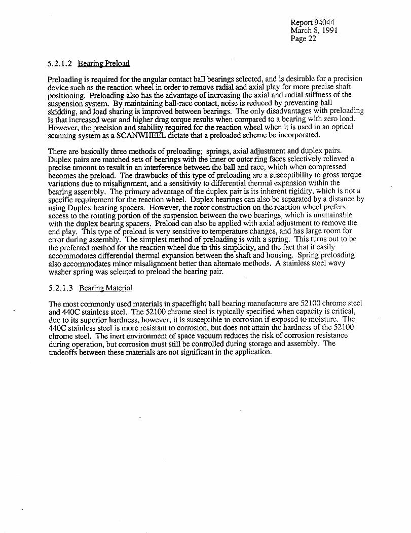
5.2.1.2
Preloading is required for the angular contact ball bearings selected, and is desirable for a precisiondevice such as the reaction wheel in order to remove radial and axial play for more precise shaft
positioning. Preloading also has the advantage of increasing the axial and radial stiffness of thesuspension system. By maintaining ball-race contact, noise is reduced by preventing ballskidding, and load sharing is improved between bearings. The only disadvantages with preloadingis that increased wear and higher drag torque results when compared to a bearing with zero load.However, the precision and stability required for the reaction wheel when it is used in an opticalscanning system as a SCANWHEEL dictate that a preloaded scheme be incorporated.
There are basically three methods of preloading; springs, axial adjustment and duplex pairs.Duplex pairs are matched sets of bearings with the inner or outer ring faces selectively relieved aprecise amount to result in an interference between the ball and race, which when compressedbecomes the preload. The drawbacks of this type of preloading are a susceptibility to gross torquevariations due to misalignment, and a sensitivity to differential thermal expansion within thebearing assembly. The primary advantage of the duplex pair is its inherent rigidity, which is not aspecific requirement for the reaction wheel. Duplex bearings can also be separated by a distance byusing Duplex bearing spacers. However, the rotor construction on the reaction wheel prefersaccess to the rotating portion of the suspension between the two bearings, which is unattainablewith the duplex bearing spacers. Preload can also be applied with axial adjustment to remove theend play. This type of preload is very sensitive to temperature changes, and has large room for
error during assembly. The simplest method of preloading is with a spring. This turns out to bethe preferred method for the reaction wheel due to this simplicity, and the fact that it easilyaccommodates differential thermal expansion between the shaft and housing. Spring preloadingalso accommodates minor misalignment better than alternate methods. A stainless steel wavywasher spring was selected to preload the bearing pair.
5.2.1.3 Bearing Material
The most commonly used materials in spaceflight ball bearing manufacture are 52100 chrome steeland 440C stainless steel. The 52100 chrome steel is typically specified when capacity is critical,
due to its superior hardness, however, it is susceptible to corrosion if exposed to moisture. The440C stainless steel is more resistant to corrosion, but does not attain the hardness of the 52100
chrome steel. The inert environment of space vacuum reduces the risk of corrosion resistanceduring operation, but corrosion must still be controlled during storage and assembly. Thetradeoffs between these materials are not significant in the application.

Report94044March8, 1991Page23
5.2.1.3 Bearing Material (Cont'd)
Several new materials have been recently introduced in the ball bearing market. Ceramic bearingsand hybrid beatings with ceramic balls have been developed which greatly reduce wear, and havethe potential of being used without lubricants. The brittle nature of the ceramics, however, is notcompatible with the random vibration and pyrotechnic shock associated with spaceflig.htenvironments. Another state of the art technology in ball bearing design is incorporating TitaniumCarbide (TIC) coated balls. During operation in the sub-EHD speed region, a lubricant is
ineffective in providing satisfactory film to prevent contact between the balls and races. When thishappens the asperities of the mating components can come together under sufficient pressure tomicro-weld. As the ball advances, the weld area breaks, resulting in metal particles in thelubricant. As wear progresses, the lubricant becomes a slurry of degraded lubricant and metal wearparticles, which further accelerates the deterioration of the mating components. Using dissimilarmaterials for the balls and races significantly reduces the wear in this regime. The insolubility ofthe TiC ball coating with the steel races eliminates the microwelding during sub-EHD operation. Inaddition, the TiC coating provides an 'emergency lubrication' scheme, providing extended lifetimethroughout the entire operating speed range even after the lubricant supply is completely exhausted.
5.2.1.4 Bearing Load Ratings
The required capacity of the selected bearings is dictated by the loading during launch randomvibration. In order to avoid permanent deformation of the bearing races (known as brinelling), themaximum contact stress levels in the bearing must be below 580,000 psi. This stress level is thebasis for static load ratings established by the bearing manufacturers. The expected load levels aredetermined by random vibration analysis of the structure. These loads vary significantlydepending on the launch vehicle's random vibration spectrum and the dynamics of the reactionwheel structure.
5.2.1.5 Bearing Tolerances
The standard tolerances on bearings are specified by the Anti-Friction Bearing Manufacturers'Association (AFBMA). Tolerance classes are specified in various degrees of precision fromABEC 3 to ABEC 9. The ABEC 7 class or better was selected for the reaction wheel, based on
recommendations in DOD-A-83577A, the military specification for moving mechanical assemblies
for space vehicles.

Report94044March8, 1991Page24
5.2.1.6 Bearing Selection
The final bearing selection was based on availability. In order to minimize costs and lead time, itwas decided to purchase bearings available off-the-shelf from leading bearing manufacturers. Ahigh capacity R4 bearing was selected from The Barden Corporation. This bearing is a hybrid of aconventional R4 bearing which has a high load rating. Thin section bearing tolerances, larger ballsand a low conformity ratio were designed into the bearing to lower the contact stresses and increase
the capacity. The negative tradeoff of this configuration is higher drag torque. However, thesesame parameters increase the lubricant film thickness, resulting is less asperity contact and lesswear. The Barden Corporation does not have TiC coated balls available off-the-shelf, but astandard R4 bearing is available from Miniature Precision Bearing Corporation (MPB) with TiCcoated balls. A comparison of the parameters of the MPB bearing and the Barden bearing isshown in Table 5-1. The capacity of the Barden bearing allows it to be used with nearly anycurrent launch vehicle random vibration specmma. The capacity of the TiC coated MPB bearing iscompatible with many of the new small launch vehicles, including the Pegasus and the Air ForceSmall Launch Vehicle. Since there are many potential applications of small satellites which mayuse the smaller launch vehicles, it was decided to maintain flexibility in the design to allow either
bearing to be used. This was simplified by the fact that the outline of both bearings is identical.
Table 5-1
Bearing Selection Comparison
Manufacturer MPB Barden
Part Number
Material
Ball Size
Ball Compliment
Contact Angle
Axial Capacity
Radial Capacity
Dynamic Load Rating
Maximum PSD @ 365 Hz*
Maximum PSD @ 90 Hz**
Maximum Random rms acceleration
Maximum Steady State acceleration
* 3 sigma loads, Q=10** 3 sigma loads, Q=6
CR4FM7LD S FR4HX 1
52100 Steel w/TiC 440C Stainless Steelcoated balls
3/32" 9/64"
9 8
10.0 ° 12.7 °
140 lbf 407 lbf
67 lbf 206 lbf
172 lbf 520 lbf
0.028 g2/Hz 0.26 g2/Hz
0.28 g2/Hz 2.4 g2/Hz
14.8 Grms 45.2 Grms
37.8 g's 116 g's

Report94044March8, 1991Page25
5.3 Lubrication
Lubrication is required in a ball bearing to provide a separation film between the ball and racesurfaces in order to minimize wear usually associated with microwelding of mating asperities on
the bearing surfaces. The most common types of lubrication systems are dry films and liquidlubricants such as oil and grease.
Dry film lubricants such as MoS2 have the advantage of vacuum stability and low viscous drag andare used in some low duty cycle applications, but do not have the endurance for a continuouslyoperating system such as a reaction wheel. There have been non-spaceflight applications where theTiC coated balls have been used without lubrication. This would be extremely attractive for the
attributes of low power consumption, no outgassing contamination, and no lifetime dependency onlubricant loss rates. This was considered to be too unproven and risky for a rugged, low cost
design.
Liquid lubrication systems using grease and/or oil have been used successfully in many reactionwheel applications. An oil lubrication system was eventually selected over grease in order to avoidthe unpredictable drag torque behavior of greases over temperature and life. Since the suspension
system is vented to space vacuum, a low vapor pressure oil is required to minimize lubricantdepletion due to evaporation. Bray 815Z oil was originally selected, since it has been usedsuccessfully on ITHACO's Conical Earth Sensors, and has become routine for space hardwaresince it meets NASA/NHB outgassing and flammability requirements. Bray 815Z is a syntheticflourocarbon perfluoropolyalkylether (PFPE) oil.
Many experiences with synthetic flourocarbons such as Bray 815Z have shown that they do notperform well under boundary lubrication conditions (Ref. 1,2). Typically, performance in theboundary region is enhanced by using antiwear additives. However, the PFPE fluids are unable todissolve additives, so significant wear can be expected when operating in the boundary region. Inaddition, the Bray 815Z has demonstrated polymerization when used in high wear applications. Ithas been demonstrated that under boundary lubrication, metal flourides are formed at the asperity
contacts, which then go on to catalytically decompose the remaining fluid.
The TiC balls used in the MPB bearings would indeed reduce the amount of wear during
boundary region operation and greatly reduce the chances of polymerization of the Bray oil (Ref2), but the knowledge of a catastrophic failure mechanism with the chosen lubricant in a requiredoperating mode demanded that alternatives be investigated.
Several candidate lubricants were involved in the initial tradeoff study to select a lubricant for the
suspension system. The natural hydrocarbons were rejected due to their high vapor pressureswhich were incompatible with the required vented design. A newly synthesized hydrocarbon fromPennzoil which has a vapor pressure as low as the Bray 815Z was considered to be unproven.This lubricant, known as Pennzane TM X2000, has since been life tested in a spaceflight mechanismat TRW (Ref. 3) and has been tested in boundary lubrication tests at Aerospace Corp (Ref. 4). Thetest results have demonstrated successful performance operating in the boundary region undervacuum conditions.

Report94044March8, 1991Page26
5.3 Lubrication (Cont'd)
The properties of the Bray 815Z and the Pennzane TM X2000 are listed in Table 5-2 for comparison.The relevant properties include the viscosity, the viscosity index, and the vapor pressure. It can beseen from the table that the viscosity of the Bray is higher at room temperature, which will
contribute to less wear by promoting a lower EHD liftoff speed. The high viscosity, index of theBray is also desirable to reduce the performance variations over temperature excursaons and tosustain EHD liftoff as temperatures are increased. The vapor pressures of the two oils are nearlyidentical, but the molecular weight of the Pennzane TM is lower, which will result in less lubricantdepletion due to evaporation. Drag torque at room temperature should be less with the Pennzane TM
than with the Bray 815Z due to the lower viscosity, but low temperature drag torque will increasedue to the low viscosity index and higher pour point of the Pennzane TM.
Viscosity
@ 100°C (ASTM D445)
@40°C (ASTM D445)
@0°C (ASTM 02602)
@-20°C (ASTM D2602)
@-40°C
Viscosity Index (ASTM D2270)
Flash Point (ASTM D92)
Fire Point (ASTM D92)
Pour Point (ASTM D97)
Molecular Weight
Density @ 20°C (ASTM D1298)
Refractive Index (ASTM D1747)
Total Weight Loss
Vacuum Condensable Material
Vapor Pressure 125°C
Vapor Pressure 20°C
Table 5-2
Lubricant Property Comparison
Bray 815Z Pennzane TM X2000
45 cSt 14.7 cSt
148 cSt 112.0 cSt
1000 cP
1125 cSt 6000 cP
11500 cSt 66500 cP
350 135
299°C 315°C
330°C 326°C
- 112°C -57°C
7000 gm/mole 910 grrdmole
1.866 gm/ml 0.846 gm/ml
1.294 1.4691
0.8% 0.160%
0.05% 0.056%
2 x 10 -7 Ton" 4 x 10 -7 Tort
8.7 x 10 -12 1 x 10 -12 Tort"

Report94044March8, 1991Page27
5.3.1 Lubricant Wear Testin_
In order to assess the suitability of Pennzane TM in the T-SCANrWHEEL, a sample was procuredand tested in the T-SCANWHEEL Engineering model (Ref. 5). The testing performed consistedof measurements of EHD liftoff speeds and drag torque with the Pennzane TM lubricant as a
function of temperature. The EHD liftoff speed was measured by monitoring, on a chart recorder,the electrical series resistance through the bearings during the acceleration of the rotor. The speedat which electrical isolation was acquired was recorded, and the testing was repeated while the
temperature of the assembly was elevated. The results are compared with similar tests performedusing the Bray 815Z. A graph of the EHD liftoff speed versus temperature for the Barden highcapacity bearings is shown in Figure 5-11, with the Bray data superimposed on the Pennzane TM
data. The data show that the Pennzane TM lubricant may result in more bearing surface wear than
the Bray 815Z at a similar temperature. This is due primarily to its lower viscosity and lowerviscosity index. From these data it can be seen that the Pennzane TM provides sufficient EHD liftoff
capability in the application of a SCANWHEEL operating at a biased speed of 2000 to 3000 rpm,as long as the ambient temperature is below 35°C. Table 5-3 shows the relative EHD liftoff speedsfor the two lubricants and the two optional bearings used in the suspension system. The fact thatthe EHD liftoff speed for the MPB bearings is greater than for the Barden high capacity beatings is
compensated for by the TiC coated balls, so both bearings are relatively equal as far as wear isconcerned.
The Pennzane TM lubricant alone will result in more wear than the Bray when used at speeds below
2000 rpm as in a bi-directional reaction wheel application. However, the additional wear is notcatastrophic like the potential polymerization of the Bray, and can be minimized with an extreme
pressure additive such as lead napthanate.
Table 5-3
Barden SFR4HX1MPB CR4FM7 w/TiC coated balls
Nominal EHD Liftoff Speed @ 23°C
Bray 815Z Pennzane TM
550 rpm 1000 rpm1200 rpm 2100 rpm
5.3.2 Lubricant Performanc.e.
The performance of a lubricant in the reaction wheel application is primarily a function of viscosity.
Higher viscosity will cause higher bearing drag torque, which will result in a loss of torquemargin, and higher steady state power consumption. The viscosity versus temperature relationshipfor the Pennzane TM and the Bray 815Z is presented in Figure 5-12. The lower viscosity index of
the Pennzane TM is apparent, and will be a source of more varied performance over temperature. Inorder to quantify the performance changes, testing was performed on the engineering modelreaction wheel at room temperature and at -30°C. Steady state power consumption at 2500 rpm
was compared, and drag torque measurements were made from 2500 rpm to 100 rpm. The dragtorque data for the high capacity 440C stainless steel Barden bearing (SFR4HX1) is shown in
Figure 5-13. All of the drag torque data were taken in air, and windage was removedmathematically to result in a measurement of bearing drag torque. The comparison is made using10 ml of free oil in identical bearings. As expected, it can be seen that the room temperature drag
torque is lower with the Pennzane TM due to its lower viscosity, but the low viscosity index resultsin significant increases in drag torque at low temperature. With the high capacity Barden bearings,the drag torque with the Pennzane TM at cold temperature will increase by .approximately one oz-inover the Bray 815Z. This will increase the steady state power consumption at 2500 rpm by
approximately 2 Watts at cold temperatures.

Report 94044March 8, 1991
Page 28
1000-
im
hum mn m u
] [][]
LJ U
[]
£3 []
g Pennzane I[] Bray 815Z |
!
100'
22 2..4 26 28 30 32 34 36 38 40 42
TEMPERATURE ("C)
Figure 5-11: EHD Liftoff Vs. Temperature (SFR4HX1 Bearings)

Report 94044March 8, 1991
Page 29
@
8
-60
m-,m
-40
),t,),_Jr,
I nnnnilnnnr
[]1000
10(1
18
-20
rl
20 40 60 80 lOO
TEMPERATURE (°C)
Figure 5-12: Lubricant Viscosity Vs. Temperature

Report 94044March 8, 1991
Page 30
2.50
ZOO
1.50
Q,,.v
1.00,.vr-,
0.50
0.00
0
JI
f
500 1000 1500 2000
ROTOR SPEED (RPM)
m BRAY 815Z23°C[] BRAY S15Z -30°C '_ PE NNZANrEX2000 23°C
.....-:
v
PENNZANEX2000"30°C [
2.5OO
Figure 5-13: Bearing Drag Torque (Barden SFR4HX1)

Report 94044March 8, 1991
Page 31
5.3.2 Lubricant Performance (Cont'd)
The Barden bearings utilize a very close race conformity in order to optimize the load carryingcapacity, which results in high drag torque friction levels. The close conformity also increases thedependency of drag torque on lubricant viscosity. The alternative standard R4 bearing from MPBwith TiC coated balls is also used interchangeability in the reaction wheel design, which exhibits
lower drag torque friction. This bearing contains smaller balls and a higher conformity ratio tominimize the drag torque losses. However, the static load capacities of this bearing are onlycompatible with launch vehicles with low random vibration levels such as the Pegasus. Thesebearings were also tested with the Pennzane TM lubricant at low temperatures. Figure 5-14 showsthat the steady state drag torque at temperatures down to 0°C is relatively unaffected. However,below 0°C, the drag torque becomes somewhat unpredictable. Figure 5-15 shows the drag torqueat -10°C, where some unpredictability in the drag torque is seen below 1800 rpm. Figure 5-16shows the drag torque behavior at -20°C. A severe reduction is observed in the drag torque at thistemperature above 1500 rpm. Below 1500 rpm the drag torque increases and becomesunpredictable. It is surmised that this effect is due to temporary channeling of the high viscosity oilat high steady state speeds, and subsequent collapsing of the channels as the ball velocity isreduced to a point where the thick lubricant can flow back into the ball track before the next balladvances. This condition may prevent the lubricant from wetting the bearing surfaces and formingan EHD film, so higher wear could result at temperatures below 0°C. Figure 5-17 shows thebearing drag at -30°C. At this severe temperature, the drag torque becomes extremelyunpredictable. The conclusions of this testing with the MPB bearings suggest that the lubricationmechanisms are not 100% effective at temperatures below 0°C, resulting in increased beating wearand unpredictable torque behavior. For this reason, long term operation with the Pennzane TM
lubricant should be avoided at this temperature extreme.
The temperature testing also included measurements of the breakaway torque required to cold startthe motor. In all cases, the cold start was achieved with less than 0.3 Volts of torque command,
which corresponds to less than 0.2 oz-in. This did not seem significantly affected by temperaturewith either of the two alternate bearings.
5.3.3 Lubricant Life
When determining the design lifetime of a pair of lightly loaded instrument bearings such as thoseused in the reaction wheel design, the classical ball bearing failure mode of fatigue is not a seriousconsideration. Rather, failure is typically initiated by lubrication system inadequacy, which in thereaction wheel design would most likely result from lubricant depletion due to evaporation andsurface migration. The oil supply within the bearing is retained between the balls and the racewayswithin the limits of surface tension. A meniscus of oil is formed at the ball/race contact which is
circulated beneath the balls to form the EHD separation film.

Report94044March8, 1991Page32
<
0.9
0.8
0.7
0.6
0.5
0.4
0.3
0.2 ./0.i
500 1000 1500 2000
ROTOR SPEED (RPM)
I.o.c ,,lOOC,_ocI
2500
Figure 5-14: Drag Torque Vs. Speed and Temperature (MPB CR4FM7 with TiC Coated Ballsand Pennzane TM Lubricant)

Report94044March8, 1991Page33
C_
e_
0.8
0.7
0.5
0.4
0.3
0.2
0.1
0 5OO 1000 1500
ROTORSPEFA)(RPM)
1,23°C []-lO°C _-10°C _-looc I
2000 2.5OO
Figure 5-15: Drag Torque Vs. Rotor Speed at -10°C (MPB CR4FM7 with TiC Coated Ballsand Pennzane TM Lubricant)

Report94044March8, 1991Page34
0.8
0.7
0.6
o.5
C>'
L_ 0.4<
0.3
0.2
0.I
0 500 1000 1500 2000
ROTOR SPEED (RPM)
11123°C r'l-20°C ,-20°C1
2500
Figure 5-16: Drag Torque Vs. Speed at -200C (MPB CR4FM7 with TiC Coated Ballsand Pennzane TM Lubricant)

Report94044March8, 1991Page35
1.4
.<e¢
1.2
0.8
0.6
0.4
0.2
0
0 500 1000 1500 2000
ROTOR SPEED (RPM)
1,23oc rl RUN1.30°C ORUN2-30°C ORUN3-30°C • RUN4-30_C]
25O0
Figure 5-17: Drag Torque Vs. Rotor Speed at -30°C (MPB CR4FM7 with TiC Coated Ballsand Pennzane TM Lubricant)
Report94044March8, 1991Page36
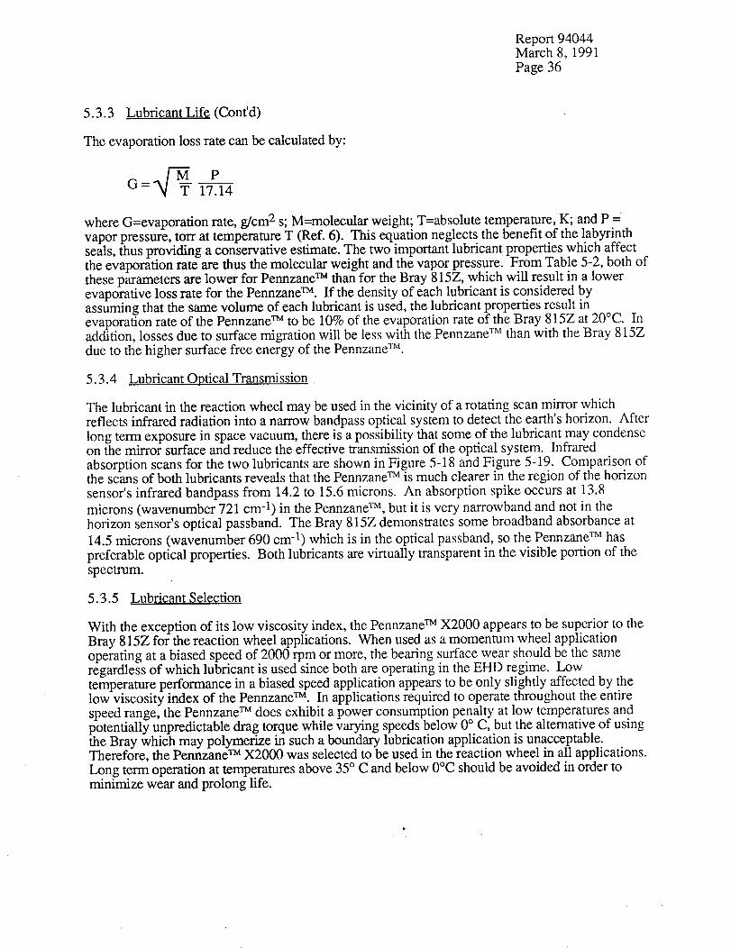
5.3.3 Lubricant Life (Confd)
The evaporation loss rate can be calculated by:
pG = 17_14
where G=evaporation rate, g/cm 2 s; M--molecular weight; T=absolute temperature, K; and P =
vapor pressure, torr at temperature T (Ref. 6). This equation neglects the benefit of the labyrinthseals, thus providing a conservative estimate. The two xmportant lubricant properties which affectthe evaporation rate are thus the molecular weight and the vapor pressure. From Table 5-2, both ofthese parameters are lower for Pennzane TM than for the Bray 815Z, which will result in a lowerevaporative loss rate for the Pennzane TM. If the density of each lubricant is considered byassuming that the same volume of each lubricant is used, the lubricant properties result inevaporation rate of the Pennzane TM to be 10% of the evaporation rate of the Bray 815Z at 20°C. Inaddition, losses due to surface migration will be less with the Pennzane TM than with the Bray 815Z
due to the higher surface free energy of the Pennzane TM.
5.3.4 Lubricant Optical Transmission
The lubricant in the reaction wheel may be used in the vicinity of a rotating scan mirror whichreflects infrared radiation into a narrow bandpass optical system to detect the earth's horizon. After
long term exposure in space vacuum, there is a possibility that some of the lubricant may condenseon the mirror surface and reduce the effective transmission of the optical system. Infrared
absorption scans for the two lubricants are shown in Figure 5-18 and Figure 5-19. Comparison ofthe scans of both lubricants reveals that the Pennzane TM is much clearer in the region of the horizon
sensor's infrared bandpass from 14.2 to 15.6 microns. An absorption spike occurs at 13.8
microns (wavenumber 721 cm -1) in the Pennzane TM, but it is very narrowband and not in thehorizon sensor's optical passband. The Bray 815Z demonstrates some broadband absorbance at
14.5 microns (wavenumber 690 cm -1) which is in the optical passband, so the Pennzane TM has
preferable optical properties. Both lubricants are virtually transparent in the visible portion of the
spectrum.
5.3.5 Lubricant Selection
With the exception of its low viscosity index, the Pennzane TM X2000 appears to be superior to the
Bray 815Z for the reaction wheel applications. When used as a momentum wheel applicationoperating at a biased speed of 2000 rpm or more, the bearing surface wear should be the sameregardless of which lubricant is used since both are operating in the EHD regime. Lowtemperature performance in a biased speed application appears to be only slightly affected by thelow viscosity index of the Pennzane TM. In applications required to operate throughout the entire
speed range, the Pennzane TM does exhibit a power consumption penalty at low temperatures andpotentially unpredictable drag torque while varying speeds below 0 ° C, but the alternative of usingthe Bray which may polymerize in such a boundary lubrication application is unacceptable.Therefore, the Pennzane TM X2000 was selected to be used in the reaction wheel in all applications.
Long term operation at temperatures above 35 ° C and below 0°C should be avoided in order tominimize wear and prolong life.

0 ,,.-_
&o "T_4. --
i
c:Q "tOO --
& "EOEI --ll_
I qll_i =a (0
Q
00
Y
zN
I ilUI -'-'i_
u
)I
¢..>
°
O
!"
0
!,
o.
i
N
0
X
L',,1
©
°r.,_
0000 "_ 0C30_ "It OODZ "1 _
M_V
ooolr "o oooo "o
z
.I
O
<b_
d_

Report 94044March 8, 1991
Page 38
5.4 Motor.
An integral direct drive motor is required in the reaction wheel to spin up the flywheel, maintainspeed, and provide instantaneous reaction torque to the spacecraft.
5.4.1 Motor Type
The two candidate motor types which do not require contacting brushes are AC induction motorsand brushless DC motors.
The AC induction motor has the advantage that it involves no permanent magnets, and therefore
has no drag torque from eddy current losses, and no cogging. The induction motor is driven openloop by a simple circuit consisting of two square wave current sources 90 ° out of phase. There isno low frequency torque tipple, and the speed is conveniently limited by the synchronousfrequency of the driver. This type of motor has been used successfully in many reaction wheelapplications. The disadvantages of the induction motor are that the torque is not linear with respectto rotation speed, and the efficiency is extremely low. The linearity is desirable, but notnecessarily critical, since it has been successfully dealt with in numerous attitude control systems.However, the high priority placed on power consumption in the tradeoff considerations deals theinduction motor a severe blow.
Most of the more recent reaction wheel designs employ a brushless DC motor due to its higher
efficiency and linear torque. Hall sensors are typically employed for discrete commutation, whichserve a second function of providing a tachometer signal. This type of motor is more powerefficient than the induction motor, resulting also in a lower stator mass required to conduct waste
heat away from the windings. One disadvantage is a slightly more complex motor driver requiringrotor position feedback information for commutation. This can be accomplished with the use ofhall sensors, optical switches or eddy current probes. The fact that this type of information isrequired for tachometer feedback from the wheel for the attitude control system turns this into anadvantage. The brushless DC motor does have significant torque ripple, at a frequencycorresponding to the commutation rate, which is the number of poles multiplied by the number ofphases and the rotation rate. For a two phase, six pole motor operating at 500 rpm, thiscorresponds to a torque ripple frequency of 100 Hz, which could be low enough to causeundesirable torque disturbances on some spacecraft. The presence of rotating permanent magnetsin the brushless DC motor design also produces cogging and eddy current drag torque.
During the development of magnetic beatings for spaceflight applications, an ironless armaturebrushless DC motor was developed by Phil Studer at NASA GSFC and Henry MacLanski ofMacBar mechanisms. The ironless armature motor was required for the magnetic bearings for itscharacteristic of no radial forces, which can be a significant destabilizing force in the active
magnetic bearing control system. In a reaction wheel application, the ironless armature motor isideal, since it minimizes the overall system weight by placing all of the motor iron on the flywheel.

Report94044March8, 1991Page39
5.4.1 Motor Type (Cont')
A cross section of an ironless armature motor is shown in Figure 5-20. It consists of a thin
armature which supports the windings, with a set of magnets on one side and a flux return path onthe other side. The result is a motor which exhibits no cogging or eddy current drag, since there is
no relative movement between the magnets and the iron flux return ring. Because of this, the ironcomponents need not be laminated, which reduces the cost of these parts. The efficiency of anironless armature motor is maximized by utilizing the largest possible diameter, since the number
of poles is increased and torque radius is increased. By increasing the number of poles, theresolution of the tachometer signal from the commutation signal is also increased. Hence, theironless armature motor is ideal for the reaction wheel drive, by being both power and weight
efficient. In typical applications, the ironless armature motor is more massive than a comparableconventional brushless DC motor, because the magnet gap is extremely large to accommodate a
thin section armature inserted into the gap with clearance on both sides. This enlarged gap.requires
large magnets and heavier low reluctance iron components to compensate for the increase mmagnetic gap. In the reaction wheel application, however, the added weight is where it would be
required anyway to full'ill the flywheel inertia requirements.
5.4.2 Motor Selection
The unique combination of lowest power consumption and lowest weight makes the ironlessarmature motor the obvious choice. This unlikely result occurs once in a lifetime in tradeoff
analyses, so it would be a shame to not take advantage of this configuration. The ironless armaturemotor is not new in the reaction wheel arena. European manufacturers of spaceflight reaction
wheels have been using ironless armature motors in their designs for many years.
Initial estimates predicted a higher cost for procurement of the ironless armature motor, but thiswas offset by the drastic weight savings over conventional motors. The weight savings was on theorder of a pound, which can translate to several thousand dollars in launch costs on even the mosteconomical launch vehicles. However, actual quotes to manufacture production quantities of flight
quality motors were much higher than expected, in the $8K - $12K range, resulting in animpossible price tag for a low-cost reaction wheel. The high cost was primarily due to thefabrication complexity of the armature, due to the hand labor for winding and the numerousspaceflight quality solder connections required.
Rather than discard the ironless motor design, a possible solution was presented to MacBarMechanisms to reduce the recurring costs. Most commercial ironless motors have a printed circuitarmature in a disk configuration. If it were possible to manufacture the armature windings on aflexible printed circuit and laminate it to a fiberglass epoxy ring, the recurring costs would becompetitive with conventional motors, and the reliability would also be enhanced. MacBar agreedthat it could be done, but that they did not have enough experience with flexible printed circuits to
take on the job. Other commercial printed circuit motor manufacturers did not want to bother withthe unconventional configuration for a short-order design.
A make/buy decision was made at ITHACO to design and build the ironless armature motor in-house. MacBar Mechanisms was solicited to perform the electrical and magnetic design of the
motor on a consulting basis, and the mechanical packaging of the armature and the fabrication was
performed at ITHACO.

Report94044March8, 1991Page40
,_ AluminumFlywheel
A
x Return Iron
Printed Circuit
Armature (Stator)
p_
' Permanent Magnet
Back Iron Ring
Figure 5-20: The Ironless Armature Brushless DC Motor is an optimum drive for momentum/
reaction wheels due to its unique combination of high efficiency and high
inertia/weight

Report94044March8, 1991Page41
5.5 Tachometer
A tachometer signal is required for speed and direction of rotation feedback from the reactionwheel. Attitude control systems can use either an analog tachometer voltage proportional to speed,or a digital tachometer of a square wave with a frequency proportional to speed. The analogtachometer can be easily derived from the digital type of tachometer, so the logical type oftachometer is the digital type. The incorporation of a digital tachometer with an analog tachometercircuit as an option also lets the customer select the preferred tachometer signal for his system. Inaddition, a discrete digital signal is required to commutate the brushless DC motor.
Digital tachometer signals are commonly generated by magnetic pickups, eddy current probes, hallgenerators, and optical switches.
Magnetic pickups are rugged, reliable, passive devices, used commonly in momentum wheelapplications operating at a biased speed. However, the amplitude of the signal generated fromthese devices is proportional to speed, so the signal degrades as the speed is reduced. This is not
compatible with a reaction wheel application requiring bi-directional operation through zero speed.
Signals derived from eddy current probes are insensitive to the speed of the flywheel, but require acomplex, unreliable oscillator circuit to stimulate the eddy current effect. The accuracy of the eddycurrent systems is low and the power consumption is high relative to other devices. A machinedgear in the flywheel is required to stimulate the eddy current probe, which increases manufacturingCOSTS.
Optical switches are also used commonly for reaction wheel tachometers, especially where highresolution and high accuracy is desired. Light from an LED is directed towards a phototransistorand interrupted by a shutter or a alternately reflecting/absorbing surface. The simplicity of thisdesign ranks it very high, but the high power consumption required to illuminate the LED is toohigh for an ultra-low power consumption design.
Hall generators are commonly employed for commutation of brushless DC motor. The hallgenerators can be stimulated directly from the permanent magnets in the motor, so a separate gearor code wheel is not required. The phasing of the hall sensors signals when stimulated by theactual motor magnets is exactly correct for commutation, eliminating any alignment procedurerequired to clock a separate gear to the motor. The circuitry to bias the hall sensors is very simple,requiring only a constant current source. The sinusoidal output of the hall sensors when excited bythe motor magnets can be easily processed into discrete commutation and digital tachometer signalswith a simple comparator circuit.
5.5.1 Tachometer Selection
The hall generators were selected for the reaction wheel tachometer because of their low cost andthe fact that their simplicity eliminated the need for many additional parts. They can be integrated
directly into the armature assembly to minimize the packaging requirements for the commutationand tachometer components.

Report94044March8, 1991Page42
5.6 M01;0r Driver
5.6.1 Motor Driver Design Goals
Goals for the motor driver design echo those for the entire reaction wheel. These goals aresummarized as follows:
Extremely low power consumption, high efficiency (less that 0.5 Watt at 1000 rpm)
Simple ReversingMotor Drive Down Capability
Operation on 6 V Power Bus (0-2500 rpm Operation)Adaptability to 28 V Power Bus (0-5100 rpm Operation)Motor Control via Torque CommandReturn of Stored Energy to the Power BusLow Cost
In order to fulfill the design goal for minimum power consumption, the motor driver had to be as
power efficient as possible. The design specification of less than 1 Watt of power consumption at1000 rpm leaves less than 0.5 Watt for the motor driver when the bearings and motor consumeover 0.5 Watt under normal conditions. In order to fulfill a variety of applications, bi-directional
torque and speed capability was required, and simple reversing of torque and speed was desired.For the sake of convenience at the attitude control system level, a motor torque control proportional
to an analog torque command was desired, with torque linearity an asset, but not a rigidspecification. Return of stored energy in the flywheel to the power bus was also a desirableoption. The 6 volt bus on the XSAT satellite dictated that the motor driver be designed for thisvoltage, but because of market demands, it was deemed extremely desirable to be able to adapt themotor driver to operate with a 28 volt bus as an option.
5.6.2 Motor Characteristics
The electromagnetic requirements for the design of the ironless armature motor resulted in anunconventional design with the following basic parameters:
Motor Type:Winding Resistance:Winding Inductance:Position Sensors:Back EMF:No. of Poles:
3 phase, delta connected brushless DC0.1f_
35 IxHy3 hall sensors
0.00167 V/rpm36
The O.1 ohm winding resistance of the motor indicates that connecting the windings directlyacross the power bus would result in a 50 amp current. Consequently, the driver design must haveinstantaneous control of motor current at all times.

Report94044March 8, 1991
Page 43
5.6.3 Driver Tooology_
A functional block diagram of the motor driver circuit is shown in Figure 5-21.
5.6.3.1 Pow¢r Bridge
The efficiency requirements mandated a directly switched pulse width modulated three-phasebridge. Due to the extremely low winding inductance, small discrete inductors were added inseries with the bridge outputs. These inductors also serve to reduce RF emissions from the driver.
Because of the low 6 volt bus voltage, inefficiencies from diode forward drops and bipolartransistor base drive requirements could not be tolerated. Consequently, the three-phase bridge isconstructed from power MOSFETS. In addition to reducing drive power requirements, diodedrops from the bridge were eliminated, since, with proper gate drive, the MOSFETs act assynchronous rectifiers.
5.6.3.2 Commutation
In order to meet the power and performance requirements the commutation control circuitry is
implemented from discrete CMOS digital and low power opamps and comparators.
For simplicity and low cost, a conventional "square wave drive" scheme was selected. This resultsin a textbook torque ripple of 15%, which has been judged not to be significant in the application,since the steady state torque is very low and the large number of poles results in a fairly hightorque ripple frequency. Motor current control was chosen as an approximation of output torquecontrol. This is compatible with typical momentum bias Attitude Control Systems.
Conventional BDC drivers operate in either "current mode" (two quadrant) or "voltage mode" (fourquadrant). Current mode operation is simpler to implement and slightly more efficient than voltagemode, however, the following limitations prevented its use:
Motor Braking is difficult and unsafe, especially with a low resistance winding.Bi-directional operation requires a "direction command".The current mode driver will not return motor kinetic energy to the bus.
Use of the bridge MOSFETS as synchronous rectifiers is not straightforward, limiting efficiency
potential.
Consequently, a 4-quadrant drive scheme was selected. This scheme allows simple monitoringand control of the bridge current under all conditions as well as seamless reversing and full four-quadrant torque controlled servomotor operation. When the motor is driven down, the bridge actsas a boost converter, and delivers the motor kinetic energy safely to the power bus instead of
dissipating it in the bridge or the motor windings.
5.6.3.3 P01se Width Modulation
A hysteresis - type "pulse width modulator (PWM)" provides coherent and instantaneous controlof the motor winding current. The PWM operating frequency is essentially proportional to busvoltage. Components are selected so that the PWM nominal frequency is close to 20 KHz.

(/o
t_
°°
!
t_.O
_,._°
!
REGUI_TEDPOWER!
BUS VOLT EMIFILTER
w=
TORQUE CMD 1
TORQUE CMD 2 _-_ ÷ r +
TORQUE CMD TEST 1
TORQUE CMD TEST 2_-
!
TORQUE CMD RTN
!
TORQUE CMD RTN
DRIVESIGNAL
!
I
CURRENT
TELEMETRY
I
!
!
$
!
!
cp1 JMOTOR _02
J
POWER _03 FDRIVER
COMMUTATION m
DECODER !
(COMB. LOGIC) I
it
!
,j
!
!TACH
CIRCUITRY
!
I
!
!
DRIVER _ I--'_
TEMP LOGIC I''_
TLMY CIRCUITRY
MOTOR DRIVER ............ j
DRIVER TEMP
TLMY
CURRENT TLMY 1
CURRENT TLMY 2
CURRENT TLMY REF
.jj ,._|
ANALOG TACH l
ANALOG TACH 2
DIGITAL TACH SIGNAL I
DIGITAL TACH SIGNAL 2
TACH DIRECTION I
TACH DIRECTION 2
LPROCESSING
MOTOR
CO

Report 94044March 8, 1991
Page 45
5.6.3.4 Supplementary_ Features
5.6.3.4.1 Ballast Circuit
Many motor driver users cannot absorb the negative bus current obtained during motor drivedown. The Ballast circuit is an optional current shunt that sinks all negative bus current generated
by the motor driver to the power return.
5.6.3.4.2 T¢lemetries
The motor driver was designed for maximum versatility by offering a wide variety of telemetries.
5.6.3.4.2.1 Temperature Telemetry_
One conditioned thermistor is located on the motor driver circuit board. No thermistor was
designed into the reaction wheel itself in order to maintain modularity within the wheel housing,for the incorporation of a thermistor requires a solder operation at the top assembly which must bedesoldered if the unit is ever disassembled. The configuration of any reaction wheel does notallow instrumentation of both bearings without dual connectors. The ITHACO Reaction Wheelconfiguration does allow for a thermistor to be added to the motor side of the wheel with minor
impact. However, its value is questioned.
The primary function of locating a thermistor on the bearing is to monitor the health of the bearing.However, this can be monitored with more precision using the motor current telemetry. Thetemperature telemetry data is clouded by changes in ambient temperature, high thermal timeconstants, and low resolution. A thermistor within the wheel would be located directly on the
bearing cartridge on the motor side. Due to the low thermal resistance between the bearingcartridge and the mounting surface, the resolution of the thermistor would be less than 0.25 voltsper oz-in of increase in bearing drag torque. Temperature rise in the opposite bearing would beimperceptible since the bearings are practically decoupled from each other by the low thermalconductivity of the shaft. However, the same one oz-in of drag torque increase in either bearingwould result in more than a 0.5 volt differential in the motor current telemetry while operating at a
steady state speed of 2000 rpm.
The tradeoffs in utilizing the thermistor interface within the motor housing involve sacrificingredundancy on the +5 V going to the wheel assembly, and sacrificing the redundancy on thechassis ground connection to the wheel, as well as sacrificing the thermistor located on the motordriver card. As a result, the baseline design utilizes only the thermistor on the motor driver, withan option to relocate the thermistor within the reaction wheel housing with the described sacrifices.
5.6.3.4.2.2 Speed/Direction of Rotation Telemetry_
Each hall sensor provides an 18 pulse per revolution digital signal for speed information. Therelative phasing between any two hall sensors is used in a phase detector circuit to generate a rotordirection of rotation flag. Combining the edges from the three hall sensors with digital logic resultsin a 54 pulse per revolution digital tachometer signal. The same information is processed to delivera complementary bipolar analog tachometer.

Report94044March8, 1991Page46
5.6.3.4.2.3 Motor Current Telemetry_
An analog signal proportional to current in the motor windings is provided, since it contains themost significant data regarding the health of the motor, motor driver, and bearings. Small changesin bearing drag torque can be detected by monitoring the steady state motor current at a specificspeed.
5.6.3.4.3 Commands
The user has access to four summed bipolar analog torque commands and a driver enablecommand.
5.6.4 Motor Driver Packaging
An effort was made to identify off the shelf motor controller and driver Hybrids and ICs whichcould be used in this driver. A market survey identified a Unitrode 3620/3622 which is a complete
motor driver in a plastic power package. The vendor has been tryin.g to successfully install thispart in high reliability packaging. The part had the following limitataons:
Quiescent Power Consumption was greater than the entire motor/driver power budget.True 4 - quadrant control was not possible.Potential efficiency using the bipolar technology was limited.Operating voltages were not compatible with the 6 V bus.
Ideally, the entire motor driver should be enclosed within the motor. Because of the discretecircuitry, and space limitations within the motor, the motor driver was designed to be installed on a6x6 circuit card compatible with ITHACO's modular packages. A portion of the circuitry wasinstalled within the motor housing on a small round circuit card required for termination of theflexible printed circuit motor windings from the ironless armature motor. The constant currentsource to power the hall sensors and the comparators required for the discrete commutation signalsare included on this circuit card.
The design of the printed circuits in the ironless armature motor allows the torque constant of themotor to be modified with simple jumper wires on the circuit board within the motor housing. Bystringing the four motor windings in series, series-parallel, or parallel, three torque scale factorscould be used, along with three back-emf constants. This allowed the versatility to use the samemotor at different bus voltages, as the back-emf constant typically limits the speed of operation.The motor driver was designed to accommodate the three winding configurations along withmultiple bus voltages by simply adjusting the motor current scale factor by component valuesubstitution on the circuit card.

Report94044March8, 1991Page47
6.0 FINAL DESIGN DESCRIPTION
The Reaction Wheel consists of an aluminum flywheel with a thermal fitted stainless steel shaftsuspended on ball bearings and driven by an ironless armature brushless DC motor. The housingstructure is made up of two symmetrical aluminum plates which are separated by a cylindrical ringon the outside diameter and form a spider-web bridge to support the rotor. As is common withmany flight proven reaction wheel assemblies, the housing is vented to space to minimize viscousdrag torque from the flywheel due to windage. A cross section identifying the major componentsof the assembly is shown in Figure 6-1.
6.1 Ball Bearing Suspension System
The flywheel is suspended by a pair of non-separable, angular contact, spring preloaded ballbearings. The inner races of the bearings are clamped onto a stainless steel shaft by spanner nuts,and the outer races are slip fit into stainless steel cartridges. A wavy washer preload springprovides a light preload to remove the axial and radial play in the bearings, and accommodate theaxial thermal expansion of the shaft and housing. The two bearing cartridges are identical, and arealigned with a similar slip fit with the aluminum housing. Assembly machining of the borethrough the housing ensures precision alignment of the bearings, and also provides excellentmomentum vector alignment. A sketch of the suspension system layout is shown in Figure 6-2.
The bearings are a standard R4 configuration purchased to ABEC 7 tolerances. The arrangementshown was chosen for its stability and low drag torque, since a complete suspension can beaccomplished with two bearings by preloading the bearings with a preload spring. An alternatemethod of preloading with duplex pairs requires twice the bearing count, which doubles both thepower and cost of the bearing units. The angular contact bearings employ one piece phenolic ballseparators, which do not significantly contribute to wear, and can be impregnated with a smallsupply of lubricant.
6.2 L_bricati0n System
Since the Reaction Wheel Assembly is vented to space, a low vapor pressure oil is used tominimize lubricant depletion due to outgassing. The Pennzane X2000 is a synthetic hydrocarbonwith an extremely low vapor pressure, which has demonstrated excellent boundary lubrication
capability when used with Lead Napthanate as an extreme pressure additive.
The bearings selected for ITHACO's Reaction Wheel use conventional 52100 steel races, and steelballs coated with titanium carbide (TIC) applied by chemical vapor deposition. The insolubility ofthe TiC ball coating with the steel races eliminates the microwelding during sub-EHD operation. Inaddition, the TiC coating provides an 'emergency lubrication' scheme, providing extended lifetimethroughout the entire operating speed range even after the lubricant supply is completely exhausted.An optional high capacity bearing using 440C stainless steel balls and races is available forapplications which have severe random vibration requirements.

Report 94044March 8, 1991
Page 48
ALUMINUMHOUSING
ALUMINUM
ACCESSPANEL
BEARING COVER
BALL BEARINGSUSPENSION
i
IRONLESS ARMATUREBRUSHLESS DC MOTOR
Figure 6-1: Reaction Wheel Assembly

Report 94044March 8, 1991
Page 49
PRELOAD
SPRINGLABYRINTH
SEAL
BEARING
CARTRIDGE
SHAFT NUT
BEARING
COVER
Figure 6-2: Reaction Wheel Suspension System

Report94044March8, 1991Page50
6.2 Lobricati0n System (Cont'd)
Several features are incorporated into the design of the lubrication system in order to minimize theloss of lubricant from the bearings. Close clearance labyrinth seals are used between the rotatingshaft and the bearing cartridges to restrict the flow of molecules toward the vacuum, and thesurfaces inside the bearing cartridges are coated with a thin film of the bearing oil to provide a
sacrificial oil atmosphere inside the bearing cartridge volume. This film not only serves to providethe oil atmosphere, thereby reducing the net evaporanon rate from the bearings, but it will alsoinhibit the surfaces from becoming a condenser that would rob molecules from the atmospheresurrounding the bearings. In addition, the one piece phenolic retainers are vacuum impregnatedwith bearing oil in order to serve as a small oil reservoir within the bearing volume. Anothersource of lubricant depletion from bearings is surface migration. In order to prevent this, a barrierfilm coating is placed at strategic locations near the bearings. No barrier film is used directly on thebearings, in order to avoid contamination of the bearing surfaces, which would cause non-wettingof that area resulting in a local area of high wear.
6.3 Motor
The Reaction Wheel motor is driven by a discretely commutated, ironless armature, brushless DCmotor. Maximum inertia to weight ratio is realized with the large diameter motor components andthe unique feature of the ironless armature motor which strategically places all of the mass of theiron and magnets on the rotor. Hall sensors integrated directly on the armature sense thealtemating flux field from the permanent magnets to provide commutation information for themotor driver, as well as a high resolution tachometer signal for speed and direction of rotationinformation. The motor driver is conveniently packaged in a 6" x 6" x 1" card frame, for
integrating into a modular attitude control system, or as a separate enclosed electronics box.

Report94044March8, 1991Page51
7.0 BREADBOARD UNIT MANUFACTURE
An engineering prototype of the reaction wheel was fabricated in order to validate the designdecisions and assess the manufacturability of the hardware. The following sections address theproblems encountered during the fabrication, and the resulting solutions.
7.1 Rotor Assembly Manufacture
The assembly of the rotor was basically a three part process. The first process is the thermal fittingof the shaft in the flywheel. This was successfully accomplished by heating the aluminum rotor to200°F, and cooling the shaft in liquid Nitrogen. The shaft was then placed into the central bore inthe flywheel and allowed to return to room temperature. A locking nut was then installed, torqued,
and staked with epoxy.
The installation of the magnets onto the magnet ring was performed with a special geared fixturewhich aligns the magnets relative to each other. Structural epox.y was placed on the inside diameterof the magnet ring, and the magnets were installed in the respecttve locations. Aluminum spacerswere installed between the magnets with structural epoxy. When the magnet ring was installed intothe aluminum flywheel, a film of epoxy was applied to the bore diameter in the flywheel and themagnet ring was inserted. This process forced a small spot of excess epoxy to form in the motorgap, which was later detected during a test where the unit was being run at high speed with highdrag torque bearings. The motor armature heated slightly and caused interference between theepoxy and the motor armature. The friction heating from the interference caused local expansion ofthe armature which increased the friction and the heating, resulting in a seizure of the motor, anddestruction of the windings in that area. This process was modified for subsequent builds of the
rotor by applying the epoxy to the outside diameter of the magnet ring, rather than the insidediameter of the bore, so that any excess epoxy is forced out the bottom of the rotor where it can beeasily cleaned off. Additional inspection steps were also incorporated to ensure sufficient motorclearance. The rotor was sent to Schenck Trebel for precision balancing.
7.2 Stator Manufacture
The first motor stator was assembled from a fiberglass epoxy ring, an aluminum base ring, and
three Kapton flexprints with a single zig-zag conductor for an equivalent of one turn per pole, perphase. The flexprints were bonded to the fiberglass epoxy ring with transfer film adhesive, andthe assembled armature was bonded into the aluminum base ring with epoxy. Hall sensors were
installed using transfer film adhesive, and all components were terminated on a piece of vectorboard attached to the inside diameter of the aluminum base ring.
This preliminary assembly was installed in the housing with the rotor and bearings, and integratedwith the breadboard motor driver. The performance seemed to indicate the presence of a source of
high drag torque increasing proportional to speed. Investigation revealed that the losses werecaused by eddy currents in the motor windings themselves. The copper conductors were 0.1inches wide, resulting in a large surface area for circulating eddy currents from the dynamic
magnetic fields of the motor. This was corrected by striating the conductors into 8 parallelconductors. By terminating the eight conductors at four separate pads, the option was opened to
adjust the motor torque scale factor and back emf constant by simply modifying the terminationjumpers on the flexprints. The windings could be connected all in parallel, in series parallel, or allin series to result in three different motor designs.

Report94044March8, 1991Page52
7.2 Statqr Manufacture (Confd)
The flexprints were redesigned and assembled onto a fiberglass epoxy armature support. In orderto minimize the eddy current drag torque due to leakage flux from the motor magnets in thealuminum stator base ring, the material for the base ring was changed to fiberglass epoxy. Thelow electrical impedance of the motor windings results in very little heat dissipation in thewindings, so the low thermal conductivity of the fiberglass epoxy was not considered to bedetrimental. The striated flexprints effectively eliminated the eddy current drag torque.
7.3 Breadboard Unit Confi_ration
The only change required in the configuration of the engineering breadboard unit reaction wheelassembly was the fabrication of a new motor armature when excess epoxy in the motor gap causedinterference and subsequent destruction of the flexprint motor windings. Various bearings havebeen alternately installed in the unit for engineering testing. Currently the unit consists ofmechanical components dimensionally the same as flight hardware, a vector board within thewheel housing for termination of the motor winding flexprint assemblies and hall sensors, and abreadboard motor driver on vector board. The breadboard motor driver and the reaction wheel are
interconnected with a 15 pin sub-miniature D connector pigtailed off of the termination vectorboard in the motor housing, and three pigtailed banana jacks from each node of the delta
configured motor windings.

Report94044March8, 1991Page53
8.0 BREADBOARD UNIT TEST DATA
The development testing performed on the breadboard engineering unit consisted of a vibrationmodal survey of the structure, measurement of the external magnetic field, extensive testing oflubricants and bearings, and performance characterization.
8.1
In order to verify the predicted dynamic characteristics of the reaction wheel structure a modalsurvey was performed on the breadboard engineering unit. The resonant frequencies andtransmissibilities of the rotor assembly are critical in order to accurately predict the statistical
bearing loads during random vibration exposure. A Small analytical vibration facility at Comell
University was used for the testing.
Using a constant white noise spectrum on the order of 0.001 g2/Hz from 10 to 1000 Hz, transferfunctions were obtained in several hardware configurations. Response accelerometers were placed
directly on the rim of the rotor. The axial response to an axial input is shown in Figure 8-1. Aclassic response of a single degree of freedom system is apparent, with a resonance at 89.13 Hz.This correlates very well with the predicted resonant frequency of 100 Hz. The measuredtransmissibility of 5.9 also corresponds to a predicted value of 5.6, based on the square root of theresonant frequency. The radial response to a radial input is shown in Figure 8-2. The radialresonance of 365.2 Hz also corresponds with the designed resonant frequency of 350 Hz, and themeasured transrnissibility of 10.5 shows some conservatism in the estimated value of 14. Figure
8-3 shows the axial response to a radial input, which shows the rocking mode resonance to appearat 129.6 Hz. This is very close to the predicted frequency of 122 Hz. Figure 8-4 shows the
phasing of opposite ends of the rotor to verify the rocking mode is indeed in the neighborhood of130 Hz, by highlighting the phase shift which occurs at that frequency.
The measurements taken were very close the the responses predicted by the structural math model.The successful results enable confident prediction of bearings loads and structural factors of safety,and form a baseline from which the effect of design iterations and modifications can be
extrapolated.
8.2 Drag Torque Data
Drag torque measurements were performed throughout the development testing on the breadboardengineering unit. The drag torque is the best measurement of the health of the unit and a primarycontributor to the performance of the hardware.
The drag torque is determined by measuring the rate of decay of the rotor speed. Using a computeror a stopwatch for data acquisition, the rotor speed vs. time is measured. From these data, the
drag torque is determined from the following relationship:
Drag Torque (oz-in)=I • (rpml-rpm2) • 20.11/Atime
where: I = Flywheel Inertia (ft-lbf-sec 2)rpml = first speed readingrpm2 = second speed readingAtime = time between speed readings

_'0",
"[A 0
I I i II I I I I
i
I
OI
i
I
i
I
I
i
I

,,
B
0
0
I
t_
0
X_365. 2-. HzYo--lO. 5018
FREQ RESP
20"0 F
Lo 9
MoSI
80. 0
I0
lOAv 9 O%Ovlp
Lo B Hz
Ovl&2
Ik
tm oo _:_

N>O
NO3
N
0
N__HII 0
X>-
Report 94044March 8, 1991
Page 56
nr-.t
>0
0
I
/
Jllll I I I I I I
m
X,--4
OE
6r'q
NT
:0_3
J
0
Figure 8-3: Random Vibration Transfer Function Radial Input - Axial Response

#
_,_o
0b.-_°
E0
=r
(JQ
X=132. 5g HzYe_179. 805
FREQ RESP
180
45.0
/DiM
D_9
--180
Fxd Y iO Hz
I I I | 1lk
o 0
"J oo _
_0_0._

Report 94044March 8, 1991Page 58
8.2 Drag Torque Data (Cont'd)
Drag torque testing was performed in order to compare the performance of the two types ofbearings used in the design, and to evaluate lubricants in a lubricant selection tradeoff. Some ofthe more relevant drag torque curves are presented.
Figure 8-5 shows a baseline drag torque curve taken in air with the MPB bearings with TiC coated
bails. In order to quantify the proportion of the drag torque due to the viscosi_ of the lubricant thebearings were assembled with no lubricant. Figure 8-6 shows the drag torque m vacuum with nolubricant. A subsequent drag torque curve with a small amount of Bray 815Z lubricant in thebearings is shown in Figure 8-7. This shows that in the open conformance TiC coated bearings,the lubricant is not a significant contributor to drag torque, resulting in only a 15% increase inoverall drag torque. A drag torque curve of the Barden high capacity bearings with the samequantity of Bray 815Z lubricant is shown in Figure 8-8. The close conformity of the high capacitybearings results in a significant drag torque increase over the standard MPB configurationbearings.
Extensive drag torque testing was performed during the tradeoff study between the Bray 815Z andthe Pennzane TM X2000 lubricants. These data are presented in the lubricant tradeoff in Section 5.3
of this report.
8.3 Beating EHD Film Testing
The design and analysis of long life bearing systems has been greatly influenced byelastohydrodynamic (EHD) theory. A rotation speed at which the asperities on the balls and racesare separated by a thin film of high pressure lubricant has been referred to as the EHD liftoff speed.If a pair of lightly loaded bearings is operated above this speed, there is virtually no wear on thebearing surfaces. The bearing will then last as long as it is properly lubricated. In order tomeasure this critical speed, a simple test is performed where the electrical resistance is measuredthrough the bearings. When the separation occurs, the resistance goes towards infinity. This typeof measurement was made on both types of bearings used in the reaction wheel design and with thetwo lubricants in the final lubricant tradeoff analysis. The relationship of EHD liftoff speed vs.
temperature was characterized for the two candidate lubricants, and these data are presented inSection 5.3.1 of this report.
Typical EHD liftoff charts obtained on the breadboard engineering unit with both types of bearingsand the two candidate lubricants are shown in Figures 8-9 to 8-12.
8.4 External Magneti_ Field Measurements
A test measuring the external magnetic field generated by the permanent magnets within thereaction wheel motor revealed a once per revolution alternating flux field which is attributed to theasymmetry of the strength of the individual motor magnets. The measurements were taken with asingle axis magnetometer nulled to the earth's magnetic field. A once per revolution field wasmeasured with a maximum value of .04 milligauss at a distance of one meter from the RWA. This
is less than the .2 milligauss goal established in the RWA specification. The maximum fieldincreases to .4 milligauss at a distance of 50 cm. Graphs of the data taken on the breadboardengineering unit are shown in Figure 8-13 and 8-14.

Report94044March8, 1991Page59
TORQUE vs. RPM
2.5
.._,0
I
!.!
o L .5
_L
-.6,-"+ l .0
| ....
•<Fil'F;;:F't.1,--.i>
, | :
4,......
"-. ,
I ' ' ' I ' i ' I
"-,hi-,. -
" I-, .k t,. 4, I,=+._
............................................................. ...........................
I
.dr., ,:_;t:, ,{t:,_.'-.-::t -,':}L:'" .';5'
..... ::_""+<BZ[-..........
'"l_j
1 t i t t _ I
. .:{!:t:, ..,y.-,
Figure 8-5: Drag Torque in Air - MPB Bearing
r.,
l:
i-.4
O
'_U'__'-"--_7"--"_'_--'"i---'1_ / _ ,__ ......I-_L I i t
I I ....f.....! !--t--- I !
.5 _---i_-,_, -_T,-,b_ .... _---_----b----i ..........,I ' ÷,,4i.,,,.-u.,i t 11 I
I I I I "_"'I_,.-_..,' II ! I
I • '---I---*--_=--'.....-_ II , I ,-I.-I"r-, I , o=.
t-.... ,I------i .... i-.... l----i----i----_'_t"_:_;;-_tTT ......P-................! I ! ! 1 1 '_i_%..,. !!.......... L___.L ......... t-- . 4,- ..... -I-- .... L-_.---L--_,_ ......
/ ! • t .... [ ........ I ! / t _"_4_.,.
I .... _..... ]----+_---A.....-4--..... -::_
--rT-'_--T-I
iI
I
.............
.... {:_.:, "" ':_", ':;, . !::1::, ..':L, ,._::1::, . ,:_;i;i':' ¢, ..':.L,F.:i='_'._,:,':?' ,.-_i'_:' ,:_v.' ,.,:n ,:,.,.,,:,_ ....::;... ,:::, _.,.- _::S;- ..,:i.:." ,,4]-:' .....:,u,._,-:_;," ....... ,.':_i_:'• " "!t"' '-:, '?.:" .. %"_ ..- "
Figure 8-6: Drag Torque of Dry MPB Bearing in Vacuum

Report94044March8, 1991Page60
k.
i"I"4
o
,'r,
it.
I'--
.s l-._ _..+_' :_-,t%
. .'--!
I
I] ' ,
........ l,, ,J ........_L__S
RF'_-i.-_.',lq:"..,:._ii:_i_:,,,.,:ti_:' t;:li:t:'':b _..':-::1_:'.,.11_.',1::' ...,"::_i'I:'...... ,_i,1::' ..,:3:i:"" .,:_!,,..,..',T:'..*.:,-""""::b<::i" .,.:..... :," ":;" '?.--' "_.. "[:':'- ....."
Figure 8-7: Drag Torque of TiC Bearings Lubricated With --15 mg of Bray 815Z in Vacuum
I
TH
C,
at..
r-,
i..i
t._i .....
.r5
___ i
' i : I P--- -I---"-_ _+_I1
• !
{, I t....!....I.........I....I....i
4"++-,- I.
"_a-,++
_n't
\\
....., ,-'i1::' _::!::;" _.':_:, -'.", j_::"" ,..,.y.," .{t:," ,:":..-:_ ,':1::;" _,._ " 4..-,- -... . .... , .'_." ::,. .. ,
Figure 8-8: Drag Torque of Barden Bearings Lubricated With =20 mg of Bray 815Z in Vacuum

Report94044March8, 1991Page61
Figure 8-9: Bearing Resistor Vs. SpeedBarden SFR40H81 BearingPennzane TM X2000 Lubricant
Figure 8-10: Bearing Resistor Vs. SpeedBarden SFR48X1 BearingBray 8152 Lubricant

• . .z
[ ......
2/o_: ............... :...............
Report 94044March 8, 1991Page 62
I
-l_ ,_,,4 .............
C3_
....
I!.I_ ............
! t+o,
t
i
t
i'°',.-, /i hoo
Figure 8-12: MPB CR4FM7 BearingBray 8152 Lubricant

Report 94044March 8, 1991
Page 63
Y
r_
10
0.1
0.01
10
Figure 8-13:
I
I
I
iI
I
III
100
DISTANCE FROM TOP OF RWA = Y
RWA External Magnetic Field (Axial)
1000
10
Ev
r,t2
¢2
.
0°1 "
Figure 8-14:
0.01 -
10
DISTANCE FROM RWA OD (cm) = X
RWA External Magnetic Field (Radial)
100

Report 94044March 8, 1991Page 64
8.5 Power Consumption Measurements
Power consumption tests on the breadboard engineering unit consisted of steady state powerconsumption measurements in vacuum, and peak power measurements. Figure 8-15 shows themeasured steady state power consumption as a function of speed with the MPB bearings and theBarden high capacity bearings. The overall power consumption is the combined power from thebus and the +15 V, -15 V and +5 V secondary power supplies. The power consumptionspecification of less than 1 Watt total for the reaction wheel and motor driver was met with the
MPB bearings, and nearly met with the Barden bearings. The overall efficiency.increases withload and speed, typical of a low torque motor, as the quiescent power consumpUon of 0.5 Wattbecomes a smaller percentage of the total load. The overall efficiency of the reaction wheel andmotor driver approaches a phenomenal 90% at 6000 rpm. At lower speeds, the efficiency is moreon the order of 60% to 70%.
The peak power consumption occurs when full torque is commanded. Figure 8-16 showsmeasurements taken of the power consumption from the bus during a full torque acceleration of therotor.
8.6 Acceptance Test Plan
A test plan to be used in the acceptance testing of flight hardware was prepared which specifiedcritical tests for the most effective screening of defects and unacceptable performance. The planned
test sequence includes a thermal vacuum test which includes all performance testing, and anexposure to random vibration. Functional checks which acquire relative health check data areperformed in air before and after the thermal vacuum test and random vibration. The followingoutline consists of summary descriptions of the testing and presents the suggested sequence.
8.6.1 Functional Test
A Functional Test is performed to verify healthy operation of the RWA prior to and followingenvironmental exposures, and during initial checkout of the assembled RWA. This type of test canalso be referred to as a 'health check', since it only verifies proper operation, but does not
thoroughly check every performance requirement over the entire range of voltages or temperature.
A Functional Test is performed prior to conformal coating and close up of the RWA measuringrun-up time, peak power, drag torque, tachometer phasing, and direction of rotation. TheFunctional Test can be performed on a lab bench in ambient conditions.
8.6.2 P0rfdrmance Test
A Performance Test is completed to assure that the RWA meets the performance specificationsthroughout the range of input bus voltages and over a range of ambient temperatures. The RWA isnot hermetically sealed, so on orbit the drag torque on the flywheel due to windage will beeliminated. In order to get an accurate measurement of the performance of the RWA, the tests needto be performed in a vacuum. This is accomplished by performing the tests in a thermal vacuumchamber. The critical performance parameters are measured in vacuum at room temperature and athigh and low temperature extremes. This testing also constitutes an environmental exposure tothermal vacuum.

Report94044March8, 1991Page65
7,
6,
86
2,
1'
I000 2000 3000 4000 5000
STEADY STATE SPEED (RFM)
I . MPB BEARING D BARDEN BEARING I
Figure 8-15: Steady State Power Vs. Speed
2C.
18'
14,
12,
g_
I000 1500 21)00 2500 300C 3500 4000 4500 5000
ROTOR SPEED (RPM)
,11
Figure 8-16: Peak Power Consumption Vs. Speed (5 oz-in Motor Torque)
6000
5500

Report 94044March 8, 1991
Page 66
8.6.2 P_rfgrmance Test (Cont'd)
The performance test will include run-up time, peak power, steady state power, motor torquescale factor, and drag torque in both the CW and CCW directions. These tests are performed atthe nominal bus voltage. At the low and high temperature extremes, the same tests are run atnominal bus voltage and the bus voltage extremes. The testing done at these extremes representsthe worst case combined operating conditions.
8.6.3 Burn-In
Following the performance testing, an additional 3 cycles of thermal vacuum temperature cyclingis performed to accumulate running time at the high and low temperature extremes. A roomtemperature performance test is performed at the end of the thermal vacuum temperature cycling.
8.6.4 Random Vibration
Random vibration exposure to the appropriate random vibration spectrum will be performed. Afunctional test is performed prior to and following the vibration exposure.

Report94044March8, 1991Page67
9.0 PHASE III STATUS
The SBIR successfully transitioned into Phase Ill development with a contract to deliver the firstflight Reaction Wheel Assembly to the University of Bremen in Germany, which will fly onBREMSAT, a small microgravity experiment to be launched from a Get Away Special cannister ona space shuttle mission. Production on this unit is nearing completion. A contract has also beenawarded to deliver a Reaction Wheel Assembly and two SCANWHEELs for the Air Force STEP(Space Test Experiment Platform) mission, with follow on contracts imminent for this series ofsmall satellites. ITHACO has also intemaUy funded a life test of the Reaction Wheel Assembly
which is currently accumulating operating time.
The design of a larger version of the reaction wheel is underway, under a contract with SpaceIndustries, Inc., for an attitude control system for the Wake Shield Facility, which is a free flyingspacecraft delivered to orbit by the Space Shuttle and retrieved on a single mission. This hardwareto be delivered on this program includes a 5 ft-lbf-sec SCANWHEEL operating at 2000 rpm and asupplementary 15 ft-lbf-sec reaction wheel operating at 6000 rpm.
Potential spacecraft which have baselined the reaction wheel or SCANWHEEL include APEX,SeaStar and SeaWiffs with Orbital Sciences Corporation, and IRIDIUM with Motorola. Thesemissions generally fall into the category of a new breed of small, low cost satellites requiring lowcost, short lead time, proven attitude control systems. The Modular Attitude Determination andControl System (MADACS) developed by ITHACO utilizing the SCANWHEEL and optionalsupplementary reaction wheels has been found to satisfy the cost, power consumption, and weightrequirements for these types of missions.
10.0 CONCLUSION
The development effort did not encounter any insurmountable obstacles which would preclude thelow-cost manufacture of a low-power consumption Reaction Wheel Assembly. Simplistic andreliable techniques were employed to result in a rugged, yet efficient, design. Processes are inplace to manufacture the reaction wheel in large or small quantities, and with options for variouslevels of traceability and documentation. An interface description of the final design available foroff-the-shelf delivery of the reaction wheel is included as Appendix A.
11.0 REFERENCES
(1) Peter Conley and John J. Bohner, Experience With Synthetic Fluorinated Fluid Lubricants,Hughes Aircraft Company, Space & Communications Group, E1 Segundo, CA
(2) Bryan H. Baxter and Barry P. Hall, The Use of Perfluoroether Lubricants in UnprotectedSpace Environments, European Space Tribology Laboratory, Risley England
(3) W. Tsusaki, Test Report on B/C Actuator Life Test With Pennzane Lubricant, TRW Space
& Technology Group, June 7,1989
(4) David J Carre', The Performance of Perfluoropolyalkylether Oils under BoundaryLubrication Conditions, The Aerospace Corporation, E1 Segundo, CA
(5) ITHACO Report 94028, EHD Liftoff Speed vs. Temperature Test Data
(6) Dushman, Scientific Foundations of Vacuum Technique, Wiley

Report 94044March 8, 1991
Appendix A
APPENDIX A
ITHACO REPORT 93945, REV. A

Report 93945Revision A
March 14, 1991
RW4A28V
REACTION WHEEL ASSEMBLY
INTERFACE DESCRIPTION
Prepared by
ITHACO, Inc.735 W. Clinton St.
P.O. Box 6437
Ithaca, NY 14851-6437

Report93945RevisionAMarch14,1991Pagei
Rev.
A
Description
Revision A to Report 93945 incorporates the following changes:
Section 3.4: Second sentence was "Most hardware as designed
will tolerate approximately 104 Rad (Si).
Sections 3.6, 3.7: "Class 100 K" was "Class 10K""Class 100 K" was "class 10 K"
Section 3.7; item 2: Added "but above -50*C. ''
Section 4.1.1.3: Was "The scale factor of motor torque vs.
command voltage is projected to be nominally 0.005 N-m/V(0.71 oz-in/V). The actual Motor Torque Scale Factor will bemeasured in test."
Section 4.1.1.8: "scale factor" was "projected scale factor"
Figure 4-3: Corrected pin designations.
Table 4-1: J9-7 voltage range was: "-5 to +5 V"J2-20, J2-21 were: "SPARE"
J8-8 Impedance was "100 K_""Digital Tach 1/2" was "Digital Tach""Analog Tach 1/2" was "Analog Tach""Tach Direction 1/2" was "Tach Direction"J2-3 rain/max volt was "0.0/35.0 V"
J3-10 was "5 V/Optional Thermistor""Test Only" was "Box Level Test Setup"
Section 4.3.3, Paragraph 7: Last two sentences were "The MDbridge and the input filter remains connected to the 28 V powerbus regardless of the state of the bus power command. ITHACOrecommends fusing the MD bus power for redundant applications.
Last paragraph was "MD 28 V bus power can be directly switchedby the user if desired. Under these conditions, maximum inrushcurrent is approximately 16.5 A provided power bus risetime isless than 4 V/Its."
Section 4.3.4, Paragraph 3: First sentence was "The TorqueCommand input has a single pole at approximately 70 Hz."
Section 4.3.6: Added section headings 4.3.6.1, 4.3.6.2, 4.3.6.3.
!Approval/Date

Report93945RevisionAMarch 14,1991Pageii
Rev.
A (Cont'd)
Section 4.3.6.2:
Section 4.3.6.3:
Description
Last sentence added.
Added first sentence.
Section 4.3.6.4, 4.3.6.5: Added.
Section 4.5: Typical data added. (Also Figure 4-4).
Approval / Date

Report93945RevisionAMarch 14,1991PageI
3.0
4.0
TABLE OF CONTENTS
SCOPE............................................................................................. 1
REFERENCEDOCUMENTSAND DEFINITIONS...................................... .. 1
2.12.22.3
ITHACODrawings....................................................................... 1ITHACO Documents..................................................................... 1DefinitionsandAbbreviations.......................................................... 1
HARDWARE ENVIRONMENTAL CAPABILITIES .......................................2
3.1
3.2
3.3
3.43.5
3.63.7
Thermal.................................................................................... 23.1.1 TemperatureRange........................................................... 2Vibration ................................................................................... 23.2.1 VibrationDynamics(FORREFERENCEONLY) ........................ 2ElectromagneticCompatibility.......................................................... 23.3.1 RegulatedPowerEMCRequirements...................................... 43.3.2 Power BusRequirements................................................... 43.3.3 ExternalMagneticField.... .................................................. 4ChargedParticleRadiation.............................................................. 6Operating Lifetime ........................................................................ 63.5.1 Bearing Lifetime ............................................................... 63.5.2 RadiationDamage............................................................. 6HandlingPrecautions.................................................................... 6HardwareStorageRequirements....................................................... 6
REACTION WHEEL ASSEMBLY ............................................................. 7
4.1
4.2
4.3
4.4
4.5
RWFunctionalDescription............................................................. 74.1.1 RW Specifications............................................................ 74.1.2 RW ComponentInterfaces................................................... 9RWA Mechanical......................................................................... 94.2.1 Outline Drawings .............................................................. 94.2.2 MountingRequirements...................................................... 94.2.3 MassProperties............................................................... 94.2.4 TorqueOutputVector/MomentumVectorAlignment..................... 94.2.5 Direction of Rotation.......................................................... 11MD-Electronic............................................................................ 114.3.1 Functional Description ........................................................ 114.3.2 PinoutDefinitions............................................................. 114.3.3 PowerInterface& Grounding............................................... 114.3.4 TorqueControlInterface..................................................... 154.3.5 SignalInterface................................................................ 164.3.6 Telemetry Interface............................................................ 16RWElectronic............................................................................ 164.4.1 Functional Description ........................................................ 164.4.2 PinoutDefinitions............................................................. 164.4.3 User Interface .................................................................. 18PowerProfile............................................................................. 184.5.1 PowerConsumption.......................................................... 184.5.2 Power Dissipation ............................................................. 18

Report93945RevisionAMarch14,1991Page1
1.0 SCOPE
The component hardware described herein consists of one Reaction Wheel and an electronics boxconsisting of one motor driver card.
This document contains descriptions of component capabilities, interconnection requirements, anduser interfaces.
2.0 REFERENCE DOCUMENTS AND DEFINITIONS
2.1 ITHACO Drawings
D43378C33328
RWA Mechanical Outline DrawingElectronics Box Mechanical Outline Drawing
2.2 ITHACO Documents
RQPS 64.7 ESD Operating Procedure, SSD Manufacturing
2.3 . Definitions and Abbreviations
CCWCWMD
Motor TorqueN
Reaction Torque
RWRWATBCTBD
CounterclockwiseClockwiseMotor Driver
Motor torque is the torque generated in the armature of the RW motor.Newton
Reaction torque is the torque applied to the spacecraft mounting surface.This is equal to the RW motor torque minus the drag torque.
Reaction Wheel
Reaction Wheel AssemblyTo Be ConfirmedTo Be Determined

Report93945RevisionAMarch14,1991Page2
3.0 HARDWARE ENVIRONMENTAL CAPABILITIES
This section outlines the environmental capabilities and requirements of the ITHACO suppliedhardware.
3.1 Thermal
All supplied components utilize conduction as the primary mode of heat rejection. Aluminummounting interfaces are flat within 2 mm/m (.002 inch/inch), have surface finishes better than 62microinches, and are finished with alondine per MIL-C-5541. Similar interfaces are required onthe mating surfaces of the spacecraft in order to sufficiently preserve the conduction scheme.
3.1.1 Temperature Range
All components will tolerate an operating baseplate temperature range of -20 to +50"C and operatewithin spec.
Non-operating temperature range for all hardware is -50 to +85°C.
3.2 Vibration
All components are compatible with random vibration environment shown in Figure 3-1.
3.2.1 Vibration Dynamics (FOR REFERENCE ONLY)
The standard 6" x 6" ITHACO card frames have demonstrated resonant frequencies greater than200 Hz. The flywheel in the Reaction Wheel is suspended on a set of flexures which results inthree vibration modes. The fast mode occurs in the axial direction at 100 Hz, with a Q of 6. The
second mode is a rocking resonance of the flywheel at 122 Hz. The third mode is a radialtranslation mode at 350 Hz and a Q of 10.
3.3 Electromagnetic Compatibility
There are no EMC requirements on the ITHACO components. In general, good Engineering
practices, such as ground plane construction and on-board power filtering., will be used. Inaddition, most components contain low frequency analog and digital circultry which do not
generate substantial emissions.

Report93945RevisionAMarch14,1991Page3
e_
P.
1.00
0.1C
0.01
0.001
J
i
w m
w m
m
I2O 57
m
m
m
% I
MII
)
i II ..I
II i225 246 400 1000
FRF__UI_CY(Hz)
!!! %
I
!
II
I
I0O0
SPECIRUM I
I 2OHz - .047 G'2YHz
20-57 Hz - +6dB/OCTAVE_-2_ Hz = ._ G2/Hz
2d,6-2000 Hz _ -6 dB/OCTAVE2000Hz = .006G2/Hz
OVERALL ,, 12.4 Grins
DURATION - 180SEE/AXIS
SPECTRUM 2
20-225 Hz = 0.062 G_Hz
225-400Hz = +6dB/OCI'AVE400-10001-1z = 0.193 G2/Hz
1000-_000Hz = -6riB/OCTAVETO_NCE - :1:3dB
OVERALL - 15.SC, rms±10 _xDURATION - 60SEC+I0%
SPECTRUM 3
20-]oortz = ,,6dB_-"rAVE ]100-1000 Hz .02 G2/ltz [
1000-2000 Hz -12 dB/OCTAVE ]
FIGURE 3-1
RANDOM VIBRATION SPECTRUM

Report93945RevisionAMarch14,1991Page4
3.3.1 Regulate,.d Pgwer EMC Requirements
The components require regulated voltages of+5 V + 5% and +15 V+ 5%.components are designed to tolerate:
The _CO
Ripple:
+5 V Supply:+15 V Supply:
50 mV p-p Max, 0-10 MHz100 mV p-p Max, 0-10 MHz
Transients:
+5 V Supply:+15 V Supply:
+_5 V Max,+15 V Max,
10 usec max duration10 usec max duration
Source Impedance:
0.1 to 1 K2 at DC, rising to 50 K2at 2 MHz.
Emissions of the components onto the regulated power lines are limited by local R-C and L-C
decoupling as appropriate.
3.3.2 Power Bu_ Rcqoirements
The Motor Driver draws power directly from the spacecraft unregulated bus. Requirements are asfollows:
Voltage:Transients:
Ripple Voltage:
28+6V
+_28 V, 10 l.tsec max1 V RMS Max, 30 Hz - 400 MHz
3.3.3 External Ma_etic Field
The external magnetic field produced by the permanant magnets in the brushless DC motor exhibitsa once per revolution alternating flux field which is attributed to the asymmetry of the strength ofthe individual motor magnets. Figure 3-2 shows nominal measurements of the field strenghamplitude taken in line with the RWA rotation axis. Figure 3-3 shows nominal measurements ofthe field strength amplitude taken radially from the RWA rotation axis.

Report93945RevisionAMarch14,1991Page5
,.d
1.5,,¢
1
0.5
0
20
RWA EXTERNAL MAGNETIC FIELD (AXIAL)
\|
30 40 50 60 70 80
DISTANCE FROM RWA (cm)
-II
9O
FIGURE 3-2
II
100 110
Z
2
1.5
0.5
0
20
RWA EXTERNAL MAGNETIC FIELD (RADIAL)
!\\\\
!
30 40 50 60 70 80 90 100
DISTANCE FROM RWA OD (cm)
FIGURE 3-3

Report93945RevisionAMarch 14,1991Page6
3.4 Ch_rg_ Particle Radiation
There are no requirements for radiation tolerance.
3.5 _Operating Lifetime
3.5.1 ]B_aring Lifetime
The bearing lubrication system in the Reaction Wheel is the only life limiting mechanical item inthe components. The lubricant quantity is compatible with an expected operating lifetime of 3
years.
3.5.2 Radiation Damage
Electronics lifetime is governed by the charged particle radiation environment and the inherent
hardness of the semiconductors. The components will tolerate approximately 104 Rad(Si).
3.6 Handling Precaution s
The following precautions should be observed when handling the hardware:
1. When unpacked from their shipping cartons, the RWA should be maintained in aClass100 K Clean area. Any disassembly of the RWA which exposes the bearings should
only be performed in a Class 100 Clean area.
2. All hardware is ESD sensitive and should be handled per the guidelines of ITHACORQPS 64.7.
3. The RWA should be securely attached to a workbench or suitable smacture prior to beingoperated at any speed.
3.7 Hardware Storage Requirements
Optional conditions for long-term storage of the RW and SW are as follows:
1. Spin Axis: Horizontal2. Ambient Temperature: As low as practical but above -50"C3. Cleanliness: Unit packaged. Store in Class 100 K clean area.

Report93945RevisionAMarch14,1991Page7
4.0 REACTION WHEEL ASSEMBLY
4.1 RW F_n¢_onal Description
The RWA will provide reaction torque to the spacecraft mounting surface and storage of angularmomentum. The RWA will consist of two separate units; an RW and an MD. An interface cable,not supplied by ITHACO, will be required to interconnect the two units.
4.1.1 RW Specifications
4.1.1.1 Torque Capability
When operated in a vacuum, the RWA will be capable of providing a minimum reaction torque of20 mN-m (2.8 oz-in) in the speed range from 0 to 4000 RPM and a minimum reaction torque of 15mN-m (2.1 oz-in) in the speed range from 4000 to 5100 RPM.
Figure 4-1 shows the relationship between nominal drag torque and wheel speed. Maximumbreakaway torque is 0.0015 N-m (0.21 oz-in). Maximum stall torque is 0.0005 N-m (0.071oz-in).
4.1.1.2 Torque Command
Motor torque is commanded by a bipolar analog voltage.
The user should note that the reaction torque is equal to the motor torque minus the drag torque.
4.1.1.3 Motor Torque Scale Factor
The scale factor of motor torque vs. command voltage is nominally 0.005 N-m/V (0.71 oz-in/V).The actual Motor Torque Scale Factor will be measured in test.
4.1.1.4 Motor Torque Ripple
The torque ripple during steady state operation within the specified speed range is projected to beless than 1.0 mN-m (0.14 oz-in) peak. Fundamental torque ripple frequency is at the motor
commutation frequency of 54 times the wheel rotation rate.
4.1.1.5 Qp¢_ra_ing Speed Range
The RWA will be capable of operating in the CW or CCW between 0 and at least +_.5100 RPMwhile in a vacuum. When operating in air at atmospheric pressure, the RWA will be capable ofoperating between 0 and at least +_3000 RPM. Maximum RPM as a function of bus voltage is
given by the following expression:
RPMmax = (298 RPM/V) VBUS
Care must be taken to prevent speeds in excess of 7000 RPM at high bus voltages.

Report93945RevisionAMarch 14,1991Page8
NOMINAL RWA/SWADRAGTORQUEIN VACUUM
_1 _ ,,, • i * | i • • i • ! i i + * • ,o | i • i i * i i | * i i i ! i i i ! • i i | • iw i ii , i i i i i i i
L.5
++Lo,5
-t"'t---_ -+_q._.jj
hi .
_'--r,-,i..+ +_4_,_i...t.,.L
\\
i !1 i l l I i i l i i i IS [ * I I l l l l l II I I I I l l l l i 1
ROTOR SPEED ff_M)
FIGURE 4-1

Report93945RevisionAMarch14,1991Page9
4.1.1.6 Momentum Storage Capacity
The RWA will be capable of storing a minimum of 4.0 N-m-s (3 ft-lb-sec) of angular momentumat 5100 RPM.
4.1.1.7 DiNtal Tachometer
A tachometer will provide 54 square wave pulses per revolution to indicate wheel speed.
4.1.1.8 Analog Tachometer
A secondary tachometer will provide an analog signal proportional to absolute speed with a scalefactor of 1000 RPM/Volt.
4.1.2 RW Component Interfaces
4.1.2.1 MD-RW Interface Cable
Figure 4-2 identifies the cabling requirements for the interface between the motor and the MD. Dueto the switchmode driver waveforms and the significant influence of wiring resistance on RWefficiency, it is recommended that the cabling be less than 2 m (79 in) in length. Due to the criticalnature of this interconnect, it is imperative that the designated shielding be used.
4.2 RWA Mechanical
4.2.1 Outline Drawings
The outline for the RW is defined by Drawing D43378. The MD is included in the ElectronicsOutline Drawing C33328. See Appendix A for outline drawings.
4.2.2 M0onting Requirements
The RW may be mounted from either of the two identical mounting surfaces shown on the outlinedrawing as Datums A and B. Six equally spaced holes on the specified diameter provide mountingprovision for #8 screws or bolts.
4.2.3 ]VI_s_ Properties
The mass of the RW is projected to be 2.5 Kg (5.5 lbm). The mass of the MD is projected to be
less than 0.8 Kg (1.7 lbm).
4.2.4 Tom_ue Ou _tput Vector/Momentum Vector Ali_mament
The Spin axis, Torque Output Vector, and Momentum Vector axes will be perpendicular to eitherof the wheel mounting surfaces within +15 arcminutes.

Report 93945Revision A
March 14, 1991
Page 10
MAX2m ,i1
2
10
3
11
4
12
5
13
6
14
7
15
8
DRIVERCONNECTOR
TO J3
II
k..,
N/C
q
Z_X
Z[X
Z2_
HA
/fin Recommended Wire Gauge 20 AWG
/2k Twisted Hex
Connectors to be Female Non-Magnetic Subminiature D Shell
1
2
10
3
11
4
12
5
13
6
14
7
15
@
RWA/SWACONNECTOR
(TO J1)
FIGURE 4-2
MOTOR DRIVER - SW/RW INTERFACE CABLE

Report 93945Revision A
March 14, 1991Page 11
4.2.5 Direction of Rotation¢,t0_4-
Relative to the_zonnector side of the RW, a CW torque will result on the flywheel when a positivetorque command is applied. This will result in a CCW reaction torque on the spacecraft. If startedfrom zero RPM, the application of CW motor torque will cause the flywheel to rotate in the CWdirection, resulting in a logic 'T' from the direction telemetry. If the flywheel is rotating in theCCW direction, a logic "0" will result. The analog tach polarity is positive when the flywheelrotates in the CW direction.
4.3 biD-ElectroniC
4.3.1 Functional Description
Refer to Figure 4-3 for a Functional Block Diagram of the MD. The MD interfaces the BrushlessDC motor in the reaction wheel to the Power Bus. The MD/RW combination has true DC servocapability and can provide instantaneous torque in either direction. In addition, the wheel canoperate in either direction of rotation, and near zero speed without the need for intentional directionswitching.
4.3.2 Pinout Definitions
Each MD contains the following connectors:
Desi_afion F_nctiQn NO. of Pins _onnector Type
J2 Test/Telemetry 25J3 Motor Interface 15J 8 Power Interface 15
J9 Command/Signals 9
Male Subminiature D ShellMale Subminiature D ShellMale Subminiature D ShellMale Subminiature D Shell
Table 4-1 describes the motor driver pinouts.
4.3.3 Power Interface & Grounding
MD power interface is to the J8 connector. Refer to Table 4-1 for detailed information.
MD power requirements are as follows:
Voltage T_vpe Max Current Max Turn on Surge
+15 V Regulated 15 mA 300 mA-15 V Regulated 15 mA 300 mA+5 V Regulated 25 mA 300 mA+28 + 6 V Unregulated or 1.5 A Input filter always tied to bus
regulated
The returns of the regulated voltages are connected internally to the power bus return.
The MD contains no internal power switching for the +15 V and +5 V power. This power must be
switched by the user.

i_ DB_B_ __ J_m JmBm BmB_m--.mmBBmm_m_ mmm#
# d
BUS VOLT _ TEIJ_IETRY _ CURRENTTLMYFILTER
TORQUE CMD TEST I MOTOR _2 e
TORQUE CMD TETI" 21_J....11_ L_ I DRIVE _ POWER _3
. SIGNAL DRIVER I
_RqU._ R_ ,r_--"l _ I I I .ALL
COMMUTATION I.=I . iDF.COD_R 1.2, I
(eONR. LOGIC) l_ I ! . ! PROCESSING [
V ' [ I .I MOTOR
t_
E I r _ ANALOG TACI! I
CIRCUITRyTACHANALOG TACH 2
..... _o_,,o_.......... A ........ ,- DRIVER TEMP
TLMY )...a

TABLE 4-1: MOTOR DRIVER - PINOUTS
Connector Pin Name
J8
J8
J8
J8
J8
J8
J8
J8
J8
J8
J8
J8
J8
J8
J8
J9
J9
J9
J9
J9
J9
J9
J9
J2
J2
I2
J2
J2
Note 1:Note 2:
Input/Destination Comments Output
1 Chassis
2 Power Bus +
3 Power Bus Return
4 Neg 15V Input
5 Power Return
6 Pos 15 V Input
7 5 V Input
8 Bus Power Command
9 Chassis
10 Power Bus +
11 Power Bus Return
12 Neg 15V Input
13 Power Return
14 POs 15 V Input
15 5 V Input
Power Bus + Note 1 Input
Power Bus Return Note 1 Input
Neg 15V Input Note 1 Input
Power Return Note 1 Input
Pos 15 V Input Note 1 Input
5 V Input Note 1 Input
User Interface Active High Input
Power Bus + Note 1 Input
Power Bus Return Note 1 Input
Neg 15V Input Note 1 Input
Power Return Note 1 Input
Pos 15 V Input Note 1 Input
5 V Input Note I Input
1 Chassis
2 Torque Command 2
3 Torque Command 1
5 Torque Cmd Reference
6 Digital Tach 1
7 Analog Tach 1
8 Tach Direction 1
9 Signal Reference
User Interface Protected to :I:15V, 0.005n-m/V InputNote 2
User Interface Protected to +I5V, 0.005n-M/V InputNote 2
User Interface For input ground isolation, InputNote 1
User Interface 54 pulses per revolution Output
User Interface 1000 RPM/V Output
User Interface I=TBD, 0=TBD Output
User Interface
1 Chassis
2 Analog Tach 2 User Interface
3 Torque CMD Test 1 Opt User Interface/Test
4 Torque CMD Test 2 Opt User Interface/Test
5 Torque CMD Reference Opt User Interface/Test
Impedance
N/A
N/A
N/A
NIA
N/A
N/A
50 Kfi
N/A
N/A
N/A
N/A
N/A
N/A
50Kfl min
50Kf_
50kfl min
5K.O max
5Kfl
5KEI max
Min Volt
-1.00
N/A
-15.75
-1.00
-1.00
0V
-1.00
N/A
-15.75
-1.00
-5.00
-5.00
-5.00
0.00
-10.00
0.00
Max Volt
35.00
N/A
1.00
15.75
5.25
5V
35.00
N/A
1.00
15.75
5.00
5.00
5.00
5.00
10.00
5.00
I/O Type
Power
Power
Power
Power
Power
CMOS
Power
Power
Power
POWer
Analog
Analog
Analog
CMOS
Analog
CMOS
1000 RPM/V Output 5K_ -10.0 10.0 CMOS
0.005n-M/V, Note 2 Input 50Kfl -15 V 15 V Analog
0.005n-M/V, Note 2 Input 50KCI -15.00 15.00 Analog
For input isolation, Note 1 Input 50Kf2 Min -15.00 15.00 Analog
Connector pins bearing identical names are redundant and are connected together within the card.Torque command voltages are summed by the motor as follows:
Total Torque Command = 09-2) + 09-3) + 02-3) + 02-4) - (J9-5).Unused Torque Command inputs must be tied to J9-5 or J2-5.
¢_ _'o

Connector Pin Ngxl_
TABLE 4-1 (CONT'D):
Destination
MOTOR DRIVER - PINOUTS
Input/Comments Output Impedance Min Volt Max Volt I/0 Type
J2
J2
J2
J2
J2
J2
J2
J2
J2
J2
J2
J2
J2
J2
J2
6
7
8
9
10
11
12
13
14
15-19
20-21
22
23
24
25
Current Telemetry 2
Current Telemetry 1
Sit RTN
Sit RTN
Digital Tach 2
Ctrrent TLM Reference
Driver Phase 3 Test
Driver Phase 2 Test
Tach Direction 2
Spare
Sit RTN
Spare
TempTLM
Temp TLM Return
Driver Phase 1 Test
User Interface
User Interface
User Interface
User Interface
Test Only
Test Only
User Interface
User Interface
User Interface
Test Only
0.d A/V (RW), 0.2 A/V (SW) Output
O.d A/V (RW), 0.2 A/V (SW) Output
5KQ Max
5Kf_ Max
-15.00
-15.00
5d pulses per revolution Output 5KQ max 0.00
For TLMY ground isolation Output 5Kf_ Max - 15.00
Switchmode driver outputs Output 100KQ 0.00
Switchmode driver outputs Output 100Kf2 0.00
I=TBD, 0=TBD Output 5Kf_ max 0.00
Open
Open
Biased Thermistor TLMY Output 5Kfl Max 0.00
Biased Thermistor TLMY Output 5Kf_ Max 0.00
Switchmode driver outputs Output 100Kf2 0.00
15.00
15.00
5.00
15.00
35.00
35.00
5.00
5.00
5.00
35.00
Analog
Analog
CMOS
Analog
Analog
Analog
CMOS
Analog
Analog
Analog
J3
J3
J3
J3
J3
J3
J3
J3
J3
/3
J3
J3
J3
J3
J3
1
2
3
4
5
6
7
8
9
10
11
12
13
14
15
Chassis
Tach 1
Tach 2
Taeh 3
Sit Rm
Motor Winding A
Motor Winding B
Motor Winding C
Chassis
5V
5V
Sit Rm
Motor Winding A
Motor Winding B
Motor Winding C
Motor
Motor
Motor
Motor
Motor
Motor
Motor
Motor
Motor
Motor Hall Sensors
Motor Hall Sensors
Motor
Motor
Motor
Motor
NOT USER INTERFACE
NOT USER INTERFACE Input
NOT USER INTERFACE Input
NOT USER INTERFACE Input
NOT USER INTERFACE Output
NOT USER INTERFACE Output
NOT USER INTERFACE Output
NOT USER INTERFACE Output
NOT USER INTERFACE
NOT USER INTERFACE Output
NOT USER INTERFACE Output
NOT USER INTERFACE Output
NOT USER INTERFACE Output
NOT USER INTERFACE Output
NOT USER INTERFACE Output
15K
15 K
15K
N/A
N/A
N/A
N/A
N/A
N/A
N/A
N/A
N/A
0.00
0.00
0.00
0.00
- 1.00
-1.00
-1.00
4.75
4.75
-1.00
-1.00
-1.00
5.00
5.00
5.00
5.00
35.00
35.00
35.00
5.25
5.25
35.00
35.00
35.00
CMOS
CMOS
CMOS
Analog
Power
Power
Power
Power
Power
Power
o otrQ < ,-t:l
_>,_

Report93945RevisionAMarch14,1991Page15
4.3.3 Power Interface & Grounding (Cont'd)
Power can be applied in any sequence without overstressing the MD. For an orderly power up,the 5 V should be applied last. For an orderly shutdown, remove the 5 V first.
This driver configuration will not return energy to the bus. If the commanded torque requires amotor speed reduction, kinetic energy stored in the motor is dissipated by a ballast transistor in thedriver card frame.
The MD can be effectively disconnected from the 28 V power bus with the bus power command onJ8-8. This CMOS level input simply disables the drive signals to the MD bridge, so that the driverdraws no current from the 28 V bus regardless of torque command or power status. The MDpower circuitry remains connected to the 28 V power bus regardless of the state of the bus powercommand. ITHACO recommends fusing the MD bus power for redundant applications. Themotor driver will not operate unless the bus power command is tied to +5 V.
MD 28 V bus power can be directly switched by the user if desired. Under these conditions,maximum inrush current is approximately 16.5 A. This inrush estimate excludes the current into a0.1 l.tf capacitor connected between the +28 V and 28 V return terminals.
CAUTION:
All signal returns in the MD are tied internally to the power bus return. In order to maintainisolation for the analog inputs and outputs, the Torque Command inputs and the Current Telemetryoutputs are implemented using differential amplifiers. Further detail is given in Sections 4.3.4 and4.3.5.
4.3.4 Torque Control Interface
MD control interface is to the J9 connector. Refer to Table 4-1 for detailed information.
The Wheel Torque Command input is implemented with a multiple input differential amplifier.The differential amplifier allows communication between ground systems with less than 5 Vdifference. The differential amplifier sums the 4 Torque Command and Torque Test inputs on J9and J2. All Torque Command inputs must have the same reference. For true differential operationof the input amplifier, unused torque command inputs must be tied to the Torque Commandreference pins J9-5 or J2-5.
The user should be aware that the Torque Command does not account for motor bearing drag.
The transfer function between the wheel torque output and torque command input has a single poleat approximately 1000 Hz.

Report93945RevisionAMarch 14,1991Page16
4.3.5 Signal Interface
The MD produces the following output signals on the J9 connector:
Digital TachTach Direction
Analog Tach
Interface details are provided in Table 4-1. All signals are referenced to the power supply returns.
Due to the 4.64 K,Q nominal output impedance of the Digital Telemetries, ITHACO recommendsthat the user use a line receiver with hysteresis and no internal pullup resistors such as theCD40106 hex Schmitt buffer.
4.3.6 Telemetry. Interface
4.3.6.1 Telemetry_ Connector
MD telemetry interface is to the J2 connector. Refer to Table 4-1 for detailed information.
The MD produces an analog tach telemetry, an MD temperature telemetry, a motor currenttelemetry, digital tach telemetry and motor direction telemetry. Details of these signals and theirscale factors are provided in Table 4-1.
4.3.6.2 Motor Current Telemetry_
The motor current telemetry has a differential output amplifier to permit easy communicationbetween ground systems. All other telemetry outputs are referenced to the power bus return.Current telemetry outputs are buffered so that a short circuit on one telemetry will not affect theother telemetry.
4.3.6.3 Driver Temperature Telemetry_
Driver temeprature telmeetry is provided by a biased thermistor. Table 4-2 shows the temperaturetelemetry output voltage as a function of temperature.
4.3.6.4 /¢10_9rDriv_rAnalog Tach
The motor driver provides two isolated bipolar analog tach telemetries scaled to 1000 rpm/V. Thepolarity of the tach voltage indicates tach direction. Maximum DC output voltage is +10 V. Thetach telemetry transfer function has a two-pole filter with a corner frequency of 5 Hz. Ripplevoltage at 100 rpm or higher is less than 5 mV. Ripple voltage at any speed will not exceed 15inV. The analog tach outputs are buffered so that a short circuit on one tach output will not affectthe other tach output.
4.3.6.5 Di_ Tach Telemetry_
The motor driver provides two buffered digital tach telemetries and two buffered motor directiontelemetries. The digital tach telemetry produces 54, approximately square, pulses per motor
revolution. Both tach and direction outputs are 5 V CMOS compatible signals.

Report93945RevisionAMarch 14,1991Page17
TABLE 4-2
Temperature('C)
-30-25-20-15-10
-505
101520253O354O455O55606570758O859O95
100
Temp TLMYMin (V)
4.484.434.374.304.214.103.983.833.673.503.303.102.892.672.462.242.041.841.661.481.331.181.050.930.830.740.65
Temp TLMYNom (V_
4.824.774.704.624.534.414.284.123.953.763.553.343.112.882.642.412.191.981.781.601.431.271.131.000.890.790.70
Temp TLMYMax (V)
5.165.105.034.954.844.724.584.414.234.023.803.573.333.082.832.582.342.121.911.711.531.361.211.080.950.850.75

Report93945RevisionAMarch14,1991Page18
4.4 RW Elect_ni¢
4.4.1 Functional Description
The RW contains a Brushless DC motor with hall sensors and hall sensor pre-amplification.
4.4.2 Pinout Definitions
Each RW contains the following connector:.
Fun_tign N_, of Pin_
Motor Interface 15
Designation Connector Typec
J 1 Male Subminiature D Shell
User Interface4.4.3
There is no direct electronic user interface to the RW. All electronic RWA user interface is via theMD.
4.5 Pow_r Profil¢
4.5.1 Power Consumption
The power consumption for the RW and MD at 5100 RPM and maximum commanded motortorque will be less than 30 W (20.0 W typical) at 23"C.
The power consumption for the RW and MD at 5100 RPM steady state operation will be less than7 W (6.5 W typical) at 23°C.
4.5.2 Power Dissipation
Typical measured RW dissipations are:
Speed Reaction Torque Driver Dissipation Wheel Dissipation
5100 RPM 0 1.0 W 5.0 W
5100 RPM Max (increase speed) 10.5 W 6.0 W5100 RPM Max (decrease speed) 30.0 W 6.0 W
Figure 4-4 shows typical RWA power consumption as a function of steady state speed.

Report93945RevisionAMarch 14,1991Page19
z
O_
z
8
t-.,
TYPICAL RWA/DRIVER STEADY STATE POWER CONSUMPTION IN VACUUM
7I
6 I
4-
3-
2-
,jo- i
6.56.2
0 1000 2O00 3000
ROTOR SPEED ('RPM)
4O00 5OO0 600_
FIGURE 4-4

Report93945RevisionAMarch14,1991AppendixA
APPENDIX A
OUTLINE DRAWINGS

,I,,i.I
O=
==.,_
W
o
t
r'-'lI' I 'I
"I I--I
L, i L"___-_----.
< m I ° I ° t w

6 / z 1 8
FOLDOUT FRAME
Report 93945Revision AMarch 14, 1991
Appendix A- 1
,_557
_4.sLl {.1,9.Z,U]._LES6 PLACES___.1_J{7,_00),_._., NOTES:
ON HOLINTIN6 SURFACE _ I. LIlHENSILINS ARE IN ram. INCHES ARE iNCLLIDEO
IN PARENTHESIS FOR REFERENCE.
2. UNIT MAY BE _]JJ_TED FROMEITHER SURFACE
OR SURFACE _ •
L_CONNECTLIR: 15 PiN HALE SUOHINIATURE Ll(MECHANICAL INTERFACE COMPATIBLE WITH
H2430813-2 ANO HIL-C-2430813)
4. TOLERANCE: %X.X= ",.2 mm "kX.XX= <+,0.2mm
5. WEIGHT: 2.5 KS {5.5 LLlS} MAI.
z_ARRLIW LlEFINES MLlMENTUMANLl TORQUE VECTORORIENTATION.
WHERE USEO_ OUTLINE "-_o.,..,,,m I .o,,.T....=,,.,o... REACTION WHEEL I rrHACAI_C
. OlqAwm flY: _.'T"aU_-'_ I-_ f_J oA11- _ ._._1o| COO! mE.IT. Ply.
++

/.
FOLDOUT FRAME
(.469) /
!Iit
I 10.49(4.350}
tf ......
iII 59.G9, (2.350)
'LL
@• r
• I
• I
• |
• I
°1,_ ,o-• I
• i
• I
• t
= !
• i
@
@o #
o !
o!
Ul
D|
@
T@
"--(25P)
-(15P}
[144.02(5.G70}
' T(.IG514.19
(.lG5)
SCR, CAP, SOCHO_" __(#8-32 ]
(NAS 1352) " :1:1/ | ' | -TYP4 - 1,1,1
ti_!lWASHER,FLAT,CRES --" I, I:1
MS15795-845 I:!,_
TYP 4 _1_'_"
I
@
t52.40(6.000)
IP/N I ]!I!1 (1.25}
TEMPURARY/_
NUTTYP 4
144.02(5.G70)
:"_:':_ "_:i_L.%_--C3325"7--a,E'¢9-25-gO

!
Report 93945Revision AMarch 14, 1991
Appendix A-2
t 1.91
(.46g)
52.40
_.000)I
1
(gP)
PIN I
TYP
(15P)
1 0.4g
(4.350)
-T38.10
(1.50)
NOTE5I. DIMENSION ARE IN MM., OIMENSIONS INSIDE { ) ARE INCHES.
2. WEIGHT:_.E_KG (_LBS.]MAX.
3. CONNECTORS:J2 IS CANNON 08MA-25P-NMB-K55 OR EQUIV.
J3 AND d8 ARE CANNON OAMA-1SP-NMO-KS5 OR EQUIV.Jg IS CANNON DEMA-gP-NMB-K56 OR EQUIV.
OUTLINE
MOTOR ORIVER
ELECTRONICS
"" "7 "2• ,3_2FJ