reaction wheels desaturation using magnetorquers...
TRANSCRIPT

1
Reaction wheels desaturation usingmagnetorquers and static input allocation
Jean-Francois Tregouet, Denis Arzelier, Dimitri Peaucelle, Christelle Pittet and Luca Zaccarian
Abstract—Considering the most widely spread configurationof actuators for low orbit satellites, namely a set of reactionwheels and a set of magnetorquers, we revisit the classical “crossproduct control law” solution for achieving attitude stabilizationand momentum dumping. We show how the classical solutionhas a quasi-cascade structure that, under a suitable input-to-state (ISS) assumption, can be stabilized by high gain, therebymaking the actuators more inclined to saturate. Motivated bythis, we propose a revisited version of this control law thattransforms the quasi-cascade into a real cascade. Then we showthat both strategies are such that the attitude control is affectedby the momentum dumping, and that they both require a suitableISS property. To overcome these drawbacks, we propose a newallocation-based controller which makes the attitude dynamicscompletely independent of the momentum dumping and inducesglobal asymptotic stability without any ISS requirement. Severalformal statements and simulation results support our discussionsand highlight the pros and cons of the different control strategies.
Index Terms—aerospace control, attitude control, magnetor-quers, reaction wheels desaturation, input allocation, Lyapunovmethods.
I. INTRODUCTION
THE attitude control problem has been a challenging issuefor the scientific community for decades (see [1], [5],
[24], [38] and references therein) and still constitutes an activearea of research. Recently, the literature has been enrichedby several remarkable solutions which achieve asymptoticstability in a global way [30], [26]. If these results are animportant step, they rely on an abstract context for whichthe availability of an external actuation torque is assumed.However, when it comes to physical realization of this controltorque by means of real actuators, solutions mainly rely onengineering consideration and can be largely improved.
Most of three-axis stabilized spacecrafts are equipped withangular momentum storage devices such as reaction wheelswhen high pointing accuracy is required [7]. Despite theirknown advantages [39], these momentum exchange systemsmay suffer from saturation limitations as well as static frictionwhen approaching zero angular velocity. Thus, reaction wheelsneed a secondary attitude control system for momentum un-loading and desaturation of the reaction wheels system (RWS).For small satellites in Low Earth orbits (LEO) magnetorquers
J.-F. Tregouet is with Universite de Lyon, Laboratoire Ampere CNRSUMR 5005, INSA-Lyon; F-69621, Villeurbanne, France e-mail: [email protected]. D. Arzelier, D. Peaucelle and L. Zaccarian arewith CNRS, LAAS, 7 avenue du colonel Roche, F-31400 Toulouse, Franceand Univ de Toulouse, LAAS, F-31400 Toulouse, France. C. Pittet is withCNES, 18 avenue Edouard Belin, F-31401 Toulouse. L. Zaccarian is also withthe Dipartimento di Ingegneria Industriale, University of Trento, Italy.
provide a cheap, reliable and effective external torque formomentum desaturation purposes [3], [4], [8], [27], [33]. Earthobservation satellites such as Spot4, Jason1 and 2, Demeter oras Corot for inertial pointing are thus equipped by magneticand mechanical actuation systems [7], [28]. While reactionwheels are easily exploited because they can generate a torquein any desired direction at any time, magnetorquers rely on amore subtle principle: by generating a magnetic momentumthat interacts with the geomagnetic field, a torque is created.However, as this field is not constant, due to the rotationof the satellite around the earth, the synthesis models arenaturally almost periodically time-varying. In addition to that,at any given instant of time, the produced torque lies inthe orthogonal plane to the instantaneous geomagnetic fieldleading to the non-controllability of the direction parallel to thelocal geomagnetic field vector. For these reasons, the controlproblem associated with the magnetorquers is recognized as achallenging one [27], [24].
Despite these limitations, engineers frequently resort to thiskind of actuators, for cost-effectiveness, efficiency, reliabilityand weight reasons. Moreover, the combined action of themagnetorquers with the reaction wheels allows to regard thelatter actuators as the main actuators for fine attitude controland the former ones as auxiliary actuators used for “desat-uration” or “momentum dumping”. A classical engineering-based solution following this paradigm is the so-called “crossproduct control law” mentioned in [3], [4], [8], [33], where theproblem is addressed within a linear approximation context.
In this paper we address the problem of designing a suitablecentralized law for the reaction wheels and magnetorquers onan inertially pointing satellite orbiting at low altitude. Moreprecisely, given an attitude stabilizer that has been initiallydesigned disregarding the momentum dumping problem, wepropose a control scheme managing the two actuators in sucha way that momentum dumping is performed continuouslythroughout the maneuver while remaining completely hiddenfor the attitude dynamics that exactly follows the responseinduced by the prescribed attitude stabilizer. The paper’scontributions are summarized next.
1) Our first contribution is to provide a rigorous inter-pretation (inspired by the formalization of [24], where onlymagnetorquers are considered) of the architecture behind the“cross product control law”. The treatment helps formalizingthis approach by highlighting its hidden assumptions. 2) Asa second contribution, we propose a revisited version of the“cross product control law”, which is shown to be valid ina wider range of practical situations. In particular, we showa peculiar feedback structure arising from this controller,
2
which can be converted (using the proposed revisited law)into a more convenient cascaded form consisting of an uppersubsystem whose state is the total angular momentum and alower subsystem whose state is the satellite attitude (positionand speed). We discuss and show by simulations that the abovecascaded structure is not desirable due to the fact that theregulation of the angular momentum of the wheels perturbsthe attitude control system. 3) Our third and main contributionis then given and consists in a novel control scheme thatis capable of reversing the cascaded scheme by way ofstatic input allocation. Input allocation techniques address theproblem of suitably assigning the low level actuators input,based on a higher level control effort requested by the controlsystem [18]. Their use is especially suited in the presence ofredundant plant inputs from the point of view of the maincontrol task. Then the allocation can be performed in sucha way to optimize a cost function related to a lower prioritysecondary task (see [32] for an interesting collection of resultsin the aerospace, marine and terrestrial vehicles). Within theattitude control setting described above, it appears naturalto regard the primary goal as the attitude stabilization goaland the secondary goal as the reaction wheels desaturationgoal. To this end, the employed allocation scheme may beselected as a static one (this is the structure of most of theexisting techniques, well surveyed in [18]) or a dynamic one(following, e.g., the paradigm in [40] or the more recentdevelopments in [31], [11]). Note that the use of an allocationstrategy for the engineering problem described here has beenalso proposed in [10]. However, the suggested distribution ofthe total control effort does not address the dynamics of theangular momentum of the wheels, which is instead the goalof the allocation scheme proposed in this paper.
In a nutshell, the allocation-based control scheme proposedhere completely decouples the attitude stabilization task fromthe angular momentum of the wheels and is therefore capableof stabilizing the attitude dynamics following a prescribed lawthat can be designed disregarding the momentum dumpingtask. This goal is achieved by the cascaded structure of the newscheme where the upper subsystem, consisting in the (undis-turbed) attitude stabilization loop, drives the lower subsystem,which performs the (lower priority) task of desaturating thereaction wheels. A preliminary version of this paper waspresented in [37]. Here, as compared to [37], we treat amore general scenario with non-periodic local geomagneticfields, we provide several statements and proofs of the stabilityproperties of the proposed schemes, and we provide revisedand improved simulation tests based on realistic data fromsatellite missions.
The paper is structured as follows. In Section II we intro-duce the satellite model, some preliminary facts about globalattitude stabilization and formalize our problem statement.In Section III we explain and interpret the “cross productcontrol law”, provide a revisited version of it and establishits formal properties. In Section IV we propose the newcontrol strategy based on static allocation. In Section V weprovide comparative simulation results for the two controllersintroduced in Sections III and IV. Finally, in Section VI wegive some concluding remarks.
Notation: Given any vectors v, w ∈ R3, the matrix v× ∈R3×3 is a skew-symmetric matrix defined in such a way thatthe vector product between v and w satisfies v × w = v×w,
i.e. v× =
[0 −vz vyvz 0 −vx−vy vx 0
]for v = [ vx vy vz ]
T . The identity
quaternion is denoted by q◦ = [ 0 0 0 1 ]T . The set R≥0 denotes
the non-negative reals while Z≥0 denotes the non-negativeintegers. The identity matrix of size n × n is written 1n.Depending on its argument, the bars | · | refer to the absolutevalue of a scalar, the Euclidean norm of a vector or the inducedl2/spectral-norm of a matrix. The superscript [I] indicates thatthe related vector is expressed in the inertial frame. Otherwise,the body-fixed frame is considered.
II. PRELIMINARIES AND PROBLEM STATEMENT
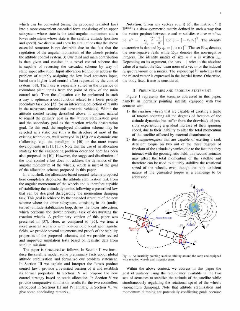
Figure 1 represents the scenario addressed in this paper,namely an inertially pointing satellite equipped with twoactuator sets:
1) the reaction wheels that are capable of exerting a tripleof torques spanning all the degrees of freedom of theattitude dynamics but suffer from the drawback of pos-sibly experiencing a gradual increase of their spinningspeed, due to their inability to alter the total momentumof the satellite affected by external disturbances;
2) the magnetorquers that are capable of exerting a rankdeficient torque on two out of the three degrees offreedom of the attitude dynamics due to the fact that theyinteract with the geomagnetic field; this second actuatormay affect the total momentum of the satellite andtherefore can be used to suitably stabilize the rotationalspeed of the wheels, even though the rank deficientnature of the generated torque is a challenge to beaddressed.
z[B]
y[B]
x[B]
z[I]
x[I]
y[I]
North
South
Magnetorquers
ReactionWheels
z[B]
y[B]
x[B]
Fig. 1. An inertially pointing satellite orbiting around the earth and equippedwith reaction wheels and magnetorquers.
Within the above context, we address in this paper thegoal of suitably using the redundancy available in the twosets of actuators to stabilize the attitude of the satellite whilesimultaneously regulating the rotational speed of the wheels(momentum dumping). Note that attitude stabilization andmomentum dumping are potentially conflicting goals because

3
attitude control requires to speed up (or decelerate) the wheels,which may badly interact with the momentum dumping per-formed by the magnetorquers. From an engineering standpoint,the problem addressed and solved in this paper can be formu-lated as follows.
Problem 1. Given a spacecraft equipped with reaction wheelsand magnetorquers actuators, as represented in Figure 1,design a control strategy for driving the two sets of actuatorsto ensure simultaneously that the body frame is aligned withthe inertial frame (attitude stabilization) and that the angularmomenta of the reaction wheels are stabilized at a givenreference value.
As customary in the case of redundancy of actuators,the engineering problem described in Problem 1 is usuallyaddressed in two steps. First, a suitable attitude stabilizer withrespect to given attitude specifications is obtained. It is basedon an abstract model that does not take the reaction wheelssaturation issue into account. Then, an additional controllayer, implementing this control law for the retained actuationequipment, is designed. We stress that this paper is mainlyconcerned with the second step. Thus, all our derivationsare valid for any stabilizer as long as it satisfies some mildregularity properties. Nevertheless, for illustration purposes,and to show the potential of our scheme to provide globalresults on nonlinear models, we use the attitude controllerproposed in [26].
To suitably address and solve Problem 1, we give in thissection the essential material to formulate it in mathematicalterms. First, the dynamics of the satellite model are describedin Section II-A. Then in Section II-B we recall the globalattitude stabilizer proposed in [26] and prove some additionalproperties that were not given in [26]. Then in Section II-Cwe introduce some assumptions on the satellite orbit thatenable us, together with the other derivations of the section,to mathematically formalize the engineering Problem 1.
Remark 1. We emphasize that the design problem stated inProblem 1 addresses the issue of saturation of the angularspeed of the wheels but should take into account the maximumtorque that can be exerted both by the magnetorquers and bythe reaction wheels actuators. While we do take into accountall these different types of saturations in the simulationscarried out in Section V, we do not take torque saturations intoaccount in our mathematical analysis. Indeed, taking saturationinto account at a design level is a challenging nonlinearcontrol problem that would most likely lead to conservativebounds and possibly sacrifice the small signal behavior. Aviable approach that does not sacrifice local performance isthat of anti-windup design [41], [35], which poses nontrivialtheoretical difficulties when applied to nonlinear saturatedplants (see, e.g., the discussion in the recent paper [21]).Since our allocation-based solution allows for any attitudestabilizer, one may actually take saturation into account inthe attitude stabilization design and then apply our allocation-based desaturation scheme. Clearly, the challenging problemof designing such a stabilizer is beyond the scope of this paper.
◦
A. Attitude equations for an inertially pointing satellite withreaction wheels and magnetorquers
The total angular momentum of the satellite in the body-fixed frame comprises the angular momentum Jω of thecentral body and the angular momentum hw of the reactionwheels:
hT = Jω + hw, (1)
where ω ∈ R3 and J ∈ R3×3 are the rotational speed of thesatellite body-fixed frame with respect to the inertial frame andthe symmetric matrix corresponding to its moment of inertia,respectively. Applying Newton’s theorem in the inertial frame,we get
h[I]T = T [I]
m , (2)
where T [I]m is the torque generated by the magnetorquers and
acting as an external torque on the spacecraft. When expressedin the body-fixed frame, (2) becomes:
hT + ω×hT = Tm, (3)
where the gyroscopic term ω×hT appears due the rotation ofthe body-fixed frame with respect to the inertial frame. Replac-ing hT in (3) by its expression given in (1) and recognizingthat the variation of hw corresponds to the torque τw appliedby the reaction wheels, with straightforward manipulations,we get the dynamic equations in the body-fixed frame:
{Jω + ω×(Jω + hw) = −τw + Tmhw = τw.
(4a)
The attitude of the spacecraft is conveniently describedusing quaternion coordinates q = [ εη ] ∈ S3, where ε ∈ R3
and η ∈ R. By definition, the three-sphere S3 refers to the setof every element q ∈ R4 satisfying the constraint |q| = 1. Foran inertially pointing satellite, the quaternion q characterizesthe instantaneous rotation of the body-fixed frame with respectto the inertial frame. The angular position dynamics is thendescribed by the following well known kinematic differentialequation (see, e.g., [19]):
q = F (ω)q =1
2
[−ω× ω−ωT 0
]q =
1
2
[−ω×ε+ ηω−ωT ε
], (4b)
where F (ω) is clearly a skew-symmetric matrix.The magnetic torque Tm produced by the magnetorquers
originates from the interaction between the local geomagneticfield b and the magnetic momentum1 τm according to thefollowing relationship Tm = −b×τm.Then, the magnetic fieldb is a function of both the location of the spacecraft along itsorbit and its attitude. These two dependencies can be separatedout writing b as R(q)b◦ where R(q) is the rotation matrixexpressing the body-fixed frame with respect to the inertialframe, whose expression clearly depends on the quaternion q,and b◦ is the geomagnetic field expressed in the inertial frame:
Tm = −(R(q)b◦(t)
)×τm. (4c)
1The dynamics of magnetic coils can be neglected as it reduces to a veryfast electrical transient [23].

4
An explicit expression of R(q) can be written as follows, [16]:
R (q) =(η2 − εT ε
)I3 + 2εεT − 2ηε×. (4d)
Under the assumption that the orbital trajectory is perfectlyknown, the time evolution of b◦(t) can be predicted usinga model of the geomagnetic field such as the InternationalGeomagnetic Reference Field (IGRF) which gives access tothe local magnetic field at any point in space [39].
B. Global asymptotic stabilization of the attitude dynamics
In this paper, we will address control design problems formodel (4) derived in the previous section aiming at globalasymptotic stabilization of the attitude dynamics. This problemcan be understood as the problem of designing a feedbackcontroller from (ω, q) capable of globally2 asymptoticallystabilizing a suitable equilibrium for the simpler model givenby (4b) and
Jω + ω×Jω = u+ d (5)
from the control input u. The disturbance input d will be usefullater and should be considered as zero for stability purposes.
Despite its apparent simplicity, this problem involves trickyaspects that have been highlighted, e.g., in [1]. The main con-clusion is that there exists no continuous time-invariant (staticor dynamic) controller that globally asymptotically stabilizes adesired equilibrium attitude. This property is related to the factthat every continuous time-invariant closed-loop vector fieldon SO(3), the set of attitudes of a rigid body, has more than oneclosed-loop equilibrium, and hence, the desired equilibriumcannot be globally attractive [1].
However, as soon as the control law is not continuous ortime-invariant, this obstruction does not hold anymore andmany remarkable solutions to the global attitude stabilizationproblems have been given in the literature (see, e.g. the recentwork [30] and references therein). In this paper, we will usea dynamic (discontinuous) hybrid controller that was recentlyproposed in [26] whose dynamical equation can be written asfollows using the notation in [13], [14]:
xc = 0, (q, ω, xc) ∈ Cx+c = −xc, (q, ω, xc) ∈ Du = −cxcε−Kωω
(6a)
where the flow set C and the jump set D are defined as
C := {(q, ω, xc) ∈ S3 × R3 × {−1, 1} : xcη ≥ −δ}D := {(q, ω, xc) ∈ S3 × R3 × {−1, 1} : xcη ≤ −δ}. (6b)
Note that the scalar controller state xc is constrained tobelong to the set {−1, 1} by the hybrid dynamics. Moreover,the control input u corresponds to a state feedback from (ω, ε)where the sign of the ε gain is toggled by xc. The suggestive
2Note that we actually consider a strict subset of R7, since qT q = 1 holdsfor all times, and thus we shall call this property “asymptotic stability inthe large” rather than “global asymptotic stability” – see [22], however forconsistency with existing results, such as [1], [26], we use “global asymptoticstability” throughout this paper.
result of [26] is that the hybrid controller (6) is able to asymp-totically stabilize the set (attractor) A ⊂ S3 × R3 × {−1, 1}defined as:
A = {q◦}×
000
×{1}
⋃{−q◦}×
000
×{−1} , (7)
which is the union of two points, corresponding to q = q◦and q = −q◦ respectively. Remarkably, due to the well knowndouble coverage nature of quaternion coordinates (see e.g. [5]),these two points correspond to the same element of SO(3), i.e.the same attitude of the satellite. The following lemma statesthe global asymptotic stability result of [26] with an additionallocal exponential stability property which will be useful laterin this paper.
Lemma II.1. For any positive definite matrix Kω = KTω � 0
and scalars c > 0, δ ∈ (0, 1), the closed-loop given by (4b),(5) with d = 0 and (6) is such that the set A in (7) is globallyasymptotically stable (GAS) and locally exponentially stable(LES).
Proof: The proof of GAS is established in [26, Theorem4.2]. To show LES, first recall from [26] that all solutionsto (4b), (5), (6) (with d = 0) are eventually continuous,indeed as noted in [26, top of page 2525], for a suitableLyapunov function V , one has V +−V = −4δ and since V isnon-negative, there cannot be any jump in the neighborhoodof A where V < 4δ. Therefore, we study LES by onlyfocusing on the flow dynamics and continuous-time LESbounds. Moreover, since the two points in A are disjoint,then local analysis amounts to analyzing separately the twopoints (note that since no jumps occur locally, then xc remainsconstant along local solutions). We carry out the analysislooking at the left one in (7), namely x◦ = (q◦, 0, 1). Theother one follows the same steps and is omitted.
Consider now that the motion in S3 can be studied inthe variables ε, ω replacing η by its constrained value η =√
1− εT ε (note also that η is positive around the equilibriumx◦). Then, we can replace (4b) by q = 1
2
[−ω×ε+
√1−εT εω
−ωT ε
]
and the linearized dynamics around the equilibrium x◦ corre-sponds to [ εω ] =
[0 1/2·13
−cJ−1 −J−1Kω
][ εω ] which is exponentially
stable3 for any positive c and positive definite Kω . As aconsequence, from the linear approximation theorem (see,e.g., [20, Thm 4.7]), the equilibrium is LES, namely thereexist positive scalars Υ, λ such that for small enough initialconditions, |(ε(t), ω(t))| ≤ Υ exp(−λt)|(ε(0), ω(0))| for allt ≥ 0. Assume now that ε(0) is small enough so thatη(t) =
√1− ε(t)T ε(t) > 0 for all t ≥ 0. Then, one can
write
|1− η| = (1− η) ≤ (1 + η)(1− η) = 1− η(t)2
= ε(t)T ε(t) ≤ Υ2 exp(−2λt)|(ε(0), ω(0))|2,which gives the local exponential bound also for the variableη and completes the proof of LES.
3This fact is easily proven using the Lyapunov function V = 2cεT ε +ωT Jω which satisfies V = −2ωTKωω, and applying La Salle’s invarianceprinciple.

5
Remark 2. One of the reasons why we adopt the hybridstabilizer of [26] is that the lack of robustness of a non-hybrid stabilizer, together with the so-called unwinding effect(see, [26, §2] for details) is successfully overcome by thehybrid scheme, in light of the results of [14, Ch. 7]. Inparticular, since all the data of the hybrid solutions proposedhere satisfy the basic assumptions of [14] and the attractor(7) is compact, then by applying [14, Lemma 7.20 and Thm7.21], asymptotic stability is robust to small disturbances andsemiglobally practically robust to large ones. In particular,according to the definition in [14, Def. 7.18] all solutions tothe dynamical system generated by perturbing the right handside of the differential equation remain arbitrarily δ-close tothe attractor (7) as long as they start in a ∆-ball around it,where as the size of the disturbance shrinks, one can showthat δ becomes arbitrarily small (practical) and ∆ becomesarbitrarily large (semiglobal). For more details, the reader isreferred to [14]. ◦
Throughout the paper, we will consider the attitude stabi-lizer (6) for the spacecraft dynamics. However, we stress thatthe results presented here are valid for any static or dynamicstabilizer inducing GAS and LES of the attractor A in (7).
C. Mathematical formalization of the design goal
While the stabilization result in Lemma II.1 should beregarded as an important step toward the stabilization ofdynamics (4), it is still not implementable for that dynamics asthe availability of u is an abstraction. Indeed, global asymp-totic stabilization of a suitable attractor for (7) requires to reachthe attitude equilibrium and to dump the momentum hw of thereaction wheels. If using the magnetorquers for this secondarytask, complication arises from the fact that magnetorquers areassociated with tricky time-varying controllability problems.Indeed, at any given instant time, the achievable torque Tmis constrained to a plane because the vector Tm arises fromthe cross product between τm and b and therefore is alwaysorthogonal to b. The fact that the 3×3 matrix b× is structurallysingular originates from this remark. For this reason, thepreliminary feedback
τm =b×
|b|2um (8)
is often used and introduces the new control vector um ∈R3 (see e.g. [24] and references therein) so that the resultingtorque Tm is equal to −b×b×/|b|2um. In such a case, theidentity −b×b×/|b|2 = 13 − bbT /|b|2 allows to interpret Tmas the projection of um on the orthogonal plane to b. Thus, thecontrol action (8) normalizes the magnetic field b and reducesthe control effort by canceling out the useless part of um whichis in the direction of b.
Despite these limitations, strong controllability propertiesstill exist whenever b(t) is time-varying4 and exhibits asufficiently rich behavior in such a way to being capable
4Note that it is also possible to achieve 3-axis stabilization by using onlymagnetorquers, as demonstrated in [24]. However, only poor attitude controlperformance can be expected when using this type of solution because of thevery nature of these singular actuators.
of persistently spanning all of the three-dimensional space.Sufficient properties for the time-varying function t 7→ b(t)to be able to preserve this controllability can be expressed interms of the following matrix:
Π(t) =1
t
∫ t
0
b◦(τ)bT◦ (τ)dτ, (9)
where b◦(t) = b◦(t)/|b◦(t)| is the normalized expression ofthe geomagnetic field in the inertial frame. These propertiesare formalized in the next assumption and suitably commentednext.
Assumption II.1. Given the matrix function t 7→ Π(t) in (9),the following limit exists, is finite and satisfies:
Π∞ = limt→+∞
Π(t), Π∞ ≺ 13. (10)
Moreover, there exists a scalar σ > 0 such that
|M(t)| = |t(Π(t)−Π∞)| ≤ σ, ∀t ≥ 0. (11)
It is interesting to remark that if b◦(τ) is a signal havingfinite power then assumption II.1 is verified [42, Chapter 4].
Remark 3. In our preliminary work [37] we imposed astronger assumption on the magnetic field b◦ because werequired it to be periodic with half of the period T0 of theorbital motion of the spacecraft. In that specific case, the limitin (10) exists and corresponds to Π∞ =
∫ T0/2
0b◦(τ)bT◦ (τ)dτ
and then boundedness of M(t) can be established by noticingthat Π(kT0/2) = Π∞ for each k ∈ Z and using boundednessof b◦. Here we impose milder assumptions on b◦ also inlight of the data reported later in Figure 5, where the actualevolution of b◦ along several orbits is compared to its periodicapproximation.
It is also worthwhile to mention that our Lyapunov construc-tion is inspired by the work of [24], where only the followingassumption is made on the geomagnetic field b◦ (see the firstdisplayed equation in [24, Lemma 1]):
Γ0 = limT→+∞
− 1
T
∫ T
0
b×◦ (τ)b×◦ (τ)dτ, 0 < Γ0 < 13. (12)
Property (12) is weaker than Assumption II.1 and correspondsto only enforcing relation (10), as one can easily check byselecting Γ0 = 13 − Π∞. In [24, Proof of Proposition 1] itis claimed that under the assumption that |b◦(t)| = 1 for allt ≥ 0, (12) is sufficient for the existence of σ > 0 satisfying
(11). Nevertheless, selecting b◦(t) = 12(t+1)
[t+2√
3t2+4t sin(t)√3t2+4t cos(t)
],
it is possible to prove that (12) (equivalently, (10)) holds whilethere exists no σ > 0 satisfying (11). The proof of this fact isgiven in Appendix B.Since we follow the construction of [24,Proposition 1] in our Lyapunov derivations, in light of thisexample, we explicitly enforce (11) in our Assumption II.1.Note that the example above and in Appendix B does notclearly correspond to a plausible physical scenario and arisesfrom a purely mathematical observation. Finally, we shouldemphasize that the result in [24, Prop. 1] has been proven laterin [25] under milder assumptions and with a different prooftechnique. Here we use the Lyapunov-based proof techniqueof [24] that can be effectively employed in our context. ◦

6
Based on Assumption II.1, we can now mathematicallyformalize the engineering problem stated in Problem 1 dealingwith the implementation of the attitude controller presentedin Section II-B to suitably stabilize the spacecraft dynamicspresented in Section II.
Problem 2. Consider the spacecraft described by (4) andsatisfying Assumption II.1. Design a state-feedback controlleracting on the input (τw, τm) which ensures global asymptoticstability of the set A× {hw ∈ R3 : hw = href}, where A isdefined in (7) and href ∈ R3 is any constant setpoint referencefor the angular momentum hw of the reaction wheels.
III. A CLASSICAL APPROACH REVISITED
As a first contribution of this paper, a rigorous mathematicaltreatment of the so-called “cross product control law” isproposed in Sections III-A and III-B before introducing arevisited version of this control law in Section III-C
A. The classical cross-product control law
A classical approach to the solution to Problem 2 is the so-called “cross product control law” well surveyed in [3], [4],[8], [33]. This control law has been used, e.g., in the spacecraftDemeter [28], as described in [29]. The underlying philosophyof this approach is to use the reaction wheels actuator for theattitude stabilization loop, while the momentum of the wheelsis simultaneously regulated by a second control loop acting onthe magnetorquers. This leads to two control loops designedindependently, as illustrated next.
1) The attitude stabilization loop: For attitude stabilization,one can rewrite the first relationship in (4a) as
Jω + ω×Jω = −τw − ω×hw︸ ︷︷ ︸u
+ Tm︸︷︷︸d
. (13)
Note that (13) corresponds to (5) with u = −τw −ω×hw andd = Tm. Then, forgetting for a moment the presence of thedisturbance d (which should however be taken into account ata later stage for stability analysis), the reaction wheels inputτw can be selected by only focusing on the attitude controlgoal using some global asymptotic stabilizer, such as the onediscussed in Section II-B. In particular, with that constructionone can use (6) for u and
τw = −ω×hw − u. (14)
Then, Lemma II.1 implies that attitude stabilization is achievedglobally, with d = 0.
2) The momentum dumping loop: For the task of con-trolling hw, assume that the attitude controller is capable ofconverging to (a small enough neighborhood of) the desiredequilibrium attitude (q, ω) ∈ A given in (7). The equilibrium,u + Tm = 0 gives τw = Tm, for (q, ω) ∈ A. Then,remembering that href is constant, from the second equationin (4a) and from (4c), we get for (q, ω) ∈ A,
˙hw − href = −b×(t)τm. (15)
One can then select the magnetorquers input τm in such away to stabilize the origin of (15) following, for example, the
so-called “cross product control law” of [3], [4], [8], [33],corresponding to
τm = − b×(t)
|b(t)|2kp(hw − href ), (16)
which can be interpreted as the combination of the preliminaryfeedback (8) with a proportional action kp(hw − href ). It canbe shown that this control law globally exponentially stabilizesthe attractor
Ah = {hw ∈ R3 : hw = href} (17)
as stated in the following lemma whose proof, given inAppendix A, follows the same steps as in [24, Prop. 1].
Lemma III.1. If Assumption II.1 holds, then for any scalarkp > 0, the set Ah in (17) is globally exponentially stable forthe closed-loop system (15), (16) with b replaced by b◦.
Remark 4. Following the same philosophy, other control lawshave been proposed in the literature to achieve momentumdumping by focusing on (15). For example, in [23], a periodicLQ controller has been designed relying on numerical methodsto solve the periodic Riccati equation. Moreover, a semi-analytical optimal open-loop solution for only one axis wasproposed in [12]. ◦
B. Quasi-cascade structure of the classical approach
A closer look at the “cross product control law” strategyreveals that the attitude stabilization loop (14) is designedassuming that the second loop is at the equilibrium (namelyhw = href which induces d = Tm = 0 according to (16)and to (4c)). Conversely, the momentum dumping action (16)is designed assuming that the first loop is at the equilibrium(q = q◦ so that b = R(q)b◦ is replaced by b◦ in (15) and(16)). Despite its intuitive interpretation, it seems that formallyshowing desirable stabilization properties of the overall con-troller (6), (14), (16) is not so straightforward. Some directionsare given with respect to this in [3], [4], [6], [9], [15], [23]where a frequency separation argument is required betweenthe two loops cited above, which corresponds to selecting avery aggressive action of the attitude stabilizer (14). This canbe performed, for example, by selecting sufficiently large gainsc and Kω in (6).
One way to tackle the asymptotic stability properties of theequilibrium set A × Ah (see (7) and (17)) for the overalldynamics (4), (6), (14), (16) is to recognize that the inputτw to the reaction wheels does not change the total angularmomentum h
[I]T = RT (q)(Jω+ hw) (this follows easily from
(1) and (2) and is obvious from the fundamental mechanicsviewpoint). Thus, in order to help separating the influence ofeach actuator, it makes sense to use h
[I]T , rather than hw to
represent the momenta of the reaction wheels in the first loop.Indeed, in the set A×Ah, one has h[I]T = RT (±q◦)hw = hw.However, when substituting hw by R(q)h
[I]T −Jω in the “cross
product control law” (16), bearing in mind that kp is a scalar,

7
(Rv)× = Rv×RT for all v ∈ R3 and |b| = |b◦|, one gets
τm = − (R(q)b◦(t))×
|b(t)|2kp(R(q)h
[I]T − Jω − href )
= −R(q)b×◦ (t)
|b◦(t)|2RT (q)kpR(q)(h
[I]T
−RT (q) (Jω +href ))
= −R(q)b×◦ (t)
|b◦(t)|2kp
(h[I]T − href
+RT (q)(
(R(q)− 13)href − Jω︸ ︷︷ ︸ζ(q,ω)
) ).
(18)
b◦(t)
Upper Subsystem
τ [I]m
href
h[I]T
−+
Lower Subsystem
R(q)
RT(q)
Dynamics of
(q, ω)
ζ(q, ω)h[I]T
(q, ω)+
+
++
b×◦ (t)
|b◦(t)|2kp ∫−b×◦ (t)
h[I]T
u HybridController
href
ζ(q, ω)
Fig. 2. The quasi-cascaded structure of the “cross product control law” andthe role of the signal ζ(q, ω).
Equation (18) provides insightful understanding about thequasi-cascaded, or feedback structure of the “cross productcontrol law” which, based on (18) can be remapped in theinertial coordinate frame to get
τ [I]m = − b×◦ (t)
|b◦(t)|2kp
(h[I]T − href +RT (q)ζ(q, ω)
). (19)
This is clarified in the block diagram of Figure 2 wherethe presence of the signal ζ(q, ω) creates an undesirabledependence of h[I]T on the attitude parameters (q, ω). Eventhough the literature contains reference to frequency separation(or two time scale results when speaking in nonlinear terms),it is unclear how to apply those results to the scheme ofFigure 2, where the time-varying input b◦(t) makes it hardto say that the upper subsystem is slower than the lower one.Conversely, a possible way to establish asymptotic stability ofthe attractor is via the input-to-state (ISS) small gain approach[17] where one could claim that increasing the gain of theattitude stabilizer in the lower subsystem allows to reduceenough the ISS gain from h
[I]T to RT (q)ζ in the block diagram.
Then, one could characterize the “cross product control law”solution as some sort of high-gain feedback solution leadingto global asymptotic stabilization of the set A × Ah definedin (7) and (17) via small gain results.
C. A revisited cross-product control law
While the “cross product control law” approach of theprevious section has been long used in experimentation andperforms desirably when a high-gain attitude stabilization isadopted, the natural question that arises in light of (18) iswhether the signal ζ(q, ω) is really necessary. The answeris no, if one recalls that the stabilizer (16) was designed by
focusing on the case (q, ω) ∈ A and that in this set one hasζ(q, ω) = 0. Consequently, this signal ζ can be freely insertedinto (16) to obtain the “revisited cross-product control law”:
τm = − b×(t)
|b(t)|2kp(hw − href − ζ(q, ω)), (20a)
which can be used as an alternative to stabilizer (16). Theadvantage of using the revisited law (20a) in place of theclassical one (16) is best appreciated by rewriting (20a) asfollows, by using the identities in (18):
τ [I]m = − b×◦ (t)
|b◦(t)|2kp(h
[I]T − href ). (20b)
0 0.2 0.4 0.6 0.80
0.01
0.02
0.03
0.04
0.05
0.06
Non-aggressive controller
Position on orbit (%)0 0.002 0.004 0.006 0.008 0.01 0.012
0
1
2
3
4
5
6
7x 10
−3
Position on orbit (%)
Aggressive controller
revisitedclassical
|ω| × 102
1− |η|
1− |η|
|ω| × 104
Fig. 3. Comparison in Remark 5 between the classical (dashed) and revisited(solid) “cross-produce control laws” when using an aggressive attitude con-trollers (left-hand side plot) and a non-aggressive one (right-hand side plot).
Remark 5. From an engineering viewpoint, the revisited con-trol strategy given by (6), (14) and (20) is not much differentfrom the classical “cross-product control law” (6), (14), (16)whenever the attitude stabilizer is aggressive enough so thatthe standing assumptions behind this historical approach arerespected. However, significant differences are witnessed whenusing non aggressive actions in the attitude controller and thismainly because while the revisited solution keeps performingdesirably, the classical solution exhibits very large overshootsand even diverging responses. This can be motivated by thefact that the interaction between the momentum dumper (uppersubsystem) and the attitude stabilizer (lower subsystem) inFigure 2 does not anymore satisfy a small gain condition andasymptotic stability is lost.
Figure 3 illustrates this fact by comparatively showing theresponses of the two closed-loops starting from the initialconditions w0 = 0, q0 = [0.10, 0.05, 0.02, 0.99]T , hw0 =[0.09, 0.072, 0.078]T , xc0 = 1. For illustration purposes, thesimulations of Figure 3 have been carried out without imposing

8
any saturation limits on τw and τm, so that the differenceamong the two dynamic solutions can be best appreciated.Simulations incorporating these saturations are carried out inSection V. In the figure, the dashed lines correspond to theresponse obtained from the classical solution (6), (14), (16)and the solid lines correspond to the revisited law (6), (14) and(20). With these two controllers, two cases are analyzed: theleft-hand side plot shows the responses obtained when usingan aggressive attitude controller, corresponding to Kw = 5 ·13
and c = 0.5 while the right plot corresponds to the lessaggressive gains Kw = 0.07 · 13, c = 10−4. In both cases,we consider δ = 0.5 and kp = 0.01. We illustrate the closed-loop responses by showing the (rescaled) norm of the angularspeed and the scalar value 1−|η| which is zero in the attractor.Similar comparison results are experienced when looking atall the components of the state (q, ω, xc, hw). Note that theresponses of the two closed-loops are essentially the same inthe case when the classical solution performs desirably, butthe revisited solution preserves asymptotic convergence to theattractor, with the less aggressive attitude stabilizer. ◦
One advantage arising from replacing (16) by (20) is thatthe feedback interconnection of Figure 2 becomes a cascadedinterconnection (the dashed arrow disappears) and one canthen use results on stability of cascaded nonlinear systemsto establish global asymptotic stability of the set A × Ahdefined in (7) and (17). In particular, for the cascaded systemof Figure 2, the upper subsystem regulates the total angularmomentum using the magnetorquers and is completely inde-pendent from the satellite attitude and the lower subsystemregulates the attitude dynamics using the reaction wheels andis disturbed by the upper subsystem through the action ofd = Tm = −R(q)b◦(t)×τ
[I]m . More specifically, the overall
closed-loop corresponds to the “revisited cross-product controllaw” (6), (20) together with
h[I]T = −b◦(t)×τ [I]m (21a){
(4b)Jω + ω×Jω = u+R(q)h
[I]T .
(21b)
Using the result established by Lemma III.1, which canbe rewritten in the same form when looking at the feedback(21a), (20b), one gets global exponential stability of theupper subsystem. Then, Global Asymptotic Stability can bederived from properties of cascaded interconnections of hybridsystems (recall that the attitude controller is hybrid). The resultis formalized in the following theorem.
Theorem III.1. Under Assumption II.1, given any set of gainskp > 0, Kω = KT
ω � 0, c > 0 and δ ∈ (0, 1), considerthe closed-loop system between plant (4) and controller (6),(14), (20a) with state space variables x = (q, ω, xc, hw). Then,the set Ae = A × Ah as defined in (7) and (17) is locallyasymptotically stable.
Moreover, if the hybrid closed-loop system (4b), (5), (6) isISS from the input d (in the sense of [2]), then the set Aeis globally asymptotically stable, namely the control schemesolved the formalization in Problem 2 of the engineeringProblem 1.
Proof: First let us represent the closed-loop with thecoordinates x = (q, ω, xc, h
[I]T ) and note that, from (1) and
h[I]T = RT (q)hT , we have x ∈ Ae if and only if x ∈ Ae. Then,
we can prove the theorem by studying asymptotic stability ofAe for the transformed dynamics (6), (20b) (21) which is incascaded form.
For this cascade, using Lemma III.1 rewritten by replacinghw by h
[I]T , the set Ah is globally exponentially stable for
the upper subsystem, corresponding to (21a), (20b). Moreover,the lower subsystem with zero input, corresponding to (6),(21b) with h[I]T = 0, coincides with (4b), (5), (6) with d = 0and therefore guarantees global asymptotic stability (and localexponential stability) of the set A from Lemma II.1. Then, wecan apply [13, Corollary 19] and the follow-up results aboutthe cascades [13, eqn. (23)] to prove local asymptotic stabilityof the cascade5. Moreover, if the lower subsystem is input-to-state stable with respect to d in the sense of [2], then allsolutions are bounded for any initial condition. Then, the resultfollows once again from the results on cascaded system statedfor [13, eqn. (23)].
IV. USING STATIC ALLOCATION TO INVERT THE CASCADE
The solution to Problem 2 presented in the previous sectioncan lead to satisfactory closed-loop responses, however itsuffers from three main drawbacks.
1) Due to the cascaded structure of Figure 2, the attitudecontrol loop is undesirably disturbed by the momen-tum dumping system. Since attitude control is moreimportant than momentum dumping, it would be moredesirable if the converse relation was in place.
2) Global asymptotic stability is only established by Theo-rem III.1 under an ISS assumption on the attitude controlsystem, which is not easy to guarantee in general. Itwould be more desirable to have a solution to Problem 2which is effective without requiring anything more thanGAS and LES of the attractor for the attitude controlsystem.
3) The solution should be implemented using (20a) that,through ζ(q, ω), requires exact knowledge of the inertiaJ and may result in lack of robustness if J is uncertain.
The limitations above can be overcome by following analternative paradigm for the design of the stabilizing law,which arises from the intuition of reversing the cascadedstructure of Figure 2. This inversion of the cascade wouldresult in the fact that the attitude stabilization would not bedisturbed at all by the momentum dumping. In order to givepriority to the attitude control goal, we revisit equation (13)and perform a different partition of the terms at the right handside in such a way that the disturbance d of the equivalentformulation (5) is zero:
Jω + ω×Jω = −τw − ω×hw + Tm︸ ︷︷ ︸u
. (22)
5Note that in [26] forward completeness of all maximal solution is provenso all pre-asymptotic stability results are equivalent to asymptotic stabilityresults.

9
Then, the attitude dynamics (4b), (22) corresponds to (4b), (5)with u = −τw − ω×hw + Tm and d = 0. Following the samesteps as in the previous section, the reaction wheels input τwcan then be selected by only focusing on the attitude controlgoal using some global asymptotic stabilizer, such as the onediscussed in Section II-B. In particular, with that construction,one can use (6) and select
τw = −ω×hw + Tm − u= −ω×hw − (R(q)b◦(t))×τm − u
(23)
(where we used (22) and (4c)). Then Lemma II.1 impliesthat attitude stabilization is achieved globally, regardless ofthe torque Tm generated by the magentorquers.
As a next step, we can now focus on the momenta of thereaction wheels, which are indeed affected by the magnetor-quers indirectly from the input selection (23). In particular,using the second equation in (4a), selection (23) and the factthat href is constant, we get
˙hw − href = −ω×hw − u− (R(q)b◦(t))
×τm, (24a)
orh[I]w = −RT (q)u− b×◦ (t)τ [I]m , (24b)
which reveals that the momentum of the reaction wheels isindeed affected by the attitude variables due to the presenceof u at the right hand side. Remarking that if (q, ω) ∈ Athen (24a) reduces to (15), it appears natural to select themagnetorquers input τm in such a way to exploit the usefulstabilization result of Lemma III.1, namely
τm = − (R(q)b◦(t))×
|b◦(t)|2kp(hw − href ), (25a)
or
τ [I]m = − b×◦ (t)
|b◦(t)|2kp(h
[I]w −RT (q)href ), (25b)
where kp is a positive scalar gain.
Dynamics of
(q, ω)(q, ω)
Upper Subsystem
u
Lower Subsystem
b◦(t)
href
h[I]w
−τ [I]m
u u[I]
−−
∫
+b×◦ (t) − b×◦ (t)
|b◦(t)|2kp RT (q)
RT (q)
Hybrid
controller
Fig. 4. Cascaded structure of the static allocation scheme.
The structure of the control loop is illustrated in Figure 4in order to make a thorough comparison with the structurerepresented in Figure 2. The corresponding equations of theclosed-loop system are composed of the control laws (6), (25b)and the upper subsystem
{(4b)Jω + ω×Jω = u,
(26)
which affects the lower subsystem (24b) (25b). This cascadedstructure should be compared to (6), (20) and (21). In particu-lar, comparing Figure 4 to Figure 2, it is obvious that we have
exchanged the order of the attitude and momentum dumpingsubcomponents. As mentioned above, an advantage arisingfrom the new cascaded structure of Figure 4 is that the attitudecontrol goal becomes the primary goal and is associated withtransient responses that are not disturbed by the momentumdumping controller. Therefore, even though the limit set of theclosed-loop trajectories is the same under both controllers, thesolution of this section has no impact at all on the transient ofthe attitude dynamics. This feature is well illustrated by thesimulation examples of Section V.
Theorem IV.1. Under Assumption II.1, given any set of gainskp > 0, Kω = KT
ω � 0, c > 0 and δ ∈ (0, 1), considerthe closed-loop system between plant (4) and controller (6),(23), (25a) with state space variables x = (q, ω, xc, hw). Thenthe set Ae = A × Ah as defined in (7) and (17) is globallyasymptotically stable, namely the control scheme solves theformalization in Problem 2 of the engineering Problem 1.
Proof: The proof uses the results for asymptotic stabilityof nonlinear hybrid cascaded interconnections that have beenrecalled in the proof of Theorem III.1 (namely [13, Corollary19] and the follow-up results about the cascades [13, eqn.(23)]). In particular, generalizing to the hybrid case the classi-cal continuous-time result of [34], global asymptotic stabilityof the cascaded interconnection can be established by usingGAS and LES of the upper subsystem (which holds due toLemma II.1), 0-GAS of the lower subsystem (namely GASwith zero input) and global boundedness (UGB) of trajectories.These three items are proven below.
0-GES of the lower subsystem. As already said, the zeroinput equation of the lower subsystem corresponds to (15),(25a) (where it is recalled that b(t) = R(q)b◦(t)). Thus,Lemma III.1 can be directly applied to prove that Ah isglobally exponentially stable for the lower subsystem with zeroinput.
Global Boundedness. By global boundedness (GB) of theclosed-loop (4), (6), (23), (25a), we mean that for each r > 0,there exists Ψ(r) > 0 such that 6 for each initial conditionx0 = (ω0, q0, xc0, hw0) satisfying |x0|A×Ah
≤ r, one hasthat all solutions x satisfy |x(t, j)|A×Ah
≤ Ψ(r) for all(t, j) ∈ dom(x). To show this, first note that GAS of theupper subsystem implies GB of the (ω, q, xc) substate. Asfor the state hw, consider the function H = |hw|2/2 wherehw = hw − href and note that hw does not change acrossjumps, while along flows, from (24a) we get:
H = hTw(−ω×(hw + href )− b×(t)τm − u)
= −hTw(u+ ω×href
)+ kph
Tw
b×(t)b×(t)
|b(t)|2hw,
indeed hTwω×hw = −hTwh×wω = 0. Then defining
ρ(t) := |u| + |ω×href | and remarking that −b×(t)b×(t) =(b×(t))T b×(t) � 0,∀t, H can be bounded as follows:
H ≤ |hw| ρ(t) ≤ (1 + |hw|2)ρ(t) = (1 + 2H)ρ(t).
6As customary, given a set S and a vector w, we denote the distance of wfrom S as |w|S := inf
z∈S|w − z|.

10
From GAS and LES of the (ω, q) dynamics, for each r > 0there exist positive Kr, λr such that ρ(t) ≤ Kr exp(−λrt).Then, from Gronwall-Bellman’s inequality [20, Lemma A.1],since ρ(t) is integrable, we have that H = |hw|2/2 is globallybounded.
Let us now summarize the important advantages of usingthe new allocation-based scheme of this section as comparedto the two approaches presented in Section III:
1) Unmodified transient of the attitude dynamics. Bearingin mind that the scheme works for any attitude stabilizerinducing GAS and LES, the transient response inducedby the preferred attitude stabilizer is preserved by theallocation-based scheme because the controlled attitudedynamics is now the upper (undisturbed) block of thecascaded structure. Note that an interesting propertyinduced by this feature is that the attitude stabilizationis independent of b(t) (or b◦(t)) which leads to moredesirable robustness properties of the closed loop due toan intrinsic decoupling property.
2) Only GAS and LES of the attitude stabilizer is required.As formally stated in the previous Theorem IV.1, globalasymptotic stability of the attractor Ae holds under themild requirement that the attitude stabilizer induce GASand LES. This shows clear advantages as comparedto: 1) the classical approach, for which instability canbe observed for an non-aggressive attitude stabilizerinducing GAS and LES, and 2) its revisited version,which requires an extra ISS property from the attitudestabilizer, as stated in Theorem III.1. Note also that GASof the attractor Ae implies uniform global convergenceof the speed of the reaction wheels to the desiredreference href . Finally, it is also worthwhile mentioningthat the stability properties guaranteed for the allocation-based scheme hold globally. In other terms, this meansthat the proposed strategy can be suitably employedwhen dealing with either large or small depointings.To our best knowledge, nothing can be said about theclassical scheme with respect to this.
3) Dealing with saturations. Regarding saturation of in-put torques and reaction wheels speed, the allocation-based scheme is preferable as compared to the classicalone for two reasons. First, a formal proof of stabilitydemonstrates that, with the allocation-based scheme,hw converges to the arbitrary set point href , which,when suitably defined, helps keeping hw away from thesaturation bounds and from zero velocity which inducesundesirable stiction effect. Secondly, global stabilitywith the new scheme is guaranteed regardless of theaggressiveness of the attitude stabilizer. This allowsimplementing low-gain attitude controllers, less inclinedto induce saturation of hw, τw and τm. Simulation resultsproposed in the next section confirm that this propertydoes not hold for the classical scheme.
4) Robustness with respect to model parameters. In the casewhere b(t) is measured on board, the new control law isindependent of the model parameters. This was not thecase in the revisited version of the classical approach,
where J is required7. This may be easily shown bycomparing (25a) with (20a) where, in this last case, thedependence upon the inertia matrix J comes throughthe term ζ(q, ω). This remark is an argument in favorof the robustness of the proposed allocation scheme asexplained, e.g., in [38].
V. SIMULATION RESULTS
To suitably illustrate the control schemes proposed inthis paper, we provide in this section a range of numericalsimulations. All the simulation tests are carried out usingthe physical parameters parameters of the satellite Demeter[28] designed and produced by CNES, the French spaceagency. This spacecraft is the first microsatellite in the Myriadeseries, a new concept of modular satellite weighing less than200 kg, flying at an altitude of 710 km, and developed toprovide an affordable access to space. Launched on June 29,2004, the Demeter mission has now come to its end andthe satellite was terminated on December 9, 2010. Like mostlow orbit satellites, Demeter is equipped with reaction wheelsand magnetorquers. A star tracker is used to measured itsattitude. All numerical data and specifications were providedby CNES [28] and correspond to the ones used for the realdesign of the control system implemented on board duringthe flight of Demeter. For simplicity of the exposition, theDemeter example is used here for an inertial pointing mission(as graphically shown in Figure 1), while the real missionneeded geocentric pointing. The inertia matrix is given by
J =
39.30 −3.65 −0.37−3.65 27.15 −1.45−0.37 −1.45 46.54
(kg.m2).
The nominal angular momentum of each reaction wheel ischosen to be 0.06 N.m.s, so that the constant vector href isgiven by 0.06 · [1, 1, 1]T . The actuators need to comply withthe following constraints:
|hiw| ≤ 2hiref = 0.12 N.m.s, |τ iw| ≤ 0.005 N.m,
|τ im| ≤ 12 A.m2, ∀ i = 1, 2, 3.
The circular orbit considered for the satellite is characterizedby an altitude of 660 km, an inclination of 98.23◦ and a localtime of the ascending node of 22h15. From these parameters,the geomagnetic field b◦(t) is evaluated using the InternationalGeomagnetic Reference Field (IGRF) model. Figure 5 showsthe chronograph of b◦ over a time range of 60 orbits, togetherwith its periodic approximation. It is emphasized that in ourpreliminary work [37] we investigated the stability propertiesof our schemes under a periodicity assumption for b◦. Figure 5well illustrates the relevance of the extension, carried out inthis paper, to non-periodic instances of b◦. In Figure 5 as wellas in all the other figures reported in this section we use thefollowing color codes: the x component is shown in blue, they component is shown in red and the z component is shownin green.
7It should be however stated that the original classical “cross-product”control law does not require the knowledge of J .

11
0 10 20 30 40 50 60 70 80 90 100−50
−40
−30
−20
−10
0
10
20
30
40
50b ◦(t)
(µT)
Position on orbit (%)
Fig. 5. Chronograph of b◦ together with its periodic approximation (thickcyan line) over 60 orbits.
Several stabilization problems with non-nominal initial an-gular momentum of the wheels have been simulated using thecontrol laws presented in this paper, namely:
1) the classical approach (dash-dotted lines in our figures);2) its revisited version (dashed lines);3) the allocation-based strategy (solid lines).
For all our simulations, unless differently specified, the initialconditions are selected as hw0 = [0.09, 0.05, 0.04]T , ω0 =0, ε0 = [0.10, 0.05, 0.02]T and η0 =
√1− εT0 ε0.
Regarding the parameter kp inducing momentum dumping,keeping in mind that it should be strictly positive, we ran sev-eral numerical simulations of the closed-loop (15) with (16).The resulting choice was kp = 5 ·10−3. Remarkably, choosinglarger or smaller values leads to deteriorated responses, whichreveals somewhat interesting trends of the linear time-varyingstabilizing law (16).
1) Aggressive attitude stabilizer: As a first test, the parame-ters of the hybrid attitude stabilizer u defined by (6) are chosento make this control law aggressive: We assign Kω = 5·13 andc = 0.5. Additionally, xc0 = 1 and δ = 0.5. The simulationresults are displayed in Figure 6 and Figure 7. While allclosed-loop systems eventually converge to the desired attitudeequilibrium for all control strategies, it can be seen that all theactuators signals, namely hw, τw and τm, hit the saturationlimits (dotted horizontal lines). This is the main drawback ofselecting an aggressive attitude stabilizer. Note that using anaggressive attitude controller induces comparable responses onall of the three proposed schemes. We will point out that thisis not the case when studying the responses in the presenceof disturbances, as illustrated at the end of the section.
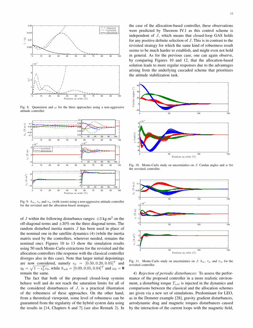
2) Non-aggressive attitude stabilizer: In a subsequent sim-ulation test, to prevent saturation, the attitude stabilizer param-eters are redefined in order to obtain an attitude controller thatis less demanding for the actuators. In particular, we choosethe smaller values c = 10−4 and Kω = 0.07 · 13, while δand xc0 remain unchanged. The simulation results startingfrom the same initial conditions are displayed in Figures 8and 9. From Figure 8, it appears that the classical (dash-dotted)controller leads to instability as one would expect in light ofthe discussions already provided in Remark 5. Instead, theother control strategies ensure convergence to the equilibrium(as predicted by Theorems IV.1 and III.1) without reachingthe actuators limits. Finally, one can observe that the time
0 1 2 3 4 5 6 7 8 9 100
1
2
3
4
5
6
7x 10
−3
1−|η|
classicalrevisitedallocation
0 1 2 3 4 5 6 7 8 9 100
0.5
1
1.5
2
2.5
3x 10
−5
|ω|
Position on orbit (%)
Fig. 6. Quaternion and ω for the three approaches using an aggressive attitudecontroller.
0 1 2 3 4 5 6 7 8 9 10
−0.1
−0.05
0
0.05
0.1
hw(N
.m.s)
0 1 2 3 4 5 6 7 8 9 10
−5
0
5
x 10−3
τ w(N
.m)
classicalrevisitedallocation
0 1 2 3 4 5 6 7 8 9 10
−10
0
10
τ m(A
.m2)
Position on orbit (%)
Fig. 7. hw , τw and τm for the three approaches using an aggressive attitudecontroller.
evolution of (ω, q) is more regular with the allocation schemethan it is with the revisited approach. This result is expectedas it originates from the hierarchical relationship between thetwo stabilization tasks, represented in Figure 4, where theattitude control loop is independent of the momentum dumpingtask so that the allocation control law intrinsically preventsthe transient of the reaction wheels desaturation loop fromintroducing disturbances on the attitude transient.
3) Influence of the uncertainties on the model parameters:Based on the observations already mentioned in Remark 2,the asymptotic stability properties established in this paper arerobust to disturbances of the plant dynamics. In light of thisfact, using the same non-aggressive attitude stabilizer, a set ofMonte-Carlo simulations has been performed to evaluate thesensitivity of each control scheme to variations of J . In par-ticular, following the benchmark definition proposed in [28],the Monte-Carlo extractions for the randomized analysis havebeen carried out using a uniform distribution of the parameters
12
0 10 20 30 40 50 60 70 80 90 1000
0.005
0.01
0.015
0.021−|η|
classicalrevisitedallocation
0 10 20 30 40 50 60 70 80 90 1000
1
2
3
4x 10
−7
|ω|
Position on orbit (%)
Fig. 8. Quaternion and ω for the three approaches using a non-aggressiveattitude controller.
0 10 20 30 40 50 60 70 80 90 100
−0.1
−0.05
0
0.05
0.1
hw(N
.m.s)
0 20 40 60 80 1000.02
0.04
0.06
0.08
0.1
0 10 20 30 40 50 60 70 80 90 100
−5
0
5
x 10−3
τ w(N
.m)
revisitedallocation
0 20 40 60 80 100
−1
0
1x 10
−4
0 10 20 30 40 50 60 70 80 90 100
−10
0
10
τ m(A
.m2)
Position on orbit (%)
0 20 40 60 80 100−8
−6
−4
−2
0
2
Fig. 9. hw , τw and τm (with zoom) using a non-aggressive attitude controllerfor the revisited and the allocation-based strategies.
of J within the following disturbance ranges: ±3 kg.m2 on theoff-diagonal terms and ±30% on the three diagonal terms. Therandom disturbed inertia matrix J has been used in place ofthe nominal one in the satellite dynamics (4) (while the inertiamatrix used by the controllers, wherever needed, remains thenominal one). Figures 10 to 13 show the simulation resultsusing 50 such Monte-Carlo extractions for the revisited and theallocation controllers (the response with the classical controllerdiverges also in this case). Note that larger initial depointingsare now considered, namely ε0 = [0.50, 0.20, 0.05]T andη0 =
√1− εT0 ε0, while hw0 = [0.09, 0.05, 0.04]T and ω0 = 0
remain the same.The fact that both of the proposed closed-loop systems
behave well and do not reach the saturation limits for all ofthe considered disturbances of J , is a practical illustrationof the robustness of these approaches. On the other hand,from a theoretical viewpoint, some level of robustness can beguaranteed from the regularity of the hybrid system data usingthe results in [14, Chapters 6 and 7] (see also Remark 2). In
the case of the allocation-based controller, these observationswere predicted by Theorem IV.1 as this control scheme isindependent of J , which means that closed-loop GAS holdsfor any positive definite selection of J . This is in contrast to therevisited strategy for which the same kind of robustness resultseems to be much harder to establish, and might even not holdin general. As for the previous case, one can again observe,by comparing Figures 10 and 12, that the allocation-basedsolution leads to more regular responses due to the advantagesarising from the underlying cascaded scheme that prioritizesthe attitude stabilization task.
0 50 100 150
−20
0
20
40
60
Cardan
angles
(◦)
0 50 100 150
−8
−6
−4
−2
0
2
4
6x 10
−4
ω(rad
/s)
Position on orbit (%)
Fig. 10. Monte-Carlo study on uncertainties on J : Cardan angles and w forthe revisited controller.
0 50 100 1500
0.05
0.1
hw(N
.m.s)
0 50 100 150−2
−1
0
1
2x 10
−4
τw(N
.m)
0 50 100 150
−10
−5
0
5
τm(A
.m2)
Position on orbit (%)
Fig. 11. Monte-Carlo study on uncertainties on J : hw , τw and τm for therevisited controller.
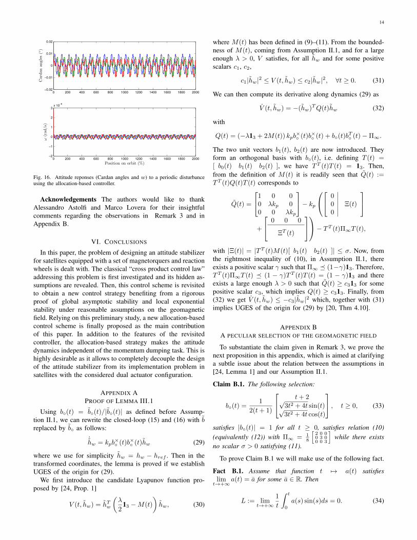
4) Rejection of periodic disturbances: To assess the perfor-mance of the proposed controller in a more realistic environ-ment, a disturbing torque Text is injected in the dynamics andcomparisons between the classical and the allocation schemesare given via a new set of simulations. Predominant for LEO,as in the Demeter example [28], gravity gradient disturbances,aerodynamic drag and magnetic torques disturbances causedby the interaction of the current loops with the magnetic field,

13
0 50 100 150
−20
0
20
40
60
Cardan
angles
(◦)
0 50 100 150
−8
−6
−4
−2
0
2
4
6x 10
−4
ω(rad
/s)
Position on orbit (%)
Fig. 12. Monte-Carlo study on uncertainties on J : Cardan angles and w forthe allocation-based controller.
0 50 100 1500
0.05
0.1
hw(N
.m.s)
0 50 100 150−2
−1
0
1
2x 10
−4
τw(N
.m)
0 50 100 150
−10
−5
0
5
τm(A
.m2)
Position on orbit (%)
Fig. 13. Monte-Carlo study on uncertainties on J : hw , τw and τm for theallocation-based controller.
can be modeled in the inertial frame by two periodic signalsT1 and T2, whose period is one and two times the orbitalfrequency ω0 added to a secular term T0 (see [7], [36]):
T[I]ext(t) =T0x + T1x sin(ω0t+ ϕ1x) + T2x sin(2ω0t+ ϕ2x)T0y + T1y sin(ω0t+ ϕ1y) + T2y sin(2ω0t+ ϕ2y)T0z + T1z sin(ω0t+ ϕ1z) + T2z sin(2ω0t+ ϕ2z)
(27)
The dynamic equation (4a) is then modified accordingly andcorresponds to:
Jω + ω×(Jω + hw) = −τw + Tm +R(q)T[I]ext(t). (28)
Simulations have been performed over 20 orbits usingthe aggressive attitude stabilizer previously introduced andare reported in Figures 15 and 16. For these simulations,according to [7], [36], the numerical parameteres in (27) havebeen selected as follows: T0x = T0y = T0z = 1.0 · 10−7
(N.m), T1x = T1y = T1z = 2.1 · 10−5 (N.m), T2x =T2y = T2z = 2.1 · 10−5 (N.m), ϕT1x = −ϕT2x = π/4,
0 0.1 0.2 0.3 0.4 0.5 0.6 0.7 0.8 0.9 1−5
0
5x 10
−5
Position on orbit (%)
T[I]
ext(t)(N
.m)
Fig. 14. The periodic disturbance T [I]ext used for the simulations of Figures 15
and 16.
ϕT1y = −ϕT2y = −π/4, ϕT1z = 0 and ϕT2z = π/2. Thiscorresponds to the periodic trace for the overall disturbanceT
[I]ext represented in Figure 14.To remain coincise, only the attitude responses variables
are displayed in Figures 15 and 16. Indeed, the two controlschemes lead to very similar behavior of the actuators signals(namely hw, τw and τm) that exhibit an oscillatory behaviorthat remains well within the saturation limits. The mostrelevant insight coming from this last set of simulation isrevealed by a comparative evaluation of the attitude variablesof Figures 15 and 16. Indeed, the advantages arising fromthe cascaded structure of the allocation-based solution (seeFigure 4), where the allocation closed-loop is completelyindependent of b◦, can be well appreciated in Figure 16,where the attitude is only affected by the periodic externaldisturbance torque T [I]
ext and the attitude variables converge to aperiodic steady-state. Conversely, for the structure in Figure 2of the classical strategy, the attitude variables are affected byboth T
[I]ext and the non-periodic term b◦ (see Figure 5). As a
result, the behavior of the attitude variables is non-periodic.Finally, it should be noted that from the two block diagramsof Figures 4 and 2, the attitude of the classical controlleris disturbed by its feedback interaction with the momentumdumping dynamics. This fact explains the larger irregularoscillations that can be appreciated by comparing Figures 15and 16.
0 200 400 600 800 1000 1200 1400 1600 1800 2000−0.02
−0.01
0
0.01
0.02
Cardan
angles
(◦)
0 200 400 600 800 1000 1200 1400 1600 1800 2000−2
−1
0
1
2
3x 10
−6
ω(rad
/s)
Position on orbit (%)
Fig. 15. Attitude reponses (Cardan angles and w) to a periodic disturbanceusing the classical controller.
14
0 200 400 600 800 1000 1200 1400 1600 1800 2000−0.02
−0.01
0
0.01
0.02Cardan
angles
(◦)
0 200 400 600 800 1000 1200 1400 1600 1800 2000−2
−1
0
1
2
3x 10
−6
ω(rad
/s)
Position on orbit (%)
Fig. 16. Attitude reponses (Cardan angles and w) to a periodic disturbanceusing the allocation-based controller.
Acknowledgements The authors would like to thankAlessandro Astolfi and Marco Lovera for their insightfulcomments regarding the observations in Remark 3 and inAppendix B.
VI. CONCLUSIONS
In this paper, the problem of designing an attitude stabilizerfor satellites equipped with a set of magnetorquers and reactionwheels is dealt with. The classical “cross product control law”addressing this problem is first investigated and its hidden as-sumptions are revealed. Then, this control scheme is revisitedto obtain a new control strategy benefiting from a rigorousproof of global asymptotic stability and local exponentialstability under reasonable assumptions on the geomagneticfield. Relying on this preliminary study, a new allocation-basedcontrol scheme is finally proposed as the main contributionof this paper. In addition to the features of the revisitedcontroller, the allocation-based strategy makes the attitudedynamics independent of the momentum dumping task. This ishighly desirable as it allows to completely decouple the designof the attitude stabilizer from its implementation problem insatellites with the considered dual actuator configuration.
APPENDIX APROOF OF LEMMA III.1
Using b◦(t) = b◦(t)/|b◦(t)| as defined before Assump-tion II.1, we can rewrite the closed-loop (15) and (16) with breplaced by b◦ as follows:
˙hw = kpb
×◦ (t)b×◦ (t)hw (29)
where we use for simplicity hw = hw − href . Then in thetransformed coordinates, the lemma is proved if we establishUGES of the origin for (29).
We first introduce the candidate Lyapunov function pro-posed by [24, Prop. 1]
V (t, hw) = hTw
(λ
213 −M(t)
)hw, (30)
where M(t) has been defined in (9)–(11). From the bounded-ness of M(t), coming from Assumption II.1, and for a largeenough λ > 0, V satisfies, for all hw and for some positivescalars c1, c2,
c1|hw|2 ≤ V (t, hw) ≤ c2|hw|2, ∀t ≥ 0. (31)
We can then compute its derivative along dynamics (29) as
V (t, hw) = −(hw)TQ(t)hw (32)
with
Q(t) = (−λ13 + 2M(t)) kpb×◦ (t)b×◦ (t) + b◦(t)b
T◦ (t)−Π∞.
The two unit vectors b1(t), b2(t) are now introduced. Theyform an orthogonal basis with b◦(t), i.e. defining T (t) =[ b0(t) b1(t) b2(t) ], we have TT (t)T (t) = 13. Then,from the definition of M(t) it is readily seen that Q(t) :=TT (t)Q(t)T (t) corresponds to
Q(t) =
1 0 00 λkp 00 0 λkp
− kp
00 Ξ(t)0
+
0 0 0
ΞT (t)
− TT (t)Π∞T (t),
with |Ξ(t)| = |TT (t)M(t)[ b1(t) b2(t) ]| ≤ σ. Now, fromthe rightmost inequality of (10), in Assumption II.1, thereexists a positive scalar γ such that Π∞ � (1−γ)13. Therefore,TT (t)Π∞T (t) � (1 − γ)TT (t)T (t) = (1 − γ)13 and thereexists a large enough λ > 0 such that Q(t) ≥ c313 for somepositive scalar c3, which implies Q(t) ≥ c313. Finally, from(32) we get V (t, hw) ≤ −c3|hw|2 which, together with (31)implies UGES of the origin for (29) by [20, Thm 4.10].
APPENDIX BA PECULIAR SELECTION OF THE GEOMAGNETIC FIELD
To substantiate the claim given in Remark 3, we prove thenext proposition in this appendix, which is aimed at clarifyinga subtle issue about the relation between the assumptions in[24, Lemma 1] and our Assumption II.1.
Claim B.1. The following selection:
b◦(t) =1
2(t+ 1)
t+ 2√3t2 + 4t sin(t)√3t2 + 4t cos(t)
, t ≥ 0, (33)
satisfies |b◦(t)| = 1 for all t ≥ 0, satisfies relation (10)(equivalently (12)) with Π∞ = 1
8
[2 0 00 3 00 0 3
]while there exists
no scalar σ > 0 satisfying (11).
To prove Claim B.1 we will make use of the following fact.
Fact B.1. Assume that function t 7→ a(t) satisfieslim
t→+∞a(t) = a for some a ∈ R. Then
L := limt→+∞
1
t
∫ t
0
a(s) sin(s)ds = 0. (34)

15
Proof. Define a(t) = a(t) − a, so that limt→+∞
a(t) = 0.Moreover, given a generic integer k ≥ 0, define τ = t− 2πkto get
L = limt→+∞
1
t
∫ t
0
a sin(s)ds
︸ ︷︷ ︸→0
+1
t
∫ t
0
a(s) sin(s)ds
= limt→+∞
1
t
∫ 2πk
0
a(s) sin(s)ds
︸ ︷︷ ︸→0
+1
t
∫ t
2πk
a(s) sin(s)ds
= limτ→+∞
1
2πk + τ
∫ 2πk+τ
2πk
a(s) sin(s)ds
= limτ→+∞
1
τ
∫ τ
0
a(2πk + ω) sin(ω)dω. (35)
The proof is completed by using (35) to show that for eachpositive δ > 0, one has:
lim supt→+∞
1
t
∣∣∣∣∫ t
0
a(s) sin(s)ds
∣∣∣∣ ≤ δ, (36)
which clearly implies that the limit in (34) exists and is zero.To prove (36), since a converges to zero, let us pick k = kδ
sufficiently large to ensure |a(2πkδ + ω)| < δ ∀ω ≥ 0. Thenwe have from (35) applied with k = kδ ,
lim supt→+∞1t
∣∣∣∫ t0a(s) sin(s)ds
∣∣∣= lim supτ→+∞
1τ
∣∣∫ τ0a(2πkδ + ω) sin(ω)dω
∣∣≤ lim supτ→+∞
1τ
∫ τ0|a(2πkδ + ω)|| sin(ω)|dω
≤ lim supτ→+∞1τ
∫ τ0δdω = lim supτ→+∞
δττ = δ,
which completes the proof.
In light of Fact B.1 we can now prove Claim B.1.Proof of Claim B.1. The fact that |b◦(t)| = 1, ∀t ≥ 0 can
be easily verified by direct calculation.Moreover, we may easily compute:
b◦(t)bT◦ (t) =
(t+2)2
(2t+2)2 ? ?
(t+2)√3t2+4t
(2t+2)2 sin(t) 3t2+4t(2t+2)2 sin2(t) ?
(t+2)√3t2+4t
(2t+2)2 cos(t) 3t2+4t(2t+2)2 sin(t) cos(t) 3t2+4t
(2t+2)2 cos2(t)
,
where the ? symbols denote symmetric entries. To computeΠ∞ we now need to evaluate the asymptotic value of theintegral in (10). To this aim, we can apply Fact B.1 to the off-diagonal terms (the sinusoidal terms can be easily transformedin sinuses by a change of variable) to show that they convergeto zero. As for the diagonal terms, we can perform a partialfraction expansion of the biproper polynomial factors anduse standard formulas to find explicit solutions in terms ofsuitable combinations sinuses, logarithms and of the “Sineintegral” function Si(t) :=
∫ t0
sin(s)s ds, which is known to be
globally bounded for all t in [0,+∞). As a result, we obtainΠ∞ = 1
8
[2 0 00 3 00 0 3
], which clearly shows that Γ0 = 13 − Π∞ =
18
[6 0 00 5 00 0 5
]satisfies the assumption 0 < Γ0 < 13 in (12).
Note however that using (11) we have M(t) =t(Π(t) − Π∞) =
∫ t0b◦(τ)bT◦ (τ)dτ − tΠ∞ =
∫ t0
(b◦(τ)bT◦ (τ)−Π∞
)dτ , thus we get that the upper
left entry of M(t) corresponds to
M(t)[1,1] =
∫ t
0
((τ + 2)2
(2τ + 2)2− 1
4
)dτ =
∫ t
0
2τ + 3
4(τ + 1)2dτ
=1
2
(log(t+ 1) +
t
2(t+ 1)
),
which clearly grows unbounded as t goes to +∞, thus provingthat there exists no scalar σ satisfying (11). �
REFERENCES
[1] S.P. Bhat and D.S. Bernstein. A topological obstruction to continuousglobal stabilization of rotational motion and the unwinding phenomenon.Systems & Control Letters, 39(1):63–70, 2000.
[2] C. Cai and A.R. Teel. Characterizations of input-to-state stability forhybrid systems. Systems & Control Letters, 58(1):47–53, 2009.
[3] P.J. Camillo and F.L. Markley. Orbit-averaged behavior of magneticcontrol laws for momentum unloading. Journal of Guidance andControl, 3(6):563–568, 1980.
[4] C.K. Carrington, W.A. Baracat, and J.L. Junkins. A comparative studyof magnetic mometum dump laws. In Proceedings of the AAS/AIAAAstrodynamics Conference, pages 81–139, North Lake Tahoe, Nevada,August 1981.
[5] N.A. Chaturvedi, A.K. Sanyal, and N.H. McClamroch. Rigid-bodyattitude control. IEEE Control Systems Magazine, 31(3):30–51, 2011.
[6] X. Chen, W.H. Steyn, S. Hodgart, and Y. Hashida. Optimal combinedreaction-wheel momentum management for earth-pointing satellites.AIAA Journal of Guidance, Control, and Dynamics, 22(4):543–550,1999.
[7] M. Courtois. Space Technology Course – spacecraft techniques andtechnology – Volume 3: Platforms, Module XII: Attitude control andpointing. Cepadues-editions, 2005.
[8] J.H. Decanini, H. Flashner, and H. Schmeichel. Magnetic control andthe 25 kW power system. In AMS Annual Rocky Mountain Guidanceand Control Conference, volume 45, page 71, Keystone (CO), USA,1981.
[9] D. Desiderio, M. Lovera, S. Pautonnier, and R. Drai. Magneticmomentum management for a geostationary satellite platform. IETControl Theory and Applications, 3(10):1370–1382, 2009.
[10] J.R. Forbes and C.J. Damaren. Geometric approach to spacecraft attitudecontrol using magnetic and mechanical actuation. AIAA Journal ofGuidance, Control, and Dynamics, 33(2):590–595, 2010.
[11] S. Galeani, A. Serrani, G. Varano, and L. Zaccarian. On linear over-actuated regulation using input allocation. In Joint Conference onDecision and Control and European Control Conference, pages 4771–4776, Orlando (FL), USA, 2011.
[12] F. Giulietti, A. Quarta, and P. Tortora. Optimal control laws formomentum-wheel desaturation using magnetorquers. AIAA Journal ofGuidance, Control, and Dynamics, 29(6):1464–1468, 2006.
[13] R. Goebel, R.G. Sanfelice, and A.R. Teel. Hybrid dynamical systems.IEEE Control Systems Magazine, 29(2):28–93, April 2009.
[14] R. Goebel, R.G. Sanfelice, and A.R. Teel. Hybrid Dynamical Systems:modeling, stability, and robustness. Princeton University Press, 2012.
[15] H.B. Hablani. Pole-placement technique for magnetic momentumremoval of Earth-pointing spacecraft. AIAA Journal of guidance, control,and dynamics, 20(2):268–275, 1997.
[16] P.C. Hugues. Spacecraft attitude dynamics. Dover Publications, 1986.[17] Z.P. Jiang, A.R. Teel, and L. Praly. Small-gain theorem for ISS systems
and applications. Mathematics of Control, Signals, and Systems (MCSS),7(2):95–120, 1994.
[18] T.A. Johansen and T.I. Fossen. Control allocation – a survey. Automat-ica, 49(5):1087–1103, 2013.
[19] S.M. Joshi, A.G. Kelkar, and J.T.Y. Wen. Robust attitude stabilizationof spacecraft using nonlinear quaternion feedback. IEEE Transactionson Automatic Control, 40(10):1800–1803, 1995.
[20] H. Khalil. Nonlinear Systems. Prentice Hall, third edition, 2002.[21] A. Lekka, M.C. Turner, and P.P. Menon. Full and reduced order
IMC anti-windup compensators for a class of nonlinear systems withapplication to wave energy converter control. In Proc. of the AmericanControl Conference, pages 4861–4866. IEEE, 2013.
16
[22] A. Loria and E. Panteley. Stability, told by its developers. In A. Loria,F. Lamnabhi-Lagarrigue, and E. Panteley, editors, Advanced Topics inControl Systems Theory, volume 328 of Lecture Notes in Control andInformation Science, pages 199–258. Springer London, 2006.
[23] M. Lovera. Optimal magnetic momentum control for inertially pointingspacecraft. European Journal of Control, 7(1):30–39, 2001.
[24] M. Lovera and A. Astolfi. Spacecraft attitude control using magneticactuators. Automatica, 40(8):1405–1414, 2004.
[25] M. Lovera and A. Astolfi. Global magnetic attitude control of inertiallypointing spacecraft. AIAA Journal of guidance, control, and dynamics,28(5):1065–1072, 2005.
[26] C.G. Mayhew, R.G. Sanfelice, and A.R. Teel. Robust global asymptoticattitude stabilization of a rigid body by quaternion-based hybrid feed-back. In Joint Conference on Decision and Control and Chinese ControlConference, pages 2522–2527, Shanghai, China, 2009.
[27] R.J. McElvain. Satellite angular momentum removal utilizing the Earth’smagnetic field. In S.F. Singer, editor, Torques and attitude sensing inEarth satellites, pages 137–158. Academic Press, New York, 1964.
[28] C. Pittet and D. Arzelier. Demeter: a benchmark for robust analysis andcontrol of the attitude of flexible microsatellites. In IFAC Symposiumon Robust Control Design (ROCOND), Toulouse, France, 2006.
[29] C. Pittet and C. Fallet. Gyroless attitude control of a flexible mi-crosatellite. In 5th Conference on Dynamics and Control of Systemsand Structures in Space (DCSSS02), Cambridge, UK, 2001.
[30] R. Schlanbusch, A. Loria, and P.J. Nicklasson. On the stability andstabilization of quaternion equilibria of rigid bodies. Automatica,48(12):3135–3141, 2012.
[31] A. Serrani. Output regulation for over-actuated linear systems via inversemodel allocation. In Conference on Decision and Control, pages 4871–4876, Maui (HI), USA, 2012.
[32] A. Serrani and M. Bolender. Invited session: Control of over-actuatedsystems: Application to guidance and control of aerospace, marine andterrestrial vehicles. In 14th Mediterranean Conference on Control andAutomation, Ancona (Italy), June 2006.
[33] M.J. Sidi. Spacecraft dynamics and control: a practical engineeringapproach. Cambridge University Press, 1997.
[34] E.D. Sontag. Remarks on stabilization and input-to-state stability. InConference on Decision and Control, pages 1376–1378, Tampa, Florida,December 1989.
[35] S. Tarbouriech, G. Garcia, J.M. Gomes da Silva Jr., and I. Queinnec.Stability and stabilization of linear systems with saturating actuators.Springer-Verlag London Ltd., 2011.
[36] Jean-Francois Tregouet, Denis Arzelier, Dimitri Peaucelle, Yoshio Ebi-hara, Christelle Pittet, and Alexandre Falcoz. Periodic H2 synthesisfor spacecraft attitude control with magnetorquers and reaction wheels.In Joint Conference on Decision and Control and European ControlConference, pages 6876–6881, Orlando, FL, USA, 2011.
[37] J.F. Tregouet, D. Arzelier, D. Peaucelle, and L. Zaccarian. Static inputallocation for reaction wheels desaturation using magnetorquers. In19th IFAC Symposium on Automatic Control in Aerospace, Wurzburg(Germany), September 2013.
[38] J.T.Y. Wen and K. Kreutz-Delgado. The attitude control problem. IEEETransactions on Automatic Control, 36(10):1148–1162, 1991.
[39] J.R. Wertz. Spacecraft attitude determination and control. KluwerAcademc Publishers, 1978.
[40] L. Zaccarian. Dynamic allocation for input-redundant control systems.Automatica, 45:1431–1438, 2009.
[41] L. Zaccarian and A.R. Teel. Modern anti-windup synthesis: controlaugmentation for actuator saturation. Princeton University Press,Princeton (NJ), 2011.
[42] K. Zhou, J.C. Doyle, and K. Glover. Robust and optimal control.Prentice Hall, 1998.