longfellow bridge historic rehabilitation · without challenges. rivets the longfellow bridge...
TRANSCRIPT

Page 1 of 10
LONGFELLOW BRIDGE HISTORIC REHABILITATION
Abstract
The Longfellow Bridge is a well-known Boston and Cambridge landmark. The structure, which carries both
roadway traffic and rail, has recently been rehabilitated through a $305 million Design-Build Contract. Built
in 1907, the bridge has become an emblem for the Commonwealth. The Rehabilitation of the Longfellow
Bridge set out not only to re-establish the functionality of a critical piece of Massachusetts infrastructure, but
also to preserve the original bridge aesthetic appearance. The paper below provides a brief overview of the
project and a description of the steel detailing and fit up challenges which involved the installation of over
200,000 new pieces of steel.
Introduction
The historic Longfellow Bridge spans the Charles
River connecting Boston and Cambridge.
Stretching more than 1,900 feet, it carries Route 3
and the Massachusetts Bay Transportation
Authority’s (MBTA) Red Line subway over the
river. Having served motorists, pedestrians, and
rail travelers for more than 100 years, the bridge
had widespread deterioration of its arches,
columns, ornate masonry and unique metal casting
features.
The rehabilitation project improved the structural
integrity of the bridge while restoring its
distinctive historic architectural features.
MassDOT Highway Division contracted the
Design-Build team of the WSC joint venture of
J.F. White Contracting
Company/Skanska/Consigli Construction Co.
(WSC) and STV, as the lead designer, for the $305
million project. STV was a sub-consultant to the
WSC joint venture.
The project encompassed the complete
reconstruction of the bridge’s original 11 arch
spans; a 12th span installed in the 1950s; the
seismic retrofit of 12 masonry substructures; and
the dismantling, repair and reconstruction of the
four signature “salt and pepper” granite towers
flanking the main span. The name stems from the
58-foot towers’ resemblance to salt and pepper
shakers.
The project was part of MassDOT’s Accelerated
Bridge Program [1]
, whose goal is to reduce the
state’s backlog of bridges in need of rehabilitation.
.

Page 2 of 10
Figure 1: Longfellow Bridge after completion of rehabilitation in 2018.
Figure 2: Cross-sections of the existing bridge (top) and proposed rehabilitated bridge (bottom) with
four construction phases.
The Bridge
The Longfellow Bridge was a product of the City
Beautiful Movement, a reform philosophy of
North American architecture and urban planning
that flourished during the 1890s and 1900s with
the intent of introducing beautification and
monumental grandeur in cities. Prior to designing
the Longfellow, the original designers of the
bridge, William Jackson, chief engineer, and
Edmund M. Wheelwright, consulting architect,
travelled to several European cities where they
inspected notable bridges, such as the Pont du
Midi in Lyons, France and the bridge over the
Moskva River in Moscow[2]
. Their design for the
Longfellow consisted of 11 steel arch spans
supported on ten granite block masonry piers and
two massive abutments. Two piers have sculptures
that represent the prows of Viking ships. The two
central piers carry the neoclassically inspired
granite towers. The arch spans increase in length
successively from each bank out to the main span
at the center of the Charles River. The end spans
measure 100 feet in length whereas the main span
measures 188 feet.
Historic Review
The Longfellow Bridge is considered
Massachusetts’ most historically significant

Page 3 of 10
bridge, making it subject to federal preservation
standards and reviews. To head off potential
scheduling snags, the project team implemented a
consultation process at the outset of the project to
expedite issues regarding historical aspects of the
bridge rehabilitation with the six federal, state and
local stakeholders involved under Section 106 of
the National Historic Preservation Act (NHPA).
NHPA gives consulting parties the authority to
review all aspects of the design that may affect the
bridge’s historic character. As designs developed,
the design-build team met regularly with
preservation officials to outline constraints,
describe possible options and provide
recommendations. The team used 3-D software to
show the project’s visual impacts to the
preservation officials.
STV ultimately obtained design approval from
MassDOT, the Federal Highway Administration,
Massachusetts Bay Transportation Authority,
Massachusetts Department of Conservation and
Recreation, U.S. Coast Guard, the City of Boston,
the City of Cambridge, the Massachusetts
Department of Environmental Protection and the
Historic Review Board (Section 106).
Structural Analysis
The original MassDOT contract called for the re-
use of the 122 steel arch ribs that support the
original 11 spans of the bridge. However, due to
capacity concerns, the contract allowed for up to
12 of the arches to be replaced. The design team
set a goal of preserving all of the arch ribs.
National Bridge Inspection Standards-trained
inspectors conducted a series of hands-on
inspections and nondestructive testing of the steel
arch ribs. They recorded section loss and any other
signs of structural distress and delivered the data
to the design team.
A full 3-D analysis model was developed for each
span, and several thousand live load cases were
investigated, which combined roadway, pedestrian
and rail traffic. Through this process of using
actual and exact measured arch properties and
extensive modelling, the team demonstrated that
all of the arches had adequate capacity to meet
current code requirements.
Figure 3: 3-D Model used to analyze arches for
various live load cases, including pedestrian,
roadway and train loads.
Construction Phasing
A crucial transportation link between Boston and
Cambridge, the Longfellow Bridge carries 90,000
Red Line train passengers, 28,000 cars and trucks
and well over 1,000 bicyclists and pedestrians
daily between the cities[3]
. Since it is such a key
thoroughfare, it was essential to maintain the Red
Line service and minimize impacts to the traveling
public, local businesses and the boating
community during construction.
When WSC and STV reviewed the proposed
construction staging approach in the contract
documents, the team identified several safety and
feasibility concerns. The design-build team
developed a staging plan that allowed for a
sequencing of work that progressed systematically
from the upstream side of the bridge to the
downstream side, and which simplified the steel
fit-up. More importantly, the construction stage
bounded by active rail traffic on both sides was
eliminated, which increased worker safety and
productivity and reduced the number of activities
requiring weekend closures.
The phasing schemes developed by the team were
instrumental in keeping the Red Line open and
traffic moving. There were four construction
phases, but it took six traffic stages to perform the
four construction phases. The STV team
Page 4 of 10
developed plans to maintain access for all users as
well as emergency vehicles. The MBTA Red Line,
sidewalks, bike lanes and one inbound (toward
Boston) vehicle travel lane were kept open on the
bridge at all times. Extensive detour plans allowed
for traffic movement around the Charles River
Basin between Boston and Kendall Square for
vehicular outbound traffic (towards Cambridge).
During 25 approved Red Line shutdown
weekends, MBTA customers used bus service.
The team worked closely with the Cities of Boston
and Cambridge as well as numerous stakeholder
groups to reduce impacts to bridge users.
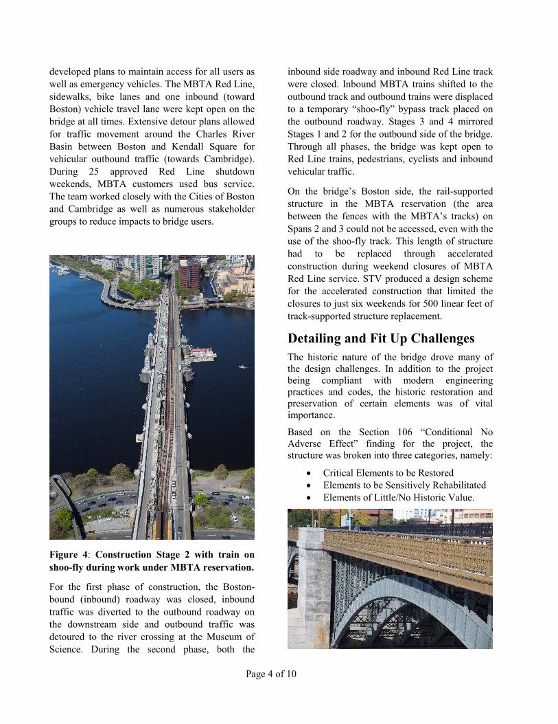
Figure 4: Construction Stage 2 with train on
shoo-fly during work under MBTA reservation.
For the first phase of construction, the Boston-
bound (inbound) roadway was closed, inbound
traffic was diverted to the outbound roadway on
the downstream side and outbound traffic was
detoured to the river crossing at the Museum of
Science. During the second phase, both the
inbound side roadway and inbound Red Line track
were closed. Inbound MBTA trains shifted to the
outbound track and outbound trains were displaced
to a temporary “shoo-fly” bypass track placed on
the outbound roadway. Stages 3 and 4 mirrored
Stages 1 and 2 for the outbound side of the bridge.
Through all phases, the bridge was kept open to
Red Line trains, pedestrians, cyclists and inbound
vehicular traffic.
On the bridge’s Boston side, the rail-supported
structure in the MBTA reservation (the area
between the fences with the MBTA’s tracks) on
Spans 2 and 3 could not be accessed, even with the
use of the shoo-fly track. This length of structure
had to be replaced through accelerated
construction during weekend closures of MBTA
Red Line service. STV produced a design scheme
for the accelerated construction that limited the
closures to just six weekends for 500 linear feet of
track-supported structure replacement.
Detailing and Fit Up Challenges
The historic nature of the bridge drove many of
the design challenges. In addition to the project
being compliant with modern engineering
practices and codes, the historic restoration and
preservation of certain elements was of vital
importance.
Based on the Section 106 “Conditional No
Adverse Effect” finding for the project, the
structure was broken into three categories, namely:
Critical Elements to be Restored
Elements to be Sensitively Rehabilitated
Elements of Little/No Historic Value.

Page 5 of 10
Figure 5: Arch span including historically
critical railing and fascia and sensitively
rehabilitated arch ribs and spandrel columns.
Critical Elements included existing ornamental
cast iron fascia castings and cover plates, and the
existing ornamental pedestrian railing.
Elements to be Sensitively Rehabilitated were
generally the most visible members on the bridge,
including all the arches, the A-line columns along
all spans, and most of the columns and buckle
plates on Spans 1, 2, and 11, which span over
roadways as opposed to the river.
In order to rehabilitate these members with
historic sensitivity, original design detailing was
considered and replicated as necessary, but not
without challenges.
Rivets
The Longfellow Bridge utilized hot riveting during
the original construction, which was a popular
technique used in bridge construction at the time.
Since then, however, rivets have become
essentially obsolete in the construction industry
due to developments within the bolt industry.
Rivets, although cheaper to manufacture, are more
labor intensive and require more specialized skills
and tools than bolts. And bolts have come a long
way throughout history, from becoming
standardized across the world to gaining strength
and consistency between bolts as knowledge and
materials develop.
Around the 1960s and 1970s, bolts took the place
of rivets as the standard fastener type and
construction technique across the bridge industry.
By today, the practice of fabrication of steel
bridges through the use of riveting has essentially
disappeared in the USA.
It proved challenging for the design-build team to
find a steel fabricator with the skilled labor and
tools, or the desire to obtain training and tools, to
work on riveted members for the Longfellow
Bridge rehabilitation. Since the original
construction used rivets, the members designated
to be historically accurate replica members
required riveted construction to match the original
fastener type. These members include all A-line
spandrel columns, sidewalk stringers and sidewalk
beams across all spans. Additionally, any columns
or buckle plates that could not be rehabilitated,
knee braces, and arch rib girder and column
diaphragms on Spans 1, 2 and 11 required
historically accurate replica members fabricated
using rivets.
Members that were designated to have modified
historically accurate replacement members as
opposed to replica members were fabricated using
button-head tension control bolts. These include
the less visible members on Spans 3-10, such as all
column lines except the A-line.
Figure 6: 3-D Model used to show button-head
TC bolts vs hex-head bolts in column
installation.
Due to the dangerous nature of hot riveting, all
riveting was confined to the shop for built-up
members. All field connections between members
were made using bolts. Where possible, button-
head tension control (TC) bolts were used for
connections with the button-head facing towards
the most visible direction of the connection to
maintain a similar aesthetic to the original rivets.
In some instances, such as the inner row of column
connections to the arches, hex-head bolts needed
to be used for installation purposes. Based on the
entering and tightening clearances available with
the column design and the existing rivet holes
being reused for bolts, the torque gun used to
tension the TC bolts did not fit, and hex head bolts
were used instead.
Buckle Plates
Included on the list of historically significant
elements on the bridge to preserve were the buckle
plates. When the bridge was originally constructed
in 1907, steel buckle plates were installed across
the bridge, spanning between stringers and
floorbeams to support the concrete deck and

Page 6 of 10
sidewalk. Two convex “buckles” per panel
provided two-way action to support the
unreinforced concrete slab above. [4]
Figure 7: Existing buckle plates from below
before demolition.
In 1959, during a major rehabilitation of the
bridge, portions of the deck were removed, along
with the supporting buckle plates, and replaced
with sections of reinforced concrete. For the 2018
rehabilitation, the entire deck and sidewalk was
replaced. With a new reinforced concrete, the
buckle plates become obsolete structurally, but
remain important from a historic perspective.
A goal during reconstruction was to salvage and
reuse any of the original buckle plates that were in
good condition, installing the original buckle
plates and any additional replica buckle plates
needed to fill in the three spans over the roadways,
Spans 1, 2 and 11. These spans were so designated
because there is pedestrian access below the spans.
Based on the construction phasing, the Design-
Build team proposed, and the Section 106
Consulting Parties agreed, that it was not feasible
with the schedule to extract, refurbish and reinstall
any of the original buckle plates on the upstream
roadway of Span 11. Replica buckle plates were
fabricated and installed during the early phase
work, with the intent to use all salvaged plates on
Spans 1, 2 and the downstream portion of Span 11.
Upon the continuation of demolition however, all
the existing buckle plates were found to have
advanced deterioration, and none of the original
buckle plates were deemed to be in good condition
or able to be refurbished and reinstalled.
In the end, the roadway decks and sidewalks on
Spans 1, 2 and 11 utilized replica buckle plates as
stay-in-place forms. Spans 3-10 over the river did
not have the same requirements, so instead of
using replica buckle plates as stay-in-place forms,
removable formwork was used to cast both
roadway decks and sidewalks.
Columns
The Longfellow Bridge has over 2,600 spandrel
columns evenly spaced along the arches every 7’-
3” to hold up the deck framing. Each built-up
column consists of two C10 channels, inner web
plates at the top and bottom and lattice bars on all
columns greater than approximately 4 feet tall.
The columns make up an important piece of the
aesthetic of the bridge and are considered
historically important. Many of the columns are
categorized as Elements to be Sensitively
Rehabilitated.
Some of the columns were always intended to be
replaced. Some had considerable deterioration,
especially the D-line columns under the joint
between roadway deck and MBTA reservation.
Others had less deterioration but were in areas that
did not require preservation or sensitive
rehabilitation. These columns were replaced with
new steel.
On Spans 1, 2 and 11, which kept the original
framing plan, all roadway columns were deemed
elements to be preserved. All columns that
required replacement within these spans were
designated to be exact replicas, and consequently
required riveted construction.
On Spans 3-10, all columns other than the A-line
were not held to the same preservation
requirements as Spans 1, 2 and 11. The new
framing on Spans 3-10 was modified slightly from
the original framing, and as such, the new columns
along the D-line on these spans are modified

Page 7 of 10
replica columns, maintaining most of the detailing
from the original columns, but modifying the tops
of the columns to work with the new continuous
floorbeams above. Since these columns are
towards the middle of the bridge and located on
the spans that are less visible from land, modified
replication was allowed instead of historically
accurate replication, and the requirements for
construction method were relaxed on these
columns. Instead of riveted construction, the
interior columns on Spans 3-10 were built up
using button-head tension control bolts.
The columns that received the designation from
the Section 106 Consulting Parties as Elements to
be Sensitively Rehabilitated include the A-line
columns across all spans and all the other roadway
columns on Spans 1, 2 and 11. Aside from any
columns that had severe deterioration, which
needed historically accurate replication, all of
these columns were intended to be refurbished and
reused.
During the first phase of demolition, the A-line
columns were carefully removed and brought off-
site for repair and cleaning. The A-line columns
were generally in good condition with little to no
deterioration and needed only minor repairs. Once
cleaned, the columns were hot-dipped galvanized
and painted. However, within weeks of
galvanizing, it became clear that hot-dipped
galvanizing the steelwork was proving to be
problematic. The columns started bleeding rust at
the rivet locations from in between the plies of
steel at the top and bottom web connection plates.
Figure 8: Riveted steel members on Span 1.
After discussions with the Section 106 Consulting
Parties and the owner about the historic
importance of reusing the original materials
compared to replicating the columns with new
steel to ensure a better service life of the members,
the decision was ultimately made to throw away
all the existing steel and replicate all the columns
using new steel. Each piece of the new column
was hot-dipped galvanized individually before
being used in the built-up member. For the
historically important columns along the A-lines
and on Spans 1, 2 and 11, the columns were
fabricated using riveted construction. The field
connections to the arches below and to the framing
above the columns were made using button-head
TC bolts or hex-head bolts.
Figure 9: Rust bleed on existing column after
hot-dipped galvanization of built-up member.
Steel Fit Up
Aside from the challenges of demonstrating
adequate capacity to allow for the reuse of all of
the arches described previously, a major challenge
of reusing the existing arches, especially through
multiple construction stages, was fit up between
the new and existing steel.
During the rehabilitation of the Longfellow
Bridge, the existing arches remained in place, and
the new columns and deck framing were installed
from the bottom up, attaching new steel piece by
piece to the existing arches. Although the
tolerances of the members of the new framing can
be controlled to great accuracy with modern
fabrication techniques, the tolerance of the field fit
up of those new members to the existing arches
was not as accurate. The supporting arches were
not always at the theoretical design location from
the original construction.
By design, the arches are evenly spaced at 10’-3”
on center beneath the roadways and 5’-0” on
center beneath the MBTA reservation, and the

Page 8 of 10
columns are evenly spaced at 7’-3” on center
along the centerline of the arches.
In reality, the arches are not perfectly straight and
evenly spaced across the spans. Some of the
arches have overall sweeping curves horizontally,
with the entire arch bowing into or away from the
centerline of the bridge. Some arches were slightly
tilted or had slightly skewed webs or top flanges.
As rivets and columns were removed from the
arch flanges, it became clear that the rivet holes at
the column base connection plates did not fully
align with the holes in the existing top arch
flanges. Because rivets are installed in a molten
state, the holes they fit into did not need to fully
align since the molten metal would deform into the
space available. Additionally, the holes did not
always line with the center of the existing rivet
heads.
Figure 10: Gantry used during construction to
place steel roadway framing into best-fit
location based on existing arch misalignments.
All these misalignments, as well as the steel arches
moving up and down with temperature changes,
created a large challenge to obtain accurate and
precise field measurements and to achieve proper
steel fit up during installation.
After interaction with MassDOT, it was agreed
that the primary tool used to build tolerance into
the erection of the steel framework was slotted
holes in slip-critical connections. A connection
could utilize slotted holes as long as at each faying
surface, the slot abutted a standard hole.
The existing rivet holes in the arches were reused
for bolts. Holes were reamed as necessary to be
able to fit a bolt through, and this reamed hole was
considered a slot, even if the dimensions were
outside the standard definitions of slots. This
means that the base plates on top of the arches at
each column location needed standard holes. After
the rivets were removed, field measurements
confirmed the locations of the holes, and new base
plates were drilled to match the field conditions.
Even though the arch ribs were slotted, an
additional slot was used in the same connection at
the column base angles. With the base plates
between the two slotted components, each faying
surface only had one slot. The column base angles
were slotted to give adjustment to the columns in
the longitudinal direction of the bridge. The
columns were installed as close to the theoretical
7’-3” spacing as possible.
Figure 11: 3-D Model used to show slotting in
column base angles for connection to arch rib
to add longitudinal adjustability.
Adjustments in the transverse direction were
achieved at the deck framing level. Slots were
added to floorbeams at each of the column
connections to account for any translation
necessary to correct the misalignments of the
arches and columns below. In a few instances,
floorbeams were lengthened or shortened in
addition to slotting the connections.

Page 9 of 10
Figure 12: The final configuration of the bridge is used by pedestrians, bicycles, automobiles and trains.
Vertical adjustment in the bridge was also a
challenge based on the existing arches. Survey
data was collected on the vertical location of the
arches at the pins and crown as well as numerous
intermediate points along the A-line arches, and a
best-fit parabola was found for each arch. After
adjusting for dead load and temperature effects,
column heights were calculated to place the deck
framing at the proper height for the design profile.
Theoretical modeling of temperature effects on a
large arch structure depends on slightly unrealistic
assumptions, such as the entire arch changing
temperature at the same rate across the entire arch
and each arch being installed as a perfect parabola,
so some imprecision is inherent to modeling. To
account for this, vertical adjustments needed to be
included in the design. Nominal half inch shim
packs were included in the column design height,
and once the columns were installed in the field,
the shims could be removed, or additional shims
could be added to reach the desired height to fit up
the framing. Additional height adjustments were
accounted for with the deck haunches.
A Code Compliant Bridge
The bridge is now AASHTO-compliant [5]
and
Americans with Disabilities Act (ADA)-compliant [6]
. In its final configuration, one outbound travel
lane was eliminated, and bicycle lanes were added
on both the inbound and outbound sides. The
bridge has two inbound travel lanes (the same as
before), one outbound lane, two rebuilt MBTA
Red Line tracks, two bicycle lanes and two
widened sidewalks.
Acknowledgements
The authors would like to thank all participants
involved in the Longfellow Bridge Historic
Rehabilitation, especially the following
organizations.
Owner: Massachusetts Department of
Transportation (MassDOT) and Massachusetts
Bay Transportation Authority (MBTA)
Contractor: J.F. White Contracting Company/
Skanska/Consigli Construction Co. (WSC)
Engineer of Record: STV Incorporated

Page 10 of 10
References
1. MassDOT Accelerated Bridge Program (ABP). Commonwealth of Massachusetts 2018.
https://www.mass.gov/accelerated-bridge-program-abp.
2. Architectural Iron & Steel in the 21st Century: Design and Preservation of Contemporary & Historic
Architecture – Conference, April 4, 2016, MIT, Cambridge, MA. Longfellow Bridge Preservation
Presentation – Presenters: Stacey Donahue, Robert Collari, Wendall Kalsow, Mark Ennis.
3. Commonwealth of Massachusetts Department of Transportation, Technical Provisions, Bridge
Rehabilitation Br. No. B-16-009=C-01-002 (Longfellow Bridge), 2012.
4. City of Boston Printing Department. Report of the Cambridge Bridge Commission and the Report of the
Chief Engineer Upon the Construction of Cambridge Bridge, 1909.
5. American Association of State Highway and Transportation Officials, Standard Specifications for
Highway Bridges, 17th Edition, 2002.
6. Americans with Disabilities Act, Standards for Accessible Design, 2010.